INSTALLATION AND MAINTENANCE MANUAL AUSTART AS50U VANE … · INSTALLATION AND MAINTENANCE MANUAL...
16
INSTALLATION AND MAINTENANCE MANUAL AUSTART AS50U VANE STARTER K.H. EQUIPMENT PTY. LTD. 14-16 WESTPOOL DRIVE, HALLAM VICTORIA 3803 AUSTRALIA PH: +61 3 8786 4766 FX: +61 3 9796 4878 EMAIL: [email protected] WEB: www.khequipment.com.au Issue: 05/10/2012 Rev.01 -1-
Transcript of INSTALLATION AND MAINTENANCE MANUAL AUSTART AS50U VANE … · INSTALLATION AND MAINTENANCE MANUAL...

INSTALLATION AND MAINTENANCE MANUAL
AUSTART AS50U
VANE STARTER
K.H. EQUIPMENT PTY. LTD. 14-16 WESTPOOL DRIVE, HALLAM VICTORIA 3803 AUSTRALIA PH: +61 3 8786 4766 FX: +61 3 9796 4878 EMAIL: [email protected] WEB: www.khequipment.com.au
Issue: 05/10/2012 Rev.01
-1-
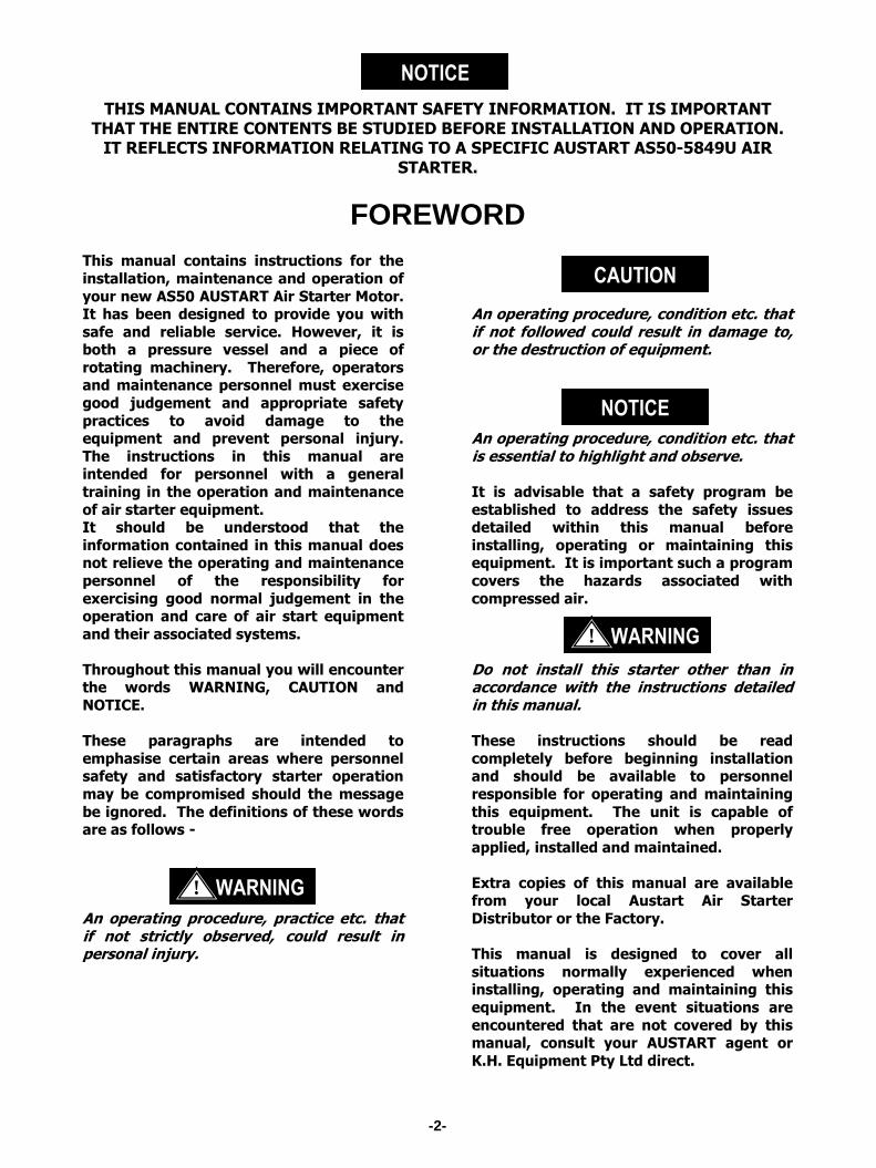
THIS MANUAL CONTAINS IMPORTANT SAFETY INFORMATION. IT IS IMPORTANT THAT THE ENTIRE CONTENTS BE STUDIED BEFORE INSTALLATION AND OPERATION.
IT REFLECTS INFORMATION RELATING TO A SPECIFIC AUSTART AS50-5849U AIR STARTER.
FOREWORD This manual contains instructions for the
installation, maintenance and operation of
your new AS50 AUSTART Air Starter Motor. It has been designed to provide you with
safe and reliable service. However, it is both a pressure vessel and a piece of
rotating machinery. Therefore, operators and maintenance personnel must exercise
good judgement and appropriate safety
practices to avoid damage to the equipment and prevent personal injury.
The instructions in this manual are intended for personnel with a general
training in the operation and maintenance
of air starter equipment. It should be understood that the
information contained in this manual does not relieve the operating and maintenance
personnel of the responsibility for
exercising good normal judgement in the operation and care of air start equipment
and their associated systems.
Throughout this manual you will encounter the words WARNING, CAUTION and
NOTICE.
These paragraphs are intended to
emphasise certain areas where personnel safety and satisfactory starter operation
may be compromised should the message
be ignored. The definitions of these words are as follows -
An operating procedure, practice etc. that if not strictly observed, could result in personal injury.
An operating procedure, condition etc. that if not followed could result in damage to, or the destruction of equipment.
An operating procedure, condition etc. that is essential to highlight and observe.
It is advisable that a safety program be
established to address the safety issues detailed within this manual before
installing, operating or maintaining this equipment. It is important such a program
covers the hazards associated with
compressed air.
Do not install this starter other than in accordance with the instructions detailed in this manual. These instructions should be read
completely before beginning installation and should be available to personnel
responsible for operating and maintaining
this equipment. The unit is capable of trouble free operation when properly
applied, installed and maintained.
Extra copies of this manual are available from your local Austart Air Starter
Distributor or the Factory.
This manual is designed to cover all
situations normally experienced when installing, operating and maintaining this
equipment. In the event situations are
encountered that are not covered by this manual, consult your AUSTART agent or
K.H. Equipment Pty Ltd direct.
NOTICE
WARNING !
NOTICE
CAUTION
WARNING !
-2-

STARTER MODEL FLANGE CODE PINION CODE SPECIAL FEATURES
MODEL PREFIX CODES: AS AUSTART VANE STARTER ATS AUSTART TURBINE STARTER
AS50 AUSTART AIR STARTER 01 SAE 1 09 9TH 3MOD R B BCB (Beryllium Copper Bronze Pinion)
ATS53 AUSTART TURBINE STARTER 02 SAE 2 10 10TH 8/10 R E Threaded Exhaust 1.5”
ATS54 (ATS53 OH) AUSTART TURBINE STARTER 03 SAE 3 11 11TH 6/8 R F Threaded Exhaust 2” Bolt On
AS55 (AS50 OH) AUSTART AIR STARTER 04 SAE 4 12 12TH 8/10 R G Threaded Exhaust 2”
AS61 AUSTART AIR STARTER 13 12TH 8/10 L H Highway Special
ATS63 AUSTART TURBINE STARTER Other options 14 11TH 6/8 L I Inertia Drive
ATS64 (ATS63 OH) AUSTART TURBINE STARTER available 15 10TH 8/10 L J Threaded Exhaust Elbow 2”
AS66 AUSTART AIR STARTER 16 9TH 3MOD L K Kelly Spinner Muffler
AS67 AUSTART AIR STARTER M Mining Spec.(Cast Iron)
AS68 (AS6070) AUSTART AIR STARTER Other options N Short Nose (Inertia ATS77)
AS69 (AS67OH) AUSTART AIR STARTER available P Motor Ports 90°
AS70 AUSTART AIR STARTER R Reduced Muffler
ATS73 AUSTART TURBINE STARTER S Short Muffler
ATS77 AUSTART TURBINE STARTER T Threaded Exhaust 3”
AS75 (AS70 OH) AUSTART AIR STARTER U U Configuration
AS78 (AS7080) AUSTART AIR STARTER V Value Muffler (ATS77)
AS80 AUSTART AIR STARTER X Special – Refer Factory
ATS83 AUSTART TURBINE STARTER
ATS84 (ATS83 OH) AUSTART TURBINE STARTER
AS85 (AS80 OH) AUSTART AIR STARTER
AS90 AUSTART AIR STARTER
ATS93 AUSTART TURBINE STARTER
ATS94 (ATS93 OH) AUSTART TURBINE STARTER
AS95 (AS90 OH) AUSTART AIR STARTER
AS100 AUSTART AIR STARTER
ATS103 AUSTART TURBINE STARTER
ATS183 AUSTART TURBINE STARTER
EXAMPLES OF BASIC STARTER PRODUCT NUMBERING ATS63-0110M PERKINS 1006 SAE1 10TH MINING SPEC ATS63-0409M MWM D916-6 SAE4 9TH MINING SPEC ATS73-0311 CUMMINS N14 SAE3 11TH ATS73-0314 CUMMINS N14 SAE3 11TH LH ATS73-0311I DETROIT 12V71 SAE3 11TH INERTIA DRIVE ATS73-0314I DETROIT 12V71 SAE3 11TH INERTIA DRIVE LH ATS73-0312M CATERPILLAR 3306 SAE3 12TH MINING SPEC ATS83-0311IT WAUKESHA 7072 SAE3 11TH INERTIA THREADED EXHAUST
AUSTART PRODUCT NUMBERING
-3-

INSTALLATION AND PREPARATION FOR OPERATION
Ensure air supply is isolated before installation, removal, maintenance or
adjustment of your AUSTART starter.
Before any starter is taken out of service first
bleed the Air Receiver of air and any moisture that may have accumulated by
opening up the drain valve. Do not bleed by removing Receiver plugs.
Remove air hoses to ensure complete safety
once the air supply has been isolated and the Receiver has been bled.
The Air Receiver must be manufactured to an
applicable pressure vessel code such as AS 1210, or similar.
Only use air hoses and fittings that are of
adequate size as indicated in the installation schematic (page 6)
Always carry out a pressure test on the
complete starting system according to Clause 7 on Page 5 before beginning operation. Do
not begin operations until satisfied the unit has been installed correctly.
Always use recommended lubricants where
prescribed by this manual. Under no circumstances use flammable or volatile
liquids.
Ensure all fasteners are torqued to the values
prescribed in this manual. Use thread
sealant where indicated.
To ensure warranty provisions are not
invalidated use only genuine AUSTART
replacement parts. Non-genuine parts may cause service and performance problems and
may affect the safe operation of your starter.
WARNING !
-4-

INSTALLING THE STARTER AND PIPEWORK
Refer to the Starter Installation Schematic drawing on page 6 1. The air supply line should ideally exit
from the top or side of the Air Receiver.
Do not connect Air Supply Line to the
bottom of the Air Receiver. Moisture and system contaminants collect at the receiver bottom and can damage the Austart Starter internals if allowed to pass through. Periodically drain moisture from the Air Receiver using a drain valve connected at the Receiver bottom.
2. Install a LS1000M lube relay valve. The Austart AS50 series air starter should be
lubricated with light weight oil or diesel
fuel.
3. Mount the Starter Control Button SC25
onto the vehicle dash-board or appropriate control panel and connect
to the Air Receiver using a minimum of ¼” (6mm) line.
Ensure the inlet side of the Starter Control Button connects to the line from the Receiver. Any Safety “Switches” should be installed in this line between the Starter Control Button and the Air Receiver.
4. Determine the practicality of running
the main air supply hose or pipe from
the exit of the Relay Valve to the inlet of the Austart Starter after the Austart
Starter is mounted. It may be easier to fit the hose before the Austart Starter is
mounted in position.
5. Once the Austart Starter is mounted, fit the remaining ¼” (6mm) control lines
from the Austart Starter to the Starter Control Button and Relay Valve
respectively (Refer page 6).
6. Make all hose or pipe connections leak
proof using a suitable thread sealant.
7. Once the connections have been made pressurise the system and check for
leaks using “soapy” water or similar solution.
CAUTION
NOTICE
-5-

-6-

-7-

-8-

- XXX DENOTES OPTIONS AVAILABLE
-9-
PA
RT
S B
RE
AK
DO
WN
AUSTART AS50U PARTS BREAKDOWN
ITEM PART NO.
EXT. DESCRIPTION
QTY ITEM PART NO.
EXT. DESCRIPTION QTY
1 6001 -000 SCREW 4 31 6016 -XXX DRIVE ASSEMBLY 1 2 5002 -100 END CAP 1 32 5018 -XXX NOSE HOUSING 1 3 5301 -000 SPECIAL NUT 1 33 5001 -000 BEARING + 1 4 5026 -000 BEARING + 1
5 5006 -000 SCREW 6 6 5004 -100 END COVER 1 5040 -920 SERVICE KIT CONSISTS AS MARKED + A.R.
7 5008 -900 BLADE SET + 1 8 5009 -100 ROTOR 1 9 5007 -910 MOTOR HOUSING ASSY 1 10 5010 -100 END COVER 1 11 6310 -000 BEARING + 1 12 6308 -000 CIRCLIP + 1 13 5111 -200 GEAR COVER 1 14 5021 -000 SCREW 6 15 6767 -100 IDLER PIN 1 16 6115 -000 SCREW 4 17 6612 -000 CIRCLIP + 2 18 5113 -100 IDLER GEAR 1 19 6611 -000 BEARING + 1 20 6771 -100 SPACER 1
21 5112 -100 COVER PLATE 1
22 6005 -000 SCREW 5 23 6617 -000 CIRCLIP + 1 24 5017 -100 DRIVE GEAR 1 25 6619 -000 CIRCLIP - FITTED + 1
26 6012 -000 BEARING + 1
27 6621 -000 SEAL + 1
28 6729 -000 SCREW 4 29 5019 -110 DRIVE SHAFT 1 30 6624 -100 WOODRUFF KEY (MODIFIED) 1

-10-

MAINTENANCE
DISASSEMBLY Refer to the Exploded View drawing on page 8
Begin by separating the motor sub assy (9)
from the gear cover assy (13).
1. Remove screws (22) and cover plate
(21).
2. Remove spacer (20), idler gear (18) and
the six screws (14).
3. Remove motor sub assy (9) from gear cover (13).
The Sub-Assemblies may now be dismantled separately. Disassembly of any
of these two Sub-Assemblies is detailed in
the exploded view on page 8 and is basically in the order shown. Refer also to
the following instructions:
Gear Cover Assembly
1. Remove screws (28) and remove nose
(32) from gear cover (13). Loosen drive retaining screw from drive and remove
drive assy (31) from drive shaft (29).
2. Invert and support gear cover (13) with
drive shaft in the downward position.
3. Remove circlip (23) with circlip pliers and gently press out drive shaft (29)
from gear (24) and bearing (26).
4. Remove circlip (25) using circlip pliers.
Place gear cover (13) on bench. Using a
pressing tool, press out bearing (26) and seal (27).
5. Remove nose bearing (33) from nose (32).
Motor Assembly
1. Remove the four screws (1) and cap (2).
2. Invert motor assy and hold shaft of rotor
(8) in a vice using soft jaws.
3. Remove nut (3) and place motor assy on bench.
4. Support motor housing (9) and lightly tap threaded end of rotor (8) which will remove end cover (10) and rotor (8) as an assembly.
5. Support end cover (10) and press rotor (8) out through bearing (11).
6. Remove circlip (12) using circlip pliers and press out bearing (11).
7. Remove six screws (5) support motor housing (9) using a soft drift, tap end cover (6) away from motor housing (9).
8. Support end cover (6) and press out bearing (4).
WARNING !
-11-

INSPECTION Refer to the Exploded View drawing on page 8
1. Visually inspect all parts removed during
disassembly for excessive wear or
damage. Replace any damaged or questionable parts.
2. Pay particular attention to the slots in rotor (8) for excessive wear, also the
condition of motor housing liner for
excessive wear and scoring. If excessive scoring has occurred or the liner has
irregular wear patterns honing of the motor housing liner is required.
Serviceable limits as follows:
2.125 – 2.130 inch
53.98 – 54.102 metric
3. Also pay particular attention to all gear
teeth looking for cracked or broken
teeth and excessive wear. Check the pinion on the Drive Assembly (31) for
evidence of unusual contact patterns resulting from misalignment or
improper engagement. Remove any
burrs or replace if questionable.
4. Check all bearings are free to rotate and
do not have excessive play between races. If in doubt replace questionable
bearings.
Do not wash shielded bearings that are to be reused in solvent or blow with compressed air as it may remove internal lubrication. Bearings that are to be reused should be cleaned by wiping the end shields with a clean cloth.
5. Clean all other parts that are going to be
reused with commercially approved solvents.
Ensure cleaning operations are carried out in a properly vented area away from open flames.
6. It is recommended that when servicing
your Austart Air Starter always replace complete repair kit contents.
WARNING !
CAUTION
-12-
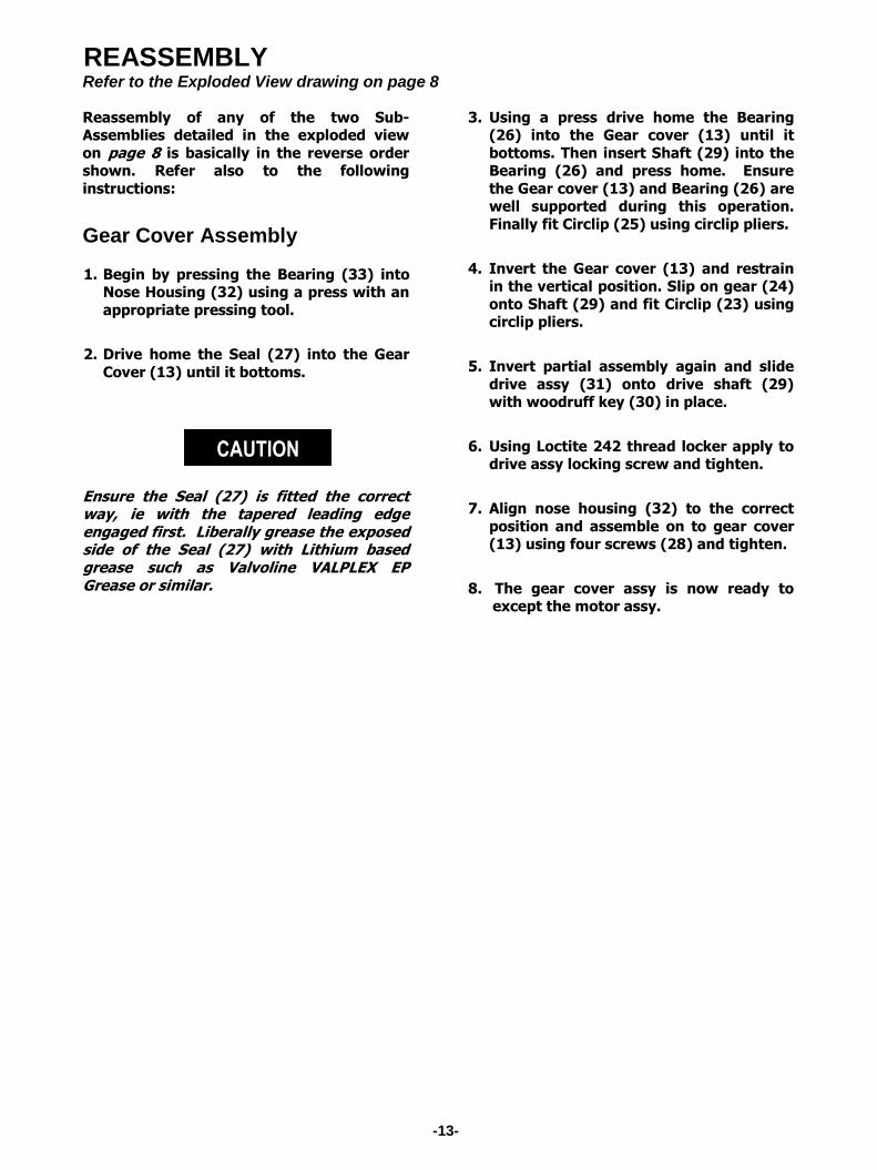
REASSEMBLY Refer to the Exploded View drawing on page 8
Reassembly of any of the two Sub-Assemblies detailed in the exploded view
on page 8 is basically in the reverse order shown. Refer also to the following
instructions:
Gear Cover Assembly
1. Begin by pressing the Bearing (33) into Nose Housing (32) using a press with an
appropriate pressing tool.
2. Drive home the Seal (27) into the Gear
Cover (13) until it bottoms.
Ensure the Seal (27) is fitted the correct way, ie with the tapered leading edge engaged first. Liberally grease the exposed side of the Seal (27) with Lithium based grease such as Valvoline VALPLEX EP Grease or similar.
3. Using a press drive home the Bearing (26) into the Gear cover (13) until it
bottoms. Then insert Shaft (29) into the Bearing (26) and press home. Ensure
the Gear cover (13) and Bearing (26) are well supported during this operation.
Finally fit Circlip (25) using circlip pliers.
4. Invert the Gear cover (13) and restrain in the vertical position. Slip on gear (24)
onto Shaft (29) and fit Circlip (23) using circlip pliers.
5. Invert partial assembly again and slide
drive assy (31) onto drive shaft (29) with woodruff key (30) in place.
6. Using Loctite 242 thread locker apply to drive assy locking screw and tighten.
7. Align nose housing (32) to the correct
position and assemble on to gear cover (13) using four screws (28) and tighten.
8. The gear cover assy is now ready to except the motor assy.
CAUTION
-13-

Motor Assembly
1. Install bearing (4) into end cover (6) and
bearing (11) into end cover (10).
2. Confirming direction of air starter. For counter clock-wise air starters refer
diagram below. Start by placing motor housing (9) on a bench with the three
intake directional slots facing to the left.
3. Apply a thin layer of liquid gasket such
as Loctite 515 or similar to mating face of motor housing.
4. Knock on end cover (6) with a soft
hammer and insert the six screws (5).
5. Invert the motor housing (9) and
support bearing (4) and end cover (6).
6. Press rotor (8) into bearing (4) insert
blades (7) into rotor (8) slots making
sure blades are pushed out towards motor housing liner. Apply thin layer of
liquid gasket such as Loctite 515 or similar to mating face of motor housing.
7. Insert end cover (10) and bearing (11) over rotor shaft with an appropriate
tool. Press home end cover (10) and
bearing (11).
8. Fit circlip (12) using circlip pliers.
9. Invert motor assy and hold gear teeth of rotor (8) in vice using soft jaws.
10. Apply oil to thread of rotor (8) and
install nut (3) tighten nut to a torque of 20-25 ft lb (27-34Nm)
11. Apply a thin layer of liquid gasket to cap (2) and mount onto end cover (6) with
the four screws (1).
12. Carefully align motor assembly to the
correct position and install into gear cover assy (13), install screws (14) and
tighten.
13. Install 1st circlip (17) into idler gear (18) using circlip pliers, carefully press
bearing (19) and install 2nd circlip (17).
14. Invert gear cover assembly, align gears
and assemble idler gear (18) and spacer
(20) onto idler pin (15).
15. Liberally pack gear teeth with suitable
grease such as Valvoline Valplex EP grease or similar.
16. Apply a thin layer of liquid gasket such as Loctite 515 to cover plate face of gear
cover (13). Install cover plate (21) and
screws (22).
17. Apply lubricating oil into inlet port of
motor housing (9). Attach air line and test operation of air motor.
18. The Austart air starter is now assembled
and ready for installation. Refer to installation and operation section of this
manual.
-14-
WARRANTY POLICY All Austart Products supplied by K.H. Equipment Pty. Ltd. (herein called “the
Manufacturer”) is warranted to be free from any defect in workmanship and material
under conditions of normal use and service for engine starting applications for a
period of 12 months from the date of purchase by the first user. Normal wear and
tear is excluded from the warranty cover.
The Manufacturer will replace or repair at their works, without cost, any Austart
Starter or parts found to be defective or at their discretion choose to refund the
purchase price less a reasonable allowance for depreciation in exchange for the
starter or part should the item prove impossible to repair or replace.
This warranty shall not apply to any Austart Starter or parts which have been altered
or repaired or purchased outside the Manufacturer and its assigned agents nor to
equipment or parts that have been subject to misuse including overloading, neglect,
accident or damage, nor to any part or parts improperly applied or installed.
This warranty is in lieu of all other warranties and conditions statutory or otherwise
expressed or implied and of all other obligations or liabilities on the Manufacturer’s
part. The Manufacturer’s maximum liability is limited to the purchase price of the
starter and is not liable for any consequential damage, loss or expense.
Repeat engine starting attempts must be delayed for 15 seconds to allow all Austart
Starter and engine components to stop rotating to avoid damage or adverse wear of
components.
-15-

-16-
NOTES ________________________________________________________________________
________________________________________________________________________
________________________________________________________________________
________________________________________________________________________
________________________________________________________________________
________________________________________________________________________
________________________________________________________________________
________________________________________________________________________
________________________________________________________________________
________________________________________________________________________
________________________________________________________________________
________________________________________________________________________
________________________________________________________________________
________________________________________________________________________
________________________________________________________________________
________________________________________________________________________
________________________________________________________________________
________________________________________________________________________
________________________________________________________________________
________________________________________________________________________
________________________________________________________________________
________________________________________________________________________
________________________________________________________________________
________________________________________________________________________
________________________________________________________________________
________________________________________________________________________
________________________________________________________________________
DISTRIBUTED BY


![Digital HD Video Camera Recorder HDR-AS50 · 2016-03-03 · Digital HD Video Camera Recorder HDR-AS50 Read This First Identifying the parts [1] Screen display [2] ... Time-lapse capture](https://static.fdocuments.us/doc/165x107/5f64e20a7b5c3d0e6c633df8/digital-hd-video-camera-recorder-hdr-as50-2016-03-03-digital-hd-video-camera-recorder.jpg)