
©2008 Armstrong International, Inc. Basic Steam Trap Operation.
Installation and Maintenance
IB-87-D
PLEASE READ AND SAVE THESE INSTRUCTIONS
The Armstrong Series CS-10 steam-to-steam humidifiers use existing steam toproduce new, pure steam at atmospheric pressure via a heat exchanger. The vaporis discharged into a duct of an air-handling system.
To allow Series CS steam-to-steam humidifiers to function to their full capability, becertain to install in accordance with the following Armstrong recommendations.
Series CS Steam-to-Steam Humidifiers
Series CS Steam-to-Steam Humidifiers
2
Table of Contents
Pre-Installation ............................................................................................................... 3• Check Shipment .............................................................................................. 3• Check Local Codes ......................................................................................... 3• Site Selection .................................................................................................. 3
Installation• Mounting The Humidifier .................................................................................. 4• Installation
• CS-10-SF .................................................................................................. 4-6• CS-10 - C or S ........................................................................................... 6-8• CS-10 - CB or SB .................................................................................... 8-11
• Duct Safety Devices....................................................................................... 12• Steam Dispersion Tubes ........................................................................... 12-13• Physical Data
• CS-11/12/13 .......................................................................................... 14-15• CS-14 ......................................................................................................... 15• CS-15 ......................................................................................................... 16
• Tank Lid Options• CS-14 ......................................................................................................... 16• CS-15 ......................................................................................................... 16
Principles of Operation, Steam to Steam Humidifiers .............................................. 17
Start-up Procedure for Series CS-10-SF Humidifiers ............................................... 17
Start-up Procedure for Series CS-10-C or S Humidifiers ......................................... 18
Start-up Procedure for Series CS-10-CB or SB ........................................................ 19
Maintenance Schedule ............................................................................................... 19One Week After Start-Up ..................................................................................... 19General Maintenance........................................................................................... 20One Month After Start-Up ..................................................................................... 20Procedure For Cleaning ...................................................................................... 20
Troubleshooting Guide ............................................................................................... 22
Diagnostics (Series CS-10-CB or SB only) ............................................................... 24
Clearing “Error” Codes............................................................................................... 25
PC Board Dip Switch Settings ................................................................................... 26
Series CS Steam-to-Steam Humidifiers
3
Pre-Installation
1) Check ShipmentA claim should be filed with the transportation company (and reported to Armstrong)if any items are missing or damaged.
Two complete sets of installation instructions have been shipped with your unit. Oneis for the installer’s use, the second is for the owner’s files.
2) Check Local CodesSeries CS-10 Humidifiers should be installed in accordance with ALL applicablebuilding, plumbing, and electrical codes.
3) Site Selection
Do not place the CS-10 Steam-to-Steam humidifiers above false ceilings or inlocations where unusual instances or malfunctions of the humidifier or thesystem might cause damage to non-repairable, unreplaceable,or pricelessproperty.
CS-10 humidifiers should be installed in locations that allow routine inspectionand accessibility for maintenance operations. The control box for the seriesCS should be mounted in a location where it can be serviced.
The mounting surface should be a wall capable of supporting the maximumhumidifier operating weight or a (recommended) suitable floor space. The unit maybe suspended from a duct, but accessibility for maintenance purposes is necessary.The location chosen should be indoors with a minimum ambient temperature of40°F (4°C) and a maximum of 130°F (54°C).
The location should be close enough to the air duct so that the length of steam hoseor pipe is as short as feasible. A length of 10 feet (3.4 m) or less is ideal; the maximumrecommended length for running copper tube is 40 feet (12 m) equivalent pipingdistance.
Model Number CS-11 CS-12 CS-13 CS-14 CS-15Approximate Shipping Weight 85 lb / 39 kg 145 lb / 66 kg 160 lb / 73 kg 400 lb / 181 kg 520 lb / 235 kgMaximum Operating Weight* 183 lb / 83 kg 398 lb / 180 kg 413 lb / 187 kg 920 lb / 417 kg 1840 lb / 834 kg*Less steam trap, strainer, control valve, dispersion tube(s) and fittings.
Table 3-1. Weights
Series CS Steam-to-Steam Humidifiers
4
The unit should have ready access to a supply of water, electrical service for theoptional drain valve or the control panel, and a sewer into which the drain valve andoverflow connections can discharge hot (212°F/100°C) water. In addition, steamsupply, condensate return, and control air supply (if used) must be accessible to theunit.
NOTE: Ordinary tap water can be used. However, reduced maintenance andcleaning will be required if softened, demineralized, or deionized water is used.For demineralized and deionized water applications, the unit must have a specialcoating on the heat exchanger to resist corrosion from the ultra-pure water—CONTACT FACTORY. Do not use brackish or contaminated water.
Installation
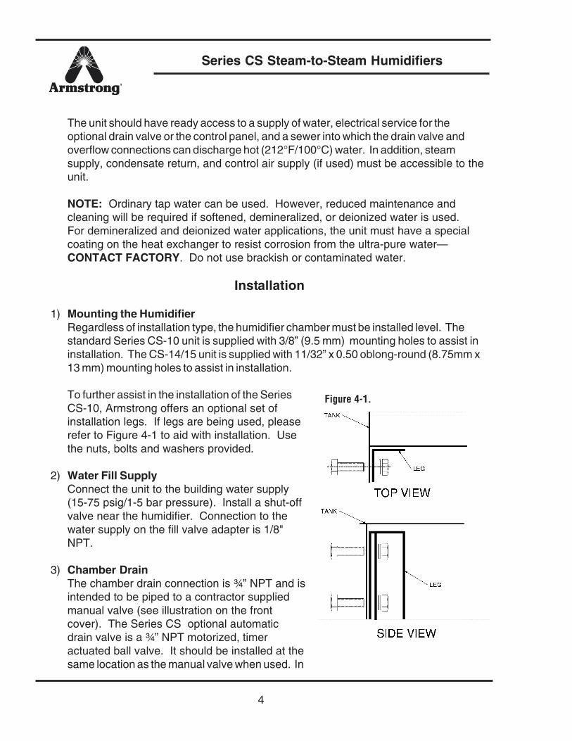
1) Mounting the HumidifierRegardless of installation type, the humidifier chamber must be installed level. Thestandard Series CS-10 unit is supplied with 3/8” (9.5 mm) mounting holes to assist ininstallation. The CS-14/15 unit is supplied with 11/32” x 0.50 oblong-round (8.75mm x13 mm) mounting holes to assist in installation.
To further assist in the installation of the SeriesCS-10, Armstrong offers an optional set ofinstallation legs. If legs are being used, pleaserefer to Figure 4-1 to aid with installation. Usethe nuts, bolts and washers provided.
2) Water Fill SupplyConnect the unit to the building water supply(15-75 psig/1-5 bar pressure). Install a shut-offvalve near the humidifier. Connection to thewater supply on the fill valve adapter is 1/8"NPT.
3) Chamber DrainThe chamber drain connection is ¾” NPT and isintended to be piped to a contractor suppliedmanual valve (see illustration on the frontcover). The Series CS optional automaticdrain valve is a ¾” NPT motorized, timeractuated ball valve. It should be installed at thesame location as the manual valve when used. In
Figure 4-1.
Series CS Steam-to-Steam Humidifiers
5
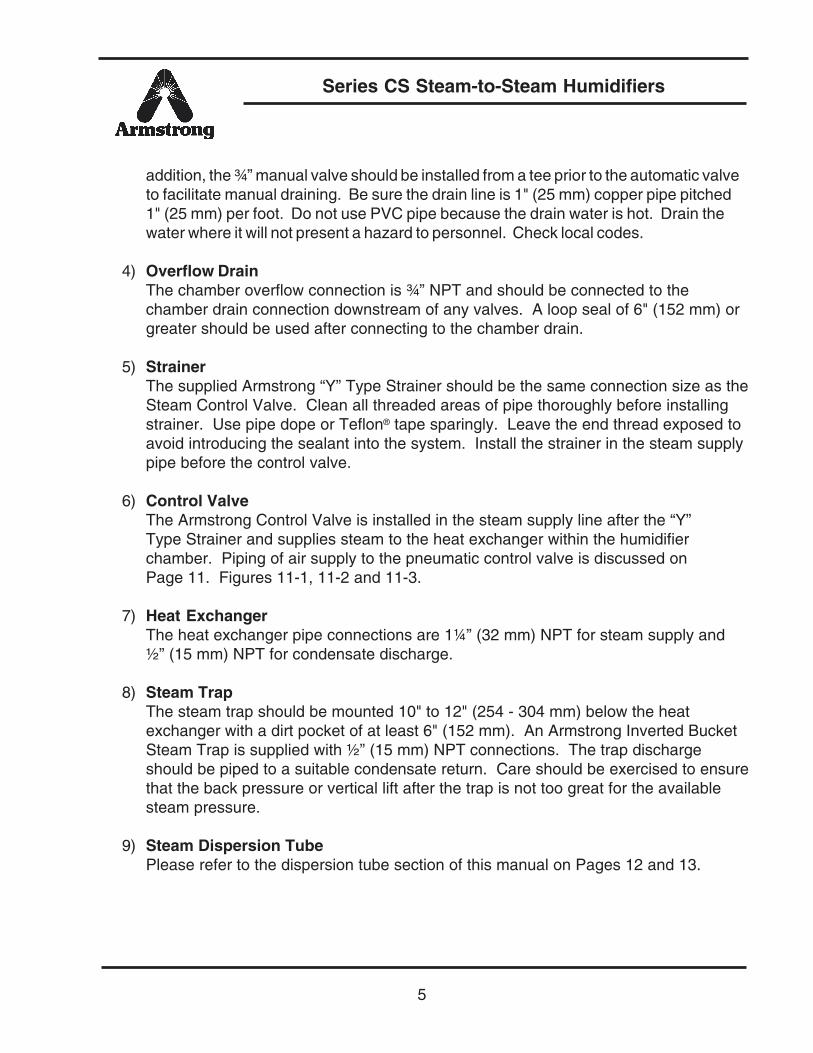
addition, the ¾” manual valve should be installed from a tee prior to the automatic valveto facilitate manual draining. Be sure the drain line is 1" (25 mm) copper pipe pitched1" (25 mm) per foot. Do not use PVC pipe because the drain water is hot. Drain thewater where it will not present a hazard to personnel. Check local codes.
4) Overflow DrainThe chamber overflow connection is ¾” NPT and should be connected to thechamber drain connection downstream of any valves. A loop seal of 6" (152 mm) orgreater should be used after connecting to the chamber drain.
5) StrainerThe supplied Armstrong “Y” Type Strainer should be the same connection size as theSteam Control Valve. Clean all threaded areas of pipe thoroughly before installingstrainer. Use pipe dope or Teflon® tape sparingly. Leave the end thread exposed toavoid introducing the sealant into the system. Install the strainer in the steam supplypipe before the control valve.
6) Control ValveThe Armstrong Control Valve is installed in the steam supply line after the “Y”Type Strainer and supplies steam to the heat exchanger within the humidifierchamber. Piping of air supply to the pneumatic control valve is discussed onPage 11. Figures 11-1, 11-2 and 11-3.
7) Heat ExchangerThe heat exchanger pipe connections are 1¼” (32 mm) NPT for steam supply and½” (15 mm) NPT for condensate discharge.
8) Steam TrapThe steam trap should be mounted 10" to 12" (254 - 304 mm) below the heatexchanger with a dirt pocket of at least 6" (152 mm). An Armstrong Inverted BucketSteam Trap is supplied with ½” (15 mm) NPT connections. The trap dischargeshould be piped to a suitable condensate return. Care should be exercised to ensurethat the back pressure or vertical lift after the trap is not too great for the availablesteam pressure.
9) Steam Dispersion TubePlease refer to the dispersion tube section of this manual on Pages 12 and 13.
Series CS Steam-to-Steam Humidifiers
6
Installation of the CS-10-C or S Models
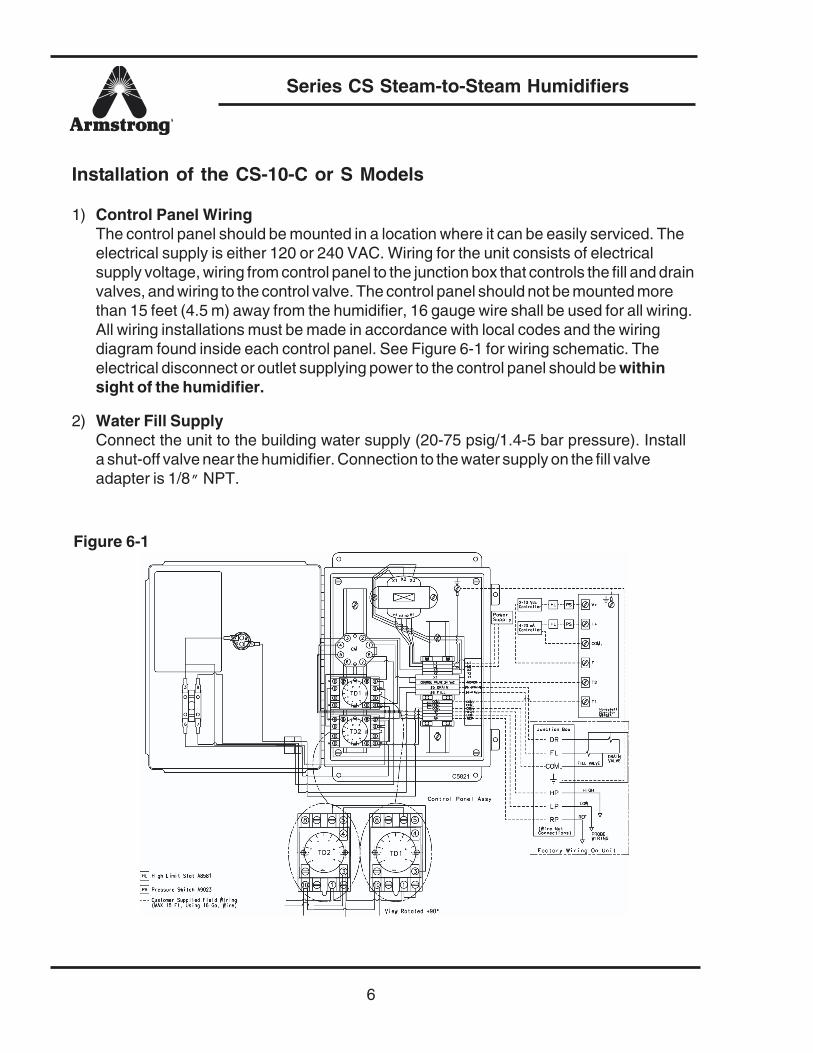
1) Control Panel WiringThe control panel should be mounted in a location where it can be easily serviced. Theelectrical supply is either 120 or 240 VAC. Wiring for the unit consists of electricalsupply voltage, wiring from control panel to the junction box that controls the fill and drainvalves, and wiring to the control valve. The control panel should not be mounted morethan 15 feet (4.5 m) away from the humidifier, 16 gauge wire shall be used for all wiring.All wiring installations must be made in accordance with local codes and the wiringdiagram found inside each control panel. See Figure 6-1 for wiring schematic. Theelectrical disconnect or outlet supplying power to the control panel should be withinsight of the humidifier.
2) Water Fill SupplyConnect the unit to the building water supply (20-75 psig/1.4-5 bar pressure). Installa shut-off valve near the humidifier. Connection to the water supply on the fill valveadapter is 1/8” NPT.
Figure 6-1
Series CS Steam-to-Steam Humidifiers
7
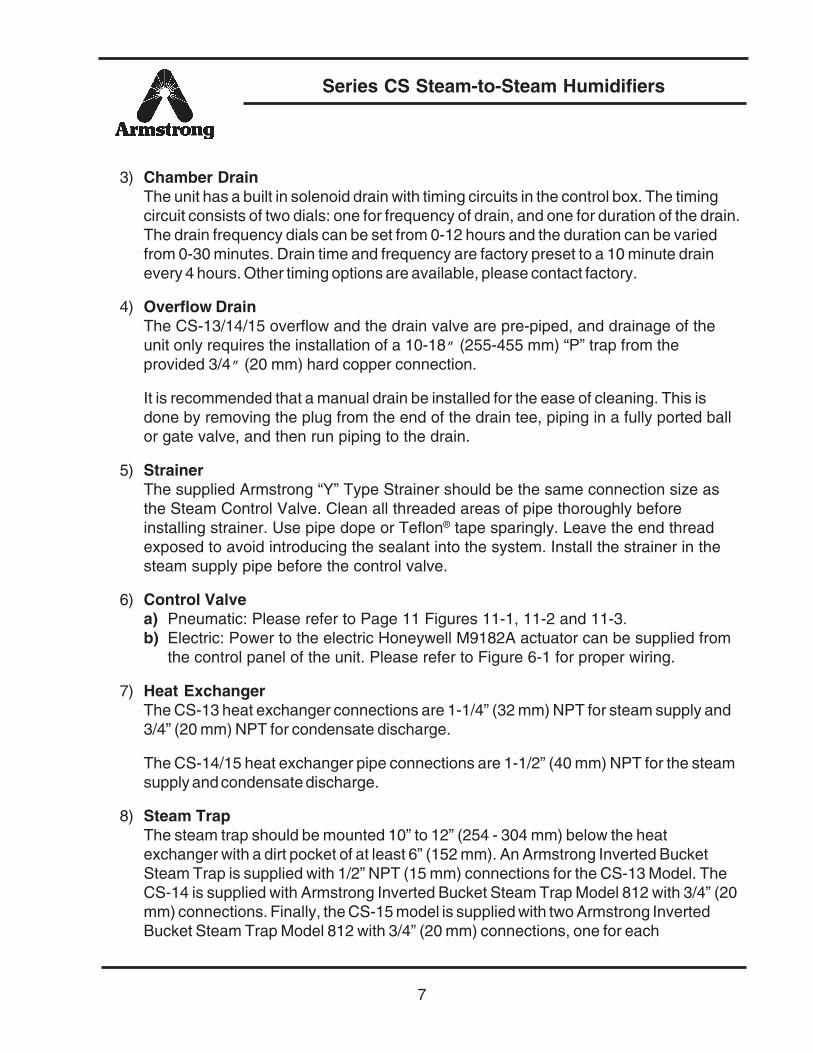
3) Chamber DrainThe unit has a built in solenoid drain with timing circuits in the control box. The timingcircuit consists of two dials: one for frequency of drain, and one for duration of the drain.The drain frequency dials can be set from 0-12 hours and the duration can be variedfrom 0-30 minutes. Drain time and frequency are factory preset to a 10 minute drainevery 4 hours. Other timing options are available, please contact factory.
4) Overflow DrainThe CS-13/14/15 overflow and the drain valve are pre-piped, and drainage of theunit only requires the installation of a 10-18” (255-455 mm) “P” trap from theprovided 3/4” (20 mm) hard copper connection.
It is recommended that a manual drain be installed for the ease of cleaning. This isdone by removing the plug from the end of the drain tee, piping in a fully ported ballor gate valve, and then run piping to the drain.
5) StrainerThe supplied Armstrong “Y” Type Strainer should be the same connection size asthe Steam Control Valve. Clean all threaded areas of pipe thoroughly beforeinstalling strainer. Use pipe dope or Teflon® tape sparingly. Leave the end threadexposed to avoid introducing the sealant into the system. Install the strainer in thesteam supply pipe before the control valve.
6) Control Valvea) Pneumatic: Please refer to Page 11 Figures 11-1, 11-2 and 11-3.b) Electric: Power to the electric Honeywell M9182A actuator can be supplied from
the control panel of the unit. Please refer to Figure 6-1 for proper wiring.
7) Heat ExchangerThe CS-13 heat exchanger connections are 1-1/4” (32 mm) NPT for steam supply and3/4” (20 mm) NPT for condensate discharge.
The CS-14/15 heat exchanger pipe connections are 1-1/2” (40 mm) NPT for the steamsupply and condensate discharge.
8) Steam TrapThe steam trap should be mounted 10” to 12” (254 - 304 mm) below the heatexchanger with a dirt pocket of at least 6” (152 mm). An Armstrong Inverted BucketSteam Trap is supplied with 1/2” NPT (15 mm) connections for the CS-13 Model. TheCS-14 is supplied with Armstrong Inverted Bucket Steam Trap Model 812 with 3/4” (20mm) connections. Finally, the CS-15 model is supplied with two Armstrong InvertedBucket Steam Trap Model 812 with 3/4” (20 mm) connections, one for each

Series CS Steam-to-Steam Humidifiers
8
condensate connection of the heat exchanger. The trap discharge should be piped to asuitable condensate return. Care should be exercised to ensure that the back pressureor vertical lift after the trap is eliminated.
9) Steam Dispersion TubePlease refer to the dispersion tube selection section of this manual (Pages 12and 13).
Installation of the CS-10-CB, or SB Models
1) Control Panel WiringThe control panel should be mounted in a location where it can be easily serviced.The electrical supply to the control panel is 120 VAC (240 VAC option available).Wiring for the unit consists of electrical supply wiring from control panel to thejunction box on the tank assembly and wiring to the control valve. The control panelshould not be mounted more than 15 feet (4.5 m) away from the humidifier, 16gauge wire shall be used for all wiring. All wiring installations must be made inaccordance with local codes and the wiring diagram found inside each control panel.See Figure 8-1 for schematic. The electrical disconnect or outlet supplying power to thecontrol panel should be within sight of the humidifier.
Figure 8-1.
Wiring SchematicCS-10-CB or SB
Series CS Steam-to-Steam Humidifiers
9
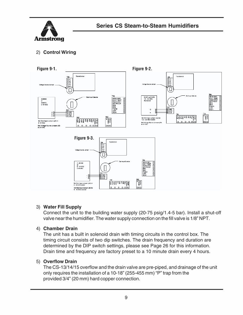
2) Control Wiring
3) Water Fill SupplyConnect the unit to the building water supply (20-75 psig/1.4-5 bar). Install a shut-offvalve near the humidifier. The water supply connection on the fill valve is 1/8” NPT.
4) Chamber DrainThe unit has a built in solenoid drain with timing circuits in the control box. Thetiming circuit consists of two dip switches. The drain frequency and duration aredetermined by the DIP switch settings, please see Page 26 for this information.Drain time and frequency are factory preset to a 10 minute drain every 4 hours.
5) Overflow DrainThe CS-13/14/15 overflow and the drain valve are pre-piped, and drainage of the unitonly requires the installation of a 10-18” (255-455 mm) “P” trap from theprovided 3/4” (20 mm) hard copper connection.
Figure 9-1.
Figure 9-3.
Figure 9-2.
Series CS Steam-to-Steam Humidifiers
10
It is recommended that a manual drain be installed for the ease of cleaning. This isdone by removing the plug from the end of the drain tee, piping in a fully ported ball orgate valve, and then run piping to the drain.
6) StrainerThe supplied Armstrong “Y” Type Strainer should be the same connection size as theSteam Control Valve. Clean all threaded areas of pipe thoroughly before installingstrainer. Use pipe dope or Teflon® tape sparingly. Leave the end thread exposed toavoid introducing the sealant into the system. Install the strainer in the steam supplypipe before the control valve.
7) Control Valvea) Pneumatic: If a pneumatic valve is to be used, the control panel will have a
4 – 11 psi transducer installed. The output of this transducer is controlled by the PCBoard, and will be used to control the pneumatic actuator. An electronic signal mustbe provided to control panel even if pneumatic control valve is to be used.
b) Electric: Power to the electric Honeywell M9182A actuator can be supplied fromthe control panel of the unit. Refer to Figure 8-1 for proper wiring. Otheractuators may be used. Please consult factory
8) Heat ExchangerThe CS-11/12/13 heat exchanger connections are 1 1/4” (32 mm) NPT for steamsupply and 3/4” (20 mm) NPT for condensate discharge.
The CS-14/15 heat exchanger pipe connections are 1 1/2” (40 mm) NPT for the steamsupply and condensate discharge.
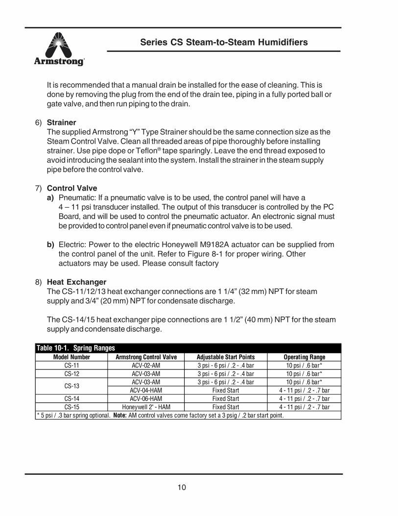
Model Number Armstrong Control Valve Adjustable Start Points Operating RangeCS-11 ACV-02-AM 3 psi - 6 psi / .2 - .4 bar 10 psi / .6 bar*CS-12 ACV-03-AM 3 psi - 6 psi / .2 - .4 bar 10 psi / .6 bar*
ACV-03-AM 3 psi - 6 psi / .2 - .4 bar 10 psi / .6 bar*ACV-04-HAM Fixed Start 4 - 11 psi / .2 - .7 bar
CS-14 ACV-06-HAM Fixed Start 4 - 11 psi / .2 - .7 barCS-15 Honeywell 2" - HAM Fixed Start 4 - 11 psi / .2 - .7 bar
Table 10-1. Spring Ranges
CS-13
* 5 psi / .3 bar spring optional. Note: AM control valves come factory set a 3 psig / .2 bar start point.
Series CS Steam-to-Steam Humidifiers
11
9) Steam TrapThe steam trap should be mounted 10” to 12” (254 - 304 mm) below the heatexchanger with a dirt pocket of at least 6” (152 mm). An Armstrong Inverted BucketSteam Trap is supplied with 1/2” (15 mm) NPT connections for Models CS-11/12/13.The CS-14 is supplied with Armstrong inverted bucket steam trap Model 812 with 3/4” (20 mm) connections. Finally, the CS-15 model is supplied with two Armstronginverted bucket steam trap Model 812 with 3/4” (20 mm) connections, one for eachcondensate connection of the heat exchanger. The trap discharge should be piped toa suitable condensate return. Care should be exercised to ensure that the backpressure or vertical lift after the trap is eliminated.
10) Steam Dispersion TubePlease refer to the dipsersion tube section of this manual (Pages 12 and 13).
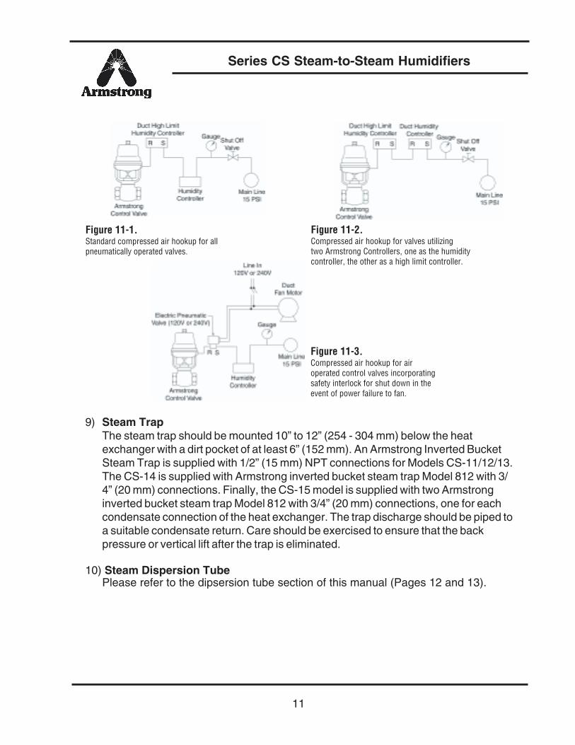
Figure 11-1.Standard compressed air hookup for allpneumatically operated valves.
Figure 11-2.Compressed air hookup for valves utilizingtwo Armstrong Controllers, one as the humiditycontroller, the other as a high limit controller.
Figure 11-3.Compressed air hookup for airoperated control valves incorporatingsafety interlock for shut down in theevent of power failure to fan.
Series CS Steam-to-Steam Humidifiers
12
Duct Safety Devices
High Limit HumidistatA Duct mounted high limit humidistat is recommended to prevent over-saturation ofthe duct air. Use an on-off controller that opens on fault (high humidity). Humidistatshould be set for a maximum of 90% RH. Alternately, a modulation high limithumidistat may be used on applications such as variable air volume (VAV). Locatedthe high limit humidistat approximately 10’ (3 m) downstream of the dispersionmanifold. If 10’ (3 m) is not available, consult the factory.
Airflow / Pressure SwitchA duct mounted mounted airflow pressure switch is recommended to deactivate thehumidifier when there is insufficient air flow in the duct system. The switch shouldopen on low air flow.
Steam Dispersion Tubea) Verify that the proper length and type of steam dispersion tube has been
selected. See Table 13-1 for proper tube lengths.
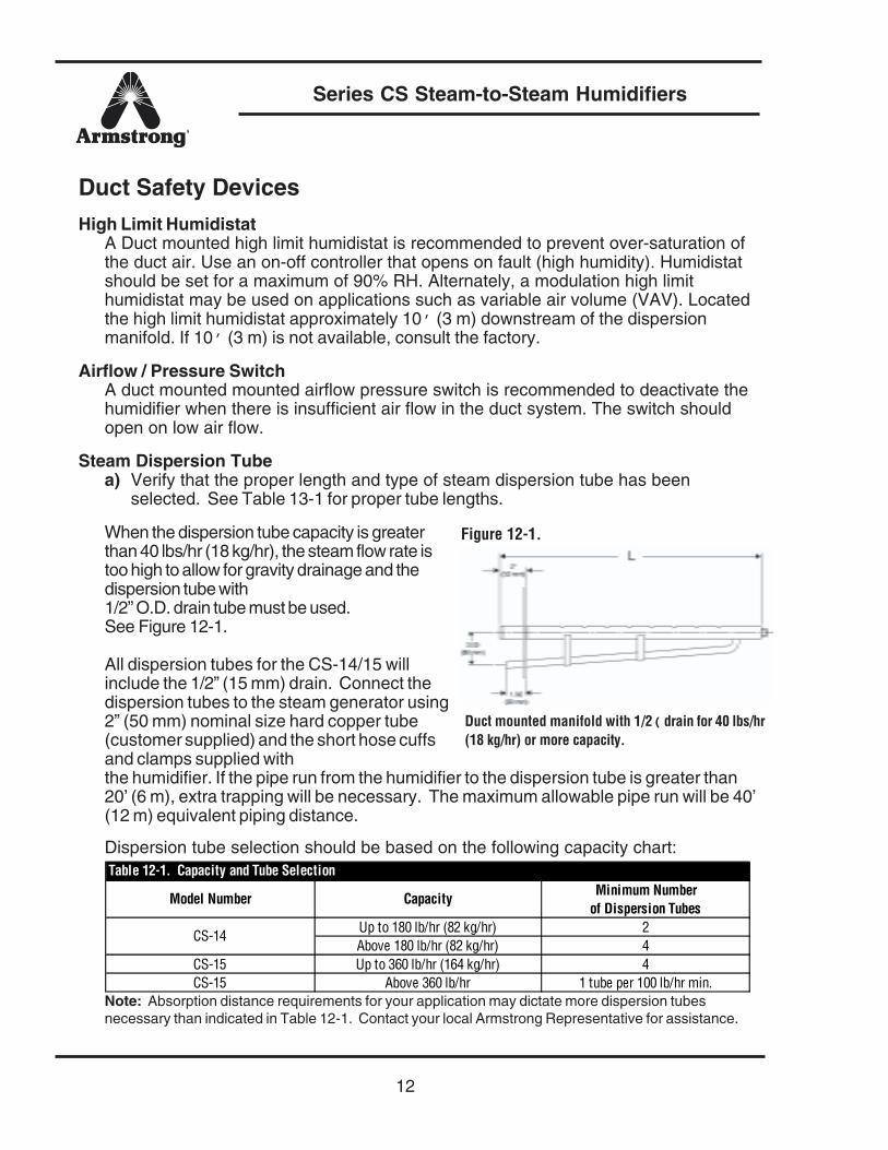
When the dispersion tube capacity is greaterthan 40 lbs/hr (18 kg/hr), the steam flow rate istoo high to allow for gravity drainage and thedispersion tube with1/2” O.D. drain tube must be used.See Figure 12-1.
All dispersion tubes for the CS-14/15 willinclude the 1/2” (15 mm) drain. Connect thedispersion tubes to the steam generator using2” (50 mm) nominal size hard copper tube(customer supplied) and the short hose cuffsand clamps supplied withthe humidifier. If the pipe run from the humidifier to the dispersion tube is greater than20’ (6 m), extra trapping will be necessary. The maximum allowable pipe run will be 40’(12 m) equivalent piping distance.
Dispersion tube selection should be based on the following capacity chart:
Note: Absorption distance requirements for your application may dictate more dispersion tubesnecessary than indicated in Table 12-1. Contact your local Armstrong Representative for assistance.
Model Number Capacity Minimum Number of Dispersion Tubes
Up to 180 lb/hr (82 kg/hr) 2Above 180 lb/hr (82 kg/hr) 4
CS-15 Up to 360 lb/hr (164 kg/hr) 4CS-15 Above 360 lb/hr 1 tube per 100 lb/hr min.
CS-14
Table 12-1. Capacity and Tube Selection
Figure 12-1.
Duct mounted manifold with 1/2( drain for 40 lbs/hr(18 kg/hr) or more capacity.
Series CS Steam-to-Steam Humidifiers
13
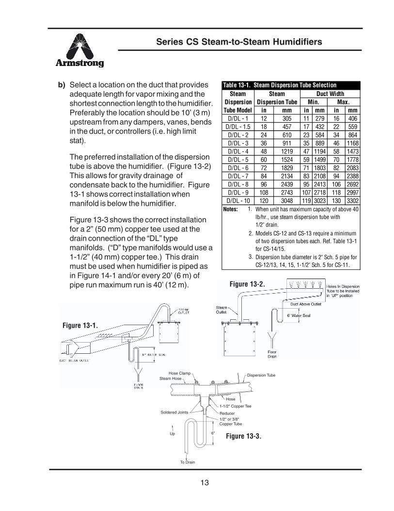
b) Select a location on the duct that providesadequate length for vapor mixing and theshortest connection length to the humidifier.Preferably the location should be 10’ (3 m)upstream from any dampers, vanes, bendsin the duct, or controllers (i.e. high limitstat).
The preferred installation of the dispersiontube is above the humidifier. (Figure 13-2)This allows for gravity drainage ofcondensate back to the humidifier. Figure13-1 shows correct installation whenmanifold is below the humidifier.
Figure 13-3 shows the correct installationfor a 2” (50 mm) copper tee used at thedrain connection of the “DL” typemanifolds. (“D” type manifolds would use a1-1/2” (40 mm) copper tee.) This drainmust be used when humidifier is piped asin Figure 14-1 and/or every 20’ (6 m) ofpipe run maximum run is 40’ (12 m).
in mm in mm in mmD/DL - 1 12 305 11 279 16 406
D/DL - 1.5 18 457 17 432 22 559D/DL - 2 24 610 23 584 34 864D/DL - 3 36 911 35 889 46 1168D/DL - 4 48 1219 47 1194 58 1473D/DL - 5 60 1524 59 1499 70 1778D/DL - 6 72 1829 71 1803 82 2083D/DL - 7 84 2134 83 2108 94 2388D/DL - 8 96 2439 95 2413 106 2692D/DL - 9 108 2743 107 2718 118 2997D/DL - 10 120 3048 119 3023 130 3302
Notes: 1.
2.
3.
When unit has maximum capacity of above 40 lb/hr., use steam dispersion tube with 1/2" drain.Models CS-12 and CS-13 require a minimum of two dispersion tubes each. Ref. Table 13-1 for CS-14/15.Dispersion tube diameter is 2" Sch. 5 pipe for CS-12/13, 14, 15, 1-1/2" Sch. 5 for CS-11.
Table 13-1. Steam Dispersion Tube SelectionDuct Width
Min. Max.Steam
Dispersion Tube Steam
Dispersion Tube Model
6"
Dispersion Tube
Hose
1-1/2" Copper Tee
Reducer
1/2" or 3/8"Copper Tube
To Drain
Up
Soldered Joints
Steam HoseHose Clamp
Figure 13-1.
Figure 13-2.
Figure 13-3.

Series CS Steam-to-Steam Humidifiers
14
c) Insert the dispersion tube into the duct so the holes face upward. NEVER install thetube with the holes facing downward. Fasten the mounting plate to the outside ofthe duct with sheet metal screws. If the dispersion tube is 36” (.3 m) long or more,support the outer end with threaded rod or similar means. Avoid installing standardmanifold in downward flow air duct or ducts where air velocity exceeds 2000 FPM.
d) For the “DL” type dispersiontubes, connect the dispersiontube to the steam generatorusing 2” (50 mm) nominal sizehard copper tube (customersupplied) and the two shorthoses supplied with thehumidifier (Figure 13-3). The“D” type requires 1-1/2” (40mm) nominal copper tube.Insulate the copper tube tominimize condensation.
For the CS-11, if the optional 10 foot (3 m) flexible steam hose is used, cut the steamhose to length as required. Wipe out the inside of each hose end before installing.Connect the cut end of the hose to the dispersion tube. Tighten all hose clamps.
Steam hose or pipe must be free of loops, kinks, and sags to allow for gravitydrainage of condensate. (Provide pitch of 1" (25 mm) per foot.) Hose supportsmay be required.
Physical Data CS-11/12/13
CS-11 CS-12 CS-132 2 4 55 10 30 5010 30 80 10013 33 105 15015 35 120 180
Maximum Operating PressureWater Supply Pressure Range
Note: Use of teflon coated heat exchanger may reduce capacity. Consult Factory.15 psi
15 - 115 psiHigher steam-to-steam humidifier capacities available from Armstrong. See Bulletin 571 and 568.
Model No.Table 14-1. Capacities and Physical Data
Steam Pressure psi
Capacities based on steam pressure, downstream of control valve. Anticipate minimum of 2 ! psi across valve.
Figure 14-1.

Series CS Steam-to-Steam Humidifiers
15
Figure 15-1.
A B C D E F G H J K L M N P R S T
CS-11 in mm
31-3/8 797
15-3/8 390
27 685
13 330
15-1/16 382
11-1/2 292
8-1/2 216
12 305
7-5/8 194
4-1/8 105
2-1/4 27
— —
2 50
4-1/2 114
6 152
1-1/2 38
15-11/16 398
CS-12 in mm
46-1/2 1181
21-5/8 549
43 1092
19 482
17-1/16 433
13-1/2 343
10-1/2 267
18 457
13-5/8 346
3-23/32 94
3-19/32 91
6 152
1 25
7-1/2 190
8 203
2-3/8 60
— —
CS-13 in mm
46-1/2 1181
21-5/8 549
43 1092
19 482
17-1/16 433
13-1/2 343
10-1/2 267
18 457
13-5/8 346
3-23/32 94
3-19/32 91
6 152
1 25
7-1/2 190
8 203
2-3/8 60
— —
Model No.
Table 15-1. Physical Data
Physical Data CS-14
These capacities are based on supply pressure to the control valve.
These capacities are based on supply pressure to the contro l valve.
Table 15-2. CapacitiesCS-15S
115 lb/hr (52 kg/hr)Inlet Pressure CS-14C CS-14S/DI CS-15C
5 psig (.35 bar) 100 lb/hr (45 kg/hr) 75 lb/hr (34 kg/hr) 200 lb/hr (91 kg/hr)135 lb/hr (61 kg/hr) 560 lb/hr (255 kg/hr) 270 lb/hr (123 kg/hr)
15 psig (1 bar) 400 lb/hr (182 kg/hr) 260 lb/hr (118 kg/hr) 800 lb/hr (364 kg/hr) 520 lb/hr (236 kg/hr)10 psig (.7 bar) 280 lb/hr (127 kg/hr)
Model No. CS-11 CS-12/CS-13 CS-14 CS-15Tank Capacity, Gallons/Liters 10 (38) 30 (114) 52 (197) 140 (530)Fill Rate, gpm (L/min) 2 (7.6) 2 (7.6) 2 (7.6) 2 (7.6)Drain Rate, gpm (L/min) 2.5 (9.5) 2.5 (9.5) 2.5 (9.5) 3 (11.5)
Tank Capacity and Fill/Drain Rates
Series CS Steam-to-Steam Humidifiers
16
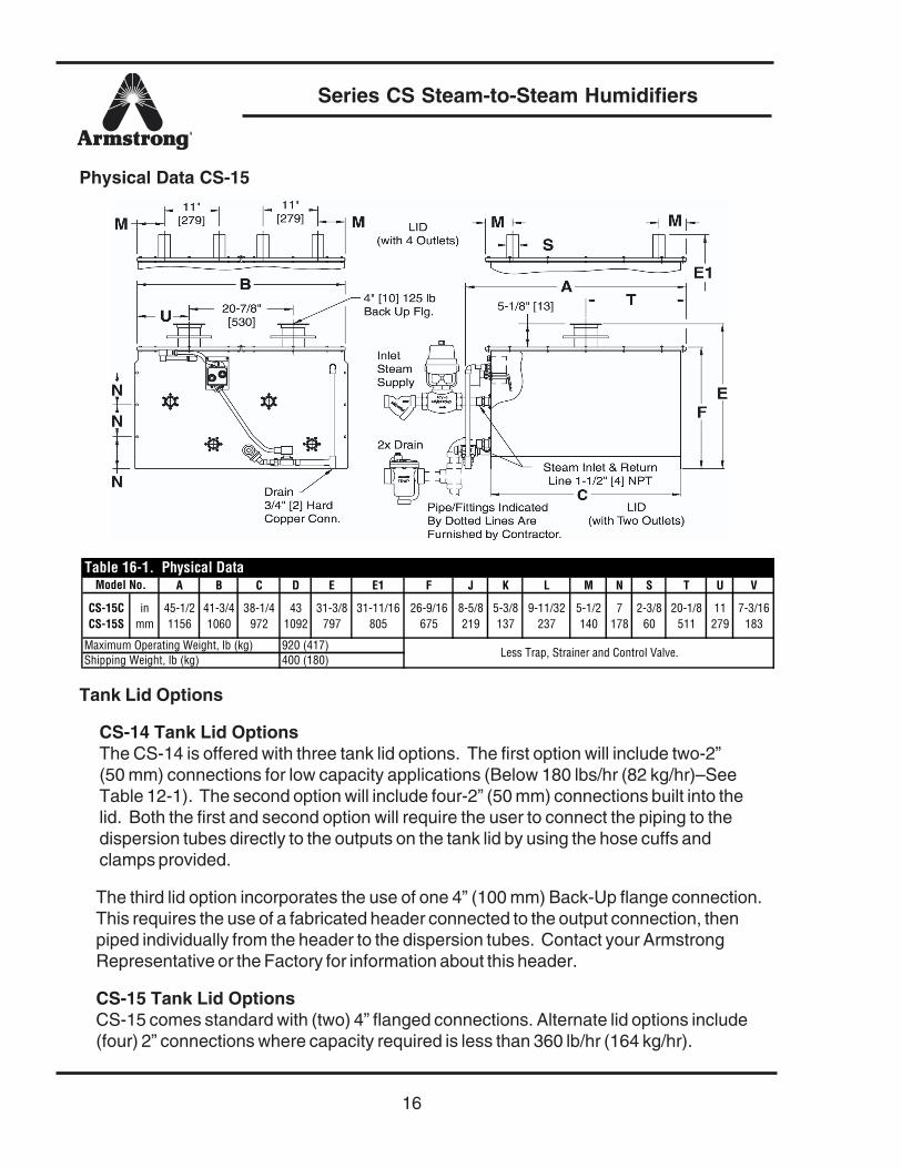
Physical Data CS-15
Tank Lid Options
CS-14 Tank Lid OptionsThe CS-14 is offered with three tank lid options. The first option will include two-2”(50 mm) connections for low capacity applications (Below 180 lbs/hr (82 kg/hr)–SeeTable 12-1). The second option will include four-2” (50 mm) connections built into thelid. Both the first and second option will require the user to connect the piping to thedispersion tubes directly to the outputs on the tank lid by using the hose cuffs andclamps provided.
The third lid option incorporates the use of one 4” (100 mm) Back-Up flange connection.This requires the use of a fabricated header connected to the output connection, thenpiped individually from the header to the dispersion tubes. Contact your ArmstrongRepresentative or the Factory for information about this header.
CS-15 Tank Lid OptionsCS-15 comes standard with (two) 4” flanged connections. Alternate lid options include(four) 2” connections where capacity required is less than 360 lb/hr (164 kg/hr).
A B C D E E1 F J K L M N S T U V
CS-15C CS-15S
in mm
45-1/2 1156
41-3/4 1060
38-1/4 972
43 1092
31-3/8 797
31-11/16 805
26-9/16 675
8-5/8 219
5-3/8 137
9-11/32 237
5-1/2 140
7 178
2-3/8 60
20-1/8 511
11 279
7-3/16 183
Model No.Table 16-1. Physical Data
Maximum Operating Weight, lb (kg)Shipping Weight, lb (kg)
920 (417)400 (180)
Less Trap, Strainer and Control Valve.

Series CS Steam-to-Steam Humidifiers
17
Principles of Operation, CS Steam-to-Steam Humidifiers
The Series CS-10 Humidifiers consists of a heat exchanger submersed in a tank ofwater. The heat of the steam supplied to the heat exchanger raises the temperature ofthe tank water to the boiling point. At this point, water is converted to live steam whichis, in turn, injected into an air handling duct. The result gives humidification withoutconcern for boiler water treatment carryover.
The Armstrong Steam Control Valve is fed either a variable pneumatic or electriccontrol signal from the controlling humidistat. This regulates humidifier output accordingto demand. Condensate flows from the heat exchanger to the steam trap before beingdischarged to the return system.
Steam output may be stopped by a duct high-limit humidistat or a fan interlock switch.These devices prevent excess moisture and condensation in the duct. Additionally, forthe Series CS-10, the steam to the heat exchanger is interrupted if a low liquid level isindicated in the chamber.
Water level in the tank is controlled by a ball float valve for the Series CS-10-SF, and byelectrode liquid level control for all other Series CS-10 Models. The electrode liquidlevel control cycles a water fill solenoid valve on/off to maintain the liquid level inside thetank.
Start-up Procedure for Series CS-10-SF Humidifiers
The following steps should be performed on all newly installed Series CShumidifiers to ensure that the humidifier and the entire humidification systemfunctions properly.
1) Check for any loose connections on the humidifier chamber and in the steam, water,and drain lines.
2) Turn on water supply to the humidifier. Check for leaks. It may take 45 minutes ormore for the unit to fill on its own. If this is not satisfactory, the unit may be openedand a water hose used to assist in the initial fill.
3) Fill the water seal in the piping downstream of the chamber overflow connection. Ifthe chamber drain piping and overflow piping are joined before the water seal, theseal is filled by momentarily opening the manual drain valve.
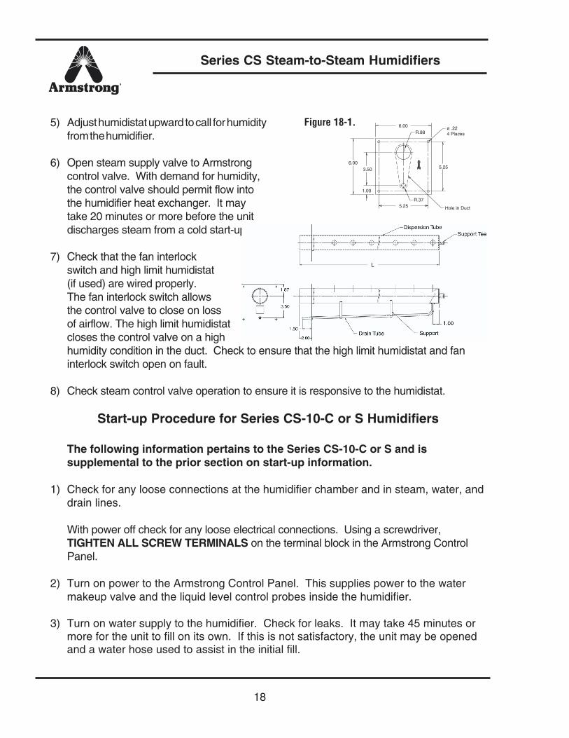
4) If the “Dispersion Tube” is equipped with a drain fitting, verify that it is working. Lookat the “Tube Mounting Plate”, there is an Armstrong “A” Logo or “UP” sticker whichshould be pointing up. If not, the tube will not drain properly. See Figure 18-1.
Series CS Steam-to-Steam Humidifiers
18
5) Adjust humidistat upward to call for humidityfrom the humidifier.
6) Open steam supply valve to Armstrongcontrol valve. With demand for humidity,the control valve should permit flow intothe humidifier heat exchanger. It maytake 20 minutes or more before the unitdischarges steam from a cold start-up.
7) Check that the fan interlockswitch and high limit humidistat(if used) are wired properly.The fan interlock switch allowsthe control valve to close on lossof airflow. The high limit humidistatcloses the control valve on a highhumidity condition in the duct. Check to ensure that the high limit humidistat and faninterlock switch open on fault.
8) Check steam control valve operation to ensure it is responsive to the humidistat.
Start-up Procedure for Series CS-10-C or S Humidifiers
The following information pertains to the Series CS-10-C or S and issupplemental to the prior section on start-up information.
1) Check for any loose connections at the humidifier chamber and in steam, water, anddrain lines.
With power off check for any loose electrical connections. Using a screwdriver,TIGHTEN ALL SCREW TERMINALS on the terminal block in the Armstrong ControlPanel.
2) Turn on power to the Armstrong Control Panel. This supplies power to the watermakeup valve and the liquid level control probes inside the humidifier.
3) Turn on water supply to the humidifier. Check for leaks. It may take 45 minutes ormore for the unit to fill on its own. If this is not satisfactory, the unit may be openedand a water hose used to assist in the initial fill.
1.00
R.37
R.88
Hole in Duct
ø .224 Places
6.00
6.00
3.50
5.25
5.25
Figure 18-1.
Series CS Steam-to-Steam Humidifiers
19
4) Fill the water seal in the piping downstream of the chamber overflow connection. If thechamber drain piping and overflow piping are joined before the water seal, the seal isfilled by momentarily opening the manual drain valve.
5) If the “Dispersion Tube” is equipped with a drain fitting, verify that it is working. Lookat the “Tube Mounting Plate”, there is an Armstrong “A” Logo or “UP” sticker whichshould be pointing up. If not, the tube will not drain properly. See Figure 18-1.
Start-up Procedure for the CS-10-CB or SB
1) Verify all wiring connections are tight and wired properly.
2) With the Steam Generation switch in the OFF position, apply power to the unit.
3) Cycle the three switches on the PC board to verify operation of the fill, drain, andtemper valve (if used).
4) Engage unit by depressing the Steam Generation switch to the ON position.
5) Verify the fill valve engages and the unit begins to fill.
6) Once the water reaches the low electrode, the control valve should open and theunit will begin its 7 minute warm up cycle. The unit will not respond to any controlsignals during this time. If troubleshooting is to be done, it is very important that allcontrol signal readings are done after this 7 minute warm up period.
7) After the 7 minute warm up period, the humidifier should go into normal operationresponding to the humidistat signal.
Maintenance Schedule
Note: CS-10 Series Humidifiers must have the power to the control panelturned off prior to opening the chamber.
One Week After Start-up
1) Check unit operation.
2) Check drain piping for leaks.
3) Check water supply piping for leaks.
4) Check steam piping for leaks.
5) Observe duct low points for signs of poor humidity distribution.

Series CS Steam-to-Steam Humidifiers
20
6) Clean Strainer. The screen in the strainer installed in the steam supply line should becleaned one a week after the humidifier has been in service. This should be repeatedonce a season thereafter—more if you find much dirt on the screen.
7) Check Trap. The steam trap used to drain the humidifier should be inspected at thesame time the strainer is cleaned.
General Maintenance
The primary source of required maintenance with the CS-10 Series will be cleaningof the chamber, heat exchanger, and float mechanism or electrodes.
Frequency of cleaning will be dependent on water quality and humidifier outputrequirements. The use of softened water will reduce the need for cleaning. For theuse of deionized, demineralized, and reverse osmosis type water, consult factory.
Inspect One Month After Start-up
Armstrong recommends a new unit be opened and inspected for solid buildup afterone month of service.
Procedure for Cleaning
1) Shut down the steam supply to the control valve, and if the unit is a CS-10 orCS-13/14/15 type, turn off power to the control box.
2) Give the humidifier some time to cool down. The inside and outside of the chamberis HOT!
3) Manually drain the chamber. For CS-10-C or S, this is done by switching by the“Manual Drain” switch on the front of the control panel to the “On” position. If theunit has a gate or ball valve plumbed in to the chamber drain, open this to aid indraining.
4) Remove the unit’s lid and flush cold water through the chamber.
5) Inspect the float mechanism or electrodes. Remove and clean if necessary.
6) If the heat exchanger is Teflon® coated, be careful not to scratch away the coatingwith sharp instruments.
Series CS Steam-to-Steam Humidifiers
21
7) All CS-10-C heat exchangers are coated with a protective electroless-nickel coating,be careful not to scratch this coating with sharp instruments. Muriatic acid can be usedper chemical manufacturer’s specification. Armstrong also offers RiteQuick, which is anon-caustic cleaning product. Please contact Armstrong or your local ArmstrongRepresentative for more information.
8) Remove any accumulation of solids from the chamber at this time.
9) Inspect heat exchanger and clean if required. Removal of solids is simplified if theaccumulation is moist and has been “shocked” with cold water not long after shutdown.
Experience with cleaning will serve as a guide as to how frequently cleaning will berequired. The optional automatic drain valve and timer package is intended toreduce the accumulation of solids in the humidifier. For units purchased without thispackage, it frequently can be added in the field.
Completing a Service Life Cycle
When the 90% of the selected service time has accumulated, the “SERVICE LIFE” LEDon the control panel will start to flash (blink on and off). See DIP Switch Settings Sec-tion. If HumidiClean is not serviced by replacing the ionic beds and manually depressingthe reset switch, HumidiClean will continue to produce steam on demand for the re-maining Service Life. During these hours of operation, the HumidiClean will display aflashing “SERVICE LIFE” LED. After 100% of the selected Service Life has accumu-lated, in hours of power to the heating elements, the unit will shut down by draining thetank as described above and not respond to any call for humidity.
Replacing the Ionic Beds
1. Turn off steam generation switch and allow unit to completely drain.
2. Cut power at circuit breaker.
3. (Caution: Tank will still be quite warm and should be allowed to cool.)Disconnect hose cuff piping from tank lid. Remove all tank lid screws and removetank lid(s).
4. Unsnap ionic beds from support pins and remove all Ionic Beds.
5. Inspect tank drain outlet and heat exchanger inside the tank. Heat exchanger mayneed to be cleaned at this time. Please refer to Cleaning Procedure on page 20 forcomplete cleaning instructions.
Series CS Steam-to-Steam Humidifiers
22
6. Install new ionic beds, snapping them into place on the support pins. Number of bedsdepends upon model number as follows:
CS-13 10 Beds Required (P/N B5213)CS-14 12 Beds Required (P/N D3337)CS-15 24 Beds Required (P/N D3337)
7. Be sure tank gasket is lapped over all edges of tank lid connection. Replaceand secure tank lid.
8. Reconnect steam dispersion hose cuff piping.
9. Turn on power at circuit breaker.
10.Depress and hold in the reset button to the left for 20 seconds. All the LED’s willblink together indicating the accumulated hours memory has been reset to zero. Theunit should now be heard filling. NOTE: The accumulated time memory can only bereset to zero when the service LED is blinking or on solid.
11.The following step should be performed after the unit has started heating and ismaking steam. Turn main power off and double check tank lid gasket for steamleakage. Re-tighten tank lid screws or reposition gasket if necessary.
Troubleshooting Guide
I. Humidifier will not discharge steam.A. Control System Fault
1. Control valve operator – Does the valve open and close as the controlsignal varies between 0% to 100%?
2. Humidity controller – Does the control signal coming to the humidifierreflect the relative humidity set point on the controller?
3. Connections between humidity controller and control valve – Is therecontinuity, and is the same signal measured at the humidifier connectionsand controller connections alike?
4. Safety controls open – High limit, fan interlock, etc.B. Steam System Malfunction
1. Lift or back pressure after steam trap is too great for steam supplypressure resulting in a flooded humidifier heat exchanger.
2. Strainer screen before control valve is plugged.3. Steam valve closed in line to humidifier—See Section I-A above for
possible causes.4. Pressure reducing valve malfunction.5. Steam trap has failed closed.6. Low liquid level in chamber—See Section I-C on Page 23.
Series CS Steam-to-Steam Humidifiers
23
C. Water Supply Malfunction1. Low or no water pressure.2. Plugged valve or water strainer.3. Faulty water fill valve – For Series CS-10-C or S, is there power to the
control box and solenoid fill valve?4. Electrodes possibly need cleaning.
II. Humidifier Discharges Continuously Even Though Humidity Has ReachedDesired Level.A. Humidity controller out of calibration.B. Humidifier malfunction.
1. Valve stem on control valve “frozen” to stem seal due to unusual chemicalor corrosive conditions in steam system.
2. Operator spring on pneumatic control valve broken.3. Dirt or scale between valve and seat in control valve—blow down and
clean strainer.
III. Humidifier Does Not Stop FillingA. Float mechanism may be failed open.B. The fill valve is stuck open or does not seat properly.C. Water pressure too high (above 75 psi).D. The electrodes need cleaning.E. Loose connection on wiring from control box to electrode.
IV. Low Steam OutputA. Control System.
1. Humidity controller not calibrated or malfunctioning.2. Control valve faulty.
B. Steam System.1. Low steam pressure.2. Steam supply strainer plugged.3. Wrong steam trap used—Always use properly sized Armstrong inverted
bucket steam trap.4. Heat exchanger needs to be cleaned.5. Flooded heat exchanger because of too much vertical lift after steam trap
— or high back pressure in return line.C. Water Level Control.
1. Low water pressure.2. Faulty water fill valve.
Series CS Steam-to-Steam Humidifiers
24
V. Humidifier Discharges WaterA. Distance too great between humidifier and duct (more than 40 ft equivalentpiping distance).B. Check for improper pitch or low points in steam pipe from humidifier to duct.C. Manifold not dripped.D. Steam pressure too high.
For additional information on Armstrong Series CS-10-CB or SB Humidifiers only,contact Armstrong or your local Representative.
Diagnostics (Series CS-10-CB or SB only)
There are some diagnostic routines programmed into the PC board. If these routinesdetect a problem the unit will shut down and flash the “ERROR” LED a certain numberof times, followed by a long pause.
1 Blink — The low level switch has not closed after 60 minutes of fill valve on time.This is only on initial start-up or after a complete drain down.Check: defective fill valve, debris in fill valve inlet screen or on tank drain screen,water leakage from tank or inlet tubing, no water flow or low water pressure, drainvalve stuck open or leaking, defective low water level switch (electrodes need tobe cleaned).
2 Blinks — The low level switch has not closed after 12 minutes of fill valve on time.This is only after initial start-up fill and boil-down sequence.Check: debris in water switch canister, defective fill valve, no water flow or lowwater pressure, drain valve stuck open, defective low water level switch(electrodes need to be cleaned).
3 Blinks — The high level switch has not closed after 20 minutes of fill on time. This isonly on initial start-up or after a complete drain down.Check: debris in fill valve inlet screen or in tank drain screen, water leaking from tankor inlet tubing, low water pressure, defective high water level switch (electrodes needto be cleaned).
4 Blinks — The high water switch is still closed 18 minutes after the fill valve has turnedoff upon hitting the high water level and a 10 minute drain does not drop the waterbelow the high water level.Check: defective high water level switch, debris in level canister, fill valve stuck open,drain valve is defective or scale buildup in drain line.
Series CS Steam-to-Steam Humidifiers
25
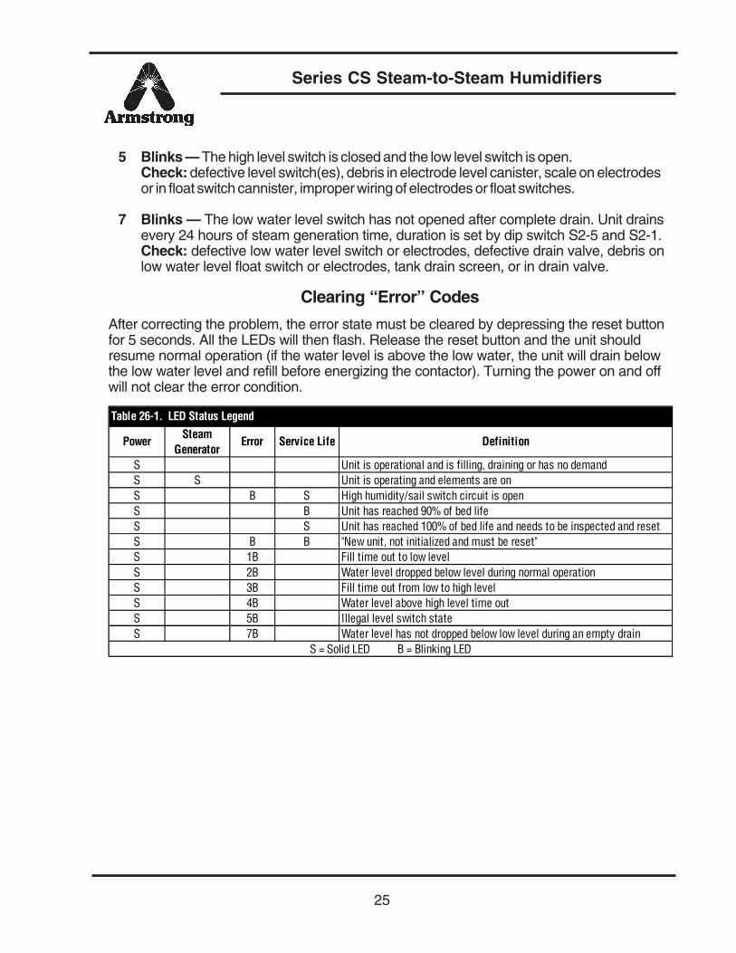
5 Blinks — The high level switch is closed and the low level switch is open.Check: defective level switch(es), debris in electrode level canister, scale on electrodesor in float switch cannister, improper wiring of electrodes or float switches.
7 Blinks — The low water level switch has not opened after complete drain. Unit drainsevery 24 hours of steam generation time, duration is set by dip switch S2-5 and S2-1.Check: defective low water level switch or electrodes, defective drain valve, debris onlow water level float switch or electrodes, tank drain screen, or in drain valve.
Clearing “Error” Codes
After correcting the problem, the error state must be cleared by depressing the reset buttonfor 5 seconds. All the LEDs will then flash. Release the reset button and the unit shouldresume normal operation (if the water level is above the low water, the unit will drain belowthe low water level and refill before energizing the contactor). Turning the power on and offwill not clear the error condition.
Power Steam Generator
Error Service Life Definition
S Unit is operational and is filling, draining or has no demandS S Unit is operating and elements are onS B S High humidity/sail switch circuit is openS B Unit has reached 90% of bed lifeS S Unit has reached 100% of bed life and needs to be inspected and resetS B B "New unit, not initialized and must be reset"S 1B Fill time out to low levelS 2B Water level dropped below level during normal operationS 3B Fill time out from low to high levelS 4B Water level above high level time outS 5B Illegal level switch stateS 7B Water level has not dropped below low level during an empty drain
Table 26-1. LED Status Legend
S = Solid LED B = Blinking LED
Series CS Steam-to-Steam Humidifiers
26
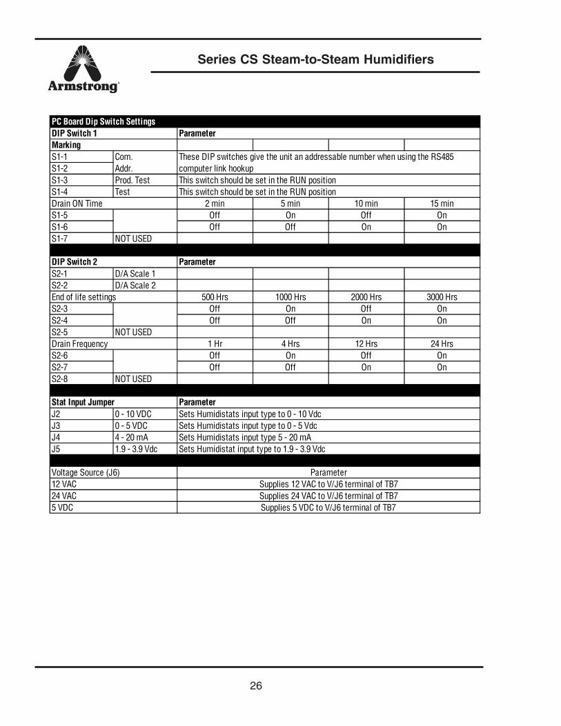
S1-1S1-2S1-3 Prod. TestS1-4 Test
2 min 5 min 10 min 15 minS1-5 Off On Off OnS1-6 Off Off On OnS1-7 NOT USED
S2-1 D/A Scale 1S2-2 D/A Scale 2
500 Hrs 1000 Hrs 2000 Hrs 3000 HrsS2-3 Off On Off OnS2-4 Off Off On OnS2-5 NOT USED
1 Hr 4 Hrs 12 Hrs 24 HrsS2-6 Off On Off OnS2-7 Off Off On OnS2-8 NOT USED
J2 0 - 10 VDCJ3 0 - 5 VDCJ4 4 - 20 mAJ5 1.9 - 3.9 Vdc
12 VAC24 VAC5 VDC
ParameterSupplies 12 VAC to V/J6 terminal of TB7Supplies 24 VAC to V/J6 terminal of TB7Supplies 5 VDC to V/J6 terminal of TB7
Sets Humidistats input type 5 - 20 mASets Humidistat input type to 1.9 - 3.9 Vdc
Voltage Source (J6)
Stat Input Jumper ParameterSets Humidistats input type to 0 - 10 VdcSets Humidistats input type to 0 - 5 Vdc
Drain Frequency
DIP Switch 2 Parameter
End of life settings
Drain ON Time
Com. Addr.
These DIP switches give the unit an addressable number when using the RS485 computer link hookupThis switch should be set in the RUN positionThis switch should be set in the RUN position
PC Board Dip Switch SettingsDIP Switch 1 ParameterMarking

Series CS Steam-to-Steam Humidifiers
27
Notes
IB-87-D 2M 3/04
Armstrong Humidification Group816 Maple Street, P.O. Box 408, Three Rivers, MI 49093 - USA Phone: (269) 273-1415 Fax: (269) 273-9500Parc Industriel Des Hauts-Sarts, B-4040 Herstal/Liege, Belgium Phone: (04) 2409090 Fax:(616) 2481361Steam Traps \ Humidifiers \ Steam Coils \ Valves \ Water Heaters \ Pumping Traps \ Hose Stationswww.armstrong-intl.com
©2004 Armstrong International, Inc.Designs, materials and performance ratings are
subject to change without notice.
Printed in USA
Armstrong International, Inc.Limited Warranty and Remedy
Armstrong International, Inc. (“Armstrong”) warrants to the original user of those products suppliedby it and used in the service and in the manner for which they are intended, that such products shall befree from defects in material and workmanship for a period of one (1) year from the date of installation, butnot longer than 15 months from the date of shipment from the factory, [unless a Special Warranty Periodapplies, as listed below]. This warranty does not extend to any product that has been subject to misuse,neglect or alteration after shipment from the Armstrong factory. Except as may be expressly provided in awritten agreement between Armstrong and the user, which is signed by both parties, Armstrong DOESNOT MAKE ANY OTHER REPRESENTATIONS OR WARRANTIES, EXPRESS OR IMPLIED, INCLUD-ING, BUT NOT LIMITED TO, ANY IMPLIED WARRANTY OF MERCHANTABILITY OR ANY IMPLIEDWARRANTY OF FITNESS FOR A PARTICULAR PURPOSE.
The sole and exclusive remedy with respect to the above limited warranty or with respect to anyother claim relating to the products or to defects or any condition or use of the products supplied byArmstrong, however caused, and whether such claim is based upon warranty, contract, negligence, strictliability, or any other basis or theory, is limited to Armstrong’s repair or replacement of the part or product,excluding any labor or any other cost to remove or install said part or product, or at Armstrong’s option, torepayment of the purchase price. As a condition of enforcing any rights or remedies relating to Armstrongproducts, notice of any warranty or other claim relating to the products must be given in writing to Arm-strong: (i) within 30 days of last day of the applicable warranty period, or (ii) within 30 days of the date ofthe manifestation of the condition or occurrence giving rise to the claim, whichever is earlier. IN NOEVENT SHALL ARMSTRONG BE LIABLE FOR SPECIAL, DIRECT, INDIRECT, INCIDENTAL ORCONSEQUENTIAL DAMAGES, INCLUDING, BUT NOT LIMITED TO, LOSS OF USE OR PROFITS ORINTERRUPTION OF BUSINESS. The Limited Warranty and Remedy terms herein apply notwithstandingany contrary terms in any purchase order or form submitted or issued by any user, purchaser, or thirdparty and all such contrary terms shall be deemed rejected by Armstrong.
Special Warranty Periods are as follows:
Series EHU-700 Electric Steam Humidifier, Series HC-4000 HumidiClean Humidifier andGFH Gas Fired Humidifier with Ionic Beds:Two (2) years after installation, but not longer than 27 months after shipment from Armstrong’s factory.