INSTALLATION AND MAINTENANCE … AND MAINTENANCE INSTRUCTIONS 4HP16LT Series Split System Heat Pump...
30
Save these instructions for future reference 506468-01 Page 1 Risk of electrical shock. Disconnect all remote power supplies before installing or servicing any portion of the system. Failure to disconnect power supplies can result in property damage, personal injury, or death. WARNING Installation and servicing of air conditioning equipment can be hazardous due to internal refrigerant pressure and live electrical components. Only trained and qualified service personnel should install or service this equipment. Installation and service performed by unqualified persons can result in property damage, personal injury, or death. WARNING Sharp metal edges can cause injury. When installing the unit, use care to avoid sharp edges. WARNING The equipment covered in this manual is to be installed by trained and experienced service and installation technicians. Improper installation, modification, service, or use can cause electrical shock, fire, explosion, or other conditions which may cause personal injury, death, or property damage. Use appropriate safety gear including safety glasses and gloves when installing this equipment. WARNING INSTALLATION AND MAINTENANCE INSTRUCTIONS 4HP16LT Series Split System Heat Pump Issue 1004 Manufactured By Allied Air Enterprises, Inc. A Lennox International Inc. Company 215 Metropolitan Drive West Columbia, SC 29170 TABLE OF CONTENTS INSTALLATION ...................................... 2 CONNECTION DIAGRAM ..................... 4 START-UP ............................................ 13 OPERATION ........................................ 18 MAINTENANCE ................................... 23 *506468-01*
-
Upload
trinhkhanh -
Category
Documents
-
view
218 -
download
1
Transcript of INSTALLATION AND MAINTENANCE … AND MAINTENANCE INSTRUCTIONS 4HP16LT Series Split System Heat Pump...

Save these instructions for future reference
506468-01 Page 1
Risk of electrical shock. Disconnect all remotepower supplies before installing or servicingany portion of the system. Failure todisconnect power supplies can result inproperty damage, personal injury, or death.
WARNING
Installation and servicing of air conditioningequipment can be hazardous due to internalrefrigerant pressure and live electricalcomponents. Only trained and qualified servicepersonnel should install or service thisequipment. Installation and service performedby unqualified persons can result in propertydamage, personal injury, or death.
WARNING
Sharp metal edges can cause injury. Wheninstalling the unit, use care to avoid sharpedges.
WARNING
The equipment covered in this manual is to be installed by trained and experienced serviceand installation technicians. Improper installation, modification, service, or use can causeelectrical shock, fire, explosion, or other conditions which may cause personal injury, death,or property damage. Use appropriate safety gear including safety glasses and gloves wheninstalling this equipment.
WARNING
INSTALLATION AND MAINTENANCE INSTRUCTIONS
4HP16LT SeriesSplit System Heat Pump
Issue 1004
Manufactured ByAllied Air Enterprises, Inc.
A Lennox International Inc. Company215 Metropolitan Drive
West Columbia, SC 29170
TABLE OF CONTENTS
INSTALLATION ...................................... 2
CONNECTION DIAGRAM ..................... 4
START-UP ............................................ 13
OPERATION ........................................ 18
MAINTENANCE ................................... 23
*506468-01*

Page 2 Issue 1004 506468-01
INSTALLATION on the carrier’s freight bill. Take special care to examinethe unit inside the carton if the carton is damaged. Anyconcealed damage discovered should be reported to thelast carrier immediately, preferably in writing, and shouldinclude a request for inspection by the carrier’s agent.
If any damages are discovered and reported to the carrierDO NOT INSTALL THE UNIT, as claim may be denied.Check the unit rating plate to confirm specificationsare as ordered.
Location of Unit
Outdoor units operate under a wide range of weatherconditions; therefore, multiple factors must be consideredwhen positioning the unit. The unit must be positioned togive adequate clearances for sufficient airflow and servic-ing. Refer to Figure 1 for installation clearances.
General
Read this entire instruction manual, as well as theinstructions supplied in separate equipment, beforestarting the installation. Observe and follow all warn-ings, cautions, instructional labels, and tags. Failureto comply with these instructions could result in anunsafe condition and/or premature component failure.
These instructions are intended as a general guide only foruse by qualified personnel and do not supersede any nationalor local codes in any way. The installation must comply with allprovincial, state, and local codes as well as the NationalElectrical Code (U.S.) or Canadian Electrical Code (Canada).Compliance should be determined prior to installation.
4HP16LT condensing units use R410A which is anozone-friendly HFC refrigerant. This unit must be installedwith a matching indoor coil and line set. A filter drierapproved for use with 410A is installed in the unit.
IMPORTANT: This product has been designed and manu-factured to meet ENERGY STAR criteria for energy effi-ciency when matched with appropriate coil components.However, proper refrigerant charge and proper air flow arecritical to achieve rated capacity and efficiency. Installationof this product should follow the manufacturer’s refrigerantcharging and air flow instructions. Failure to confirmproper charge and airflow may reduce energy effi-ciency and shorten equipment life.
When servicing or repairing HVAC components, ensurethe fasteners are appropriately tightened. Table 1 showstorque values for fasteners.
Inspection of Shipment
Upon receipt of equipment, carefully inspect it for possibleshipping damage. If damage is found, it should be noted
Torque Table
Table 1
renetsaF euqroT
spaCmetS .sbl.tf8
spaCtroPecivreS .sbl.tf8
swercSlateMteehS .sbl.ni61
swercSenihcaM8# .sbl.ni61
swercSenihcaM01# .sbl.ni82
stloBrosserpmoC .sbl.ni09
Figure 1
Installation Clearances
* A service clearance of 30" must be maintained onone of the sides adjacent to the control box.Clearance to one of the other three sides must be36". Clearance to one of the remaining two sidesmay be 12" and the final side may be 6".
A clearance of 24" must be maintained between units.
48" clearance required on top of unit. Maximum soffitoverhang is 36".
36 *�
36�
36�36 *�
• Place a sound-absorbing material, such as Isomode,under the unit if it will be installed in a location orposition that will transmit sound or vibration to theliving area or adjacent buildings.
• Install the unit high enough above the ground or roofto allow adequate drainage of defrost water andprevent ice buildup.
• In heavy snow areas, do not locate the unit wheredrifting snow will occur. The unit base should beelevated above the depth of average snows.

506468-01 Issue 1004 Page 3
NOTE: Elevation of the unit may be accomplished byconstructing a frame using suitable materials. If asupport frame is constructed, it must not block drainholes in unit base.
• When installed in areas where low ambient tempera-tures exist, locate unit so winter prevailing winds donot blow directly into outdoor coil.
• Locate unit away from overhanging roof lines which wouldallow water or ice to drop on, or in front of, coil or into unit.
Slab Mounting
When installing a unit at grade level, install on level slabhigh enough above grade so that water from higher groundwill not collect around the unit (see Figure 2).
Roof Mounting
Install unit at a minimum of 6" above surface of the roof toavoid ice buildup around the unit. Locate the unit above aload bearing wall or area of the roof that can adequatelysupport the unit. Consult local codes for rooftop applications.
Electrical Wiring
All field wiring must be done in accordance with theNational Electrical Code (NEC) recommendations,Canadian Electrical Code (CEC) and CSA Standards, orlocal codes, where applicable.
Refer to the furnace or blower coil Installation Instructionsfor additional wiring application diagrams and refer to unitrating plate for minimum circuit ampacity and maximumovercurrent protection size.
1. Install line voltage power supply to unit from a properlysized disconnect switch. Any excess high voltage fieldwiring should be trimmed or secured away from thelow voltage field wiring.
2. Ground unit at unit disconnect switch or to an earthground. To facilitate conduit, a hole is in the bottom of thecontrol box. Connect conduit to the control box using aproper conduit fitting. Units are approved for use only withcopper conductors. 24V Class II circuit connections aremade in the low voltage junction box. A complete unitwiring diagram is located inside the unit control box cover(see also page 26 of this instruction).
3. Install room thermostat on an inside wall that is notsubject to drafts, direct sunshine, or other heat sources.
4. Install low voltage wiring from outdoor to indoor unitand from thermostat to indoor unit (see Figure 3 onpage 4).
5. Do not bundle any excess 24V control wire inside controlbox. Run control wire through installed wire tie and tightenwire tie to provide low voltage strain relief and to maintainseparation of field-installed low and high voltage circuits.
Line voltage is present at all componentswhen unit is not in operation on units withsingle pole contactors. Disconnect all remoteelectric power supplies before opening accesspanel. Unit may have multiple power supplies.Failure to disconnect all power supplies couldresult in personal injury or death.
WARNING
Refrigerant Piping
Unit must be grounded in accordance withnational and local codes. Failure to ground unitproperly can result in personal injury or death.
WARNING
Figure 2
Slab Mounting
Discharge Air
Mounting Slab
Ground Level
BuildingStructure
Refrigerant can be harmful if inhaled. Refrigerantmust always be used and recovered responsibly.Incorrect or irresponsible use of refrigerant canresult in personal injury or death.
WARNING
If the 4HP16LT unit is being installed with a new indoorcoil and line set, the refrigerant connections should bemade as outlined in this section. If an existing line set and/or indoor coil will be used to complete the system, refer to

506468-01Page 4 Issue 1004
this sesction as well as the section that follows entitledFlushing Existing Line Set and Indoor Coil.
If this unit is being matched with an approved line set orindoor coil which was previously charged with R-22refrigerand, the line set and coil must be flushed prior toinstallation. If the unit is being used with an exisitng indoorcoil which was equipped with a liquid line which served as ametering device (RFCI), the liquid line must be replaced priorto the installation of the 4HP16LT unit.
Field refrigerant piping consists of liquid and suction linesfrom the outdoor unit (sweat connections) to the indoor coil(flare or sweat connections).
Select line set diameters from Table 2 to ensure that oilreturns to the compressor. Size vertical suction riser tomaintain minimum velocity at minimum capacity.Recommended line length is 50’ or less. If more than 50’line set is required, contact Technical Services.
Table 2 shows the diameters for line sets up to 100’ althoughvertical lift applications and trapping requirements need tobe reviewed with Technical Services for line sets over 50’.
Refrigerant Line Set Diameters (in.)
For installations exceeding 50’, contactTechnical Services.
Table 2
S uction L ine
B T UHL ine S et Length and S ize
12 ft. 25 ft. 50 ft. 75 ft. 100 ft.
3/4 3/424,000 7/8
36,000
7/8
7/8
7/8
1-1/8
7/8
7/8
1-1/848,000
7/87/8
7/8
1-1/8
1-1/8
60,000 1-1/8
1-1/8
7/8
1-1/8 1-1/8
L iquid L ine
B T UHL ine S et Length and S ize
12 ft. 25 ft. 50 ft. 75 ft. 100 ft.
3/8 3/8 3/8 3/8 3/824,000
3/8 3/8 3/8 3/8
3/8 3/8 3/8 1/2
36,000
3/8 3/8 3/8 1/2
48,000
60,000 1/2
1/2
1/2
Figure 3
Thermostat Designations(Some connections may not apply. Refer to
specific thermostat and indoor unit.)
Without Auxiliary Heat
With Auxiliary Heat
Do not connect C (common) connection between indoor unit andthermostat except when required by the indoor thermostat. Refer tothermostat installation instructions. C (common) connection betweenindoor unit and outdoor unit required for proper operation.

506468-01 Issue 1004 Page 5
Outside Unit Placementand Installation
Figure 4
Polyol ester (POE) oils used with R410Arefrigerant absorb moisture very quickly. It isvery important that the refrigerant system bekept closed as much as possible. DO NOTremove line set caps or service valve stubcaps until ready to make connections.
WARNING
Installing Refrigerant Line
During the installation of an air conditioning system, it isimportant to properly isolate the refrigerant line to preventunnecessary vibration. Line set contact with the structure(wall, ceiling, or floor) may cause objectionable noisewhen vibration is translated into sound. As a result, moreenergy or vibration can be expected. Close attention toline set isolation must be observed.
Following are some points to consider when placing andinstalling a high-efficiency outdoor unit:
Placement
Be aware that some localities are adopting sound ordinancesbased on how noisy the unit is at the neighbor’s home, not atthe original installation. Install the unit as far as possible fromthe property line. When possible, do not install the unitdirectly outside a bedroom window. Glass has a very highlevel of sound transmission. Figure 4 shows how to place theoutdoor unit and line set to reduce line set vibration.
Line Set Isolation
Illustrations on pages 6 and 7 demonstrate procedureswhich ensure proper refrigerant line set isolation. Figure 5shows how to install line sets on horizontal runs. Figure 6shows how to make a transition from horizontal to vertical.Figure 7 shows how to install line sets on vertical runs.
Brazing Connection Procedure
1. Cut ends of refrigerant lines square (free from nicksor dents). Debur the ends. The pipe must remainround; do not pinch end of line.
2. Before making line set connections, use dry nitrogen topurge the refrigerant piping. This will help to preventoxidation and the introduction of moisture into the system.
3. Use silver alloy brazing rods (5% or 6% silver alloy forcopper-to-copper brazing or 45% silver alloy forcopper-to-brass or copper-to-steel brazing) which arerated for use with R410A refrigerant.
4. Remove the Schrader core assemblies before brazingto protect them from damage due to extreme heat.Replace the cores when brazing is complete.
5. Remove light maroon washers from service valves andshield light maroon stickers to protect them duringbrazing. Wrap a wet cloth around the valve body andcopper tube stub to protect it from heat damage.
6. Braze the line set to the service valve. Quench the jointswith water or a wet cloth to prevent heat damage to thevalve core and opening port. The tube end must staybottomed in the fitting during final assembly toensure proper seating, sealing, and rigidity.
7. Install a thermal expansion valve (which is soldseparately and which is approved for use with R410Arefrigerant) in the liquid line at the indoor coil (seeRefrigerant Metering Device on page 9).
Install unit awayfrom windows
Two 90° elbows installed in linesetwill reduce lineset vibration
Page 6 Issue 1004 506468-01
Figure 6
Refrigerant Line Sets: Transition from Vertical to Horizontal
AnchoredHeavy Nylon
Wire Tie
WallStud
Metal SleeveVapor Line Wrapped
in Armaflex–
Liquid Line
WallStud
AutomotiveMuffler-Type
Hanger
Strap LiquidLine to VaporLine
Metal SleeveVapor Line Wrapped
in Armaflex–
Liquid Line
Strap LiquidLine to VaporLine
Figure 5
To hang line set from joist or rafter,use either metal strapping materialor anchored heavy nylon wire ties.
Strapping Material(around vapor line only)
8’
8’
Tape or Wire Tie
Strap the vapor line to the joist or rafterat 8 intervals then strap the liquid lineto the vapor line.
’
Floor Joist orRoof Rafter
Metal Sleeve
Floor Joist or Roof Rafter
Tape or Wire Tie
Wire Tie(around vapor line only)
Refrigerant Line Sets: Installing Horizontal Runs

506468-01 Issue 1004 Page 7
Figure 7
Refrigerant Line Sets: Installing Vertical Runs (new construction shown)
Outside Wall
Wood BlockBetween Studs
IMPORTANT: Refrigerantlines must not contact wall.
Vapor Line Liquid Line
Wire Tie
Inside Wall
Strap
Sleeve
Wire Tie
Wire Tie
Strap
Wood Block
Sleeve
Vapor Line Wrappedwith Armaflex
Liquid Line
Caulk
PVC Pipe FiberglassInsulation
Outside WallIMPORTANT:
Refrigerantlines must not
contact structure.
NOTE: Similar installation practicesshould be used if line set is to beinstalled on exterior of outside wall.
Flushing Existing Line Set and Indoor Coil
This procedure should not be performed on systemswhich contain contaminants, such as compressorburn out.
Required Equipment
The following equipment is needed to flush the existingline set and indoor coil (see Figure 8 on page 8): Twoclean R22 recovery bottles, an oil-less recovery machine
When flushing existing line set and/or indoorcoil, be sure to empty all existing traps. Residualmineral oil can act as an insulator, preventingproper heat transfer. It can also clog the thermalexpansion valve, reducing system performanceand capacity. Failure to properly flush system asexplained in these instructions will void warranty.
CAUTION
with a “pump down” feature, and two sets of gauges (onefor use with R22 and one for use with R410A).
Flushing Procedure
IMPORTANT: The line set and/or indoor coil must beflushed with at least the same amount of refrigerant thatpreviously charged the system. Check the charge in theflushing cylinder before flushing the unit.
1. Remove existing R22 refrigerant using the appropriateprocedure.
If the existing outdoor unit is not equipped with shutoffvalves, or if the unit is not operational AND the existingR22 refrigerant will be used to flush the system:
Disconnect all power to the existing outdoor unit.Connect the existing unit, a clean recovery cylinder, andthe recovery machine according to the instructionsprovided with the recovery machine. Remove all R22refrigerant from the existing system. Refer to thegauges after shutdown to confirm that the entire systemis completely void of refrigerant. Disconnect the liquidand suction lines from the existing outdoor unit.

Page 8 Issue 1004 506468-01
If the existing outdoor unit is equipped with manualshutoff valves AND new R22 refrigerant will be usedto flush the system:
Start the existing R22 refrigerant system in cooling modeand close the liquid line valve. Pump all the existing R22refrigerant back into the outdoor unit.
(It may be necessary to bypass the low pressureswitches to ensure complete refrigerant evacuation.)
When the low side system pressures reach 0 psig, closethe suction line valve. Disconnect all power to theexisting outdoor unit. Refer to the gauges after shutdownto confirm that the valves are not allowing refrigerant toflow back into the low side of the system. Disconnect theliquid and suction lines from the existing outdoor unit.
2. Remove the existing outdoor unit. Set the new R410Aunit and follow the brazing connection procedureoutlined previously on this page to make line setconnections. Do not install the R410A thermalexpansion valve at this time.
3. Make low voltage and line voltage connections to thenew outdoor unit. Do not turn on power to the unit oropen the outdoor unit service valves at this time.
4. Remove the existing R-22 refrigerant flow controlorifice or thermal expansion valve before continuingwith flushing procedures. R-22 flow control devices
are not approved for use with R410A refrigerant andmay prevent proper flushing. Use a field-providedfitting to reconnect the lines.
5. Remove the pressure tap valve cores from the4HP16LT unit’s service valves. Connect an R-22cylinder with clean refrigerant to the suction servicevalve. Connect the R-22 gauge set to the liquid linevalve and connect a recovery machine with an emptyrecovery tank to the gauge set.
6. Set the recovery machine for liquid recovery and startthe recovery machine. Open the gauge set valves toallow the recovery machine to pull a vacuum on theexisting system line set and indoor coil.
7. Invert the cylinder of clean R-22 and open its valve toallow liquid refrigerant to flow into the system throughthe suction line valve. Allow the refrigerant to passfrom the cylinder and through the line set and theindoor coil before it enters the recovery machine.
8. After all of the liquid refrigerant has been recovered,switch the recovery machine to vapor recovery so thatall of the R-22 vapor is recovered. Allow the recoverymachine to pull a vacuum on the system.
NOTE: A single system flush should remove all of themineral oil from the existing refrigerant lines and indoorcoil. A second flushing may be done (using cleanrefrigerant) if insufficient amounts of mineral oil were
Figure 8
Flushing Connections
Note: The inverted R22 cylinder must containat least the same amount of refrigerantas was recovered from the existingsystem.

removed during the first flush. After each system flush,allow the recovery machine to pull a vacuum on thesystem at the end of the procedure.
9. Close the valve on the inverted R22 cylinder and thegauge set valves. Pump the remaining refrigeraant out ofthe recovery machine and turn the machine off.
10. Use nitrogen to break the vacuum on the refrigerantlines and indoor coil before removing the recovery machine,gauges, and R22 refrigerant drum. Re-install pressure tapvalve cores into the 4HP16LT unit’s service valves.
11. Install a thermal expansion valve approved for use withR410a refrigerant in the liquid line at the indoor coil.
Refrigerant Metering Device
4HP16LT units are designed for use with TXV systems only.An R410a system will not operate properly with an R22metering device.
Expansion valves equipped with Chatleff-type fittings areavailable from the manufacturer. See Table 3 for properTXV for each unit.
To install an expansion valve (See Figure 9):
1. Separate the distributor assembly and remove the pistonorifice and used teflon seal. Insert nozzle end of theexpansion valve along with a new teflon seal into thedistributor and tighten to 20 - 30 ft. lbs. Use backup wrenchon all wrench flats. Overtightening will crush the teflonseal and may cause a leak.
2. Attach liquid line portion of distributor assembly alongwith new teflon seal to the inlet of the expansion valve.Tighten to 20 - 30 ft. lbs. Use backup wrench on all wrenchflats. Overtightening will crush the teflon seal and maycause a leak.
3. Connect the external equalizer line to the equalizer porton the suction line and tighten to 8 ft.lbs.
506468-01 Page 9Issue 1004
Table 3
TXV Data
MODEL PART NUMBER
4HP16LT- 24
4HP16LT - 36
H4TXV01
H4TXV02
4HP16LT - 48, -60 H4TXV03
4. Strap the superheat sensing bulb to the suction header.
If installing an expansion valve on an indoor coil thatpreviously used a fixed orifice, be sure to remove the existingfixed orifice. Failure to remove a fixed orifice when installingan expansion valve to the indoor coil will result in improperoperation and damage to the system.
Manifold Gauge Set
Manifold guage sets used with systems charged with R410Arefrigerant must be capable of handling the higher systemoperating pressures. The gauges should be rated for usewith pressures 1 - 800 on the high side and a low side of 30”vacuum to 250 psi with dampened speed to 500 psi. Gaugehoses must be rated for use at up to 800 psi of pressurewith a 4000 psi burst rating.
Liquid and Suction Line Service Valves
The liquid line and suction line service valves (See Figure11) and service ports are used for leak teating, evacuation,charging, and checking charge.
Each valve is equipped with a service port which has afactory-installed Schrader valve. A service port cap protectsthe Schrader valve from contamination and serves as theprimary leak seal.
To Access the Schrader Port:
1. Remove the service port cap with an adjustable wrench.
2. Connect gauge to the service port.
3. When testing is completed, replace service port cap.Tighten finger tight, then an additional 1/6 turn.
Figure 9

Page 10 Issue 1004 506468-01
The ball valve is equipped with a service port with afactory-installed Schrader valve. A service port capprotects the Schrader valve from contamination andserves as the primary seal.
Leak Testing
After the line set has been connected to the indoor andoutdoor units, the line set connections and indoor unitmust be checked for leaks.
Figure 10
Service ValveValve Closed
Valve OpenSchrader
Valve
Schrader valve opento line set when valve is
closed (front seated)
Service Port
ServicePort Cap
Insert hexwrench here
(valve front seated)
To outdoor coil
To indoor coil
To indoor coil
Stem Cap
Service Port
To outdoor coil
Service Port Cap
Stem Cap
Insert hexwrench here
To Open Liquid or Suction Line Service Valve:
1. Remove stem cap with an adjustable wrench.
2. Use a service wrench with a hex-head extension to backthe stem out counterclockwise as far as it will go. Use a3/16" hex head extension for liquid line service valvesand a 5/16" extension for suction line service valves.
3. Replace the stem cap. Tighten finger tight, thentighten an additional 1/6 turn.
To Close Liquid or Suction Line Service Valve:
1. Remove the stem cap with an adjustable wrench.
2. Use a service wrench with a hex-head extension to turnthe stem clockwise to seat the valve. Tighten firmly.
3. Replace the stem cap. Tighten finger tight, thentighten an additional 1/6 turn.
Suction Line (Ball Type) Service Valve
Suction line (ball type) service valves function the sameway as the other valves; the difference is in the construc-tion (see Figure 11).
Ball Type Service Valve(Valve Open)
Figure 11
Use adjustable wrench. To open, rotate stemcounterclockwise 1/4 turn (90°). To close, rotatestem clockwise 1/4 turn (90°).
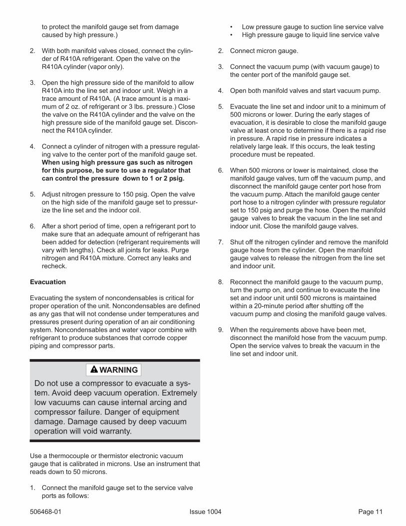
Using an Electronic Leak Detector
1. Connect the high pressure hose of the manifoldgauge set to the suction valve service port. (Normallythe high pressure hose is connected to the liquid lineport; however, connecting it to the suction ports helps
Fire, Explosion, and Personal Safety Hazard.
Failure to follow this warning could result indamage, personal injury, or death.
Never use oxygen to pressurize or purgerefrigeration lines. Oxygen, when exposed toa spark or open flame, can cause damage byfire and/or an explosion, that could result inpersonal injury or death.
WARNING
506468-01 Issue 1004 Page 11
to protect the manifold gauge set from damagecaused by high pressure.)
2. With both manifold valves closed, connect the cylin-der of R410A refrigerant. Open the valve on theR410A cylinder (vapor only).
3. Open the high pressure side of the manifold to allowR410A into the line set and indoor unit. Weigh in atrace amount of R410A. (A trace amount is a maxi-mum of 2 oz. of refrigerant or 3 lbs. pressure.) Closethe valve on the R410A cylinder and the valve on thehigh pressure side of the manifold gauge set. Discon-nect the R410A cylinder.
4. Connect a cylinder of nitrogen with a pressure regulat-ing valve to the center port of the manifold gauge set.When using high pressure gas such as nitrogenfor this purpose, be sure to use a regulator thatcan control the pressure down to 1 or 2 psig.
5. Adjust nitrogen pressure to 150 psig. Open the valveon the high side of the manifold gauge set to pressur-ize the line set and the indoor coil.
6. After a short period of time, open a refrigerant port tomake sure that an adequate amount of refrigerant hasbeen added for detection (refrigerant requirements willvary with lengths). Check all joints for leaks. Purgenitrogen and R410A mixture. Correct any leaks andrecheck.
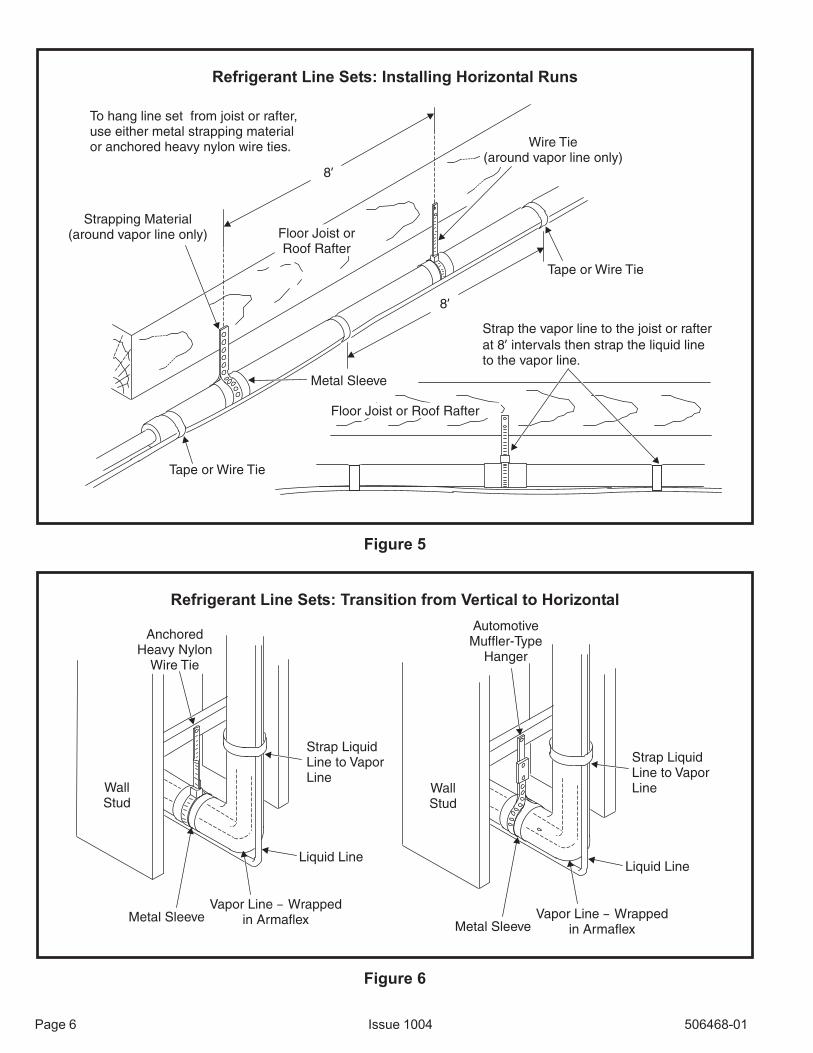
Evacuation
Evacuating the system of noncondensables is critical forproper operation of the unit. Noncondensables are definedas any gas that will not condense under temperatures andpressures present during operation of an air conditioningsystem. Noncondensables and water vapor combine withrefrigerant to produce substances that corrode copperpiping and compressor parts.
• Low pressure gauge to suction line service valve• High pressure gauge to liquid line service valve
2. Connect micron gauge.
3. Connect the vacuum pump (with vacuum gauge) tothe center port of the manifold gauge set.
4. Open both manifold valves and start vacuum pump.
5. Evacuate the line set and indoor unit to a minimum of500 microns or lower. During the early stages ofevacuation, it is desirable to close the manifold gaugevalve at least once to determine if there is a rapid risein pressure. A rapid rise in pressure indicates arelatively large leak. If this occurs, the leak testingprocedure must be repeated.
6. When 500 microns or lower is maintained, close themanifold gauge valves, turn off the vacuum pump, anddisconnect the manifold gauge center port hose fromthe vacuum pump. Attach the manifold gauge centerport hose to a nitrogen cylinder with pressure regulatorset to 150 psig and purge the hose. Open the manifoldgauge valves to break the vacuum in the line set andindoor unit. Close the manifold gauge valves.
7. Shut off the nitrogen cylinder and remove the manifoldgauge hose from the cylinder. Open the manifoldgauge valves to release the nitrogen from the line setand indoor unit.
8. Reconnect the manifold gauge to the vacuum pump,turn the pump on, and continue to evacuate the lineset and indoor unit until 500 microns is maintainedwithin a 20-minute period after shutting off thevacuum pump and closing the manifold gauge valves.
9. When the requirements above have been met,disconnect the manifold hose from the vacuum pump.Open the service valves to break the vacuum in theline set and indoor unit.
Do not use a compressor to evacuate a sys-tem. Avoid deep vacuum operation. Extremelylow vacuums can cause internal arcing andcompressor failure. Danger of equipmentdamage. Damage caused by deep vacuumoperation will void warranty.
WARNING
Use a thermocouple or thermistor electronic vacuumgauge that is calibrated in microns. Use an instrument thatreads down to 50 microns.
1. Connect the manifold gauge set to the service valveports as follows:
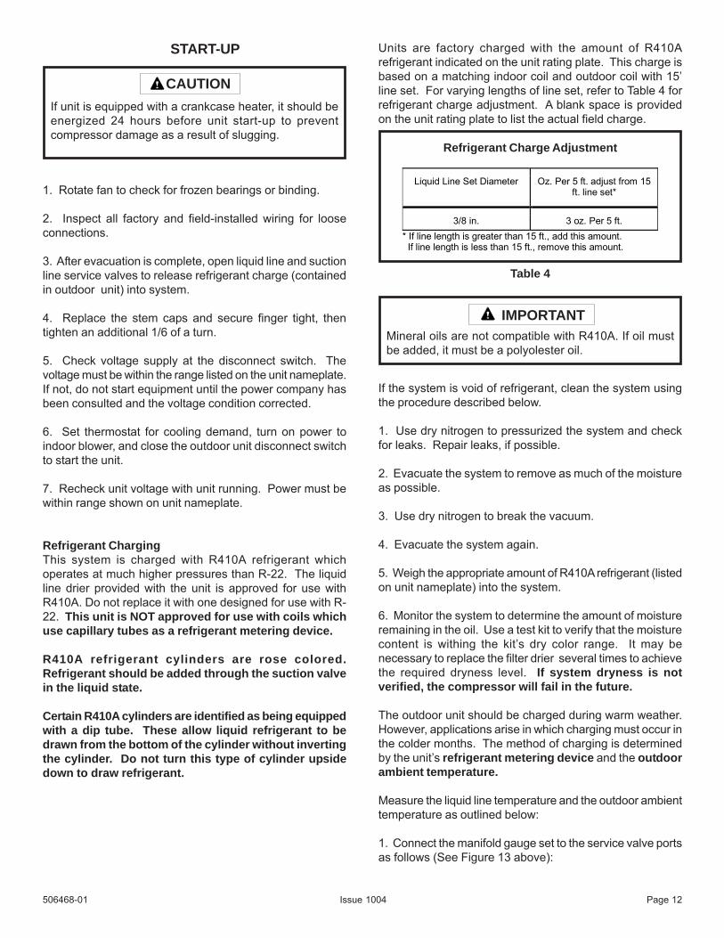
START-UP
1. Rotate fan to check for frozen bearings or binding.
2. Inspect all factory and field-installed wiring for looseconnections.
3. After evacuation is complete, open liquid line and suctionline service valves to release refrigerant charge (containedin outdoor unit) into system.
4. Replace the stem caps and secure finger tight, thentighten an additional 1/6 of a turn.
5. Check voltage supply at the disconnect switch. Thevoltage must be within the range listed on the unit nameplate.If not, do not start equipment until the power company hasbeen consulted and the voltage condition corrected.
6. Set thermostat for cooling demand, turn on power toindoor blower, and close the outdoor unit disconnect switchto start the unit.
7. Recheck unit voltage with unit running. Power must bewithin range shown on unit nameplate.
Refrigerant ChargingThis system is charged with R410A refrigerant whichoperates at much higher pressures than R-22. The liquidline drier provided with the unit is approved for use withR410A. Do not replace it with one designed for use with R-22. This unit is NOT approved for use with coils whichuse capillary tubes as a refrigerant metering device.
R410A refrigerant cylinders are rose colored.Refrigerant should be added through the suction valvein the liquid state.
Certain R410A cylinders are identified as being equippedwith a dip tube. These allow liquid refrigerant to bedrawn from the bottom of the cylinder without invertingthe cylinder. Do not turn this type of cylinder upsidedown to draw refrigerant.
Units are factory charged with the amount of R410Arefrigerant indicated on the unit rating plate. This charge isbased on a matching indoor coil and outdoor coil with 15’line set. For varying lengths of line set, refer to Table 4 forrefrigerant charge adjustment. A blank space is providedon the unit rating plate to list the actual field charge.
If the system is void of refrigerant, clean the system usingthe procedure described below.
1. Use dry nitrogen to pressurized the system and checkfor leaks. Repair leaks, if possible.
2. Evacuate the system to remove as much of the moistureas possible.
3. Use dry nitrogen to break the vacuum.
4. Evacuate the system again.
5. Weigh the appropriate amount of R410A refrigerant (listedon unit nameplate) into the system.
6. Monitor the system to determine the amount of moistureremaining in the oil. Use a test kit to verify that the moisturecontent is withing the kit’s dry color range. It may benecessary to replace the filter drier several times to achievethe required dryness level. If system dryness is notverified, the compressor will fail in the future.
The outdoor unit should be charged during warm weather.However, applications arise in which charging must occur inthe colder months. The method of charging is determinedby the unit’s refrigerant metering device and the outdoorambient temperature.
Measure the liquid line temperature and the outdoor ambienttemperature as outlined below:
1. Connect the manifold gauge set to the service valve portsas follows (See Figure 13 above):
If unit is equipped with a crankcase heater, it should beenergized 24 hours before unit start-up to preventcompressor damage as a result of slugging.
CAUTION
Mineral oils are not compatible with R410A. If oil mustbe added, it must be a polyolester oil.
IMPORTANT
Table 4
Liquid Line Set Diameter
Oz. Per 5 ft. adjust from 15 ft. line set*
3/8 in. 3 oz. Per 5 ft. * If line length is greater than 15 ft., add this amount. If line length is less than 15 ft., remove this amount.
Refrigerant Charge Adjustment
506468-01 Page 12Issue 1004
506468-01 Issue 1004 Page 13
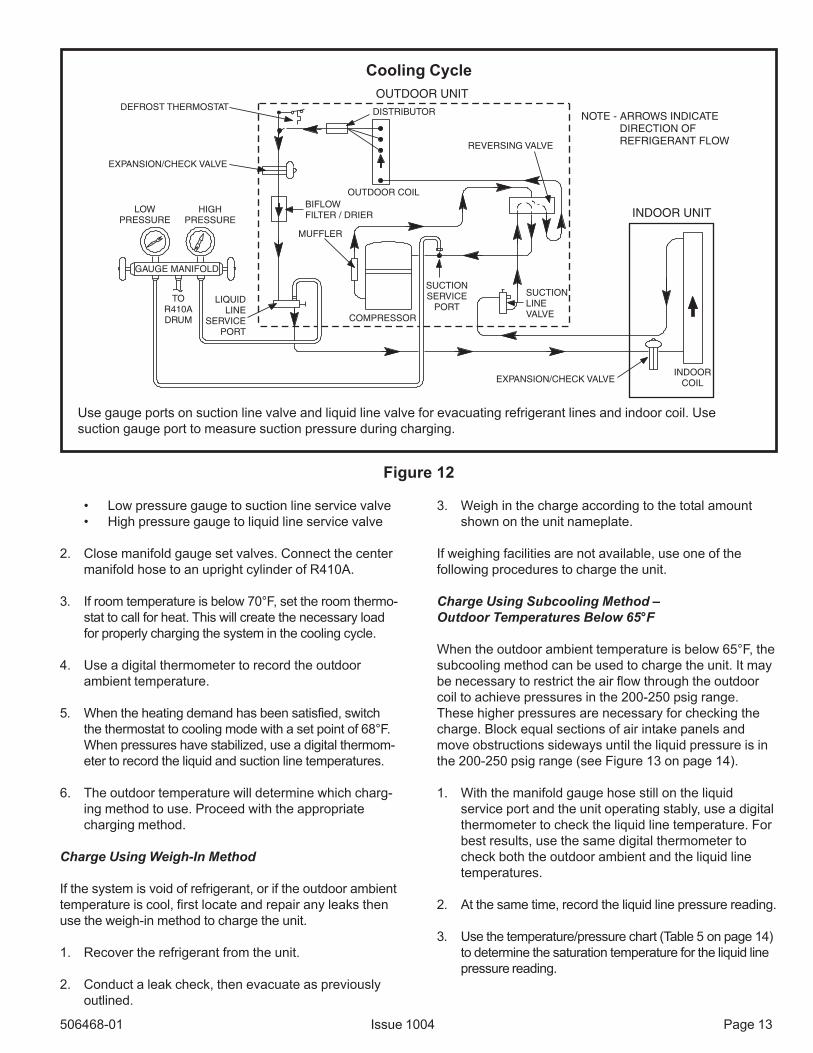
Cooling Cycle
Use gauge ports on suction line valve and liquid line valve for evacuating refrigerant lines and indoor coil. Usesuction gauge port to measure suction pressure during charging.
Figure 12
OUTDOOR COIL
DEFROST THERMOSTAT
EXPANSION/CHECK VALVE
BIFLOWFILTER / DRIER
TOR410ADRUM
LOWPRESSURE
HIGHPRESSURE
COMPRESSOR
REVERSING VALVE
SUCTIONLINEVALVE
MUFFLER
NOTE - ARROWS INDICATEDIRECTION OFREFRIGERANT FLOW
SUCTIONSERVICE
PORT
EXPANSION/CHECK VALVE
INDOOR UNIT
OUTDOOR UNIT
LIQUIDLINE
SERVICEPORT
GAUGE MANIFOLD
DISTRIBUTOR
INDOORCOIL
• Low pressure gauge to suction line service valve• High pressure gauge to liquid line service valve
2. Close manifold gauge set valves. Connect the centermanifold hose to an upright cylinder of R410A.
3. If room temperature is below 70°F, set the room thermo-stat to call for heat. This will create the necessary loadfor properly charging the system in the cooling cycle.
4. Use a digital thermometer to record the outdoorambient temperature.
5. When the heating demand has been satisfied, switchthe thermostat to cooling mode with a set point of 68°F.When pressures have stabilized, use a digital thermom-eter to record the liquid and suction line temperatures.
6. The outdoor temperature will determine which charg-ing method to use. Proceed with the appropriatecharging method.
Charge Using Weigh-In Method
If the system is void of refrigerant, or if the outdoor ambienttemperature is cool, first locate and repair any leaks thenuse the weigh-in method to charge the unit.
1. Recover the refrigerant from the unit.
2. Conduct a leak check, then evacuate as previouslyoutlined.
3. Weigh in the charge according to the total amountshown on the unit nameplate.
If weighing facilities are not available, use one of thefollowing procedures to charge the unit.
Charge Using Subcooling Method –Outdoor Temperatures Below 65°F
When the outdoor ambient temperature is below 65°F, thesubcooling method can be used to charge the unit. It maybe necessary to restrict the air flow through the outdoorcoil to achieve pressures in the 200-250 psig range.These higher pressures are necessary for checking thecharge. Block equal sections of air intake panels andmove obstructions sideways until the liquid pressure is inthe 200-250 psig range (see Figure 13 on page 14).
1. With the manifold gauge hose still on the liquidservice port and the unit operating stably, use a digitalthermometer to check the liquid line temperature. Forbest results, use the same digital thermometer tocheck both the outdoor ambient and the liquid linetemperatures.
2. At the same time, record the liquid line pressure reading.
3. Use the temperature/pressure chart (Table 5 on page 14)to determine the saturation temperature for the liquid linepressure reading.

5. Compare the subcooling value with those shown in Table6. If subcooling is greater than shown, recover somerefrigerant. If subcooling is less than shown, add somerefrigerant.
506468-01 Page 14
Table 5
R410A Temperature/Pressure ChartTemp. EF
Pressure Psig
Temp. EF
Pressure Psig
Temp. EF
Pressure Psig
32 100.8 74 214.0 116 396.0
33 102.9 75 217.4 117 401.3
34 105.0 76 220.9 118 406.7
35 107.1 77 224.4 119 412.2
36 109.2 78 228.0 120 417.7
37 111.4 79 231.6 121 423.2
38 113.6 80 235.3 122 428.8
39 115.8 81 239.0 123 434.5
40 118.0 82 242.7 124 440.2
41 120.3 83 246.5 125 445.9
42 122.6 84 250.3 126 451.8
43 125.0 85 254.1 127 457.6
44 127.3 86 258.0 128 463.5
45 129.7 87 262.0 129 469.5
46 132.2 88 266.0 130 475.6
47 134.6 89 270.0 131 481.6
48 137.1 90 274.1 132 487.8
49 139.6 91 278.2 133 494.0
50 142.2 92 282.3 134 500.2
51 144.8 93 286.5 135 506.5
52 147.4 94 290.3 136 512.9
53 150.1 95 295.1 137 519.3
54 152.8 96 299.4 138 525.8
55 155.5 97 303.8 139 532.4
56 158.2 98 308.2 140 539.0
57 161.0 99 312.7 141 545.6
58 163.9 100 317.2 142 552.3
59 166.7 101 321.8 143 559.1
60 169.6 102 326.4 144 565.9
61 172.6 103 331.0 145 572.8
62 175.5 104 335.7 146 579.8
63 178.5 105 340.5 147 586.8
64 181.6 106 345.3 148 593.8
65 184.3 107 350.1 149 601.0
66 187.7 108 355.0 150 608.1
67 190.9 109 360.0 151 615.4
68 194.1 110 365.0 152 622.7
69 197.3 111 370.0 153 630.1
70 200.6 112 375.1 154 637.5
71 203.9 113 380.2 155 645.0
72 207.2 114 385.4
73 210.6 115 390.7
72 207.2 114 385.4
73 210.6
115 390.7
Charge Using Approach Method (TXV System) - OutdoorTemperatures 65°F or Above
The following procedure is intended as a general guide andis for use on expansion valve systems only. For best results,indoor temperature should be 70°F to 80°F. Monitor systempressures while charging.
1. Record outdoor ambient temperature usig a digitalthermometer.
2. Attach high pressure gauge set and operate unit forseveral minutes to allow system pressures to stabilize.
3. Compare stabilized pressures with those provided in Table7. Minor variations in these pressures may be expected
=
_Saturation Temperature °F
Liquid Line Temperature °F
Subcooling Value °F
°
°
°
4. Subtract the liquid line temperature from the saturationtemperature (according to the chart) to determineSubcooling.
Blocking Outdoor Coil
CARDBOARD OR
PLASTIC SHEET
Outdoor coil should beblocked one side at a timewith cardboard or plasticsheet until proper testingpressures are reached.
Figure 13
Issue 1004
Table 6
Subcooling Values

506468-01 Page 15Issue 1004
Table 7
due to differences in installations. Significantdifferences could mean that the system is notproperly charged or that a problem exists with somecomponent in the system. Pressures higher than thoselisted indicate that the system is overcharged. Pressureslower than those listed indicate that the
system is undercharged. Verify adjusted charge using theapproach method.
4. Use the same digital thermometer to check liquid linetemperature.
Normal Operating PressuresHeating & Cooling
Cooling Indoor: 80 db; 67 wbHeating (indoor): 70°F± 2 psi
L - Liquid S- Suction
Values provided above are for HSV match pressures; different indoor unit match, and indoor load will causepressures to vary.

5. Subtract the outdoor ambient temperature from the liquidline temperture to determine the approach temperature.
506468-01 Page 16
Check Charge Using Normal Operating Pressures
Use Table 7 to perform maintenance checks. Table 7 is nota procedure for charging the system. Minor variations inthese pressures may be due to differences in installations.Significant deviations could mean that the system is notproperly charged or that a problem exists with somecomponent in the system.
Issue 1004
6. Compare the approach value with those shown in Table8. If the values do not agree with those provided in Table 8,add refrigerant to lower the approach temperature or recoverrefrigerant from the system to increase the approachtemperature.
=
_Outdoor Ambient Temperature °F
Liquid Line Temperature °F
Approach Temperature °F
°
°
°
Table 8
Approach Values for TXV Systems
Approach value is the liquid line temperature minus the outdoorambient temperature (±1°F).
Note: For best results, use the same digital thermometer to checkboth outdoor ambient and liquid temperatures.

OPERATION
Outdoor unit and indoor blower cycle on demand from theroom thermostat. When the thermostat blower switch ismoved to the ON position, the indoor blower operatescontinuously.
Filter DrierThe unit is equipped with a large capacity bi-flow filterwhich keeps the system clean and dry. If replacement isnecessary, replace with one of similar design andcapacity. The replacement filter drier must be suitable foruse with R410A refrigerant.
Crankcase HeaterIf unit is equipped with a crankcase heater, it shouldbe energized 24 hours before unit start-up to preventcompressor damage as a result of slugging.
Emergency Heat Function (Room Thermostat)An emergency heat function is designed into some roomthermostats. This feature is applicable when isolation ofoutdoor unit is required or when auxiliary electric heat isstage by outdoor thermostats. When the room thermostatis placed in the emergency heat position, the outdoor unitcontrol circuit is isolated from power and the field-suppliedrelays bypass the outdoor thermostats. An amberindicating light simultaneously comes on to remind thehomeowner that the unit is operating in the emergencyheat mode.
Emergency heat is usually used during an outdoorshutdown, but it should also be used following a poweroutage if power has been off for over an hour and theoutdoor temperature is below 50°F. System should be leftin the emergency heat mode at least 6 hours to allow thecrankcase heater sufficient time to prevent compressorslugging.
506468-01 Page 17
DEMAND DEFROST SYSTEM DESCRIPTIONThe demand defrost controller measures differential
temperatures to detect when the system is performingpoorly because of ice build-up on the outdoor coil. Thecontroller “self-calibrates” when the defrost system startsand after each system defrost cycle. The defrost controlboard components are shown below.
The control monitors ambient temperature, outdoorcoil temperature, and total run time to determine when adefrost cycle is required. The coil temperature probe isdesigned with a spring clip to allow mounting to theoutside coil tubing. The location of the coil sensor isimportant for proper defrost operation.
Issue 1004
NOTE - The demand defrost board accuratelymeasures the performance of the system as frostaccumulates on the outdoor coil. This typically willtranslate into longer running time between defrostcycles as more frost accumulates on the outdoor coilbefore the board initiates defrost cycles.
DIAGNOSTIC LEDSThe state (Off, On, Flashing) of two LEDs on the defrostboard (DS1 [Red] and DS2 [Green]) indicate diagnosticsconditions that are described in table.
Mode Green Led (DS2) Red Led (DS1)
OFFOFFNo power to control
Normal operation/
power to control
Anti-short cycle
lockout
Simultaneous Slow Flash
Alternating Slow Flash
Low pressure switch
fault (Optional)
Low pressure switch
lockout (Optional)
High presssure switch
fault (Optional)
High pressure switch
lockout (Optional)
OFF
OFF
OFF OFF
OFF
ON
Slow FLASH
Slow FLASH

DEFROST BOARD PRESSURE SWITCHCONNECTIONSThe unit’s automatic reset pressure switches (LO PS -S87 and HI PS - S4) are factory-wired into the defrostboard on the LO-PS and HI-PS terminals, respectively.
(OPTIONAL) Low Pressure Switch (LO-PS) — Whenthe low pressure switch trips, the defrost board will cycleoff the compressor, and the strike counter in the boardwill count one strike. The low pressure switch is ignoredunder the following conditions:! during the defrost cycle and 90 seconds after the
termination of defrost! when the average ambient sensor temperature is below
15° F (-9°C)! for 90 seconds following the start up of the compressor! during “test” mode
High Pressure Switch (HI-PS) — When the highpressure switch trips, the defrost board will cycle off thecompressor, and the strike counter in the board will countone strike.
DEFROST BOARD PRESSURE SWITCH SETTINGSHigh Pressure (auto reset) - trip at 590 psig; reset at418.Low Pressure (auto reset) - trip at 25 psig; reset at 40.
5-STRIKE LOCKOUT FEATUREThe internal control logic of the board counts the pressureswitch trips only while the Y1 (Input) line is active. If apressure switch opens and closes four times during a Y1(Input), the control logic will reset the pressure switch tripcounter to zero at the end of the Y1 (Input). If thepressure switch opens for a fifth time during the currentY1 (Input), the control will enter a lockout condition.
The 5-strike pressure switch lockout condition can bereset by cycling OFF the 24-volt power to the controlboard or by shorting the TEST pins between 1 and 2seconds. All timer functions (run times) will also be reset.
If a pressure switch opens while the Y1 Out line isengaged, a 5-minute short cycle will occur after the switchcloses.
DEFROST SYSTEM SENSORSSensors connect to the defrost board through a field–replaceable harness assembly that plugs into the board.Through the sensors, the board detects outdoor ambient,coil, and discharge temperature fault conditions. As thedetected temperature changes, the resistance across thesensor changes. Sensor resistance values can bechecked by ohming across pins .
NOTE - When checking the ohms across a sensor, beaware that a sensor showing a resistance value thatis not within the range shown, may be performing asdesigned. However, if a shorted or open circuit isdetected, then the sensor may be faulty and thesensor harness will needs to be replaced.
Coil Sensor—The coil temperature sensor considersoutdoor temperatures below -35°F (-37°C) or above120°F (48°C) as a fault. If the coil temperature sensor isdetected as being open, shorted or out of the temperaturerange of the sensor, the board will not perform demand ortime/temperature defrost operation and will display theappropriate fault code. Heating and cooling operation willbe allowed in this fault condition.
SensorTemperature
Range °F (°C) Red Led (DS1)
Outdoor
(Ambient)
Coil
Discharge (If
applicable)
Note: Sensor resistance decreases as sensed temperature increases.
Pins/Wire
Color
-35 (-37 to 120
(48)280,000 to 3750
3 & 4
(Black)
-35 (-37) to 120
(48)280,000 to 3750
24 (-4) to 350
(176)41,000 to 103
5 & 6
(Brown)
1 & 2
(Yellow)
Sensor Temp. / Resistance Range
Ambient Sensor—The ambient sensor considersoutdoor temperatures below -35°F (-37°C) or above120°F (48°C) as a fault. If the ambient sensor is detectedas being open, shorted or out of the temperature range ofthe sensor, the board will not perform demand defrostoperation. The board will revert to time/temperaturedefrost operation and will display the appropriate faultcode. Heating and cooling operation will be allowed in thisfault condition.
NOTE - Within a single room thermostatdemand, if 5-strikes occur, the board will lockoutthe unit. Defrost board 24 volt power “R” mustbe cycled “OFF” or the “TEST” pins on boardmust be shorted between 1 to 2 seconds to resetthe board.
506468-01 Page 18Issue 1004

Defrost Temperature Termination Shunt (Jumper)Pins—The defrost board selections are: 50, 70, 90, and100°F (10, 21, 32 and 38°C). The shunt termination pin isfactory set at 50°F (10°C). If the temperature shunt is notinstalled, the default termination temperature is 90°F(32°C).
DELAY MODEThe defrost board has a field-selectable function toreduce occasional sounds that may occur while the unit iscycling in and out of the defrost mode. When a jumper isinstalled on the DELAY pins, the compressor will becycled off for 30 seconds going in and out of the defrostmode. Units are shipped with jumper installed on DELAYpins.
NOTE - The 30 second off cycle is NOT functionalwhen jumpering the TEST pins.
OPERATIONAL DESCRIPTIONThe defrost control board has three basic operationalmodes: normal, calibration, and defrost.
Normal Mode—The demand defrost board monitors theO line, to determine the system operating mode (heat/cool), outdoor ambient temperature, coil temperature(outdoor coil) and compressor run time to determinewhen a defrost cycle is required.
Calibration Mode—The board is considered uncalibratedwhen power is applied to the board, after cool modeoperation, or if the coil temperature exceeds thetermination temperature when it is in heat mode.
Calibration of the board occurs after a defrost cycle toensure that there is no ice on the coil. During calibration,the temperature of both the coil and the ambient sensorare measured to establish the temperature differentialwhich is required to allow a defrost cycle.
Defrost Mode—The following paragraphs provide adetailed description of the defrost system operation.
DETAILED DEFROST SYSTEM OPERATIONDefrost Cycles—The demand defrost control boardinitiates a defrost cycle based on either frost detection ortime.! Frost Detection—If the compressor runs longer than
30 minutes and the actual difference between theclear coil and frosted coil temperatures exceeds themaximum difference allowed by the control, a defrostcycle will be initiated.IMPORTANT - The demand defrost control boardwill allow a greater accumulation of frost and willinitiate fewer defrost cycles than a time/temperature defrost system.
! Time—If 6 hours of heating mode compressor runtime has elapsed since the last defrost cycle while thecoil temperature remains below 35°F (2°C), thedemand defrost control will initiate a defrost cycle.
Actuation—When the reversing valve is de-energized,the Y1 circuit is energized, and the coil temperature isbelow 35°F (2°C), the board logs the compressor runtime. If the board is not calibrated, a defrost cycle will beinitiated after 30 minutes of heating mode compressor runtime. The control will attempt to self-calibrate after this(and all other) defrost cycle(s).
Calibration success depends on stable systemtemperatures during the 20-minute calibration period. Ifthe board fails to calibrate, another defrost cycle will beinitiated after 45 minutes of heating mode compressor runtime. Once the defrost board is calibrated, it initiates ademand def rost cycle when the difference between theclear coil and frosted coil temperatures exceeds themaximum difference allowed by the control OR after 6hours of heating mode compressor run time has beenlogged since the last defrost cycle.
NOTE - If ambient or coil fault is detected, the boardwill not execute the “TEST” mode.
Termination—The defrost cycle ends when the coiltemperature exceeds the termination temperature or after14 minutes of defrost operation. If the defrost isterminated by the 14-minute timer, another defrost cyclewill be initiated after 30 minutes of run time.
Test Mode—When Y1 is energized and 24V power isbeing applied to the board, a test cycle can be initiated byplacing the termination temperature jumper across the“Test” pins for 2 to 5 seconds. If the jumper remainsacross the “Test” pins longer than 5 seconds, the controlwill ignore the test pins and revert to normal operation.The jumper will initiate one cycle per test.
Enter the “TEST” mode by placing a shunt (jumper)across the “TEST” pins on the board after power-up.(The “TEST” pins are ignored and the test function islocked out if the shunt is applied on the “TEST” pinsbefore power-up). Board timings are reduced, the low-pressure switch is ignored and the board will clear anyactive lockout condition.
Each test pin shorting will result in one test event.For each “TEST” the shunt (jumper) must be removed forat least 1 second and reapplied. Refer to flow chart for“TEST” operation.
Note: The Y1 input must be active (ON) and the “O”room thermostat terminal into board must beinactive.
DEFROST BOARD DIAGNOSTICSSee defrost control board diagnostic LED table on nextpage to determine defrost board operational conditionsand to diagnose cause and solution to problems.
506468-01 Page 19Issue 1004

506468-01 Page 20Issue 1004

506468-01 Page 21Issue 1004
Defrost Control Board Diagnostic LEDs

506468-01 Issue 1004 Page 22
System Diagnostic Module
4HP16LT units contain a diagnostic module for trouble-shooting heat pump system failures. By monitoring andanalyzing data from the compressor and thermostatdemand, the module can accurately detect the cause ofelectrical and system related failure without any sensors.If a system problem occurs, a flashing LED indicatorcommunicates the failure code.
LED Description
POWER LED (Green) indicates voltage is present at thepower connection of the module.
ALERT LED (Yellow) communicates an abnormal systemcondition through a unique flash code. The ALERT LEDwill flash a number of times consecutively, pause, andthen repeat the process. The number of consecutive
Flash Codes
Table 10
flashes correlates to a particular abnormal condition.TRIP LED (Red) indicates there is a demand signal fromthe thermostat but no current to the compressor is de-tected by the module. The TRIP LED typically indicatesthe compressor protector is open or may indicate missingsupply power to the compressor.
Interpreting the Diagnostic LEDs
When an abnormal system condition occurs, the diagnos-tic module displays the appropriate ALERT and/or TRIPLED. The yellow ALERT LED will flash a number of timesconsecutively, pause, and then repeat the process. Toidentify a flash code number, count the number of con-secutive flashes. Refer to Table 10 below and Table 11 onpage 20 for information on the flash codes.
Every time the module powers up, the last ALERT LEDflash code that occurred prior to shutdown is displayed for
DELsutatS
noitpircseDtluaF noitamrofnIgnitoohselbuorT
REWOP)neerG(
rewopsaheludoM slanimreteludomtatneserpsiegatlovylppuS
PIRT)deR(
dnamedtatsomrehT,tneserpsi1Ylangis
rosserpmocehttubgninnurtonsi
neposirotcetorprosserpmoC.1erusserpdaehhgihrofkcehC*
egatlovylppusrosserpmockcehC*nepositcennocsidrewoptinuroodtuO.2
neposi)s(esufrorekaerbtiucricrosserpmoC.3tcatnocgnikamtonsirotcennocroeriwnekorB.4
metsysnitneserpfinepohctiwserusserpwoL.5nepodeliafsahrotcatnocrosserpmoC.6
TRELA)wolleY(
hsalF1edoC
miTnuRgnoL eeeeesirosserpmoC
gninnurnurgnolylemertxe
selcyc
noelbacilppatoN()sledompmuptaeh
--
TRELA)wolleY(
hsalF2edoC
metsySpirTerusserP
noitcusroegrahcsiDerusserp
rostimilfotuorosserpmoc
dedaolrevo
erusserpdaehhgiH.1metsysnitneserpfihctiwserusserphgihkcehC*tnaregirferhtiwdegrahcrevosimetsysfikcehC*
metsysnielbasnednoc-nonrofkcehC*)degamad,dekcolb,ytrid(noitalucricriaroopliocresnednoC.2
gninnurtonsinafresnednoC.3roticapacnafkcehC*
srotcennocdnagniriwnafkcehC*egakcolbroeruliafrofrotomnafkcehC*
egakaellaitnatsbussahtcudrianruteR.4ofni1edoChsalFkcehc,metsysnitneserphctiwserusserpwolfI.5

Page 23 Issue 1004 506468-01
Flash Codes (cont.)
DELsutatS
noitpircseDtluaF noitamrofnIgnitoohselbuorT
TRELA)wolleY(
hsalF3edoC
gnilcyCtrohSsirosserpmoC
gninnurylfeirbylno
tnettimretnisilangisdnamedtatsomrehT.1evitcefeddraoblortnocroyaleryaledemiT.2
ofni2edoChsalFotog,tneserphctiwserusserphgihfI.3ofni1edoChsalFotog,tneserphctiwserusserpwolfI.4
TRELA)wolleY(
hsalF4edoC
rotoRdekcoL
deliafsahroticapacnuR.1)wolsitcennocsidtaegatlovfiytilitutcatnoc(egatlovenilwoL.2
snoitcennocgniriwkcehC*rosserpmocnitnaregirferdiuqilevissecxE.3
dezieserasgniraebrosserpmoC.4levelliorosserpmocerusaeM*
TRELA)wolleY(
hsalF5edoC
tiucriCnepO
nepositcennocsidrewoptinuroodtuO.1neposi)s(esufrorekaerbtiucricrosserpmoC.2
nepodeliafsahrotcatnocrosserpmoC.3srotcennocdnagniriwrotcatnocrosserpmockcehC*
)neporo,dettip,denrub(eruliafrotcatnocrosserpmocrofkcehC*rosserpmocdnaylppusneewtebsrotcennocdnagniriwkcehC*
liocrotcatnocrosserpmoctaegatlovtolipwolrofkcehC*teserlaunamseriuqerdnaneposihctiwserusserphgiH.4snoitcennocrogniriwylppusrosserpmocnitiucricnepO.5
erutarepmettneibmaemertxeoteudemitteserrotcetorprosserpmocgnolyllausunU.6degamaderasgnidniwrosserpmoC.7
ecnatsisergnidniwrotomrosserpmockcehC*
TRELA)wolleY(
hsalF6edoC
tiucriCtratSnepOnurniylnotnerruC
tiucric
deliafsahroticapacnuR.1snoitcennocrogniriwtratsrosserpmocnitiucricnepO.2
lanimretSrosserpmocehtdnaylppusneewtebsrotcennocdnagniriwkcehC*degamadsignidniwtratsrosserpmoC.3
ecnatsisergnidniwrotomrosserpmockcehC*
TRELA)wolleY(
hsalF7edoC
tiucriCnuRnepOtratsniylnotnerruC
tiucric
snoitcennocrogniriwnurrosserpmocnitiucricnepO.1lanimretRrosserpmocehtdnaylppusneewtebsrotcennocdnagniriwkcehC*
degamadsignidniwnurrosserpmoC.2ecnatsisergnidniwrotomrosserpmockcehC*
TRELA)wolleY(
hsalF8edoC
rotcatnoCdedleWsyawlarosserpmoC
snur
desolcdeliafsahrotcatnocrosserpmoC.1eludomotdetcennoctonlangisdnamedtatsomrehT.2
TRELA)wolleY(
hsalF9edoC
egatloVwoLsseltiucriclortnoC
CAV71naht
dedaolrevosiremrofsnarttiucriclortnoC.1)wolsitcennocsidtaegatlovfiytilitutcatnoc(egatlovenilwoL.2
snoitidnocgniriwkcehC*
Table 11
60 seconds. The module will continue to display theprevious flash code until the condition returns to normal or24VAC is removed from the module. TRIP and ALERTLEDs flashing at the same time means control circuitvoltage is too low for operation.
24VAC Power Wiring
The diagnostic module requires a constant nominal24VAC power supply. The wiring to the module’s R and Cterminals must be directly from the indoor unit or thermo-stat. The module cannot be powered by R and C terminalson the defrost board without experiencing nuisance alerts.
506468-01 Issue 1004 Page 24
Table 12
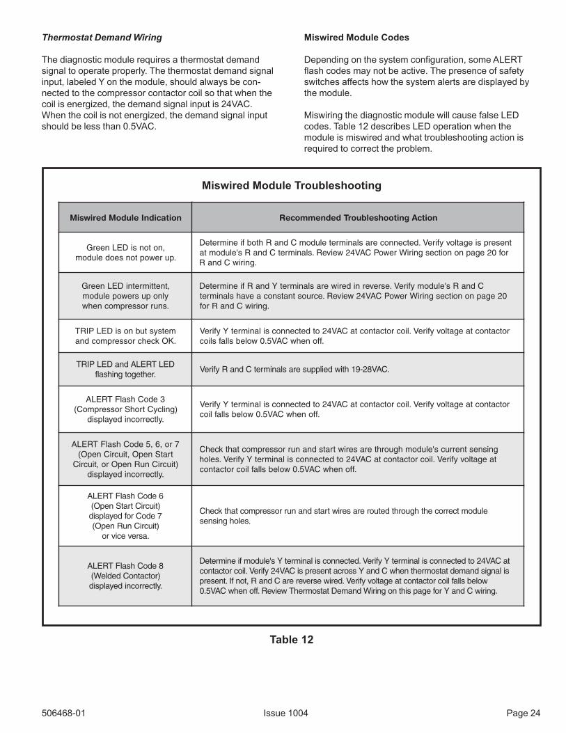
Miswired Module Troubleshooting
Thermostat Demand Wiring
The diagnostic module requires a thermostat demandsignal to operate properly. The thermostat demand signalinput, labeled Y on the module, should always be con-nected to the compressor contactor coil so that when thecoil is energized, the demand signal input is 24VAC.When the coil is not energized, the demand signal inputshould be less than 0.5VAC.
Miswired Module Codes
Depending on the system configuration, some ALERTflash codes may not be active. The presence of safetyswitches affects how the system alerts are displayed bythe module.
Miswiring the diagnostic module will cause false LEDcodes. Table 12 describes LED operation when themodule is miswired and what troubleshooting action isrequired to correct the problem.
noitacidnIeludoMderiwsiM noitcAgnitoohselbuorTdednemmoceR
,notonsiDELneerG.purewoptonseodeludom
tneserpsiegatlovyfireV.detcennoceraslanimreteludomCdnaRhtobfienimreteDrof02egapnonoitcesgniriWrewoPCAV42weiveR.slanimretCdnaRs'eludomta
.gniriwCdnaR
,tnettimretniDELneerGylnopusrewopeludom.snurrosserpmocnehw
CdnaRs'eludomyfireV.esrevernideriweraslanimretYdnaRfienimreteD02egapnonoitcesgniriWrewoPCAV42weiveR.ecruostnatsnocaevahslanimret
.gniriwCdnaRrof
metsystubnosiDELPIRT.KOkcehcrosserpmocdna
rotcatnoctaegatlovyfireV.liocrotcatnoctaCAV42otdetcennocsilanimretYyfireV.ffonehwCAV5.0wolebsllafslioc
DELTRELAdnaDELPIRT.rehtegotgnihsalf
.CAV82-91htiwdeilppuseraslanimretCdnaRyfireV
3edoChsalFTRELA)gnilcyCtrohSrosserpmoC(
.yltcerrocnideyalpsid
rotcatnoctaegatlovyfireV.liocrotcatnoctaCAV42otdetcennocsilanimretYyfireV.ffonehwCAV5.0wolebsllaflioc
7ro,6,5edoChsalFTRELAtratSnepO,tiucriCnepO(
)tiucriCnuRnepOro,tiucriC.yltcerrocnideyalpsid
gnisnestnerrucs'eludomhguorhteraseriwtratsdnanurrosserpmoctahtkcehCtaegatlovyfireV.liocrotcatnoctaCAV42otdetcennocsilanimretYyfireV.seloh
.ffonehwCAV5.0wolebsllafliocrotcatnoc
6edoChsalFTRELA)tiucriCtratSnepO(7edoCrofdeyalpsid)tiucriCnuRnepO(
.asrevecivro
eludomtcerrocehthguorhtdetuoreraseriwtratsdnanurrosserpmoctahtkcehC.selohgnisnes
8edoChsalFTRELA)rotcatnoCdedleW(.yltcerrocnideyalpsid
taCAV42otdetcennocsilanimretYyfireV.detcennocsilanimretYs'eludomfienimreteDsilangisdnamedtatsomrehtnehwCdnaYssorcatneserpsiCAV42yfireV.liocrotcatnoc
wolebsllafliocrotcatnoctaegatlovyfireV.deriwesrevereraCdnaR,tonfI.tneserp.gniriwCdnaYrofegapsihtnogniriWdnameDtatsomrehTweiveR.ffonehwCAV5.0

Page 25 Issue 1004 506468-01
MAINTENANCE
Before performing maintenance operations onsystem, turn the electric power to unit OFF atdisconnect switch(es). Unit may have multiplepower supplies. Electrical shock could causepersonal injury or death.
WARNING
Before the start of each heating and cooling season, thefollowing service checks should be performed by aqualified service technician.
• Inspect and clean outdoor and indoor coils. Theoutdoor coil may be flushed with a water hose.
NOTE: It may be necessary to flush the outdoor coilmore frequently if it is exposed to substances whichare corrosive or which block airflow across the coil(such as pet urine, cottonwood seeds, etc...).
• Visually inspect the refrigerant lines and coils for leaks.
• Check wiring for loose connections.
• Check voltage at the indoor and outdoor units (withunits operating).
• Check amperage draw at the outdoor fan motor,compressor, and indoor blower motor. Values shouldbe compared with those given on unit nameplate.
• Check, clean (or replace) indoor unit filters.
• Check the refrigerant charge and gauge the systempressures.
• Check the condensate drain line for free and unob-structed flow. Clean drain line, if necessary.
• Adjust blower speed for cooling. Measure the pressuredrop over the coil to determine the correct blower CFM.
• Belt drive blowers: Check drive belt for wear andproper tensions.
If insufficient cooling is reported, the unit should begauged and refrigerant charge checked (see RefrigerantCharging on page 12).
506468-01 Issue 1004 Page 26
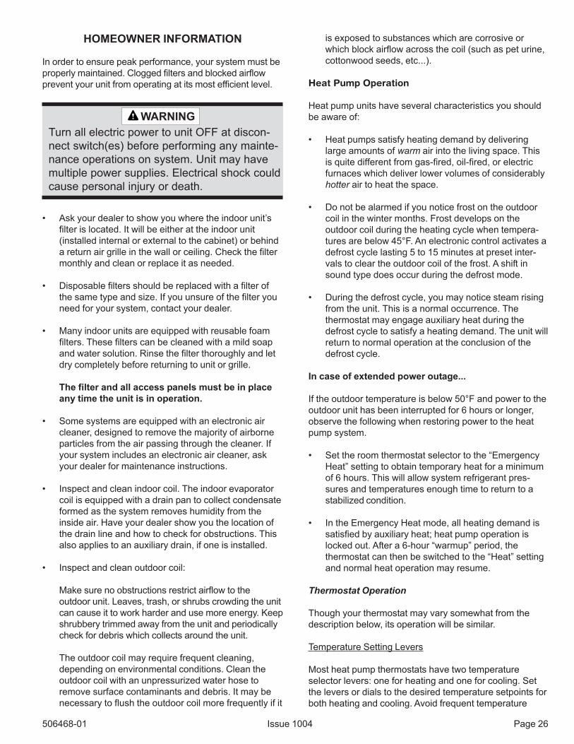
HOMEOWNER INFORMATION
In order to ensure peak performance, your system must beproperly maintained. Clogged filters and blocked airflowprevent your unit from operating at its most efficient level.
Turn all electric power to unit OFF at discon-nect switch(es) before performing any mainte-nance operations on system. Unit may havemultiple power supplies. Electrical shock couldcause personal injury or death.
WARNING
• Ask your dealer to show you where the indoor unit’sfilter is located. It will be either at the indoor unit(installed internal or external to the cabinet) or behinda return air grille in the wall or ceiling. Check the filtermonthly and clean or replace it as needed.
• Disposable filters should be replaced with a filter ofthe same type and size. If you unsure of the filter youneed for your system, contact your dealer.
• Many indoor units are equipped with reusable foamfilters. These filters can be cleaned with a mild soapand water solution. Rinse the filter thoroughly and letdry completely before returning to unit or grille.
The filter and all access panels must be in placeany time the unit is in operation.
• Some systems are equipped with an electronic aircleaner, designed to remove the majority of airborneparticles from the air passing through the cleaner. Ifyour system includes an electronic air cleaner, askyour dealer for maintenance instructions.
• Inspect and clean indoor coil. The indoor evaporatorcoil is equipped with a drain pan to collect condensateformed as the system removes humidity from theinside air. Have your dealer show you the location ofthe drain line and how to check for obstructions. Thisalso applies to an auxiliary drain, if one is installed.
• Inspect and clean outdoor coil:
Make sure no obstructions restrict airflow to theoutdoor unit. Leaves, trash, or shrubs crowding the unitcan cause it to work harder and use more energy. Keepshrubbery trimmed away from the unit and periodicallycheck for debris which collects around the unit.
The outdoor coil may require frequent cleaning,depending on environmental conditions. Clean theoutdoor coil with an unpressurized water hose toremove surface contaminants and debris. It may benecessary to flush the outdoor coil more frequently if it
is exposed to substances which are corrosive orwhich block airflow across the coil (such as pet urine,cottonwood seeds, etc...).
Heat Pump Operation
Heat pump units have several characteristics you shouldbe aware of:
• Heat pumps satisfy heating demand by deliveringlarge amounts of warm air into the living space. Thisis quite different from gas-fired, oil-fired, or electricfurnaces which deliver lower volumes of considerablyhotter air to heat the space.
• Do not be alarmed if you notice frost on the outdoorcoil in the winter months. Frost develops on theoutdoor coil during the heating cycle when tempera-tures are below 45°F. An electronic control activates adefrost cycle lasting 5 to 15 minutes at preset inter-vals to clear the outdoor coil of the frost. A shift insound type does occur during the defrost mode.
• During the defrost cycle, you may notice steam risingfrom the unit. This is a normal occurrence. Thethermostat may engage auxiliary heat during thedefrost cycle to satisfy a heating demand. The unit willreturn to normal operation at the conclusion of thedefrost cycle.
In case of extended power outage...
If the outdoor temperature is below 50°F and power to theoutdoor unit has been interrupted for 6 hours or longer,observe the following when restoring power to the heatpump system.
• Set the room thermostat selector to the “EmergencyHeat” setting to obtain temporary heat for a minimumof 6 hours. This will allow system refrigerant pres-sures and temperatures enough time to return to astabilized condition.
• In the Emergency Heat mode, all heating demand issatisfied by auxiliary heat; heat pump operation islocked out. After a 6-hour “warmup” period, thethermostat can then be switched to the “Heat” settingand normal heat operation may resume.
Thermostat Operation
Though your thermostat may vary somewhat from thedescription below, its operation will be similar.
Temperature Setting Levers
Most heat pump thermostats have two temperatureselector levers: one for heating and one for cooling. Setthe levers or dials to the desired temperature setpoints forboth heating and cooling. Avoid frequent temperature
Page 27 Issue 1004 506468-01
adjustment; turning the unit off and back on beforepressures equalize puts stress on unit compressor.
Fan Switch
In AUTO or INT (intermittent) mode, the blower operatesonly when the thermostat calls for heating or cooling. Thismode is generally preferred when humidity control is apriority. The ON or CONT mode provides continuous indoorblower operation, regardless of whether the compressor orauxiliary heat are operating. This mode is required whenconstant air circulation or filtering is desired.
System Switch
Set the system switch for heating, cooling, or auto opera-tion. The auto mode allows the heat pump to automaticallyswitch from heating mode to cooling mode to maintainpredetermined comfort settings. Many heat pump thermo-stats are also equipped with an emergency heat modewhich locks out heat pump operation and providestemporary heat supplied by the auxiliary heat.
Indicating Light
Most heat pump thermostats have an amber light whichindicates when the heat pump is operating in the emer-gency heat mode.
Temperature Indicator
The temperature indicator displays the actual roomtemperature.
Programmable Thermostats
Your system may be controlled by a programmable thermo-stat. These thermostats provide the added feature ofprogrammable time-of-day setpoints for both heating andcooling. Refer to the user’s information manual providedwith your particular thermostat for operation details.
Preservice Check
If your system fails to operate, check the following beforecalling for service:
• Check to see that all electrical disconnect switchesare ON.
• Make sure the thermostat temperature selector isproperly set.
• Make sure the thermostat system switch is properly set.
• Replace any blown fuses, or reset circuit breakers.
• Make sure unit access panels are in place.
• Make sure air filter is clean.
• Locate unit model number and have it handy beforecalling.

506468-01 Issue 1004 Page 28
Start-Up and Performance Checklist
Job Name _______________________________ Job No. ________________ Date ______________
Job Location _____________________________ City ___________________ State ______________
Installer _________________________________ City ___________________ State ______________
Unit Model No.______________ Serial No. ___________________
Service Technician ________________________________________ Nameplate Voltage ______________
Rated Load Ampacity ________ Compressor Amperage ____________ Outdoor Fan ______________
Maximum Fuse or Circuit Breaker________________________
Electrical Connections Tight? Indoor Filter Clean? Supply Voltage (Unit Off) ________________
Indoor Blower RPM _____________ S.P. Drop Over Indoor (Dry) ____________
Outdoor Coil Entering Air Temperature _____________ Voltage with Compressor Operating _____________
Outdoor Fan Checked?
CoolingLiquid Line Pressure __________ Suction Line Pressure ___________ Refrigerant Charge Checked?
HeatingLiquid Line Pressure __________ Suction Line Pressure ___________ Refrigerant Charge Checked?
Refrigerant Lines: Leak Checked? Properly Insulated?
Service Valves: Fully Opened? Caps Tight?
Thermostat: Calibrated? Properly Set? Level?
Sequence of OperationHeating Correct? Cooling Correct?

506468-01 Page 29Issue 1004
Single Stage Wire Diagram
506468-01 Page 30Issue 1004
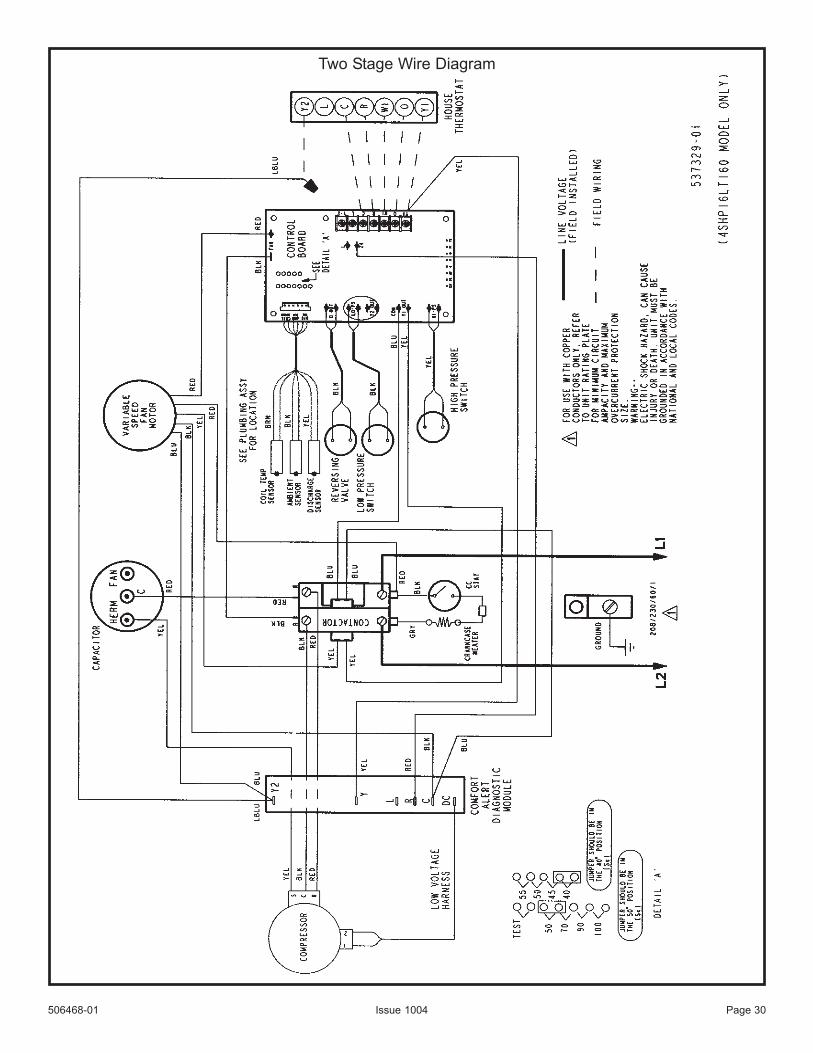
Two Stage Wire Diagram