INSTALLATION & OWNER’S MANUAL - Kaysun
16
INSTALLATION & OWNER’S MANUAL Cassettes 600x600 Type Thank you very much for purchasing our air conditioner, Before using your air conditioner, please read this manual carefully and keep it for future reference. KFC-CI-2T-300D KFC-CI-2T-500D KFC-CI-4T-300D KFC-CI-4T-500D KFC-CI-2T-300D1 KFC-CI-2T-500D1 KFC-CI-4T-300D1 KFC-CI-4T-500D1
Transcript of INSTALLATION & OWNER’S MANUAL - Kaysun

INSTALLATION & OWNER’S MANUAL
Cassettes 600x600 Type
Thank you very much for purchasing our air conditioner, Before using your air conditioner, please read this manual carefully and keep it for future reference.
KFC-CI-2T-300DKFC-CI-2T-500DKFC-CI-4T-300D
KFC-CI-4T-500DKFC-CI-2T-300D1KFC-CI-2T-500D1
KFC-CI-4T-300D1KFC-CI-4T-500D1

Installation & Owner’s Manual
1
CONTENTS PAGE
PRECAUTIONS ........................................................................ 1
INSTALLATION INFORMATION ............................................... 2
PARTS NAMES ......................................................................... 2
ATTACHED FITTINGS .............................................................. 3
FAN COIL UNIT INSTALLATION .............................................. 4
CONNECT THE DRAIN PIPE ................................................... 7
WIRING ..................................................................................... 8
TEST OPERATION ................................................................... 9
MAINTENANCE ...................................................................... 10
TROUBLESHOOTING ............................................................ 11
Be sure to be in conformity with the local, national and international laws and regulations.
Read "PRECAUTIONS" carefully before installation.
The following precautions include important safty items. Observe them and never forget.
Keep this manual in a handy place for future reference.
Before out from factory, FAN COIL UNIT (AIR UNITS) has passed Fan Coil Overpressure Resistant Test, Statically and Dynamically Balanced Adjustment, Noise Test, Air (cool) Volume Test, Electric Property Test, Outline Quality Detection.
The safety precautions listed here are divided into two categories. In either case, important safety information is listed which must be read carefully.
After completing the installation, make sure that the unit operates properly during the start-up operation. Please instruct the customer on how to operate the unit and keep it maintained.
Be sure only trained and qualified service personnel to install, repair or service the equipment.Improper installation, repair, and maintenance may result in electric shocks, short-circuit, leaks, fire or other damage to the equipment.
WARNING
WARNING
CAUTIONFailure to observe a caution may result in injury or damage to the equipment.
.
Install according to this installation instructions strictly. If installation is defective, it will cause water leakage, electrical shock and fire.
When installing the unit in a small room, take measures against to keep refrigerant concentration from exceeding allowable safety limits in the event of refrigerant leakage. Contact the place of purchase for more information. Excessive refrigerant in a closed ambient can lead to oxygen deficiency.
Use the attached accessories parts and specified parts for installation. otherwise, it will cause the set to fall, water leakage, electrical shock and fire.
The appliance must be installed 2.3m above floor.
The appliance shall not be installed in the laundry.
Before obtaining access to terminals, all supply circuits must be disconnected.
The appliance must be positioned so that the plug is accessible.
The enclosure of the appliance shall be marked by word, or by symbols, with the direction of the fluid flow.
For electrical work, follow the local national wiring standard, regulation and this installation instructions. An independent circuit and single outlet must be used. If electrical circuit capacity is not enough or defect in electrical work, it will cause electrical shock fire.
Use the specified cable and connect tightly and clamp the cable so that no external force will be acted on the terminal. If connection or fixing is not perfect, it will cause heat-up or fire at the connection.
Wiring routing must be properly arranged so that control board cover is fixed properly. If control board cover is not fixed perfectly, it will cause heat-up at connection point of terminal, fire or electrical shock.
If the supply cord is damaged, it must be replaced by the manufacture or its service agent or a similarly qualified person in order to avoid a hazard.
An all-pole disconnection switch having a contact separation of at least 3mm in all poles should be connected in fixed wiring.
When carrying out piping connection, take care not to let air substances go into refrigeration cycle. Otherwise, it will cause lower capacity, abnormal high pressure in the refrigeration cycle.
Do not modify the length of the power supply cord or use of extension cord, and do not share the single outlet with other electrical appliances. Otherwise, it will cause fire or electrical shock.
If the water leaks during installation, ventilate the area immediately.
After completing the installation work, check that the water does not leak.
The cool water in the unit is not lower than 3°C, hot water is not higher than 75°C. Water in the unit must clean, air quality must meet to the standard of PH=6.5~7.5.
1. PRECAUTIONS
Failure to observe a warning may result in serious injuries.

Installation & Owner’s Manual
2
Ground the air conditioner.Do not connect the ground wire to gas or water pipes, lightning rod or a telephone ground wire. Incomplete grounding may result in electric shocks.
Be sure to install an earth leakage breaker.Failure to install an earth leakage breaker may result in electric shocks.
Connect the outdoor unit wires, then connect the indoor unit wires. You are not allow to connect the air conditioner with the power source until wiring and piping the air conditioner is done.
While following the instructions in this installation manual, install drain piping in order to ensure proper drainage and insulate piping in order to prevent condensation.Improper drain piping may result in water leakage and property damage.
Install the indoor and outdoor units, power supply wiring and connecting wires at least 1 meter away from televisions or radios in order to prevent image interference or noise.Depending on the radio waves, a distance of 1 meter may not be sufficient enough to eliminate the noise.
This appliance is not intended for use by persons (including children) with reduced physical,sensory or mental capabilities, or lack of experience and knowledge, unless they have been given supervision or instruction concerning use of the appliance by a person responsible for their safety.
DISPOSAL: Do not dispose this product as unsor-ted municipal waste. Collection of such waste sepa-rately for special treatment is necessary.
Don't install the air conditioner in the following locations:
There is petrolatum existing.
There is salty air surrounding (near the coast).
There is caustic gas (the sulfide, for example) existing in the air (near a hot spring).
The Volt vibrates violently (in the factories).
In buses or cabinets.
In kitchen where it is full of oil gas.
There is strong electromagnetic wave existing.
There are inflammable materials or gas.
There is acid or alkaline liquid evaporating.
Other special conditions.
CAUTION 2. INSTALLATION INFORMATION
3. PARTS NAMES
Four-way Cassette
Four-way Cassette (compact)
Main body
Main body
Panel
lug
Influent value of cooling water collectorWater return orifice for plastic water tray
Effluent value of cooling water collector
Iffluent value of heating water collector
drain orifice
Effluent value of heating water collector
Panel
Iffluent value of heating water collector
Effluent value of heating water collector
Water return orifice for plastic water tray
lug
drain orifice
water heighgage
Influent value of cooling water collector
Effluent value of cooling water collector
To install properly, please read this "installation manual" at first.
The air conditioner must be installed by qualified persons.
When installing the indoor unit or its tubing, please follow this manual as strictly as possible.
If the air conditioner is installed on a metal part of the building, it must be electrically insulated according to the relevant standards to electrical appliances.
When all the installation work is finished, please turn on the power only after a thorough check.
Regret for no further announcement if there is any change of this manual caused by product improvement.

Installation & Owner’s Manual
3
4. ATTACHED FITTINGSPlease check whether the following fittings are of full scope. If there are some spare fittings, please restore them carefully.
NAME SHAPE Four-way Cas-sette
Four-way Cassette (compact)
INSTALLATION FITTINGS
1. Expansible hook 4 4
2. Installation hook 4 4
3. Installation paper board 1 1
4. Bolt M6 4
Tubing & Fittings 5. Soundproof / insulation sheath 2 2
Drainpipe Fittings
6. Out-let pipe pipe 1 1
7. Out-let pipe sheath 1
8. Out-let pipe clasp 1 1
9. Tightening band 20 20
Remote controller & Its Frame
10. Remote controller 1 1
11. Frame 1 1
12. Mounting screw (ST2.9*10-C-H) 2 2
13. Alkaline dry batteries (AM4) 2 2
Others
14. Installation&owner’s manual This manual 1 1
15. Remote controller manual 1 1
Installation & Owner’s Manual
4
5. FAN COIL UNIT INSTALLATION
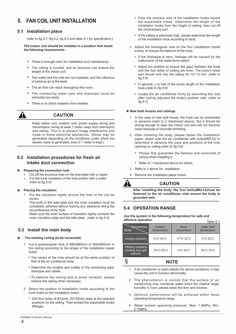
5.1 Installation place(refer to fig.5-1, fig.5-2, fig.5-3 and table 5-1 for specification.)
The indoor unit should be installed in a location that meets the following reauirements:
There is enough room for installation and maintenance.
The ceiling is horiztal, and its structure can endure the weight of the indoor unit.
The outlet and the inlet are not impeded, and the influence of external air is the least.
The air flow can reach throughout the room.
The connecting water pipe and drainpipe could be extracted out easily.
There is no direct radiation from heaters.
Keep indoor unit, outdoor unit, power supply wiring and transmission wiring at least 1 meter away from televisions and radios. This is to prevent image interference and noise in those electrical appliances. (Noise may be generated depending on the conditions under which the electric wave is generated, even if 1 meter is kept.)
Cut off the knockout hole on the side plate with a nipper.Cut the inner insulation of the hole portion with a cutter. (refer to fig.5-4)
Put the insulation tightly around the hole of the unit as shown.The ends of the side plate and the inner insulation must be completely adhered without leaving any clearance along the circumference of the hole.Make sure the inner surface of insulation tightly contacts the inner insulation edge and the side plate. (refer to fig.5-5)
The center of the hole should be at the same position of that of the air conditioner body.
Determine the lengths and outlets of the connecting pipe, drainpipe and cables.
To balance the ceiling and to avoid vibration, please enforce the ceiling when necessary.
Drill four holes of Φ12mm, 50~55mm deep at the selected positions on the ceiling. Then embed the expansible hooks (fittings).
1 Cut a quadrangular hole of 880x880mm or 600x600mm in the ceiling according to the shape of the installation paper board.
2 Select the position of installation hooks according to the hook holes on the installation board.
Preparing the connection hole
Placing the insulation
The existing ceiling (to be horizontal)
CAUTION
5.2 Installation procedures for fresh air intake duct connection
••
•
5.3 Install the main body
Face the concave side of the installation hooks toward the expansible hooks. Determine the length of the installation hooks from the height of ceiling, then cut off the unnecessary part.
If the ceiling is extremely high, please determine the length of the installation hook according to facts.
If the drainpipe is awry, leakage will be caused by the malfunction of the water-level switch.
Adjust the position to ensure the gaps between the body and the four sides of ceiling are even. The body's lower part should sink into the ceiling for 10~12 mm. (refer to fig.5-6)
In general, L is half of the screw length of the installation hook.(refer to fig.5-6)
Locate the air conditioner firmly by wrenching the nuts after having adjusted the body's position well. (refer to fig.5-7)
Please first guarantee the flatness and horizontal of ceiling when installing it.
Refer to 1 mentioned above for others.
After installing the body, the four bolts(M6x12)must be fastened to the air conditioner onto ensure the body is grounded well.
Use the system in the following temperature for safe and effective operation. Table 5-1
3 Adjust the hexangular nuts on the four installation hooks evenly, to ensure the balance of the body.
1 In the case of new built house, the hook can be embedded in advance (refer to 2 mentioned above). But it should be strong enough to bear the indoor unit and will not become loose because of concrete shrinking.
2 After installing the body, please fasten the installation paper board onto the air conditioner with bolts(M6X12) to determine in advance the sizes and positions of the hole opening on ceiling.(refer to fig.5-8)
1 If air conditioner is used outside the above conditions, it may cause the unit to function abnormally.
2 The phenomenon is normal that the surface of air conditioning may condense water when the relative larger humidity in room, please close the door and window.
3 Optimum performance will be achieved within these operating temperature range.
4 Water system operating pressuer: Max: 1.6MPa, Min: 0.15MPa.
3 Refer to 3 above for installation.
4 Remove the installation paper board.
New built houses and ceilings
CAUTION
5.4 OPERATION RANGE
Temperature Mode
Outdoor temperature
Room temperature
water inlet temperature
Cooling operation 0°C~43°C 17°C~32°C 3°C~20°C
NOTE
•
•
•
•
•
•
•
•
Heating operating (cooling only type
without)-15°C~24°C 0°C~30°C 30°C~75°C

Installation & Owner’s Manual
5
L
45
300
190>3
30
220
150
160
210
Four-way CassetteFIGURES
Tubing side Drain sideConnecting point of drain pipe Water pipe joint
Ceiling
Ground
Outlet OutletInlet
880mm (ceiling hole)
Panel
780(Hook-location)
840(Body)
950(Panel)
>1000mm
>1000mm
>100
0mm
>100
0mm
(Unit: mm)
Inner insulation
Inner insulation
Insulation(local)
Central hole
Grid switch
All the pictures in this manual are for explanation purpose only. They may be slightly different from the air conditioner you purchased(depend on model). The actual shape shall prevail.
Bolt M6X12 Installation paper board
Body
Insulation(local)
Side plate
Insulation(local)
Ceiling
10-1
2mm
Body
±10mm
Slit
Side plate
Fig.5-1
Fig.5-3
Fig.5-5
Fig.5-8 Fig.5-9
NOTE
Fig.5-10 Fig.5-11
Fig.5-6 Fig.5-7
Fig.5-2
Fig.5-4
680(
Hoo
k-lo
catio
n)
840(
Bod
y)
950(
Pan
el)
4000
~250
0(m
m)

Installation & Owner’s Manual
6
261
213
>300
190
124
261
213
>300 190
124
110 157
NOTE
Four-way Cassette (compact)
Four-Pipe
Two-Pipe
FIGURES 2Drain side
545(Hook-location)52
3(H
ook-
loca
tion)
575(
Bod
y)
647(
Pan
el)
2800
~230
0(m
m)
575(Body)
647(Panel)
Body
Central hole
Hook holeFixing hole
Drip tray
Drip tray
(Accessory)
Installation paper board
Ceiling
2800
~230
0(m
m)
Water pipe joint
Connecting point of drain pipe
installation paper board
Ceiling
Water pipe joint Connecting point of drain pipe
Ground
Ground
Panel
Panel
Outlet
Outlet
600mm (ceiling hole)
600mm (ceiling hole)
Outlet
Outlet
Inlet
Inlet
(Unit: mm)
Tubing side
FIGURES 3
Fig.5-12
Fig.5-13
Fig.5-16
Fig.5-17
Fig.5-14
Fig.5-15
Fig.5-18
Before suspending installation, please connect the three-way valve and its connected pipe to the main unit.There are not three-way valve and the connected pipe be attached inside. Yours may different from the figure as shows.
Note: the cover boards and the drip tray are accessories just for the customers to choose.
Height of the front panel:
H
Type H(mm)
Four-way cassette 45
Four-way cassette (compact) 50

Installation & Owner’s Manual
7
5.4 Install The Panel6. CONNECT THE DRAIN PIPE
CAUTION
CAUTION
CAUTION
NOTE
CAUTION
Never put the panel face down on floor or against the wall, or on bulgy objects.
Never crash or strike it.
Don’t use forcing strength to crack the water-pumping pipe.
The joints in drain system must be sealed to avoid water leakage.
All the pictures in this manual are for explanation purpose only. They may be slightly different from the air conditioner you purchased(depend on model). The actual shape shall prevail.
Do not coil the wiring of the swing motor into the seal sponge.
1 Remove the air-in grill.
2 Remove the installation covers at the four corners
3 Install the panel
4 Hang the air-in grill to the panel, then connect the lead terminator of the swing motor and that of the control box with corresponding terminators on the body respectively.
5 Relocate the air-in grill in the procedure of reversed order.
6 Relocate the installation cover.
Slide two grill switches toward the middle at the same time, and then pull them up. (Refer to fig.5-9)
Draw the grill up to an angle of about 45°, and remove it. (Refer to fig.5-10)
6.1 Install the drain pipe of indoor unit
1) The drainpipe can use PVC pipe (external diameter about 37~39mm, inner diameter is 32mm).
2) Joint drainpipe connector to the end side of water pumping pipe, and fix drainpipe together with water outflow pipe and thermal insulation tube by clasp of water outflow pipe (attached).
3) Water-pumping pipe and drainpipe from main body must be wrapped by insulation tube evenly, and bound by tighten band for obstructing air getting in and coagulation.
4) Prevent from water backflow into unit inside during shutdown, the drain pipe shall place down side and drain water to outdoor (drain side), the gradient of the drain pipe should be higher than (1/100), without salient and water remain.(Refer to Fig.6-1 a)
5) When connecting drainpipe, don’t drag the pipe that would pull the main unit. For this, please arrange bearing points every 0.8 to 1.0 meter to avoid pipe be bended (See Fig.6-1 b).
6) When connect a lengthen drainpipe, apply protective tube to wrap its indoor parts for ensuring the lengthen part connected tightly.
7) In case the drainpipe outlet is higher than pumping connective pipe of the main body, the drainpipe must be arranged upwards vertically by using connective assembly of the water outlet for vertical bending, and the height of the drainpipe shall set to the defrosting pan surface no more than 1000mm (four-way cassette) or 600mm (slim four-way cassette), otherwise, too much backflow while shutdown would leads to overflow (Refer to Fig.6-2).
8) Base on the actual requirement to bend piping, and use connective assembly of water outlet in terminal box for pipe layout.
9) The height from floor to the end of drainpipe or the bottom of drain slot must more than 50 mm. Don’t immerse the end of drainpipe or the bottom of drain slot into water. When drain condensate liquid to raceway, please bend the drainpipe to a U-sharped hydroseal for avoiding stench transmitted by drainpipe to indoor.
Wrench off the bolts, loose the rope of the installation covers, and remove them. (Refer to fig.5-11)
Align the swing motor on the panel to the tubing joints of the body properly.
Fix hooks of the panel at swing motor and its opposite sides to the hooks of corresponding water receiver. Then hang the other two panel hooks onto corresponding hangers of the body.
Adjust the four panel hook screws to keep the panel horizontal, and screw them up to the ceiling evenly.
Regulate the panel in the direction of the arrow slightly to fit the panel's center to the center of the ceiling's opening. Guarantee that hooks of four corners are fixed well.
Keep fastening the screws under the panel hooks, until the thickness of the sponge between the body and the panel's outlet has been reduced to about 4~6mm. The edge of the panel should contact with the ceiling well.
Fasten the rope of installation cover on the bolt of the installation cover.
Press the installation cover into the panel slightly.
If the gap between the panel and ceiling still exists after fastening the screws, the height of the indoor unit should be modified again.
You can modify the height of the indoor unit through the openings on the panel's four corners, if the lift of the indoor unit and the drainpipe is not influenced.

Installation & Owner’s Manual
8
6.2 Drainage test
7.1 Connect the cable
7. WIRING
Check whether the drainpipe is unhindered
New built house should have this test done before paving the ceiling.
1. Remove the test cover, and stow water of about 2000ml to the water receiver through the stow tube.
2. Turn on the power, and operate the air conditioner under the "COOLING" mode. Listen to the sound of the drain pump. Check whether the water is discharged well (a lag of 1min is allowed before discharging, according to the length of the drain pipe), and check whether water leaksfrom the joints.
CAUTIONS: If there is any malfunction, please resolve it immediately.
3. Stop the air conditioner for there minutes, check if everything is ok. If the drain hose is located unreasonable, water overflow will cause the Alarm indicator lamp flashing (For both cooling and heating type or cooling only type), even the water leak out from the water receiver.
4. Check the drain pump whether drain water immediately when alarm sound for the high water lever. If the water lever can't come down below to the limited water lever, the air conditioner will stop. Restart it until turn off the power and drain off all the water.
Dissemble the bolts from the cover.(If there isn't a cover on the outdoor unit, disassemble the bolts from the maintenance board, and pull it in the direction of the arrow to remove the protection board.)
Connect the connective cables to the terminals as identified with their respective mached numbers on the terminal block of indoor and outdoor units.
Re-install the cover or the protection board.
Gradient: higher than 1/100
four-way cassette:
slim four-way cassette:
<200mm
<200mm
0.8-1.0m
0.8-1.0m
Lean over 1/100
Lean over 1/100
Pump-pipe clasp (the fittings)
Pump-pipe clasp (the fittings)
Max
. 100
0mm
Max
. 600
mm
Fig.6-1
Fig.6-2
0.8~1.0 m
>1.0 m
a
b
5. Turn off the power, drain the water away.
The drain plug is used to empty the water-receiver for maintenance of the air conditioner. Please stuff it imposition at all times during operation to avoid leakage.
The air conditioner should use separate power supply with rated voltage.
The external power supply to the air conditioner should have ground wiring, which is linked to the ground wiring of the indoor and outdoor unit.
The wiring work should be done by qualified persons according to circuit drawing.
An all-pole disconnection device which has at least 3mm separation distance in all pole and a residual current device (RCD) with the rating of above 10mA shall be incorporated in the fixed wiring according to the national rule.
The appliance shall be installed in accordance with national wiring regulations.
Be sure to locate the power wiring and the signal wring well to avoid cross-disturbance.
Do not turn on the power until you have checked carefully after wiring.
Remark per EMC Directive 2004/108/ECFor to prevent flicker impressions during the start of the compressor (technical process), following installation conditions do apply.1. The power connection for the air conditioner has to be
done at the main power distribution. The distribution has to be of alow impedance, normally the required impedance reaches at a 32 A fusing point.
2. No other equipment has to be connected with this power line.
3. For detailed installation acceptance please refer to your power supplier, if restrictions do apply for products like washing machines, air conditioners or electrical ovens.
4. For power details of the air conditioner refer to the rating plate of the product.
5. For any question contact your local dealer.
CAUTION
NOTE

Installation & Owner’s Manual
9
NL
NL
432
1N
L3
21
Table 7-1
AIR FLOW(m3/h) 510~2550
POWERPHASE 1-phase
FREQUENCY AND VOLT 220-240V~ 50Hz
CIRCUIT BREAKER/FUSE(A) 15/15
INDOOR UNIT POWER WIRING(mm2)
BELOW 20M Twisted pairwire 2.5mm2
BELOW 50M Twisted pairwire 6mm2
GROUND WIRING(mm2) 2.5
The power cord type designation is H05RN-F or above.
1. The test operation must be carried out after the entire installation has been completed.
2. Please confirm the following points before the test operation:
3. According to the user's requirement, install the remote controller frame where the remote controller's signal can reach the indoor unit smoothly.
4. Test operation
The indoor unit and outdoor unit are installed properly.
Tubing and wiring are correctly completed.
The water pipe system is leakage-checked.the drainage is unimpeded.
The heating insulation works well.
The ground wiring is connected correctly.
The length of the tubing has been recorded.
The power voltage fits the rated voltage of the air conditioner.
There is no obstacle at the outlet and inlet of the outdoor and indoor units.
The air conditioner is pre-heated by turning on the power.
Set the air conditioner under the mode of "COOLING" with the remote controller, and check the following points. If there is any malfunction, please resolve it according to the chapter "Troubleshooting" in this manual.
a. Whether the switch on the remote controller works well.b. Whether the buttons on the remote controller works well.c. Whether the air flow louver moves normally.d. Whether the room temperature is adjusted well.e. Whether the indicator lights normally.f. Whether the temporary buttons works well.g. Whether the drainage is normal.h. Whether there is vibration or abnormal noise during
operation.I. Whether the air conditioner heats well in the case of the
HEATING/COOLING type.
In the event, client applies for the Remote Control Function:Firstly, dial code SW3 must switch off.Secondly, connect the signal wires to CN17.Finally, the defrost indicator in LCD flashing in 5Hz at the time remote controlling indoor unit’s switch be dialed to OFF.
A protection feature prevents the air conditioner from being activated for approximately 3 minutes when it is restarted immediately after shut off.
If the supply cord is damaged, it must be replaced by the manufacturer or its service agent or a similarly qualified person in order to avoid a hazard.
Pla
n eo
f Ind
oor U
nit
Sig
nal R
eciv
er
5-co
re C
onne
ctin
g G
roup
5-co
re S
hiel
d C
able
5X
0.5m
m2
Wire
Con
trolle
rVA
LVE
VALV
E-C
VALV
E-H
Pow
er:2
20-2
40v~
50H
z3
core
3X
2.5m
m2
Ele
ctric
Con
rolli
ng B
ox’s
Plu
g C
n 10
Indo
or U
nit E
lect
ric C
onro
lling
Box
Mai
n B
oard
Pow
er:2
20-2
40v~
50H
z3
core
3X
2.5m
m2
Pow
er:2
20-2
40v~
50H
z3
core
3X
2.5m
m2
Four-way CassetteTwo-Pipe(compact)
Four-way CassetteFour-Pipe(compact)
Four-way Cassette
10-c
ore
Con
nect
ing
Wire
Gro
up
7.2 Wiring figure
NOTE
8. TEST OPERATION
CAUTION
AIR
CO
ND
ITIO
NE
AN
D W
IRE
CO
NTR
OLE
R W
IRIN
G
Installation & Owner’s Manual
10
9. MAINTENANCE
CAUTION
Before you clean the air conditioner, be sure the power supply is off.
Check if the wiring is not broken off or disconnected.
Disconnect the power supply before c lean ing and maintenance. Use dry cloth to clean the unit.
A wet cloth may be used to clean the indoor unit if it is very dirty.
Never use a damp cloth on the remote controller.
Do not use a chemically-treted duster for wiping or leave such material on the unit for long.it may damage or fade the surface of the unit.
Do not use benzine, thinner, polishing powder, or similar solvents for cleaning. These may cause the plastic surface to crack or deform.
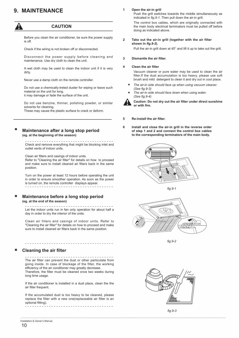
1 Open the air-in grill
2 Take out the air-in grill (together with the air filter shown in fig.9-2).
3 Dismantle the air filter.
4 Clean the air filter
5 Re-install the air filter.
6 Install and close the air-in grill in the reverse order of step 1 and 2 and connect the control box cables to the corresponding terminators of the main body.
Push the grill switches towards the middle simultaneously as indicated in fig.9-1. Then pull down the air-in grill.The control box cables, which are originally connected with the main body electrical terminators must be pulled off before doing as indicated above.
Pull the air-in grill down at 45° and lift it up to take out the grill.
Vacuum cleaner or pure water may be used to clean the air filter.If the dust accumulation is too heavy, please use soft brush and mild detergent to clean it and dry out in cool place.
Caution: Do not dry out the air filter under direct sunshine or with fire.
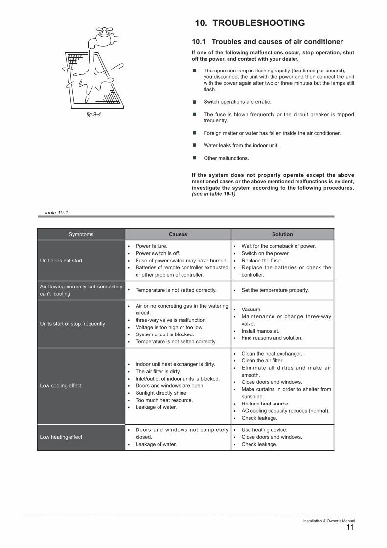
The air-in side should face up when using vacuum cleaner.(See fig.9-3)The air-in side should face down when using water. (See fig.9-4)
Check and remove everything that might be blocking inlet and outlet vents of indoor units.
Clean air filters and casings of indoor units. Refer to "Cleaning the air filter" for details on how to proceed and make sure to install cleaned air filters back in the same position.
Turn on the power at least 12 hours before operating the unit in order to ensure smoother operation. As soon as the power is turned on, the remote controller displays appear.
Let the indoor units run in fan only operation for about half a day in order to dry the interior of the units.
Clean air filters and casings of indoor units. Refer to "Cleaning the air filter" for details on how to proceed and make sure to install cleaned air filters back in the same position.
The air filter can prevent the dust or other particulate from going inside. In case of blockage of the filter, the working efficiency of the air conditioner may greatly decrease.Therefore, the filter must be cleaned once two weeks during long time usage.
If the air conditioner is installed in a dust place, clean the the air filter frequent.
If the accumulated dust is too heavy to be cleaned, please replace the filter with a new one(replaceable air filter is an optional fitting).
Maintenance after a long stop period (eg. at the beginning of the season)
Maintenance before a long stop period (eg. at the end of the season)
Cleaning the air filter
fig.9-1
fig.9-2
fig.9-3
Installation & Owner’s Manual
11
fig.9-4
table 10-1
10. TROUBLESHOOTING
10.1 Troubles and causes of air conditionerIf one of the following malfunctions occur, stop operation, shut off the power, and contact with your dealer.
If the system does not properly operate except the above mentioned cases or the above mentioned malfunctions is evident, investigate the system according to the following procedures. (see in table 10-1)
The operation lamp is flashing rapidly (five times per second),you disconnect the unit with the power and then connect the unit with the power again after two or three minutes but the lamps still flash.
Switch operations are erratic.
The fuse is blown frequently or the circuit breaker is tripped frequently.
Foreign matter or water has fallen inside the air conditioner.
Water leaks from the indoor unit.
Other malfunctions.
Symptoms Causes Solution
Unit does not start
Power failure. Power switch is off. Fuse of power switch may have burned. Batteries of remote controller exhausted
or other problem of controller.
Wait for the comeback of power. Switch on the power. Replace the fuse. Replace the batteries or check the
controller.
Air flowing normally but completely can't cooling
Temperature is not setted correctly. Set the temperature properly.
Units start or stop frequently
Air or no concreting gas in the watering circuit.
three-way valve is malfunction. Voltage is too high or too low. System circuit is blocked. Temperature is not setted correctly.
Vacuum. Maintenance or change three-way
valve. Install manostat. Find reasons and solution.
Low cooling effect
Indoor unit heat exchanger is dirty. The air filter is dirty. Inlet/outlet of indoor units is blocked. Doors and windows are open. Sunlight directly shine. Too much heat resource. Leakage of water.
Clean the heat exchanger. Clean the air filter. Eliminate all dirties and make air
smooth. Close doors and windows. Make curtains in order to shelter from
sunshine. Reduce heat source. AC cooling capacity reduces (normal). Check leakage.
Low heating effect Doors and windows not completely
closed. Leakage of water.
Use heating device. Close doors and windows. Check leakage.
Installation & Owner’s Manual
12
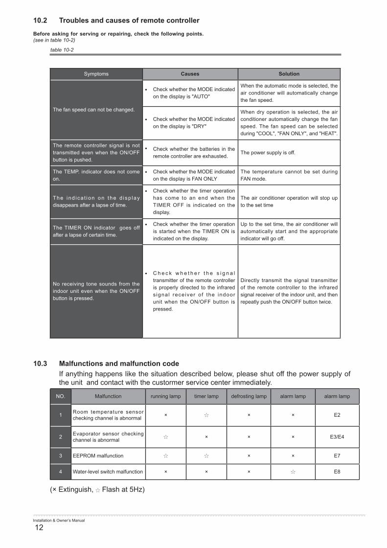
10.2 Troubles and causes of remote controller
10.3 Malfunctions and malfunction codeIf anything happens like the situation described below, please shut off the power supply of the unit and contact with the custormer service center immediately.
(× Extinguish, Flash at 5Hz)
Before asking for serving or repairing, check the following points. (see in table 10-2)
table 10-2
Symptoms Causes Solution
The fan speed can not be changed.
Check whether the MODE indicated on the display is "AUTO"
When the automatic mode is selected, the air conditioner will automatically change the fan speed.
Check whether the MODE indicated on the display is "DRY"
When dry operation is selected, the air conditioner automatically change the fan speed. The fan speed can be selected during "COOL", "FAN ONLY", and "HEAT".
The remote controller signal is not transmitted even when the ON/OFF button is pushed.
Check whether the batteries in the remote controller are exhausted.
The power supply is off.
The TEMP. indicator does not come on.
Check whether the MODE indicated on the display is FAN ONLY
The temperature cannot be set during FAN mode.
The ind i ca t i on on the d i sp lay disappears after a lapse of time.
Check whether the timer operation has come to an end when the TIMER OFF is indicated on the display.
The air conditioner operation will stop up to the set time
The TIMER ON indicator goes off after a lapse of certain time.
Check whether the timer operation is started when the TIMER ON is indicated on the display.
Up to the set time, the air conditioner will automatically start and the appropriate indicator will go off.
No receiving tone sounds from the indoor unit even when the ON/OFF button is pressed.
C h e c k w h e t h e r t h e s i g n a l transmitter of the remote controller is properly directed to the infrared s ignal rece iver o f the indoor unit when the ON/OFF button is pressed.
Directly transmit the signal transmitter of the remote controller to the infrared signal receiver of the indoor unit, and then repeatly push the ON/OFF button twice.
NO. Malfunction running lamp timer lamp defrosting lamp alarm lamp alarm lamp
1 Room temperature sensor checking channel is abnormal × × × E2
2 Evaporator sensor checking channel is abnormal × × × E3/E4
3 EEPROM malfunction × × E7
4 Water-level switch malfunction × × × E8

Installation & Owner’s Manual
13
Four-way Cassette (compact)
(× Extinguish, ☆ Flash at 5Hz)
NO. Malfunction running lamp timer lamp defrosting lamp alarm lamp
1Room temperature sensor checking channel is abnor-mal
X ☆ X X
2 Evaporator sensor checking channel is abnormal ☆ X X X
3 EEPROM malfunction ☆ ☆ X X
4 Water-level switch malfunction X X X ☆
5Indoor unit switch at long-range controller is dialed to OFF
X X ☆ X

2020001A9002 V1.0MDV08IU-026DW