
Installation & Operation Manual KBM A
24
*IMPORTANT This drive is factory set for: 1. 60 Hz Motors, for 50 Hz motors, see Section 7.4, on page 17 and 18. 2. 208/230 Volt AC line input, for 115 VAC operation, see Section 7.1, on page 16. AC MOTOR SPEED CONTROL KBMA SERIES • NEMA 1 / IP 50 Hybrid Drive ™ Installation & Operation Manual KBMA ™ See Safety Warning, on page 5. The information contained in this manual is intended to be accurate. However, the manufacturer retains the right to make changes in design which may not be included herein. Notes: 1. UL approved as an electronic overload protector for motors. 2. Model KBMA-24DF contains a built-in AC line Class A RFI (EMI) filter which meets CE Council Directive 89/336/EEC Industrial Requirement. For Class B Residential Requirement, the KBRF-300 filter (Part No. 9484) must be used (externally mounted). 3. Model KBMA-24D only. Adjustable Frequency Drives 2 3 This Manual Covers Models KBMA-24D, 24DF 2 for 1/8 HP thru 1HP 3-Phase AC Motors rated 208 – 230 VAC, 50* & 60 Hz NEMA-1 / IP-50 Operates from 115* and 208/230 Volt 50/60 Hz AC Line Variable Speed / Soft-Start with Electronic Motor Overload Protection 1 The QR code link to this manual is also located on the inside of the drive cover. © 2011 KB Electronics, Inc. (see back cover)
Transcript of Installation & Operation Manual KBM A

*IMPORTANT
This drive is factory set for:
1. 60 Hz Motors,for 50 Hz motors, seeSection 7.4, on page 17and 18.
2. 208/230 Volt AC line input,for 115 VAC operation, seeSection 7.1, on page 16.
AC MOTOR SPEED CONTROL
KBMA SERIES • NEMA 1 / IP 50
Hybrid Drive™
Installation & Operation Manual
KBMA™
See Safety Warning,on page 5.
The information contained in this manual is intended to be accurate. However, the manufacturer retainsthe right to make changes in design which may not be included herein.
Notes: 1. UL approved as an electronic overload protector for motors. 2. ModelKBMA-24DF contains a built-in AC line Class A RFI (EMI) filter which meets CE CouncilDirective 89/336/EEC Industrial Requirement. For Class B Residential Requirement,the KBRF-300 filter (Part No. 9484) must be used (externally mounted).3. Model KBMA-24D only.
Adjustable Frequency Drives
2 3
This Manual Covers Models KBMA-24D, 24DF 2
for 1/8HP thru 1HP 3-Phase AC Motors rated 208 –230 VAC, 50* & 60 Hz
NEMA-1 / IP-50
Operates from 115* and 208/230 Volt 50/60 Hz AC LineVariable Speed / Soft-Start with Electronic Motor Overload Protection1
The QR code link to thismanual is also located onthe inside of the drive cover.
© 2011 KB Electronics, Inc.(see back cover)

Table of Contents
Section Page
1 Quick-Start Instructions . . . . . . . . . . . . . . . . . . . . . . . . . . . . . . . . . . . . . . . . . . . . . . . . . . . . . . . . . . . . . . . . . . . . . 4
2 Safety Warning . . . . . . . . . . . . . . . . . . . . . . . . . . . . . . . . . . . . . . . . . . . . . . . . . . . . . . . . . . . . . . . . . . . . . . . . . . . 5
3 Introduction . . . . . . . . . . . . . . . . . . . . . . . . . . . . . . . . . . . . . . . . . . . . . . . . . . . . . . . . . . . . . . . . . . . . . . . . . . . . . 6
4 Important Application Information . . . . . . . . . . . . . . . . . . . . . . . . . . . . . . . . . . . . . . . . . . . . . . . . . . . . . . . . . . . 13
5 Mounting Instructions . . . . . . . . . . . . . . . . . . . . . . . . . . . . . . . . . . . . . . . . . . . . . . . . . . . . . . . . . . . . . . . . . . . . . 14
6 Electrical Connections . . . . . . . . . . . . . . . . . . . . . . . . . . . . . . . . . . . . . . . . . . . . . . . . . . . . . . . . . . . . . . . . . . . . . 14
7 Setting Selectable Jumpers . . . . . . . . . . . . . . . . . . . . . . . . . . . . . . . . . . . . . . . . . . . . . . . . . . . . . . . . . . . . . . . . . 16
8 Recommended High Voltage Dielectric Withstand Testing (Hi-Pot Testing) . . . . . . . . . . . . . . . . . . . . . . . . . . . . . . 18
9 Drive Operation . . . . . . . . . . . . . . . . . . . . . . . . . . . . . . . . . . . . . . . . . . . . . . . . . . . . . . . . . . . . . . . . . . . . . . . . . . 20
10 Pilot Light and Diagnostic LEDs . . . . . . . . . . . . . . . . . . . . . . . . . . . . . . . . . . . . . . . . . . . . . . . . . . . . . . . . . . . . . . 20
11 Trimpot Adjustments . . . . . . . . . . . . . . . . . . . . . . . . . . . . . . . . . . . . . . . . . . . . . . . . . . . . . . . . . . . . . . . . . . . . . . 21
Limited Warranty . . . . . . . . . . . . . . . . . . . . . . . . . . . . . . . . . . . . . . . . . . . . . . . . . . . . . . . . . . . . . . . . . . . . . . . . . . . . 24
Tables Page
1 Optional Accessories . . . . . . . . . . . . . . . . . . . . . . . . . . . . . . . . . . . . . . . . . . . . . . . . . . . . . . . . . . . . . . . . . . . . . . . 8
2 General Performance Specifications . . . . . . . . . . . . . . . . . . . . . . . . . . . . . . . . . . . . . . . . . . . . . . . . . . . . . . . . . . . . 9
3 Electrical Ratings . . . . . . . . . . . . . . . . . . . . . . . . . . . . . . . . . . . . . . . . . . . . . . . . . . . . . . . . . . . . . . . . . . . . . . . . . . 9
4 Terminal Block Wire and Tightening Torque Specifications . . . . . . . . . . . . . . . . . . . . . . . . . . . . . . . . . . . . . . . . . . 14
5 Drive Operating Conditions and Run/Fault Relay Contact Status . . . . . . . . . . . . . . . . . . . . . . . . . . . . . . . . . . . . . 16
6 Drive Operating Conditions and LED Indications . . . . . . . . . . . . . . . . . . . . . . . . . . . . . . . . . . . . . . . . . . . . . . . . . 21
Figures Page
1 Quick-Start Connection Diagram . . . . . . . . . . . . . . . . . . . . . . . . . . . . . . . . . . . . . . . . . . . . . . . . . . . . . . . . . . . . . . 4
2 Mechanical Specifications . . . . . . . . . . . . . . . . . . . . . . . . . . . . . . . . . . . . . . . . . . . . . . . . . . . . . . . . . . . . . . . . . . 10
3 Cover Layout . . . . . . . . . . . . . . . . . . . . . . . . . . . . . . . . . . . . . . . . . . . . . . . . . . . . . . . . . . . . . . . . . . . . . . . . . . . . 11
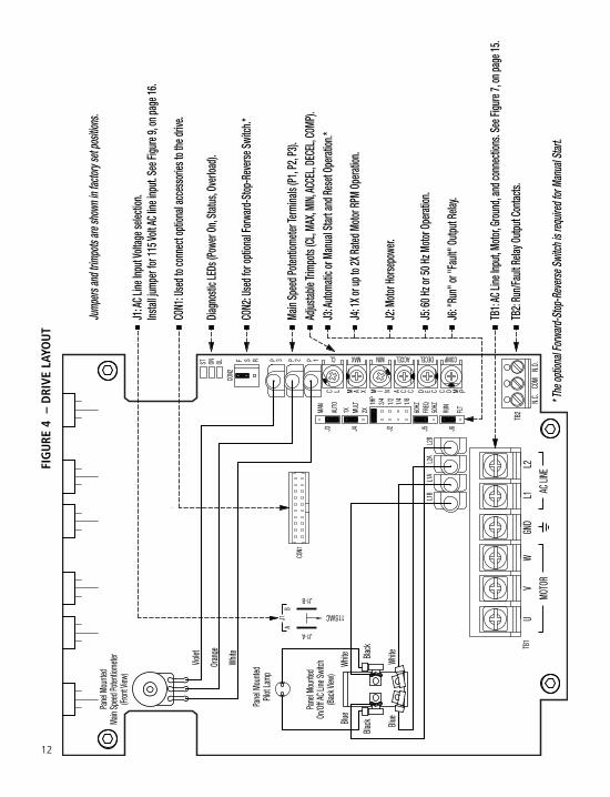
4 Drive Layout . . . . . . . . . . . . . . . . . . . . . . . . . . . . . . . . . . . . . . . . . . . . . . . . . . . . . . . . . . . . . . . . . . . . . . . . . . . . 12
5 Maximum Allowed Motor Torque vs. Speed . . . . . . . . . . . . . . . . . . . . . . . . . . . . . . . . . . . . . . . . . . . . . . . . . . . . 13
6 Open Ventilated Motor with External Fan Cooling . . . . . . . . . . . . . . . . . . . . . . . . . . . . . . . . . . . . . . . . . . . . . . . . 13
7 AC Line Input, Motor, and Ground Connections . . . . . . . . . . . . . . . . . . . . . . . . . . . . . . . . . . . . . . . . . . . . . . . . . 15
8 Run/Fault Relay Output Contacts Connections . . . . . . . . . . . . . . . . . . . . . . . . . . . . . . . . . . . . . . . . . . . . . . . . . . . 15
9 AC Line Input Voltage Selection (Jumper J1) . . . . . . . . . . . . . . . . . . . . . . . . . . . . . . . . . . . . . . . . . . . . . . . . . . . . 16
10 Motor Horsepower Selection (Jumper J2) . . . . . . . . . . . . . . . . . . . . . . . . . . . . . . . . . . . . . . . . . . . . . . . . . . . . . . 16
11 Automatic or Manual Start and Reset Selection (Jumper J3) . . . . . . . . . . . . . . . . . . . . . . . . . . . . . . . . . . . . . . . . 17
12 60 Hz or 50 Hz Motor Selection (Jumpers J4 and J5) . . . . . . . . . . . . . . . . . . . . . . . . . . . . . . . . . . . . . . . . . . . . . . 17
13 Available Torque vs. Output Frequency . . . . . . . . . . . . . . . . . . . . . . . . . . . . . . . . . . . . . . . . . . . . . . . . . . . . . . . . 17
14 120 Hz and 100 Hz Drive Output Frequency Selection (Jumpers J4 and J5) . . . . . . . . . . . . . . . . . . . . . . . . . . . . . 18
15 “Run” or “Fault” Output Relay Operation Selection (Jumper J6) . . . . . . . . . . . . . . . . . . . . . . . . . . . . . . . . . . . . . 18
16 Typical Hi-Pot Test Setup . . . . . . . . . . . . . . . . . . . . . . . . . . . . . . . . . . . . . . . . . . . . . . . . . . . . . . . . . . . . . . . . . . . 19
17 Minimum Speed Trimpot (MIN) Range . . . . . . . . . . . . . . . . . . . . . . . . . . . . . . . . . . . . . . . . . . . . . . . . . . . . . . . . . 21
ii

18 Maximum Speed Trimpot (MAX) Range . . . . . . . . . . . . . . . . . . . . . . . . . . . . . . . . . . . . . . . . . . . . . . . . . . . . . . . . 22
19 Acceleration Trimpot (ACCEL) Range . . . . . . . . . . . . . . . . . . . . . . . . . . . . . . . . . . . . . . . . . . . . . . . . . . . . . . . . . . 22
20 Deceleration Trimpot (DECEL) Range . . . . . . . . . . . . . . . . . . . . . . . . . . . . . . . . . . . . . . . . . . . . . . . . . . . . . . . . . . 22
21 Slip Compensation Trimpot (COMP) Range . . . . . . . . . . . . . . . . . . . . . . . . . . . . . . . . . . . . . . . . . . . . . . . . . . . . . 22
22 Current Limit Trimpot (CL) Range . . . . . . . . . . . . . . . . . . . . . . . . . . . . . . . . . . . . . . . . . . . . . . . . . . . . . . . . . . . . 23
23 I2t Trip Time vs. Motor Current . . . . . . . . . . . . . . . . . . . . . . . . . . . . . . . . . . . . . . . . . . . . . . . . . . . . . . . . . . . . . . 23
Items Included In this Package:KBMA Adjustable Frequency Drive, Installation and Operation Manual, Hardware Bag (containing Trimpot AdjustmentTool, AC Line Input Voltage Selection Jumper, and an extra Feed-Through Bushing), CE Approved Product InformationCard, and Warranty Registration Card, Mounting Template.
iii
230 VAC ControlsSuitable For Use On A Circuit Capable Of Delivering Not More Than 5 kA RMS Symmetrical Amperes,230 Volts Maximum.Use Copper Conductors Rated 75 ºC.Suitable for Operation in a Maximum Surrounding Air Temperature of 40 ºC.
UL Notice

See Figure 1. Also see Section 4 – Important Application Information, on page 13.
WARNING! Disconnect main power before making connections to the drive.
Note: It is recommended that both Feed-Through Bushings be used to connect the drive. If signal wiring (for theRun/Fault Relay Output Contacts or for a remote Main Speed Potentiometer) is required, it is recommended thatthe extra Feed-Through Bushing (supplied with the drive) be used to replace the center Hole Plug. Standard 3/4”fittings (not supplied) can also be used in lieu of the Feed-Through Bushings.
1.1 MOUNTING INSTRUCTIONS – See Section 5,on page 14.
1.2 AC LINE INPUT CONNECTION – Connect thesingle-phase AC line input to Terminal BlockTB1 (Terminals “L1”, “L2”), as shownin Figure 1. See Section 6.1, on pages 14and 15.
Application Note – Do not connect thisdrive to a GFCI. If operation with a GFCIis required, contact our Sales Department.
Note: The drive is factory set for 208/230Volt AC line input (Jumper J1 notinstalled). For 115 Volt AC line input,install Jumper J1 (supplied). See Section7.1, on page 16.
1.3 AC LINE FUSING – It is recommended that a fuse(s) or circuit breaker be installed in the AC line. Fuse eachconductor that is not at ground potential.For the recommended fuse size, see Table 3, on page 9. Also see Section 6.1, on pages 14 and 15.
1.4 GROUND CONNECTION – Connect the ground wire (earth) to Terminal Block TB1 (Terminal “GND”),as shown in Figure 1, above.
1.5 MOTOR CONNECTION – Connect the motor to Terminal Block TB1 (Terminals “U”, “V”, “W”), as shown inFigure 1, on page 4. (Special reactors may be required for cable lengths over 100 ft. (30 m) – consult ourSales Department.). See Section 6.3, on page 15.
4
1 QUICK-START INSTRUCTIONS
Important – You must read these simplified instructions before proceeding. These instructions are to be usedas a reference only and are not intended to replace the details provided herein. You must read the SafetyWarning, on page 5, before proceeding.
Note: This drive contains bus capacitors which must be reconditioned if the drive has been in storage for over1 year. To recondition the bus capacitors, apply the AC line, with the main speed potentiometer set to zero, fora minimum of 30 minutes.
FIGURE 1 – QUICK-START CONNECTION DIAGRAM
115* or 208/230 VoltSingle-Phase AC Line Input
see Section 6.1, on pages 14 and 15.
* For 115 VAC line, install Jumper J1 (supplied).
3-Phase, 208/230 VoltAC Induction Motor
see Section 6.3, on page 15.
AC LINEMOTOR
Motor
TB1 U V
Ground (Earth)see Section 6.2,
on page 15.
GNDW L1 L2

1.6 JUMPER SETTINGS – All jumpers have been factory set for most applications, as shown in Figure 4,on page 12. Some applications require setting of the jumpers in order to set the drive for a specificapplication. Jumper J2 must be set to match the horsepower of the motor being used. See Section 7, onpages 16 – 18.
1.7 60 Hz and 50 Hz MOTOR OPERATION – The drive is factory set for 60 Hz motor operation (Jumper J5 setto the “60Hz” position). For 50 Hz motor operation, set Jumper J5 to the “50Hz” position. See Section 7.4,on pages 17 and 18.
1.8 PILOT LIGHT – After applying power to the drive and setting the On/Off AC Line Switch to the “ON”position, the panel mounted Pilot Light will illuminate.
1.9 DIAGNOSTIC LEDs – After applying power to the drive and setting the On/Off AC Line Switch to the “ON”position, observe the PC board mounted LEDs for proper drive operation. See Section 10, on pages 20 & 21.
1.10 TRIMPOT SETTINGS – All trimpots have been factory set for most applications, as shown in Figure 4,on page 12. Some applications require adjustment of the trimpots in order to setup the drive for a specificrequirement. See Section 11, on pages 21 – 23.
2 SAFETY WARNINGDefinition of Safety Warning Symbols
Electrical Hazard Warning Symbol – Failure to observe this warning could result in electrical shockor electrocution.
Operational Hazard Warning Symbol – Failure to observe this warning could result in seriousinjury or death.
5
This product should be installed and serviced by a qualified technician, electrician, or electricalmaintenance person familiar with its operation and the hazards involved. Proper installation,
which includes wiring, fusing or other current protection, and grounding can reduce the chance of electri-cal shocks, and/or fires, in this product or products used with this product, such as electric motors, switch-es, coils, solenoids, and/or relays. Do not use this drive in an explosion-proof application. Eye protectionmust be worn and insulated adjustment tools must be used when working with drive under power. Thisproduct is constructed of materials (plastics, metals, carbon, silicon, etc.) which may be a potential hazard.Proper shielding, grounding, and filtering of this product can reduce the emission of radio frequency inter-ference (RFI) which may adversely affect sensitive electronic equipment. It is the responsibility of theequipment manufacturer and individual installer to supply this Safety Warning to the ultimate end user ofthis product. (SW 1/2006)
The drive contains electronic Start/Stop circuits which can be used to start and stop the drive. However,these circuits are never to be used as safety disconnects since they are not fail-safe. Use only the AC linefor this purpose.
Be sure to follow all instructions carefully. Fire and/or electrocution can result due to improper use of thisproduct.

3 INTRODUCTIONThank you for purchasing the KBMA Adjustable Frequency Drive. KB Electronics, Inc. is committed to providingtotal customer satisfaction by producing quality products that are easy to install and operate. The KBMA ismanufactured with surface mount components incorporating advanced circuitry and technology. The KBMA SeriesAdjustable Frequency Drives are variable speed controls housed in a NEMA-1 / IP-40 enclosure. They are designedto operate 208 – 230 Volt 50 & 60 Hz 3-phase AC induction motors from 1/8 HP thru 1 HP. The sine wave codedPulse Width Modulated (PWM) output operates at a carrier frequency of 16 kHz which provides high motor effi-ciency and low noise. Adjustable Linear Acceleration and Deceleration make the drive suitable for soft-start appli-cations. The Motor Horsepower Selection Jumper allows the drive to be used on a wide range of motor horsepow-er (1/8, 1/4, 1/2, 3/4, 1 HP) without recalibration or programming. Model KBMA-24DF contains a built-in AC lineClass A RFI (EMI) filter which meets the CE Council Directive 89/336/EEC Industrial Requirement.
Its user-friendly design makes the KBMA easy to install and operate. Setting the drive to specific applications isaccomplished with selectable jumpers and trimpots, which eliminates the computer-like programming required onother drives. However, for most applications no adjustments are necessary. For more advanced programming, PCbased Drive-Link™ software is available.
Main features include adjustable RMS Current Limit and I2t Motor Overload Protection.1 In addition, AdjustableSlip Compensation with Static Auto-Tune and Boost provides high torque and excellent load regulation over awide speed range. Power Start™ delivers over 200% motor torque to ensure startup of high frictional loads.Electronic Inrush Current Limit (EICL™) eliminates harmful AC line inrush current. A Run/Fault Relay is provided,which can be used to turn on or off equipment or to signal a warning if the drive is put into the Stop Mode or afault has occurred.
Standard front panel features include an On/Off AC Line Switch, a pilot light for power on, and a Main SpeedPotentiometer. Other features include PC board mounted diagnostic LEDs (Power On (ON), Drive Status (ST) andOverload (OL)), Barrier Terminal Blocks to facilitate wiring (AC line, motor, ground (earth), and Run/Fault RelayOutput Contacts), adjustable trimpots (MIN, MAX, ACCEL, DECEL, COMP, CL), customer selectable jumpers (ACLine Input Voltage Selection, Motor Horsepower, Automatic or Manual Start and Reset2, Motor Frequency,Frequency Multiplier, and a Run/Fault Output Relay).
Optional accessories include: Forward-Stop-Reverse Switch2, AC Line Filter, and Programming Kit.
Notes: 1. UL approved as an electronic overload protector for motors. 2. The optional Forward-Stop-ReverseSwitch is required for Manual Start.
3.1 STANDARD FEATURES
• Simple to Operate – Does not require programming. Uses trimpots and jumpers, which are factory setfor most applications.
• Dual AC Line Input Voltage (115 or 208/230 Volt AC Operation) – Controls 208 – 230 Volt AC, 50& 60 Hz, 3-phase motors from 115 or 208/230 Volt AC line. (Jumper J1 must be installed for 115 VoltAC line operation.)
6
This product complies with all CE directives pertinent at the time of manufacture. Contact our SalesDepartment for Declaration of Conformity. Installation of a CE approved RFI filter is required. See RFI Filters
& Chokes Selection Guide D-321 (Part No. A42027) for selection of filters to meet the Industrial or ResidentialStandard. Additional shielded cable and/or AC line cables may be required along with a signal isolator.
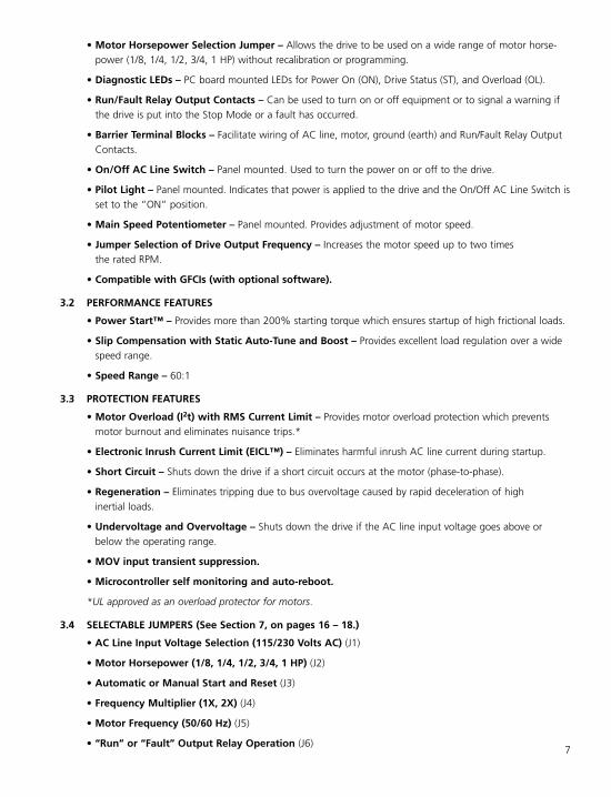
• Motor Horsepower Selection Jumper – Allows the drive to be used on a wide range of motor horse-power (1/8, 1/4, 1/2, 3/4, 1 HP) without recalibration or programming.
• Diagnostic LEDs – PC board mounted LEDs for Power On (ON), Drive Status (ST), and Overload (OL).
• Run/Fault Relay Output Contacts – Can be used to turn on or off equipment or to signal a warning ifthe drive is put into the Stop Mode or a fault has occurred.
• Barrier Terminal Blocks – Facilitate wiring of AC line, motor, ground (earth) and Run/Fault Relay OutputContacts.
• On/Off AC Line Switch – Panel mounted. Used to turn the power on or off to the drive.
• Pilot Light – Panel mounted. Indicates that power is applied to the drive and the On/Off AC Line Switch isset to the “ON” position.
• Main Speed Potentiometer – Panel mounted. Provides adjustment of motor speed.
• Jumper Selection of Drive Output Frequency – Increases the motor speed up to two timesthe rated RPM.
• Compatible with GFCIs (with optional software).
3.2 PERFORMANCE FEATURES
• Power Start™ – Provides more than 200% starting torque which ensures startup of high frictional loads.
• Slip Compensation with Static Auto-Tune and Boost – Provides excellent load regulation over a widespeed range.
• Speed Range – 60:1
3.3 PROTECTION FEATURES
• Motor Overload (I2t) with RMS Current Limit – Provides motor overload protection which preventsmotor burnout and eliminates nuisance trips.*
• Electronic Inrush Current Limit (EICL™) – Eliminates harmful inrush AC line current during startup.
• Short Circuit – Shuts down the drive if a short circuit occurs at the motor (phase-to-phase).
• Regeneration – Eliminates tripping due to bus overvoltage caused by rapid deceleration of highinertial loads.
• Undervoltage and Overvoltage – Shuts down the drive if the AC line input voltage goes above orbelow the operating range.
• MOV input transient suppression.
• Microcontroller self monitoring and auto-reboot.
*UL approved as an overload protector for motors.
3.4 SELECTABLE JUMPERS (See Section 7, on pages 16 – 18.)
• AC Line Input Voltage Selection (115/230 Volts AC) (J1)
• Motor Horsepower (1/8, 1/4, 1/2, 3/4, 1 HP) (J2)
• Automatic or Manual Start and Reset (J3)
• Frequency Multiplier (1X, 2X) (J4)
• Motor Frequency (50/60 Hz) (J5)
• “Run” or “Fault” Output Relay Operation (J6)7

3.5 TRIMPOT ADJUSTMENTS (See Section 11, on pages 21 – 23.)
• Minimum Speed (MIN)
• Maximum Speed (MAX)
• Acceleration (ACCEL)
• Deceleration (DECEL)
• Slip Compensation (COMP)
• Current Limit (CL)
8
Description Part No.
Forward-Stop-Reverse Switch: Provides motor reversing, stop, and manual start functions. 9519
KBRF-300: Panel mount. AC line Class B RFI (EMI) filter which meets the CE Council Directive 89/336/EEC ResidentialRequirement. Installs externally to the drive.
9484
Programming Kit: Includes DownLoad Module™ (DLM) handheld programming device which uploads and downloads
drive programs, PC to DLM serial communication cable, PC to DLM serial and USB communication cables, DLM to drive
communication cable, and PC Windows® based Drive-Link™ communication software. Available for OEM applications
only – contact our Sales Department.
9582
TABLE 1 – OPTIONAL ACCESSORIES
9
Description Specification Factory Setting
115 Volt AC Line Input Voltage Operating Range (Volts AC)1 115 (±15%) —
208/230 Volt AC Line Input Voltage Operating Range (Volts AC)1 208 (-15%) / 230 (+15%) 2 —
Maximum Load (% Current Overload for 1 Minute) 150 —
Horsepower Selection (HP) (J2) 1/8, 1/4, 1/2, 3/4, 1 1
Carrier, Switching Frequency (kHz) 16, 8 —
Output Frequency Resolution (Bits, Hz) 10, .06 —
Minimum Speed Trimpot (MIN) Range (% Frequency Setting) 0 – 40 0
Maximum Speed Trimpot (MAX) Range (% Frequency Setting) 70 – 110 100
Acceleration Trimpot (ACCEL) and Deceleration Trimpot (DECEL) Range (Seconds) .3 – 20 1.5
Slip Compensation Trimpot (COMP) Range at Drive Rating (Volts/Hz) 0 – 3 1.5
Current Limit Trimpot (CL) Range (% Full Load) 40 – 200 160
Motor Frequency Setting (Hz) (Jumper J5) 50, 60 60
Output Frequency Multiplier (1X, 2X) (Jumper J4) 3 1, 2 1
Minimum Operating Frequency at Motor (Hz) 0.3 —
Speed Range (Ratio) 60:1 —
Speed Regulation (30:1 Speed Range, 0 – Full Load) (% Base Speed) 4 2.5 —
Overload Protector Trip Time for Stalled Motor (Seconds) 6 —
Undervoltage/Overvoltage Trip Points for 115 Volt AC Line Input (±5%) (Volts AC)1 76 – 141 —
Undervoltage/Overvoltage Trip Points for 208/230 Volt AC Line Input (±5%) (Volts AC)1 151 – 282 —
Run/Fault Relay Output Contact Rating (Amps at 30 Volts DC, 125 Volts AC, 250 Volts AC) 1, 0.5, 0.25 —
Operating Temperature Range (°C / °F) 0 – 45 / 32 – 113 —
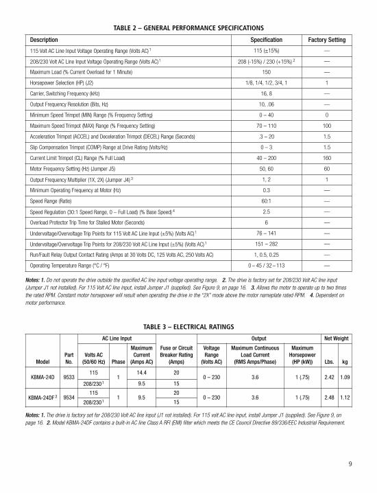
Notes: 1. Do not operate the drive outside the specified AC line input voltage operating range. 2. The drive is factory set for 208/230 Volt AC line input(Jumper J1 not installed). For 115 Volt AC line input, install Jumper J1 (supplied). See Figure 9, on page 16. 3. Allows the motor to operate up to two timesthe rated RPM. Constant motor horsepower will result when operating the drive in the “2X” mode above the motor nameplate rated RPM. 4. Dependent onmotor performance.
TABLE 2 – GENERAL PERFORMANCE SPECIFICATIONS
ModelPartNo.
AC Line Input
Fuse or CircuitBreaker Rating
(Amps)
Output Net Weight
Volts AC(50/60 Hz) Phase
MaximumCurrent(Amps AC)
VoltageRange
(Volts AC)
Maximum ContinuousLoad Current
(RMS Amps/Phase)
MaximumHorsepower(HP (kW)) Lbs. kg
KBMA-24D 9533115
114.4 20
0 – 230 3.6 1 (.75) 2.42 1.09208/2301 9.5 15
KBMA-24DF 2 9534115
1 9.520
0 – 230 3.6 1 (.75) 2.48 1.12208/2301 15
TABLE 3 – ELECTRICAL RATINGS
Notes: 1. The drive is factory set for 208/230 Volt AC line input (J1 not installed). For 115 volt AC line input, install Jumper J1 (supplied). See Figure 9, onpage 16. 2. Model KBMA-24DF contains a built-in AC line Class A RFI (EMI) filter which meets the CE Council Directive 89/336/EEC Industrial Requirement.

10
9.0
0.35
5.080.2
4x ø
4x ø
9.91
0.39
4.30
109
5.10
130
7.00
178
126
4.95
7.6
0.30
27.9
1.10
Stan
dard
3/4"
Fittin
gs
5.10 130
1.45
36.8
44.5
1.75
0.95
24.1
0.95
24.1
1.00
25.4
3.20
2.35
59.7
81.3
105
4.15
Back
view
is sh
own d
imen
sione
d
Side v
iew is
show
n dim
ensio
ned
with
the co
ver in
stalle
d.
Reco
mmen
ded t
ighten
ing to
rque
for t
hetw
o fron
t cov
er sc
rews:
5 in-
lbs (6
kg-c
m).
A mou
nting
temp
late i
s inc
luded
tofac
ilitate
mou
nting
of th
e driv
e.wi
thout
the co
ver in
stalle
d.
"Kno
ckou
ts" fo
r
FIGURE 2 – MECHANICAL SPECIFICATIONS (Inches/mm)

11
Main
Spee
d Pote
ntiom
eter
Front
Cove
r Scre
ws
On/O
ff AC L
ine Sw
itch
Pilot
Light
Prov
ision
for O
ption
alFo
rward
-Stop
-Rev
erse
Switc
hA
C M
OTO
R SP
EED
CO
NTR
OL
KBM
A S
ERIE
S • N
EMA
1 /
IP 5
0
Hyb
rid
Dri
ve™
FIGURE 3 – COVER LAYOUT
12
CON2
: Use
d for
optio
nal F
orwa
rd-S
top-R
ever
se Sw
itch.*
* The
optio
nal F
orward
-Stop
-Rev
erse
Switc
h is r
equir
ed fo
r Man
ual S
tart.
Main
Spee
d Pote
ntiom
eter T
ermi
nals
(P1, P
2, P3
).Ad
justab
le Tri
mpots
(CL,
MAX,
MIN,
ACCE
L, DE
CEL,
COMP
).
J4: 1
X or u
p to 2
X Rate
d Moto
r RPM
Ope
ration
.
J6: "
Run"
or "F
ault"
Outp
ut Re
lay.
J3: A
utoma
tic or
Man
ual S
tart a
nd Re
set O
perat
ion.*
TB1:
AC Li
ne In
put, M
otor, G
round
, and
conn
ectio
ns. S
ee Fi
gure
7, on
page
15.
J5: 6
0 Hz o
r 50 H
z Moto
r Ope
ration
.
TB2:
Run/F
ault R
elay O
utput
Conta
cts.
J2: M
otor H
orse
powe
r.
Jump
ers an
d trim
pots
are sh
own i
n fac
tory s
et po
sition
s.
CON1
: Use
d to c
onne
ct op
tiona
l acc
esso
ries t
o the
drive
.
Instal
l jump
er fo
r 115
Volt A
C line
inpu
t. See
Figu
re 9,
on pa
ge 16
.J1
: AC L
ine In
put V
oltag
e sele
ction
.
Diagn
ostic
LEDs
(Pow
er O
n, St
atus,
Over
load).
Main
Spee
d Pote
ntiom
eter
(Fron
t View
)
Pane
l Mou
nted
Violet
Oran
ge
White
Pilot
Lamp
Pane
l Mou
nted
On/O
ff AC L
ine Sw
itch
(Back
View
)
Pane
l Mou
nted
Black Blu
e
Blue
Black
White
White
L1B
L1A
L2A
L2B
CON1
115VAC
J1
J1-A
AB
J1-B
UGN
DV
WL1
L2TB
1
MOTO
RAC
LINE
N.O.
COM
N.C.
TB2
OLONST F RS
CON2
P 1P 2P 3
J6FL
T
RUN
FREQ
50HZ
60HZ
J5J3 J21/2 1/81/43/41H
P
MULT
AUTO
1XJ4
2XMAN
ACCEL
C M PE C C OD
COMPDECEL
N CAIMM XAC L
MINMAXCL
FIGURE 4 – DRIVE LAYOUT

4 IMPORTANT APPLICATION INFORMATION4.1 MOTOR WITH EXTERNAL FAN
COOLING – Most totally enclosed fan-cooled (TEFC) and open ventilated 3-phaseAC induction motors will overheat if usedbeyond a limited speed range at fulltorque. Therefore, it is necessary to reducemotor load as speed is decreased.
Note: Some fan-cooled motors can beused over a wider speed range. Consult themotor manufacturer for details.
WARNING! Some motors have lowspeed characteristics which cause
overheating and winding failure under lightload or no load conditions. If the motor isoperated in this manner for an extendedperiod of time, it is recommended that theunloaded motor current be checked from2 – 15 Hz (60 – 450 RPM) to ensure motorcurrent does not exceed the nameplaterating. Do not use motor if the motorcurrent exceeds the nameplate rating.
It is recommended that the drivebe used with Inverter Duty or
TENV motors.
Inverter duty and most totally enclosed non-ventilated (TENV) motors can provide full rated torque over anextended speed range without overheating. See Figure 5.
If external fan cooling is provided, open ventilated motors can also achieve an extended speed range at fullrated torque. A box fan or blower with a minimum of 100 CFM per HP is recommended. Mount the fan orblower so the motor is surrounded by the airflow. See Figure 6.
4.2 ELECTRONIC MOTOR OVERLOAD PROTECTION – The drive contains Modified I2t Overload Protection.*Part of this function consists of a Current Limit (CL) circuit, which limits the drive current to a factory presetlevel of 160% of the rated drive current. The CL Trimpot is used to recalibrate the drive current from 60%thru 200%. The Power Start™ circuit provides an overshoot function that allows most motors to developmore than 200% of starting torque and breakdown torque.
Standard I2t is undesirable because it causes nuisance tripping. It allows a very high motor current todevelop and will turn the drive off after a short period of time. KB’s RMS Current Limit Circuit avoids thisnuisance tripping while providing maximum motor protection.
If the motor is overloaded to 120% of full load (75% of the CL setting), the I2t Timer starts. If the motor con-tinues to be overloaded at the 120% level, the timer will shut down the drive after 30 minutes. If the motor isoverloaded to 160% of full load, the drive will trip in 6 seconds. See Section 11.6, on pages 22 and 23.
*UL approved as an overload protector for motors. 13
FIGURE 5 – MAXIMUM ALLOWED MOTOR TORQUE VS. SPEED
FIGURE 6 – OPEN VENTILATED MOTOR WITH EXTERNAL FAN COOLING
Motorsand TENV
Inverter Duty
Maxim
um Al
lowed
Motor
Torqu
e (%)
TEFC and Open VentilatedMotors
Fan Cooled
10060 70 805030 40100 20 90
Motor Speed (%)
40
0
20
60
80
100
Open Ventilated MotorFan or Blower(100 CFM Min.
per HP)
Airflow

5 MOUNTING INSTRUCTIONSThe drive is designed with a NEMA-1 / IP-40 enclosure for indoor use. It is recommended that the drive bemounted vertically on a flat surface with adequate ventilation. Leave enough room below the drive to allow for ACline, motor connections, and any other wiring that is required. Care should be taken to avoid extreme hazardouslocations where physical damage can occur. When mounting the drive in an enclosure, the enclosure should belarge enough to allow for proper heat dissipation so that the ambient temperature does not exceed 45°C (113 °F)at full rating. See Figure 2, on page 10. A mounting template is included to facilitate mounting of the drive.
WARNING! Do not use this drive in an explosion-proof application.
6 ELECTRICAL CONNECTIONSSee Table 4, for terminal block wire and tightening torque specifications.
WARNING! Read Safety Warning, on page 5, before using the drive. Disconnect main powerbefore making connections to the drive. To avoid electric shock, be sure to
properly ground the drive.
Application Note: To avoid erratic operation, do not bundle the AC line and motor wires with eachother or with wires from signal following, start/stop contacts, or any other signal wires. Also, do notbundle motor wires from multiple drives in the same conduit. Use shielded cables on all signal wiringover 12” (30 cm). The shield should be earth grounded on the drive side only. Connect the drive inaccordance with the National Electrical Code requirements and other local codes that may apply.
Be sure to properly fuse each AC line conductor that is not at ground potential. Do not fuse neutral orgrounded conductors. A separate AC line switch or contactor must be installed as a disconnect so thateach ungrounded conductor is opened. For fuse or circuit breaker rating, see Table 3, on page 9. Alsosee Section 6.1, below and on page 15.
The drive is designed with a removable cover. To open the cover, the two front cover screws must beremoved. After mounting and connections, install and tighten the two front cover screws to5 in-lbs (6 kg-cm). Do not overtighten.
6.1 AC LINE INPUT CONNECTION – Connect the single-phase AC line input to Terminal Block TB1 (Terminals“L1”, “L2”), as shown in Figure 7, on page 15.
The rated AC line voltage of the drive must match the actual AC line input voltage setting ofJumper J1. The drive is factory set for 208/230 Volt AC line input (Jumper J1 not installed). For 115Volt AC line input, install Jumper J1 (supplied). See Section 7.1, on page 16.
14
Terminal Block Description
Maximum Wire Size (Cu) Recommended Tightening Torque
AWG mm2 in-lbs kg-cm
TB1 AC Line Input and Motor Wiring 12 3.3 7 8
TB2 Run/Fault Relay Output Contacts 16 1.3 3.5 3
TABLE 4 – TERMINAL BLOCK WIRE & TIGHTENING TORQUE SPECIFICATIONS

GFCI Operation – Do not connect thisdrive to an AC power source controlledby a Ground-Fault Circuit-Interrupter.Special software is available for GFCIoperation – contact our SalesDepartment.
AC Line Fusing – The drive does not containline fuses. Most electrical codes require thateach ungrounded conductor contain circuitprotection. Do not fuse neutral or groundconnections. It is recommended to install afuse (Littelfuse 326, Buss ABC, or equivalent)or a circuit breaker in series with eachungrounded conductor. Connect the drive inaccordance with the National Electrical Coderequirements and other local codes that mayapply to the application. Do not fuse motorleads. For the recommended fuse size, see Table 3, on page 9.
6.2 GROUND CONNECTION – Connect the ground (earth) wires from the AC line and motor to Terminal BlockTB1 (Terminal “GND”). See Figure 7.
6.3 MOTOR CONNECTION – Connect the motor to Terminal Block TB1 Terminals “U”, “V”, “W”. See Figure 7.Motor cable length should not exceed 100 ft (30 m) – special reactors may be required – consult our SalesDepartment. Be sure Jumper J2 is set to the corresponding motor horsepower rating, as described in Section7.2, on page 16.
Note: If the motor rotates in the incorrect direction, it will be necessary to disconnect the AC line andchange the position of the jumper on CON2 from “F” to “R” or reverse any two motor leads.
6.4 RUN/FAULT RELAY CONNECTION – The Run/Fault RelayOutput Contacts are located at TB2 and can be used toturn on or off equipment or to signal a warning if a faulthas occurred or the drive is put into the Stop Mode*. SeeFigure 8. The Run/Fault Relay Contact status forvarious drive operating conditions is shown in Table 5, onpage 16. Also see Section 7.5, on page 18.
Relay Contacts Ratings – 1 Amp at 30 Volts DC, 0.5Amps at 125 Volts AC, and 0.25 Amps at 250Volts AC.
*In order for the Run/Fault Relay to give “Stop Mode” indication, the optional Forward-Stop Reverse Switch(Part No. 9519) must be installed.
15
FIGURE 7 – AC LINE INPUT, MOTOR & GROUND CONNECTIONS
115* or 208/230 VoltSingle-Phase AC Line Input
3-Phase, 208/230 VoltAC Induction Motor
AC LINEMOTOR
Motor
TB1 U V
Ground (Earth)
GNDW L1 L2
* For 115 VAC line, install Jumper J1 (supplied).
FIGURE 8 – RUN/FAULT RELAYOUTPUT CONTACTS CONNECTIONS
Normally Open
Normally Closed
Relay CommonRun/Fault RelayOutput Contacts
TB2
COMN.C. N.O.

16
7.2 MOTOR HORSEPOWER (J2) – Set Jumper J2 to the corresponding positionfor the motor being used. See Figure 10.
7.3 AUTOMATIC OR MANUAL START AND RESET SELECTION (J3) –See Figure 11, on page 17.
7.3.1 WARNING! Automatic Start and Reset – Jumper J3 is factory setto the “AUTO” position to automatically start the drive when thepower is applied and the On/Off AC Line Switch is set to the“ON” position. The drive will also automatically restart after anUndervoltage or Overvoltage Fault has cleared.
DriveOperatingCondition Description
Run Relay Operation(J5 Installed in “RUN” Position)
(Factory Setting)Fault Relay Operation
(J5 Installed in “FLT” Position)
Normally OpenContact
Normally ClosedContact
Normally OpenContact
Normally ClosedContact
Power Off Main Power Disconnected Open Closed Open Closed
Run Mode1 Normal Drive Operation Closed Open Closed Open
Stop Mode2 Selected by Operator Open Closed Closed Open
Fault3 Drive Tripped Open Closed Open Closed
TABLE 5 – DRIVE OPERATING CONDITIONS & RUN/FAULT RELAY CONTACT STATUS
Notes: 1. Run Mode is selected with the optional Forward-Stop-Reverse Switch or with the jumper installed in CON2 (jumper installed in the “F-S” position for forward direction (factory setting) or jumper installed in the “R-S” position for reverse direction). 2. Stop Mode is selected usingthe optional Forward-Stop-Reverse Switch. 3. I 2t, Short Circuit, Undervoltage, Overvoltage.
7 SETTING SELECTABLE JUMPERSThe drive has customer selectable jumpers which must be set before the drive can be used. For the location ofjumpers, see Figure 4, on page 12. Disconnect the AC line before changing position of Jumpers.
7.1 AC LINE INPUT VOLTAGE (J1) – The drive is factory set for 208/230 Volt AC line input(Jumper J1 notinstalled). For 115 Volt AC line input, install Jumper J1. See Figure 9.
208/230 Volt AC Line Input(Jumper J1 not Installed (Factory Setting))
115 Volt AC Line InputJumper J1 Installed2
115V
AC
J1A
J1-A
B
J1-B
115V
AC
J1
J1-A
A
J1-B
B
Notes: 1. The drive is factory set for 208/230 Volt AC line input (Jumper J1 not installed). For 115 Volt AC line input, install JumperJ1 (supplied). 2. Jumper J1 is supplied in the hardware bag.
FIGURE 9 – AC LINE INPUT VOLTAGE SELECTION1
FIGURE 10 – MOTORHORSEPOWER SELECTION
J23/4
1/41/8
1/2
1HP
17
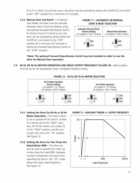
If an I2t or Short Circuit Fault occurs, the drive must be restarted by setting the On/Off AC Line Switchto the “OFF” position for a minimum of 5 seconds.
7.3.2 Manual Start and Reset* – In ManualStart Mode, the drive must be manuallyrestarted, after a fault has cleared, usingthe optional Forward-Stop-Reverse Switch.If a Short Circuit or I2t Fault occurs, thedrive can be restarted by setting either theOn/Off AC Line Switch to the “OFF”position for a minimum of 5 seconds orsetting the Forward-Stop-Reverse Switch tothe “STOP” position.
*Note: The optional Forward-Stop-Reverse Switch must be installed in order to use thedrive for Manual Start operation.
7.4 60 Hz OR 50 Hz MOTOR OPERATION AND DRIVE OUTPUT FREQUENCY (J4 AND J5) – Both jumpersmust be set for the appropriate motor nameplate frequency rating.
7.4.1 Setting the Drive for 60 Hz or 50 HzMotor Operation – The drive is facto-ry set to operate 60 Hz motors. JumperJ5 is factory set to the “60Hz” posi-tion. For 50 Hz motors, set Jumper J5to the “50Hz” position, and be sureJumper J4 is set to the “1X” position.See Figure 12.
7.4.2 Setting the Drive for Two Times theRated Motor RPM – The drive canalso be used to operate the motor upto two times the rated RPM. However,constant horsepower will result whenoperating the drive in the “2X” modeabove the motor rated frequency.See Figure 13.
Automatic Start and Reset(Factory Setting)
(J3 Installed in “AUTO” Position)Manual Start and Reset
(J3 Installed in “MAN” Position)
AUTO
MANJ3
AUTO
MANJ3
FIGURE 11 – AUTOMATIC OR MANUALSTART & RESET SELECTION
60 Hz Motor Operation(Factory Setting)
(J4 Installed in “1X” Position)(J5 Installed in “60Hz” Position)
50 Hz Motor Operation(J4 Installed in “1X” Position)(J5 Installed in “50Hz” Position)
1X
2XMULTJ4
60HZFREQ50HZ
J51X
2XMULTJ4
60HZFREQ50HZ
J5
FIGURE 12 – 60 Hz OR 50 Hz MOTOR SELECTION
FIGURE 13 – AVAILABLE TORQUE VS. OUTPUT FREQUENCY
50/60
Output Frequency (Hz)
020
% To
rque
50
100/120
100

18
7.5 RUN/FAULT OUTPUT RELAYOPERATION (J6) – Jumper J6 is factory set tothe “RUN” position for “Run” operation of theRun/Fault Relay. For “Fault” operation of theRun/Fault Relay, set Jumper J6 to the “FLT”position. See Figure 15.
8 RECOMMENDED HIGH VOLTAGEDIELECTRIC WITHSTAND TESTING(HI-POT TESTING)Testing agencies such as UL, CSA, VDE, etc., usuallyrequire that equipment undergo a hi-pot test. In order to prevent catastrophic damage to the drive which hasbeen installed in the equipment, the following procedure is recommended. A typical hi-pot test setup is shownin Figure 16, on page 19. All drives have been factory hi-pot tested in accordance with UL requirements.
WARNING! All equipment AC line inputs must be disconnected from the AC power.
8.1 Connect all equipment AC power input lines together and connect them to the H.V. lead of the hi-pottester. Connect the RETURN lead of the hi-pot tester to the frame on which the drive and other auxiliaryequipment are mounted.
8.2 The hi-pot tester must have an automatic ramp-up to the test voltage and an automatic ramp-down tozero voltage.
Note: If the hi-pot tester does not have automatic ramping, then the hi-pot output must be manuallyincreased to the test voltage and then manually reduced to zero. This procedure must be followed for eachmachine to be tested. A suggested hi-pot tester is Slaughter Model 2550.
CAUTION! Instantly applying the hi-pot voltage will cause irreversible damage to the drive, which willvoid the warranty.z
120 Hz Output with 60 Hz Motor(J4 Installed in “2X” Position)(J5 Installed in “60Hz” Position)
100 Hz Output with 60 Hz Motor(J4 Installed in “2X” Position)(J5 Installed in “50Hz” Position)
1X
2XMULTJ4
60HZFREQ50HZ
J51X
2XMULTJ4
60HZFREQ50HZ
J5
FIGURE 14 – 120 Hz AND 100 Hz DRIVE OUTPUT FREQUENCY SELECTION
For 120 Hz output with 60 Hz motor, set Jumper J4 to the “2X” position and be sure Jumper J5 is setto the “60Hz” position. For 100 Hz output with 50 Hz motor, set Jumper J4 to the “2X” position andset Jumper J5 to the “50Hz” position. See Figure 14.
“Run” Output Relay Operation(Factory Setting)
(J6 Installed in “RUN” Position)“Fault” Output Relay Operation(J6 Installed in “FLT” Position)
FLTJ6
RUN
FLTJ6
RUN
FIGURE 15 – “RUN” OR “FAULT” OUTPUT RELAYOPERATION SELECTION

19
Run/F
ault R
elay
Auxil
iary E
quipm
ent
Chas
sis
Conn
ect H
i-Pot
toAC
Line
Inpu
ts(M
ain Po
wer D
iscon
necte
d)L2L1
Frame
Equip
ment
Frame
Mach
ine or
(Term
inal B
lock T
B2)
Outpu
t Con
tacts
AC Li
ne In
put
H. V
.RE
SET
ZERO
MAX
RETU
RNTE
STVO
LTAG
E
High V
oltag
e Diel
ectri
c With
stand
Teste
r
30
LEAK
AGE 10
mA
0mA
AC K
ILOV
OLTS
12
(Exce
pt Te
rmina
l "GN
D")
L2L1
WU
VGN
DTB
1
Motor
Wire
s
(Main
Powe
r Disc
onne
cted)
MOTO
R
Do N
ot Hi-
Pot
COM
N.C.
AC LI
NEN.
O.
Secti
onal
View
of KB
MA PC
Board
Conn
ect T
B1 Te
rmina
ls"U
", "V
", "W
", "L
1", "
L2" T
ogeth
erTB
2
FIGURE 16 – TYPICAL HI-POT TEST SETUP

20
WARNING! The motor will run at the Main Speed Potentiometer setting when the AC lineis applied.
To start the drive, set the On/Off AC Line Switch to the “ON” position. If the AC power has beenproperly brought to the drive, the Pilot Light will illuminate. If the optional Forward-Stop-Reverse Switch hasbeen installed, set it to the “FWD” or “REV” position. The motor will begin to accelerate to the set speed.The PC board mounted “ST” and “OL” LEDs will indicate the drive status, as described in Sections 10.3 and10.4, on page 21.
Note: If the motor rotates in the incorrect direction, it will be necessary to disconnect the AC line andchange the position of the jumper on CON2 from “F” to “R” or reverse any two motor leads, and repeatthe start-up procedure.
9.2 RESTARTING THE DRIVE AFTER A FAULT HAS BEEN CLEARED – The drive monitors four faults(Undervoltage, Overvoltage, Short Circuit (at the motor (phase-to-phase)), and Overload). The PC boardmounted “ST” and “OL” LEDs will indicate the drive status, as described in Sections 10.3 and 10.4, on page21. Also see Section 7.3, on pages 16 and 17, for Automatic or Manual Start and Reset selectionwith Jumper J3.
9.2.1 WARNING! Drive Set for Automatic Start and Reset (Factory Setting) – The drive will automatically restart after an Undervoltage or Overvoltage Fault has cleared (J3 set to the
“AUTO” position). For an I2t Fault, be sure the fault has been cleared before restarting the drive.Check the motor current with an AC RMS responding ammeter. Also, the CL setting may be set toolow. See Section 11.6, on pages 22 and 23. For an I2t or Short Circuit Fault, the drive must be restart-ed by setting the On/Off AC Line Switch to the “OFF” position for a minimum of 5 seconds.
9.2.2 Drive Set for Manual Start and Reset* – In Manual Start Mode, the drive must be manuallyrestarted, after a fault has cleared, using the optional Forward-Stop-Reverse Switch. If a Short Circuitor I2t Fault occurs, the drive can be restarted by setting either the On/Off AC Line Switch to the“OFF” position for a minimum of 5 seconds or setting the Forward-Stop-Reverse Switch to the“STOP” position.
*Note: The optional Forward-Stop-Reverse Switch must be installed in order to use the drive forManual Start operation.
10 PILOT LIGHT AND DIAGNOSTIC LEDs
WARNING! Do not depend on the Pilot Light or the PC board mounted LEDs to no longer beilluminated as a guaranteed power off condition. Be sure the main power switch or circuit breaker
is in the “OFF” position before servicing the drive.
Note: This drive contains bus capacitors which must be reconditioned if the drive has been in storage forover 1 year. To recondition the bus capacitors, apply the AC line, with the main speed potentiometer setto zero, for a minimum of 30 minutes.
9 DRIVE OPERATION9.1 START-UP PROCEDURE – After the drive has been properly setup (jumpers and trimpots set to the desired
positions) and wiring completed, the start-up procedure can begin.

21
11 TRIMPOT ADJUSTMENTSThe drive contains trimpots which are factory set for most applications. See Figure 4, on page 12, for the locationof the trimpots and their approximate factory calibrated positions. Some applications may require readjustmentof the trimpots in order to set the drive for a specific requirement. The trimpots may be readjusted as describedbelow.
WARNING! If possible, do not adjust trimpots with the mainpower applied. If adjustments are made with the main power
applied, an insulated adjustment tool must be used and safety glassesmust be worn. High voltage exists in this drive. Fire and/or electrocutioncan result if caution is not exercised. Safety Warning, on page 5, must beread and understood before proceeding.
11.1 MINIMUM SPEED (MIN) – Sets the minimum speed of the motor. The MINTrimpot is factory set to 0% of frequency setting. For a higher minimumspeed, setting, rotate the MIN Trimpot clockwise. See Figure 17.
10.1 PILOT LIGHT – Located on the front cover. The Pilot Light will illuminate orange when the AC line is appliedto the drive and the On/Off AC Line Switch is set to the “ON” position.
10.2 POWER ON LED (ON) – Located on the PC board. The “ON” LED will illuminate green when the AC line isapplied to the drive and the On/Off AC Line Switch is set to the “ON” position.
10.3 STATUS LED (ST) – Located on the PC board. The “ST” LED is a green LED, which providesindication of a fault or abnormal condition. The information provided can be used to diagnose an installa-tion problem such as incorrect input voltage and drive output miswiring. It also provides asignal which informs the user that all drive and microcontroller operating parameters are normal.Table 6 summarizes the “ST” LED functions.
10.4 OVERLOAD LED (OL) – Located on the PC board. The “OL” LED is a red LED, which providesindication of an overload condition. Table 6, summarizes the “OL” LED functions.
Drive Operating Condition
LED and Flash Rate1 Information
ST (Green) OL (Red)
Normal operation Slow Flash Off
Overload (120% – 160% Full Load) Off On2
I2t (Drive Timed Out) Off Quick Flash
Short Circuit Off Slow Flash
Undervoltage Quick Flash3 On
Overvoltage Slow Flash3 On
Stop On On
TABLE 6 – DRIVE OPERATING CONDITIONS & LED INDICATIONS
Notes: 1. Slow Flash = 1 second on and 1 second off. Quick Flash = 0.25 second on and 0.25 second off. 2. When the Overload is removed,before the I 2t times out and trips the drive, the “ST” LED will flash green and the “OL” LED will turn off. 3. In Manual Restart Mode, when theUndervoltage or Overvoltage condition is cleared, the “ST” and “OL” LEDs will flash red / (red and green) / green.
MIN30
15 0
35 40
FIGURE 17 – MINIMUM SPEEDTRIMPOT RANGE
(Shown Factory Set to 0%Frequency Setting)

11.2 MAXIMUM SPEED (MAX) – Sets the maximum speed of the motor. TheMAX Trimpot is factory set for 100% of frequency setting. For a lower maxi-mum speed setting, rotate the MAX Trimpot counterclockwise. For a highermaximum speed setting, rotate the MAX Trimpot clockwise. See Figure 18.
11.3 ACCELERATION (ACCEL) – Sets the amount of time for the motor to accel-erate from zero speed to full speed. The ACCEL Trimpot is factoryset to 1.5 seconds. For a longer acceleration time, rotate the ACCEL Trimpotclockwise. For more rapid acceleration, rotate the ACCEL Trimpot counter-clockwise. See Figure 19.
Note: Rapid acceleration settings may cause the current limit circuit toactivate, which will extend the acceleration time.
11.4 DECELERATION (DECEL) – Sets the amount of time for the motor to decel-erate from full speed to zero speed. The DECEL Trimpot is factoryset to 1.5 seconds. For longer deceleration time, rotate the DECEL Trimpotclockwise. For more rapid deceleration, rotate the DECEL Trimpot counter-clockwise. See Figure 20.
Application Note – On applications with high inertial loads, the decelera-tion may automatically increase in time. This will slow down the rate ofspeed of decrease to prevent the bus voltage from rising to the OvervoltageTrip point. This function is called Regeneration Protection. It is recommendedthat for very high inertial loads that both the ACCEL and DECEL Trimpots beset to greater than 10 seconds.
11.5 SLIP COMPENSATION (COMP) – Sets the amount of Volts/Hz to maintainset motor speed under varying loads. The COMP Trimpot is factory set to 1.5Volts/Hz, which provides excellent speed regulation for most motors.To increase the slip compensation, rotate the COMP Trimpot clockwise.To decrease the slip compensation, rotate the COMP Trimpot counterclock-wise. See Figure 21.
The slip compensation may be adjusted as follows:
1. Connect an AC RMS ammeter in series with onemotor phase.
2. Run the motor and set the unloaded speed to approximately 50%(900 RPM on 4-pole 1500/1725 RPM motors).
3. Using a tachometer, record the unloaded speed.
4. Load the motor to the nameplate rated current (AC Amps).
5. Adjust the COMP Trimpot until the loaded RPM is equal to theunloaded RPM.
The motor is now compensated to provide constant speed under varying loads.
11.6 MOTOR OVERLOAD (I2t) WITH RMS CURRENT LIMIT (CL)* – Sets the current limit (overload), whichlimits the maximum current to the motor, preventing motor burnout and eliminating nuisance trips.
22
11010090
75 70
80 MAX
FIGURE 18 – MAXIMUM SPEEDTRIMPOT RANGE
(Shown Factory Set to 100%of Frequency Setting)
ACCE
L
3 1.5 0.3
10
17 20
FIGURE 19 – ACCELERATIONTRIMPOT RANGE
(Shown Factory Set to 1.5 Seconds)
DECE
L
3 1.5
10
0.3
17 20
FIGURE 20 – DECELERATIONTRIMPOT RANGE
(Shown Factory Set to 1.5 Seconds)
COMP1.5
0.8 0
2.3 3
FIGURE 21 – SLIP COMPENSATIONTRIMPOT RANGE
(Shown Factory Set to 1.5 Volts/Hz)

23
The CL Trimpot is factory set to 160% of the drive rated current. Toincrease the current limit, rotate the CL Trimpot clockwise. To decrease thecurrent limit, rotate the CL Trimpot counterclockwise. See Figure 22.
Figure 23 shows the I2t Trip Time vs. Motor Overload. Also see Section4.2, on page 13.
*UL approved as an electronic overload protector for motors.
CAUTION! Adjusting the current limit above 160% of the motornameplate rating can cause overheating of the motor. Consult the motormanufacturer. Do not leave the motor in a locked rotor condition for more than a few seconds sincedamage may occur.
In order to ensure that the motor is properly protected with the I2t feature, it is required that theCL Trimpot be set for 160% of the motor nameplate rated current, as described on page 16.
Note: This adjustment must be made within 6 seconds or an I2t Trip will occur.
The current limit may be adjusted as follows:
1. Connect an AC RMS ammeter in series with one motor phase.
2. Set the CL Trimpot fully counterclockwise.
3. Adjust the speed setting to 30%.
4. Lock the motor shaft and adjust the CL Trimpot to 160% of the motor nameplate rated current.
CL120
80 40
160 200
FIGURE 22 – CURRENT LIMITTRIMPOT RANGE
(Shown Factory Set to 160% Full Load)
Trip T
ime (
Minu
tes)
CL (Factory Setting)
140110 120 1300.1
Motor Current (%)
1
160150
10
100
1000
FIGURE 23 – I2t TRIP TIME VS. MOTOR CURRENT

LIMITED WARRANTYFor a period of 18 months from the date of original purchase, KB Electronics, Inc. will repair or replace withoutcharge, devices which our examination proves to be defective in material or workmanship. This warranty is valid ifthe unit has not been tampered with by unauthorized persons, misused, abused, or improperly installed and hasbeen used in accordance with the instructions and/or ratings supplied. The foregoing is in lieu of any otherwarranty or guarantee, expressed or implied. KB Electronics, Inc. is not responsible for any expense, includinginstallation and removal, inconvenience, or consequential damage, including injury to any person, caused by itemsof our manufacture or sale. Some states do not allow certain exclusions or limitations found in this warranty andtherefore they may not apply to you. In any event, the total liability of KB Electronics, Inc., under anycircumstance, shall not exceed the full purchase price of this product. (rev 2/2000)
COPYRIGHT © 2011 KB Electronics, Inc.All rights reserved. In accordance with the United States Copyright Act of 1976, no part of this publication maybe reproduced in any form or by any means without permission in writing from KB Electronics, Inc. (8/2002)
KB ELECTRONICS, INC.12095 NW 39th Street, Coral Springs, FL 33065-2516 • (954) 346-4900 • FAX (954) 346-3377Outside Florida Call Toll Free (800) 221-6570 • [email protected]
(A40153) – Rev. C – 05/2015FG – 3K – 05/2015


