Install Connect Router Cisco
44
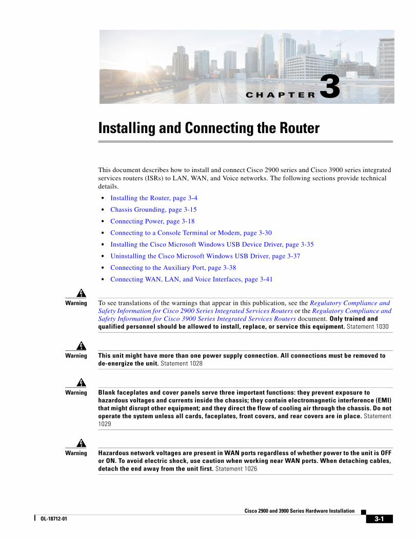
CHAPTER 3-1 Cisco 2900 and 3900 Series Hardware Installation OL-18712-01 3 Installing and Connecting the Router This document describes how to install and connect Cisco 2900 series and Cisco 3900 series integrated services routers (ISRs) to LAN, WAN, and Voice networks. The following sections provide technical details. • Installing the Router, page 3-4 • Chassis Grounding, page 3-15 • Connecting Power, page 3-18 • Connecting to a Console Terminal or Modem, page 3-30 • Installing the Cisco Microsoft Windows USB Device Driver, page 3-35 • Uninstalling the Cisco Microsoft Windows USB Driver, page 3-37 • Connecting to the Auxiliary Port, page 3-38 • Connecting WAN, LAN, and Voice Interfaces, page 3-41 Warning To see translations of the warnings that appear in this publication, see the Regulatory Compliance and Safety Information for Cisco 2900 Series Integrated Services Routers or the Regulatory Compliance and Safety Information for Cisco 3900 Series Integrated Services Routers document. Only trained and qualified personnel should be allowed to install, replace, or service this equipment. Statement 1030 Warning This unit might have more than one power supply connection. All connections must be removed to de-energize the unit. Statement 1028 Warning Blank faceplates and cover panels serve three important functions: they prevent exposure to hazardous voltages and currents inside the chassis; they contain electromagnetic interference (EMI) that might disrupt other equipment; and they direct the flow of cooling air through the chassis. Do not operate the system unless all cards, faceplates, front covers, and rear covers are in place. Statement 1029 Warning Hazardous network voltages are present in WAN ports regardless of whether power to the unit is OFF or ON. To avoid electric shock, use caution when working near WAN ports. When detaching cables, detach the end away from the unit first. Statement 1026
-
Upload
juragan-kemod -
Category
Documents
-
view
255 -
download
1
Transcript of Install Connect Router Cisco
OL-18712-01
C H A P T E R 3
Installing and Connecting the RouterThis document describes how to install and connect Cisco 2900 series and Cisco 3900 series integrated services routers (ISRs) to LAN, WAN, and Voice networks. The following sections provide technical details.
• Installing the Router, page 3-4
• Chassis Grounding, page 3-15
• Connecting Power, page 3-18
• Connecting to a Console Terminal or Modem, page 3-30
• Installing the Cisco Microsoft Windows USB Device Driver, page 3-35
• Uninstalling the Cisco Microsoft Windows USB Driver, page 3-37
• Connecting to the Auxiliary Port, page 3-38
• Connecting WAN, LAN, and Voice Interfaces, page 3-41
Warning To see translations of the warnings that appear in this publication, see the Regulatory Compliance and Safety Information for Cisco 2900 Series Integrated Services Routers or the Regulatory Compliance and Safety Information for Cisco 3900 Series Integrated Services Routers document. Only trained and qualified personnel should be allowed to install, replace, or service this equipment. Statement 1030
Warning This unit might have more than one power supply connection. All connections must be removed to de-energize the unit. Statement 1028
Warning Blank faceplates and cover panels serve three important functions: they prevent exposure to hazardous voltages and currents inside the chassis; they contain electromagnetic interference (EMI) that might disrupt other equipment; and they direct the flow of cooling air through the chassis. Do not operate the system unless all cards, faceplates, front covers, and rear covers are in place. Statement 1029
Warning Hazardous network voltages are present in WAN ports regardless of whether power to the unit is OFF or ON. To avoid electric shock, use caution when working near WAN ports. When detaching cables, detach the end away from the unit first. Statement 1026
3-1Cisco 2900 and 3900 Series Hardware Installation

Chapter 3 Installing and Connecting the Router
Warning This equipment must be grounded. Never defeat the ground conductor or operate the equipment in the absence of a suitably installed ground conductor. Contact the appropriate electrical inspection authority or an electrician if you are uncertain that suitable grounding is available. Statement 1024
Warning Before opening the unit, disconnect the telephone-network cables to avoid contact with telephone-network voltages. Statement 1041
Warning Do not use this product near water; for example, near a bath tub, wash bowl, kitchen sink or laundry tub, in a wet basement, or near a swimming pool. Statement 1035
Warning Never install telephone jacks in wet locations unless the jack is specifically designed for wet locations. Statement 1036
Warning Never touch uninsulated telephone wires or terminals unless the telephone line has been disconnected at the network interface. Statement 1037
Warning Avoid using a telephone (other than a cordless type) during an electrical storm. There may be a remote risk of electric shock from lightning. Statement 1038
Warning To report a gas leak, do not use a telephone in the vicinity of the leak. Statement 1039
Warning This unit is intended for installation in restricted access areas. A restricted access area can be accessed only through the use of a special tool, lock and key, or other means of security. Statement 1017
Warning Blank faceplates and cover panels serve three important functions: they prevent exposure to hazardous voltages and currents inside the chassis; they contain electromagnetic interference (EMI) that might disrupt other equipment; and they direct the flow of cooling air through the chassis. Do not operate the system unless all cards, faceplates, front covers, and rear covers are in place. Statement 1029
Warning The covers are an integral part of the safety design of the product. Do not operate the unit without the covers installed. Statement 1077
3-2Cisco 2900 and 3900 Series Hardware Installation
OL-18712-01
Chapter 3 Installing and Connecting the Router What you Need to Know
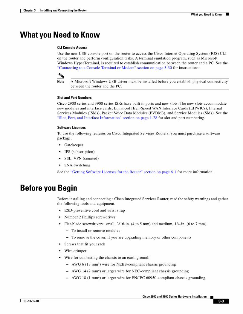
What you Need to KnowCLI Console Access
Use the new USB console port on the router to access the Cisco Internet Operating System (IOS) CLI on the router and perform configuration tasks. A terminal emulation program, such as Microsoft Windows HyperTerminal, is required to establish communication between the router and a PC. See the “Connecting to a Console Terminal or Modem” section on page 3-30 for instructions.
Note A Microsoft Windows USB driver must be installed before you establish physical connectivity between the router and the PC.
Slot and Port Numbers
Cisco 2900 series and 3900 series ISRs have built in ports and new slots. The new slots accommodate new modules and interface cards; Enhanced High-Speed WAN Interface Cards (EHWICs), Internal Services Modules (ISMs), Packet Voice Data Modules (PVDM3), and Service Modules (SMs). See the “Slot, Port, and Interface Information” section on page 1-28 for slot and port numbering.
Software Licenses
To use the following features on Cisco Integrated Services Routers, you must purchase a software package.
• Gatekeeper
• IPS (subscription)
• SSL_VPN (counted)
• SNA Switching
See the “Getting Software Licenses for the Router” section on page 6-1 for more information.
Before you BeginBefore installing and connecting a Cisco Integrated Services Router, read the safety warnings and gather the following tools and equipment.
• ESD-preventive cord and wrist strap
• Number 2 Phillips screwdriver
• Flat-blade screwdrivers: small, 3/16-in. (4 to 5 mm) and medium, 1/4-in. (6 to 7 mm)
– To install or remove modules
– To remove the cover, if you are upgrading memory or other components
• Screws that fit your rack
• Wire crimper
• Wire for connecting the chassis to an earth ground:
– AWG 6 (13 mm2) wire for NEBS-compliant chassis grounding
– AWG 14 (2 mm2) or larger wire for NEC-compliant chassis grounding
– AWG 18 (1 mm2) or larger wire for EN/IEC 60950-compliant chassis grounding
3-3Cisco 2900 and 3900 Series Hardware Installation
OL-18712-01

Chapter 3 Installing and Connecting the Router Unpacking the Router
• For NEC-compliant grounding, an appropriate user-supplied ring terminal, with an inner diameter of 1/4 in. (5 to 7 mm)
In addition, depending on the type of modules you plan to use, you might need the following equipment to connect a port to an external network:
• Cables for connection to the WAN and LAN ports (dependent on configuration)
Note For more information on cable specifications, see the Cisco Modular Access Router Cable Specifications document on Cisco.com.
• Ethernet hub or PC with a network interface card for connection to an Ethernet (LAN) port.
• Console terminal (an ASCII terminal or a PC running HyperTerminal or similar terminal emulation software) configured for 9600 baud, 8 data bits, 1 stop bit, no flow control, and no parity.
• Modem for connection to the auxiliary port for remote administrative access (optional).
• Data service unit (DSU) or channel service unit/data service unit (CSU/DSU) as appropriate for serial interfaces.
• External CSU for any CT1/PRI modules without a built-in CSU.
• NT1 device for ISDN BRI S/T interfaces (if not supplied by your service provider).
Unpacking the RouterDo not unpack the router until you are ready to install it. If the final installation site will not be ready for some time, keep the chassis in its shipping container to prevent accidental damage. When you are ready to install the router, proceed with unpacking it.
The router, accessory kit, publications, and any optional equipment you ordered may be shipped in more than one container. When you unpack the containers, check the packing list to ensure that you received all of the items on the list.
Installing the RouterIf you need to install service modules, interface cards, and FRUs, you can install them either before or after you install the router. Ideally, you install modules and interface cards when you have the best access to the back panel of the router. Internal modules and FRUs, such as internal services modules (ISMs) or packet voice data modules (PVDMs), and fan trays should be installed before rack-mounting. See the “Installing and Upgrading Internal Modules and FRUs” section on page 5-1.
There are three methods of installing the router:
• Rack-Mounting the Chassis, page 3-5
• Setting the Chassis on a Desktop, page 3-12
• Mounting a Cisco 2901 or 2911 Router on a Wall, page 3-13
Warning Before working on a system that has an on/off switch, turn OFF the power and unplug the power cord. Statement 1
3-4Cisco 2900 and 3900 Series Hardware Installation
OL-18712-01
Chapter 3 Installing and Connecting the Router Installing the Router
Caution To prevent damage to the chassis, never attempt to lift or tilt the chassis by holding it by the plastic panel on the front. Always hold the chassis by the sides of the metal body.
Rack-Mounting the ChassisCisco 2900 series and 3900 series routers can be installed in 19-inch (48.26-cm) EIA and 23-inch (58.42-cm) Southwestern Bell Corporation (SBC) racks. The Cisco 3900 series routers can also be mounted in a 600-mm ETSI rack. Use the standard brackets shipped with the router for mounting the chassis in a 19-inch EIA rack; you can order optional larger brackets for mounting the chassis in a 19-inch SBC rack.
You can mount the router in the following ways:
• Center-front mounting—Brackets attached in the center front of the chassis with only the front panel facing forward.
• Center-back mounting—Brackets attached in the center back of the chassis with only the back panel facing forward.
• Front mounting—Brackets attached at the front of the chassis with the front panel facing forward.
• Back mounting—Brackets attached at the back of the chassis with the back panel facing forward.
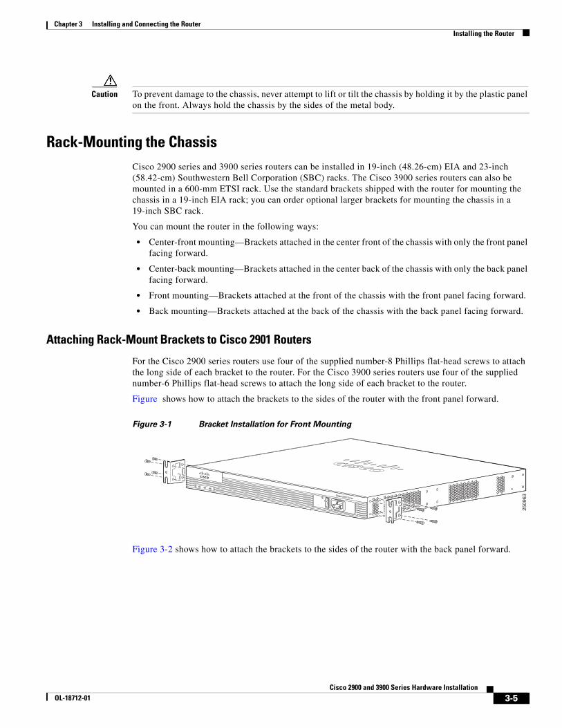
Attaching Rack-Mount Brackets to Cisco 2901 Routers
For the Cisco 2900 series routers use four of the supplied number-8 Phillips flat-head screws to attach the long side of each bracket to the router. For the Cisco 3900 series routers use four of the supplied number-6 Phillips flat-head screws to attach the long side of each bracket to the router.
Figure shows how to attach the brackets to the sides of the router with the front panel forward.
Figure 3-1 Bracket Installation for Front Mounting
Figure 3-2 shows how to attach the brackets to the sides of the router with the back panel forward.
2509
63
SYS ACT POE
Cisco 2900 Series
3-5Cisco 2900 and 3900 Series Hardware Installation
OL-18712-01

Chapter 3 Installing and Connecting the Router Installing the Router
Figure 3-2 Bracket Installation for Back Mounting
Figure 3-3 shows how to attach the brackets to the sides of the router with center mounting.
Figure 3-3 Bracket Installation for Center Mounting
Attaching Rack-Mount Brackets to Cisco 2911, Cisco 2921, and Cisco 2951 Routers
Attach the mounting brackets to the router chassis as shown in Figure 3-4 through Figure 3-7, using the screws provided.
Caution Do not over torque the screws. The recommended torque is 15 to 18 inch-lb (1.7 to 2.0 N-m).
Attach the second bracket to the opposite side of the chassis. Use a number-2 Phillips screwdriver to install the number-8 bracket screws.
Caution Your chassis installation must allow unrestricted airflow for chassis cooling.
DO NOT REMOVE DURINGNETWORK OPERATION
DO NOT REMOVE DURINGNETWORK OPERATION
2509
67
1
2509
64
SYS ACT POE
Cisco 2900 Series
3-6Cisco 2900 and 3900 Series Hardware Installation
OL-18712-01
Chapter 3 Installing and Connecting the Router Installing the Router
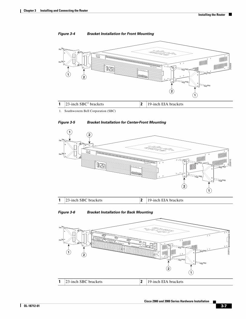
Figure 3-4 Bracket Installation for Front Mounting
Figure 3-5 Bracket Installation for Center-Front Mounting
Figure 3-6 Bracket Installation for Back Mounting
1 23-inch SBC1 brackets
1. Southwestern Bell Corporation (SBC)
2 19-inch EIA brackets
Cisco 2900 Series
2509
09
1 2
1 2
SYS ACT POE RPS PS
1 23-inch SBC brackets 2 19-inch EIA brackets
2509
10
1
1 2
2
Cisco 2900 Series
SYS ACT POE RPS PS
1 23-inch SBC brackets 2 19-inch EIA brackets
DO NOT REMOVE DURINGNETWORK OPERATION
DO NOT REMOVE DURINGNETWORK OPERATION
2509
12
1 2
1 2
3-7Cisco 2900 and 3900 Series Hardware Installation
OL-18712-01

Chapter 3 Installing and Connecting the Router Installing the Router
Figure 3-7 Bracket Installation for Center-Back Mounting
Attaching Rack-Mount Brackets to Cisco 3900 Series Routers
Attach the mounting brackets to the router chassis as shown in Figure 3-8 through Figure 3-11, using the screws provided.
Caution Do not over torque the screws. The recommended torque is 8 to 10 inch-lb (0.9 to 1.12 N-m).
Attach the second bracket to the opposite side of the chassis. Use a number-2 Phillips screwdriver to install the number-6 bracket screws.
Caution Your chassis installation must allow unrestricted airflow for chassis cooling.
Figure 3-8 Bracket Installation for Front Mounting
1 23-inch SBC brackets 2 19-inch EIA brackets
DO NOT REMOVE DURINGNETWORK OPERATION
DO NOT REMOVE DURINGNETWORK OPERATION
2509
13
1 2
1 2
1 23-inch EIA brackets 2 19-inch EIA brackets
2509
23
SYS ACT SYSPWR1
AUXPWR1
SYSPWR2
AUXPWR2
Cisco 3900 Series
12
12
3-8Cisco 2900 and 3900 Series Hardware Installation
OL-18712-01

Chapter 3 Installing and Connecting the Router Installing the Router
Figure 3-9 Bracket Installation for Center-Front Mounting
Figure 3-10 Bracket Installation for Rear Mounting
1 23-inch EIA brackets 2 19-inch EIA brackets
2509
24
SYS ACT SYSPWR1
AUXPWR1
SYSPWR2
AUXPWR2
Cisco 3900 Series
12
12
1 23-inch EIA brackets 2 19-inch EIA brackets
DO NOT REMOVE DURINGNETWORK OPERATION DO NOT REMOVE DURINGNETWORK OPERATION
2
2
3-9Cisco 2900 and 3900 Series Hardware Installation
OL-18712-01
Chapter 3 Installing and Connecting the Router Installing the Router
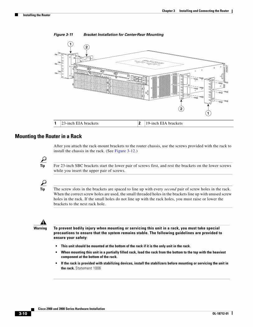
Figure 3-11 Bracket Installation for Center-Rear Mounting
Mounting the Router in a Rack
After you attach the rack-mount brackets to the router chassis, use the screws provided with the rack to install the chassis in the rack. (See Figure 3-12.)
Tip For 23-inch SBC brackets start the lower pair of screws first, and rest the brackets on the lower screws while you insert the upper pair of screws.
Tip The screw slots in the brackets are spaced to line up with every second pair of screw holes in the rack. When the correct screw holes are used, the small threaded holes in the brackets line up with unused screw holes in the rack. If the small holes do not line up with the rack holes, you must raise or lower the brackets to the next rack hole.
1 23-inch EIA brackets 2 19-inch EIA brackets
DO NOT REMOVE DURINGNETWORK OPERATION DO NOT REMOVE DURINGNETWORK OPERATION
2509
27
1 2
1 2
Warning To prevent bodily injury when mounting or servicing this unit in a rack, you must take special precautions to ensure that the system remains stable. The following guidelines are provided to ensure your safety:
• This unit should be mounted at the bottom of the rack if it is the only unit in the rack.
• When mounting this unit in a partially filled rack, load the rack from the bottom to the top with the heaviest component at the bottom of the rack.
• If the rack is provided with stabilizing devices, install the stabilizers before mounting or servicing the unit in the rack. Statement 1006
3-10Cisco 2900 and 3900 Series Hardware Installation
OL-18712-01
Chapter 3 Installing and Connecting the Router Installing the Router
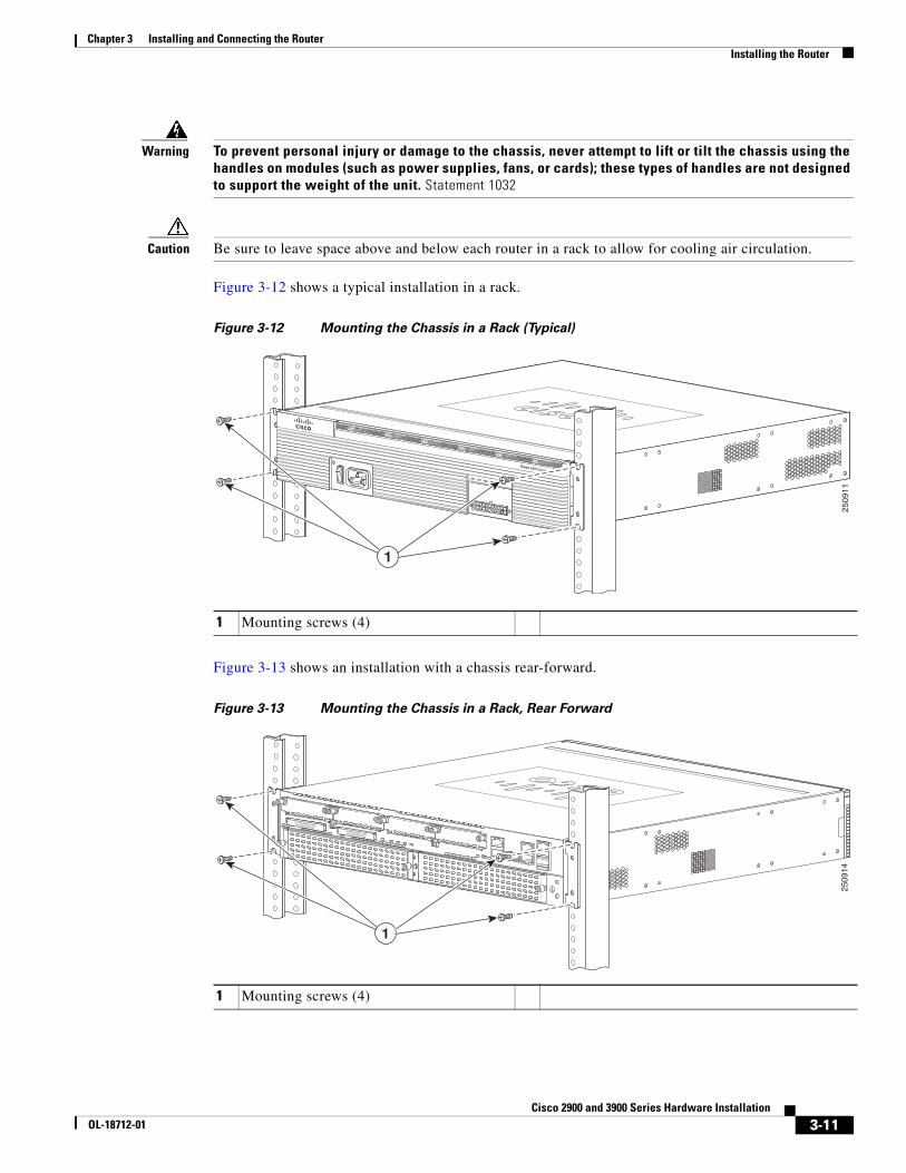
Warning To prevent personal injury or damage to the chassis, never attempt to lift or tilt the chassis using the handles on modules (such as power supplies, fans, or cards); these types of handles are not designed to support the weight of the unit. Statement 1032
Caution Be sure to leave space above and below each router in a rack to allow for cooling air circulation.
Figure 3-12 shows a typical installation in a rack.
Figure 3-12 Mounting the Chassis in a Rack (Typical)
Figure 3-13 shows an installation with a chassis rear-forward.
Figure 3-13 Mounting the Chassis in a Rack, Rear Forward
1 Mounting screws (4)
Cisco 2900 Series
SYS ACT POE RPS PS
2509
11
1
1 Mounting screws (4)
DO NOT REMOVE DURINGNETWORK OPERATION
DO NOT REMOVE DURINGNETWORK OPERATION
2509
14
1
3-11Cisco 2900 and 3900 Series Hardware Installation
OL-18712-01
Chapter 3 Installing and Connecting the Router Installing the Router
Grounding the Chassis
After the router is installed, you must connect the chassis to a reliable earth ground. For the chassis ground connection procedures, see the “Chassis Grounding” section on page 3-15.
Setting the Chassis on a DesktopYou can place Cisco 2901, Cisco 2911, and Cisco 3900 series routers on a desktop or shelf.
Note Models 2921 and above are not recommended for desktop mounting.
To install a Cisco 2901 or 2911 router on a desktop, first install the four rubber feet that are supplied in the accessory kit. They provide anti-skid protection and space for air circulation. Peel the rubber feet from the adhesive strip, and stick them onto the “+” marked on the bottom of the chassis.
Warning To prevent personal injury or damage to the chassis, never attempt to lift or tilt the chassis using the handles on modules (such as power supplies, fans, or cards); these types of handles are not designed to support the weight of the unit. Statement 1032
Caution Do not place anything on top of the router that weighs more than 10 pounds (4.5 kg), and do not stack routers on a desktop. Excessive distributed weight of more than 10 pounds, or pound point load of 10 pounds on top could damage the chassis.
Caution Your chassis installation must allow unrestricted airflow for chassis cooling. For placing the router on a desktop, keep at least 1 inch (2.54 cm) of clear space beside the cooling inlet and exhaust vents.
After the router is installed, you must connect the chassis to a reliable earth ground. For the chassis ground connection procedures, see the “Chassis Grounding” section on page 3-15.
3-12Cisco 2900 and 3900 Series Hardware Installation
OL-18712-01

Chapter 3 Installing and Connecting the Router Installing the Router
Mounting a Cisco 2901 or 2911 Router on a WallThis section explains how to mount Cisco 2901 and Cisco 2911 routers on a wall or other vertical surface. We do not recommend mounting a Cisco 2921, 2951, or Cisco 3900 series router on a wall.
The following warning applies to Cisco 2901 and 2911 routers:
Warning This unit is intended to be mounted on a wall. Please read the wall mounting instructions carefully before beginning installation. Failure to use the correct hardware or to follow the correct procedures could result in a hazardous situation to people and damage to the system. Statement 248
Tip When choosing a wall-mounting location, consider cable limitations and wall structure.
Note The Cisco 2901 and Cisco 2911 routers use brackets designed for the 19-inch EIA rack-mounting, the part number 700-16559-01 is stamped on the bracket (shown in Figure 3-15).
Attaching Brackets to the Router for Wall Mounting
Attach the standard brackets to the chassis using the four screws provided for each bracket.
Attaching the Router to a Wall
Attach the router to the wall using the brackets previously attached. Use attachment hardware that you provide as follows:
• For attaching to a wall stud, each bracket requires two number-10 wood screws (round- or pan-head) with number-10 washers, or two number-10 washer-head screws. The screws must be long enough to penetrate at least 1.5 inches (38.1 mm) into the supporting wood or metal wall stud.
• For hollow-wall mounting, each bracket requires two wall anchors with washers. Wall anchors and washers must be size number 10.
• Route the cables so that they do not put a strain on the connectors or mounting hardware.
• The NEBS air baffle (Cisco 2911) should not be used when wall-mounting the router.
Caution This unit is intended to be mounted on a wall. Please read the wall mounting instructions carefully before beginning installation. Failure to use the correct hardware or to follow the correct procedures could result in a hazardous situation to people and damage to the system.
Caution The router must be mounted with the power connections oriented downward. Failure to do so could present a fire hazard.
3-13Cisco 2900 and 3900 Series Hardware Installation
OL-18712-01

Chapter 3 Installing and Connecting the Router Installing the Router
Figure 3-14 and Figure 3-15 show typical wall-mounted installations.
Figure 3-14 Mounting the 2901 Chassis on the Wall
Figure 3-15 Mounting the 2911 Chassis on the Wall
2509
68
2527
30
3-14Cisco 2900 and 3900 Series Hardware Installation
OL-18712-01

Chapter 3 Installing and Connecting the Router Chassis Grounding
After the router is installed, you must connect the chassis to a reliable earth ground. For the chassis ground connection procedures, see the “Chassis Grounding” section on page 3-15.
Chassis Grounding
Warning This equipment must be grounded. Never defeat the ground conductor or operate the equipment in the absence of a suitably installed ground conductor. Contact the appropriate electrical inspection authority or an electrician if you are uncertain that suitable grounding is available. Statement 1024
Warning During this procedure, wear grounding wrist straps to avoid ESD damage to the card. Do not directly touch the backplane with your hand or any metal tool, you could shock yourself. Statement 94
You must connect the chassis to a reliable earth ground; the ground wire must be installed in accordance with local electrical safety standards.
• For NEBS-compliant grounding, use size 6 AWG (13 mm2) copper wire and the ground lug provided in the accessory kit.
Note NEBS-compliant grounding is not supported on the Cisco 2901 router.
Note This equipment is suitable for installation in Network Telecommunications Facilities and locations where the NEC applies. The equipment is suitable for installation as part of the Common Bonding Network (CBN).
• For NEC-compliant grounding, use size 14 AWG (2 mm2) or larger copper wire and an appropriate user-supplied ring terminal with an inner diameter of 1/4 in. (5–7 mm).
• For EN/IEC 60950-compliant grounding, use size 18 AWG (1 mm2) or larger copper wire and an appropriate user-supplied ring terminal.
To install the ground connection for a Cisco 2900 or Cisco 3900 series router, perform the following steps:
Step 1 Strip one end of the ground wire to the length required for the ground lug or terminal.
• For the NEBS ground lug—approximately 0.75 inch (20 mm)
• For user-provided ring terminal—as required
Step 2 Crimp the ground wire to the ground lug or ring terminal, using a crimp tool of the appropriate size.
Step 3 Attach the ground lug or ring terminal to the chassis as shown in Figure 3-16, Figure 3-17, Figure 3-18, Figure 3-18, or Figure 3-19. For a ground lug, use the two screws with captive locking washers provided. For a ring terminal, use one of the screws provided. Tighten the screws to a torque of 8 to 10 in-lb (0.9 to 1.1 N-m).
3-15Cisco 2900 and 3900 Series Hardware Installation
OL-18712-01

Chapter 3 Installing and Connecting the Router Chassis Grounding
Figure 3-16 Chassis Ground Connection Using Ring Terminal on Cisco 2901 Chassis
Figure 3-17 NEBS-Compliant Chassis Ground Connection on Cisco 2911 Chassis
2509
84
2509
83
3-16Cisco 2900 and 3900 Series Hardware Installation
OL-18712-01
Chapter 3 Installing and Connecting the Router Chassis Grounding
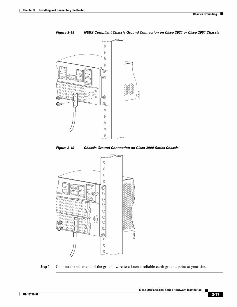
Figure 3-18 NEBS-Compliant Chassis Ground Connection on Cisco 2921 or Cisco 2951 Chassis
Figure 3-19 Chassis Ground Connection on Cisco 3900 Series Chassis
Step 4 Connect the other end of the ground wire to a known reliable earth ground point at your site.
2509
15
L
2509
29
3-17Cisco 2900 and 3900 Series Hardware Installation
OL-18712-01
Chapter 3 Installing and Connecting the Router Connecting Power
Connecting PowerThis section explains how to connect AC or DC power to Cisco 2900 series routers. It covers the following topics:
• Connecting to AC Power, page 3-18
• Connecting to DC Power, page 3-19
• Connecting to Backup Power, page 3-30
Warning Read the installation instructions before connecting the system to the power source. Statement 1004
Warning This unit might have more than one power supply connection. All connections must be removed to de-energize the unit. Statement 1028
Warning Only trained and qualified personnel should be allowed to install, replace, or service this equipment. Statement 1030
Note The installation must comply with all required electrical codes applicable at the installation site.
Connecting to AC PowerIf your router uses AC power, connect it to a 15 A, 120 VAC (10 A, 240 VAC) circuit with overcurrent protection. If backup power is required, see the “Connecting to Backup Power” section on page 3-30.
Note The input voltage tolerance limits for AC power are 90 and 264 VAC.
Note This product requires surge protection to be provided as part of the building installation. To comply with the Telcordia GR-1089 NEBS standard for electromagnetic compatibility and safety, an external surge protective device (SPD) is required at the AC power service equipment.
Warning AC connected units must have a permanent ground connection in addition to the power cable ground wire. NEBS-compliant grounding satisfies this requirement. Statement 284
Warning This product requires short-circuit (overcurrent) protection, to be provided as part of the building installation. Install only in accordance with national and local wiring regulations. Statement 1045
3-18Cisco 2900 and 3900 Series Hardware Installation
OL-18712-01
Chapter 3 Installing and Connecting the Router Connecting Power
Warning This product relies on the building’s installation for short-circuit (overcurrent) protection. Ensure that the protective device is rated not greater than:15A, 120VAC (16A, 240VAC). Statement 1005
Connecting to DC PowerIf your router has a DC-input power supply, follow the directions in this section for proper wiring. A router with a DC-input power supply has a terminal block for the DC power connections. If backup power is required, see the “Connecting to Backup Power” section.
• DC Wiring Requirements for Cisco 2911, 2921, and 2951 Routers, page 3-19
• Wiring Procedure for DC Input on Cisco 2911, 2921, and 2951 Routers, page 3-20
• Approved Scenarios and Scenarios Not Approved for Dual DC Power Supply Configuration on Cisco 2911, 2921, and 2951 Routers, page 3-23
• DC Wiring Requirements for Cisco 3900 Series Routers, page 3-24
Caution DC return is isolated from the frame. (NEBS DC-I)
Warning This product requires short-circuit (overcurrent) protection, to be provided as part of the building installation. Install only in accordance with national and local wiring regulations. Statement 1045
Warning This product relies on the building's installation for short-circuit (overcurrent) protection. Ensure that the protective device is rated not greater than: 60 VDC, 20 A. Statement 1005
Warning Only trained and qualified personnel should be allowed to install, replace, or service this equipment. Statement 1030
Warning Use copper conductors only. Statement 1025
DC Wiring Requirements for Cisco 2911, 2921, and 2951 Routers
A Cisco 2911, Cisco 2921, or Cisco 2951 router with a DC-input power supply requires copper wire and crimp-type terminals for the power connections. Table 3-1 and Table 3-2 summarize the wiring requirements.
You can connect a single DC power source to either the A input or the B input. If there are dual power sources, connect one source to the A input and one source to the B input; both sources must be the same polarity and voltage.
3-19Cisco 2900 and 3900 Series Hardware Installation
OL-18712-01

Chapter 3 Installing and Connecting the Router Connecting Power
Wiring Procedure for DC Input on Cisco 2911, 2921, and 2951 Routers
To connect a router to a DC power source, perform the following steps:
Step 1 Remove power from the DC circuit. To ensure that power is removed from the DC circuit, locate the circuit breaker for the DC circuit, switch the circuit breaker to the OFF position.
Warning Follow proper Lockout /Tagout Procedures as defined by your company in accordance with local and national laws (e.g. Title 29 CFR Part 1910.147).
Warning Before performing any of the following procedures, ensure that power is removed from the DC circuit. Statement 1003
Warning Use copper conductors only. Statement 1025
Warning Only trained and qualified personnel should be allowed to install, replace, or service this equipment. Statement 1030
Table 3-1 DC Wiring Requirements for Cisco 2911 Routers
DC Power Input DC Input Wire Size
Safety Ground Wire Size
Wire Terminal (Lug)
Overcurrent Protection
24-36 VDC, 11 A, positive or negative, single source or dual sources
AWG 14 (2.0 mm2)
AWG 14 (2.0 mm2), minimum
Amp/Tyco No. 32957
20 A maximum
36-60 VDC, 4 A, positive or negative, single source or dual sources
Table 3-2 DC Wiring Requirements for Cisco 2921 and 2951 Routers
DC Power Input DC Input Wire Size
Safety Ground Wire Size
Wire Terminal (Lug)
Overcurrent Protection
24-36 VDC, 17 A, positive or negative, single source or dual sources
AWG 14 (2.0 mm2)
AWG 14 (2.0 mm2), minimum
Amp/Tyco No. 32957
20 A maximum
36-60 VDC, 7 A, positive or negative, single source or dual sources
3-20Cisco 2900 and 3900 Series Hardware Installation
OL-18712-01
Chapter 3 Installing and Connecting the Router Connecting Power
Tip Tip Secure all power cabling when installing this unit to avoid disturbing field-wiring connections.
Warning When stranded wiring is required, use approved wiring terminations, such as closed-loop or spade-type with upturned lugs. These terminations should be the appropriate size for the wires and should clamp both the insulation and conductor. Statement 1002
Step 2 Strip the wires to the appropriate length for the terminals. The strip length is 5/64 to 1/8 inch (2 to 4 mm) for Amp/Tyco No. 32957 terminals.
Step 3 Crimp the terminals to the power input and safety ground wires.
Step 4 Remove the plastic covers from the terminal block. Save the covers for reinstallation after you finish wiring.
Step 5 Connect the wires to the terminal block, starting with the safety ground wire. Connect each wire to the appropriate terminal as shown in Figure 1. Tighten the terminal screws to 8.0 ± 0.5 in-lb (0.9 ± 0.05 N-m).
Warning This unit might have more than one power supply connection. All connections must be removed to de-energize the unit. Statement 1028
Warning The illustration shows the DC power supply terminal block. Wire the DC power supply as illustrated. The proper wiring sequence is ground to ground, positive to positive, and negative to negative. The ground wire should always be connected first and disconnected last. Statement 239
Warning An exposed wire lead from a DC-input power source can conduct harmful levels of electricity. Be sure that no exposed portion of the DC-input power source wire extends from the terminal block plug. Statement 122
Caution Dual sources with opposite-polarity grounding damage equipment.
Caution Caution Do not overtorque the terminal block contact screws. Recommended torque is 5.0 ± 0.5 in-lb (0.56 ± 0.06 N-m) for 2911 series routers, and 9 ± 1.0 in-lb (1.02 ± 0.11 N-m)
3-21Cisco 2900 and 3900 Series Hardware Installation
OL-18712-01
Chapter 3 Installing and Connecting the Router Connecting Power
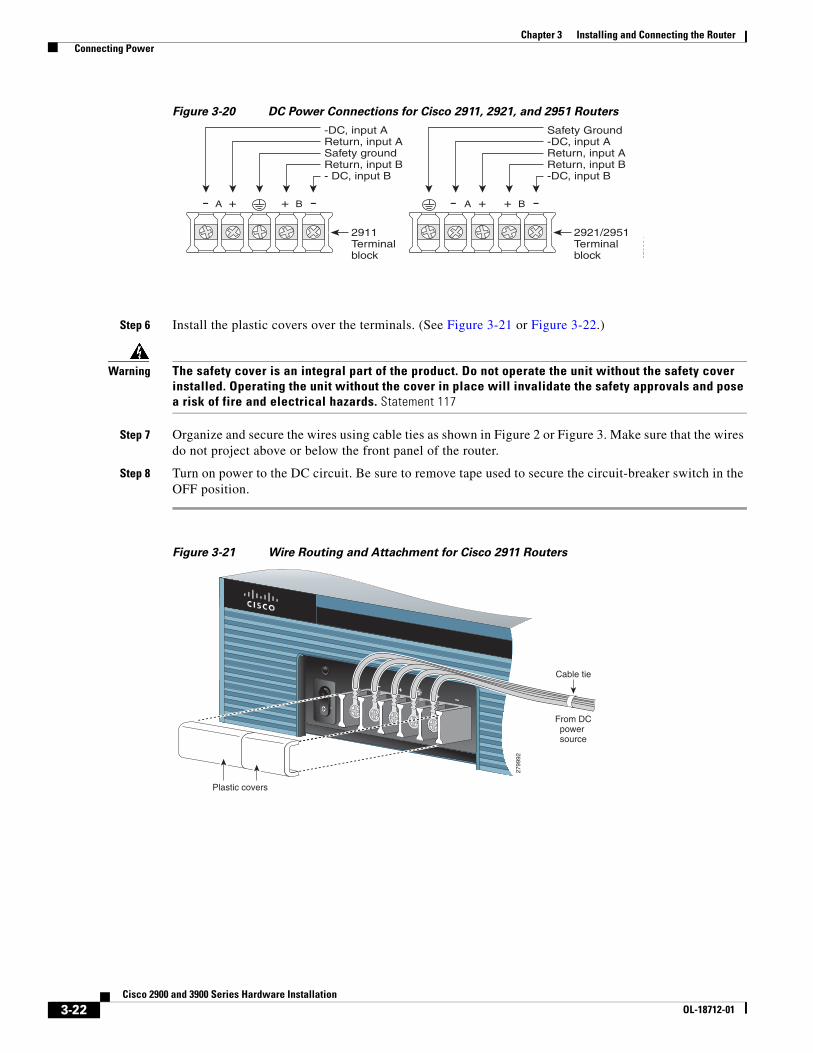
Figure 3-20 DC Power Connections for Cisco 2911, 2921, and 2951 Routers
Step 6 Install the plastic covers over the terminals. (See Figure 3-21 or Figure 3-22.)
Warning The safety cover is an integral part of the product. Do not operate the unit without the safety cover installed. Operating the unit without the cover in place will invalidate the safety approvals and pose a risk of fire and electrical hazards. Statement 117
Step 7 Organize and secure the wires using cable ties as shown in Figure 2 or Figure 3. Make sure that the wires do not project above or below the front panel of the router.
Step 8 Turn on power to the DC circuit. Be sure to remove tape used to secure the circuit-breaker switch in the OFF position.
Figure 3-21 Wire Routing and Attachment for Cisco 2911 Routers
A + + B
2921/2951Terminalblock
A + + B
2911Terminalblock 27
9991
-DC, input AReturn, input ASafety groundReturn, input B- DC, input B
Safety Ground-DC, input AReturn, input AReturn, input B-DC, input B
2799
92
- + + -
From DCpower source
Cable tie
Plastic covers
3-22Cisco 2900 and 3900 Series Hardware Installation
OL-18712-01

Chapter 3 Installing and Connecting the Router Connecting Power
Figure 3-22 Wire Routing and Attachment for Cisco 2921 and Cisco 2951 Routers
Approved Scenarios and Scenarios Not Approved for Dual DC Power Supply Configuration on Cisco 2911, 2921, and 2951 Routers
You can connect a single DC power source to either the A input or the B input. If there are dual power sources, connect one source to the A input and one source to the B input. Both sources must be the same polarity (with respect to ground) and voltage (within 0.25 volts). Do not connect –DC grounded and +DC grounded dual sources to Cisco 2911, Cisco 2921, and Cisco 2951 routers.
Caution Dual sources with opposite-polarity grounding damage equipment.
In Figure 3-23, either the positive source terminal or the negative source terminal is tied to ground.
Figure 3-23 Connecting to One Source Only—Source A or Source B
2799
93
- GND
+ + -From DCpower source
Cable tie
Plastic covers
A-
3614
70A+
B+
B-
+
A-
A+
B+
B-
+
BatterySource
BatterySource
3-23Cisco 2900 and 3900 Series Hardware Installation
OL-18712-01
Chapter 3 Installing and Connecting the Router Connecting Power
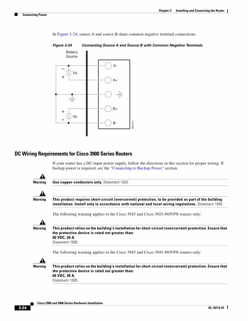
In Figure 3-24, source A and source B share common negative terminal connections.
Figure 3-24 Connecting Source A and Source B with Common Negative Terminals
DC Wiring Requirements for Cisco 3900 Series Routers
If your router has a DC-input power supply, follow the directions in this section for proper wiring. If backup power is required, see the “Connecting to Backup Power” section.
Warning Use copper conductors only. Statement 1025
Warning This product requires short-circuit (overcurrent) protection, to be provided as part of the building installation. Install only in accordance with national and local wiring regulations. Statement 1045
The following warning applies to the Cisco 3925 and Cisco 3925-NOVPN routers only:
Warning This product relies on the building's installation for short-circuit (overcurrent) protection. Ensure that the protective device is rated not greater than: 60 VDC, 20 A. Statement 1005
The following warning applies to the Cisco 3945 and Cisco 3945-NOVPN routers only:
Warning This product relies on the building's installation for short-circuit (overcurrent) protection. Ensure that the protective device is rated not greater than: 60 VDC, 30 A. Statement 1005
A-
3614
71
A+
B+
B-
Va
Vb
+
+
BatterySource
3-24Cisco 2900 and 3900 Series Hardware Installation
OL-18712-01
Chapter 3 Installing and Connecting the Router Connecting Power
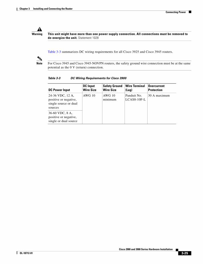
Warning This unit might have more than one power supply connection. All connections must be removed to de-energize the unit. Statement 1028
Table 3-3 summarizes DC wiring requirements for all Cisco 3925 and Cisco 3945 routers.
Note For Cisco 3945 and Cisco 3945-NOVPN routers, the safety ground wire connection must be at the same potential as the 0 V (return) connection.
Table 3-3 DC Wiring Requirements for Cisco 3900
DC Power Input DC Input Wire Size
Safety Ground Wire Size
Wire Terminal (Lug)
Overcurrent Protection
24-36 VDC, 12 A, positive or negative, single source or dual sources
AWG 10 AWG 10 minimum
Panduit No. LCAS8-10F-L
30 A maximum
36-60 VDC, 8 A, positive or negative, single or dual source
3-25Cisco 2900 and 3900 Series Hardware Installation
OL-18712-01

Chapter 3 Installing and Connecting the Router Connecting Power
Cisco 3900 Series Router Wiring Procedure for DC Input
To connect the router to a DC power source, follow these steps:
Step 1 Remove power from the DC circuit. To ensure that power is removed from the DC circuit, locate the circuit breaker for the DC circuit, switch the circuit breaker to the OFF position.
Warning Follow proper Lockout /Tagout Procedures as defined by your company in accordance with local and national laws (e.g. Title 29 CFR Part 1910.147).
Warning Before performing any of the following procedures, ensure that power is removed from the DC circuit. Statement 1003
Tip Secure all power cabling when installing this unit to avoid disturbing field-wiring connections.
Warning When stranded wiring is required, use approved wiring terminations, such as closed-loop or spade-type with upturned lugs. These terminations should be the appropriate size for the wires and should clamp both the insulation and conductor. Statement 1002
Step 2 Strip the wires to the appropriate length for the terminals. The length is 3/16 to 1/4 inch (5 to 6 mm) for Panduit No. LCAS8-10F-L terminals.
Step 3 Crimp the terminals onto the DC power input and safety ground wires.
Step 4 Remove the plastic covers from the terminal block. Save the covers for reinstallation after you finish wiring.
Step 5 Connect the wires to the terminal block, starting with the safety ground wire. Connect each wire to the appropriate terminal as shown in Figure 3-25.
Warning The illustration shows the DC power supply terminal block. Wire the DC power supply as illustrated. The proper wiring sequence is ground to ground, positive to positive, and negative to negative. The ground wire should always be connected first and disconnected last. Statement 239
Warning An exposed wire lead from a DC-input power source can conduct harmful levels of electricity. Be sure that no exposed portion of the DC-input power source wire extends from the terminal block plug. Statement 122
Caution Do not overtorque the terminal block screws. The recommended torque is 18.0 – 20.0 in-lb (2.03 – 2.26 N-m).
3-26Cisco 2900 and 3900 Series Hardware Installation
OL-18712-01
Chapter 3 Installing and Connecting the Router Connecting Power
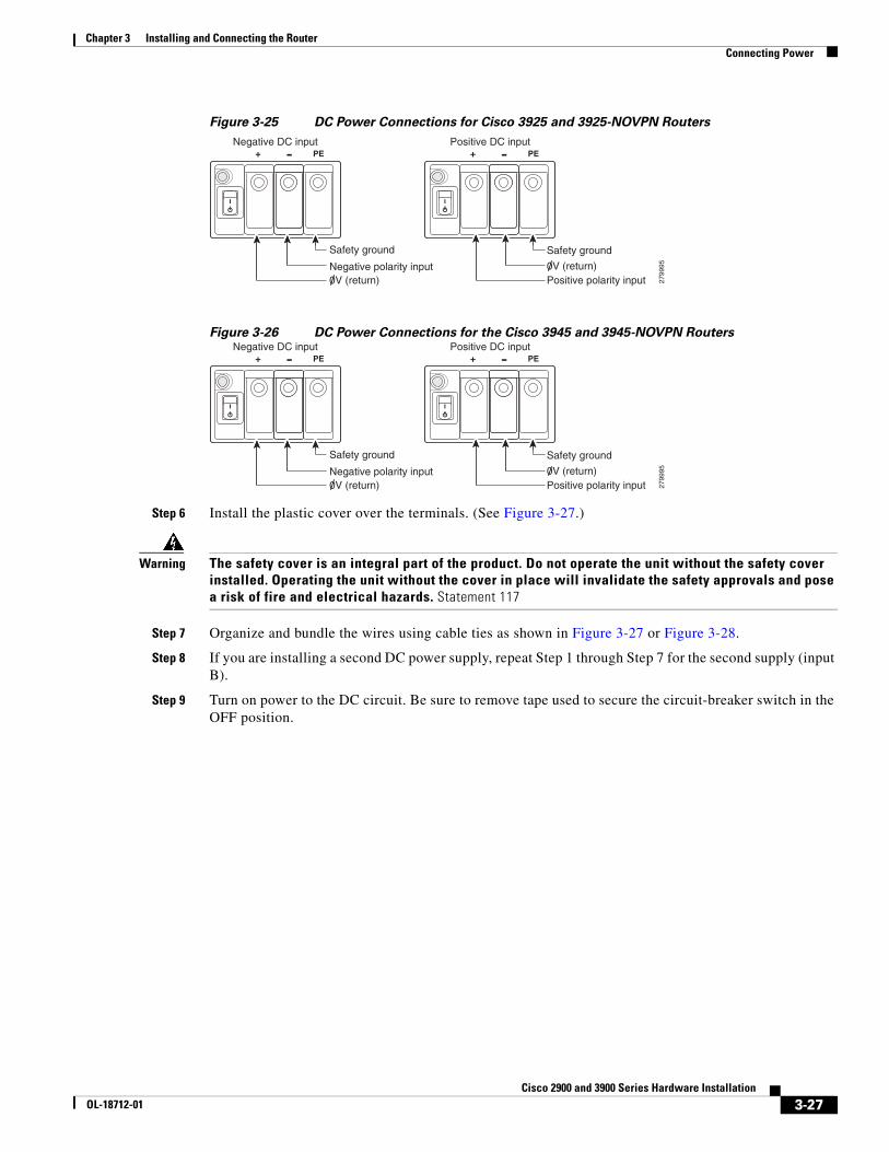
Figure 3-25 DC Power Connections for Cisco 3925 and 3925-NOVPN Routers
Figure 3-26 DC Power Connections for the Cisco 3945 and 3945-NOVPN Routers
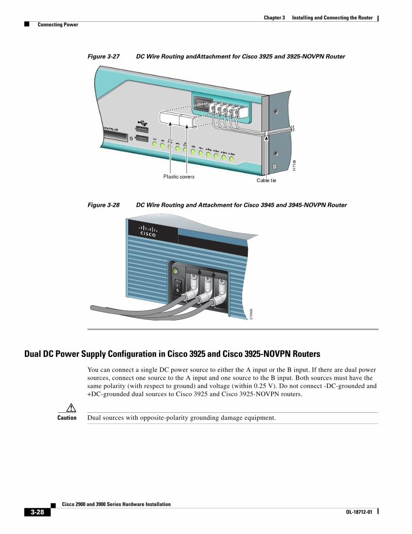
Step 6 Install the plastic cover over the terminals. (See Figure 3-27.)
Warning The safety cover is an integral part of the product. Do not operate the unit without the safety cover installed. Operating the unit without the cover in place will invalidate the safety approvals and pose a risk of fire and electrical hazards. Statement 117
Step 7 Organize and bundle the wires using cable ties as shown in Figure 3-27 or Figure 3-28.
Step 8 If you are installing a second DC power supply, repeat Step 1 through Step 7 for the second supply (input B).
Step 9 Turn on power to the DC circuit. Be sure to remove tape used to secure the circuit-breaker switch in the OFF position.
2799
95
PE+Negative DC input
PE+Positive DC input
0V (return)Negative polarity input
Safety ground
Positive polarity input0V (return)
Safety ground
2799
95
PE+Negative DC input
PE+Positive DC input
0V (return)Negative polarity input
Safety ground
Positive polarity input0V (return)
Safety ground
3-27Cisco 2900 and 3900 Series Hardware Installation
OL-18712-01
Chapter 3 Installing and Connecting the Router Connecting Power
Figure 3-27 DC Wire Routing andAttachment for Cisco 3925 and 3925-NOVPN Router
Figure 3-28 DC Wire Routing and Attachment for Cisco 3945 and 3945-NOVPN Router
Dual DC Power Supply Configuration in Cisco 3925 and Cisco 3925-NOVPN Routers
You can connect a single DC power source to either the A input or the B input. If there are dual power sources, connect one source to the A input and one source to the B input. Both sources must have the same polarity (with respect to ground) and voltage (within 0.25 V). Do not connect -DC-grounded and +DC-grounded dual sources to Cisco 3925 and Cisco 3925-NOVPN routers.
Caution Dual sources with opposite-polarity grounding damage equipment.
2799
96
3-28Cisco 2900 and 3900 Series Hardware Installation
OL-18712-01

Chapter 3 Installing and Connecting the Router Connecting Power
In Figure 3-29, either the positive source terminal or the negative source terminal is tied to ground.
Figure 3-29 Connecting to One Source Only—Source A or Source B
In Figure 3-30, source A and source B share common negative terminal connections.
Figure 3-30 Connecting Source A and Source B with Common Negative Terminals
A-
3614
70
A+
B+
B-
+
A-
A+
B+
B-
+
BatterySource
BatterySource
A-
3614
71
A+
B+
B-
Va
Vb
+
+
BatterySource
3-29Cisco 2900 and 3900 Series Hardware Installation
OL-18712-01

Chapter 3 Installing and Connecting the Router Connecting to a Console Terminal or Modem
Connecting to Backup PowerThe redundant power supply (RPS) for the Cisco 2911, Cisco 2921, and Cisco 2951 router is an external Cisco RPS 2300. To connect the RPS, the router must be fitted with an RPS adapter. See the “Installing and Removing a Redundant Power Supply Adapter” section on page 5-42 before connecting to a backup power source.
If your router uses the Cisco Redundant Power System (RPS), see the Cisco Redundant Power System 2300 Hardware Installation Guide for instructions about the power connections. You can access this document at:
http://www.cisco.com/en/US/docs/switches/power_supplies/rps2300/hardware/installation/guide/2300hig.html
Caution Before connecting the RPS to the router, make sure that either the RPS is in standby mode or the RPS AC power is disconnected. Connecting the RPS to AC power automatically places the RPS in active mode.
Note The Cisco 2901 router does not support an RPS.
Connecting to a Console Terminal or ModemThe router has asynchronous serial ports and auxiliary ports. These ports provide administrative access to the router either locally (with a console terminal or a PC) or remotely (with a modem).To configure the router through the Cisco IOS CLI, you must establish a connection between the router console port and either a terminal or a PC.
Use the following cables and adapters to establish a local or remote connection.
Connecting to the Serial Port with Microsoft Windows
Note Install the USB device driver before establishing a physical connection between the router and the PC using the USB Console cable plugged into the USB serial port, otherwise the connection will fail. See the “Installing the Cisco Microsoft Windows USB Device Driver” section on page 3-35.
Table 3-4 Local and Remote Connections
Port Type Cable Section
Serial (RJ-45) EIA RJ-45 Connecting to the Serial Port with Microsoft WindowsSerial (USB) USB 5-pin mini USB Type-B-to-USB
Type-A
Auxiliary (Modem) DB-9-to-DB-25 Connecting to the Auxiliary Port
3-30Cisco 2900 and 3900 Series Hardware Installation
OL-18712-01

Chapter 3 Installing and Connecting the Router Connecting to a Console Terminal or Modem
Step 1 Connect the end of the console cable with the RJ-45 connector to the light blue console port on the router.
or
Connect a USB 5-pin mini USB Type-B to the USB console port as shown in Figure 3-31, Figure 3-32 or Figure 3-33. If you are using the USB serial port for the first time on a Windows-based PC, install the USB driver now according to the instructions in the following sections.
• “Installing the Cisco Microsoft Windows XP USB Driver” section on page 3-35
• “Installing the Cisco Microsoft Windows 2000 USB Driver” section on page 3-36
• “Installing the Cisco Microsoft Windows Vista USB Driver” section on page 3-36
Note You cannot use the USB port and the EIA port concurrently. See “Connecting to the Auxiliary Port” section on page 3-38. When the USB port is used it takes priority over the RJ-45 EIA port.
Step 2 Connect the end of the cable with the DB-9 connector (or USB Type-A) to the terminal or PC. If your terminal or PC has a console port that does not accommodate a DB-9 connector, you must provide an appropriate adapter for that port.
Step 3 To communicate with the router, start a terminal emulator application, such as Microsoft Windows HyperTerminal. This software should be configured with the following parameters:
• 9600 baud
• 8 data bits
• no parity
• 1 stop bit
• no flow control
3-31Cisco 2900 and 3900 Series Hardware Installation
OL-18712-01

Chapter 3 Installing and Connecting the Router Connecting to a Console Terminal or Modem
Figure 3-31 Connecting the USB Console Cable to the Cisco 2901 Router
1 USB 5-pin mini USB Type-B console port 2 USB 5-pin mini USB Type-B to USB Type-A console cable
3 USB Type-A
DO NOT REMOVE DURINGNETWORK OPERATION
DO NOT REMOVE DURINGNETWORK OPERATION
3
2
2516
03
2
CONSOLE
AUX
1
EN
1
3-32Cisco 2900 and 3900 Series Hardware Installation
OL-18712-01
Chapter 3 Installing and Connecting the Router Connecting to a Console Terminal or Modem
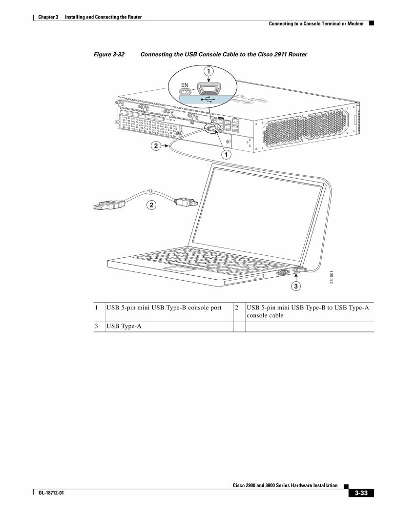
Figure 3-32 Connecting the USB Console Cable to the Cisco 2911 Router
1 USB 5-pin mini USB Type-B console port 2 USB 5-pin mini USB Type-B to USB Type-A console cable
3 USB Type-A
DO NOT REMOVE DURINGNETWORK OPERATION
DO NOT REMOVE DURINGNETWORK OPERATION
CONSOLE
AUX
2516
01
3
2
2
1
EN
1
3-33Cisco 2900 and 3900 Series Hardware Installation
OL-18712-01

Chapter 3 Installing and Connecting the Router Connecting to a Console Terminal or Modem
Figure 3-33 Connecting the USB Console Cable to the Cisco 2921, 2951, 3925 and 3945 Routers
Connecting to the Console Port with Mac OS XThis procedure describes how to connect a Mac OS X system USB port to the console using the built in OS X Terminal utility.
Step 1 Use the Finder to go to Applications > Utilities > Terminal.
Step 2 Connect the OS X USB port to the router.
Step 3 Enter the following commands to find the OS X USB port number
macbook:user$ cd /devmacbook:user$ ls -ltr /dev/*usb*crw-rw-rw- 1 root wheel 9, 66 Apr 1 16:46 tty.usbmodem1a21DT-macbook:dev user$
Step 4 Connect to the USB port with the following command followed by the router USB port speed
1 USB 5-pin mini USB Type-B console port 2 USB 5-pin mini USB Type-B to USB Type-A console cable
3 USB Type-A
DO NOT REMOVE DURINGNETWORK OPERATION DO NOT REMOVE DURINGNETWORK OPERATION
CONSOLE
AUX
2516
05
3
2
2
1
EN
1
3-34Cisco 2900 and 3900 Series Hardware Installation
OL-18712-01

Chapter 3 Installing and Connecting the Router Installing the Cisco Microsoft Windows USB Device Driver
macbook:user$ screen /dev/tty.usbmodem1a21 9600
To disconnect the OS X USB console from the Terminal window
Enter Ctrl-a followed by Ctrl-\
Connecting to the Console Port with LinuxThis procedure shows how to connect a Linux system USB port to the console using the built in Linux Terminal utility.
Step 1 Open the Linux Terminal window.
Step 2 Connect the Linux USB port to the router.
Step 3 Enter the following commands to find the Linux USB port number
root@usb-suse# cd /devroot@usb-suse /dev# ls -ltr *ACM*crw-r--r-- 1 root root 188, 0 Jan 14 18:02 ttyACM0root@usb-suse /dev#
Step 4 Connect to the USB port with the following command followed by the router USB port speed
root@usb-suse /dev# screen /dev/ttyACM0 9600
To disconnect the Linux USB console from the Terminal window
Enter Ctrl-a followed by : then quit
Installing the Cisco Microsoft Windows USB Device DriverA USB device driver must be installed the first time a Microsoft Windows-based PC is connected to the USB serial port on the router.
This section contains the following topics:
• “Installing the Cisco Microsoft Windows XP USB Driver”
• “Installing the Cisco Microsoft Windows 2000 USB Driver”
• “Installing the Cisco Microsoft Windows Vista USB Driver”
Installing the Cisco Microsoft Windows XP USB DriverThis procedure shows how to install the Microsoft Windows XP USB driver. Download the driver for your router model from the Tools and Resources Download Software site, USB Console Software category:
www.cisco.com/cisco/pub/software/portal/select.html?mdfid=268437899&?i=rp
Step 1 Unzip the file Cisco_usbconsole_driver_X_X.zip (where X is a revision number).
3-35Cisco 2900 and 3900 Series Hardware Installation
OL-18712-01

Chapter 3 Installing and Connecting the Router Installing the Cisco Microsoft Windows USB Device Driver
Step 2 If using 32-bit Windows XP double-click the file setup.exe from the Windows_32 folder, or if using 64-bit Windows XP double-click the file setup(x64).exe from the Windows_64 folder.
Step 3 The Cisco Virtual Com InstallShield Wizard begins. Click Next.
Step 4 The Ready to Install the Program window appears, Click Install.
Step 5 The InstallShield Wizard Completed window appears. Click Finish.
Step 6 Connect the USB cable to the PC and router USB console ports. See Table 3-1. The EN LED for the USB console port turns green, and within a few moments the Found New Hardware Wizard appears. Following the instructions to complete the installation of the driver.
Step 7 The USB console is ready for use.
Installing the Cisco Microsoft Windows 2000 USB DriverThis procedure shows how to install the Microsoft Windows 2000 USB driver.
Step 1 Obtain the file Cisco_usbconsole_driver.zip from the Cisco.com web site and unzip it.
Step 2 Double-click the file setup.exe.
Step 3 The Cisco Virtual Com InstallShield Wizard begins. Click Next.
Step 4 The Ready to Install the Program window appears, Click Install.
Step 5 The InstallShield Wizard Completed window appears. Click Finish.
Step 6 Connect the USB cable to the PC and router USB console ports. See Table 3-1. The EN LED for the USB console port turns green, and within a few moments a series of Found New Hardware Wizard windows appear. Following the instructions to complete the installation of the driver.
Step 7 The USB console is ready for use.
Installing the Cisco Microsoft Windows Vista USB DriverThis procedure shows how to install the Microsoft Windows Vista USB driver.
Step 1 Obtain the file Cisco_usbconsole_driver.zip from the Cisco.com web site and unzip it.
Step 2 If using 32-bit Windows Vista double-click the file setup.exe from the Windows_32 folder, or if using 64-bit Windows Vista double-click the file setup(x64).exe from the Windows_64 folder.
Step 3 The Cisco Virtual Com InstallShield Wizard begins. Click Next.
Step 4 The Ready to Install the Program window appears, Click Install.
Note If a User Account Control warning appears, click “Allow - I trust this program...” to proceed.
Step 5 The InstallShield Wizard Completed window appears. Click Finish.
3-36Cisco 2900 and 3900 Series Hardware Installation
OL-18712-01
Chapter 3 Installing and Connecting the Router Uninstalling the Cisco Microsoft Windows USB Driver
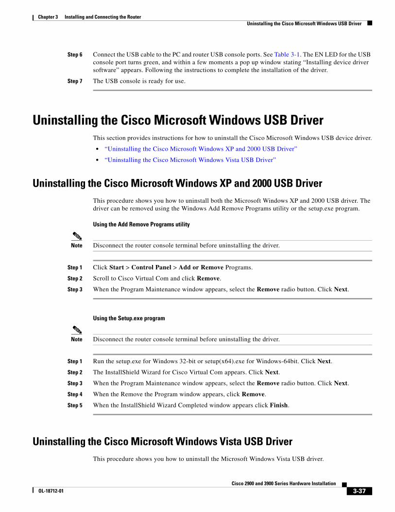
Step 6 Connect the USB cable to the PC and router USB console ports. See Table 3-1. The EN LED for the USB console port turns green, and within a few moments a pop up window stating “Installing device driver software” appears. Following the instructions to complete the installation of the driver.
Step 7 The USB console is ready for use.
Uninstalling the Cisco Microsoft Windows USB DriverThis section provides instructions for how to uninstall the Cisco Microsoft Windows USB device driver.
• “Uninstalling the Cisco Microsoft Windows XP and 2000 USB Driver”
• “Uninstalling the Cisco Microsoft Windows Vista USB Driver”
Uninstalling the Cisco Microsoft Windows XP and 2000 USB DriverThis procedure shows you how to uninstall both the Microsoft Windows XP and 2000 USB driver. The driver can be removed using the Windows Add Remove Programs utility or the setup.exe program.
Using the Add Remove Programs utility
Note Disconnect the router console terminal before uninstalling the driver.
Step 1 Click Start > Control Panel > Add or Remove Programs.
Step 2 Scroll to Cisco Virtual Com and click Remove.
Step 3 When the Program Maintenance window appears, select the Remove radio button. Click Next.
Using the Setup.exe program
Note Disconnect the router console terminal before uninstalling the driver.
Step 1 Run the setup.exe for Windows 32-bit or setup(x64).exe for Windows-64bit. Click Next.
Step 2 The InstallShield Wizard for Cisco Virtual Com appears. Click Next.
Step 3 When the Program Maintenance window appears, select the Remove radio button. Click Next.
Step 4 When the Remove the Program window appears, click Remove.
Step 5 When the InstallShield Wizard Completed window appears click Finish.
Uninstalling the Cisco Microsoft Windows Vista USB DriverThis procedure shows you how to uninstall the Microsoft Windows Vista USB driver.
3-37Cisco 2900 and 3900 Series Hardware Installation
OL-18712-01
Chapter 3 Installing and Connecting the Router Connecting to the Auxiliary Port
Note Disconnect the router console terminal before uninstalling the driver.
Step 1 Run the setup.exe for Windows 32-bit or setup(x64).exe for Windows-64bit. Click Next.
Step 2 The InstallShield Wizard for Cisco Virtual Com appears. Click Next.
Step 3 When the Program Maintenance window appears, select the Remove radio button. Click Next.
Step 4 When the Remove the Program window appears, click Remove.
Note If a User Account Control warning appears, click “Allow - I trust this program...” to proceed.
Step 5 When the InstallShield Wizard Completed window appears click Finish.
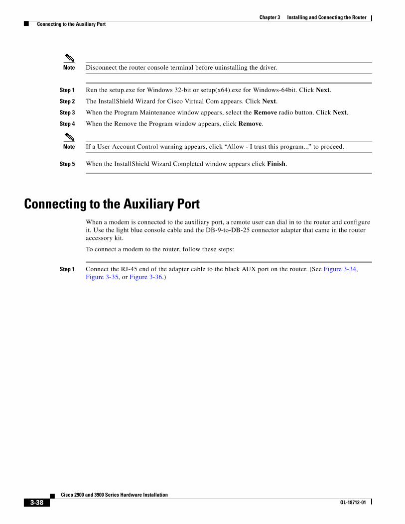
Connecting to the Auxiliary PortWhen a modem is connected to the auxiliary port, a remote user can dial in to the router and configure it. Use the light blue console cable and the DB-9-to-DB-25 connector adapter that came in the router accessory kit.
To connect a modem to the router, follow these steps:
Step 1 Connect the RJ-45 end of the adapter cable to the black AUX port on the router. (See Figure 3-34, Figure 3-35, or Figure 3-36.)
3-38Cisco 2900 and 3900 Series Hardware Installation
OL-18712-01
Chapter 3 Installing and Connecting the Router Connecting to the Auxiliary Port
Figure 3-34 Connecting a Modem to the Cisco 2901 Router
1 RJ-45 AUX port 3 RJ-45 to DB-9
2 DB-9 to DB-25 adapter 4 Modem
DO NOT REMOVE DURINGNETWORK OPERATION
DO NOT REMOVE DURINGNETWORK OPERATION
2516
04
2
34
CONSOLE
AUX
EN
1
CONSOLE
AUX
1
3-39Cisco 2900 and 3900 Series Hardware Installation
OL-18712-01
Chapter 3 Installing and Connecting the Router Connecting to the Auxiliary Port
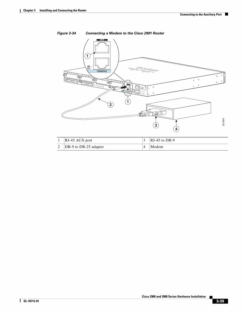
Figure 3-35 Connecting a Modem to the Cisco 2921 Router
Figure 3-36 Connecting a Modem to the Cisco 2921, 2925, 3925, and 3945 Routers
1 RJ-45 AUX port 3 RJ-45 to DB-9
2 DB-9 to DB-25 adapter 4 Modem
DO NOT REMOVE DURINGNETWORK OPERATION
DO NOT REMOVE DURINGNETWORK OPERATION
CONSOLE
AUX
2
34
1
2516
02
CONSOLE
AUX
EN
1
1 RJ-45 AUX port 3 RJ-45 to DB-9
2 DB-9 to DB-25 adapter 4 Modem
DO NOT REMOVE DURINGNETWORK OPERATION
DO NOT REMOVE DURINGNETWORK OPERATION
2516
04
2
34
CONSOLE
AUX
EN
1
CONSOLE
AUX
1
3-40Cisco 2900 and 3900 Series Hardware Installation
OL-18712-01

Chapter 3 Installing and Connecting the Router Connecting WAN, LAN, and Voice Interfaces
Step 2 Connect the DB-9 end of the console cable to the DB-9 end of the modem adapter.
Step 3 Connect the DB-25 end of the modem adapter to the modem.
Step 4 Make sure that your modem and the router auxiliary port are configured for the same transmission speed (up to 115200 bps is supported) and for mode control with data carrier detect (DCD) and data terminal ready (DTR) operations.
Connecting WAN, LAN, and Voice InterfacesThis section describes how to connect WAN, LAN, and voice interface cables. It covers the following topics:
• Ports and Cabling, page 3-43
• Connection Procedures and Precautions, page 3-44
Note One or two Ethernet cables are typically provided with the router. Additional cables and transceivers can be ordered from Cisco. For ordering information, contact customer service. For cable pinouts, see the Cisco Modular Access Router Cable Specifications document.
Warning Do not work on the system or connect or disconnect cables during periods of lightning activity. Statement 1001
Warning To avoid electric shock, do not connect safety extra-low voltage (SELV) circuits to telephone-network voltage (TNV) circuits. LAN ports contain SELV circuits, and WAN ports contain TNV circuits. Some LAN and WAN ports both use RJ-45 connectors. Use caution when connecting cables. Statement 1021
Warning Hazardous network voltages are present in WAN ports regardless of whether power to the unit is OFF or ON. To avoid electric shock, use caution when working near WAN ports. When detaching cables, detach the end away from the unit first. Statement 1026
Caution To comply with the Telcordia GR-1089 NEBS standard for electromagnetic compatibility and safety, connect Gigabit Ethernet ports using RJ-45 connectors for shielded twisted pair cable only to intra-building or unexposed wiring or cable. The intrabuilding cable must be shielded and the shield must be grounded at both ends. The intra-building port(s) of the equipment or subassembly must not be metallically connected to interfaces that connect to the OSP or its wiring. These interfaces are designed for use as intra-building interfaces only (Type 2 or Type 4 ports as described in GR-1089-CORE, Issue 4) and require isolation from the exposed OSP cabling. The addition of Primary Protectors is not sufficient protection in order to connect these interfaces metallically to OSP wiring.
Warning Never install telephone jacks in wet locations unless the jack is specifically designed for wet locations. Statement 1036
3-41Cisco 2900 and 3900 Series Hardware Installation
OL-18712-01
Chapter 3 Installing and Connecting the Router Connecting WAN, LAN, and Voice Interfaces
Warning Never touch uninsulated telephone wires or terminals unless the telephone line has been disconnected at the network interface. Statement 1037
Warning Class 1 laser product. Statement 1008
3-42Cisco 2900 and 3900 Series Hardware Installation
OL-18712-01
Chapter 3 Installing and Connecting the Router Connecting WAN, LAN, and Voice Interfaces
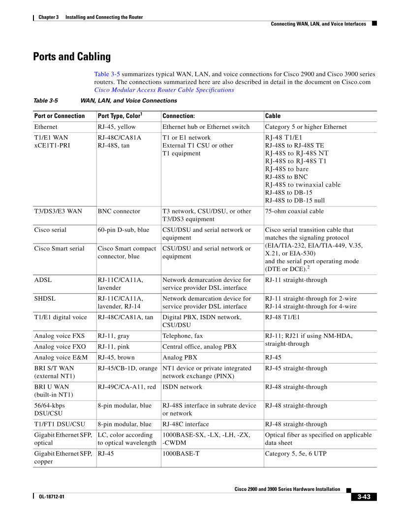
Ports and CablingTable 3-5 summarizes typical WAN, LAN, and voice connections for Cisco 2900 and Cisco 3900 series routers. The connections summarized here are also described in detail in the document on Cisco.com Cisco Modular Access Router Cable Specifications
Table 3-5 WAN, LAN, and Voice Connections
Port or Connection Port Type, Color1 Connection: Cable
Ethernet RJ-45, yellow Ethernet hub or Ethernet switch Category 5 or higher Ethernet
T1/E1 WANxCE1T1-PRI
RJ-48C/CA81ARJ-48S, tan
T1 or E1 networkExternal T1 CSU or other T1 equipment
RJ-48 T1/E1RJ-48S to RJ-48S TERJ-48S to RJ-48S NTRJ-48S to RJ-48S T1RJ-48S to bareRJ-48S to BNCRJ-48S to twinaxial cableRJ-48S to DB-15RJ-48S to DB-15 null
T3/DS3/E3 WAN BNC connector T3 network, CSU/DSU, or other T3/DS3 equipment
75-ohm coaxial cable
Cisco serial 60-pin D-sub, blue CSU/DSU and serial network or equipment
Cisco serial transition cable that matches the signaling protocol (EIA/TIA-232, EIA/TIA-449, V.35, X.21, or EIA-530) and the serial port operating mode (DTE or DCE).2
Cisco Smart serial Cisco Smart compact connector, blue
CSU/DSU and serial network or equipment
ADSL RJ-11C/CA11A, lavender
Network demarcation device for service provider DSL interface
RJ-11 straight-through
SHDSL RJ-11C/CA11A, lavender, RJ-14
Network demarcation device for service provider DSL interface
RJ-11 straight-through for 2-wireRJ-14 straight-through for 4-wire
T1/E1 digital voice RJ-48C/CA81A, tan Digital PBX, ISDN network, CSU/DSU
RJ-48 T1/E1
Analog voice FXS RJ-11, gray Telephone, fax RJ-11; RJ21 if using NM-HDA, straight-throughAnalog voice FXO RJ-11, pink Central office, analog PBX
Analog voice E&M RJ-45, brown Analog PBX RJ-45
BRI S/T WAN (external NT1)
RJ-45/CB-1D, orange NT1 device or private integrated network exchange (PINX)
RJ-45 straight-through
BRI U WAN (built-in NT1)
RJ-49C/CA-A11, red ISDN network RJ-48 straight-through
56/64-kbps DSU/CSU
8-pin modular, blue RJ-48S interface in subrate device or network
RJ-48 straight-through
T1/FT1 DSU/CSU 8-pin modular, blue RJ-48C interface RJ-48 straight-through
Gigabit Ethernet SFP, optical
LC, color according to optical wavelength
1000BASE-SX, -LX, -LH, -ZX, -CWDM
Optical fiber as specified on applicable data sheet
Gigabit Ethernet SFP, copper
RJ-45 1000BASE-T Category 5, 5e, 6 UTP
3-43Cisco 2900 and 3900 Series Hardware Installation
OL-18712-01

Chapter 3 Installing and Connecting the Router Connecting WAN, LAN, and Voice Interfaces
Connection Procedures and Precautions• Connect each WAN, LAN, and voice cable to the appropriate connector on the chassis or on a
network module or interface card.
• Position the cables carefully, so that they do not put strain on the connectors.
• Organize cables in bundles so that cables do not intertwine.
• Inspect the cables to make sure that the routing and bend radius is satisfactory. Reposition cables, if necessary.
• Install cable ties in accordance with site requirements.
For cable pinouts, see Cisco Modular Access Router Cable Specifications.
1. Cable color codes are specific to Cisco cables.
2. See the Cisco Modular Access Router Cable Specifications document for information about choosing these cables.
3-44Cisco 2900 and 3900 Series Hardware Installation
OL-18712-01