Land resources and production systems in agricultural land ...

May, 1992
A cooperative effortbetween the NorthCarolina Departmentof Environment,and Natural Resources,and the North CarolinaCooperative ExtensionService, supported bythe North CarolinaSedimentation ControlCommission
Erosion andSediment
Control
Inspector s̓ Guide

Disclaimer
The contents of this publication were prepared by the authors and should not be interpreted as necessarily representing the policies or recommendations of other referenced agencies or organizations. Additional information is available in the North Carolina Erosion and Sediment Control Planning and Design Manual, and the North Carolina Erosion and Sediment Control Field Manual.The mention of trade names, products, or companies does not constitute an endorsement.This manual is intended for periodic update. Section may be changed as practices for erosion and sedimentation control evolve.

Acknowledgments
This manual was prepared by the NCSU Water Quality Group in cooperation with the North Carolina Department of Environment, Health, and Natural Resources (DEHNR). The project was made possible by funding from the North Carolina Sedimentation Control Commission.We wish to acknowledge the roles of Charles Gardner, PE, Francis M. Nevils, Jr., PE, S. Craig Deal, PE, Stephen T. Reid, and Randy Cotten of the DEHNR, who guided the planning, development, and review of this manual.We especially acknowledge the regional engineers and the inspector-technicians from the regional offi ces for their very important input, ideas and reviews of this guide.The authors express their gratitude to the numerous reviewers in state and local government, federal agencies, and the private sector whose generous help improved the content and appearance of this manual.We would like to acknowledge Karl E. Larson, of the NCSU Department of Agricultural Communications, for design and page layout.Sandy Sullivan, graphic artist for the Water Quality Group, illustrated the manual and provided assistance in production.
Project Director and EditorJon A. Arnold Ph.D., PEWater Quality Group,Biological and AgriculturalEngineering, North CarolinaState University
Engineering/TechnicalConsultantsRobert G. Jessup, PESCS State ConservationEngineer, RetiredJoseph A. Phillips, Ph.D.Professor Emeritus,Department of SoilScience, CooperativeExtension Service,North Carolina StateUniversity

Table of Contents
1 The Inspector and the Law Overview of the Law and Rules, program structure and the inspector s̓
duties under the Law and to the public.
2 Erosion and Sediment Control Principles Scheduling, protecting the land surface, keeping runoff velocities low,
capturing sediment near the source, inspection and maintenance.
3 Inspecting Sites How to prepare for an inspection, preconstruction conferences, methods
for inspecting sites, causes of noncompliance.
4 Inspecting Vegetation Used for Erosion Control Proper selection, preparation and use of vegetation.
5 Inspecting Erosion and Sediment Control Practices Ground Covers ............................................................................................ 5.2
Entrances and Exits .............................................................................. 5.4Runoff Control — Diversions ............................................................... 5.5Runoff Conveyances — Channels, Drains and Chutes ......................... 5.6Outlet Protection ................................................................................... 5.7Inlet Protection ..................................................................................... 5.8Sediment Traps and Barriers .............................................................. 5.10Stream Crossings ................................................................................ 5.12Buffer Zones ........................................................................................ 5.13Maintenance ....................................................................................... 5.14
6 AppendicesA. Human Relations ............................................................................. 6.1
Dealing with Angry People .............................................................. 6.1Being the Bearer of Bad News ......................................................... 6.3
B. Soil and Vegetation .......................................................................... 6.6C. Water and Runoff Management ....................................................... 6.9
Concrete and Corrugated Metal Pipe Full Flow Values ................. 6.9Problems with Improperly Installed Channels .............................. 6.10
D. Erosion and Sedimentation ............................................................ 6.11Damages from Erosion and Sedimentation ................................... 6.11Estimating and Measuring Erosion and Sediment Volumes .......... 6.12
E. Tools of the Inspector..................................................................... 6.13F. Conversions, Tables and Reference Information ........................... 6.14
Slope Measurement ........................................................................ 6.15Soil Textural Classifi cation ............................................................ 6.16Crushed Stone Reference ............................................................... 6.17Riprap and Erosion Control Stone, NC DOT Sizes ....................... 6.19Crushed Stone Sizes and Uses, NC DOT Sizes .............................. 6.20Notes About Crushed Stone Usedfor Erosion and Sediment Control ................................................. 6.21
G. Construction Plan and Aerial Photos ............................................ 6.22

1


1.1
The Sedimentation Pollution Control Act of 1973 authorized the program and set the standards for erosion and sediment control in North Carolina. This chapter discusses the program structure and how the law is carried out. Refer to the Act and the Rules governing Sedimentation Control, Title 15A NCAC Chapter 4, for more details.
The Inspector andthe Law
1
The SedimentationPollution Control Act
The North Carolina Erosion and Sedimentation Control Program was created by the Sedimentation Pollution Control Act of 1973. This legislation authorizes the North Carolina Department of Environment, Health and Natural Resources to provide staff to the Sedimentation Control Commission to operate a program to limit erosion and sediment from land-disturbing activities. It allows local governments, state agencies and federal agencies to conduct their own erosion and sedimentation control programs with the approval of the state. The Act does not apply to forestry using Best Management Practices, agriculture or mining activities.The Act is performance-oriented; that is, the measures used at a construction site must be effective in controlling erosion and preventing off-site sedimentation for the site to be in compliance. Following an approved plan and installing the control measures may not be enough. If erosion and sediment damage occurs, the person responsible must install additional measures to correct the problem.The law is fl exible, allowing the responsible parties to determine the most economical, effective means for erosion control. This encourages the use of innovative techniques and specifi cally designed erosion control systems. The law emphasizes that the system must control accelerated erosion and prevent off-site sedimentation.
PLANS GROUND COVERS
BUFFER ZONESSTABILITY
SEDIMENTCONTROL ACT

1
The Act contains four mandatory standards to control erosion and sedimentation.1. Prior to beginning any land-disturbing activity, a plan must be approved for sites on which more than one acre on a tract will be disturbed. This plan must be submitted 30 days before the land-disturbing activity is to begin. If the Land Quality Section has not acted on plan by the end of the 30 day period, the plan is automatically considered to be approved under the law.2. Buffer zones must be provided along all natural watercourses and lakes. These buffer zones must retain all visible sediment within the fi rst 25 percent of the buffer zone nearest the disturbed area. Along trout streams, the buffer zone must be a minimum of 25 feet in width or of suffi cient width to retain all visible sediment within the fi rst 25 percent, whichever is greater.3. All disturbed areas must be able to be stabilized by vegetation or other suitable erosion control methods. These areas must be stabilized within 30 working days after completing any phase of grading.4. All land-disturbing activities on a tract comprising more than one acre, when more than one acre on a tract is disturbed, must retain all sediment on-site. In addition, the responsibile party must provide permanent ground covers within 30 working days or 120 calendar days, whichever is shorter, after completion of construction.
The North Carolina Sedimentation Control Commission is the fi nal authority for the Erosion and Sedimentation Control Program. The commission consists of volunteers, appointed by the Governor, who represent a wide range of interests in erosion and sedimentation. The commission meets every 90 days to conduct business and review the overall program.
GS 113A-54(d)(4), 113A-54.1(a), 113A-57(4)
GS 113A-57(1)
GS 113A-57(2)
GS 113A-57(3)
Program Authority
Figure 1.1 Erosion andSediment Control Program
Structure
1.2
North Carolina SedimentationControl Commission
Land Quality Section(Department of Environment,
Health, and Natural Resources)
RegionalOffi ce
LocalPrograms
State AgencyPrograms

The Land Quality Section, Division of Land Resources, Department of Environment, Health, and Natural Resources, administers the Erosion and Sedimentation Control Program. The Land Quality Section operates a central offi ce in Raleigh and seven regional offi ces across the state.Work in the fi eld is administered by the regional offi ces and by approved local and state agencies. Local and state agencies have their own staff for the implementation of the programs, including inspections.
The Program operates by Rules given in Section 15A of the North Carolina Administrative Code.1 These Rules, commonly called regulations, specify the requirements and standards on construction sites that must be met.The Rules are usually developed by the commission through its Technical Advisory Committee with support from the Land Quality Section staff. Public hearing are held on all proposed Rules, which are then presented to the Sedimentation Control Commission for approval. Once approved by the Commission, the Rules become law.The Rules interpret and defi ne the intent of the act and therefore are performance oriented. The intent of the Rules is to prevent accelerated erosion and to control sedimentation through the following procedures:■ Identifying critical areas;
■ Limiting exposed areas;
■ Limiting time of exposure;
■ Controlling surface water;
■ Controlling sedimentation; and
■ Managing storm water runoff.The use of these procedures to achieve compliance with the Rules is discussed in Chapters 2-5.The inspector should be familiar with the defi nitions of the terms used in the Rules and in the laws governing erosion and sedimentation.2
Remember that the Act and the Rules are performance-based. If the measures used at a site are not controlling erosion and sedimentation, the person responsible for the site must install additional measures. The inspector is the key in making this kind of performance-based law work because he is the fi rst person to recognize performance failures and report the problems.
The inspectorʼs job is to:■ Determine that an erosion and sediment control plan for the site has been approved;
■ Determine that all specifi ed practices have been installed and are being maintained according to the plan
■ Determine that off-site sedimentation is being prevented.
115A NCAC 04A—E.5002The defi nitions are listed in the Rules under 15A NCAC NCAC 04A.0005 and in the Act.
1.3
SedimentationControl Rules
The Inspector andthe Public
The Inspector and the Law

If the inspector fi nds defi ciencies, appropriate action must be taken to attain compliance.The inspector must have technical expertise in erosion control. In addition, in order to achieve full compliance, the inspector must be able to deal effectively with people. For example, disputes sometimes arise about a site violation. The person responsible for the site may disagree with your assessment of the site. Neighboring landowners may be upset and demand that corrective action be taken immediately. At times like these, it is easy to become overly emotional. No matter what the situation, inspectors need to carry out their responsibilities in a professional manner and in accordance with the rules. Inspectors must maintain their integrity if they are to do the job well and be respected as professionals.Inspectors need to know how to deal with people. See Appendix A for guidelines in interacting with people who are angry or upset. The guidelines can be a big help in your job.In dealing with the public it is most important to follow proper legal procedures and to remain courteous and fair. If you fail to follow proper legal procedures you may not be able to prosecute a violator. By showing courtesy and fairness, you encourage mutual respect among all persons involved. Parties responsible for construction sites are less likely to violate the act if they see the inspector as a competent professional.Remember that the goal of the program is to prevent accelerated erosion and off-site damage from sediment. As the inspector, you are the fi rst person to determine if the performance standards and intent of the act are met. You are the key person ensuring that construction sites are evaluated fairly and consistently and that the responsible party keeps the site in compliance.
Any activity that disturbs land, except agriculture, mining and forestry using Best Management Procedures, is subject to the Sedimentation Pollution Control Act and may require inspection. Even a private homeowner installing a driveway must comply with the law. However, most small projects cause few problems and do not normally require the attention of an inspector.
Examples of sites that are usually inspected include:
■ all sizes of commercial and industrial developments;
■ housing subdivisions;
■ shopping centers;
■ public buildings;
■ utility construction;
■ highway construction and maintenance; and
■ recreational facilities.Before construction begins, an approved plan must be developed for any site where more than one acre of land on a tract is to be disturbed. You can fi nd help in determining the size of a project from the tax assessorʼs offi ce, topographic maps, and survey plats of the site.
1.4
Sites Subject to Law
1

Some construction sites require extra care to ensure that they are in compliance, especially those near or crossing watercourses, trout waters or high-quality waters. These sites must meet more stringent requirements for the user of buffer zones and for the general protection of water. High-quality water zones in coastal counties mean those areas within 575 feet of the High Quality Water. For the rest of the state, High Quality Water zones include those areas within one mile that drain to the High Quality Water. (See defi nitions 24, 25 and 27 of the rules, 15A NCAC 04A.0005.)As the inspector on the site, you play a central role in providing details of violations and subsequent corrections. The policy for handling violations depends on whether the state or a local government has jurisdiction. The policy for state programs may be obtained from the Sedimentation Control Commission. Violation policies for local programs or state agencies may be obtained from the appropriate offi ce. These policies outline the actions that are required under each program to bring the site into compliance. We recommend that you insert a copy of the proper policy for your program into this guide for quick and easy reference.The inspection records that you write are the basis for hearings and assessing fi nes, You are the fi rst person to determine whether the measures on the site are preforming properly; thus you are the fi rst link in enforcing the erosion and sedimentation Rules. Inspectors are often called to appear at hearings as witnesses to document a violation. For information on hearing procedures and on how to conduct yourself as a witness, refer to the Enforcement Manual, available from the Land Quality Section.You should write a report for every inspection of a site. When writing your inspection report, remember that it is a legal document. Your report must be written accurately, consistently and in clear and concise language. Report all violations observed each time you visit a site even if you have reported some of them on previous visits, Always write inspection reports while you are on the site so that you will not forget items and can recheck conditions if you have doubts.Field notes are very effective in hearings. They should be organized, thorough, concise and legible. Make a habit of taking organized, well-written notes. It will pay off the next time you are in court.
The Inspector and the Law
1.5
Handling Violations

1.6

2


Accelerated erosion and sedimentation can be controlled by following fi ve basic principles.Erosion control practices are simple, effective and inexpensive if implemented before a problem occurs. The key is to install a system that makes all erosion and sediment control practices work together.
Erosion and SedimentControl Principles
2
Controlling Erosionand Sedimentation
Accelerated erosion takes place when wind, rainfall and runoff act upon disturbed soil. Normal construction activities, such as clearing and grading, leave the soil bare and compacted. With no protective cover, soil particles are easily washed or blown away. Grading smooths and usually compacts the soil, reducing the amount of rainfall that infi ltrates into the ground. Because less rainfall is absorbed, the volume of runoff is increased. The smooth, compacted surface further increases the velocity of the runoff. These conditions lead to accelerated erosion on the construction site and may cause off-site sedimentation, streambank sloughing and fl ooding problems.It is much less expensive and less damaging to the environment to prevent erosion and sedimentation than to clean up after it has happened. Carefully following these principles of erosion and sediment control will help in preventing environmental damage:■ Coordinate sediment control with construction activities;
■ Protect the land surface from erosion;
■ Manage runoff and keep velocities low;
2.1
EROSIONCONTROL
MANAGERUNOFF
PROTECTLAND SURFACE
COORDINATECONSTRUCTION
INSPECT ANDMAINTAIN
CAPTURESEDIMENT

■ Capture sediment near the source; and
■ Inspect and maintain the erosion and sediment control system.
As an erosion and sediment control inspector, you should be familiar with these principles and know how to apply them on construction sites.
The key to effi cient and cost-effective erosion control is to plan construction activities in phases to reduce the erosion potential of the site. Each phase exposes only small areas of land, making it much easier to control erosion than if the entire site were exposed at once.Erosion and sedimentation can be controlled most effectively by coordinating the construction schedule with the installation of erosion control measures. Before any site disturbance occurs, sediment traps, basins and diversions should be in place to control runoff and catch sediment. Graded areas should be seeded and mulched immediately, according to the schedule, rather than waiting until all the grading has been completed. A well-planned construction entrance with stabilized construction roads can prevent major erosion and sediment problems, complaints from neighbors and future aggravations.
Erosion can be greatly reduced by simply covering the soil to protect it from the effects of rainfall, runoff and wind. By paying attention to the following principles, erosion can be limited and the cost of maintaining sediment control devices reduced.■ Construction activities should be scheduled to reduce the duration of exposure of bare soil.
■ The size of the disturbed area should be kept as small as practical. The construction schedule should be planned to limit the area graded at any one time. Buffers should be left around all working areas. No areas outside the designated work area should be disturbed.
■ Runoff should be diverted away from slopes to be graded.
■ Construction roads, parking areas and the construction entrance should be stabilized immediately. Equipment operators should use the designated routes to limit ruts, erosion and tracking of sediment and debris from the site.
■ All streams, lakes and natural watercourses should be protected by buffers. All drainage channels should be stabilized as soon as they are constructed.
■ Graded surfaces should be covered with temporary vegetation and mulch when work is interrupted for extended period.
Measures to protect the soil surface are described in the following sections of the North Carolina Erosion and Sediment Control Planning and Design Manual:
■ Temporary Seeding, 6.10;
■ Permanent Seeding, 6.11;
■ Mulching, 6.14;
■ Riprap, 6.15;
■ Temporary Gravel Construction Entrance/Exit, 6.06;
Scheduling
Protecting the LandSurface
2
2.2

Erosion and Sediment Control Principles
■ Construction Road Stabilization, 6.80;
■ Sodding, 6.12;
■ Trees, Shrubs, Vines and Ground Covers, 6.13;
■ Temporary Diversions, 6.20;
■ Grass-lined Channels, 6.30;
■ Dust Control, 6.84;
■ Runoff Control Measures, 6.20-6.23;
■ Runoff Conveyance Measures, 6.30-6.33; and
■ Stream Protection Measure, 6.70-6.73
Erosion is greatly increased if runoff is allowed to fl ow at high velocities.Control measures, installed properly and at the proper times, keep runoff velocities low and prevent erosion. Where practical, measures should be takento divert water from fl owing onto the site from outside the area. Energydissipators should be used to reduce the fl ow velocity of water leaving the site. Certain areas, such as constructed fi ll slopes and newly cut channels, need special attention. The following practices will help control runoff velocities.■ The work area should be protected from off-site water with perimeter dikes or temporary diversions.
■ Runoff water should be diverted into stabilized channels with stable outlets.
■ Runoff from disturbed areas should be diverted to sediment traps or basins.
■ Where practical, runoff from undisturbed areas should be diverted around sediment basins and traps to stable areas and protected outlets. This reduces the volume of water that fl ows into the sediment basins and traps, increasing their effi ciency and reducing their costs
■ Long slopes must be broken up with temporary or permanent diversions to prevent the buildup of runoff and reduce runoff velocity.
■ The permanent storm water drainage system should be installed during early stages of construction and used to manage runoff. All inlets should be protected with appropriate measures to prevent sediment from entering the storm drains.
■ Critical construction areas should be protected from unexpected rain by installing temporary diversions at the end of each work day.
Practices for controlling runoff velocities are discussed in the following sectionsof the North Carolina Erosion and Sediment Control Planning and Design Manual:
■ Temporary Diversions, 6.20;
■ Diversion Dike (Perimeter Protection), 6.22;
■ Permanent Diversions, 6.21;
■ Right-of-Way Diversions (Water Bars), 6.23;
■ Level Spreader, 6.40;
■ Outlet Stabilization Structure, 6.41;
Keeping RunoffVelocities Low
2.3

■ Temporary Slope Drains, 6.32;
■ Riprap, 6.15
■ Grass-lined Channels, 6.30; and
■ Riprap-lined Channels, 6.31;
Generally it is easier, safer and more practical to capture sediment near the source than to install a single large sedimentation basin and try to capture the sediment from an entire site. A few small, well-maintained sediment traps or barriers properly located at the edges of the graded area will control sediment better and take up less space than a single large sediment basin farther away. Also, large sediment basins present a greater hazard if they fail.Remember that sediment traps, sediment basins and barriers such as silt fences remove sediment by pooling water and allowing the sediment to settle out. Silt fences and rock structures do not fi lter the water effectively because they clog too easily. These fences and structures are used to form a pool where the water velocity is slowed, allowing the sediment to settle.The other key to capturing sediment is to inspect and maintain the devices frequently. The pools created by these devices will fi ll with sediment. This sediment must be removed so the device will have adequate capacity for the next rainfall. Occasionally the overfl ow structure will need to be repaired or rebuilt. The devices should be inspected frequently to ensure they are functioning properly.Adequate access to the sediment control devices may not be provided for in the plans or may be blocked by construction. If the contractor cannot get in to clean out the trapped sediment and make repairs, violations may occur. All sediment control devices must be accessible so that cleaning, inspections and maintenance can be performed.
Erosion and sediment control measures, practices and devices should work as a system—all the components should work together to prevent erosion and off-site sediment damage. Regular inspections and maintenance of all devices are necessary for the system to work effectively.Lack of maintenance is the most common reason for failures. Contractors and the responsible parties cannot know that a device needs maintenance unless they inspect it regularly. A low point in a dike or diversion can lead to the formation of a major gully after the next rain. A collapsed sediment fence or inadequate inlet protection device and allow large amounts of sediment to move off-site. The failure of a large sediment basin could have severe consequences.The erosion control inspector must insist that contractors and the responsible parties regularly inspect erosion and sediment control measures. The owners are responsible for ensuring that all erosion and sediment control measures are frequently inspected and repaired.
2.4
Capturing SedimentNear the Source
Inspection andMaintenance
2

3


Inspections don t̓ “just happen;” A lot of planning and preparation go into a proper and thorough inspection. Inspectors need to review construction plans, attend preconstruction conferences and be knowledgeable of the law and standards. Knowing why a site is or is not in compliance is a key part of the inspector s̓ duty.
Inspecting Sites
3
The Inspection An erosion control plan is designed to control erosion; however, components of the plan may fail or the responsible party may not adhere to the plan. For these reasons, the Sedimentation Pollution Control Act of 1973 includes provisions for the inspection of sites where land-disturbing activities are taking place. As the inspector of these sites, your job is;■ to be certain that all erosion and sediment control measures in the approved plan have been properly installed and maintained;
■ the erosion is being controlled; and
■ that off-site sedimentation is being prevented.
It takes time to learn how to inspect a construction site properly. Project sites are often large and can have many land-disturbing activities occurring at any one time, which can be confusing. Also, there are many considerations to keep inmind while conducting the inspection. You must be familiar with the law, therules and many erosion and sedimentation control practices. With some experience,
3.1
INSPECTIONSEDIMENTATIONCONTROL ACT
REVIEWOF PLAN
PRACTICEINSTALLATION
COMPLIANCE
PERFORMANCE PRECONSTRUCTIONCONFERENCE

however, you will soon feel comfortable about making an offi cial erosion control inspection. This guide will help by providing some ideas on how to make a thorough inspection.A proper inspection requires planning and a systematic approach. With careful preparation, you can carry out your duty and work cooperatively with the responsible parties and the contractors so that all those involved can do their jobs effi ciently.
The fi rst step in inspecting a project is to review plans when fi rst submitted. This review will alert you to potential problems at the site and weaknesses in the erosion and sedimentation control system design. Make a list of comments for the engineer who will approve the plan so that he can benefi t from your review. By working together, you and the engineer will complement one anotherʼs skills, making for a sound review and approval process.While at your offi ce, look for the following items in the plan. (There are other items that you may want to include as you gain more experience.)■ Check contour maps and available aerial photos to see how the water fl ows through the site. Note where water enters and leaves the site. Determine the direction of fl ow in the general area and in the watershed where the project is located.
■ Note if the site borders a sensitive area such as a stream or high quality water body. The perimeter should be especially well protected against off-site sedimentation.
■ Pay particular attention to critical areas such as steep cut-and-fi ll slopes, stream crossings, channels, outlets of pipes and diversions, construction access routes and highly erodible soils.
■ Look for adequate access to and space to maintain erosion and sediment control measures.
IN THE OFFICEAERIAL PHOTOS PLAN
CRITICAL AREAS
TOPOGRAPHY HYDRAULICS
Preparing for anInspection
3
3.2

■ Make sure that the plan provides an installation sequence for measures to control erosion and sediment, with measures for one phase being installed before grading of the next phase begins.
■ Study the construction schedule to determine whether long periods of time exist between phases of construction. If so, temporary seeding or other temporary soil stabilization may be required.
■ Check to make sure that the plan requires all surfaces to be stabilized as soon as possible after completion of the project and within the mandatory 30 working days or 120 calendar days (15 days and 60 days if in a High Quality Waters Zone). Temporary and permanent seeding should also be specifi ed.
■ Remember that when the contractor is fi nished, the entire site should be stabilized—no accelerated erosion and no off-site sedimentation should occur.
■ Note if the measures are designed for the 10-year storm. Some measures should provide for safe bypass of fl ows greater than the 10-year storm. High Quality Waters Zones require design and safe bypass for the 25-year storm.
■ Be sure that the perimeter of the site is protected to prevent off-site sedimentation and keep off-site runoff from fl owing across highly erodible areas during construction.
■ Make sure that maintenance plans are adequate and the contractorʼs procedure in monitoring the performance of control measures is specifi ed. For example, it should be clear whether the contractor or someone else is to do the inspection and maintenance.
■ Note any proposed borrow or waste areas and proposed measures for controlling erosion and sedimentation there.
■ Watch for existing areas that may not be in compliance, such as old highways and abandoned railroad rights-of-way. Those parties responsible for the land disturbance are responsible for erosion control even if ownership of the property has changed.
■ Check tree-cutting operations to ensure compliance with Forest Practice Guidelines Related to Water Quality (Best Management Practices, or BMPʼs).
■ Make a list of the specifi c items of the plan that you want to inspect closely when you get to the site. This list can speed your inspection and remind you to check certain important points.
■ Determine the owner(s) of the site itself and of the adjoining property. Though this sometimes may be diffi cult to determine, you can get useful information from the county register of deeds or tax records.
Reviewing the erosion and sedimentation control plan should provide you with a solid grasp of the proposed project. From the review you can identify parts of the erosion control system that may need to be strengthened and parts that should be watched carefully to see if the performance requirement is met. Your experience in the fi eld and in the geographical area will provide valuable assistance in the approval or revision of the submitted plan.
Inspectors must also be familiar with the construction plans. In Appendix G you will fi nd two views of a highway project. The upper view is an aerial photo of a construction site. Below the aerial phoyo is the corresponding construction plan of the site. Compare the two views to fi nd out if the measures called for on the plans have been installed at the site and if they are in the proper locations. The
3.3
Inspecting Sites

captions will help you see the control measures. Study these plans, paying attention to the highlighted items, so that you become better able to readconstruction plans.
The ability to read aerial photos is important because many construction projects now use aerial photos on which to draw the construction plans. It will take some practice to be able to recognize ordinary objects from the air.
Many experienced people have found that aerial photos and topographic maps can help greatly in determining the effects of a project on the surrounding area. Aerial photos can be obtained from the local ASCS (Agricultural Stabilization and Conservation Service) offi ce or the state Department of Transportation (DOT). The 1:660 scale is usually used. The USGS (United States Geological Survey) is a good source for topographic maps. These maps are drawn on a scale of 1:24,000.
Reviewing the construction plan provides information needed for the next step of the inspection process, the preconstruction conference. Use the suggestions below to ensure that you are fully prepared for the conference.
A preconstruction conference is one of the most valuable vehicles by which you can address and divert many potential erosion and sedimentation problems before they become catastrophes. For complex projects, a preconstruction conference should be mandatory. This conference provides an opportunity for you to meet face-to-face with the responsible party and the contractor. In this way, you establish the expectations for the project and start a good working relationship with the job superintendent. While holding the conference, keep the following suggestions in mind:
■ Clarify the objectives of erosion and sediment control and inform all parties about the specifi c requirements for compliance in this project. Also, discuss the inspection procedures and establish communications and scheduling so that everyone knows what will be happening during the project.
■ Designate a contact person for communicating concerns about erosion control. This will make future contacts much easier.
PRECONSTRUCTIONCONFERENCECOMMUNICATIONS EXPECTATIONS
PROCEDURESFOR CHANGES
LOOKING OVERTHE SITE
PRECONSTRUCTIONCONFERENCES
3
3.4

■ Be sure that all parties review a copy of the approved erosion and sediment control plan so that they know what is expected and are prepared to initiate the plan. An approved copy of the plan must be available on the site at all times.
■ Inform the responsible party and the contractor that the program is performance oriented and that the plan may need to be changed during the course of construction. Inform all parties about procedures for changing the plans. Remember that all revisions to erosion and sediment control plans must be approved before they are put into effect.
■ Try to hold the conference on the site. There, the group can walk the site and compare the plans to see if the measures are appropriate, are located properly, and can be maintained once installed. Note areas where sediment from the sediment traps and basins can be placed and stabilized when the devices are cleaned. The site is also the best place to determine if adequate access will be available to maintain the erosion control measures.
■ Discuss the scheduling of clearing and grading. Emphasize that sediment control measures should be installed before the actual grading begins in order to capture sediment as it is generated. Be sure that the schedule allows for stabilizing surfaces with temporary and permanent measures during and between phases of grading and construction.
■ Discuss the maintenance requirements so that the responsible party and the contractor know who is responsible for inspecting, cleaning and repairing the measures. Regular inspection and maintenance may need to be supplemented with extra work if there is a large storm.
■ Establish open communications at the preconstruction conference; this pro-vides a good foundation for your relationship with the responsible parties during the project.
■ Take the time to review the plans thoroughly before you go to the site, even if you have already reviewed them when they were fi rst submitted.
■ Outline your approach for each inspection. It is necessary to know in detail the erosion control system and why each measure is specifi ed.
■ Always take a copy of the approved plans with you to the site for quickreferral.
■ Always bring the project fi le and necessary reporting forms.
3.5
INSPECTIONPREPARATIONREVIEW PLAN CARRY PLAN
WITH YOU
OUTLINE
Inspecting Sites
Before you Leavethe Offi ce

ON SITEEROSION
CONTROLLEDOFF SITE
SEDIMENTATION
INSTALLED ASON PLAN
WALKINGTHE SITE
FIELD NOTES
3
At the construction site, ask yourself the following four questions:
(1) Is the erosion and sediment control system installed as shown on the approved plans?
(2) Is erosion being controlled on the site? and
(3) Is sediment being contained on the site?
(4) Are the four mandatory requirements of the Sedimentation Control Act being met?If the answer to all of these questions if YES, then the site is in compliance. File an inspection report stating that the site is in compliance and take fi eld notes to support the inspection report. It is a good idea to keep track of the sites where the erosion and sedimentation control plan works well so that you can show others an example of a good site.If the answer to any of the above questions is NO, then the site is not in compliance. File an inspection report listing the items that are not in compliance. Your fi eld notes should describe precisely the noncompliance and its location. Remember that others may need to use your fi eld notes, so make them readable and understandable.The following points will help you in checking for compliance.■ Carry a set of the approved plans to the site for your reference. They are necessary to determine what measures make up the erosion control system and how they are to be installed and maintained.
■ Take detailed, orderly fi eld notes as you do the inspection. In the long run, this procedure will save you time and possibly a second trip to the site. Be sure that your notes are neat, concise and complete. (Remember, your notes may be needed as evidence in court.)
■ Check in with the job superintendent when you arrive so that the contractor knows who you are and what you are doing. When possible, schedule appointments so that the contractor and responsible party know when to expect you.
■ Walk the perimeter of the site on your fi rst inspection. This procedure will give you a good idea of the terrain and will alert you to any problems occurring from off-site water and off-site sedimentation
Inspecting the Site
3.6

Inspecting Sites
■ You may want to start your inspection from the lowest point at the perimeter and work your way upstream. This helps to make you aware of the amount of sediment leaving the site and can help you in locating its source.
■ If sediment is fl owing off the site, go far enough downstream to see the extent of the damage. In these situations, it is very important to document the damage. Make an estimate of the sediment volume. Photos and videotapes make very good evidence. Be sure to write the time, date and other items in your notes and on the inspection report.
■ Bring necessary tools to measure the devices and disturbed areas in the fi eld. Be sure that basins and traps are fi xed according to the plans, channels and diversions have the proper grade, and contributing areas for the control devices are no larger than those used in the design.
■ Pay particular attention to the maintenance of erosion and sediment control measures. All measures require regular maintenance and may require special attention after severe storms.
■ Keep in mind that when certain structural measures fail from improper installation or maintenance, more off-site sediment damage may occur than if the device had not been installed.
■ Always fi ll out an inspection report for each trip to a site while you are still at the site. The pertinent inspection points are still fresh in your mind and you can easily re-check items that may be in question.
3.7
When you find a site that is not in compliance, it is important to determine why.By determining the cause(s), solutions become more apparent.
Problems of erosion and sediment control on sites fall into three categories:
1. The responsible party has not made efforts to comply with the law;
2. There are design errors in the erosion control system or the site conditions have changed; or
3. The installation or maintenance of a measure is faulty or inadequate.
Noncompliance in the first category is easy to spot. The responsible party may believe that the project does not come under the jurisdiction of the law or may
Causes of Noncompliance
VIOLATIONSNO EFFORTTO COMPLY
DESIGN ERROR/OVERSIGHT
FAULTYINSTALLATION
LACK OF MAINTENANCE
Little or No Effortto Comply

intentionally disregard the provisions of the law. Quite often these sites are found by inspectors while driving by. Therefore, be observant in your territory.
Once you have found a noncomplying site, inform the responsible party that compliance is mandatory by law. On the inspection report, note that the responsible party has been informed of the law and list the items that are not in compliance.
These are some of the causes of noncompliance within this category:
■ not submitting a plan;
■ starting work without an approved plan; or
■ failing to follow the approved plan.
Violations and failures may occur because the design was inadequate or the site conditions have changed since the plan was prepared. In this case, the plan needs to be revised and approved. The inspection report should note all items of non-compliance and the need for a revised plan.
Compare the original design in the plan to conditions in the fi eld. Look for changes in the site, conditions and construction plan. Ask yourself the following questions when checking for violations caused by design errors and changes.
■ Are the planned measures retaining the sediment on the site?
■ Are there modifi cations to the plan? Have they been approved?
■ Are ground covers adequate for the slope and orientation of the areas to be protected? Is the slope too steep for the ground cover chosen?
■ Is the perimeter protected, given the conditions at the site?
■ Do the measures with impoundments have a safe bypass installed for storms larger than the 10-year storm?
■ Have the contributing drainage areas changed signifi cantly, thereby potentially overloading the control measures? Are additional control measures needed?
■ Is dust control needed?
■ Is the planned and ongoing maintenance adequate for the existing conditions?
Most noncompliance occurs because measures were not installed correctly or maintained properly, or both. Determining the reasons why the measures are failing requires technical knowledge about the devices and how to construct them properly.
In the following two chapters, you will fi nd ideas on how to inspect erosion control devices and what to look for in their construction. Chapter 4 presents information on inspecting vegetation used for erosion control and Chapter 5 presents information on inspecting erosion control practices. These practices are listed in the same order as they appear in the North Carolina Erosion and Sediment Control Planning and Design Manual and the North Carolina Erosion and Sediment Control Field Manual. The references in the sidebars direct you to specifi c sections of the Design Manual and the Field Manual for more detailed information.
3.8
3
Inadequate Design or Changes in Site
Conditions
Faulty Installation and/orPoor Maintenance

4


More area is protected from erosion with vegeta-tion than with any other erosion control means. Knowing how to choose and establish the prop-er vegetation can prevent soil loss and sediment problems.
Inspecting VegetationUsed for Erosion
Control
4
Vegetation forErosion Control
Vegetation cover is the principal means used to stabilize soil surfaces. With the selection of the proper species and appropriate maintenance, vegetative cover provides inexpensive, long-term protection with moderate maintenance. Construction projects present a wide range of conditions for vegetation. This chapter describes what to look for when vegetation is used for short and long-term erosion control.
A vegetative plan is one of the keys to a well-executed project. An effective plan specifi es the appropriate plants for each disturbed area, describes proper soil preparation methods and indicates when to plant. Vegetation should be established as soon as possible after grading. Planting should be coordinated with construction so that areas do not remain uncovered, thus producing unnecessary amounts of runoff and sediment.
Vegetation works well only if the plant species selected suits the climate, soil, and the intended use for the area. Remember that at certain times of the year or under special conditions it may be necessary to use temporary vegetation before establishing permanent vegetation. Ask these questions when you inspect sites using vegetation for erosion control.
Is the plant type appropriate for the soil and the slope?
■ Plants must have fertile, well-prepared soils to grow properly, a requirement rarely met on a graded slope.
VEGETATION
SEEDBEDPREPARATION
SITE CONDITIONS
MAINTENANCE
MULCHING
Consider the Site andIts Intended Uses
4.1

4
■ Heavy, dense subsoils may be too infertile to support certain plants.
■ Graded slopes may be too steep or too rocky to prepare adequate seedbeds.
■ Steep slopes may need to be sodded or covered with riprap or concrete.
Is the plant properly chosen, given the climate and orientation for the area?
You may want to review the following sections in the North Carolina Erosion and Sediment Control Planning and Design Manual:
■ Temporary Seeding, (6.10);
■ Permanent Seeding, (6.11);
■ Sodding, (6.12); and
■ Trees, Shrubs, Vines and Ground Covers, (6.13).
Is the vegetated area being maintained?
■ Frequently the degree of maintenance required to keep a certain type of plant growing is overlooked. The responsible party must provide higher maintenance for some ornamental shrubs and grasses.
■ Also, see if the maintenance crews can reach the planted area to provide the necessary care.
■ Is the area subject to high velocity fl ow? Some areas such as channels and steep slopes may require sod, riprap or concrete linings to prevent erosion.
Graded areas are usually compacted and have little topsoil left when planting is started. Lime and fertilizer must be properly incorporated into the soil to establish an adequate seedbed for vegetative cover. If practical, the soil should be tested so that the proper amounts of lime and fertilizer can be added.
Check the following points to determine if the vegetation will be adequate.
■ Slopes that have been graded are too compacted and smooth to establish plants. It is necessary to apply fertilizer and lime, prepare a proper seedbed and roughen the surface to provide required nutrients and adequate rooting depth.
■ Keep in mind the essentials for plant growth; an adequate supply of nutrients, water and air in the root zone. These conditions are frequently lacking in graded soils. Therefore, fertilizer and lime must be added and incorporated to a depth of 4 or more inches by chiseling, plowing or roto-tilling. This preparation also enhances water and air infi ltration to the root zone.
Seeded areas should be mulched to protect and help establish erosion control vegetation. Mulching holds the seed and fertilizer in place, protects the soil, and conserves moisture. Mulching also encourages rapid seed germination by preventing soil crusting and insulates the soil against rapid temperature changes. The following points will help you determine if mulching is adequate.
■ Look for a proper thickness for thick mulch. Few areas can develop a strong growth of vegetation without mulching, and mulches are often too thin to be of much help. See the Planning and Design Manual section on mulching (6.14) for more information.
Check SeedbedPreparation
Check for ProperMulching
4.2
■ Mulch needs to be well-anchored to work properly. This requirement is often overlooked, causing many failures and much added expense for re-seeding. On fl atter slopes, mulches can be tacked by spraying on tacking agents that bind the mulch, preventing it from being washed or blown away. Crimping also works well on fl atter slopes and level areas.
■ For steeper slopes mulches should be overlaid with netting. Mats can also be used. Netting and mats should be anchored with long staples at the proper spacing to provide the best resistance to washing. Thicker and more durable mats should be used on steep slopes, areas that are exposed to high-velocity fl ows, and areas where vegetation needs more help to become established.
The key to an adequate vegetative cover that will result in good erosion control is maintenance. For vegetation, seeding, and the early stages of plant growth are especially critical. The inspector must ensure that the vegetation is protected to allow the best germination and strongest growth. Even after the vegetation has emerged, mulches and mats must be maintained to prevent washing during the next rain.
Watch for areas where the mulch is too light—the mulch can blow away or wash away in the next rain. The owner/developer must have new mulch applied and must anchor it to prevent washing.
Damage to seeded areas usually happens where the mulch is improperly anchored. These areas will require immediate repair. The responsible party should fi ll the eroded area if needed, apply new seed, lime, and fertilizer, and apply an adequate layer of mulch that is well-anchored. If the area is in a zone where the erosion potential is high or if the practice called for in the plans is inadequate, the responsible person may need to use a heavier mat to provide more protection for the vegetation.
Look for a means of access to the vegetated areas. The responsible party cannot provide maintenance if crews cannot get to the area. This is especially important for areas while ornamental shrubs and turf grasses, which require high-maintenance, have been planted.
For more information on temporary and permanent vegetating, see Appendix B.
Ensure Maintenance ofVegetative Cover
4.3
Inspecting Vegetation Used for Erosion Control
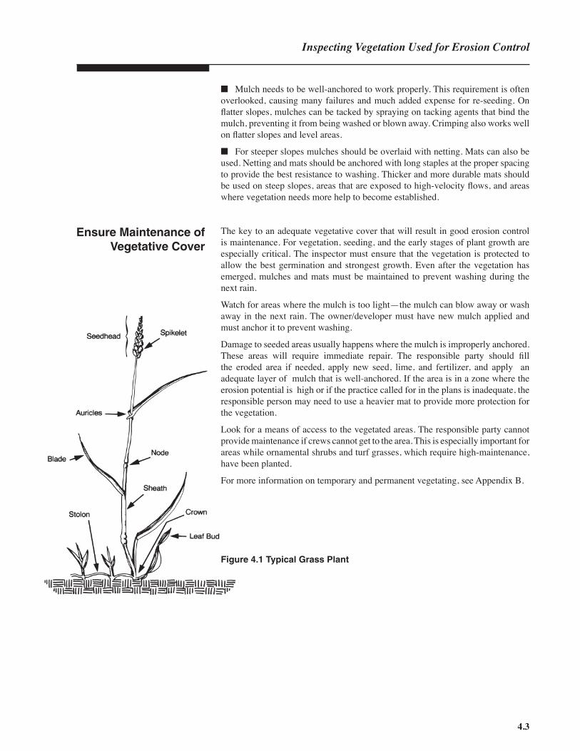
Figure 4.1 Typical Grass Plant

4
4.4

5


Inspecting IndividualPractices
The effectiveness of an erosion and sediment control system depends on the design, installation and maintenance of the individual practices. It is only when all three efforts have been done properly that the system will function to prevent accelerated erosion and off-site sedimentation.Each practice has specifi c requirements to function properly. Inspectors must be familiar with these requirements to ensure that each practice has been designed, installed and maintained properly. When you are inspecting a practice in the fi eld, fi rst check that the practice has been installed according to the design specifi cations on the approved plan. If the practice has been installed as shown on the plan, then check the appropriate section in this chapter for items that should be given special attention for each practice group.
PRACTICE INSTALLATIONDESIGN
In this chapter you will fi nd advice on what to look for when inspecting various erosion and sediment control practices. The topics are presented in the same order as they appear in the Planning and Design Manual and the Field Manual. Check the appropriate sections of those manuals for more detailed information as you encounter practices installed in the fi eld.
Inspecting Erosionand Sediment
Control Practices
5
MAINTENANCE
5.1

5
Types of ground cover can be divided into three groups—(1) hard surfaces, (2) semi-hard surfaces and (3) soft (vegetative) covers. This section provides some ideas on what to look for when you are inspecting a site using ground cover for erosion control.
Hard surfaces are those that include pavement, concrete and revetment. Some of these surfaces can be cast in place using wooden or fabric forms or they can be installed in large mats.
■ Look for proper hydrostatic pressure relief for solid slabs or liners.
■ Make sure that liners on channel slopes extend far enough up or away from the water to prevent water from cutting under, around or overtopping the liners.
■ Be certain that proper vegetation is planted in the hollows of the surface. Also, the soil fi lling the hollows should be well-prepared to provide the best growing conditions for the plants.
■ Watch for accelerated erosion and high water velocities at the toe and top of hard-surfaced slopes and at the outlets from hard surfaces.
Semi-hard surfaces consist of layers of large stone, crushed aggregate or gravel. These surfaces are often used to line channels and cover slopes.
■ Semi-hard surfaces can be washed away by high water velocities; therefore, be certain that the water velocity is within the limits for the D50 aggregate size and gradation.
■ Stone should be placed to blend with surrounding land surface to ensure that water will fl ow into the channel without erosion, not along the side of the lining.
■ Check to see if the riprap is installed according to the plan and is performing properly.
■ Ensure that adequate fl ow area has been provided.
■ Semi-hard surfaces should have geotextile fabric or a crushed stone fi lter underneath to prevent washing of the fi ne soil particles.
■ Make sure that dust control is being practiced for areas covered with stone aggregates or gravel.
5.2
Ground Covers(Surface Stabilization)
Hard Surfaces
Semi-hard Surfaces
See sections 6.10-6.16 of thePlanning and Design Manual, and
sections 6.10-6.16 of the Field Manual for more information and
common trouble points.
See section 6.84 of the Planningand Design Manual for more on
dust control.
GROUND COVERPAVEMENT GRAVEL
VEGETATION REVETMENT
CONCRETE SLABS RIPRAP

Soft ground covers (such as vegetative ground covers) are the most common and are used on moderate slopes not exposed to high water velocities. Mulches are sometimes used alone as ground cover but require frequent maintenance. Address the following questions as you inspect sites where soft ground covers are used.■ Are the plants appropriate for the site conditions?
■ Has the soil been properly amended and prepared for planting?
■ Does the area have adequate mulch and is the mulch well anchored?
■ Are the stands of vegetation adequate?
■ Have vegetative specifi cations been followed (appropriate seeding rates and mixtures)?
■ Are the established ground covers being maintained? Have provisions been made to maintain the ground covers indefi nitely?
Soft Ground Covers
See Chapter 4 and section 6.10- 6.16 of the Planning and Design Manual and the Field Manual for more information on vegetation
and soft ground covers.
Figure 5.2 Vegetative Ground Cover
5.3
Figure 5.1 Semi-hard Surface
Inspecting Erosion Control Practices

5
ENTRANCES/EXITS
PAVEMENT GRAVEL
GEOTEXTILEFABRIC
WASH RACK
Erosion can be a special problem around all entrances and exits, access roads and construction roads. Erosion in these places can cause mudholes, gullies, muddy pavement, sediment being tracked offsite, dust and complaints from neighboring landowners. Construction roads, even temporary roads, need to be stabilized to prevent erosion. Look for the following while conducting your inspection.■ Entrance and exit pads should be built with coarse gravel and stone that are suffi cient to prevent tracking of sediment onto streets or other public rights-of-way and prevent the pad from sinking into the soil.
■ Sites with heavy clay soils may require the installation of a wash rack in order to control tracking of sediment onto roads.
■ On unstable or wet soil, the stone should be spread over a layer of geotextile fabric to keep the stone from being pressed into the soil.
■ Pads may need to be extended to be effective.
■ All runoff from construction roads should be diverted to sedimentation traps retain sediment on the site.
■ Pads and roads must be maintained (adding more clean stone) to ensure proper functioning.
Entrances and Exits
See sections 6.06 and 6.80 of the Planning and Design Manual for more information on entrances/
exits and construction roads, respectively.
See the Field Manual, section6.06, for other common trouble
points.
Figure 5.3 Typical Entrance
5.4

DIVERSIONSADEQUATE SIZE PROPER GRADE
STABILIZEDCHANNELS
COMPACTEDSOIL
Diversions (dikes and channels) should be constructed as shown on the approved plans or failure of these measures is likely to occur. The most important factors in installing a diversion are its size, the grade, the elevation of the dike above the channel, compaction of the dike and stabilization of the channel. To help assure compliance, the following should be evaluated:■ A dike and its channel must be on the proper grade to ensure that the water fl ows in the desired direction. Watch for abrupt changes or reversal of grade on diversions — overfl ows and failures occur at these places.
■ Dikes must be large enough to meet the design water fl ow with 6 inches of freeboard. Be sure that they are suffi ciently wide at the top (a minimum of 2 feet) and the side slopes are 2:1 of fl atter.
■ Dikes must always be compacted or the loose soil will wash out.
■ Channels must have a large enough fl ow area to carry the expected volume of water.
■ Channels on steep grades must be lined to withstand the expected water velocity.
■ Diversions should generally parallel the site contours.
■ Diversions must be maintained routinely for proper performance, with special attention after severe storms.
Runoff Control —Diversions
See sections 6.20-6.23 of the Planning and Design Manual and
the same section in the Field Manual for more information.
Figure 5.4 Typical Diversion
Inspecting Erosion Control Practices
5.5

RUNOFFCONVEYANCE
LINERS FLOWVELOCITY
Runoff must be controlled to ensure that it will not cause accelerated erosion or off-site sedimentation. Channels, drains, and chutes must carefully follow the design specifi cations. Check these key points as you conduct your inspection.■ Vegetated channels require protection until the vegetation is fully established. Well-anchored mulch, mats or netting should be used.
■ Make sure that the fl ow cross-section is not reduced when riprap is used to line a channel. The channel excavation must be increased (or overcut) to compensate for the thickness of the riprap
■ Look to see that channels lined with riprap have a layer of geotextile fabric (fi lter cloth) under the riprap. Also, the riprap should be inlaid into the channel bank to a depth of 1.5 times the Dmax size of the riprap and set into the soil surface to prevent undercutting.
■ Inspect outlets of all runoff conveyances to ensure proper outlet protection.
■ Be sure that the slope drains have watertight joints in the pipe and that the pipe is well anchored to prevent movement.
■ Slope drains frequently fail because the water “pipes” around the inlet to the pipe. Check to see that the soil at the inlet is compacted to prevent piping.
■ Chutes have steep slopes and carry water at very high velocities. Check that the outlets are stabilized to prevent erosion and that the inlets are designed to prevent water from washing around or under the chute.
■ Determine if the chutes have subdrains, necessary to prevent hydrostatic uplift.
■ Bends in chutes are diffi cult to design and build and should be avoided if possible. Check any bends in a chute for signs of overtopping or erosion.
■ Gullies in the channel bottom mean that the velocities are too high. In this case, the channel must be redesigned by either lining the channel to withstand the fl ow velocities, changing the grade or altering the channel cross-section to lower the velocity.
■ Sloughing from the channel sides indicates stability problems. Causes of sloughing include a high water table, unstable soils, channel banks that are too steep or water velocities that are too high.
■ Overbank erosion, or fl ooding, may result from debris and sediment accumulation. The damaged areas should be rebuilt and the channel restabilized according to plan specifi cations.
■ Sediment below the channel outlet indicates that erosion is occurring either in the channel or its watershed. The problem should be located and corrected.
Runoff Conveyance —Channels, Drains
and Chutes
See sections 6.30-6.33 of the Planning and Design Manual and
the same section in the Field Manual for more information.
5
UNRESTRICTEDCROSS-SECTION
Problem Assessment
5.6

Outet protection is used to reduce high velocity fl ows from channels, culverts, pipes and other high velocity structures. Concrete stilling basins may be required for outlets that have overfalls or where a riprap apron would be too long. Check the following points of outlet protection practices.■ The installation of riprap is often problematic for outlet stabilization structures. The riprap should be inlaid into the soil to a depth of 1• times the Dmax size and have a layer of geotextile fabric under the stone.
■ The fi nished structure should be large enough to handle the full volume that the outlet was designed to carry. The cross-sectional fl ow area can be seriously reduced if no compensation is made for the thickness of the riprap.
■ The riprap should extend far enough downstream to reach a stable section of the stream. The purpose of the stabilization structure is to dissipate the energy of the water and slow water movement to keep the channel from eroding.
■ The apron of the outlet structure must be level to prevent the water from undercuttting the downstream edge of the apron.
■ Level spreaders must be constructed on undisturbed soil; no fi ll is allowed (the fi ll will settle and the lip no longer will be level). Also, the lip must be level if the spreader is to work.
■ The natural discharge area of the level spreader should handle the fl ow without eroding and not reconcentrate the fl ow (which will cause rills or gullies).
Outlet Protection
See sections 6.40-6.41 of the Planning and Design Manual and section 6.41 in the Field Manual
for more information.
Figure 5.5 Riprap OutletProtector
Inspecting Erosion Control Practices
OUTLETPROTECTION
RIPRAP APRONSHIGH
VELOCITIES
STILLINGBASINS
LEVELSPREADERS
5.7

INLETPROTECTION
GRAVELDONUTS
FABRIC
EXCAVATED BLOCK ANDGRAVEL
5
5.8
Inlet protection prevents sediment from entering the storm drains and leaving the construction site. By using inlet protectors (excavated, fabric, gravel or block and gravel), the designers can make use of the storm drains to discharge storm waters during construction. Look for problem areas within each of these practices.
■ If sediment has fi lled the excavated pool around the inlet, the contributing area for the inlet may be too large or the inlet protection structure may not have been maintained properly.
■ The capacity of the excavation around the drop-inlet protectors must be adequate for the contributing area. Also, the excavated area should be frequently cleaned and maintained.
■ These structures frequently fail because the posts are not set against the inlet and the tops of the posts are not supported or braced to on another.
■ Water should fall directly into the inlet opening, not onto the unprotected soil around the inlet box.
■ The fabric must always be buried at the bottom to prevent undercutting and to provide structural strength. The fabric should be set a minimum of 12 inches in the soil, and the trench backfi lled with compacted earth or crushed stone.
Inlet Protection
Excavated Drop-inletProtectors
Fabric Drop-inletProtectors
Figure 5.6 Excavated andFabric Drop-inlet Protectors

Inspecting Erosion Control Practices
■ Drop-inlet protectors should be set low (no more than 1.5 feet high) to allow water to fl ow over them without collapsing.
■ Also, drop-inlet protectors should be set low (less than 1.5 feet) to prevent water from overfl owing the pool behind the fabric, thus bypassing the storm inlet. In some cases a dike may be required to prevent bypassing.
■ Gravel and block and gravel inlet protectors should be set low (no more than 2 feet high) to prevent water from overfl owing the pool and bypassing the structures. The blocks must be set against the base of the inlet for support and to prevent erosion between the blocks and the inlet. A few blocks must be set on their sides to allow the pool to drain.
■ The stone used for the gravel inlet protector should be large enough that it will not wash into the inlet. The slope of the inside face of the gravel must not be too steep or the gravel will fall into the inlet. A few blocks must be set on their sides to allow the pool to drain.
■ The fi ne, “washed stone” must be on the outside face of the gravel inlet protector in order to slow the fl ow of the water through the larger stone. (The fi ne stone does not fi lter the sediment from the water. Sediment drops out of the water because the water is pooled behind the inlet protector.)
■ Gravel and block and gravel inlet protectors require fl at approaches with adequate storage to allow sediment to settle.
■ A dike may be required on the low side of the pool to prevent runoff bypassing the protector.
Gravel andBlock and Gravel
Inlet Protectors
See sections 6.50-6.53 of the Planning and Design Manual and
sections 6.50-6.52 in the Field Manual for more information.
Figure 5.7Block and Gravel Inlet Protector
5.9
SEDIMENTTRAPPING
SEDIMENTBASINS
SEDIMENTTRAPS
MAINTENANCE SILT FENCES
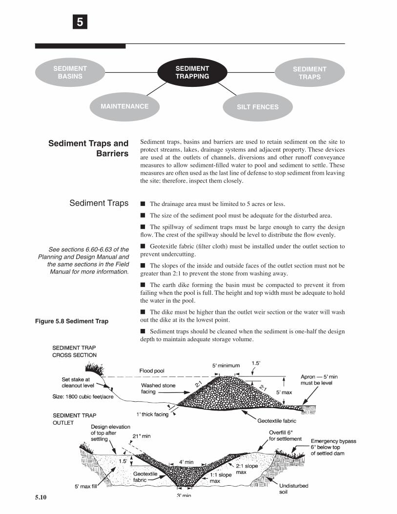
Sediment traps, basins and barriers are used to retain sediment on the site to protect streams, lakes, drainage systems and adjacent property. These devices are used at the outlets of channels, diversions and other runoff conveyance measures to allow sediment-fi lled water to pool and sediment to settle. These measures are often used as the last line of defense to stop sediment from leaving the site; therefore, inspect them closely.
■ The drainage area must be limited to 5 acres or less.
■ The size of the sediment pool must be adequate for the disturbed area.
■ The spillway of sediment traps must be large enough to carry the design fl ow. The crest of the spillway should be level to distribute the fl ow evenly.
■ Geotexitle fabric (fi lter cloth) must be installed under the outlet section to prevent undercutting.
■ The slopes of the inside and outside faces of the outlet section must not be greater than 2:1 to prevent the stone from washing away.
■ The earth dike forming the basin must be compacted to prevent it from failing when the pool is full. The height and top width must be adequate to hold the water in the pool.
■ The dike must be higher than the outlet weir section or the water will wash out the dike at its the lowest point.
■ Sediment traps should be cleaned when the sediment is one-half the design depth to maintain adequate storage volume.
Sediment Traps andBarriers
Sediment Traps
5
See sections 6.60-6.63 of the Planning and Design Manual and
the same sections in the Field Manual for more information.
Figure 5.8 Sediment Trap
5.10

■ The size of the sediment pool must be adequate for the disturbed area. Limit the drainage area to 100 acres.
■ Sediment basins require special attention because their large size makes them very hazardous if they fail. Thus, it is important that sediment basins carefully follow the dimensions, grades, elevations, pipe sizes, emergency spillway sections and other specifi cations as shown on the approved plans.
■ The conduit must be installed and function properly. The conduit joints must be watertight and must have antiseep collars or drainage diaphragms to prevent piping along the conduit.
■ Anti-fl otation weights must be used to prevent conduit movement.
■ The soil in the embankment and particularly around the conduit must be compacted to prevent piping along the conduit. Hand tamping is necessary around the conduit.
■ Trash racks can cause failures if they are improperly designed. They should catch large debris to prevent the conduit from being clogged but should not have such fi ne openings that they become clogged with leaves and cause water to overtop the embankment.
■ There should be at least 1 foot of freeboard above the emergency spillway fl ow depth to prevent overtopping the embankment.
■ The emergency spillway should be large enough to carry the 10-year storm fl ow (25-year storm fl ow in High Quality Water Zones) safely without eroding. It should be constructed in undisturbed soil and properly stabilized.
■ Large basins must be accessible to allow frequent cleaning. The sediment removed from the basins should be placed where it will not be lost off-site.
■ Sediment fences fail because they are improperly designed, installed or maintained. Silt fences must be buried at least 12 inches and backfi lled with compacted soil or stone to prevent undercutting. These fences must be adequately supported to prevent collapse from the pressure of the water and accumulated sediment.
■ Silt fences should never be placed across streams, drainage channels or areas of concen-trated fl ow. The fl owing water will collapse or undermine the fence.
■ Silt fences cannot withstand fl ows from large areas or steep slopes. The size of the con-tributing area must be limited to • acre per 100 feet of fence.
■ Sediment fences require frequent mainte-nance. The accumulated sediment should be removed often.
Sediment basins
Figure 5.9 Sediment Fence
5.11
Inspecting Erosion Control Practices
Sediment fences

STREAMCROSSINGSCULVERTS BRIDGES
FORDS
Inspect stream crossing carefully because any sediment will enter the stream directly.■ Culverts (or the overfl ow area) must be large enough to carry the storm fl ow.
■ The soil around culverts or conduit pipes must be compacted to prevent water from piping along the length of the culvert or pipe. The fi ll over the pipe should be higher than the stream banks. (This is called “island type” construction for culverts.) Inlets and outlets should be well armored.
■ Debris and construction material should be removed from the stream to prevent water cutting around culverts and bridge abutments.
■ Culverts cause additional soil disturbance when they are installed or removed. Provisions should be made to reduce sedimentation in the stream during installation and removal of the culvert.
■ Fords should be used only for shallow or intermittent streams. Use geotextile fabric covered with properly sized stone to prevent the stone from being carried downstream.
■ Bridges cause the least disturbance to the stream and should be used where practical.
■ Banks should not be fi lled to shorten the length of bridge required. Fills restrict the stream channel and can easily wash out.
■ Approaches to stream crossing should be stabilized and should have diversions to prevent runoff from entering the stream.
Stream Crossing
See sections 6.70 and 6.73 of the Planning and Design Manual and
section 6.70 in the Field Manual for more information.
Figure 5.10Typical Stream Crossing
5
5.12

BUFFER ZONES
TROUT WATERS ALONG WATERBODIES
The law requires the use of buffer zones to protect streams, lakes and other bodies of water. Check for the following points when buffer zones are required on a site.(See GS 113A-57(1) 1 for the legal requirements.)
■ Buffer zones along water bodies with no special classifi cation must be wide enough to stop all visible sediment in the fi rst one-fourth of the buffer nearest the construction work.
■ Buffer zones along designated trout waters must be a t least 25 feet wide (measured from the top of the stream bank) or wide enough so that all visible sediment is stopped in the fi rst one-fourth of the buffer nearest the construction, whichever dimension is greater.
■ Avoid the use of in-stream controls such as check dams, weirs and the like.
Buffer Zones
See the Sedimentation Control Rules. 15A NCAC 04B.0025, for the required buffer zone widths
along various waters.
Inspecting Erosion Control Practices
Figure 5.11 Buffer Zone Along Stream
5.13

MAINTENANCEINSPECTION REGULARREPAIR
FUTUREMAINTENANCE
SEDIMENTREMOVAL
Maintenance of erosion control devices is frequently overlooked on many construction sites. It is one of the most critical points in preventing accelerated erosion and off-site sedimentation.
■ The responsible party should provide for continued inspection and maintenance of erosion control practices. Maintenance for a disturbed site should be planned to continue through the life of the project.
■ All devices in the erosion and sediment control system should be inspected regularly (especially after storms). The erosion control plan should specify regular inspections and proper maintenance, such as cleaning and repairs, for each practice.
■ Sediment traps and basins should be cleaned when the settling pools are half full.
■ Contractors frequently run over diversions with heavy equipment, breaking down the dike and allowing overtopping. If the contractor must drive over the diversion, it should be stabilized with gravel and built up to the design elevation above the channel.
■ Silt fences should be repaired immediately if they are damaged.
For further information regarding proper erosion control practices, refer to the Planning and Design Manual and Field Manual. Also the Rules governing sediment control can be helpful for many practices.
Remember that the Sedimentation Pollution Control Act is performance-oriented. Even if practices are installed on a site in accordance with the approved plan, the site is only in compliance where erosion and sediment are effectively controlled.
Maintenance
5
More Information andReferences
5.14

6


Appendices
6
Human Relations The hardest part of an inspectorʼs job is dealing with people. You will be working with contractors, developers, neighbors and concerned citizens. All have rights as citizens and as human beings.
To deal effectively with people, you must be fair and consistent. You must follow the rules governing erosion and sediment control, and you must apply them fairly. Fairness means treating all people with courtesy and respect. If you show respect for the other person, that person is more likely to show respect for you. It is important to be as consistent as possible. If you apply the rules consistently to every situation, the people you deal with will know what to expect.Perhaps the most challenging part of being an inspector is carrying out your responsibilities in a professional manner. Sometimes you may feel pressured not to cite violations, but it is your job to make sure all rules are followed. The objective is to prevent accelerated erosion and off-site damage from sediment. To do this job well and be respected as a professional, you must maintain your integrity.You will visit many construction sites, offi ces and organizations. For these visits, prepare a short introduction explaining who you are, what your job is and why you are there. Give a business card to those you meet to help them remember your name and the role of your organization.
Individuals who have complaints frequently come to the inspector. Consequently, it is the inspector who has to handle heated confrontations.When a person voices a complaint, you will not have time to prepare a response. Therefore, you must resolve the situation spontaneously. You can be prepared, however, by developing skills for dealing with confl ict situations. The general guidelines in the following section will help in handling angry people.
6.1
Dealing With Angry orDiffi cult People
APPENDIX A HUMAN RELATIONS

A situation with an angry person should be handled in a manner that is satisfactory to the person, yourself and the organization you represent. Your organization relies on you to handle these situations effectively. Use these steps as a guide for developing your skills in dealing with angry people. You can tailor these skills to fi t your own personality and style.
Maintain a friendly and professional manner.You are likely to be the fi rst person an angry individual confronts. Be careful not to argue because it will only make the person become defensive and even more diffi cult.■ Show an interest in the personʼs problem and communicate your desire to solve it.■ Do not let the personʼs anger arouse your desire to retaliate. Handling a confl ict situation diplomatically is your professional responsibility and can be rewarding.■ Do not take what the individual says personally. Though the anger may be directed at you, the person is actually angry with the organization. The individual probably feels that your organization has treated him or her unfairly.
Acknowledge that a diffi cult situation exists.Show that you take the complaint seriously. It is important that you help the person maintain self-esteem. The complaint must not be viewed as unimportant. The person would not be complaining if he or she did not consider the problem important.■ Choose words and use a tone of voice that show sensitivity to the partyʼs situation. The person wants to know that you understand the situation. An angry person does not want to hear (and probably is unable to hear) that he is wrong.■ Express empathy by responding to what the person says and feels. Expressing empathy does not mean you agree with the individual. It means simply that you recognize and respond to what the person is experiencing.■ If an apology is in order, apologize for the specifi c incident and no more.
Calm the individual by questioning and verifying.By asking questions, you can verify your understanding of the situation and also demonstrate that you are willing to work with the person. This also helps the person to work with you.■ Ask questions to get specifi c information about the problem. Never assume that you understand.■ Give the person feedback to show that you understand the problem.■ Be sure that you and the person fully understand the problem.
Involve the person in solving the problem.
The next step is to get the person to cooperate in exploring alternative solutions. Show that you are interested in solving the problem. By discussing all alternatives and the consequences of each solution, you can keep the party focused on the problem and avoid side issues.
Key Steps
6
Step 1
Step 2
Step 3
Step 4
6.2

■ Ask the person to help you solve the problem. Request suggestions for solving the problem, and offer your assistance to help correct the situation. Your knowledge of erosion and sediment control can guide the party to a reasonable and legal solution.
■ Continue to ask questions in order to keep the person focused on solving the problem. If the individual is still angry, continue to empathize, showing that you understand the problem.
Handle the problem.
Having explored the possible solutions, focus on the most feasible and satisfying solution. Be positive with the person. Explain what you are going to do in a way that the person understands.
■ If he resists, go on to another alternative. Be as helpful as you can. Satisfying the personʼs desire for service and special attention can sometimes turn an opponent into an advocate.
■ Decide upon a follow-up action to ensure that the problem has been resolved satisfactorily.
There will be times when you will have to be the bearer of bad news. You may have to tell a person that you cannot solve a complaint to his or her satisfaction, or you may have to inform a responsible party of a violation. These situations can be very stressful for both you and the other person. The following section lists key steps that will help prepare you to deliver bad news.
Present the situation.
Explain the situation to the person with as few words as possible. When your discussion is concise, direct, and to the point, the person is spared the anxiety of wondering how bad the news is.
■ Prepare the person for the negative information. It may be necessary to provide a short background about the events leading up to the present situation.
■ Provide reasons why the situation has occurred. Your may be able to show that the personʼs actions were not responsible for the situation.
■ Donʼt try to give the person good news fi rst and then the bad news—this can appear patronizing.
■ Do not make the bad news seem insignifi cant; it probably isnʼt insignifi cant to the person involved.
Allow the person time to adjust.Most people need a little time to collect their thoughts and react emotionally to the bad news. Allow the person some time, but try not to leave long periods of silence. Some people perceive silence as pressure to react and therefore may react inappropriately.
Step 5
Appendix A
6.3
Step 1
Step 2
Key Steps
Being The Bearer ofBad News

■ Try discussing the positive aspects of the situation. The person may or may not hear you, but positive comments can help keep the conversation constructive and the outlook optimistic.
Accept the personʼs reactionAllow the person to express his or her feelings and opinions. It is normal to react emotionally to bad news. Allowing people to ventilate their emotions shows that you accept their feelings and helps to reduce the negative aspects of the situation.■ If the person does not offer a reaction, try talking about how you have felt or would feel in a similar situation. Then ask for the personʼs reaction. Use this technique to stress that you are empathetic to the other personʼs dilemma. However, do not get caught up in discussing your own troubles.
Demonstrate acceptance of the personʼs reaction.A person may react emotionally in many different ways and may not clearly express his or her feelings. By accepting their emotions you reaffi rm them as valuable and important. Most of us fi nd it hard to talk about emotions in the workplace, and we have trouble accurately identifying the emotions of others.You must observe and listen carefully to determine if the personʼs true feelings are being expressed■ When receiving bad news, the person may feel a wide range of emotions, such as anger, dissatisfaction, embarrassment or confusion. Respond to these emotions by remaining calm, expressing empathy, offering reassurance, or providing further explanation.■ Try to mentally identify or name the emotion that the person is feeling. Identifying the personʼs reaction allows you to accept the reaction for what it is—that is, not a personal affront to you. Understanding how the other party feels also helps you anticipate upcoming statements and remain in control of your own emotions.■ People often react by blaming another person, a group, or the system. The person is simply reacting from his anger—try not to take it personally.■ Avoid being caught in answering questions that are really meant as statements. For instance, “Donʼt you think this is unfair?” really means “I think this is unfair.” Restate the question as “I understand that you think this is unfair.”■ Sometimes you may be able to use self-disclosure to diffuse the situation. In other words, state how you have felt in similar situations. Statements such as, “I know just how you feel,” can be taken as patronizing. Rather, say, “I know how Iʼve felt in situations like this.”
Restate position points.Once the initial emotional reaction has passed, help the person put the situation into perspective.■ You can help the person see the situation more positively by expressing confi dence in his or her ability to meet the challenge and by providing genuine praise for efforts put forth.
6
Step 3
6.4
Step 4
Step 5

■ Reemphasize the basic facts about the situation and discuss any steps that can be taken to address the problem.
Offer assistance.
If appropriate, you can offer to assist the person in future actions or planning.
■ Do not offer to do something that you are not authorized to do.
■ Inform the person that it may be necessary to submit revised plans or seek legal help.
Clearly express that violations must be corrected.
An emotionally upset person may not be able to fully understand the situation or may intentionally misunderstand the conversation. Be sure that the person understands the information you have provided and knows what is expected to correct or address the situation.
■ Repeat the actions that must be taken and the required time frames.
■ Discuss the required action. if you cannot change the requirements or time frames, tell the person that you regret that you cannot change them.
■ A good way to ensure that the person understands the information you have discussed is to ask the person to repeat the details of your discussion in his or her own words. For example, “I want to be sure I havenʼt said something that might be misunderstood. Would you tell me, in your own words, your understanding of this discussion?”
Allow for future contact and follow-up.
Give the person a chance to contact you for further discussion. You may need to schedule a future meeting. You should always give the person your business card and phone numbers where you can be reached.
■ Confi rm, in writing, the conclusions reached so that all parties have a similar basis for their understanding of the situation.
These lessons were adapted from material written by the North Carolina Offi ce of State Personnel, Division of Employee and Management Development, Personnel Development Center. This center has additional information on human relations and also offers workshops in dealing with angry people and other human relations topics.
Step 6
Appendix A
Step 7
Step 8
6.5

6
APPENDIX B SOIL AND VEGETATION
Plants Recommended for Revegetating Disturbed Soilsin North Carolina Annuals Perennials
Cool-season Winter rye (grain) Tall fescue
grasses Kentucky bluegrass
Redtop
Warm-season German millet Bermudagrass
grasses Sudangrass Bahiagrass
Centipedegrass
Legumes Annual lespedeza Crownvetch
Sericea lespedeza
Marsh plants Smooth cordgrass
Saltmeadow cordgrass
Giant cordgrass
Dune plants American beachgrass
Sea oats
Bitter panicum
Saltmeadow cordgrass
6.6
Temporary Seeding recommendations for Late Winter and Early SpringSeeding mixture Species Rate (lb/acre) Rye (grain) 120
Annual lespedeza (Kobe in Piedmont and Coastal Plain, Korean in Mountains) 50
Omit annual lespedeza when duration of temporary cover is not to extend beyond June.
Seeding datesMountains — Above 2500 ft: Feb. 15 - May 15
Below 2500 ft: Feb. 1 - May 1
Piedmont — Jan. 1 - May 1Coastal Plain — Dec. 1 - Apr. 15
Soil amendmentsFollow recommendations of soil tests or apply 2,000 lb/acre ground agricultural limestoneand 750 lb/acre 10-10-10 fertilizer.
MulchApply 4,000 lb/acre straw. Anchor straw by tacking with asphalt, netting, or a mulch anchoring tool.A disk with blades set nearly straight can be used as a mulch anchoring tool.
MaintenanceRefertilize if growth is not fully adequate. Reseed, refertilize and mulch immediately following erosionor other damage.

6.7
Appendix B
Temporary Seeding Recommendations for SummerSeeding mixture Species Rate (lb/acre)
German millet 40
In the Piedmont and Mountains, a small-stemmed Sudangrass may be substituted at a rate of 50 lb/acre.
Seeding datesMountains — May 15 - Aug. 15
Piedmont — May 1 - Aug. 15
Coastal Plain — Apr. 15 - Aug. 15
Soil amendmentsFollow recommendations of soil tests or apply 2,000 lb/acre ground agricultural limestoneand 750 lb/acre 10-10-10 fertilizer.
MulchApply 4,000 lb/acre straw. Anchor straw by tacking with asphalt, netting, or a mulch anchoring tool.A disk with blades set nearly straight can be used as a mulch anchoring tool.
MaintenanceRefertilize if growth is not fully adequate. Reseed, refertilize and mulch immediately following erosionor other damage.
Temporary Seeding Recommendations for FallSeeding mixture Species Rate (lb/acre)
Rye 120
Seeding datesMountains — Aug. 15 - Dec. 15
Coastal Plain and Piedmont -- Aug. 15 - Dec. 30
Soil amendmentsFollow soil tests or apply 2,000 lb/acre ground agricultural limestoneand 1000 lb/acre 10-10-10 fertilizer.
MulchApply 4,000 lb/acre straw. Anchor straw by tacking with asphalt, netting, or a mulch anchoring tool.A disk with blades set nearly straight can be used as a mulch anchoring tool.
MaintenanceRepair and refertilize damaged areas immediately. Topdress with 50 lb/acre of nitrogen in March.If it is necessary to extend temporary cover beyond June 15, overseed with 50 lb/acre Kobe (Piedmontand Coastal Plain) or Korean (Mountains) lespedeza in late February or early March.
You can fi nd recommended permanent seeding mixtures in the North Carolina Erosion and Sediment Control Planning and Design Manual in Tables 6.11c-v on pages 6.11-31. Make copies of the seeding tables you use and insert them in this appendix.
Permanent SeedingMixtures

6.8
6
Use this blank seeding chart for your own seeding mixtures. Copy this page and write in the information about your mixtures on the copy.
Seeding Table
Seedling No. for:
Seeding mixture
Species Rate (lb/acre)
Seeding notes
Nurse plants
Seeding dates
Best Possible
Soil amendments
Mulch
Maintenance
Notes

6.9
Appendix C
WATER AND RUNOFF MANAGEMENTAPPENDIX C
The following two tables list the fl owrate of water in circular concrete and circular corrugated metal pipes for given slopes. The values listed are for pipes with no entrance or exit restrictions or controls. Pipes with either restrictions or controls will not carry the fl owrates listed here.
Concrete Pipe Full Flow Values in cubic feet per secondwhere n (roughness coeffi cient) = 0.012
Slope (ft/ft)Pipe 0.001 0.005 0.01 0.02 0.05 0.1Diameter (0.1%) (0.5%) (1.0%) (2.0%) (5.0%) (10%)
8 inches 0.4 cfs 0.9 cfs 1.3 cfs 1.8 cfs 2.9 cfs 4.1 cfs
12 1.2 2.7 3.9 5.4 8.6 12
15 2.2 5.0 7.0 10 16 22
18 3.6 8.1 11.4 16 25 36
24 7.7 17.3 24.5 35 55 77
30 14 31 44 63 99 140
36 23 51 72 102 161 228
1 cubic foot per second = 450 gallons per minute
Corrugated Metal Pipe Full Flow Values —Circular Cross-section in cubic feet per second where n(roughness coeffi cient) = 0.025
Slope (ft/ft)Pipe 0.001 0.005 0.01 0.02 0.05 0.1Diameter (0.1%) (0.5%) (1.0%) (2.0%) (5.0%) (10%)
8 inches 0.2 0.4 0.6 0.9 1.4 2.0
12 0.6 1.3 1.9 2.6 4.1 5.8
15 1.0 2.4 3.4 4.8 7.7 10.6
18 1.7 3.9 5.5 7.7 12 17
24 3.7 8.3 11.8 17 26 37
30 6.7 14.9 21 30 47 67
36 11 24 34 49 77 109

6.10
Many riprap-lined channels are not installed as the engineer designed them on the approved plans. Too often, these channels are greatly undersized in the fi eld because the contractor did not inlay the riprap. The riprap was simply dumped on the surface of the excavated channel, thus reducing the cross sectional area and restricting the fl ow in the channel.The riprap must be inlayed to prevent undercutting and loss of soil around the stone. Proper installation of riprap requires the stone to be set one and one-half times its maximum diameter (or Dmax) size into the soil. Setting the riprap into the soil means that the channel must be excavated to a larger size to accommodate the thickness of the riprap and not restrict fl ow in the channel.Remember, riprap must always be inlayed a minimum of one and one-half times its maximum diameter (Dmax) into the surrounding soil when it is installed and it must have a geotextile fabric or a stone fi lter layer under it.
In the illustration above, the approved plans call for a channel 3 feet deep, with a 4-foot-wide bottom, 2:1 side slopes, and a top width of 16 feet which requires excavating 1.1 cubic yards of soil per foot of channel. If the channel is lined with 8-inch (D50) riprap using a geotextile fabric under the stone, then the contractor must increase the excavation size to 4.5 feet deep, and a top width of 22 feet, which requires removing 2.2 cubic yards of soil per foot of channel.Looking at it from the point of fl ow restriction, say the approved plans called for a depth of 4.5 feet, a bottom width of 4 feet, 2:1 side slopes, a top width of 22 feet, and an 18-inch lining of 8 inch (D50) riprap. If the riprap is dumped on the surface of the excavated soil, then the channel has only one-half the cross-sectional fl ow area that was called for in the approved plans. This channel will not carry the fl ow rate of water that it should carry.
6
Problems withRiprap-lined Channels
Flow Restrictions vsExtra Excavation
Figure 6.1

6.11
Most of the general public is unaware of the types, severity, and extent of damage that results from erosion and sediment. This section briefl y explains how erosion and sediment from construction activities damage the construction site, streams, lakes, and public and private property.
More than a million acres of land in the United States are converted from agricultural use to urban use each year. What were once fi elds become the sites for new houses, shopping centers, schools, industrial parks, highways and airports.Construction sites are a signifi cant source of the sediment that pollutes streams and fi lls lakes. Studies show that erosion on land disturbed for construction is much higher than on land in cultivated row crops and very much higher than on land in pasture or timber.The amount of erosion that occurs is determined by the kind of soil, the slope of the terrain, the intensity of rainfall and construction methods. Much of the erosion occurs during the construction period, but areas below a construction site may erode after construction is completed because of increased runoff from compacted soil, impervious pavement and parking lots.Damage to the land does not come from erosion alone. Increased runoff from an eroding site erodes stream banks and channels, and causes fl ooding downstream. Sediment from the erosion pollutes streams, fi lls lakes, and damages the area where it is deposited.
Erosion damage to the construction site includes rilled and gullied slopes, gullies in waterways and channels, washed-out roads and streets, undercut pavements and pipelines, clogged storm sewers, fl ooded basements and debris-laden work areas. Damage of this kind must be repaired. It increases the cost of construction and causes delays in work schedules.Also, fertile topsoil is lost through erosion. This loss means that lawns and gardens will be diffi cult to establish and landscaping costs will be higher.
Streams in a stable environment have banks covered with vegetation, and clean, stable bottoms. They rarely fl ood. In contrast, stream channels below a construction site can fl ood or become fi lled with sediment due to increased runoff and erosion from the construction site. Larger fl owrates of runoff erode streambanks, cause sloughing of large parts of the streambank, and can force the stream to meander.Streams that are stressed by increased runoff cut larger channels by widening or deepening the channel, depending on the erodibilities of the soil layers. Active erosion or sloughing of the streambanks is visible. The bottoms are covered with sediment, either from the eroding construction site or the streambanks. The aesthetic value of the stream is seriously reduced.Land owners along such streams may fi nd their property washing away or damaged by thick deposits of sediment.
Damages from Erosionand Sediment
Erosion on ConstructionSites
Damage to theConstruction Site
Damage to StreamChannels
EROSION AND SEDIMENTATIONAPPENDIX D
Appendix D

6.12
Sediment is the greatest single pollutant of streams, lakes, ponds and reservoirs. It lowers the quality of water for municipal and industrial uses and for boating, fi shing, swimming and other water-based recreation. Suspended sediment increases the costs of water treatment and causes increased wear on equipment such as turbines, pumps and sprinkler irrigation systems.Sediment can destroy the habitat for fi sh and other aquatic animals and plants. If the sediment loads are heavy, fi sh and shellfi sh can suffocate due to sediment clogging their gills.Many pollutants such as pesticides, phosphates, and other chemicals are adsorbed on the sediment particles and carried with the sediment.
Sediment damages the areas where it is deposited. It can bury lawns, fi ll ditches, and clog storm sewers, culverts and drains. Thick deposits can make an area unsuitable for use as a park or playground. Sediment reduces the storage capacity or reservoirs and may fi ll small ponds and lakes. If sediment reaches major waterways, it can block navigation channels, or fi ll harbors and estuaries with silt.
Estimating erosion or measuring sediment volumes can be diffi cult tasks. This section outlines two methods that have been used to estimate soil losses and fi nd sediment volumes—there is no widely accepted or standard method. Accuracy of the methods is variable.
Soil loss from a fi eld can be measured with surveying equipment. To fi nd how muck soil has been lost, the fi eld is surveyed and contours of elevation established. The present contours of the fi eld are then compared with the original contours. The volume of soil is calculated from the differences in elevation of the soil surface and the areas over which the soil loss occurred.The following points can help when using this method.■ Sometimes it is diffi cult to obtain contoured site plans of a project. You can check with the U.S. Geological Survey, Soil Conservation Service, the Agricultural Conservation and Stabilization Service, the Forest Service or other such organizations for topographic maps or site plans with elevation contours.
■ Roughness of the fi eld soil surface greatly infl uences the measured volume of soil loss. Be sure to measure the soil surface in a consistent manner so that the soil loss volume is accurate.
■ All soil lost from a fi eld may not fl ow off-site. Mush soil can be redeposited in the same fi eld, changing the shape of the fi eld slope, but not violating the law by losing sediment off-site.
■ If sediment is not being lost off-site, the site may still not be in compliance with the provisions of the law requiring slopes to be stable and all surfaces covered.
Measured sediment volume is usually used in legal proceedings to prove damages and non-compliance with the law.
Surveying instruments can be used to fi nd the total volume of sediment. A grid pattern of transects, or straight lines, is established across each sediment deposit
6
Estimating andMeasuring Erosion and
Sediment Volumes
Damage to Water
Measuring SedimentVolumes
Measuring Soil Lossesfrom a Field
Damage to Public andPrivate Property

6.13
and the sediment depth is measured at the points of the grid. The average depth of sediment is multiplied by the area of the grid section to arrive at a sediment volume lost.
The following points can help you in measuring sediment volume.
■ Sediment can be carried long distances; therefore, you may have to make measurements far from the originating site to get an accurate measurement.
■ The total volume of sediment actually lost may be much larger than the amount you can measure. The sediment can be deposited in layers too thin to measure or swept too far away to be found.
For further assistance, consult state regulatory agencies, the Soil Conservation Service, the Cooperative Extension Service, and state university departments of soil science, civil and agricultural engineering.
This section will help you in properly equipping your offi ce and your vehicle to do a thorough inspection. The items listed are suggested only; please add to the list as necessary.
■ Hand level—to measure slopes and elevations.
■ Measuring wheel.
■ Measuring tape, 100 feet.
■ One-man surveyorʼs rod and rod holders.
■ Surveying level or transit.
■ Surveying fl ags or stakes.
■ Camera.
■ Calculator.
■ Inspection reports.
■ Aerial photographs of your region of responsibility.
■ Topographic maps of your region of responsibility.
■ Engineering scales for appropriate scales of maps and photos.
■ Planimeters and other drafting tools to properly measure sites from plans, topographic maps, and aerial photos.
■ Soils surveys or soils maps of your region of responsibility.
■ Calculator.
■ Video Camera.
Appendix D
TOOLS OF THE INSPECTORAPPENDIX E
Appendix E
For Your Vehicle
For Your Office

6.14
CONVERSIONS, TABLES, REFERENCE INFORMATIONAPPENDIX F
6
Slope Measurements and Conversions
RatioRun : Rise Percentage (%) Degrees (˚) Sine of Slope
1:1 100% 45˚ 0.707
1.25:1 80 38.7 0.625
1.50:1 66.7 33.7 0.555
1.75:1 57 29.7 0.495
2:1 50 26.6 0.448
2.25:1 44.4 24.0 0.407
2.50:1 40 21.8 0.371
2.75:1 36.4 20.0 0.342
3:1 33.3 18.4 0.316
3.50:1 28.6 15.9 0.274
4:1 25 14.0 0.242
5:1 20 11.3 0.196
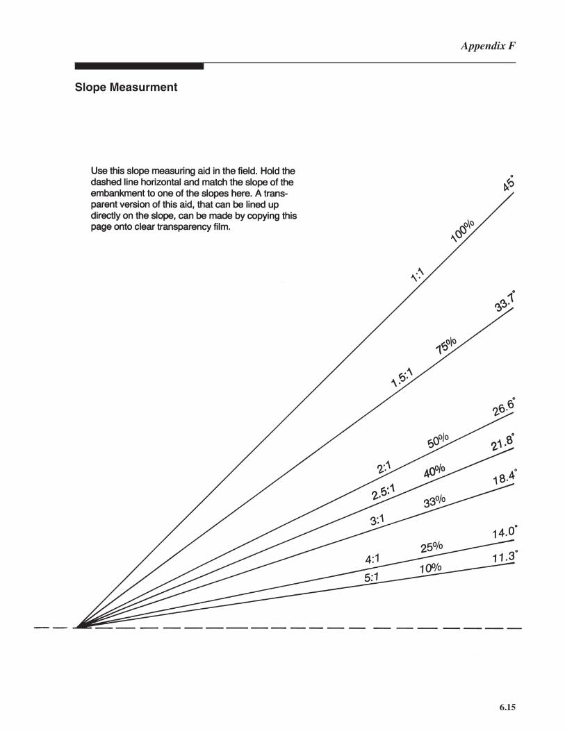
6.15
Slope Measurment
Appendix F

6.16
Soil TexturalClassifi cation
6

6.17
The following pages contain certain information about crushed stone, standard sizes and its use in erosion control. The fi rst table lists National Stone Association (NSA) sizes and the following tables list standard North Carolina Department of Transportation sizes.
Crushed StoneReferences
Appendix F
Quarried Stone for Erosion and Sediment Control
GRADED RIPRAP STONE
Size Inches (sq. openings) Wave Height3 Velocity4 Filter Stone
NSA No. Max. Avg.1 Min.2 (ft.) (ft./sec.) NSA Size No.
R-1 1.5 3/4 (No.8) — 2.5 FS-1
R-2 3 1.5 1 0.3 4.5 FS-1
R-3 6 3 2 0.5 6.5 FS-2
R-4 12 6 3 1.0 9.0 FS-2
R-5 18 9 5 1.5 11.5 FS-2
R-6 24 12 7 2.0 13.0 FS-3
R-7 30 15 12 2.5 14.5 FS-3
R-8 48 24 15 4.0 — FS-3
ARMOR STONE*
Wt. in Short Tons
NSA No. Max. Avg. Min.2 Wave Height (ft.)5 Filter Stone
A-1 4.0 3.0 2.0 8.0 (See Supplemental
A-2 6.0 4.5 3.0 10.0 Engineering Notes)
A-3 8.0 6.5 5.0 12.0
*Due to the large size of armor stone, one or more underlayers may be required in addition to stone fi lter.
FILTER STONE
Size Inches (sq. openings)
NSA No. Maximum Average Min.(2)
FS-1 3/8 No. 30 No. 100
FS-2 2 No. 4 No. 100
FS-3 6.5 2.5 No. 16
The above tables assume a stone dry density of 165 pounds per cu.ft.1“Average” is that size exceeded by at least 50 percent of the total weight of the tonnage shipped; i.e., 50 percent of the tonnage shall consist of pieces larger than the “average” size (normally half the specifi ed nominal top size).2Pieces smaller than the minimum size shown shall not exceed 15 percent of the tonnage shipped.3Wave height is the vertical distance from wave crest to wave trough. The wave height given in the table is the average height of the one-third highest waves in the incident wave train.4The stream velocity is the velocity at mid-stream or at a point 10 feet from the bank, whichever is closest to the bank.5The stone industry generally is unable to economically produce armor stone in sizes to fi t the 6-ft. wave height category. Therefore, the reader should use NSA No. A-1.

6.18
6
The National Stone Association (NSA) has devised the above Tables to defi ne a number of standard sizes from which the reader may select the one most appropriate to the anticipated service situation. Designations R-1 through R-8 describe “graded” riprap or revetment stone—grading designed to produce a well bonded mass heavy enough to resist the forces of waves or stream fl ows of the magnitude shown.The larger armor stones designated A-1 through A-3 are more closely sized, usually “hand-picked” at the quarry and individually placed, piece by piece, by well-equipped heavy construction contractors.The proper size of fi lter stone for the underlayer or “fi lter pack” for revetment stone depends upon the type of underlying soil as well as the size of protective riprap or armor stone above. In brief, the fi lter layer must be fi ne enough to prevent the underlying soil material from being washed up through it and yet coarse enough to prevent its own fi ner particles from being washed out through the voids in the protective cover layer above. In case the underlying soil is very fi ne and the riprap or armor stone quite large, it may be necessary to place two layers of fi lter stone—a fi ner layer at the bottom (FS-1 or FS-2, say) and a coarser bedding layer immediately below the riprap (perhaps FS-3). A more complete guide to stone sizes for fi lter layers may be found in the Army Corps of Engineers ̓“Shore Protection Manual,” Volume II, paragraph 7.377h, Reference No. 15, page 32, as well as in various soil mechanics texts and other sources.Adapted from, Quarried Stone for Erosion and Sediment Control. National Stone Association, 1-91 SEC 5, Washington D.C., 1991.
SupplementalEngineering Notes

6.19
Appendix F
Riprap and Erosion Control Stone SizesNorth Carolina Department of Transportation Specifi cationsStone density is assumed to be 165 pounds per cubic foot. Stone shape is assumed to be spherical. Percentages indicate amount passing givenscreen sizeApprox. Riprap RiprapWeight of Class Class Approx. Class Class Slopespheres 1 2 Size A B Protection(pounds) (inches) Stone
290 18
250 100% 17
200 100% 16
170 15
140 14
110 13
86 0 - 40% 12
66 11 Equally
50 0-70% 0 - 5% 10 distributed
36 9
26 0% 8 90-100%
21 7.5
17 7
15 0 - 10% 6.5
11 6
6.2 5
5 0% 4.5
3.2 4 Equally 30 - 70%
1.5 3 distributed
0.8 2.5 10-35%
0.4 2
0.05 1
0.02 0.75 0 - 5%
Or use Class A Riprap
Notes:
1) Slope Protection stone is to be used for control of splash erosion and surface erosion only, it is not to be used to line channels or where water fl ows are concentrated.
2) Class 1 and Class 2 riprap are specifi ed by weight of the individual pieces of stone.
3) Class A and Class B riprap are specifi ed by sizes of the individual pieces of stone.
4) Class 1 and Class B riprap are equivalent for practical purposes.
Adapted from the North Carolina Aggregates Association

6.20
6
Crushed Stone Sizes and UsesNorth Carolina Dept. of Transportation Sizes
Coarse Aggregate Size in inches, or
Standard Size # Sieve Size (square openings)
Maximum Average* Minimum Best Uses
4 2 1 3/4 Bituminous Plant Mix Pavement
467M 2 3/4 #4 Bituminous Plant Mix Pavement
5 11/2 3/4 1/2 Bituminous Surface Treatment Mat Coat
57 11/2 1/2 #4 Structural Concrete Shoulder Drain, Subsurface Drains
57M 11/2 3/4 - 1/2 #4 Portland Cement Concrete Pavement, Subsurface Drains
6 1 1/2 3/8 Bituminous Surface Treatment
67 1 3/8 #4 Structural Concrete, Bituminous Plant Mix Pavement
78M 3/4 #4 #8 Bituminous Plant Mix Pavement, Bituminous Surface Treatment, Weep Hole Drains, Structural Concrete
14 3/8 #4 $8 Bituminous Structural Treatment
All standard sizes of stone listed above are free of fi nes (washed stone);therefore they will resist clogging.
Stone sizes SA, ABC and ABC(M) contain signifi cant amounts of fi nes.These standard sizes should not be used for subsurface drains or facingstone for rock dams or outlets for sediment traps.
SA 2 #4 #50 Stabilizer Aggregate, Pothole Filler, Soil Stabilizer, Sub-base Course ABC 11/2 3/8 350 Aggregate Base Course, Bituminous Plant Mix Pavement
ABC(M) 11/2 1/2 #40 Maintenance Stabilization, Pothole Filler, Soil Stabilizer
Fine Aggregate
1S 3/8 #16 #50 Blotting Sand, Bituminous Pavement Retreatment 2S 3/8 #30 #50 Structural Concrete, Subsurface Drainage, Blotting Sand 2MS 3/8 #30 #100 Structural Concrete 4S #4 #40 #80 Mortar Sand
*Average size represents the approximate 50% size for the standard size gradation.NOTE: See the North Carolina Department of Transportation Standard Specifi cations for Roads and Struc-tures, Section 1005 for technical specifi cations for coarse and fi ne aggregate gradations.

6.21
Sizes #4 and #467MSizes #4 and #467M can be used to control splash or sheet erosion. Do not use these sizes to line channels or where concentrated fl ows occur.This stone provides excellent stabilization for construction roads and construction entrances and exits in dry soils. If the soils are too wet, larger sizes may be needed.These sizes make excellent sub-base courses for parking lots and permanent roads, providing better drainage and greater support for the fi nal pavement.These sizes are between NSA R-1 and R-2.
Sizes #5, #57 and #57MRoughly equivalent to NSA size R-1, these sizes are excellent for use in subsurface drains and as facing stone for rock dams, sediment trap outlets, and block and gravel inlet protectors. There are no fi nes in these sizes; thus, they will resist plugging.
Sizes SA, ABC and ABC(M)These sizes are best used as the base course for permanent paving and to stabilize wet soils. They closely approximate NSA FS-2.
Parking AreasFor sites that plan large permanent parking areas, much erosion can be prevented by installing a base course of crushed stone just after the site is graded. This prevents construction equipment from creating large areas of ruts and puddles. Acceptable stone to use is ABC, ABC(M), SA, #467M, or #4, depending on the soil and site conditions.
Class A RiprapClass A riprap is the same as NSA R-3.
Class B and Class 1 RiprapThese sizes are approximately the same as NSA R-5.
Class 2 RiprapThis stone closely approximates NSA R-6.
Slope Protection StoneSlope protection stone is between NSA R-3 and R-4.
Sizes 2S and 2MSFine aggregates #2S and #2MS are equal to NSA FS-1. Size #2S can be used in subsurface drains.
Notes About CrushedStone Used for Erosion
Control
Appendix F

6.22
On the following pages, you will fi nd two views of a highway construction project. The lower portion of the pages are the construction plans, and the upper portion of the pages are aerial photos of the same project. These plans and photos are included here to allow you to gain experience in reading construction plans and aerial photos.The construction plan shows the “clearing and grubbing” phase for a new highway. The aerial photos show the site at an interim stage of construction. This project was chosen because the construction plans and aerial photos are relatively clear and uncluttered. Except for its simplicity, this project is typical of many other projects you will encounter as an inspector.When you are studying these plans and photos, please note that the light gray contour lines show the original topography of the site. The roadway has been well-fi tted to the original topography, requiring minimal fi lls and excavations; however, the constructed roadway has changed the fl ow patterns signifi cantly from those originally at the site. Also the contours and the plans were taken from two sources; thus there are a number of places where the fl ow paths of the streams do not fi t the contours exactly. Problems such as these are common when the topographic and the construction plans are done at different times or by different groups.Study the plans to fi nd the erosion and sediment control measures. The following points can help your review.■ Check the contours of the site to determine the higher and lower areas, and the direction of fl ow of the runoff. The contours shown are for the undisturbed site, before construction. The graded site will have only gradual slopes.■ Note the perimeter protection, especially near the streams crossing the project. Is it adequate?■ Pay attention to critical areas, such as steep cut and fi ll slopes, stream crossings, channels, outlets of pipes and diversions and construction access routes.■ Are the devices and measures properly placed?■ Look for adequate access and space for constructing and maintaining the erosion and sediment control measures.■ The aerial photo can help you determine if the measures are adequate and/or working. What would you look for to fi nd out if an area is not adequately protected?■ The captions point out certain measures on the plans and on the aerial photo. Can you fi nd other measures not pointed out by the captions?■ Have all the measures listed on the plans been is stalled (check the photo)?■ What additional or alternative measures would you recommend?
6
APPENDIX G CONSTRUCTION PLANS AND AERIAL PHOTOS

7