Types of Usability Testing or Usability Inspection Chapter 10.3.

Manual of Bridge Inspection 2014
Page 61
Chapter4:InspectionTypesThe scope, intensity, and frequency of bridge safety inspections are discussed here to provide a better
understanding of the purpose and use of each inspection type and to assist in the development of scope
of inspection work for individual inspections. An inspection event, particularly for large, complex, or
deficient structures, often requires that a variety of inspection types be performed, using a variety of
methodologies. For example, a fracture critical bridge may also require an underwater inspection and a
routine inspection.
Frequency
All bridges greater than or equal to 10‐feet clear span shall receive an annual inspection with no
inspection outside of 18‐months. Structures that are Fracture Critical shall receive a hands‐on arms‐
length inspection of the Fracture Critical Members not to exceed (NTE) 24 months. Structures with
substructure units in water unfit for regular probing or visual inspection (often deeper than 5‐feet at the
substructure unit) shall receive Underwater Inspections not to exceed 60‐months. In‐Depth inspections
are typically scheduled for Major Bridges and Complex Bridges on a five year cycle. Damage Inspections
are unscheduled inspections to assess structural damage resulting from environmental factors or human
actions (i.e. barge‐clip, overheight hit, earthquake).
Criteria for increasing the frequency or level of inspection beyond the minimum statutory or policy
requirements shall be at the discretion of the Control Authority or Program Manager. Often the
discretion is based on a rapid or unforeseen change from the results of a previous inspection. Rationale
for scheduling increased frequencies for an In‐Depth, Special or increased frequency Routine, Fracture
Critical or Underwater Inspection should consider: age, traffic volume, size, susceptibility to collision,
extent of deterioration, performance history of the bridge type, load rating, location, recent failures of
similar structure or material type, structural damage, scour and erosion, drift, streambed movement, ice
loading or navigation traffic collision national defense designation, detour length and social and
economic impacts due to the bridge being out of service.
Manual of Bridge Inspection 2014
Page 62
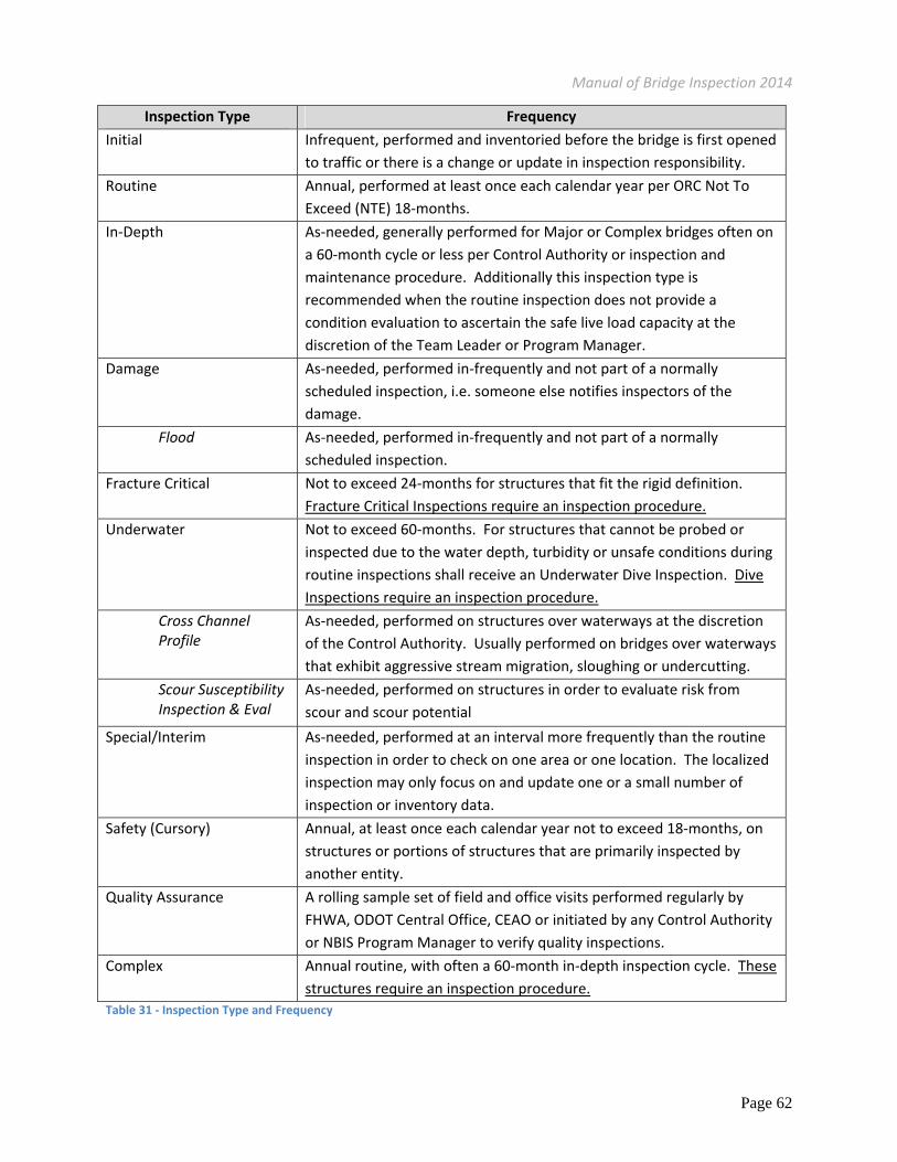
Inspection Type Frequency
Initial Infrequent, performed and inventoried before the bridge is first opened
to traffic or there is a change or update in inspection responsibility.
Routine Annual, performed at least once each calendar year per ORC Not To
Exceed (NTE) 18‐months.
In‐Depth As‐needed, generally performed for Major or Complex bridges often on
a 60‐month cycle or less per Control Authority or inspection and
maintenance procedure. Additionally this inspection type is
recommended when the routine inspection does not provide a
condition evaluation to ascertain the safe live load capacity at the
discretion of the Team Leader or Program Manager.
Damage As‐needed, performed in‐frequently and not part of a normally
scheduled inspection, i.e. someone else notifies inspectors of the
damage.
Flood As‐needed, performed in‐frequently and not part of a normally
scheduled inspection.
Fracture Critical Not to exceed 24‐months for structures that fit the rigid definition.
Fracture Critical Inspections require an inspection procedure.
Underwater Not to exceed 60‐months. For structures that cannot be probed or
inspected due to the water depth, turbidity or unsafe conditions during
routine inspections shall receive an Underwater Dive Inspection. Dive
Inspections require an inspection procedure.
Cross Channel Profile
As‐needed, performed on structures over waterways at the discretion
of the Control Authority. Usually performed on bridges over waterways
that exhibit aggressive stream migration, sloughing or undercutting.
Scour Susceptibility Inspection & Eval
As‐needed, performed on structures in order to evaluate risk from
scour and scour potential
Special/Interim As‐needed, performed at an interval more frequently than the routine
inspection in order to check on one area or one location. The localized
inspection may only focus on and update one or a small number of
inspection or inventory data.
Safety (Cursory) Annual, at least once each calendar year not to exceed 18‐months, on
structures or portions of structures that are primarily inspected by
another entity.
Quality Assurance A rolling sample set of field and office visits performed regularly by
FHWA, ODOT Central Office, CEAO or initiated by any Control Authority
or NBIS Program Manager to verify quality inspections.
Complex Annual routine, with often a 60‐month in‐depth inspection cycle. These
structures require an inspection procedure.
Table 31 ‐ Inspection Type and Frequency

Manual of Bridge Inspection 2014
Page 63
Initial Inspections
An Initial Inspection is the first inspection of a new structure, a structure that has changed ownership or
a reconstructed structure. It is a close‐up hands on inspection of the structure to document its baseline
condition.
Purpose of Initial Inspections
The purpose of the Initial Inspection is to verify the safety of the bridge, in accordance with the NBIS and
Department standards, before it is put into service. It also serves to provide required inventory
information of the as‐built structure type, size, and to document its structural and functional conditions
by:
Providing all Structure Inventory & Appraisal (SI&A) data required by Federal regulations along
with all other data required by Department standards.
Determining baseline structural conditions and eliminate deficiencies recorded under previous
structural assessments.
Clearance envelopes (for features carried and those intersected) and bridge waterway openings
are to be documented at this time.
Identifying maintenance needs, including preventative maintenance activities.
Noting the existence of elements or members requiring special attention, such as fracture
critical members, fatigue‐prone details, and underwater members.
Verify construction/rehabilitation contracts.
Documents, including but not limited to, photographs, drawings (design, as‐built and shop
drawings), scour analysis, foundation information, hydrologic and hydraulic data are to be
inserted into the bridge file. Selected construction records (e.g. pile driving records, field
changes, etc.) may also be of great use in the future and should be included.
Unexpected problems with a small number of newly constructed bridges have demonstrated
that safety inspections may be needed even for new bridges to ascertain their initial and long‐
term safety.
Uncompleted non‐bridge maintenance items (e.g. roadway drainage, channel debris, etc.) have
caused significant bridge damage in several incidences. The inspection cycle is needed for
effective planning and programming of bridge maintenance activities, especially on‐demand
repairs and preventative maintenance items. In addition, new asset management analysis tools

Manual of Bridge Inspection 2014
Page 64
for bridges and other assets require high quality bridge condition and needs data collected at
regular intervals to provide good decision‐making tools for bridge owners.
In the event that responsibility of a bridge changes, a letter notifying the Central Office, Office of
Structural Engineering, shall be written by the Control Authority retiring the structure. The letter shall
inform all parties of their inspection and maintenance responsibilities. The SFN will remain the same
however the program responsibilities will change.
Scope and Frequency of Initial Inspections
The level of effort required to perform an Initial Inspection will vary according to the structure’s type,
size, design complexity, and location. An Initial Inspection is to be a close‐up, hands‐on inspection of all
members of the structure to document the baseline conditions. Traffic control and special access
equipment may be required.
Initial Inspections are performed for each structure after construction is essentially complete and before
the bridge is put into service (or returned to service for bridges that have had a major reconstruction).
Bridges open to traffic during construction operations are required to be inspected. Anytime ownership
changes, a bridge is newly constructed or receiving a major rehab, the bridge shall receive an initial
inspection.
Routine Inspections
Routine Inspections provide documentation of the existing physical and functional conditions of the
structure. All changes to the inventory that have occurred since the previous inspection are also to be
documented and updated. The written report will include appropriate photographs and
recommendations for major improvements, maintenance needs (preservation, preventative
maintenance or on‐demand repairs), and follow‐up inspections. Load capacity analyses are re‐evaluated
only if changes in structural conditions or pertinent site conditions have occurred since the previous
analyses.
Purpose of Routine Inspections
A Routine Inspection shall satisfy the requirements of the NBIS and Department standards. Routine
Inspections serve to document sufficient field observations/measurements and load ratings needed to:
Determine the physical and functional condition of the structure.

Manual of Bridge Inspection 2014
Page 65
Determine the need for establishing or revising a weight restriction on the bridge.
Determine improvement and maintenance needs.
Ensure that the structure continues to satisfy present service and safety requirements.
Identifying and listing concerns of future conditions.
Identify any inventory changes from the previous inspection.
Scope and Frequency of Routine Inspections
Routine Inspections are regularly scheduled inspections performed once each calendar year. No routine
inspection shall occur outside of an 18 month interval since the previous inspection. The interval for
Routine Inspections should be reduced from the maximum calendar year inspection when the engineer
determines that the bridge conditions have deteriorated to the point where additional scrutiny is
warranted to ensure public safety. This reduced frequency inspection would be called a special interim
inspection.
The level of scrutiny and effort required to perform a Routine Inspection will vary according to the
structure’s type, size, design complexity, existing conditions, and location. Generally, every element in a
bridge does not require a hands‐on inspection during each Routine Inspection to provide an acceptable
level of assurance of the bridge’s ongoing safety. The difficulty is that the areas not needing close‐up
scrutiny cannot always be determined until after the entire bridge has been inspected and non‐critical
areas identified. To provide a reasonable level of confidence in the safety of the bridge, knowledge of
the structure and good engineering judgment are necessary when considering those portions that will
not receive the close‐up scrutiny with each inspection. Areas that may be more difficult to access but
warrant a hands‐on inspection in each Routine (or Special) Inspection, include, but are not limited to:
Those areas explicitly determined by previous inspections
Load carrying members in Poor condition, critical sections of controlling members on posted
bridges
Scour critical substructure units
Areas determined by the Program Manager, for example:
o End regions of steel girders or beams under deck joints
o Cantilever portions of concrete piers or bents
o Ends of Prestressed concrete beams at continuity diaphragms
o Pin and Hanger / Hinge assemblies
o Redundancy retrofit systems

Manual of Bridge Inspection 2014
Page 66
o Vertical Clearance restrictions on state routes
o New product testing for maintenance application
o Reoccurring maintenance needs that pose structural or safety concerns
During Routine Inspections, particular attention should be given to scour, erosion, (new rock fields,
debris) and overall stability of the substructure.
Routine Inspections are generally conducted from the deck, ground and/or water levels, ladders and
from permanent work platforms or walkways, if present. Inspection of underwater members of the
substructure is generally limited to observations during periods of low flow and/or probing/sounding for
evidence of local scour.
The application of these inspection guidelines do not relieve the Control Authority or Program Manager
in charge of the inspection from the responsibility to perform other In‐Depth Inspection tasks and/or
tests needed to ascertain the condition of the bridge and assure the safety of the traveling public.
Increased intervals or level of inspection are at the discretion of the Control Authority or Program
Manager.
In‐Depth Inspections
An In‐Depth Inspection is a close‐up, hands‐on inspection of one or more members and a close visual of
all members above or below the water level to identify any deficiency not readily detectable using
Routine Inspection procedures. An In‐Depth Inspection may be limited to certain elements, span
group(s), or structural units of a structure, and need not involve the entire structure. Conversely, In‐
Depth Inspections may include all elements of a structure. In‐Depth Inspections can be conducted by
itself or as part of a Routine or other type of inspection.
Purpose of In‐Depth Inspections
In‐Depth Inspections serve to collect and document data to a sufficient detail needed to quantify the
physical condition of a bridge. This data is more detailed than data collected during a Routine
Inspection.
In‐Depth Inspections should be routinely scheduled for selected bridges based on their size, complexity
and/or condition. Major or complex bridges represent large capital investments and warrant closer
scrutiny to ensure that maintenance work is identified and completed in a timely manner. These bridges
tend to be more critical to local and area transportation because of the usual lack of suitable detours. It

Manual of Bridge Inspection 2014
Page 67
may be more difficult to provide a complete snapshot of the bridge conditions when access difficulties
limit the scope of Routine Inspections.
Scope and Frequency of In‐Depth Inspections
The level of effort required to perform an In‐Depth Inspection will vary according to the structure’s type,
size, design complexity, existing conditions, and location. Traffic control and special equipment, such as
under‐bridge cranes, rigging, or staging may be needed for In‐Depth Inspections. Personnel with special
skills such as divers and riggers may be required. Non‐destructive field tests and/or material tests may
be performed to fully ascertain the existence of or the extent of any deficiency. On small bridges, the In‐
Depth Inspection, if warranted, should include all critical elements of the structure.
For large or complex structures, these inspections may be data driven or scheduled separately for
defined segments of the bridge or for designated groups of elements, connections or details that can be
efficiently addressed by the same or similar inspection techniques. If the latter option is chosen, each
defined bridge segment and/or each designated group of elements, connections or details should be
clearly identified as a matter of record and should be assigned a frequency for re‐inspection. The
activities, procedures, and findings of In‐Depth Inspections shall be completely and carefully
documented more than those of Routine Inspections. Stated differently, In‐Depth Inspection reports will
generally be detailed documents unique to each structure that exceed the documentation of routine
inspection forms.
Figure 32 ‐ In‐depth Inspection of Suspension Cable

Manual of Bridge Inspection 2014
Page 68
A structural analysis for load carrying capacity may be required with an In‐Depth inspection to fully
evaluate the effect of the more detailed scrutiny of the structure condition.
An In‐Depth Inspection can be scheduled in addition to a Routine Inspection, though generally at a
longer interval, or it may be a follow‐up to a previous inspection. An In‐Depth Inspection that includes all
elements of the structure will satisfy the requirements of the NBIS and take the place of the Routine
Inspection for that cycle.
In‐Depth Inspections do not reduce the level of scrutiny for Routine Inspections. Program Managers
shall schedule In‐Depth Inspection based upon condition and importance. Increased intervals are up to
the discretion of the Control Authority or Program Manager.
Damage Inspections
Damage Inspections are performed following
extreme weather‐related events, earthquakes
vandalism and vehicular/marine traffic crashes.
When major damage has occurred, the Inspectors
will need to evaluate fractured or failed
members, determine the amount of section loss,
take detailed measurements for misalignment of
members, check for any loss of foundation
support, etc.
Purpose of Damage Inspections
Damage Inspections serve to determine the nature, severity, and extent of structural damage following
extreme weather‐related events and vehicular and marine traffic collisions/accidents for use in
designing needed repairs. Damage Inspection findings shall be used to determine the immediate need to
place an emergency restriction on a bridge (e.g. weight restriction or closure) for vehicular traffic. If a
bridge is closed to vehicular traffic, the need to close it to pedestrian traffic shall also be determined.
The findings of a Damage Inspection may be used to re‐coup the costs of inspection and needed repairs
or reconstruction from involved parties or other governmental agencies. Accordingly, documentation of
the inspection may be critical in these efforts. For Department bridges, the extent of damage and
estimated costs of repair should be reported to the District damage coordinator. Photographs, videos
Figure 33 ‐ Damage inspection

Manual of Bridge Inspection 2014
Page 69
and sketches can be extremely helpful. See Appendix. Over‐Height Steel Beam Bridge Strike Form for
additional information regarding reporting ODOT District bridge emergencies in accordance with
SAC4SR7 emergency funds.
Scope and Frequency of Damage Inspections
A Damage Inspection is an unscheduled inspection to assess the structural damage resulting from
environmental factors or human actions. Damage Inspections are performed on an as‐needed basis.
The amount of effort expended on this type of inspection will vary significantly depending upon the
extent of the damage, the volume of traffic encountered, the location of the damage on the structure,
and documentation needs. The scope of a Damage Inspection must be sufficient to determine the need
for emergency load restrictions or closure of the bridge to traffic, and to estimate the level of effort
necessary to accomplish repairs. The capability to make an on‐site determination of the need to
establish emergency load restrictions may be necessary.
Flood Inspections
To combat the loss of structures from the transportation system
and protect our valued infrastructure, Program Managers
should assess and prioritize bridge‘s vulnerability to scour so
that critical bridges can be identified for closer monitoring and
possible implementation of scour countermeasures.
See Appendi. Scour Critical Plan of Action (POA) and Appendix.
Scour Critical Assessment Checklist for support to help
determine the Scour Susceptibility.
The Program Manager is to establish an internal procedure to monitor bridges that are vulnerable to
scour during or immediately after periods of high water. The following elements are recommended for
consideration as part of the procedures:
A list and map of bridges that are to be monitored during periods of high water. Bridges
vulnerable to scour include scour critical bridges, those that may have scoured previously or that
may have a history or be susceptible to degradation and aggradation.
Because high stream flows can be localized and information about its severity and extent may
not be immediately available, a method of reporting the occurrence and extent of high water is
Figure 34 ‐ Flood Inspection Signage

Manual of Bridge Inspection 2014
Page 70
needed. Many times the first responders are maintenance forces; they can be trained to report
high water events to the program manager. This method is useful for prioritizing structures to
be checked by bridge Inspectors.
Local benchmarks established at bridges can enable non‐bridge Inspectors to record and report
the height of water. The list of bridges should also indicate the location of the benchmarks and
the water heights at which scour inspections are warranted. In addition, the benchmarks enable
Inspectors to quickly gauge the progress of scour at a substructure.
Fracture Critical Inspections
Description of Fracture Critical Inspections
Fracture critical bridges must carry public vehicular traffic and have at least one Fracture Critical
Member (FCM) in order to be considered a Fracture Critical bridge. A FC Member must meet all of the
following:
Must be steel
Must be in partial (ex. Bottom flange of a flexure member) or total tension (ex. Axial)
The loss of the FCM would result in a partial or total loss of the structure. In other words, the
bridge is unable to safely carry some level of traffic (Live Load) in its damaged condition.
Conservatively in Ohio that is less than four (4) load paths i.e. three (3)or less. In addition to
Load Path Redundancy there are sub‐categories of redundancy that are helpful in categorizing
and refining FC bridges:
o Structural Redundancy – The internal spans on continuous bridges are structurally
redundant.
o Internal Redundancy – Mechanically fastened connections or more than 3 internal load
paths per member.
o System Redundancy –Experimental and analytical research has shown that members
once deemed FC based on conservative consideration alone actually may provide
redundancy by 3‐dimensional system behavior and lateral load redistribution.
Scope and Frequency of Fracture Critical Inspections
Fracture Critical Members must be inspected within a 24 month frequency at an arm’s‐length distance,
18”‐35”, so inspectors are able to find initiated small cracks in the steel faces in the tension zone(s).

Manual of Bridge Inspection 2014
Page 71
Structures that do not carry highway traffic do not necessitate a FCM inspection. It is desirable for
inspectors performing FCM inspection to have successfully passed the 3‐day NHI Fracture Critical
Inspection Techniques for Steel Bridges (FHWA 130078).
Common Fracture Critical Bridge and Member Types
Examples of structure types with FCM’s include the following.
Figure 35 ‐ Deck Truss with Fracture Critical Members
The following bridge types always have Fracture Critical members:
1. Steel Truss ‐The primary members are made of steel that carry axial tension and they often have
two primary load paths (two truss‐lines).
2. Steel through Girder ‐ The primary members are made of steel, have non‐redundant (two load
paths) primary load carrying members with tension zones and are therefore fracture critical.

Manual of Bridge Inspection 2014
Page 72
The following bridge types usually have Fracture Critical members:
1. Steel Beam or Steel Girder – when non‐redundant load paths exist
2. Steel Box Girders – when conditions are met
The following bridge members are Fracture Critical when any one of the following criteria are met:
1. Steel Floorbeams are FCM when any one of the four criteria are met:
a. Hinged connection (including the hinge, i.e. U‐bolt) to the support girders or
b. Spacing (from floorbeam to floorbeam) greater than 14’‐0” or
c. Floorbeams without stringers or
d. Stringers are configured as simple beams
Figure 36 ‐ Fracture Critical Girder and Floorbeam
2. Hangers at the Pin and Hanger Assembly – when 3 or fewer beam‐lines exist
3. Arch Ties Tension hangers supporting the roadway
Floorbeams (FCM)
Spaced more than 14’
Girders (Fracture Critical) with access railing
Lower Lateral Bracing (non FCM)
Stringers (non FCM)

Manual of Bridge Inspection 2014
Page 73
4. Steel Pier Caps or Cross‐Girders‐ When only 2 supports (bents or columns) exist per cap
Figure 37 ‐ Fracture Critical Steel Pier Cap with Confined Space Entry
5. Any Other Member Qualifying as Fracture Critical (Steel, Tension & Partial/Total Collapse)
Fracture Critical Inspection Procedures
Bridges with FCM’s must have written inspection procedures which clearly identify the location of all
FCMs, specify the frequency of inspection (if less than 24 months), describe any specific risk factors
unique to the bridge, and clearly detail inspection methods and equipment to be employed. Acceptable
written procedures are those that communicate to the inspection team leader what is necessary to
insure a successful inspection. The prior inspection report is valuable to review for inspection findings
but most often do not serve the same purpose as inspection procedures. The inspection report records
what an inspector actually did, what was looked at, and what was found. Procedures lay out what
should be done, looked at, etc. The Fracture Critical Plan in Appendix, when completely filled out, will
fulfill the intent of the required procedures. The procedures should be incorporated into SMS in the
inspection report under the “Review” Tab. These inspections must be planned and prepared for, taking
into account special circumstances or conditions that the inspector needs to be aware of.

Manual of Bridge Inspection 2014
Page 74
A procedure will require three primary components:
1. Identified Fracture Critical Members on framing plan or sketch
2. Table or location of important structural details
3. Risk Factors
o Risk Factors (Structural)‐ FCMs must be inspected according to the written inspection
procedures for the bridge, which should contribute to thorough inspections yielding
accurate condition assessments. Specific risk factors include, but are not limited to:
• fatigue and fracture prone
details, notably the E & E’
details
• Material specific factors,
including welded:
o T1 steel
o ASTM A514
o Grade 100 Steel
o Quenched & Tempered
(Q&T) Steel
o High‐Strength Steel
o Heat‐Treated Steel
o Combinations of the
above or any above
used with the adjective
“alloy”
poor welding techniques
potential out‐of‐plane distortion
details
previous cracking or repairs
source of prior cracking
• cold service temperatures
• load posted
• superstructure condition code of 4 or
less
• subject to overloads or impact
damage
• older service life
• high ADTT (can be taken as
ADTT>5,000 but may be less depending
on the # of fatigue cycles)
Knowledge of the source of prior
cracking, such as load induced,
distortion induced, constraint induced
(pop‐in fracture), or fabrication flaws
(hydrogen, weld defect, other), can be
important for determining proper
inspection procedures. Load induced is
typically the most predictable, whereas
Figure 38 ‐ Plug Weld
Manual of Bridge Inspection 2014
Page 75
the others are less predictable (with more inherent risk). Knowing the lowest
anticipated service temperature is an important factor in determining susceptibility to
cracking.
Bridges posted because of a controlling FCM, which may or may not include
deterioration, also warrant special attention. In general, evaluate the appropriateness of
the prescribed procedures for any identified risk factors.
Gusset Plates that have structural bowing require documented and quantitatively
repeatable procedures for measuring bowing change within a tolerance of 1/16”.
The non‐redundant nature of FCMs, especially when coupled with risk factors, leads to a
heightened concern for the performance of these members. By identifying these
conditions or risk factors, the inspectors of FCMs can appropriately prepare for, and
perform, a thorough inspection.
o Risk Factors (Inspector Access) The procedure should also identify risk factors or unique
circumstances or conditions at the site. The proper development of good inspection
procedures, and concerted attention to follow those procedures, will mitigate most risks.
Items to consider should include:
clearly detail any inspection methods (include specifically what needs looked at and
what the inspector is looking for)
needed access (snooper, manlift, climbing, consider including contact for property
owners, driveway location, key location, etc.)
scheduling for equipment rental, bridge maintenance, RR or river traffic under
bridge
maintenance of traffic
detour of traffic or closure of bridge necessary
unique inspection methods and frequencies if within the minimum 24 months
are there time periods of high water preventing access to floor beams
specific inspection devices or safety equipment utilized
permits/permission required for access, from landowner, agency governing
land/water
necessity to clean or open access hatches prior to the inspection
confined space needs
Manual of Bridge Inspection 2014
Page 76
Underwater Inspections
The purpose of underwater inspections is to provide information on underwater portions of a bridge to
evaluate their overall degradation, safety and, to assess the risk of failure due to scour. The levels of
Underwater Inspection are as follows:
Routine Visual, Wading and/or Probing Inspection
Underwater Dive Inspection
o Level – Visual, tactile inspection
o Level II – Detailed inspection with partial cleaning
o Level III – Highly detailed inspection with Non‐Destructive Testing (NDT) or Partially
Destructive Testing (PDT)
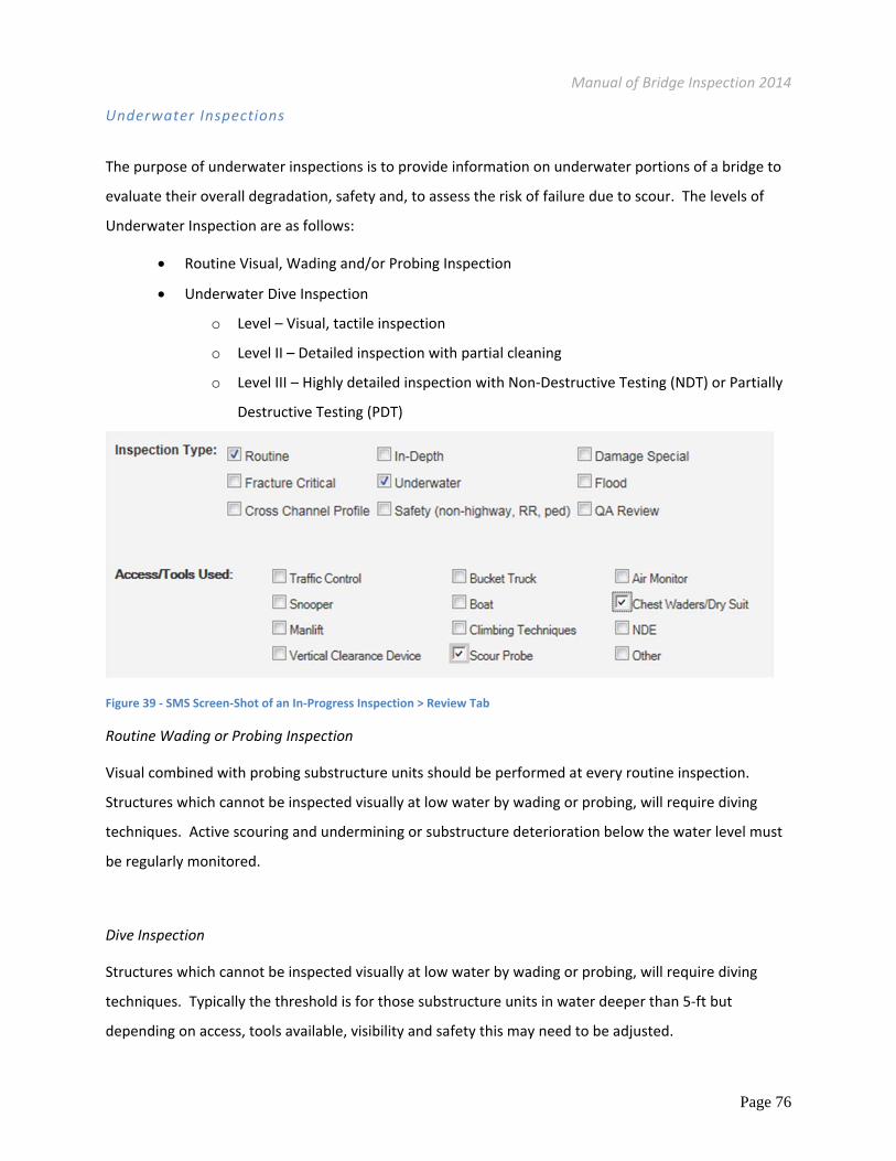
Figure 39 ‐ SMS Screen‐Shot of an In‐Progress Inspection > Review Tab
Routine Wading or Probing Inspection
Visual combined with probing substructure units should be performed at every routine inspection.
Structures which cannot be inspected visually at low water by wading or probing, will require diving
techniques. Active scouring and undermining or substructure deterioration below the water level must
be regularly monitored.
Dive Inspection
Structures which cannot be inspected visually at low water by wading or probing, will require diving
techniques. Typically the threshold is for those substructure units in water deeper than 5‐ft but
depending on access, tools available, visibility and safety this may need to be adjusted.

Manual of Bridge Inspection 2014
Page 77
Various factors influence the underwater bridge inspection selection criteria. All structures receive
routine underwater inspections at intervals not to exceed 60 months. This is the maximum interval
permitted between underwater inspections for bridges which are in excellent underwater condition and
which are located in passive, nonthreatening environments. The control authority determines the
inspection interval that is appropriate for each individual bridge. This is generally considered to be a
water depth that prevents an inspector from safely probing around the culvert, pier or abutment.
Factors to consider in establishing the inspection frequency and levels of inspection include:
Inspector Access
Inspector Safety
Age of Structure & Substructure
Traffic volume
Size of Structure
Susceptibility to collision
Extent of deterioration
Performance history of bridge type
Load rating
Location
National defense designation
Detour length
Social and economic impacts due to the
bridge being out of service
Type of construction materials
Environment
Scour characteristics
Condition ratings from past inspections
Known deficiencies
Non‐destructive technology, including ground sensing radar, ultrasonic techniques, remote video
recorders, and others are useful aids to supplement, but not replace, underwater inspections of
substructure foundations.
Key information to be determined in every underwater dive inspection is the top of streambed relative
to the elevation of the substructure foundations. Because scour can vary significantly from one end of a
footing to the other, a single probing reading is not sufficient. Baseline streambed conditions should be
established by waterway opening cross sections and by a grid pattern of probing readings around the
face of a substructure unit. This baseline information is essential for future monitoring and assessment.
The current streambed conditions and changes since the last inspection are critical inputs to the bridge
scour assessment.
Each bridge should have a local reference point established near each substructure unit to enable
Inspectors to quickly and accurately determine the depth of adjacent scour. These can be as simple as a
Manual of Bridge Inspection 2014
Page 78
painted line or PK nail driven into the wall in a place visible during high water. The location of these
scour‐monitoring benchmarks should be referenced in the inspection records and bridge file. Use
previously established benchmarks when possible to provide a long‐term record of scour conditions. If
new benchmarks need to be established, provide conversion from new to old datum.
Underwater inspections are intended to investigate two critical issues regarding the condition of bridge
substructures located in water:
The condition of structural components (including pier shaft, abutment walls, footings, etc.)
under water.
The integrity of the substructure foundation (including underlying soil, piles, caissons, etc.)
against scour at each substructure unit in water.
The inspection of the foundation of a substructure unit and the determination of its ongoing resistance
to scour is critical for the overall safety of the bridge. Because the integrity of the foundation against
scour can suddenly and dramatically change in a relatively short time (as compared to physical condition
of the structure components), shorter intervals for inspection of the foundation should be established
when warranted.
Scope for an Underwater Dive Inspection
A regularly scheduled Underwater Dive Inspection normally includes a 100% Level I inspection and a
10% Level II inspection. It may also include additional Level II inspections and Level III inspection if
necessary to determine the structural condition of the submerged substructure elements with certainty
Level I Underwater Dive Bridge Inspection includes a close visual examination of the entire submerged
portions of a bridge. They should include, but are not limited to the following:
Written Inspection Procedures specific to the bridge
Steel, concrete, stone & timber abutments, piers, fenders, and dolphins
Identify and describe any scour adjacent to the above mentioned items.
Identify and describe any damage to substructure items as may have been caused by collision
(ice, debris, vessels, vehicles, etc).
Identify and describe any footings or support elements which may be exposed.
If bottoms of footings are exposed, include measurements describing the sizes of voids under
the footings. In addition, describe the condition of any piling exposed in the void area.
Manual of Bridge Inspection 2014
Page 79
Identify and describe the condition of all piling of pile supported structures from the waterline
to channel bottom, and identify and describe the condition of any pile protection.
Identify and describe any cracks, scaling, tilting, or spalling of concrete or masonry piers and
abutments.
Probing of the soil adjacent to any substructure unit is required
Cross Channel Profile (if applicable): Discussed later in this chapter.
Scour Susceptibility Inspection and Evaluation (if applicable): Discussed later in this chapter.
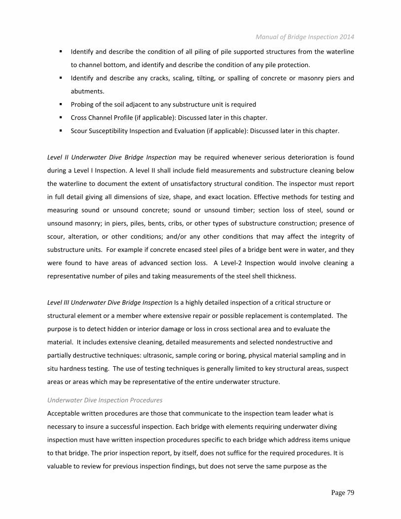
Level II Underwater Dive Bridge Inspection may be required whenever serious deterioration is found
during a Level I Inspection. A level II shall include field measurements and substructure cleaning below
the waterline to document the extent of unsatisfactory structural condition. The inspector must report
in full detail giving all dimensions of size, shape, and exact location. Effective methods for testing and
measuring sound or unsound concrete; sound or unsound timber; section loss of steel, sound or
unsound masonry; in piers, piles, bents, cribs, or other types of substructure construction; presence of
scour, alteration, or other conditions; and/or any other conditions that may affect the integrity of
substructure units. For example if concrete encased steel piles of a bridge bent were in water, and they
were found to have areas of advanced section loss. A Level‐2 Inspection would involve cleaning a
representative number of piles and taking measurements of the steel shell thickness.
Level III Underwater Dive Bridge Inspection Is a highly detailed inspection of a critical structure or
structural element or a member where extensive repair or possible replacement is contemplated. The
purpose is to detect hidden or interior damage or loss in cross sectional area and to evaluate the
material. It includes extensive cleaning, detailed measurements and selected nondestructive and
partially destructive techniques: ultrasonic, sample coring or boring, physical material sampling and in
situ hardness testing. The use of testing techniques is generally limited to key structural areas, suspect
areas or areas which may be representative of the entire underwater structure.
Underwater Dive Inspection Procedures
Acceptable written procedures are those that communicate to the inspection team leader what is
necessary to insure a successful inspection. Each bridge with elements requiring underwater diving
inspection must have written inspection procedures specific to each bridge which address items unique
to that bridge. The prior inspection report, by itself, does not suffice for the required procedures. It is
valuable to review for previous inspection findings, but does not serve the same purpose as the
Manual of Bridge Inspection 2014
Page 80
inspection procedures. The inspection report records what an inspector actually did, what was looked
at, and what was found. Procedures lay out what should be done, looked at, etc. The procedure
checklist in Appendix is a framework to satisfy the intent of the FHWA requirements. The procedures
can be incorporated into the inspection report in SMS “Review” tab.
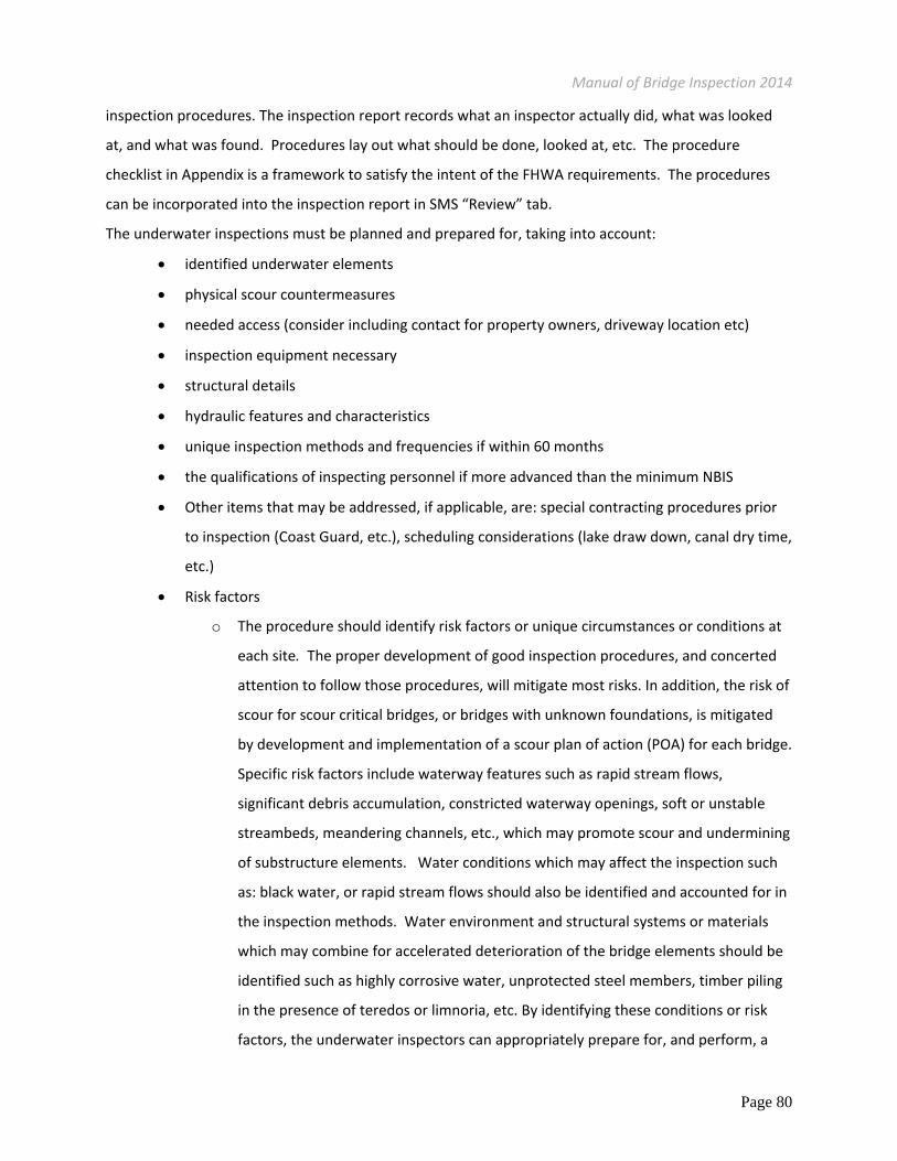
The underwater inspections must be planned and prepared for, taking into account:
identified underwater elements
physical scour countermeasures
needed access (consider including contact for property owners, driveway location etc)
inspection equipment necessary
structural details
hydraulic features and characteristics
unique inspection methods and frequencies if within 60 months
the qualifications of inspecting personnel if more advanced than the minimum NBIS
Other items that may be addressed, if applicable, are: special contracting procedures prior
to inspection (Coast Guard, etc.), scheduling considerations (lake draw down, canal dry time,
etc.)
Risk factors
o The procedure should identify risk factors or unique circumstances or conditions at
each site. The proper development of good inspection procedures, and concerted
attention to follow those procedures, will mitigate most risks. In addition, the risk of
scour for scour critical bridges, or bridges with unknown foundations, is mitigated
by development and implementation of a scour plan of action (POA) for each bridge.
Specific risk factors include waterway features such as rapid stream flows,
significant debris accumulation, constricted waterway openings, soft or unstable
streambeds, meandering channels, etc., which may promote scour and undermining
of substructure elements. Water conditions which may affect the inspection such
as: black water, or rapid stream flows should also be identified and accounted for in
the inspection methods. Water environment and structural systems or materials
which may combine for accelerated deterioration of the bridge elements should be
identified such as highly corrosive water, unprotected steel members, timber piling
in the presence of teredos or limnoria, etc. By identifying these conditions or risk
factors, the underwater inspectors can appropriately prepare for, and perform, a

Manual of Bridge Inspection 2014
Page 81
thorough inspection. The underwater inspection procedures developed for the
bridge should adequately address these items, and also whether the inspection
reports adequately address them, as appropriate.
Cross Channel Profile
Cross channel profile measurements are taken on bridges over waterways to track the rate‐of‐change of
stream alignment and scour. Soundings of the channel bottom are usually done along the bridge
centerline (to depict any areas of scour). Soundings will be made at a maximum interval (ex. 10’spacing)
and the channel bottom elevations shall be compared with pier or abutment elevations. Additional
soundings around piers and abutments, both up and downstream should be taken as necessary to
accurately depict any areas of scour. River current direction should be shown on the sounding diagram.
Additional resources should be assigned to complete cross channel profiles, see Appendix. Cross
Channel Profile Measurements and the SMS Cross Channel Form in order to chart the rate of change of
scour and channel embankments.
Scour Susceptibility Inspection and Evaluation
Scour Susceptibility Inspection and Analysis evaluations are performed to determine the level of risk
associated with hydraulic events. A full Evaluation includes a Data Review, a Field Inspection and an
Engineering Evaluation. The level of effort at each site will depend on the availability of information
collected.
Figure 40 ‐ Cross Channel Profile
Manual of Bridge Inspection 2014
Page 82
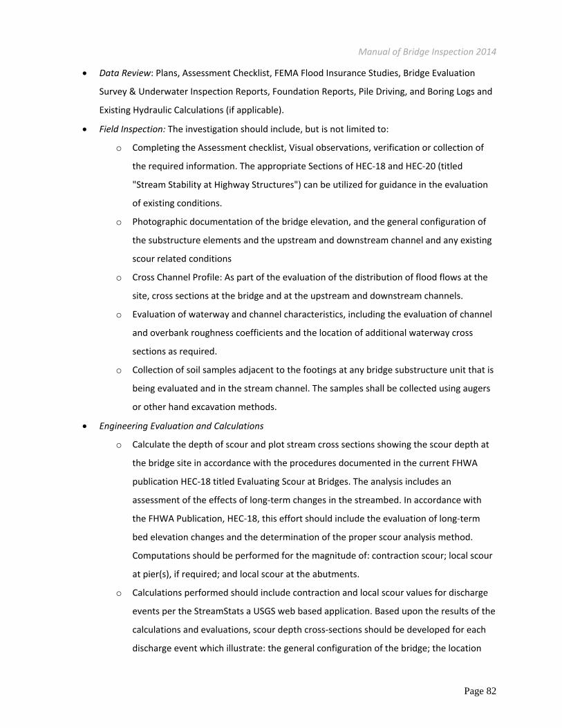
Data Review: Plans, Assessment Checklist, FEMA Flood Insurance Studies, Bridge Evaluation
Survey & Underwater Inspection Reports, Foundation Reports, Pile Driving, and Boring Logs and
Existing Hydraulic Calculations (if applicable).
Field Inspection: The investigation should include, but is not limited to:
o Completing the Assessment checklist, Visual observations, verification or collection of
the required information. The appropriate Sections of HEC‐18 and HEC‐20 (titled
"Stream Stability at Highway Structures") can be utilized for guidance in the evaluation
of existing conditions.
o Photographic documentation of the bridge elevation, and the general configuration of
the substructure elements and the upstream and downstream channel and any existing
scour related conditions
o Cross Channel Profile: As part of the evaluation of the distribution of flood flows at the
site, cross sections at the bridge and at the upstream and downstream channels.
o Evaluation of waterway and channel characteristics, including the evaluation of channel
and overbank roughness coefficients and the location of additional waterway cross
sections as required.
o Collection of soil samples adjacent to the footings at any bridge substructure unit that is
being evaluated and in the stream channel. The samples shall be collected using augers
or other hand excavation methods.
Engineering Evaluation and Calculations
o Calculate the depth of scour and plot stream cross sections showing the scour depth at
the bridge site in accordance with the procedures documented in the current FHWA
publication HEC‐18 titled Evaluating Scour at Bridges. The analysis includes an
assessment of the effects of long‐term changes in the streambed. In accordance with
the FHWA Publication, HEC‐18, this effort should include the evaluation of long‐term
bed elevation changes and the determination of the proper scour analysis method.
Computations should be performed for the magnitude of: contraction scour; local scour
at pier(s), if required; and local scour at the abutments.
o Calculations performed should include contraction and local scour values for discharge
events per the StreamStats a USGS web based application. Based upon the results of the
calculations and evaluations, scour depth cross‐sections should be developed for each
discharge event which illustrate: the general configuration of the bridge; the location

Manual of Bridge Inspection 2014
Page 83
and depth of the bridge foundations; and the depths of the various scour components
(long term, contraction, local) Based upon these cross‐sections, the existing
substructure units can be evaluated/analyzed for horizontal and vertical stability. The
depths of scour should be evaluated/analyzed for reasonableness based upon actual
records for storms and/or scour holes and the potential effect of lateral stability of the
waterway.
Special/Interim/Miscellaneous Inspections
Special (or Interim) Inspections are scheduled by the bridge Owner to examine bridges or portions of
bridges with known or suspected deficiencies. Special Inspections tend to focus on specific areas of a
bridge where problems were previously reported or to investigate areas where problems are suspected.
Special Inspections are conducted until corrective actions remove critical deficiencies or until the risk is
diminished.
Purpose of Special/Interim Inspections
Special Inspections are used to monitor particular known or suspected critical deficiencies, fulfill the
need for interim inspections (i.e. reduced inspection interval for posted bridges, repairs), and to
investigate bridge conditions following a natural disaster or manmade emergency.
Scope and Frequency of Special/Interim Inspections
The Program Manager defines the scope and frequency of the Special Inspections. The personnel
performing a Special Inspection should be carefully instructed regarding the nature of the known
deficiency and its functional relationship to satisfactory bridge performance. Guidelines and procedures
on what to observe and/or measure must be provided.
The determination of an appropriate scope and frequency for a Special Inspection frequency should
consider the nature, severity and extent of the known deficiency, as well as age, traffic characteristics,
public importance, and maintenance history. Special Inspections are typically at intervals shorter than 12
months.

Manual of Bridge Inspection 2014
Page 84
Safety (Cursory) Inspection
Safety inspections are similar to routine inspections but are more cursory in nature. They are secondary
inspections performed by entities that do not have primary inspection responsibility per State regulation
but that have a vested interest in the safety of the traveling public on or under the structures.
Non‐Highway bridges over a highway: Those
entities with right‐of‐way underneath the bridge
should be inventory and annually inspect such
structures to ensure such structures do not pose
an unacceptable safety risk. Such inspections
should only consist of those portions of the
structure which would directly affect the right‐of‐
way underneath the structure. Any problems
requiring immediate attention should be relayed
to the responsible authorities.
Closed bridges: When a public road bridge is closed to vehicular traffic but not removed from the site,
continued cursory inspections are required on an annual basis to assure adequate safety to the public
having access on or beneath the structure, and that necessary barricades for vehicles and/or pedestrians
are in place.
If a bridge remains on the inventory of public roads, it must be inspected in accordance with NBIS and
Department standards. Although a bridge is closed, the inspection must be current. Federal‐aid funding
eligibility is not maintained without current inspection records (note: the Operational Status on the
report must be coded “X” or “K” to indicate the structure is closed).
Figure 42 ‐ Overhead Pedestrian Non‐Highway Structure
Figure 41 ‐ Overhead Conveyer Structure

Manual of Bridge Inspection 2014
Page 85
Coordination with Railroad Bridges over a Public Highway:
Railroad track owners are responsible for an annual inspection per Federal Regulation (49 CFR part 237
eff. July 15, 2010). Not performing inspections may result in tickets or fines, anywhere between $650 to
$25,000, from FRA inspectors. ORC requires that annual inspection reports are submitted to:
Public Utility Commission of Ohio (PUCO) and
The public authority with jurisdiction of the highway (ORC 4907.44), when dangerous conditions
exist
In the event reports are not
submitted to the public authority a
request may be filed with the track
owner in order to receive such
reports. Safety (or Cursory)
inspections should be performed by
the public authority with jurisdiction
of the highway to ensure the safety
of the traveling public. This includes
an inventory of the portion of the
structure in the right‐of‐way.
Track owners are responsible not only for inspecting but for performing maintenance (ORC 5523.17 eff.
9/28/1973, ORC 4955.20 eff. 10/1/1953). Track‐owners are required to report to the Public Utility
Commission (PUCO) unsafe structures that require speed reductions (ORC 4907.45 eff. 10/1/1953) and
annual inspection reports (ORC 4907.44 eff. 6/11/1968). Additionally, if the obstruction or properties
present an immediate and serious threat to the safety of the traveling public, the ODOT director may
remove or relocate the obstruction or properties without prior notice (ORC 5515.02 eff. 4/5/2001).
Quality Assurance (QA) Review Inspection
Established QA Inspections are regularly performed on bridges by representatives from FHWA, CEAO or
ODOT central office to promote accuracy and consistency and to ensure NBIS Compliance. The Control
Authority of each entity is encouraged to perform sample inspections in addition to the independent
field reviews prescribed in Metric 20.
Table 32 ‐ Railroad Bridge Over Highway ROW

Manual of Bridge Inspection 2014
Page 86
Complex Bridge Inspections
Complex Bridges include structures
with suspension bridges, movable
bridges and cable stayed bridges.
These unique or special features
necessitate additional inspection
requirements and inspector duties.
The inspection of a Complex bridge
must be in accordance with this
Manual of Bridge Inspection, the
FHWA Bridge Inspectors Reference
Manual (BIRM). Additionally every
complex bridge should have its own
Operating and Maintenance
Manual and Field Inspection Plan.
If there is no Operating and
Maintenance Manual, then sound
judgment should be used in establishing a thorough Field Inspection Plan where specific conditions are
encountered that are not covered by this manual or the BIRM.
Due to the size and/or complexity of the bridge, a good field inspection plan is necessary to ensure
historical continuity, track deficiencies and communicate nomenclature. A good inspection plan should
include most of the following:
The type of Inspection(s) to be completed
A brief historical fact statement about the bridge type and condition
Confirmation that the bridge has been properly cleaned for the type of inspection planned
Copies of essential plans
A mapped route to the site
Keys for any locked access points
Specialized inspection procedures which clearly identify the complex features
Frequency of inspection of those features
Describe any specific risk factors unique to the bridge
Figure 43 ‐ Complex Inspection 1

Manual of Bridge Inspection 2014
Page 87
Clearly detail inspection methods and equipment to be employed.
Identification of tension members and fatigue‐prone details, failure prone details and fracture
critical members or member components
Identification of access equipment and arrangements for them to be on‐site
Identification of required nondestructive testing (NDT) equipment and arrangements for it to be
on‐site
Identification of traffic control requirements and arrangements for on‐site implementation
Press releases, if necessary
Inspection time estimate
Coordination with the owner and other agencies as required
On larger bridges it may be necessary to create individual sections for each of the required areas of the
inspection plan.
In addition to an operation and maintenance manual and a field inspection plan, the inspection team
leader will have additional qualifications. The
NBIS Team Leader who leads the field inspection
must meet the following requirements:
NBIS Team Leader
Familiarity with the type of complex
bridge to be inspected
Understanding of how the bridge
functions and where possible defects
might occur
Must be current on issues with the type
of bridges being inspected
Understanding and ability to perform
testing or recommend advanced testing
procedures at problem areas
Familiar with the Operating and
Maintenance Manual for the bridge
inspected and in charge with developing and implementing the Field Inspection Plan.
Figure 44 ‐ Complex Bridge Inspection 2

Manual of Bridge Inspection 2014
Page 88
Successfully passing training related to the type of complex bridge within the last ten years. For
example, the FHWA‐NHI‐130078, Fracture Critical Inspection Techniques for Steel Bridges, Non
Destructive Testing training etc.
Description: Complex Bridges
Complex bridges include the following:
Any Bridge Designated by the Program Manager
Suspension Bridges ‐ Bridges in which the floor systems are supported by catenary cables that
are supported upon towers and are anchored at their extreme ends (BIRM 12.1)
Cable Stayed Bridges ‐ Bridges in which the superstructures are directly supported by cables, or
stays, passing over or attached to towers located at the main piers (BIRM 12.1)
Movable Bridges ‐ Bridges having one or more spans capable of being raised, turned, lifted, or
slid from their normal service location to provide a clear navigation passage (BIRM 12.2)
Scope and Frequency of Complex
Bridge Inspections
The inspection frequency of complex
bridges varies depending on the type
and condition of each individual
component of the bridge. At a
minimum each bridge needs a routine
inspection every year, a fracture
critical inspection (when applicable)
every 24 months, an underwater
inspection (when applicable) every 60 months and a special inspection to monitor known deficiencies at
the discretion of the Program Manager. In depth inspections are recommended for Complex Bridges on
a 5‐year cycle or in accordance with the inspection and maintenance manual.
Figure 45 ‐ Inspector Rappelling the Cable Stay