INSPECT COMPONENTS PRIOR TO ERECTION Hire Shops · Regulations 1996 and BS 1139 Part 3 (HD 1004)....
2
Tower Components Boss Alloy Access Towers Hire Shops Designed to the European Standard HD1004, the BOSS Alloy Tower provides the ideal platform for light work. Two versions are available: 1450mm & 850mm wide each with either 1.8m or 2.5m deck lengths. Operating & Safety Guide 508 Code 80200/80300/80400/80700 508/04 This BOSS User Guide is designed to provide you with step by step instructions to ensure your system is erected easily and safely. Before assembly, please read the Safety Notes carefully. The law requires that operatives must be competent and qualified to erect the tower. If another person is involved, please pass on these instructions. For fuller information on the safe use of Mobile Access Towers consult the PASMA Guide. Complies with EN 1298. 2 RUNG FRAME END TOEBOARDS SIDE TOEBOARDS HORIZONTAL BRACE DIAGONAL BRACE LADDER FRAME SPAN FRAME ADJUSTABLE LEG STABILISER CASTOR PLATFORM (FIXED AND TRAP DOOR DECKS) INTRODUCTION INTERNAL USE ONLY 10.7m 11.2m 11.7m 12.2m 12.7m 13.2m 13.7m 14.2m 8.7m 9.2m 9.7m 10.2m 10.7m 11.2m 11.7m 12.2m 4 4 4 4 4 4 4 4 4 4 4 4 4 4 4 4 2 2 2 2 1 1 1 1 1 1 1 1 4 5 4 5 5 6 5 6 4 5 4 5 5 6 5 6 2 2 2 2 2 2 2 2 4 4 4 4 5 5 5 6 12 12 12 12 13 13 13 14 16 17 18 19 20 21 22 23 2 2 2 2 2 2 2 2 2 2 2 2 2 2 2 2 4 4 4 4 4 4 4 4 4 4 4 4 4 4 4 4 279 286 294 299 306 312 319 325 320 327 336 341 348 355 362 369 371 378 388 393 401 408 416 423 BALLAST: 1450 LADDERSPAN – Internal/External use. There is no requirement for ballast on 1450 towers if using stabilisers as detailed in the above table. If for internal use only, SP10 stabilisers may be fitted up to 10.7m platform height. STABILISERS To improve rigidity, larger stabilisers can be used at a lower level than shown in the table. NUMBER OF WORKING PLATFORMS ALLOWED The number of working levels is based on fully loading each single deck to the maximum of 275kg. A deck is defined as a single unit, but a working platform can be either one or two decks. The 275kg limit applies to each such working level, regardless of the number of decks. In normal circumstances only two such working levels are permissable, as with the taller structures/lengths self-weight will be a limiting factor. Maximum Safe Working Load for the tower structure is 950kg. Should heavier loads than these be required for particular applications, your local Branch will be able to provide guidance. The quantities above comply with the requirements of the Construction (Health, Safety & Welfare) Regulations 1996 and BS 1139 Part 3 (HD 1004). They include double handrailing to the rest platform level, and toeboards will need to be added if this is used as a working platform. Rest Platforms are required every 4m (per BS 1139 part 3) plus additional platforms for safe assembly. Should a fully decked rest platform be employed two additional handrails will be required. *Or 2 Rung ladder Frame NUMBER OF WORKING PLATFORMS ALLOWED The number of working levels is based on fully loading each single deck to the maximum of 275kg. A working platform can be either one or two decks, and the 275kg applies to each working level, regardless of whether one or two decks. The number of working levels will be limited by the total Safe Working Load of the tower. The Maximum Safe Working Load for the tower structures shown above is 950kg. For heights in excess of these, and for heavier loads, consult your local Branch for guidance. The quantities above comply with the requirements of the Construction (Health, Safety & Welfare) Regulations 1996 and BS 1139 Part 3 (HD 1004). They include double handrailing to the rest platform level, and toeboards will need to be added if this is used as a working platform. Rest Platforms are required every 4m (per BS 1139 part 3) plus additional platforms for safe assembly. Should a fully decked rest platform be employed two additional handrails will be required. *Or 2 Rung ladder Frame STABILISERS AND BALLAST: – Internal/External use. Stabiliser requirements are based on calculations from HD1004: 1. Up to 8.2m (Platform Height) the stabilisers and ballast are shown for external use. 2. Above 8.2m, the shedule is for internal use only. For internal use only, towers may be erected up to 12.5m without ballast, and SP10 stabilisers may be fitted up to 9.7m platform height. For greater rigidity, fit SP15 at lower height. STABILISERS To improve rigidity, larger stabilisers can be used at a lower level than shown in the table. INTERNAL/EXTERNAL USE DESCRIPTION WORKING HEIGHT 3.2m 3.7m 4.2m 4.7m 5.2m 5.7m 6.2m 6.7m 7.2m 7.7m 8.2m 8.7m 9.2m 9.7m 10.2m PLATFORM HEIGHT 1.2m 1.7m 2.2m 2.7m 3.2m 3.7m 4.2m 4.7m 5.2m 5.7m 6.2m 6.7m 7.2m 7.7m 8.2m 125/150/200mm CASTOR 4 4 4 4 4 4 4 4 4 4 4 4 4 4 4 250mm ADJUSTABLE LEG 4 4 4 4 4 4 4 4 4 4 4 4 4 4 4 1450 2 RUNG SPAN FRAME* 2 2 2 2 2 2 2 2 1450 3 RUNG LADDER FRAME 1 1 1 1 1 1 1 1450 3 RUNG SPAN FRAME 1 1 1 1 1 1 1 1450 4 RUNG LADDER FRAME 1 1 1 2 1 2 2 3 2 3 3 4 3 4 1450 4 RUNG SPAN FRAME 1 1 1 2 1 2 2 3 2 3 3 4 3 4 1.8/2.5/3.2m FIXED DECK 1 1 1 1 1 1 1 2 2 2 2 2 2 2 2 1.8/2.5/3.3m TRAP DOOR DECK 1 1 1 1 2 2 2 2 2 2 2 3 3 3 3 1.8/2.5/3.2m HORIZONTAL BRACE (RED) 6 6 6 6 8 8 8 10 10 10 10 11 11 11 11 2.1/2.7/3.4m DIAGONAL BRACE (BLUE) 2 3 3 4 5 6 7 8 9 10 11 12 13 14 15 1.8/2.5/3.2m SIDE TOEBOARD 2 2 2 2 2 2 2 2 2 2 2 2 2 2 2 1.2m END TOEBOARD 2 2 2 2 2 2 2 2 2 2 2 2 2 2 2 TOEBOARD HOLDER 4 4 4 4 4 4 4 4 4 4 4 4 4 4 4 SP10 TELESCOPIC STABILISER 4 4 4 4 4 4 4 4 4 SP15 TELESCOPIC STABILISER 4 4 4 4 TOTAL TOWER SELF-WEIGHT (KGS) 1.8m 92 98 102 110 170 179 183 208 215 223 228 235 241 250 272 TOTAL TOWER SELF-WEIGHT (KGS) 2.5m 108 115 119 127 158 167 171 239 246 253 260 268 275 284 312 TOTAL TOWER SELF-WEIGHT (KGS) 3.2m 128 135 140 148 188 198 203 242 250 257 264 309 316 327 362 QUANTITY SCHEDULE BOSS 1450 LADDERSPAN TO HD1004: AVAILABLE IN 3 LENGTHS – 1.8m, 2.5m & 3.2m INTERNAL USE ONLY 10.7m 11.2m 11.7m 12.2m 12.7m 13.2m 13.7m 14.2m 8.7m 9.2m 9.7m 10.2m 10.7m 11.2m 11.7m12.2mm 4 4 4 4 4 4 4 4 4 4 4 4 4 4 4 4 2 2 2 2 1 1 1 1 1 1 1 1 4 5 4 5 5 6 5 6 4 5 4 5 5 6 5 6 5 5 5 5 6 6 6 7 22 22 22 22 26 26 26 30 16 17 18 19 20 21 22 23 2 2 2 2 2 2 2 2 2 2 2 2 2 2 2 2 4 4 4 4 4 4 4 4 4 4 4 4 4 4 4 4 262 267 273 293 300 306 311 317 299 305 311 332 339 345 351 357 349 356 362 383 391 398 404 411 INTERNAL/EXTERNAL USE DESCRIPTION WORKING HEIGHT 3.2m 3.7m 4.2m 4.7m 5.2m 5.7m 6.2m 6.7m 7.2m 7.7m 8.2m 8.7m 9.2m 9.7m 10.2m PLATFORM HEIGHT 1.2m 1.7m 2.2m 2.7m 3.2m 3.7m 4.2m 4.7m 5.2m 5.7m 6.2m 6.7m 7.2m 7.7m 8.2m 125/150/200mm CASTOR 4 4 4 4 4 4 4 4 4 4 4 4 4 4 4 250mm ADJUSTABLE LEG 4 4 4 4 4 4 4 4 4 4 4 4 4 4 4 850 2 RUNG SPAN FRAME* 2 2 2 2 2 2 2 2 850 3 RUNG LADDER FRAME 1 1 1 1 1 1 1 850 3 RUNG SPAN FRAME 1 1 1 1 1 1 1 850 4 RUNG LADDER FRAME 1 1 1 2 1 2 2 3 2 3 3 4 3 4 850 4 RUNG SPAN FRAME 1 1 1 2 1 2 2 3 2 3 3 4 3 4 1.8/2.5/3.3m TRAP DOOR DECK 1 1 1 1 2 2 2 3 3 3 3 4 4 4 4 1.8/2.5/3.2m HORIZONTAL BRACE (RED) 6 6 6 6 10 10 10 14 14 14 14 18 18 18 18 2.1/2.7/3.4m DIAGONAL BRACE (BLUE) 2 3 3 4 5 6 7 8 9 10 11 12 13 14 15 1.8/2.5/3.2m SIDE TOEBOARD 2 2 2 2 2 2 2 2 2 2 2 2 2 2 2 0.6m END TOEBOARD 2 2 2 2 2 2 2 2 2 2 2 2 2 2 2 TOEBOARD HOLDER 4 4 4 4 4 4 4 4 4 4 4 4 4 4 4 SP10 TELESCOPIC STABILISER 4 4 4 4 4 4 4 4 4 SP15 TELESCOPIC STABILISER 4 4 4 4 BALLAST REQUIRED (KGS) 2.5m 25 50 75 BALLAST REQUIRED (KGS) 3.2m 25 50 100 125 TOTAL TOWER SELF-WEIGHT (KGS) 1.8m 73 78 108 115 142 148 153 195 201 206 212 233 239 242 269 TOTAL TOWER SELF-WEIGHT (KGS) 2.5m 84 90 119 127 161 167 173 222 228 234 240 262 291 321 381 TOTAL TOWER SELF-WEIGHT (KGS) 3.2m 98 104 134 142 187 193 200 259 266 272 279 326 355 411 481 BOSS 850 LADDERSPAN TO HD1004: AVAILABLE IN 3 LENGTHS – 1.8m, 2.5m & 3.2m CHECKLIST INSPECT COMPONENTS PRIOR TO ERECTION ❏ INSPECT TOWER PRIOR TO USE ❏ TOWER UPRIGHT ❏ CASTORS LOCKED/LEGS CORRECTLY ADJUSTED ❏ BRACES & PLATFORM LEVEL ❏ STABILISERS/OUTRIGGERS FITTED AS SPECIFIED ❏ PLATFORMS LOCATED & WINDLOCKS ON ❏ HANDRAILS IN PLACE ❏ TOEBOARDS LOCATED ❏ REFER TO THIS CHECKLIST BEFORE USING EACH TIME Fitting Toeboards Lock yellow plastic toeboard clips over rung and deck claw as shown. Position as (A) on right hand deck claw. On other side of working platform position as (B). Place 25mm thick toeboards into slots in toeboard clips as shown. TOEBOARD CLIP TOEBOARD CLAW RUNG DECK A B STABILITY: STABILISERS & OUTRIGGERS Stabilisers are used when the tower is to be used occasionally, frequent use will require Outriggers. Attach one stabiliser to each corner of the tower at approx. 45 degrees. secure top clamp below castings, bottom clamp as low as possible. If Clamp is obstructed, release and move. Ensure clamps are rigidly fixed to limit movement. With SP10 and SP15 Stabilisers, extend telescopic leg until in contact with ground. When moving, check for obstructions and lock feet about 25mm off the ground, unlock castors, and move. After moving, check all castors are in ground contact and lock Stabiliser feet. SP10 SP15 250 2500 850 4914 1450 5688 SP7 250 1900 1227 250 850 2586 1450 3186 850 3939 1450 4671 ©HSS Hire Service Group Ltd 2004 No. 508/04 Group Office: 25 Willow Lane, Mitcham, Surrey CR4 4TS Web Site: http://www.hss.co.uk …any comments? If you have any suggestions to enable us to improve the information within this guide please fax your comments or write to the Product Manager at the address below Fax: 020 887 5001
Transcript of INSPECT COMPONENTS PRIOR TO ERECTION Hire Shops · Regulations 1996 and BS 1139 Part 3 (HD 1004)....
Tower Components
Boss AlloyAccess Towers
Hire Shops
Designed to the European StandardHD1004, the BOSS Alloy Tower
provides the ideal platform for lightwork. Two versions are available:
1450mm & 850mm wide each witheither 1.8m or 2.5m deck lengths.
Operating & Safety Guide 508
Code 80200/80300/80400/80700
508/
04
This BOSS User Guide is designed to provide you with step bystep instructions to ensure your system is erected easily andsafely. Before assembly, please read the Safety Notes carefully. The law requires that operatives must be competent andqualified to erect the tower. If another person is involved, pleasepass on these instructions.For fuller information on the safe use of Mobile Access Towersconsult the PASMA Guide. Complies with EN 1298.
2 RUNGFRAME
ENDTOEBOARDS
SIDETOEBOARDS
HORIZONTALBRACE
DIAGONALBRACE
LADDER FRAME
SPAN FRAME
ADJUSTABLE LEG
STABILISER
CASTOR
PLATFORM(FIXED ANDTRAP DOOR
DECKS)
INTRODUCTION INTERNAL USE ONLY10.7m 11.2m 11.7m 12.2m 12.7m 13.2m 13.7m 14.2m
8.7m 9.2m 9.7m 10.2m 10.7m 11.2m 11.7m 12.2m
4 4 4 4 4 4 4 44 4 4 4 4 4 4 4
2 2 2 21 1 1 11 1 1 14 5 4 5 5 6 5 64 5 4 5 5 6 5 62 2 2 2 2 2 2 24 4 4 4 5 5 5 6
12 12 12 12 13 13 13 1416 17 18 19 20 21 22 23
2 2 2 2 2 2 2 22 2 2 2 2 2 2 24 4 4 4 4 4 4 4
4 4 4 4 4 4 4 4
279 286 294 299 306 312 319 325320 327 336 341 348 355 362 369371 378 388 393 401 408 416 423
BALLAST: 1450 LADDERSPAN – Internal/External use. There is no requirement forballast on 1450 towers if using stabilisers as detailed in the above table. If for internaluse only, SP10 stabilisers may be fitted up to 10.7m platform height.STABILISERSTo improve rigidity, larger stabilisers can be used at a lower level than shown in the table.
NUMBER OF WORKING PLATFORMS ALLOWEDThe number of working levels is based on fully loading each single deck to the maximum of 275kg. A deck is defined as a single unit, but a working platformcan be either one or two decks. The 275kg limit applies to each such working level, regardless ofthe number of decks.In normal circumstances only two such working levels are permissable, as with the tallerstructures/lengths self-weight will be a limiting factor.Maximum Safe Working Load for the tower structure is 950kg. Should heavier loads than these be required for particular applications, your local Branch will beable to provide guidance.The quantities above comply with the requirements of the Construction (Health, Safety & Welfare)Regulations 1996 and BS 1139 Part 3 (HD 1004). They include double handrailing to the restplatform level, and toeboards will need to be added if this is used as a working platform.Rest Platforms are required every 4m (per BS 1139 part 3) plus additional platforms for safe assembly.Should a fully decked rest platform be employed two additional handrails will be required.*Or 2 Rung ladder Frame
NUMBER OF WORKING PLATFORMS ALLOWEDThe number of working levels is based on fully loading each single deck to the maximum of 275kg.A working platform can be either one or two decks, and the 275kg applies to each working level,regardless of whether one or two decks.The number of working levels will be limited by the total Safe Working Load of the tower.The Maximum Safe Working Load for the tower structures shown above is 950kg. For heights inexcess of these, and for heavier loads, consult your local Branch for guidance.The quantities above comply with the requirements of the Construction (Health, Safety & Welfare)Regulations 1996 and BS 1139 Part 3 (HD 1004). They include double handrailing to the restplatform level, and toeboards will need to be added if this is used as a working platform.Rest Platforms are required every 4m (per BS 1139 part 3) plus additional platforms for safe assembly.Should a fully decked rest platform be employed two additional handrails will be required.*Or 2 Rung ladder Frame
STABILISERS AND BALLAST: – Internal/External use. Stabiliser requirements are basedon calculations from HD1004:1. Up to 8.2m (Platform Height) the stabilisers and ballast are shown for external use.2. Above 8.2m, the shedule is for internal use only.For internal use only, towers may be erected up to 12.5m without ballast, and SP10 stabilisersmay be fitted up to 9.7m platform height. For greater rigidity, fit SP15 at lower height.STABILISERSTo improve rigidity, larger stabilisers can be used at a lower level than shown in the table.
INTERNAL/EXTERNAL USEDESCRIPTION WORKING HEIGHT 3.2m 3.7m 4.2m 4.7m 5.2m 5.7m 6.2m 6.7m 7.2m 7.7m 8.2m 8.7m 9.2m 9.7m 10.2m
PLATFORM HEIGHT 1.2m 1.7m 2.2m 2.7m 3.2m 3.7m 4.2m 4.7m 5.2m 5.7m 6.2m 6.7m 7.2m 7.7m 8.2m
125/150/200mm CASTOR 4 4 4 4 4 4 4 4 4 4 4 4 4 4 4250mm ADJUSTABLE LEG 4 4 4 4 4 4 4 4 4 4 4 4 4 4 41450 2 RUNG SPAN FRAME* 2 2 2 2 2 2 2 21450 3 RUNG LADDER FRAME 1 1 1 1 1 1 11450 3 RUNG SPAN FRAME 1 1 1 1 1 1 11450 4 RUNG LADDER FRAME 1 1 1 2 1 2 2 3 2 3 3 4 3 41450 4 RUNG SPAN FRAME 1 1 1 2 1 2 2 3 2 3 3 4 3 41.8/2.5/3.2m FIXED DECK 1 1 1 1 1 1 1 2 2 2 2 2 2 2 21.8/2.5/3.3m TRAP DOOR DECK 1 1 1 1 2 2 2 2 2 2 2 3 3 3 31.8/2.5/3.2m HORIZONTAL BRACE (RED) 6 6 6 6 8 8 8 10 10 10 10 11 11 11 112.1/2.7/3.4m DIAGONAL BRACE (BLUE) 2 3 3 4 5 6 7 8 9 10 11 12 13 14 151.8/2.5/3.2m SIDE TOEBOARD 2 2 2 2 2 2 2 2 2 2 2 2 2 2 21.2m END TOEBOARD 2 2 2 2 2 2 2 2 2 2 2 2 2 2 2TOEBOARD HOLDER 4 4 4 4 4 4 4 4 4 4 4 4 4 4 4
SP10 TELESCOPIC STABILISER 4 4 4 4 4 4 4 4 4SP15 TELESCOPIC STABILISER 4 4 4 4
TOTAL TOWER SELF-WEIGHT (KGS) 1.8m 92 98 102 110 170 179 183 208 215 223 228 235 241 250 272TOTAL TOWER SELF-WEIGHT (KGS) 2.5m 108 115 119 127 158 167 171 239 246 253 260 268 275 284 312TOTAL TOWER SELF-WEIGHT (KGS) 3.2m 128 135 140 148 188 198 203 242 250 257 264 309 316 327 362
QUANTITY SCHEDULE BOSS 1450 LADDERSPAN TO HD1004: AVAILABLE IN 3 LENGTHS – 1.8m, 2.5m & 3.2m
INTERNAL USE ONLY 10.7m 11.2m 11.7m 12.2m 12.7m 13.2m 13.7m 14.2m
8.7m 9.2m 9.7m 10.2m 10.7m 11.2m 11.7m12.2mm
4 4 4 4 4 4 4 44 4 4 4 4 4 4 4
2 2 2 21 1 1 11 1 1 14 5 4 5 5 6 5 64 5 4 5 5 6 5 65 5 5 5 6 6 6 7
22 22 22 22 26 26 26 3016 17 18 19 20 21 22 23
2 2 2 2 2 2 2 22 2 2 2 2 2 2 24 4 4 4 4 4 4 4
4 4 44 4 4 4 4
262 267 273 293 300 306 311 317299 305 311 332 339 345 351 357349 356 362 383 391 398 404 411
INTERNAL/EXTERNAL USEDESCRIPTION WORKING HEIGHT 3.2m 3.7m 4.2m 4.7m 5.2m 5.7m 6.2m 6.7m 7.2m 7.7m 8.2m 8.7m 9.2m 9.7m 10.2m
PLATFORM HEIGHT 1.2m 1.7m 2.2m 2.7m 3.2m 3.7m 4.2m 4.7m 5.2m 5.7m 6.2m 6.7m 7.2m 7.7m 8.2m
125/150/200mm CASTOR 4 4 4 4 4 4 4 4 4 4 4 4 4 4 4250mm ADJUSTABLE LEG 4 4 4 4 4 4 4 4 4 4 4 4 4 4 4850 2 RUNG SPAN FRAME* 2 2 2 2 2 2 2 2850 3 RUNG LADDER FRAME 1 1 1 1 1 1 1850 3 RUNG SPAN FRAME 1 1 1 1 1 1 1850 4 RUNG LADDER FRAME 1 1 1 2 1 2 2 3 2 3 3 4 3 4850 4 RUNG SPAN FRAME 1 1 1 2 1 2 2 3 2 3 3 4 3 41.8/2.5/3.3m TRAP DOOR DECK 1 1 1 1 2 2 2 3 3 3 3 4 4 4 41.8/2.5/3.2m HORIZONTAL BRACE (RED) 6 6 6 6 10 10 10 14 14 14 14 18 18 18 182.1/2.7/3.4m DIAGONAL BRACE (BLUE) 2 3 3 4 5 6 7 8 9 10 11 12 13 14 151.8/2.5/3.2m SIDE TOEBOARD 2 2 2 2 2 2 2 2 2 2 2 2 2 2 20.6m END TOEBOARD 2 2 2 2 2 2 2 2 2 2 2 2 2 2 2TOEBOARD HOLDER 4 4 4 4 4 4 4 4 4 4 4 4 4 4 4
SP10 TELESCOPIC STABILISER 4 4 4 4 4 4 4 4 4SP15 TELESCOPIC STABILISER 4 4 4 4
BALLAST REQUIRED (KGS) 2.5m 25 50 75BALLAST REQUIRED (KGS) 3.2m 25 50 100 125
TOTAL TOWER SELF-WEIGHT (KGS) 1.8m 73 78 108 115 142 148 153 195 201 206 212 233 239 242 269TOTAL TOWER SELF-WEIGHT (KGS) 2.5m 84 90 119 127 161 167 173 222 228 234 240 262 291 321 381TOTAL TOWER SELF-WEIGHT (KGS) 3.2m 98 104 134 142 187 193 200 259 266 272 279 326 355 411 481
BOSS 850 LADDERSPAN TO HD1004: AVAILABLE IN 3 LENGTHS – 1.8m, 2.5m & 3.2m
CHECKLIST
INSPECT COMPONENTS PRIOR TO ERECTION ❏INSPECT TOWER PRIOR TO USE ❏TOWER UPRIGHT ❏CASTORS LOCKED/LEGS CORRECTLY ADJUSTED ❏BRACES & PLATFORM LEVEL ❏STABILISERS/OUTRIGGERS FITTED AS SPECIFIED ❏PLATFORMS LOCATED & WINDLOCKS ON ❏HANDRAILS IN PLACE ❏TOEBOARDS LOCATED ❏REFER TO THIS CHECKLIST BEFORE USING EACH TIME
Fitting ToeboardsLock yellow plastic toeboard clips over rung and deck claw as shown. Position as (A) on right hand deck claw.On other side of working platform position as (B). Place25mm thick toeboards into slots in toeboard clips as shown.
TOEBOARD CLIP
TOEBOARD
CLAW
RUNG
DECK
A
B
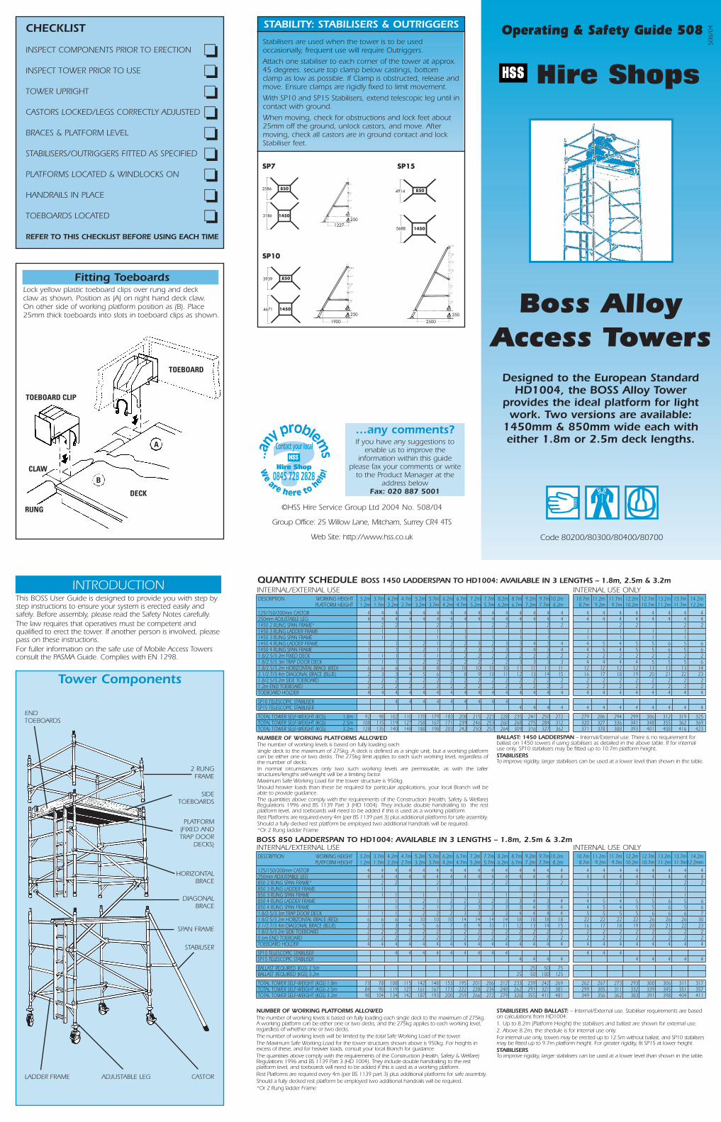
STABILITY: STABILISERS & OUTRIGGERS
Stabilisers are used when the tower is to be usedoccasionally, frequent use will require Outriggers.
Attach one stabiliser to each corner of the tower at approx.45 degrees. secure top clamp below castings, bottomclamp as low as possible. If Clamp is obstructed, release andmove. Ensure clamps are rigidly fixed to limit movement.
With SP10 and SP15 Stabilisers, extend telescopic leg until incontact with ground.
When moving, check for obstructions and lock feet about25mm off the ground, unlock castors, and move. Aftermoving, check all castors are in ground contact and lockStabiliser feet.
SP10
SP15
250
2500
8504914
14505688
SP7
250
1900
1227250
8502586
14503186
8503939
14504671
©HSS Hire Service Group Ltd 2004 No. 508/04
Group Office: 25 Willow Lane, Mitcham, Surrey CR4 4TS
Web Site: http://www.hss.co.uk
…any comments?If you have any suggestions to
enable us to improve theinformation within this guide
please fax your comments or writeto the Product Manager at the
address below Fax: 020 887 5001
Now clipdiagonalDiagonalBraces (blue)onto lowestrungs, inopposingdirections.Adjust legs withspirit level orsimilar.
LOCKED
ASSEMBLY PRINCIPLES
WHEN BUILDING A BOSS TOWER:● To comply with the Work at Height
Regulations we show procedures withadditional platforms and the locating ofsingle Guardrails when building inadvance of climbing onto a platform toreduce the risk of a fall. This involvesmoving components, but is an importantprocedure for your safety.
● Always stand on a Boss Platform, never onthe rungs of a Frame.
● Install temporary single Guardrails prior toclimbing onto platforms, from the platformstaggered below. Working platforms andrest platforms (every 4 metres) requiredouble Guardrails. All working levelsrequire toeboards.
● Stagger platforms to the left or right at 1metre intervals,which will limit the potentialheight of fall.
● Locate single Guardrail (Horizontal Braces)from below in advance of climbing ontothe platform.
DISMANTLING PRINCIPLES
TO DISMANTLE A BOSS TOWER:● Remove toeboards, and pass down the
tower.
1450 TOWER● From 2 metres below, both operatives
should remove upper fixed platform.Relocate to 1 metre below working level,installing single Guardrail removed fromupper working platform.
● Platforms used for erection purposes should beSingle-Guardrailed.
● Stagger all platform positions at 1m intervals.
● Remove uppermost platform and remainingGuardrails and pass down to position 1 metrebelow lowest platform.
850 TOWERFollow same procedure, but with Trapdoorplatforms, and dismantle from 2 metresbelow.
GENERAL NOTE
The assembly procedure from nowon should be based on:● Always stand on a BOSS
platform, never on the rungs ofa frame.
● Install platforms at 1 metrevertical intervals, to give amanageable reach height,staggering platforms to the leftor right to limit any potentialheight of fall.
● Locate single Guardrail(Horizontal Braces) in advance ofclimbing onto the platform, at1.0m (2 rungs) height.
● Rest platforms require 2 xGuardrails.
● Always position Trapdoors overLadder side, and Fixed Platformson opposite side.
Positions for Platforms asassembly progresses. (Stabilisersomitted for clarity)
Unlocked
Locked
= Fixed Deck
= Trapdoor Deck
= Fixed Deck
= Trapdoor Deck
Rung
8
67
5
34
1
2
850 ASSEMBLY - see Assembly Principles USAGE ADVICE
DURING USE● Beware of high winds in exposed, gusty or
medium breeze conditions. We recommendthat in wind speeds over 7.7 metres persecond (17 m.p.h.), cease working on thetower. If the wind becomes a strong breeze,expected to reach 11.3 metres per second (25m.p.h.), tie the tower to a rigid structure. If thewind is likely to reach gale force, over 18 metresper second (40 m.p.h.), the tower should bedismantled.
Wind Beaufort Beaufort Speed in Speed inDescription Scale No. m.p.h. m/sec.Medium Breeze Raises dust and loose 4 8-12 4-6
paper, twigs snap off.Strong Breeze Large branches in motion, 6 25-31 11-14
telegraph wires whistle.Gale Force Walking is difficult. 8 39-46 17-21
Beware of open ended buildings which can causefunneling effect.
● Do not abuse equipment. Damaged or incorrectcomponents should never be used.
● Raising and lowering components, tools, and/ormaterials by rope should be conducted within thetower base. Ensure that the safe working load ofthe supporting decks and the tower structure is not exceeded.
● The assembled tower is a working platform andshould not be used as a means of access to otherstructures.
● Beware of horizontal forces (eg power tools)which could generate instability. Maximumhorizontal force 20 kg.
● The stairway towers featuring an inclined staircaseaccess are for use with personnel frequentlycarrying tools and/or materials.
● Mobile towers are not designed to be suspended -please refer to your supplier.
TIES● Ties should be used when the tower goes beyond
its safe height beyond the limits of thestabilisers/outriggers or there is a danger ofinstability. They should be rigid, two way tiesfastened to both uprights of the frame with load-bearing right angled or swivel couplers. Onlycouplers suitable for the 50.8mm dia. tube of thetower should be used. Ideally ties should secure toeither face of a solid structure or by means ofanchorages.
● The tie frequency may vary depending on theapplication, but they should, at a minimum, be atevery 4 metres height.
MAINTENANCE● All components and their parts should be regularly
inspected to identify damage, particularly towelds. Lost or broken parts should be replaced,and any tubing with indentations greater than5mm should be put to one side for manufacturerepair. Adjustable leg threads should be cleanedand lightly lubricated to keep them free running.
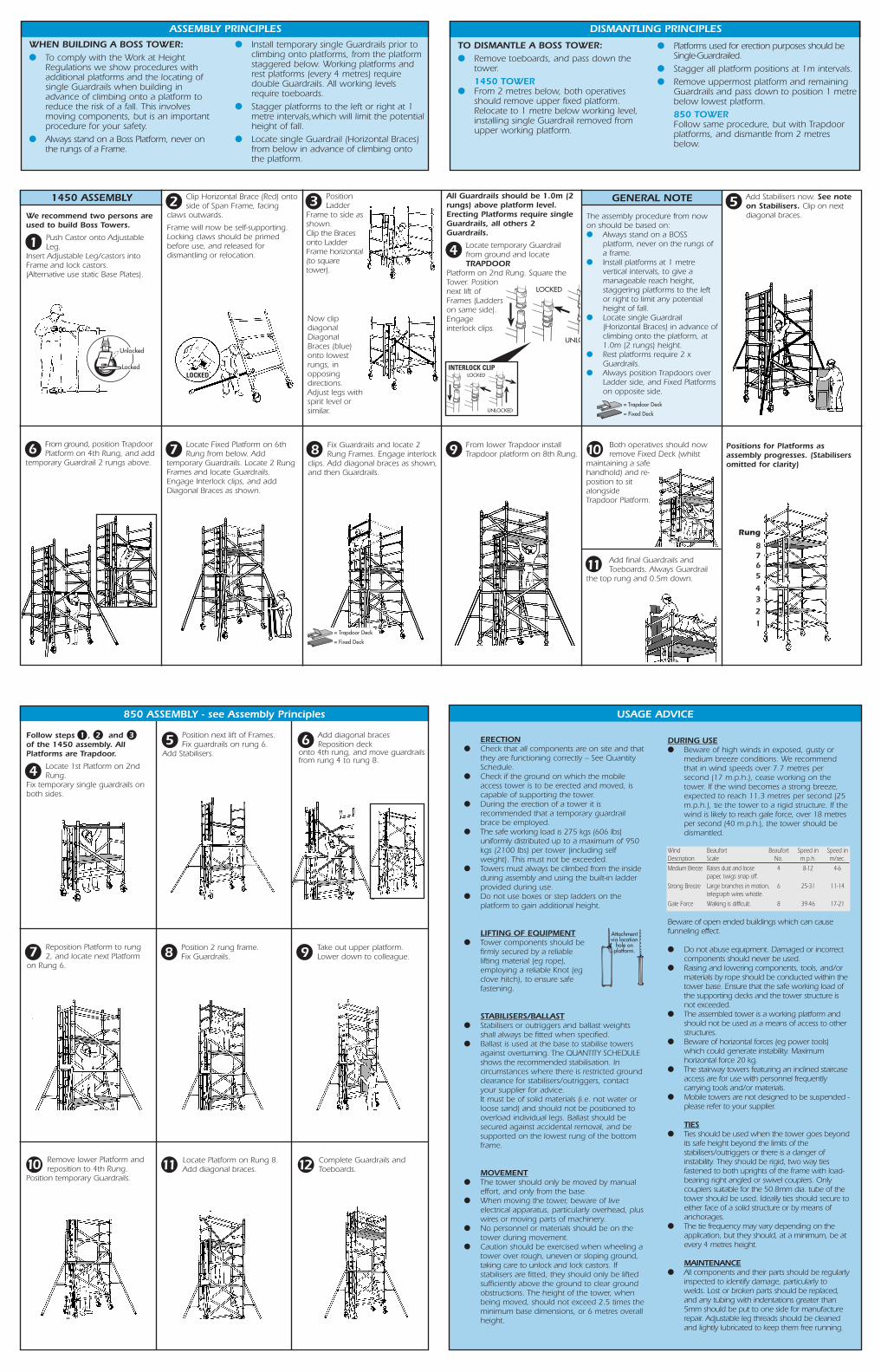
1450 ASSEMBLY
We recommend two persons areused to build Boss Towers.
1 Push Castor onto AdjustableLeg.
Insert Adjustable Leg/castors intoFrame and lock castors.(Alternative use static Base Plates).
2 Clip Horizontal Brace (Red) ontoside of Span Frame, facing
claws outwards.
Frame will now be self-supporting.Locking claws should be primedbefore use, and released fordismantling or relocation.
3 PositionLadder
Frame to side asshown. Clip the Bracesonto LadderFrame horizontal (to squaretower).
All Guardrails should be 1.0m (2rungs) above platform level.Erecting Platforms require singleGuardrails, all others 2Guardrails.
4 Locate temporary Guardrailfrom ground and locateTRAPDOOR
Platform on 2nd Rung. Square theTower. Positionnext lift ofFrames (Ladderson same side).Engage interlock clips.
LOCKED
UNLO
LOCKED
UNLOCKED
INTERLOCK CLIP
5 Add Stabilisers now. See noteon Stabilisers. Clip on nextdiagonal braces.
6 From ground, position TrapdoorPlatform on 4th Rung, and add
temporary Guardrail 2 rungs above.7 Locate Fixed Platform on 6th
Rung from below. Addtemporary Guardrails. Locate 2 RungFrames and locate Guardrails.Engage Interlock clips, and addDiagonal Braces as shown.
8 Fix Guardrails and locate 2Rung Frames. Engage interlock
clips. Add diagonal braces as shown,and then Guardrails.
9 From lower Trapdoor install Trapdoor platform on 8th Rung. 10 Both operatives should now
remove Fixed Deck (whilst maintaining a safehandhold) and re-position to sitalongsideTrapdoor Platform.
11 Add final Guardrails andToeboards. Always Guardrail
the top rung and 0.5m down.
Follow steps 1 , 2 and 3of the 1450 assembly. AllPlatforms are Trapdoor.
4 Locate 1st Platform on 2ndRung.
Fix temporary single guardrails onboth sides.
5 Position next lift of Frames.Fix guardrails on rung 6.
Add Stabilisers.
6 Add diagonal bracesReposition deck
onto 4th rung, and move guardrailsfrom rung 4 to rung 8.
7 Reposition Platform to rung2, and locate next Platform
on Rung 6.9 Take out upper platform.
Lower down to colleague.8 Position 2 rung frame.Fix Guardrails.
10 Remove lower Platform andreposition to 4th Rung.
Position temporary Guardrails.11 Locate Platform on Rung 8.
Add diagonal braces. 12 Complete Guardrails andToeboards.
ERECTION● Check that all components are on site and that
they are functioning correctly – See QuantitySchedule.
● Check if the ground on which the mobileaccess tower is to be erected and moved, iscapable of supporting the tower.
● During the erection of a tower it isrecommended that a temporary guardrailbrace be employed.
● The safe working load is 275 kgs (606 Ibs)uniformly distributed up to a maximum of 950kgs (2100 Ibs) per tower (including selfweight). This must not be exceeded.
● Towers must always be climbed from the insideduring assembly and using the built-in ladderprovided during use.
● Do not use boxes or step ladders on theplatform to gain additional height.
LIFTING OF EQUIPMENT● Tower components should be
firmly secured by a reliablelifting material (eg rope),employing a reliable Knot (egclove hitch), to ensure safefastening.
STABILISERS/BALLAST● Stabilisers or outriggers and ballast weights
shall always be fitted when specified.● Ballast is used at the base to stabilise towers
against overturning. The QUANTITY SCHEDULEshows the recommended stabilisation. Incircumstances where there is restricted groundclearance for stabilisers/outriggers, contactyour supplier for advice.It must be of solid materials (i.e. not water orloose sand) and should not be positioned tooverload individual legs. Ballast should besecured against accidental removal, and besupported on the lowest rung of the bottomframe.
MOVEMENT● The tower should only be moved by manual
effort, and only from the base.● When moving the tower, beware of live
electrical apparatus, particularly overhead, pluswires or moving parts of machinery.
● No personnel or materials should be on thetower during movement.
● Caution should be exercised when wheeling atower over rough, uneven or sloping ground,taking care to unlock and lock castors. Ifstabilisers are fitted, they should only be liftedsufficiently above the ground to clear groundobstructions. The height of the tower, whenbeing moved, should not exceed 2.5 times theminimum base dimensions, or 6 metres overallheight.
Attachmentvia location
hole onplatform.