Input Adjusting Ring Leak Repair Procedure for Meritor …graphicvillage.org/meritor/TP1214.pdf ·...
9
TP-1214 Revised 01-16 Technical Bulletin Input Adjusting Ring Leak Repair Procedure for Meritor MT-14X Series Forward Differential Carriers TP-1214 Revised 01- 16 1 Technical Bulletin Hazard Alert Messages Read and observe all Warning and Caution hazard alert messages in this publication. They provide information that can help prevent serious personal injury, damage to components, or both. WARNING To prevent serious eye injury, always wear safe eye protection when you perform vehicle maintenance or service. Park the vehicle on a level surface. Block the wheels to prevent the vehicle from moving. Support the vehicle with safety stands. Do not work under a vehicle supported only by jacks. Jacks can slip and fall over. Serious personal injury and damage to components can result. Take care when you use Loctite adhesive to avoid serious personal injury. Read the manufacturer’s instructions before using this product. Follow the instructions carefully to prevent irritation to the eyes and skin. If Loctite adhesive material gets into your eyes, follow the manufacturer’s emergency procedures. Have your eyes checked by a physician as soon as possible. Use a brass or synthetic mallet for assembly and disassembly procedures. Do not hit steel parts with a steel hammer. Pieces of a part can break off. Serious personal injury and damage to components can result. Observe all warnings and cautions provided by the press manufacturer to avoid damage to components and serious personal injury. Solvent cleaners can be flammable, poisonous and cause burns. Examples of solvent cleaners are carbon tetrachloride, and emulsion-type and petroleum-base cleaners. Read the manufacturer’s instructions before using a solvent cleaner, then carefully follow the instructions. Also follow the procedures below. Wear safe eye protection. Wear clothing that protects your skin. Work in a well-ventilated area. Do not use gasoline or solvents that contain gasoline. Gasoline can explode. You must use hot solution tanks or alkaline solutions correctly. Read the manufacturer’s instructions before using hot solution tanks and alkaline solutions. Then carefully follow the instructions. Important Notice Meritor 14X series forward differential carriers, manufactured after February 28, 2015, have been redesigned at the input adjusting ring-to-front cover interface. The new interface now incorporates an O-ring at the inboard end of the adjusting ring. Figure 1 and Figure 2. The new and old design adjusting rings and covers are INCOMPATIBLE. Figure 1 Figure 1 4011800a O-RING ADJUSTING RING NEW DESIGN
Transcript of Input Adjusting Ring Leak Repair Procedure for Meritor …graphicvillage.org/meritor/TP1214.pdf ·...
TP-1214Revised 01-16
Technical Bulletin
Input Adjusting Ring Leak Repair Procedure for Meritor MT-14X
Series Forward Differential Carriers
TP-1214Revised 01- 161 Technical BulletinHazard Alert MessagesRead and observe all Warning and Caution hazard alert messages in this publication. They provide information that can help prevent serious personal injury, damage to components, or both.
WARNINGTo prevent serious eye injury, always wear safe eye protection when you perform vehicle maintenance or service.
Park the vehicle on a level surface. Block the wheels to prevent the vehicle from moving. Support the vehicle with safety stands. Do not work under a vehicle supported only by jacks. Jacks can slip and fall over. Serious personal injury and damage to components can result.
Take care when you use Loctite adhesive to avoid serious personal injury. Read the manufacturer’s instructions before using this product. Follow the instructions carefully to prevent irritation to the eyes and skin. If Loctite adhesive material gets into your eyes, follow the manufacturer’s emergency procedures. Have your eyes checked by a physician as soon as possible.
Use a brass or synthetic mallet for assembly and disassembly procedures. Do not hit steel parts with a steel hammer. Pieces of a part can break off. Serious personal injury and damage to components can result.
Observe all warnings and cautions provided by the press manufacturer to avoid damage to components and serious personal injury.
Solvent cleaners can be flammable, poisonous and cause burns. Examples of solvent cleaners are carbon tetrachloride, and emulsion-type and petroleum-base cleaners. Read the manufacturer’s instructions before using a solvent cleaner, then carefully follow the instructions. Also follow the procedures below.
� Wear safe eye protection.
� Wear clothing that protects your skin.
� Work in a well-ventilated area.
� Do not use gasoline or solvents that contain gasoline. Gasoline can explode.
� You must use hot solution tanks or alkaline solutions correctly. Read the manufacturer’s instructions before using hot solution tanks and alkaline solutions. Then carefully follow the instructions.
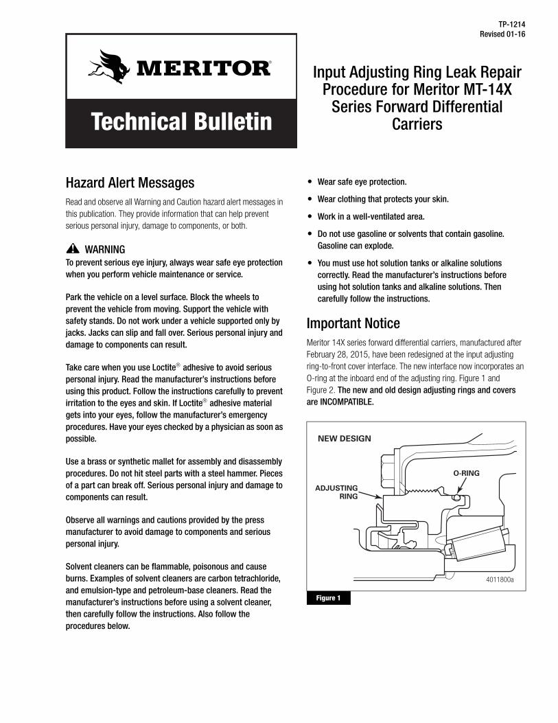
Important NoticeMeritor 14X series forward differential carriers, manufactured after February 28, 2015, have been redesigned at the input adjusting ring-to-front cover interface. The new interface now incorporates an O-ring at the inboard end of the adjusting ring. Figure 1 and Figure 2. The new and old design adjusting rings and covers are INCOMPATIBLE.
Figure 1
Figure 1
4011800a
O-RING
ADJUSTINGRING
NEW DESIGN
TP-1214Revised 01-16 (16579)Page 2 Copyright Meritor, Inc., 2016 Printed in USA
Figure 2
The carrier design version, old or new, must be identified prior to performing repairs. Both the pumped and non-pumped carriers use newly designed covers that have rough part numbers located adjacent to the internal pinion stem. Figure 3 and Figure 4. Both covers shown are the new O-ring design. Covers that do not have one of these two rough part numbers are the old “non-O-ring” design.
There was also an additional internal dimensional change at the O-ring interface during September of 2015. Adjusting rings used in carriers produced from February 28, 2015 to September 23, 2015 are not compatible with later design level covers. Consequently, Meritor has added an adjusting ring to all repair kits that is compatible with all O-ring design covers. Please use the adjusting ring that comes in the repair kit and dispose of the original adjusting ring if the carrier was manufactured from February 28, 2015 to September 23, 2015.
Figure 3
Figure 4
How to Obtain Additional Maintenance, Service and Product InformationRefer to Maintenance Manual MM-0970, MT-14X Series Single-Reduction Forward Differential Carriers on Tandem Axles. To obtain this publication, visit Literature on Demand at meritor.com.
How to Obtain Tools and SuppliesContact Meritor’s commercial vehicle aftermarket at 888-725-9355.
Required Tools
Table A: Tool List
Parts List
The parts you need will vary by the repair required.
Figure 2
Figure 3
4011801a
ADJUSTINGRING
OLD DESIGN
4011802a
ROUGH PARTNUMBER
NEW DESIGN COVER, PUMP VERSION,PART NUMBER 3226T1710
J170 0
Figure 4
Meritor 2728T1 seal installation driver
Meritor 2728T2 sleeve installation driver
Calibrated torque wrench capable of 750-850 lb-ft (1020-1150 N�m)
(Use of a torque multiplier is acceptable)
2-1/4″, 6-point socket
Dial indicator with magnetic base
Pry bar
Standard spanner wrench, size range covering 5.3″ diameter
(Examples: Armstrong Tools 34-310 or JH Williams 474A)
4011803a
ROUGH PARTNUMBER
NEW DESIGN COVER, NON-PUMP VERSION, PART NUMBER 3226S1709
E1695

TP-1214(16579) Revised 01-16Printed in USA Copyright Meritor, Inc., 2016 Page 3
Table B: KIT-2920 Parts for Old Design Cover Repair or Seal Replacement
Table C: KIT-2935 Parts for New Design Cover Repair
Table D: KIT-2936 Parts for Old to New Design Cover Retrofit, Non-Pump
*Use 5X1368 (0.07″ [1.78 mm]) or 5X1414 (0.21″ [5.33 mm]), according to the size of the groove on the carrier face.
Table E: KIT-2937 Parts for Old to New Design Cover Retrofit, Pump
*Use 5X1368 (0.07″ [1.78 mm]) or 5X1414 (0.21″ [5.33 mm]), according to the size of the groove on the carrier face.
Photos Required for Warranty ProcessingIMPORTANT: This repair requires that photographs be supplied to the Meritor OnTrac™ Customer Call Center (866-668-7221) prior to the start of the repair for warranty consideration. Refer to the photographs in the Confirm the Leak section.
Confirm the LeakBefore performing the leak repair procedure, confirm the leak is coming from between the adjusting ring and cover, and not between the seal and yoke. If necessary, clean and inspect the area closely to verify the source of the leak.
Many leaks are misdiagnosed. Some leaks which look like a stain on the front cover surrounding the input yoke area are simply assembly grease. The new seal assembly parts shown in Figure 5 and Figure 6 illustrate the red pre-grease required for the break-in period. A repair is not necessary if there is not an actual “wet” area below the seal and adjusting ring area. Figure 7. Figure 8 shows a true seal or adjusting ring leak which looks wet in appearance.
Part Number Description Quantity
2297L9086 Loctite 577 thread sealant 1
A1 1205X2728 Input seal 1
2214W1271 Input adjusting ring 1
Part Number Description Quantity
2214Q1343 Adjusting Ring 1
5X1477 O-ring 1
A1 1205X2728 Input seal 1
KIT 2826 Input nut and washer 1
2297H8406 Sealant 1
Part Number Description Quantity
2214Q1343 Adjusting Ring 1
3226S1709 Bearing Cage 1
5X1477 O-ring 1
A1 1205X2728 Input Seal 1
KIT 2826 Input Nut and Washer 1
2297A7021 Sealant, Cover to Main Case 1
5X1368 O-ring, IAD to Housing (0.07″ [1.78 mm] for use on earlier carriers, if applicable)*
1
5X1414 O-ring, IAD to Housing (0.21″ [5.33 mm] for use on later carriers, if applicable)*
1
2297H8406 Sealant 1
3221K1025 Baffle 1
1229E1669 Baffle Washers 3
1229D4632 Front Cover Washers 10
Fasteners
MS212035-2 Front Cover Bolts 10
MS208016A-2 Baffle Bolts 3
MS208016A-2 New Lock Plate Bolt 1
Part Number Description Quantity
2214Q1343 Adjusting Ring 1
A 3226T1710 Bearing Cage Assembly, Pump
1
5X1477 O-ring 1
A1 1205X2728 Input Seal 1
KIT 2826 Input Nut and Washer 1
2297A7021 Sealant, Cover to Main Case 1
5X1368 O-ring, IAD to Housing (0.07″ [1.78 mm] for use on earlier carriers, if applicable)*
1
5X1414 O-ring, IAD to Housing (0.21″ [5.33 mm] for use on later carriers, if applicable)*
1
2297H8406 Sealant 1
1229D4632 Front Cover Washers 10
Fasteners
MS212035-2 Front Cover Bolts 10
MS208016A-2 New Lock Plate Bolt 1

TP-1214Revised 01-16 (16579)Page 4 Copyright Meritor, Inc., 2016 Printed in USA
Figure 9 illustrates what to look for when examining seals for a leak. If the seal leaks between the primary seal lips and the yoke, the red pre-grease previously mentioned will wash out. The presence of the red pre-grease between the primary and secondary seal lips indicates that the leak is not coming from the seal lip-to-yoke sleeve interface.
Figure 5
Figure 6
Figure 7
Figure 8
Figure 9
Repair Guidelines
For Leaks Previously Repaired with Kit 2920
If a leak exists, look up the vehicle’s history to determine if kit 2920 has been previously installed. You can use the VIN/chassis # to look it up either in the OEM’s warranty system or the fleet repair facility’s system.
Leak Repair Strategy
� If the red pre-grease is washed out of the area between the primary and secondary lips: Remove and replace the seal ONLY. Refer to the Seal Replacement Procedure in this bulletin.
� If the red pre-grease is not washed out of the area between the primary and secondary seal lips and this a first time adjusting ring leak repair, or if you believe a leak exists but the visual checks are inconclusive: Perform the Leak Repair Procedure in this bulletin.
Figure 5
Figure 6
Figure 7
4011170a
SEAL
RED PRE-GREASEBETWEEN PRIMARY AND
SECONDARY SEAL LIPS
4011171a
RED PRE-GREASEON SEAL SLEEVE
SURFACE
DARK AREA —DOES NOTINDICATE A LEAK
4011172a
DARK AREA —DOES NOTINDICATE A LEAK
Figure 8
Figure 9
4011173a
Visually wetarea indicatesa seal oradjusting ringleak.
4011174a
Pre-grease ispresent betweenthe primary andsecondary seallips.

TP-1214(16579) Revised 01-16Printed in USA Copyright Meritor, Inc., 2016 Page 5
— For old design carriers: Install kit 2920.
— For new design carriers: Install kit 2935.
� If the red pre-grease is not washed out of the area between the primary and secondary seal lips and this is a repeat adjusting ring leak repair: Perform the following.
— For old design carriers: Install a new cover using the Cover Retrofit Procedure in this bulletin. Use KIT 2936 for a non-pumped version or KIT 2937 for a pumped version.
— For new design carriers: Contact the Meritor OnTrac™ Customer Call Center at 866-668-7221 for additional guidance.
Leak Repair Procedure1. Wear safe eye protection. Park the vehicle on a level surface.
Block the wheels to prevent the vehicle from moving.
2. Install a dial indicator and position the tip on the end of the input shaft. Check and record the input shaft end play. Figure 10.
Figure 10
3. Remove the yoke nut and yoke from the input shaft.
4. Clean any debris surrounding the adjusting ring prior to removal to ensure none enters the axle.
5. Remove the bolt from the lock plate and remove the lock plate from the adjusting ring.
6. Remove the adjusting ring from the cover. An air hammer with a blunt tip can be used to facilitate removal of the adjusting ring.
� For old design carriers: Discard the adjusting ring.
� For new design carriers: Keep the adjusting ring for reuse.
7. On new design carriers, remove the O-ring from the adjusting ring and inspect it for damage. Replace it if necessary after the adjusting ring has been cleaned. Also, check the carrier bore for burrs and remove them if necessary.
8. Use brake cleaner to clean the threads of the adjusting ring. Ensure the threads are dry before applying the sealant.
NOTE: For new design carriers, do not allow brake cleaner to come into contact with the O-ring.
NOTE: Suitable tools for cleaning the cover threads are picks, small wire brushes, cleaning solvents such as brake cleaner and compressed air.
9. Place a rag in the carrier cover opening to prevent debris from entering the bearing area during the cleaning process. Use a pick or other suitable tool to clean the old sealant from the axle carrier mating threads in the cover. Do not use air tools to clean the threads. After the old sealant is removed, use brake cleaner to thoroughly clean the cover threads and allow the threads to dry. Figure 11.
Figure 11
10. On old design carriers, ensure the threads of the new adjusting ring and the carrier cover are clean and dry. Apply Loctite 577 thread sealant included in kit 2920 to the entire circumference of the input bearing adjusting ring and the axle carrier cover. Make sure to embed the Loctite 577 thread sealant into the threads thoroughly. Loctite 565 thread sealant can be used as a substitute if necessary.
Figure 10
1002577c
Figure 11
4009826bCARRIERCOVER
Clean old sealantfrom threads.
TP-1214Revised 01-16 (16579)Page 6 Copyright Meritor, Inc., 2016 Printed in USA
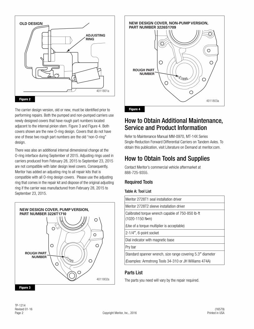
11. On new design carriers, apply a small amount of axle oil to the O-ring and to the O-ring sealing journal inside the carrier cover. Use only the amount of oil necessary to lubricate the O-ring and journal to prevent excess oil from spreading to other parts. Install the O-ring on the adjusting ring. Ensure the threads of the adjusting ring and the carrier cover are clean and dry. Apply thread sealant, part number 2297H8406, included in kit 2935 to the outside diameter of the input bearing adjusting ring. Figure 12.
Figure 12
CAUTIONOn new design carriers, do not allow the O-ring on the adjusting ring to come into contact with the threaded portion of the cover. Damage to the O-ring can result.
NOTE: Use care to avoid overtightening the adjusting ring.
12. Install the adjusting ring into the cover. Tighten the adjusting ring using a target torque of 15-20 lb-ft (20-27 N�m). This range will bottom out the adjusting ring and seat the cup and bearings in the ideal position to obtain correct end play. Do not exceed 20 lb-ft (27 N�m). Rotate the input shaft back and forth to further ensure the bearing is seated. Then, back the adjusting ring out two notches.
NOTE: The yoke does not have to be installed during this step.
13. Check the input shaft end play according to the instructions in Maintenance Manual MM-0970. If necessary, loosen or tighten the adjusting ring one notch to adjust the end play to 0.002-0.008-inch (0.05-0.20 mm).
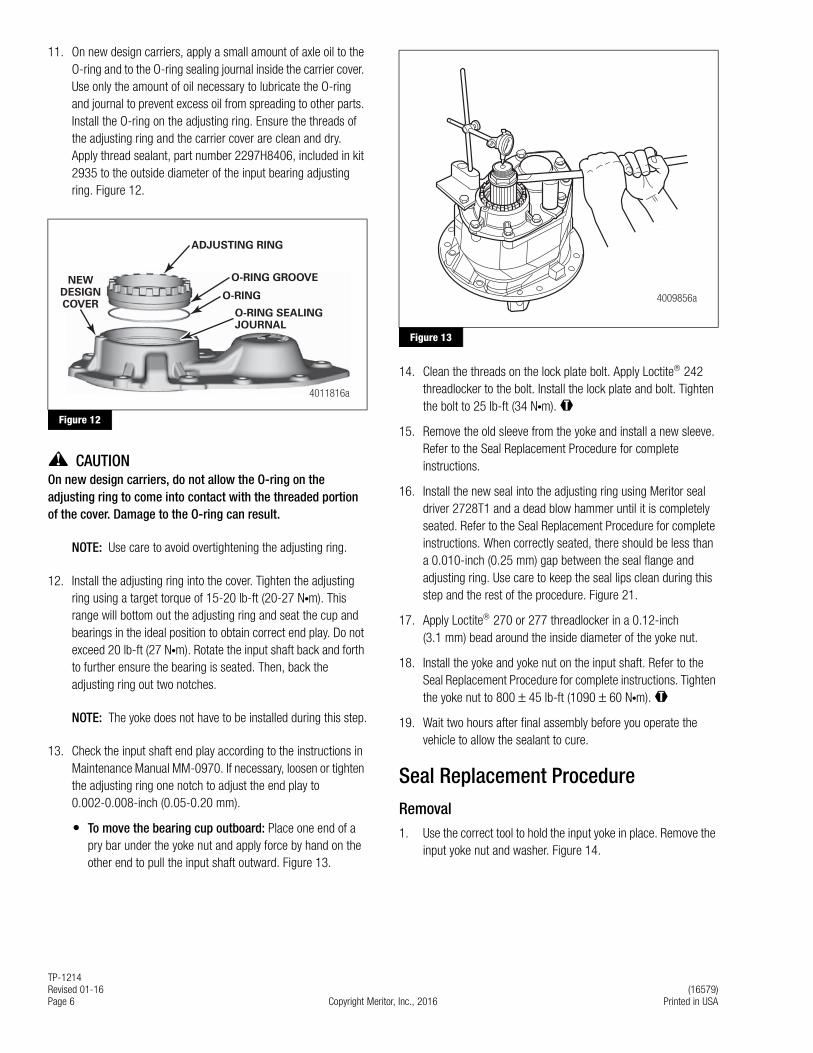
� To move the bearing cup outboard: Place one end of a pry bar under the yoke nut and apply force by hand on the other end to pull the input shaft outward. Figure 13.
Figure 13
14. Clean the threads on the lock plate bolt. Apply Loctite 242 threadlocker to the bolt. Install the lock plate and bolt. Tighten the bolt to 25 lb-ft (34 N�m). @
15. Remove the old sleeve from the yoke and install a new sleeve. Refer to the Seal Replacement Procedure for complete instructions.
16. Install the new seal into the adjusting ring using Meritor seal driver 2728T1 and a dead blow hammer until it is completely seated. Refer to the Seal Replacement Procedure for complete instructions. When correctly seated, there should be less than a 0.010-inch (0.25 mm) gap between the seal flange and adjusting ring. Use care to keep the seal lips clean during this step and the rest of the procedure. Figure 21.
17. Apply Loctite 270 or 277 threadlocker in a 0.12-inch (3.1 mm) bead around the inside diameter of the yoke nut.
18. Install the yoke and yoke nut on the input shaft. Refer to the Seal Replacement Procedure for complete instructions. Tighten the yoke nut to 800 ± 45 lb-ft (1090 ± 60 N�m). @
19. Wait two hours after final assembly before you operate the vehicle to allow the sealant to cure.
Seal Replacement Procedure
Removal
1. Use the correct tool to hold the input yoke in place. Remove the input yoke nut and washer. Figure 14.
Figure 12
4011816a
NEWDESIGNCOVER
ADJUSTING RING
O-RING GROOVE
O-RING
O-RING SEALINGJOURNAL
Figure 13
4009856a

TP-1214(16579) Revised 01-16Printed in USA Copyright Meritor, Inc., 2016 Page 7
Figure 14
2. Use a yoke puller or other suitable tool to remove the yoke from the input shaft. Figure 15.
Figure 15
CAUTIONCarefully remove the oil seal from the adjusting ring. Do not damage the seal bore when you remove the seal. Damage to components can result.
3. Pry under the oil seal flange to remove the oil seal from the adjusting ring. Discard the oil seal. Figure 16.
Figure 16
4. Remove the sleeve from the yoke.
Installation
1. Clean the ground and polished surface of the yoke journal using a clean shop towel and a safe cleaning solvent. Do not use abrasive cleaners, towels or scrubbers to clean the yoke or flange surface. Do not use gasoline.
2. Inspect the yoke seal area for damage that could cause lubricant leaks after you install the seal. Use emery paper or an equivalent product to remove scratches, nicks or burrs only.
3. Install the deflector, if equipped, onto the yoke. You must install the deflector before you install the sleeve onto the yoke. Figure 17.
Figure 17
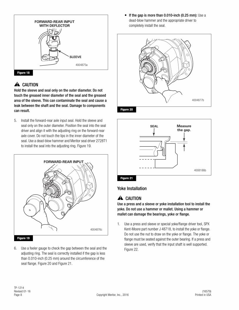
4. Apply a light coat of axle oil to the yoke journal. Position the sleeve into the forward-rear axle input yoke sleeve driver. Do not touch the greased areas of the sleeve. The sleeve must be kept clean prior to assembly into the seal. Use an arbor press and Meritor sleeve driver 2728T2 to install the sleeve into the yoke. Verify that the sleeve is fully-seated in the yoke. Figure 18.
The yoke must be fully pressed into the sleeve driver until the end of the yoke bottoms out in the sleeve driver. This will correctly position the sleeve on the yoke. When correctly seated, the forward-rear input sleeve is positioned 0.030-inch (0.75 mm) from the end of the yoke.
� If you do not have a press: Position the yoke on a five-inch (127 mm) spacer on a workbench. Use a dead-blow hammer and the appropriate driver to install the sleeve into the yoke.
Figure 14
Figure 15
Figure 16
1002725c
1002733c
YOKEPULLER
4008186a
ADJUSTINGRING
SEAL PRYTOOL
Figure 17
4004889a
YOKE
DEFLECTOR,IF EQUIPPED
SLEEVE
DRIVER
TP-1214Revised 01-16 (16579)Page 8 Copyright Meritor, Inc., 2016 Printed in USA
Figure 18
CAUTIONHold the sleeve and seal only on the outer diameter. Do not touch the greased inner diameter of the seal and the greased area of the sleeve. This can contaminate the seal and cause a leak between the shaft and the seal. Damage to components can result.
5. Install the forward-rear axle input seal. Hold the sleeve and seal only on the outer diameter. Position the seal into the seal driver and align it with the adjusting ring on the forward-rear axle cover. Do not touch the lips in the inner diameter of the seal. Use a dead-blow hammer and Meritor seal driver 2728T1 to install the seal into the adjusting ring. Figure 19.
Figure 19
6. Use a feeler gauge to check the gap between the seal and the adjusting ring. The seal is correctly installed if the gap is less than 0.010-inch (0.25 mm) around the circumference of the seal flange. Figure 20 and Figure 21.
� If the gap is more than 0.010-inch (0.25 mm): Use a dead-blow hammer and the appropriate driver to completely install the seal.
Figure 20
Figure 21
Yoke Installation
CAUTIONUse a press and a sleeve or yoke installation tool to install the yoke. Do not use a hammer or mallet. Using a hammer or mallet can damage the bearings, yoke or flange.
1. Use a press and sleeve or special yoke/flange driver tool, SPX Kent-Moore part number J 48718, to install the yoke or flange. Do not use the nut to draw on the yoke or flange. The yoke or flange must be seated against the outer bearing. If a press and sleeve are used, verify that the input shaft is well supported. Figure 22.
Figure 18
Figure 19
SLEEVE
FORWARD-REAR INPUTWITH DEFLECTOR
4004875a
4004876c
FORWARD-REAR INPUT
Figure 20
Figure 21
4004877b
4008186b
SEAL Measurethe gap.
Information contained in this publication was in effect at the time the publication was approved for printing and is subject tochange without notice or liability. Meritor Heavy Vehicle Systems, LLC, reserves the right to revise the information presented orto discontinue the production of parts described at any time.
Copyright 2016 TP-1214Meritor, Inc. Revised 01-16All Rights Reserved Printed in USA (16579)
Meritor Heavy Vehicle Systems, LLC2135 West Maple RoadTroy, MI 48084 USA866-OnTrac1 (668-7221)meritor.com
Figure 22
2. Install a yoke bar or other suitable tool to hold the yoke in place. Figure 23.
Figure 23
3. Apply Loctite 270 or 277 threadlocker in a 0.12-inch (3.1 mm) bead around the inside diameter of the yoke nut. Install the washer and yoke nut onto the input shaft and tighten to 800 ± 45 lb-ft (1090 ± 60 N�m). Figure 23. @
4. Rotate the input shaft one complete turn to seat the bearings.
Cover Retrofit Procedure
NOTE: Follow the correct instructions for “Pump” or “Non-Pump” carriers when referring to procedures in Maintenance Manual MM-0970.
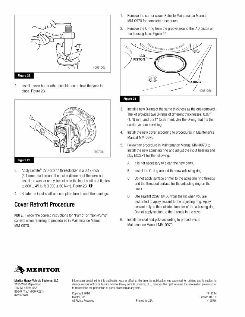
1. Remove the carrier cover. Refer to Maintenance Manual MM-0970 for complete procedures.
2. Remove the O-ring from the groove around the IAD piston on the housing face. Figure 24.
Figure 24
3. Install a new O-ring of the same thickness as the one removed. The kit provides two O-rings of different thicknesses, 0.07″ (1.78 mm) and 0.21″ (5.33 mm). Use the O-ring that fits the carrier you are servicing.
4. Install the new cover according to procedures in Maintenance Manual MM-0970.
5. Follow the procedure in Maintenance Manual MM-0970 to install the new adjusting ring and adjust the input bearing end play EXCEPT for the following.
A. It is not necessary to clean the new parts.
B. Install the O-ring around the new adjusting ring.
C. Do not apply surface primer to the adjusting ring threads and the threaded surface for the adjusting ring on the cover.
D. Use sealant 2297H8406 from the kit when you are instructed to apply sealant to the adjusting ring. Apply sealant only to the outside diameter of the adjusting ring. Do not apply sealant to the threads in the cover.
6. Install the seal and yoke according to procedures in Maintenance Manual MM-0970.
Figure 22
Figure 23
4008100b
1002725c
Figure 24
O-RING
4008192b
IADPISTON