
iNODE for iDOCENT - Michigan State University 3 ECE...The iNODE for iDOCENT is designed to...
62
MICHIGAN STATE UNIVERSITY iNODE for iDOCENT Hardware supplement (iNODE) for Smartphone Application iDOCENT (indoor Digital Orientation Communication and Enabling Navigation Technology 12/01/11 ECE 480 Design Team 3 Team Members: Andrew Dutton, Andrew White, Luke Heide and Zachary Menard Facilitator: Dr. Fathi Salem Project Sponsors: Resource Center for Persons with Disabilities (RCPD) and ArcelorMittal
Transcript of iNODE for iDOCENT - Michigan State University 3 ECE...The iNODE for iDOCENT is designed to...

MICHIGAN STATE UNIVERSITY
iNODE for iDOCENT Hardware supplement (iNODE) for Smartphone Application iDOCENT (indoor Digital Orientation
Communication and Enabling Navigation Technology
12/01/11
ECE 480 Design Team 3 Team Members:
Andrew Dutton, Andrew White, Luke Heide and Zachary Menard
Facilitator: Dr. Fathi Salem
Project Sponsors: Resource Center for Persons with Disabilities (RCPD) and ArcelorMittal

1 | P a g e
Executive Summary
iDOCENT is a phone application created to assist navigation throughout buildings on
Michigan State University’s campus. The phone application includes a universal design with text
to speech technology to help navigate all users, including the visually impaired. iDOCENT uses a
database containing location and transmission power profile for all Wi-Fi access points within
the Engineering Building to compute the location of the smartphone user via a trilateration
algorithm. With the known location of the user, the application applies a routing algorithm to
determine the best path for the selected destination.
The iNODE for iDOCENT is designed to supplement an existing arrangement of access
points to increase system accuracy and expand the application’s scope to buildings without Wi-
Fi networks. The iNODE is more cost efficient than implementing more router access points on
a network, is more portable to allow strategic placement for achieving the best system
accuracy, consumes less power than an average access point or router, and also uses less
airspace. The iNODE’s major components are a Wi-Fi transceiver module, microprocessor, and a
9V battery power supply.
Before the iNODE, the iDOCENT application was limited to buildings with full Wi-Fi
coverage and many access points. Many buildings on MSU’s campus and buildings around the
world do not have the sufficient Wi-Fi coverage or any Wi-Fi coverage to allow for accurate
locating using iDOCENT. Installing iNODEs throughout their buildings would make them
compatible with iDOCENT. The iNODE prototype is currently complete with respect to the
hardware design and PCB layout. Software progress was made on both the wireless module and
smartphone application, but further programming of both is still needed to allow the
application to be used on the Android smartphone platform specifically. If the iDOCENT
application were re-created on the iPhone platform, the current configuration would work.
Team 3 is optimistic that the programming solution for the Android platform is feasible in the
future.
2 | P a g e
Acknowledgement
Michigan State University's ECE 480 Design Team 3 would like to give a special thanks to
the following individuals or companies who helped contribute to the iNODE design solution and
updating of the Android smartphone application and Java server. First we would like to thank
our two sponsors for making this project possible, the Resource Center for Persons with
Disabilities (RCPD) and ArcellorMittal. We would like to specifically give recognition to Mr.
Stephen Blosser of the RCPD for working closely with our team and giving technical suggestions,
support and project guidance throughout the term. We would also like to thank Al Puzzuoli of
the RCPD for his technical contributions and insight throughout the term. We would like to
thank Matt Gottshall from the previous ECE 480 iDOCENT team for providing technical support
with the phone and server application. We would like to thank Microchip’s technical services
and other employees of Microchip including Mark Sawicki and Mark Baynham for their insight
into debugging source code. We would like to thank the ECE shop personnel, including Gregg
Mulder, who milled our PCB. We would like to thank Dr. Fathi Salem for acting as facilitator to
our group, giving us help with project management and performing technical writing reviews
for our group. We would also like to thank Mr. Gregg Motter for guest lecturing in ECE 480 in
which the content of his lectures guided us in critically thinking through our design solution by
using Six Sigma tools. We would like to thank Dr. Michael Shanblatt for his critiques on our
presentations throughout the term and his help with project management. Finally, we would
like to thank Mrs. Roxanne Peacock for placing the orders for all our parts needed throughout
the semester in a timely fashion. Without all the help provided by the aforementioned
individuals the iNODE and iDOCENT interface and functionality would not have been possible.

3 | P a g e
Table of Contents Executive Summary ......................................................................................................................... 1
Acknowledgement .......................................................................................................................... 2
List of Figures .................................................................................................................................. 5
Chapter 1 ......................................................................................................................................... 6
Introduction ................................................................................................................................. 6
Background .................................................................................................................................. 7
Objectives .................................................................................................................................... 9
Software Objectives .............................................................................................................. 10
Hardware Objectives ............................................................................................................. 10
Chapter 2 ....................................................................................................................................... 11
Design for Six Sigma Tools, Budget and Schedule ..................................................................... 11
Fast Diagram ......................................................................................................................... 11
Decision Matrix ..................................................................................................................... 12
Conceptual Design ................................................................................................................ 13
Risk Assessment .................................................................................................................... 15
Budget ................................................................................................................................... 16
Schedule ................................................................................................................................ 19
Chapter 3 ....................................................................................................................................... 19
Key Terms .................................................................................................................................. 19
Design Solution .......................................................................................................................... 22
Server Software Solutions ......................................................................................................... 22
Re-creating and Adding to the Database ............................................................................. 22
Initial Server Problems and Troubleshooting ....................................................................... 24
Phone Software Solutions ......................................................................................................... 24
Initial Phone Application Problems and Troubleshooting .................................................... 25
Hardware Research ................................................................................................................... 26
Hardware Solutions ................................................................................................................... 30
TCP/IP Stack .......................................................................................................................... 31
iNODE Development ................................................................................................................. 32

4 | P a g e
PCB Development ................................................................................................................. 36
Chapter 4 ....................................................................................................................................... 38
Testing ....................................................................................................................................... 38
Software Testing and iNODE Interface Testing ......................................................................... 38
Wi-Fi Connection Test Figures (12, 13, 14, 15) ..................................................................... 39
3G Connection Test Figures (16, 17, 18) ............................................................................... 40
iNODE and iDOCENT Interface .............................................................................................. 41
Chapter 5 ....................................................................................................................................... 42
Project Findings ......................................................................................................................... 42
Future Design Ideas and Suggestions ........................................................................................ 43
Phone Application Enhancement ......................................................................................... 43
Standalone Hardware Navigation Tool ................................................................................. 44
Appendix 1 .................................................................................................................................... 46
Andrew Dutton – Team Manager ............................................................................................. 46
Luke Heide – Document Preparation ........................................................................................ 47
Andrew White – Presentation Preparation .............................................................................. 48
Zachary Menard – Webmaster .................................................................................................. 49
Appendix 2 .................................................................................................................................... 50
References ................................................................................................................................. 50
Appendix 3 .................................................................................................................................... 52
Overall View: GANTT Chart Spread Sheet ................................................................................. 52
GANTT Chart Critical Path ......................................................................................................... 55
3G Code ..................................................................................................................................... 56
PCB Schematic ........................................................................................................................... 57
UDP Code................................................................................................................................... 58
Ping Ad-Hoc ............................................................................................................................... 59
Ad-Hoc Explorer ........................................................................................................................ 60
MAC Address ............................................................................................................................. 61

5 | P a g e
List of Figures Figure 1: FAST Diagram ................................................................................................................. 12
Figure 2: Decision Matrix .............................................................................................................. 12
Figure 3: Conceptual Overall Design ............................................................................................. 14
Figure 4: iNODE and iDOCENT Interface ....................................................................................... 14
Figure 5: Risk Assessment and Legend ......................................................................................... 15
Figure 6: Budget and Development .............................................................................................. 17
Figure 7: iNODE Cost ..................................................................................................................... 18
Figure 8: "Rooms" Table in Database ........................................................................................... 23
Figure 9: "Routers" Table in Database .......................................................................................... 23
Figure 10: Comparing the Microchip TCP/IP Stack Structure to the TCP/IP Reference Model .... 33
Figure 11: PCB Layout ................................................................................................................... 37
Figure 12: Network II Capture ....................................................................................................... 39
Figure 14: iDOCENT Wi-Fi ............................................................................................................. 39
Figure 13: Wi-Fi Connection ......................................................................................................... 39
Figure 15: Server Console Wi-Fi .................................................................................................... 39
Figure 17: Server Console 3G ........................................................................................................ 40
Figure 16: Network Info II 3G ........................................................................................................ 40
Figure 18: iDOCENT 3G ................................................................................................................. 40

6 | P a g e
Chapter 1
Introduction
The Global Position System (GPS) is widely used as a means for navigation assistance in
outdoor applications all around the Earth. Today, GPS is commonly integrated into many mobile
devices including smartphones, which makes navigation assistance applications very common
and portable. Universities around the country have begun taking advantage of this technology
and portability to create applications for navigation assistance throughout campuses for mobile
users. However, GPS is unreliable when used indoors because satellite signal transmissions are
blocked.
The RCPD (Research Center for People with Disabilities) on the campus of Michigan
State University (MSU) and our sponsor contact there, Stephen Blosser, proposed a design
project to overcome this unreliability. The MSU spring ECE 480 team attempted to complete
this design by creating the iDOCENT phone application solution by using Wi-Fi trilateration as a
means for indoor navigation assistance. The iDOCENT application uses a Java Server to access a
database containing a building map, access point location information and access point
transmission power information. With this information, the phone application assigns a factor
based on signal strengths of multiple access points to locate the user. The phone then sends the
known location of the user to the Java Server to apply a routing algorithm to compute the best
path for the selected destination inputted via the smartphone’s user interface.
The main problems with the previous iDOCENT project were the inability of the
application to work in areas where a Wi-Fi network was not available or where there may not
be enough access points for the smartphone application to properly function. Designing a way
to extend the functions of the iDOCENT application to the previously described areas and
creating a more consistently accurate system is very important to the system development.
Without creating a new hardware solution to supplement iDOCENT, the application is limited to
buildings such as the Engineering Building on MSU campus where there are many access points
throughout every hallway. Buildings that desire iDOCENT capabilities would require extending

7 | P a g e
or adding more access points to their network, which comes with a high cost, or create a new
network entirely.
The design of the iNODE is the supplemental hardware solution that will work in
conjunction with the iDOCENT phone application. The purpose is to place the iNODE in a
building where Wi-Fi coverage may not be sufficient in order to increase the accuracy of
iDOCENT, or outfit an entire building without a Wi-Fi network with iNODES to allow iDOCENT
functionality. The potential upsides of the iNODE over a network with access points are cost,
limited security measures needed, portability, and power consumption.
Background
The first step in the creation of the iNODE was to determine if Wi-Fi is still the best radio
frequency (RF) technology option for indoor navigation. Since keeping cost below that of an
access point is critical to actually provide an improvement to the iDOCENT system, research was
initially performed on the other possible RF technologies that both the smartphone software
could utilize and iNODE could transmit. The main RF technologies we considered viable options
were Bluetooth, cellular network or 3G connectivity, Wi-Fi and a possible combination of these
solutions.
Bluetooth is a technology that is common and readily available for use in smartphone
applications, allowing two or more devices to be paired together by a password or pass code.
This was originally considered to be a viable design solution; however, some key drawbacks led
to the dismissal of this RF technology. The range for Bluetooth transmission was the first major
concern addressed. This range is typically only 20 to 30 meters and would call for the
implementation of multiple modules in a given area, which would lead to a rise in cost1.
Another con against Bluetooth is the need for a connection between two devices to allow the
smartphone application code to get relevant transmission power information. This drawback
would not allow multiple users to connect and use the system at the same time. Bluetooth
hardware modules typically do not allow multiple connections simultaneously transmitting and
1 http://www.bluetooth.com/Pages/About-the-Technology.aspx

8 | P a g e
receiving data, and if they do it would not allow the amount of connections potentially needed
with many users using the iDOCENT application.
The cellular network, specifically the 3G signal was the next possible design solution the
team researched. This RF signal is implemented on most new and upcoming phones but it is not
a free service and requires purchasing a data package. Cell phone companies are currently
moving to data packages that have a set limit on bandwidth. Ultimately, if iDOCENT were used
often by the visually impaired, high data usage rates would occur as it loads maps in real time
as the user moves. The team wants iDOCENT to be able to be used often with no extra cost to
the user. Other drawbacks that we have found in researching 3G signal is that signal strength in
certain areas is not always reliable in buildings around campuses or in basements of buildings.
The basement in the Engineering Building at Michigan State University is a good example of
this, where Wi-Fi is not available.
Wi-Fi is the RF signal that was considered to be the best option before the research and
after was decided as the solution for our iNODE. Virtually all smartphones today are Wi-Fi
capable, and users often prefer it to using their 3G data plans because of faster data transfer
rates in certain areas and the data limits discussed previously. Wi-Fi networks are also very
common and available in buildings, especially on college campuses, to allow the base for indoor
navigation. A strong advantage to using Wi-Fi is that it incorporates signal strength packages
into its transmission to other Wi-Fi compatible devices and is easily accessed with smartphone
application code. An area of concern, however, with Wi-Fi is a possibility of causing a disruption
in the transmission bandwidth and slowing down upload and download speeds for other
devices on that network. The possibility of combining Wi-Fi with another technology was
quickly dismissed, as cost of their respective transceivers would make the iNODE more
expensive than access points with little advantages gained. A decision matrix was created based
on these criteria and is located in Chapter 2.
In order to create the iNODE as a Wi-Fi communicating device one has to understand
the structure of the Wi-Fi band of frequencies. Wi-Fi is a brand name for devices that use the
IEEE 802.11 standards for communication. Wi-Fi devices can communicate with the 802.11

9 | P a g e
standards at 2.4GHz, 3.6GHz, and 5GHz frequency channel as long as they are Wi-Fi Certified by
the Wi-Fi Alliance. Since smart phones today use the licensed 2.4 GHz Wi-Fi, the iNODE will
need to be able to communicate on the licensed 2.4GHz band as well. Many companies on the
market produce Wi-Fi certified transceiver modules. The certification of the module comes
from the set of finely defined rules for the amount of data that is allowed to be transferred on
this band per device. If a device transfers data accordingly to the IEEE 802.11 standards, then it
will receive certification.
After researching many transceiver modules, we decided to go with the Microchip
MRF24WB0MA Wi-Fi module. Microchip’s Wi-Fi module stands at the top of its class offering
three operating modes; transmit (drawing 174mA), receive (84mA), and hibernate (250uA),
allowing this device to consume less power than most other transceiver modules. The Wi-Fi
module is also compatible with multiple Microchip Microcontrollers allowing for 8-bit, 16-bit, or
32-bit operation. Microchip has a user friendly application development platform (MPLAB), and
Microcontrollers operate on common C programming commands allowing for easy
programming. In order to operate this module on the licensed band, data transfer must follow a
specific family of network protocols that are supported by the IEEE 802.11 standards. TCPIP is
the common family of network standards for internet communication. Microchip has
developed pre-compiled C code for the TCP/IP stack that can be easily downloaded to the
microcontroller through the MPLAB development system. This allows for users to simply build
their desired internet application, and send this information through the TCP/IP stack in order
to guarantee communication on the certified Wi-Fi band.
Objectives
The final goals of the project were to create a successful interface with the iNODE
module and iDOCENT smartphone application without the need of an external Wi-Fi network,
and to design a stand-alone hardware unit (iNODE) capable of programming and powering the
Wi-Fi Microchip transceiver. To complete the final goal of creating a successful interface
between the iDOCENT smartphone application and the iNODE hardware device, many steps
and objectives were set throughout the semester involving the iDOCENT application, the Java

10 | P a g e
Server and the iNODE module. For easier communication and dividing workloads, the project
was split into software side of the project, including everything involved with iDOCENT and the
Java Server, and the hardware side of the project, including everything involved with the iNODE
module.
Software Objectives
The software side of the project was split between the actual iDOCENT smartphone
application and the Java Server. The first objective of the semester on the software side was to
replicate the server that the previous ECE 480 team set up so that the iDOCENT application
would run properly on an Android device. From there, the code of the phone had to be
modified to allow for 3G connections to the server. Previously, the phone application could only
connect to the Java Server over a Wi-Fi connection, and since our goal is to allow for navigation
in areas without a Wi-Fi network, an addition of the 3G option was necessary to obtain
database information. The third objective was to update the database with the Media Access
Control (MAC) address of the Wi-Fi chip within the iNODE, preferred location of the iNODE
device within the engineering building and the transmission power of the Wi-Fi chip. An
addition objective was to try to expand the possible coverage of the iDOCENT application to the
Michigan State University Union, utilizing our iNODE device and allowing for a demo for design
day.
Hardware Objectives
The main goal of the iNODE hardware is to create a device that will transmit in a manner
that will allow the iDOCENT cell phone application to recognize the device, and use this device
in its location algorithm to successfully navigate one through a building. To accomplish this
goal, many objectives were set throughout the term.
The iNODE will be the hardware portion of the design solution and will be competing
with Wi-Fi access points such as routers, as they are currently the other solution to outfitting
buildings for iDOCENT capabilities. Since access points are the direct competitor, the main
objectives are to make certain the iNODE has an advantage over them. The first objective of the
iNODE was to choose and interface a proper microcontroller and microprocessor to maintain

11 | P a g e
the protocol layering for the certified IEEE Wifi 802.11 Wifi band for the chosen Wi-Fi module.
The next objective was that it should be portable, which will allow for precision placement of
the device to achieve maximum accuracy. Finally, the iNODE cost for manufacturing must stay
lower than that of an average access point.
Chapter 2
Design for Six Sigma Tools, Budget and Schedule
Fast Diagram
The ultimate goal of the project is to interface the iNODE hardware with the iDOCENT
application. The FAST diagram highlights how this goal is accomplished. The diagram is read
from left to right, with the question "How?" being asked for each successive step to the right.
The diagram is read from right to left with the question "Why?" being asked for each successive
step to the left. To successfully interface the iNODE with iDOCENT, the iNODE must be made
discoverable by the smartphone and the smartphone must be able to download the iNODE Wi-
Fi information. To make the iNODE discoverable, the device must transmit an access point (AP)
signal. To transmit the AP signal, the Wi-Fi module within the iNODE must be powered and
properly programmed; to properly download the iNODE Wi-Fi information, the database must
be accessed; to access the database there must be communication with the server and the
information must be stored. These steps are illustrated in Figure 1 on the next page.

12 | P a g e
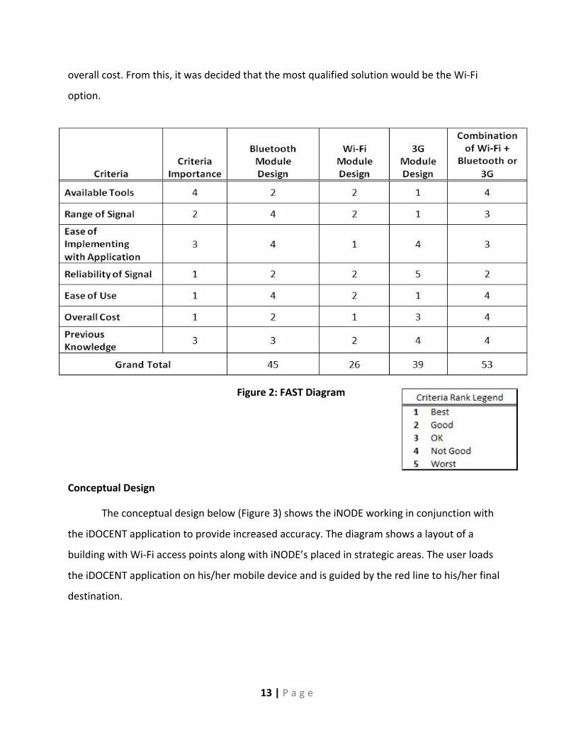
Decision Matrix
After researching different RF technologies that could be used for our design, a decision
matrix was created to show the pros and cons of each technology. This matrix is based off of a 1
through 5 ranking system with 1 being the best and 5 being the worst, and corresponds to
criteria that are required for our design. Some criteria that were seen as important in ranking
each technology were available tools, range of signal, ease of implementation, previous
knowledge and the three most critical: reliability of signal, ease of use, and overall cost. The
appropriate data was inputted into the matrix and totals were tallied up, which produced one
viable option.
After reviewing the data from the matrix, Wi-Fi is shown to have good qualities in each
criterion and was very strong in ease of implementation with the iDOCENT application and
Figure 1: FAST Diagram
13 | P a g e
overall cost. From this, it was decided that the most qualified solution would be the Wi-Fi
option.
Conceptual Design
The conceptual design below (Figure 3) shows the iNODE working in conjunction with
the iDOCENT application to provide increased accuracy. The diagram shows a layout of a
building with Wi-Fi access points along with iNODE’s placed in strategic areas. The user loads
the iDOCENT application on his/her mobile device and is guided by the red line to his/her final
destination.
Figure 2: FAST Diagram

14 | P a g e
The diagram below (Figure 4) shows the iNODE’s internal structure and its ability to
work alongside the iDOCENT application. The Wi-Fi module will include a power unit, which will
be a 9-volt battery that is regulated down to 3.3 and 5 volts, a Wi-Fi module with built in PCB
antenna, and a PIC24F microprocessor to control the module. This module will communicate
with the Smartphone similar to how an access point would and transmit its MAC address and
signal strength, which is processed by the iDOCENT application to locate the user and generate
a path to his/her destination.
Figure 3: Conceptual Overall Design
Figure 4: iNODE and iDOCENT Interface

15 | P a g e
Risk Assessment
The risks of the iDOCENT and iNODE project are defined by the table below (Figure 5) ,
which shows crucial areas in which the design could be flawed. This table presents the issue
that designing the Wi-Fi module, programming the microcontroller, testing, and designing a
unique PCB can all affect the projects progression towards the final deadline and its ultimate
failure or success.
Figure 5: Risk Assessment and Legend

16 | P a g e
Budget
The iNODE should be a low cost solution that is cheaper to produce than a Wi-Fi router.
If the router can be made cheaper, then there would be no market for this device that is
specifically used to supplement the iDOCENT application for indoor navigation. The
development and prototyping costs of the iNODE and iDOCENT application can be seen in figure
6 on the next page. Cost of the prototype was kept to a minimum by using MSU facilities for the
printed circuit board fabrication, the ECE shop for circuit components, and cell phone
application development was done at no cost. The bulk of the cost was in the Microchip
development board that was purchased to optimize and test the performance of the hardware.
The financial analysis shows that we still have $205.81 left in the budget for prototyping and
development costs.

17 | P a g e
Figure 6: Budget and Development

18 | P a g e
Once the development was complete enough to produce a final design product, we
were able to compose the projected cost of this device once they are produced in a higher
volume. Figure 7 below shows the circuit components needed to produce the iNODE and what
the projected cost would be at volume purchasing. We were able to meet the goal of the
keeping the iNODE cheaper than a router at a projected cost of $26.83. Because the iNODE is a
Wi-Fi communicating device, we need a licensed Wi-Fi transceiver, making this the core
component of our product and the bulk of the cost. The Microchip MRF24WB0MA transceiver
module is competitively priced among the other transceiver modules on the market today and
stood at the top of its class in terms of power consumption and transmit ranges.
Figure 7: iNODE Cost The cost of the PCB is neglected,
but size estimates of a final PCB
are (1.5 in x 3 in)

19 | P a g e
Schedule
The project management plan and Gantt chart describe the personnel and their tasks,
the resources to be used and the project schedule. The schedule contains a breakdown of
related sub-tasks with their time requirement and the respective time frame for completion.
Technical tasks, along with the non-technical deliverables, are all clear and well-defined within
the plan. This project objective was re-defined multiple times throughout the semester. A final
project objective was reached after 6 weeks of research and progress of older designs. From
the two Gaant charts below you can see how the project changed throughout the course,
ultimately leading to the critical path for completion. The critical path was the research, design,
ordering and testing of the pseudo-router (renamed the iNODE), and the necessary updates to
the cell phone application. These two main objectives were to be finished at the same time to
allow for proper testing of the integrated solution. The GANTT chart spreadsheet and GANTT
chart critical path can be found in the beginning section of Appendix 3.
Chapter 3
Key Terms
IDE - Integrated Development Environment - A program designed for programmers making
programming and executing applications easier2
(W)AP - (Wireless) Access Point - A device that allows another wireless device to connect
wirelessly to a network3
MAC address - Media Access Control Address - The physical address of a network device4
Wi-Fi - Wireless Fidelity - Protocol used for wireless local area networks5
IEEE - Institute of Electrical and Electronics Engineers6
IEEE 802.11 - Set of standards for providing Wireless Local Area Networks7
2 http://en.wikipedia.org/wiki/Integrated_development_environment 3 http://en.wikipedia.org/wiki/Wireless_access_point 4 http://en.wikipedia.org/wiki/Mac_address 5 http://en.wikipedia.org/wiki/Wifi 6 http://www.ieee.org/index.html

20 | P a g e
MPLAB IDE - MPLAB Integrated Development Environment - Development platform for
Microchip Microprocessors, which allows for written code to be debugged and downloaded to
the PIC Microprocessor
TCPIP or TCP/IP - Transmission Control Protocol/Internet Protocol8
PCB - Printed Circuit Board
PIM - Plug-in Module - PCB on which the PIC24Fj128GA101 is mounted
TCPIP stack - Refers to the stack of protocol's to follow the TCPIP process as per 802.11
standards9
RF - Radio Frequency - Signals with frequency range of about 3 kHz to 300 GHz10
SDK or JDK - Software Development Kit or Java Development Kit - Set of tools that assist
development of an application11
SQL - Structure Query Language - Programming language designed to update database
management systems12
3G - 3rd generation mobile telecommunications - Standards for mobile phones and mobile
telecommunication13
OS - Operating System - Set of programs that manage a computer's hardware resources14
OSI model - Open Systems Interconnection model - " It is a prescription of characterizing and
standardizing the functions of a communications system in terms of abstraction layers"15
DSSS Modulation - Direct-sequence spread spectrum modulation - Modulation technique
where the transmission signal takes up more bandwidth than the information being
modulated16
7 http://en.wikipedia.org/wiki/IEEE_802.11 8 http://en.wikipedia.org/wiki/Internet_protocol_suite 9 http://en.wikipedia.org/wiki/Internet_protocol_suite 10 http://en.wikipedia.org/wiki/Radio_frequency 11 http://en.wikipedia.org/wiki/SDK 12 http://en.wikipedia.org/wiki/SQL 13 http://en.wikipedia.org/wiki/3G 14 http://en.wikipedia.org/wiki/Operating_system 15 http://en.wikipedia.org/wiki/OSI_model 16 http://en.wikipedia.org/wiki/Direct-sequence_spread_spectrum

21 | P a g e
OFDM Modulation - Orthogonal frequency-division multiplexing - A frequency-division
multiplexing scheme used as a digital multi-carrier modulation method17
FCC - Federal Communications Commission - Regulates interstate and international
communications dealing with radio, television, wire, satellite and cable in the United States18
BSSID - Basic service set identification - The BSSID is the MAC address of a WAP19
MAC Layer – Medium Access Control Layer- The physical layer for transport
UDP – User Datagram Protocol - Protocol for computer applications to send datagrams to
other hosts on an IP without prior communications20
RAM – Random Access Memory
17 http://en.wikipedia.org/wiki/Orthogonal_frequency-division_multiplexing 18 http://www.fcc.gov/what-we-do 19 http://en.wikipedia.org/wiki/BSSID#Basic_service_set_identification_.28BSSID.29 20 http://en.wikipedia.org/wiki/User_Datagram_Protocol

22 | P a g e
Design Solution
Server Software Solutions
The previous ECE 480 iDOCENT team produced an application that was ready for use on
Android smartphones, but it required a connection to a server with an accessible database
containing all access point locations and MAC addresses, the routing algorithm written in Java
code, and the building map information. The first step in the design solution was to replicate
this server and database, and add to it relevant iNODE information to it.
The setup that was used for this term's server was a 64-bit Windows machine running
MYSQL21 open source database program and Eclipse IDE 22for running the Java server code
version 1.6_24. The server stores all the relevant information in an SQL database in MYSQL and
is interfaced with the phone through the server code as follows: the phone makes a connection
to the server's router, the router routes the request to a specified port on the server computer
and the server code listens for requests on the specified port. Once the server code picks up the
request, it sends the information within the database to the phone application.
Re-creating and Adding to the Database
To re-create the database, SQL scripting language was used within MYSQL to recreate
two, six column tables; "rooms" and "routers". The "rooms" table columns consisted of the
room number for allowing the code to access the entry when a destination is selected by the
user, the type of room it is, an X location coordinate, Y location coordinate, Z location
coordinate, and a column listing all neighbors of the room to be utilized by the navigation
routing algorithm as shown in figure 8 below. The "routers" table columns consisted of an
unique ID to allow the code to access the entry, the specific AP MAC address, an X location
coordinate, Y location coordinate, Z location coordinate, and SSID column as shown in figure 9
below. The server code was changed appropriately to reflect the changes in the database
name, password, and server IP address. The tables were re-populated via SQL scripting with all
21 http://www.mysql.com/ 22 http://www.eclipse.org/

23 | P a g e
access points and rooms that were utilized last term, with the addition of an added iNODE
access point that would be located outside the ECE 480 lab in the engineering building. This
would allow easy testing of the unit, as the engineering building access point outside the lab
could be deleted when the iNODE is being tested. Testing procedures are explained in more
detail in Chapter 4. Learning SQL scripting language was a small problem when first replicating
the server, but tutorials at w3schools.com 23and communication with the previous iDOCENT
team helped overcome this issue.
23 http://www.w3schools.com/sql/default.asp
Figure 8: "Rooms" Table in Database
Figure 9: "Routers" Table in Database

24 | P a g e
Initial Server Problems and Troubleshooting
There were three main problems that proved to be the most time consuming to solve
when setting up the server and database. They were: correctly importing the Java server code
into the Elipse IDE, modifying the server code to properly run on the new server and setting up
security settings on the server router and computer. Importing the Java server code required an
understanding of the standard Java uses for database connectivity, JDBC (Java Database
Connectivity). The JDBC library must be imported into the code before the project can be
compiled to run. Also, the server code had to be updated to be in line with the port chosen
during the MYSQL setup and the IP address of the server computer. Finally, once the code was
compiled and running properly, the security settings of the server router had to be modified to
allow connections from clients requesting specific port access. The details and a tutorial to
solving all of these solutions can be found in Luke Heide's Application Note, "Android Operating
System Application Development with MYSQL Server Connectivity,"24 located on Team 3's
webpage.
Phone Software Solutions
With the server being functional, testing and debugging of the actual iDOCENT
smartphone application could commence. However, an Android development environment had
to be setup and the application code had to be imported. Next, the code had to be modified to
properly interface with the new server and to allow 3G connectivity to the server. The previous
team's code required a connection to a Wi-Fi network in order to gain access to the server for
the downloading of data. As mentioned in the objectives, this feature takes away from the
universality of the phone application, as it would not be functional in buildings with only
iNODES or the lack of Wi-Fi network connectivity. Finally, an attempt to outfit the Union for a
demo on Design Day was to be made.
The development environment utilized by Team 3 was the Eclipse IDE with the JDK7
installed, the Android SDK Starter Package for eclipse installed and the ADT Plug-in for Eclipse
24 http://www.egr.msu.edu/classes/ece480/capstone/fall11/group03/doc.html

25 | P a g e
installed, which allows for the building of Android smartphone applications. The iDOCENT
application was built using the Android platform 2.1. The phone application code was imported
into the same workspace and IDE as the Java server code.
Initial Phone Application Problems and Troubleshooting
Modifying the code to interface properly with the new server, adding 3G connectivity to
the application, and setting up the union for a location demo were the three main problems on
the phone application side. There were three code files within the iDOCENT application that
required updating to properly interface the new server and the application. Within these three
code files the following information had to be changed: the portion of code containing the port
of the server computer, the IP address of the server computer, the database name, and
database password. For more details and a tutorial for setting up the Android development and
changing the smartphone application code to properly interface with a new server, see Luke
Heide's Application Note25. The team received much help from the previous iDOCENT team
with this portion of the code.
To solve the problem of properly adding 3G connectivity, an understanding of the
Android Wi-Fi library was needed, as the previous team required a Wi-Fi connection via code
commands from this library. A good explanation of the Wi-Fi library and how it was used was
supplied in Matthew Gottshall's application note, "How to Program an Android Application to
Access and Manage the Wi-Fi Capabilities of a Smartphone,"26 from the previous iDOCENT
team's website. This application note was utilized when making updates to the code. When
using the standard Android connection commands to access the internet, the phone always
tries to connect via Wi-Fi first, and then will resort to 3G connectivity. The previous team did
use standard Android connection commands when writing the code to connect to the server,
but provided logic to make sure that a Wi-Fi connection was used and a 3G connections was
disallowed. This problem was solved by finding the connection portion of the code and
25 http://www.egr.msu.edu/classes/ece480/capstone/fall11/group03/doc.html 26 http://www.egr.msu.edu/classes/ece480/capstone/spring11/group02/documents/matt_appnote.pdf

26 | P a g e
rewriting it without the extra logic. Appendix III, "3G Code", contains the code that was
modified to allow 3G connections.
The initial plan to map out the Union and update the database to include all routers’
transmission powers and locations inside the building proved to be intractable after examining
the iDOCENT code and its trilateration algorithm. Location is determined by normalizing the
user to a location defined as the center of each hallway of the Engineering Building. This
scheme works fairly well when used in the Engineering Building because of its narrow corridors
and numerous access points lining the hallways, however, when translated to a more open
space, some conflicts occur.
In a large space, the paths cannot be accurately drawn because of the many locations
the user could be in. Multiple paths could potentially be drawn, but there would be no way of
accurately determining which path the user is on, unless an iNODE module is placed centrally in
the large space, or many iNODEs are distributed within the space. With a large alteration to the
method of trilateration in the code to work in settings that are not narrow hallways, the iNODE
could have a lot of value in this situation. We are confident that with this alteration, the iNODE
could outfit any building no matter how large the space to provide accurate location detection.
Hardware Research
The goal of the iNODE is to meet the design objectives to satisfy the customer. In order
to create a device that will properly interface with the iDOCENT hardware the team needed to
gain an understanding of how the iDOCENT hardware surveys the Wi-Fi network for the access
points. Because this is done on the Wi-Fi band, the iNODE needed to be a Wi-Fi device that
would mimic a router, but it did not need to specifically be a router. In order to do this, a device
was required that contains a license to communicate on the Wi-Fi band as well as be able to
support the proper protocol layering and signal modulation to communicate over Wi-Fi. The
implications of these goals meant the iNODE is an attempt to build a wireless router at a
cheaper cost than what is produced at a large scale.

27 | P a g e
To produce a device that has the capabilities to communicate on the Wi-Fi band, the
team needed to look at the Wi-Fi standards for communication. Wi-Fi is a brand name for
devices that use the IEEE 802.11 standards for communication and Wi-Fi devices can
communicate with the 802.11 standards at 2.4GHz, 3.6GHz, and 5GHz frequency channel as
long as they are Wi-Fi Certified by the Wi-Fi Alliance. The typical Wi-Fi routers today use the
IEEE 802.11b/g standards as the Medium Access Control transport layer of the OSI model for
internet communication. The b and g refers to the data rate allowed to stream information
across the transmission medium, which is air for wireless communication at 2.4GHz. B supports
5.5 and 11 Mbits/s for a transceiver data rate, and g supports 6, 9, 12, 18, 24, 36, 48, 54
Mbits/s. The different standards also refer to the form of modulation being used in the
transceiver module, b supports DSSS modulation, and g supports DSSS and OFDM modulation.
These standards are necessary to be understood, because in order to use a device for
communication on the Wi-Fi band, the transceiver modules must not exceed these limitations.
A more recent version of the IEEE standards has come out for Wi-Fi communication, being
802.11n. 802.11n supports 7.2, 14.4, 21.7, 28.9, 43.3, 57.8, 65, 72.2 Mbits/s and only supports
the OFDM modulation. The data rates and the modulation allow for better indoor range
connectivity to the device. Because the iDOCENT cell phone application uses the internal Wi-Fi
transceiver on the cell phone as a means to find reference objects to locate the person, we
need to make sure that our transceiver can effectively communicate in the proper manner to
the cell phone. The cell phone application is set up to work with multiple routers operating at
today's common IEEE 802.11x standards. Therefore we need a transceiver that supports the
strongest data rate profile with the indoor range transmission profile at the cheapest cost.
The FCC, an American government run commission, regulates the available frequency
spectrum for use. Because of this, there is not only a need for a transceiver device to meet the
above IEEE 802.11x Wi-Fi standards, but there is also a need for the device to be certified for
communication by the FCC on the Wi-Fi band across America. Therefore, constructing a 2.4GHz
radio transceiver could potentially be cost effective, but the FCC would not allow this device to
be used for IEEE 802.11 Wi-Fi communication. In order to earn this necessary certification, the
creator of the device needs to perform numerous tests on the transceiver module displaying

28 | P a g e
that it does not exceed the bandwidth, data rate, or modulation techniques to be able to
communicate on the Wi-Fi band. This outlines the importance to incorporate a device that is
currently licensed by the FCC for IEEE 802.11 Wi-Fi communication.
There are numerous companies who produce Wi-Fi transceiver modules that perform at
different operating levels. To effectively choose the most appropriate Wi-Fi transceiver for the
iNODE application, further research was performed to understand the interface necessary
between the iNODE and iDOCENT application. As stated before, the iDOCENT application
supports most of today's routers that are operating at IEEE 802.11 b,g, and n. Deciding how the
team could limit cost on this module and still interface with the application came from the
knowledge of the structure of the Wi-Fi communication networking interface itself. For
communication between the wireless interfaces of an AP to the wireless interface of a cell
phone, certain brands of transceiver modules support different networking protocols. The
structure of the internet's protocol layering between two Wi-Fi devices is outlined in the TCP/IP
networking structure for internet communication. TCP/IP is a set of communication protocols
used for the internet and other similar devices. In order to define the type of transceiver
module we wanted to incorporate into the design of the iNODE, we needed to understand
which protocols would be supported to interface to the iDOCENT cell phone application. Most
companies who produce the Wi-Fi certified transceiver modules also suggest the
microprocessor needed to drive the transceiver module. They also typically have a pre-written
TCP/IP stack that can be loaded on to the microprocessor to allow for proper communication
on the Wi-Fi network. This is another area where some device couples stood above others.
In order to interface the iNODE with the iDOCENT application the team wanted our
module to be distinguishable as an independent device, able to transmit empty packets into the
transmission medium for the cell phone to pick up and use for trilateration. In order to do this,
a TCP/IP stack that could support being configured as an access point, or have the ability to
create its own Ad-Hoc network was needed. The assumption was that once this device is
configured to act as a legitimate transmission device with a BSSID, the cell phone application
could then recognize the message sent. To effectively leave space open on the microprocessor

29 | P a g e
for future modifications to the iNODE, the most light-weight TCP/IP protocol stack that could
support operation as an access point or as a distinguishable network was the best option. This
narrowed down the options for the transceiver module.
In the IEEE 802.11 standards for Wi-Fi communication, all devices deemed
conversational must effectively probe the network. Therefore, for any device to communicate
data back and forth on the Wi-Fi network, a network probe must first be sent. The probe occurs
in the MAC layer of the TCP/IP model. Devices will effectively transmit a probe packet that
communicates to all Wi-Fi users in range that a device is present. The probe is not limited to
physical devices transmitting data such as a router, but is done by all devices capable of
communicating with the proper protocols and certification. A device cannot be configured as an
access point if it does not perform the probe in its TCP/IP MAC layer model for IEEE 802.11x
communication. This means that certified Wi-Fi transceiver modules with their respective
TCP/IP downloadable stack do not all have support for probing, yet made the claim that they
can be configured as an access point. In order for the phone to receive information from the
iNODE, the iNODE will effectively need to respond to the phones probe request with a probe
response. In this probe request and probe response, both the requested and responded probe
packet will contain the physical device’s MAC address. From this probe response, the cell phone
will send an authentication packet asking if the iNODE is a network. In order for the iNODE to
respond that it is its own network as either an Ad-Hoc or infrastructure access point, the iNODE
will need to send an authentication response packet to respond to the phones response. Then
the cell phone will send a request to join the Ad-Hoc or infrastructure network allowing the two
devices to connect to each other. This is simply to establish a physical end to end connection
between the two devices.
From the research performed to fully understand the communication networking
needed to properly interface the iNODE and iDOCENT application, there were only a few
companies who supported these necessary data rates, protocols, and set up configurations to
act as a network. Microchip offers the solutions that cover all the items mentioned at a

30 | P a g e
reasonable cost. Microchip also offers 24/7 technical support and a free software development
program to use their products to develop independent applications.
Hardware Solutions
The Wi-Fi transceiver is the backbone to the iNODE. To develop the best solution, we
need to use the best products. The MRF24WB0MA Wi-Fi transceiver Module produced by
Microchip offered many features that made it the best solution for our project. This Wi-Fi
transciever meets the 802.11 standards which the IEEE requires for a compliant RF transceiver,
as well as licensed by the FCC for communication on the Wi-Fi band. Since the iNODE will be
interacting with cellular devices, it will need to be able to transmit its MAC address and signal
strength for the cellular device to interface and pass along to the iDOCENT application. This Wi-
Fi module features its own unique MAC address that can be configured and also includes an
integrate PCB antenna that outputs 10dBm of power with a range of 400 meters. This antenna
will allow for this unique MAC address and appropriate signal strength to be transmitted along
to the cellular device, which then passes it along to the iDOCENT application. The Wi-Fi module
also allows for varied power consumption by providing four different states which are defined
by receiving mode, transmit mode, sleep, or hibernate and draws 85mA, 154mA, 250uA, or
0.1uA respectively. Some features that allow it to be compatible with other devices are the
ability for the Wi-Fi module to work along with Microchip’s PIC microcontrollers, including the
PIC24F family. The Wi-Fi module also comes in a compatible PCB daughterboard, which allows
for ease of connection between other interfaces, including the Microchip’s Explorer 16
Development board, which will allow for development, debugging and programming.
The next portion that will need to be considered for the design is the microprocessor.
Since the Wi-Fi module is compatible, and the design team is familiar with the PIC
microcontroller family and has low power consumption and cheap cost, we have chosen to use
the PIC24F family of microcontrollers from Microchip. The microprocessor will be needed to
maintain the proper protocol layering for the certified IEEE 802.11 Wi-Fi band. The PIC will also
contain the proper data as well as control the Wi-Fi module to transmit the data along to
cellular devices trying to interface with it. Microchip has many electronic solutions, and because

31 | P a g e
of the reliability of their product , the team chose to pair the PIC24FJ128GA010 PIM
microcontroller with a Microchip Wi-Fi module for the transmitter.
The Explorer 16 is a development board that was ordered to perform debugging and
programming of the PIC. This development board allows for socket connection between the Wi-
Fi module as well as allowing for a PIM connection for the PIC microcontroller. The Explorer 16
has a 6-wire RJ11 port that allows for connection between the MPLAB ICD 2 debugger, which
interfaces with a running MPLAB workspace. This connection will allow the PIC to be
downloaded with the proper protocol layering, which will control the Wi-Fi module and place it
in the proper mode of operation and give it the data to transmit.
TCP/IP Stack
The first programming and debugging was done with a similar PIC microcontroller that
belonged to the same PIC24F family, the PIC24FJ64GA004. This microcontroller came in a 44-
pin configuration to connect with a 100-pin PIM connector and allowed for less I/O ports. This
was thought to be the proper microcontroller until the TCP/IP Stack was downloaded into
MPLAB. This microcontroller was found to be incompatible with loading the TCP/IP Stack, and
from further research, it was clear that the 100-pin PIC PIM was needed. This microcontroller is
the same microcontroller previously stated (PIC24FJ128010) which allows for all 100 pins to be
used. After re-ordering this 100-pin PIM microcontroller, the unit was installed on the Explorer
16 and the proper hex file was loaded onto the microcontroller.
Once the appropriate stack was loaded onto the PIC, the team was able to experiment
and test with different demo code provided by Microchip. In MPLAB, a workspace named
MRF24WB0MA was opened. This workspace included multiple source code and header files.
The program was initially run with a demo explicitly named main.c, and began to build the
program. This, however, did not build and had multiple errors found during the compiling.
These errors were very vague and led to multiple macros, which further led to multiple header
files. This was very complicated and because Microchips documentation on running these
demos was not user friendly, it led to manually modifying code and debugging. Finally after

32 | P a g e
many man hours and information from Microchip’s support, the team was finally able to debug
and load the PIC with the demo code.
iNODE Development
From the information gathered from meeting with the previous ECE 480 team, the
cellphone application did not need to be able to connect to the device that it was using for
trilateration. The meeting led the group to the understanding that as the application surveys for
devices to base its trilateration off of, all it needs from the device is its MAC address. During the
probing stages of the Wi-Fi communication, the MAC address is effectively shared between two
devices before the knowledge of whether the device is an access point or not. The original cell
phone application designers ensured that as long as our device could respond to a probe from
the phone with its respective probe response containing its MAC address, the device would
then be picked up and could be used for trilateration as long as its MAC address was stored in
the server database with a proper location.
The hardware team began to work with the TCP/IP stack to understand the probing
response functions. Once the device sends a probe request, all devices in range will send a
probe response. Because the knowledge of all the devices around a single device from the
probing stage could potentially have the ability of identifying the individual owners of the
devices in its surrounding, that information is encrypted and inaccessible. The goal of simply
sending and responding to probes is left as an unreachable goal. In order to pass this objective,
the team needed to develop a program that would simply send data across the transmission
medium. Once the device has the ability to send a simple message through the proper protocol
channels as stated in the IEEE 802.11 standards, the probing would then occur automatically as
a simple mandatory function of the Microchip TCP/IP stack. The hardware team began to form
the TCP/IP stack around the dummy data message. The image on the following page shows an
attempt to simply transmit a UDP packet from the MAC transport layer.

33 | P a g e
After running the Microchip main demo and debugging through their software there
was an understanding of the structure of the stack, and how the main demo worked. The main
demo was elaborate, and did much more than was needed for the project. Once an
understanding of how a UDP packet was created in the main demo, a new test profile was
developed to effectively call a pre written file from Microchip that builds a UDP packet and
sends the file out for transport. The Test.c file effectively followed the proper configurations as
needed and continuously called the UDPPerformance.c file. The UDPperformance file simply
opens a UDP socket and checks to see if the socket can be written to by
UDPIsPutReady(MySocket). Next, the socket is filled with a message stored in ROM. Here a
message is written (Go Green) to ROM and stored in the socket by setting wTemp =
UDPPutROMArray((ROM BYTE*). After the message is both written in ROM and then stored in
the socket, the UDPFlush() function will send the UDP socket off the transmission medium
protocol. This will take the UDP socket, and convert it into a UDP packet. On top of the Test.c
file continuously calling the UDPPerformanceTest.c, the stack itself needs to be properly
enabled. To do this the configure files all needed to be properly configured in accordance to the
board. The Stack was configured to run the Test.c file and create a UDP socket. Once the UDP
Figure 10: Comparing the Microchip TCP/IP Stack Structure to the TCP/IP Reference Model

34 | P a g e
socket is turned into a UDP packet, the configuration will direct this packet to the API
(Application Programmable Interface) for IP (Internet Protocol). The stack will automatically
create the proper IP packet needed for Wi-Fi certified communication, and send it to the MAC
API. Here the IP and UDP packet will have a MAC header added to it. This is where the packet
will be formatted according to the IEEE 802.11 protocol and sends it off for transport. You can
see the UDP functions explained above in the UDPPerformanceTest.c code in appendix 3, UDP
code.
To test to see if the device was properly transporting a UDP packet across the Wi-Fi
band and properly probing the network, a Network Protocol Analyzing tool was used.
Wireshark27 was the chosen tool, which has the ability to scan the transmission medium to see
all data being sent. In order to see the packet being sent, since it was being sent from a proper
router, the network needed to be scanned with Wireshark in “promiscuous” mode. The
network card settings will hinder the ability to see the probes and packets being sent by devices
that are not being sent from established Wi-Fi networks. Therefore, since one of the goals was
to have the iNODE be independent on a connection to the established Wi-Fi network,
Wireshark was used on a MAC OS computer. The MAC OS firmware supports the settings
necessary for the Wireshark capture needed. While running Wireshark the team did not see any
sign of the device transmitting yet. The availability of a 2.4GHz power meter would be the best
available option to tell whether or not it was transmitting, but the team did not have access to
this. The conclusion formed was based on the IEEE 802.11 standards; in order for a packet to be
sent, the packet needs to have both a source IP address and a destination IP address. The stack
was configured to send the message with a dummy source and a dummy destination IP
address. Because of this, the source was found as a false source, but transmitter was powered
up. It was not actually transmitting the “Go Green” message, and effectively not probing the
network.
In order to move forward to develop the iNODE the team reverted back to the
Microchip demo. The demo code has the proper files necessary for the stack architecture.
27 http://www.wireshark.org/

35 | P a g e
Before using the demo code, the team was attempting to send a message from a device that
had no source. In order to make this device a source, the demo application had to be modified
to make the device appear as a proper source. Microchip has a program called the TCP/IP
Configuration Wizard. This helps modify the configuration files that a project uses. Here, both
the TCPIP MRF24W.h file and the WF_Config.h file were modified. The team was able to run
through this program to help build the main demo for what was needed, as well as setting up
the iNODE with a source IP address. Once the device was assigned an IP address, packets could
be forwarded to and from that IP address. Once this was properly configured, another attempt
to run the Test.c was tried, with a dummy desitnation IP address, but with a source IP address
of 169.254.168.182. Once this was set up, and transmitting, the device could effectively probe
the network with its MAC address displayed, but could not see the packet being transmitted.
The reason the packet was not actually being transmitted was because the destination IP
address was still false. Working under the assumption built from the meeting with the previous
team, it was presumed that the probe response sending the devices MAC address would be
enough to work as a functioning iNODE.
Testing was performed to check the interface between the iNODE and the iDOCENT
application. The MAC address of the device was uploaded into the server database. The
attempted version of the iNODE was inserted in place of one of the access points that was
currently supported by the iDOCENT application, which would not recognize the iNODE. The
assumption was that the probe was not sufficient for the iDOCENT application. This showed
that a simple probe message with the devices MAC address would not be sufficient for the
iDOCENT application.
The final approach to create a standalone device to interface with the iDOCENT
application was to create the iNODE as an Ad-Hoc network. The configuration wizard was used
again to setup the transceiver in this mode. In the configuration file, it was chosen to develop
an Ad-Hoc network, and assign it an IP address. The testing of this final solution is talked about
in more detail in Chapter 4.

36 | P a g e
PCB Development
A PCB layout was designed to show a prototype version of what the final iNODE package
could realistically look like. As stated before, the iNODE would need to be small and compact
and also powered by batteries for portability. This was all taken into account when initialization
of the PCB was developed. The first step was to look at schematics from the Wi-Fi module as
well as the Explorer 16 board with the PIC PIM configured. A schematic was laid out including 3
resistors, an LED for power indication, a switch for on/off functionality, 9 capacitors, 2 clocks at
32MHz and 8MHz, 2 voltage regulator stepping down voltage to 3.3 and 5 volts, an RJ11 port
for debugging and programming from MPLAB, a battery connector for power, and lastly,
connections for both the PIC and the Wi-Fi module. Due to the Electrical and Computer
Engineering’s shops limitations in fabrications of PCB’s, a full representation of the iNODE was
not capable, meaning tooling paths limited the size of our PCB design for the iNODE. Overall the
iNODE should and could be a much smaller design; however, our prototype still shows the
overall layout and functionality at a larger scale. The PCB Layout is shown on the next page, and
the PCB schematic is found in appendix 3.

37 | P a g e
Figure 11: PCB Layout

38 | P a g e
Chapter 4
Testing
Software Testing and iNODE Interface Testing
The testing that was done on the software side consisted of testing server connectivity
via Wi-Fi connection and 3G connection since the code was modified. Testing between the
hardware and software side consisted of testing the interface between iDOCENT and the
iNODE.
Server connectivity could be tested from anywhere via Wi-Fi or 3G connectivity. To test
the Wi-Fi connectivity, the phone was connected to a Wi-Fi network and the phone's IP address
was noted. Figure 12 on the next page shows the phone capture with the external IP and
device IP on screen. The external IP is what is used outside of the network and the device IP is
what the router assigns to the device for the local area network. This capture was taken within
a free application from the Android market, "Network Info II"28. Figure 13 on the next page
shows the phone capture of the device being connected to a wireless network via a Wi-Fi
connection. The device IP assigned by the router matches with the device IP from the Network
Info II capture. Figure 14 shows the phone running iDOCENT, and the application is
downloading information from the server on start up. The task bar at the top of phone shows
the symbol for Wi-Fi connectivity (highlighted by a red box in the capture). Figure 15 on the
next page shows that the Eclipse IDE running the Java server code is logging the connection in
the console area. The external IP address of the phone matches with the IP address in the
console. The Wi-Fi connection was successful.
3G connectivity was tested the same way, only the phone was not connected to a Wi-Fi
network. Figure 16 on the 3G test page shows the new external IP assigned to the device.
Figure 17 shows the iDOCENT application connecting to the server over 3G, with the 3G symbol
(highlighted by a red box in the capture). Figure 18 shows the Java server log console with
matching IP's. The 3G connection was successful.
28 http://www.appbrain.com/app/network-info-ii/aws.apps.networkInfoIi

39 | P a g e
Wi-Fi Connection Test Figures (12, 13, 14, 15)
29
The Device IP and IP address of Figure 12 and Figure 13 match showing this is a capture of the Wi-
Fi connection. The external IP of Figure 11 matches the IP that the server is showing a connection
to in Figure 15, proving that the phone is making a connection to the server. The iDOCENT
application shown in figure 14 shows that Wi-Fi is being utilized as the connection as the WiFi
symbol is illuminated (shown in red box).
Figure 12: Network II Capture Figure 13: iDOCENT Wi-Fi Figure 14: Wi-Fi Connection
Figure 15: Server Console Wi-Fi

40 | P a g e
3G Connection Test Figures (16, 17, 18)
The Device IP and the External IP address is shown Figure 16. The External IP address matches the
IP that the server is showing a connection to in Figure 18, proving the phone is making a
connection to the server. The iDOCENT application shown in Figure 17 shows that 3G is being
utilized as the connection, as the 3G symbol is illuminated (shown in red box).
Figure 18: iDOCENT 3G
Figure 16: Server Console 3G
Figure 17: Network Info II 3G

41 | P a g e
iNODE and iDOCENT Interface
The final area for testing was to test the interface between the iNODE and iDOCENT
application. Once the iNODE was transmitting as an AP, the first step in testing was to see if
external devices could discover it. To test this, the team had 4 test devices: a Windows XP PC,
an Android phone with iDOCENT installed, an Apple computer running MAC OS and an iPhone.
Here we were able to ping a message from a laptop to the iNODE. A picture of the development
board with the proper IP address it is operating at as well as the ping attempt in the command
prompt can be seen in the in the Appendix 3. The Android device was the only one that could
not discover the network being created by the iNODE module. This is because Android devices
do not have the abilities to display Ad-Hoc networks, and the iNODE broadcasts as an Ad-Hoc
network AP.
Although the operating system does not have the capabilities to show Ad-Hoc networks
that are in range of the phone, it was unclear whether or not the phone had the capabilities to
receive AP transmissions from the device. It was thought that the phone might be able to
manage the Wi-Fi signal for the Ad-Hoc network devices within the iDOCENT application, but
just not be able to display it in the Wi-Fi settings area. To test this hypothesis the team first
entered the iNODE MAC address into the database, along with a location outside the lab area.
All Engineering Building APs around the lab area were removed from the database. This testing
environment would force the smartphone to be located outside the lab if the signal from the
iNODE was received. If the iNODE transmission was not managed by the iDOCENT application,
the smartphone would not be able to be located (proven by showing a default location). The
result of the test was that the smartphone could not be located, meaning the application was
not managing the iNODE’s Wi-Fi AP signal.
One final test was run to make sure that this problem was a limitation on the Android
phone side and not an actual problem with the iNODEs Ad-Hoc network. The team used a
Linksys WRT54GL router 30with open source DD-WRT firmware 31installed on it to create both
30 http://homestore.cisco.com/en-us/routers/Linksys-WRT54GL-Wireless-G-Router-Front-Page_stcVVproductId53934619VVcatId552009VVviewprod.htm

42 | P a g e
an Ad-Hoc network and a regular infrastructure network. The Linksys AP was added to the
database in the same location outside the lab, with the iNODE and engineering building AP's
removed. With this setup, the team could conclude that the Android phone cannot manage Ad-
Hoc networks if the phone could not be located when the Linksys router was in Ad-Hoc mode
and could be located when in infrastructure mode. As expected, the phone was not located
when the AP was in Ad-Hoc mode, but was located when in infrastructure mode, proving that
the Android operating system cannot manage Ad-Hoc networks. To ensure the setup of the
Linksys router was correct, the team connected to the AP in both modes with all other devices
(Windows XP computer, MAC OS computer and iPhone).
The conclusions drawn from the testing meant that currently, the iNODE and iDOCENT
application would only properly interface on a Macintosh OS. This would mean the code would
need to be rewritten on the Macintosh platform, which is currently already planned for future
design and suggestions in Chapter 5. See chapter five for a complete summary on the project
findings and suggestions for the future.
Chapter 5
Project Findings
As mentioned in the conclusion of the Chapter 4 testing, the Android version of the
application iDOCENT does not currently interface properly with the iNODE due to Android's
limitations on managing Ad-Hoc networks. Other platforms used on Apple's iPhone and
Windows Mobile phones support managing Ad-Hoc networks, and if the iDOCENT application
were rewritten on these platforms, it would be possible to properly interface with the iNODE.
Despite knowing the iNODE and iDOCENT interface would work on these platforms, the
team has come up with two future objectives or solutions for creating a successful interface on
31 http://www.dd-wrt.com/site/index

43 | P a g e
all platforms for a universal design. The first objective would be to configure the Wi-Fi module
on the iNODE to set up in infrastructure mode, so that all platforms can recognize it. The team
believes this may be possible if further programming solutions are examined for the iNODE
unit. The second solution would be to root the Android phone that is running the iDOCENT
application and install a Wi-Fi manager that can interact with Ad-Hoc networks. This is not the
desired solution, as the user using iDOCENT would first need to root the phone to run it, but
would be necessary until the iNODE programming solution is found.
These solutions will not be necessary in the near future for new smartphones because
Android 4.0 32was recently released with a feature called Wi-Fi Direct 33. This allows for devices
in range to connect over a Wi-Fi connection. Developers will be able to use this framework API,
which would mean code could be written within the iDOCENT application to extract relevant
signal information from Wi-Fi direct capable devices (devices creating an Ad-Hoc network).
Android 4.0 provides the solution if it is not possible to configure the iNODE out of Ad-Hoc
network mode. The root solution could still be available for all Android devices running OSs
below 4.0, until the older OSs are completely obsolete.
Beyond the iNODE being able to interface with the iDOCENT application in the future,
the iNODE has help make progress in indoor navigation with the potential ability to be
developed as a standalone module for navigation. At this time, we are able to conclude that the
designed hardware configuration does have the ability to act as a standalone module, and
these findings are explained further in the Standalone Hardware Navigation Tool section.
Future Design Ideas and Suggestions
Phone Application Enhancement
The iDOCENT application should be ported to other smart phone Operating Systems, so
that the application can be more universally used. The original application was written for the
32 http://developer.android.com/sdk/android-4.0-highlights.html 33 http://www.wi-fi.org/Wi-Fi_Direct.php

44 | P a g e
Android OS, so Windows and Apple Operating Systems phones cannot use it. As well, the user
interface and graphics layout can be further revamped to appeal more to the user.
A major improvement to the iDOCENT application in regards to being able to
communicate with a blind user would be a voice recognition addition, so that the he/she can
speak to the phone with phrases such as “Find the nearest exit,” or “Find room 2120.” The
Android OS is open source and contains the ability to recognize voice from the user since its
early versions, so the addition is within reach for future iterations of the software.
Standalone Hardware Navigation Tool
To reach the goal of a completely universal design solution that is not only a stand-alone
device, but also takes the emphasis of the phone doing all the computation is potentially
possible. In order to do this, the Wi-Fi transceiver module would be utilized with the option for
an external antenna. For this set up, one would use the same PIC and Wi-Fi module team 3
developed, and simply add a multiplexor and a number of external antennas that are
compatible with the MRF24WB0MB module. Here the device would need to be properly time
sequenced. The microcontroller would multiplex the antenna output to one of the external
antennas. While it is on one antenna, code would be written to send a probe request on that
antenna. The probe would need to be properly formatted. After the probe request was sent,
the transceiver would switch to the receiver mode, and the probe responses containing all the
devices MAC addresses in its path would be stored back into the PIC. Then the PIC would store
this information in an individual database for each antenna. One could utilize the transmit
power control function of the Microchip stack and step down the transmission power until no
devices were reached on that antenna. Once no devices were reached on that antenna, the PIC
would then send that database up to a running server through the MRF24WB0MA transceiver
module. The server would have a database per iNODE containing equivalent space for each
antenna on the specific iNODE. The PIC would then multiplex to the next antenna and do the
same sequence of operation: send probe, and store results, lower transmit power and send
probe, and store results. Once the device has iterated through all the antennas, the server
database for that iNODE would be complete with information that could tell the direction of the

45 | P a g e
user by seeing which antenna they were picked up on, and a distance away from the iNODE. An
individual could then go to a webpage designed by the group that would distinguish the MAC
address of the device there reaching the page with. It would search the server, for there they
are in databases, and then would display the end user on a map that applies to the building
they are inside.

46 | P a g e
Appendix 1
Andrew Dutton – Team Manager
During this semester I was involved in a number of technical tasks necessary
to the development of the iNODE hardware. The research I performed
throughout the semester became the root of the meetings to re-define the
project. I was able to expose impassable obstacles which led to the project
being re-defined as well as unburying potential design solutions that could
have helped the RCPD and MSU reach the goal for indoor navigation in
months as a pose to years.
Through this semester I worked with one other gentelman to head up the hardware
development for the iNODE. My main focus was in the research and ordering of the iNODE
components as well as the testing and optimization of the iNODE solution. I communicated
with company representatives on their Wi-Fi transceiver modules and chose to use the
Microchip platform to develop the iNODE. To create the iNODE to be compatible with the
iDOCENT application I researched the TCP/IP stack and protocols for Wi-Fi communication. This
is where I decided to use the MRF24WB0MA transceiver module for testing because it had the
best power saving modes of operation, supported an external antenna, had the best transmit
range profile, and supported data rates that were supported by the iDOCENT application.
Another reason I chose the Microchip platform was for their downloadable TCP/IP stack that is
composed of c code written files that will allow for proper protocols in order to transmit
between devices on the Wi-Fi network. This stack is loaded on the microprocessor, and once
configured properly one can write code that will call the functions of the stack allowing that
message to be sent over Wi-Fi.
Working with a representative from Microchip I became familiar with their TCP/IP stack
structure, and the capabilities the stack and transceiver module has. Here I was able to create a
device that properly probes the Wi-Fi 2.4GHz band to see the other devices on the network. I
was able to modify the code to have the device act as an Ad-Hoc network, allowing other
devices to share probe requests with the device and connect to it. After understanding the
TCP/IP stack architecture I had come up with a potential design solution that should point the
future ECE 480 group in the right direction for utilizing this device to be set up for a universal
standalone indoor navigation system.
I also assisted in the design for the printed circuit board by mapping the necessary components
to the MRF24WB0MA transceiver module as well as the Microprocessor. My main goal in this
endeavor was to support the other hardware engineer who became familiar with the DipTrace
Cad program to finalize the printed circuit board.

47 | P a g e
Luke Heide – Document Preparation
Throughout the semester I had many technical roles that were critical for
the advancement of team 3's project. I was in charge of and completed
setting up the Android development environment for importing and
debugging the previous team's code. This allowed our team to start making
progress on our redefined project. I performed the application code
modifications to allow for an interface between the phone and the new
server. I worked with one other engineer to modify the code to allow for 3G server
connections. I was in charge of setting up/managing the new server and database as well as
making sure the phone application could connect with it. In doing this, I expanded my technical
knowledge of wireless routing standards and security standards that were helpful in testing the
iNODE and iDOCENT interface. I also created technical tutorials for future teams to be able to
go through all these processes smoothly.
With these responsibilities on the phone application side I became familiar with what was
possible and not possible for Android phones and applications to do with Wi-Fi management.
This was critical for understanding the functions available to the smart phone and how the Wi-
Fi module needed to interface with the application. With this knowledge I was able to add
technical insight to help the hardware team form their overall objectives for programming the
Wi-Fi module as well as help them with troubleshooting and testing. I also helped the hardware
side debug their code for the configuration of the Wi-Fi module.
Controlling the database and learning the SQL scripting that was necessary for our project put
me in the position of managing and developing the testing techniques used throughout testing
the interface of the iNODE and iDOCENT application.
Before our project was completely defined and before we knew we were going to be using the
previous team's phone application as a major part of our project, I was involved in research of
RF location finding technologies and brainstorming the technical problems that helped redefine
our project. I was also involved in the research of different Wi-Fi modules available which
helped make the decision to choose the Microchip model.

48 | P a g e
Andrew White – Presentation Preparation
Since the beginning of our project, I have introduced new ideas and
concepts to be implemented in the design solution. With my background
in computer science courses, I was able to inform my teammates of the
proper procedure in designing the original project assigned to us at the
start of the semester. Initially, our team was headed toward an
implementation that would require reprogramming the firmware on a
router to detect Wi-Fi signals being transmitted from a smart phone. In order to accomplish our
goals, I acquired a WRT54G Linksys Wireless G Router that has compatibility with the WW-DRT
open source firmware by trading services. I introduced Power over Ethernet (PoE) capability to
the router and flashed its memory to install the WW-DRT firmware, which was pivotal in
debugging and testing the functionality of our final iNODE module design, as well as in learning
how the code performs its detection functions. I researched how different wireless
communication types operate, such as Bluetooth, W-Fi and 3G, as well as ways that the
transmission power could be read by routers using software. One such method is using the
Signal to Noise Ratio (SNR) embedded within the router’s code.
However, our design specifications were altered mid-way through the semester, and my
focus then dealt with a comprehension of the connection between the iDOCENT application
and the iNODE module, as well as the definition of various standards, such as the 802.11
wireless LAN protocol, the TCP/IP protocol, and the FCC Standard Emissions protocol. After
spending time understanding the messy code by debugging techniques and meeting with past
semester iDOCENT team members, I updated aspects of the iDOCENT application’s graphic
system to increase its inherent value and as a proof of concept for updating the visuals of the
software, and added more static locations for the user locations, which is fundamental for
proper testing and assessment of the iNODE module.
I used my wide understanding of the system to create the foundation for several
presentations on our project, including the pre-proposal presentation, technical lecture on
routers and networks, and the final design day presentation. I also designed and created from
scratch using Adobe Photoshop the design day poster exhibiting our final project.

49 | P a g e
Zachary Menard – Webmaster
This semester I was involved in many different technical aspects of our
project. Beginning with the research of our original project that aided in
the meeting with our sponsor and reconfiguring our project and its overall
goals and objectives to the iNODE and iDOCENT design. I also was a part of
researching RF modules and deciding on the ordering of our parts that
would consume the iNODE.
Mainly, I worked on the hardware development that designed, tested, and created the PCB for
the iNODE. I worked alongside another member of our team to make up the hardware side of
our project and helped to overcome many obstacles in completion of the iNODE. I aided in the
research and decision to work with Microchip’s products specifically the MRF24WB0MA Wi-Fi
module and the PIC24F family microcontrollers and ordered the parts through the ECE
department. I helped debug problems with our module, including issues loading the TCP/IP
Stack and using the configuration wizard to redefine our MRF24 and WFconfigs header files.
For testing purposes, I learned how to use Wireshark to capture packets and configured my
Apple Macbook to work in promiscuous mode to see all the traffic visible on its network
interface. I was able to use the promiscuous mode to test the iNODE’s transmission of data and
to check to see if it was transmitting at all.
I also designed and developed the schematic for the iNODE to give a representation of an actual
device in production. I learned DipTrace’s CAD program and used its schematic editor to lay out
a virtual design and placement of pads, components, and traces. I then took the schematic and
imported it into the PCB layout editor and created and managed each trace and component to
create as small of a working PCB as the ECE shop allowed for within the tolerances of their drill
bits.
Finally, I aided in the testing of the interfacing of the iDOCENT application and the iNODE to see
its potential and overall outcome of our design.

50 | P a g e
Appendix 2
References
"Android 4.0 Platform Highlights." Android Developers. Web. 06 Dec. 2011.
<http://developer.android.com/sdk/android-4.0-highlights.html>.
Eclipse - The Eclipse Foundation Open Source Community Website. Web. 06 Dec. 2011.
<http://www.eclipse.org/>.
"Explorer 16 Development Board User’s Guide". Web. 06 Dec. 2011.
<http://www.egr.msu.edu/classes/ece480/capstone/fall11/group03/Explorer%2016%2
0Dev.%20Board%20User's%20Guide_DS51589a.pdf>
IEEE - The World's Largest Professional Association for the Advancement of Technology. Web.
06 Dec. 2011. <http://www.ieee.org/index.html>.
"Microchip TCP/IP Stack Help" Web. 06 Dec. 2011. <
http://www.egr.msu.edu/classes/ece480/capstone/fall11/group03/TCPIP%20Stack%20
Help.pdf>
"MRF24WB0MA/MRF24WB0MB Data Sheet". Web. 06 Dec. 2011.
<http://www.egr.msu.edu/classes/ece480/capstone/fall11/group03/MRF24WB0MA.pd
f>
MySQL :: The World's Most Popular Open Source Database. Web. 06 Dec. 2011.
<http://www.mysql.com/>.
"Network Info II | AppBrain Android Market." Top Android Apps and Games in the Android
Market | AppBrain.com. Web. 06 Dec. 2011. <http://www.appbrain.com/app/network-
info-ii/aws.apps.networkInfoIi>.
"SQL Tutorial." W3Schools Online Web Tutorials. Web. 06 Dec. 2011.
<http://www.w3schools.com/sql/default.asp>.

51 | P a g e
"Wi-Fi Alliance: Wi-Fi Direct™." Wi-Fi Alliance: Home. Web. 06 Dec. 2011. <http://www.wi-
fi.org/Wi-Fi_Direct.php>.
"Wireless-G Broadband Router WRT54GL." Web. 06 Dec. 2011.
<http://homestore.cisco.com/en-us/routers/Linksys-WRT54GL-Wireless-G-Router-
Front-Page_stcVVproductId53934619VVcatId552009VVviewprod.htm>.
Www.dd-wrt.com | Unleash Your Router. Web. 06 Dec. 2011. <http://www.dd-
wrt.com/site/index>.

52 | P a g e
Appendix 3
Overall View: GANTT Chart Spread Sheet

53 | P a g e

54 | P a g e

55 | P a g e
GANTT Chart Critical Path
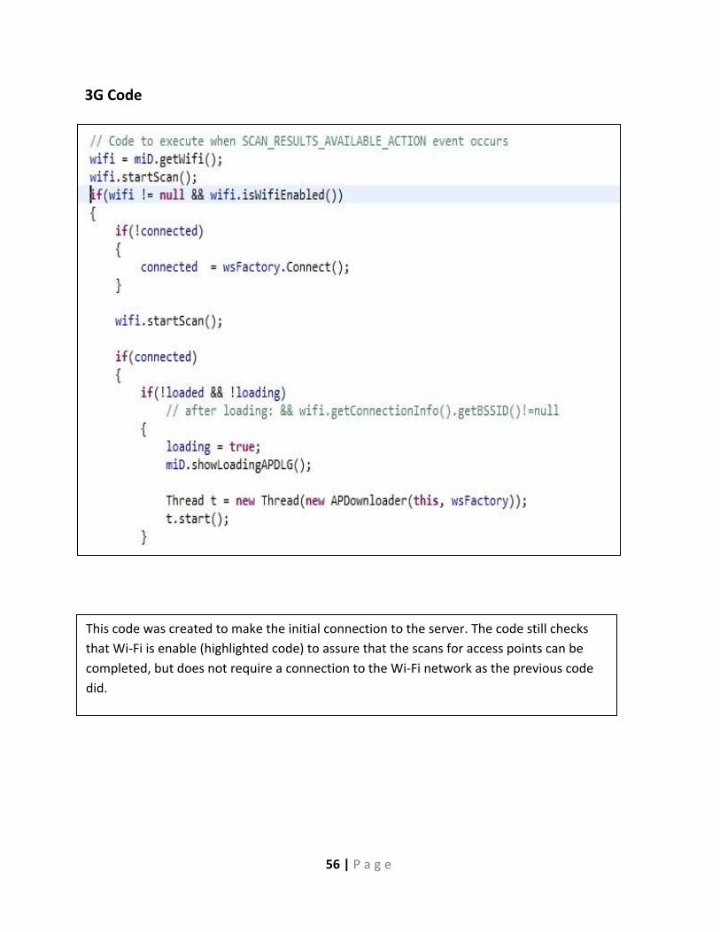
56 | P a g e
3G Code
This code was created to make the initial connection to the server. The code still checks
that Wi-Fi is enable (highlighted code) to assure that the scans for access points can be
completed, but does not require a connection to the Wi-Fi network as the previous code
did.

57 | P a g e
PCB Schematic

58 | P a g e
UDP Code

59 | P a g e
Ping Ad-Hoc

60 | P a g e
Ad-Hoc Explorer

61 | P a g e
MAC Address