Innovative Wrist Splint Design - University of Minnesota · Innovative Wrist Splint Design VOLUME...
47
Innovative Wrist Splint Design VOLUME II 5/7/13 Team: Paul Anhalt, Colton Borg, Garett Karalus, Erin Lemke, Chris Sluis, Tony Smith, Valerie Troutman and Mike Wasson Advisor: Dick Comben, Wood River Technologies
Transcript of Innovative Wrist Splint Design - University of Minnesota · Innovative Wrist Splint Design VOLUME...
Innovative Wrist Splint Design
VOLUME II
5/7/13
Team:
Paul Anhalt, Colton Borg, Garett Karalus, Erin Lemke,
Chris Sluis, Tony Smith, Valerie Troutman and Mike Wasson
Advisor:
Dick Comben, Wood River Technologies
Innovative Wrist Splint Design Report | Volume II 2
Table of Contents
1. Problem Definition Supporting Documents ................................................................. 3 1.1 Annotated Bibliography .................................................................................................................................... 3 1.2 Patent Search ..................................................................................................................................................... 9 1.3 User Need Research ......................................................................................................................................... 12 1.4 Concept Alternatives ....................................................................................................................................... 13 1.5 Concept Selection ............................................................................................................................................ 15
2. Design Description Supporting Documents .............................................................. 18 2.1 Manufacturing Plan (Product)........................................................................................................................ 18
2.1.1 Manufacturing Overview ......................................................................................................................... 18 2.1.2 Part Drawings ........................................................................................................................................... 18 2.1.3 Bill of Materials ........................................................................................................................................ 22 2.1.4 Manufacturing Procedure ........................................................................................................................ 22
3. Evaluation Supporting Documents .............................................................................. 23 3.1 Evaluation Reports .......................................................................................................................................... 23 3.2 Cost Analysis .................................................................................................................................................... 36 3.3 Environmental Impact Statement .................................................................................................................. 36 3.4 Regulatory and Safety Considerations ........................................................................................................... 37
4. List of Figures and Tables ............................................................................................... 38
5. Appendix ............................................................................................................................. 39 5.1 Patent First Pages ............................................................................................................................................ 40 5.2 Custumer Needs Supporting Documents ....................................................................................................... 45
Innovative Wrist Splint Design Report | Volume II 3
1. Problem Definition Supporting Documents The problem definition supporting documents includes all documents that provide background to claims made in the Problem Definition of Volume I. The documents include an annotated bibliography of all of the references cited in Volume I, details on the patent search that was completed, information on user need research, and explanation of concept alternatives, and details of the concept selection
1.1 Annotated Bibliography A variety of sources were used to gain background information as well as design requirements and user needs for a pneumatic splint. These sources include academic articles, patents, and interviews.
Plaster casts are shown to be the current treatment preference for fractured bones, and a variety of other orthopedic related ailments. Current casting methods are slow, do not allow to mistake correction, and can cause discomfort for the patient. Many temporary splinting options currently available to not provide the same strength and stability that plaster casts do. There is a need for a combination of the strength from plaster casts and the comfort and ease of use of temporary splinting options.
[1] Ansari, M.Z., Swarup, S., Ghani, R., Tovey, P., 1998, “Oscillating Saw Injuries During Removal of Plaster,” from http://www.ncbi.nlm.nih.gov/pubmed/10406417
Article discusses the fact that injuries may happen during the removal of a plaster cast. A yearlong study was to determine the actual amount of injuries and attempt to decide on the cause of the injuries.
It is important to note that plaster casts due in fact have a chance of injury during removal. Inexperience, dull blades and poorly trained personnel are all contributing factors to cast saw injuries.
[2] ASTM International, 2013, “F2878-10 Standard Test Method for Protective Clothing Material Resistance to Hypodermic Needle Puncture”, from http://enterprise.astm.org/filtrexx40.cgi?+REDLINE_PAGES/F2878.htm.
The ASTM standard describes the standard for protective clothing manufacturers should test the clothing and it provides a rating for force required to puncture for a material to pass. The material failure test utilized this information to determine whether the PAC cloth met the ASTM standard for puncture.
[3] Berman, A., Parks, B., 1990, “A Comparison of the Mechanical Properties of Fiberglass Cast Materials and Their Clinical Relevance,” Journal of Orthopaedic Trauma, 4(1), 85-92.
This article provides information on application times of plaster casts. This article provides set times and time until the cast can bear weight for a variety of plaster cast material brands.
Innovative Wrist Splint Design Report | Volume II 4
This article gave information that was used for the application time design requirement.
[4] “CES Edupack 2012,” Granta Design Limited, Version 11.9.9.
CES Edupack provides a lot of material information for common materials used in engineering. Material property charts can be made using it and indices of several materials can be compared on the same graph.
CES Edupack was used to find yield strength of a strong, tough material that can be used as a cover for something. Leather has properties that fit this description, so the ideal value for the yield strength of PAC cloth was estimated to be the same as leather. Several other materials were looked at using CES Edupack during this process.
[5] Charles, M. N. and Yen, D., Oct. 2000, “Properties of a Hybrid Plaster-Fibreglass Cast,” Canadian Journal of Surgery, 43 (5), 365-367.
This journal article describes the pros and cons of orthopedic plaster-of-paris casts and fiberglass casts. It uses the cons of each to warrant research on a hybrid cast made of both. An Instron model 1122 machine performed 3-point bending tests. Strength, cost, modulus of elasticity, and other values were determined from 10 tests. The results are shown with an explanation of why hybrid casts should be used. This article gives us bending strength and modulus of 3 different fiberglass and plaster casts as a benchmark for our design. It explains the results and gives insight to the clinical world surrounding casts. It also details some of the pros and cons of the casts we are trying to replace.
[6] Comben, D., 2013, Mechanical Engineering Senior Design Advisor, Wood River Technology, private communication.
Dick Comben has his masters in Mechanical Engineering and has advised Mechanical Engineering Senior Design projects in the past. He is the current advisor for the innovative splint design project. Mr. Comben has worked for large medical technology companies, and currently explores his own designs.
Dick recommended several design requirements and suggestions, as well as a wealth of background information on pneumatic splint design.
[7] Daugherty, David. Liesmann, R., 2006, “Vacuum Splint Device.” United States, 0155227. This patent describes a vacuum splint device for securely immobilizing an injured limb or other body part. This particular device utilizes pneumatics, and is comprised of a body containing loose particles. Air is vacuumed out once the device is placed on the injured body part to make the device rigid. Vacuum pressure is released to make the splint formable again.
Innovative Wrist Splint Design Report | Volume II 5
This patent details the design of a splint that uses negative pressure pneumatics. It was part of a number of patents that provided background information on prior art.
[8] Degun, M. Lain, A. Lennox, C., 2004, “Orthopaedic splint.“ United States, 0092853.
This patent describes an orthopedic splint that contains at least one rigid member and at least one inflatable air-bag that is fitted with a valve(s). These valves are used to inflate the airbags and also to allow pressure to release if pressure exceeds a set threshold. The splint is Velcro secured.
This patent details the design of a splint that uses positive pressure pneumatics. It was part of a number of patents that provided background information on prior art.
[9] Dincer, Derya M.D. 2007, “Injuries of the Hand and Wrist”, http://www.aiba.org/documents/ site1/commissions/medical/hand%20and%20wrist%20injuries.pdf
This document examines hand and wrist injuries in the sport of boxing. Information is given about the types of breaks, force required, healing time, and procedures.
The information used was the force required for a carpal fracture when the wrist is in dorsiflexion. 60% of all carpal injuries occur in this circumstance.
[10] Dunbar, R., & Crist, B., 2007, “Broken bones & injury.” From http://orhoinfo.aaos.org/menus/injury.cfm
The American Academy of Orthopedic Surgeons website gives a detailed summary of the many bone fractures that happen to humans. From different types of fractures to various forms of treatment, this site provides a very comprehensive explanation of the current fracture field.
This article gives a starting point for our project. It details current injuries and healing solutions. It clearly and simply explains fractures and current medical procedures to those without a medical background.
[11] Gurevitz, S. Tjtium, Y. Halperin, C. Eshkol, Z. Katz, K., 2004, “Correlation between experience in plaster-cast application and weight of plaster of Paris,” European Journal of Orthopedic Surgery and Traumatology, (14), 72-74.
This article provides the average weight of a plaster of paris cast used to treat wrist fractures. While the weight of a plaster cast varies depending on the severity of fracture and the skill of the medical professional providing the cast, an average weight can be determined.
This article provided important information used to discuss the environmental impact of current limb immobilization techniques.
[12] Hexcel Corp. 2000, “Hexweb Honeycomb Sandwich Design Technology.”
Innovative Wrist Splint Design Report | Volume II 6
This article is a summary of mathematical models developed specifically for honeycomb sandwich technology. The article has mathematical theories derived from basic mechanical deform theory that accurately model the deformation of honeycomb sandwich structures. It includes mathematical theory for several types of testing conditions along with example calculations to demonstrate how the equations given in the article can be used.
This article was used because it is the most relevant mathematical theory that applies to the sandwich structure used in our design. The equations given in the article specifically for the three point bending test can be used to attempt to verify the given mathematical model for our particular implementation of a honeycomb sandwich structure.
[13] Joseph, M., 2008, “Orthopedic System for Immobilizing and Supporting Body Parts” United States, 0319362.
This patent describes a three layer cast system for immobilizing limbs. The first layer provides padding and heat dissipation and is against the patient's skin. A second layer is formed from a thermoformable structural material. the material is formable when warm, and provides the rigid structure for the cast when cool. The third layer provides insulation for the second layer as well as general cushioning.
This patent details the design of a splint that uses thermomaterials. It was part of a number of patents that provided background information on prior art.
[14] Jus Semper Global Alliance, The, 2011, “Mexico’s Wage Gap Charts” Mexico, http://www.juss emper.org/Resources/Labour%20Resources/WGC/Resources/WagegapsMex2009.pdf
This website examines the wages associated with Mexico and other large manufacturing countries around the world. It describes the arguments for wage equalization amongst countries.
The information used from this article was to determine labor costs for the cost analysis section. Mexico and the United States wages were reported.
[15] Kline, D., 2013, Physical Therapy Student, University of Minnesota, private communication.
Ms. Kline was interviewed in order to gain a more diverse background on potential uses and viewpoints on a pneumatic splint. The interview was conducted through email.
This interview contributed to the diversity of background knowledge regarding splints. Since Ms. Kline is a student, the information gathered from the interview serves as general knowledge of orthopedics and was not used in determining design requirements.
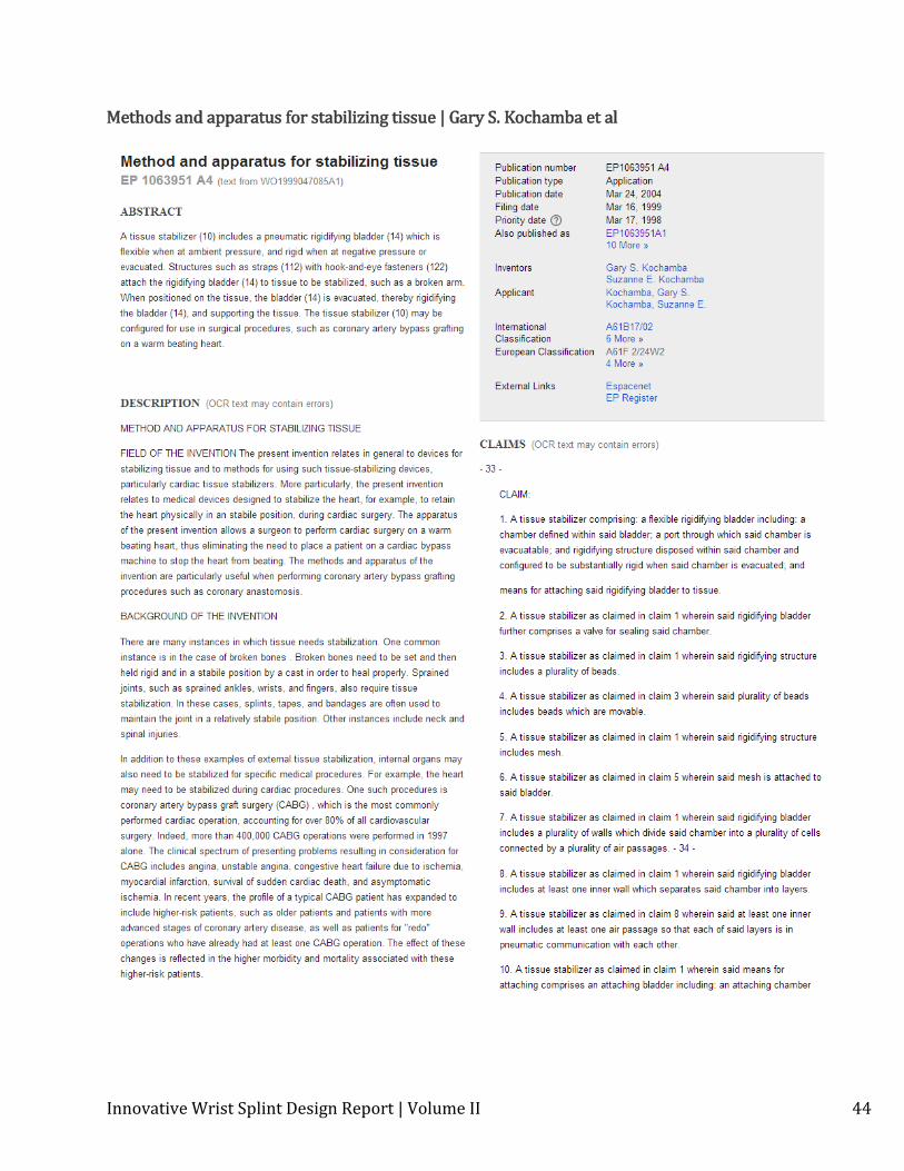
[16] Kochamba, G. Kochamba, S.,2004, “Methods and apparatus for stabilizing tissue” Europe, 1063951. This design is a negative pressure splint in which an air sealed bag filled with foam beads
Innovative Wrist Splint Design Report | Volume II 7
can be evacuated to become rigid. A small valve keeps air out of the sealed bag so it can remain rigid for extended periods of time. The sealed bag is not designed to overlap when it is folded, but instead has a Velcro® sheet that extends over the gap left open, and is secured tightly enough to protect that area from impact.
This patent details the design of a splint that uses negative pressure pneumatics. It was part of a number of patents that provided background information on prior art.
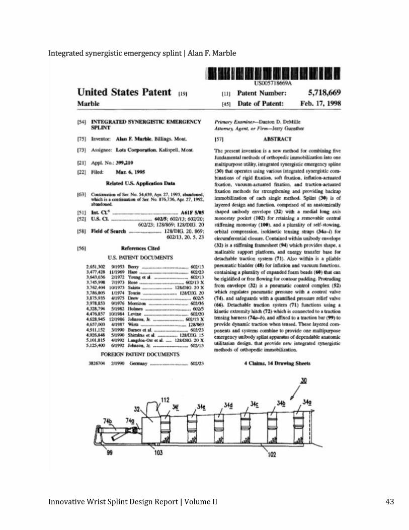
[17] Marble, A., 1998 , “Integrated synergistic emergency splint” United States, 5718669.
This patent covers a splint that combines negative pressure and positive pressure splint design. The negative pressure portion works by removing the air from an air bladder filled with foam beads. A small valve keeps air out of the bladder so that when it is evacuated, it remains rigid. It can also be inflated to provide the benefits of positive pressure splints if that is desirable in a given situation. It is designed to inflate around an arm properly so as to not put additional pressure on any single area. It also becomes thinner towards the edges that overlap, down to an almost sharp point, which removes the potential high pressure line that would occur of the seam were not tapered.
This patent details the design of a splint that uses both positive and negative pressure pneumatics. It was part of a number of patents that provided background information on prior art.
[18] McConnel, C., 2013, MD, Entira Family Clinics, private communication
Dr. McConnel provided a doctors perspective on current plaster casts and patient care. She also discussed proper care for fractures and the reasoning behind prescribed casts.
This provided general background knowledge on fractures, patient needs, and pricing of plaster casts.
[19] “Medical Devices”, 2013, from http://www.fda.gov/MedicalDevices/default.htm.
The Food and Drug Administration is the body that governs medical devices. For this reason, it is an agency with regulations that are very important to this project. The F.D.A. has a lot of information readily available about the process for having a medical device approved as well as how they are categorized.
[20] Mielke, C., and Finnet, C., 2013, Interim Chief of Staff at Shriner’s Hospital for Children, and OPA-C at Shriner’s Hospital for Children, private communication.
The topic of this meeting was to better understand current limb immobilization techniques used by those in the industry and areas that those techniques could be improved. Following this discussion, a tour and presentation of the casting room was given.
This meeting gave important insight into product design specifications. The hands-on experience in using fiberglass casting materials gave an appreciation for the small amount of time for error there is in the casting process. Also obtained information about cast saw accidents and the reality of them.
Innovative Wrist Splint Design Report | Volume II 8
[21] Nave, R. 2005, “HyperPhysics,” Georgia State University, from http://hyperphysics.phy-astr.gsu.edu/hbase/pman.html
This website provides basic information relating to the field of physics. It explains how to calculate fluid and air pressure, and it shows standard values for a lot of properties.
This information provided a result for the highest pressure a vacuum could exert on a pneumatic device. An ideal vacuum pressure for the splint is the minimum it can reach.
[22] New York State Osteoporosis Prevention and Education Program , 2011, “Wrist Fractures,” from http://www.nysopep.org/Consequences_WristFractures.shtm
This article provided an important statistic regarding the prevalence of wrist fractures in the United States annually. Wrist fractures are the most common bone fracture in the United States, with 400,000 occurrences annually.
This information was used in determining the environmental impact of current limb immobilization techniques, as well as provided motivation for the creation of a reusable splinting device.
[23] “Sam Splint” from http://www.sammedical.com/uploads/samsplint-brochure-2.pdf
This document details a current market splint solution called the Sam Splint. It is a splint for immobilizing skeletal and soft tissue injuries. Some key features of the Sam Splint include that it is lightweight, waterproof, reusable, compact and versatile.
This splint is a current reusable splint in the limb immobilization market. Though it does not use pneumatic technology, it is a viable competitor to our product.
[24] Singh, A., 2008, “Complications of Plaster Cast” from http://boneandspine.com/plaster-techniques/complications-of-plaster-cast/
A few concerns with plaster casts are raised in this article. It raises awareness about the possibility of reduced swelling making a cast have improper fit within two days of the original casting. It also brings concerns such as nerve damage and plaster to light.
This article helped with design constraints. It helped make us think about the inability of plaster casts to handle swelling as well the possibility of an improperly fitting cast can have on a fracture.
[25] Stern, W., 1907, “Plaster-of-Paris; The Effects of Various Sub-Stances Upon Its Rate of Setting and the Subsequent Strength and Durability of the Cast”, from http://jbjs.org/data/Journals/JBJS/1060/352.pdf
This article talks in great detail about the chemistry of plaster-of-paris. It talks about many of the theories that control the end effect of the plaster cast that happen during the casting process. It even goes on to talk about the overall strength of plaster casts.
Innovative Wrist Splint Design Report | Volume II 9
This is important to our research because it gives us a baseline for our strength requirement in our design specifications. Plaster-of-Paris casts have been a useful tool for fractures for a long time and any new splint should meet this design constraint.
[26] Werner, F. Short, W. Green, J. Evans, P. Walker, J., 2006, “Severity of Scapholunate Instability Is Related to Joint Anatomy and Congruency” The Journal of Hand Surgery, 32 (1), 55-60.
This article discusses how the anatomy of the distal radius and proximal scaphoid impact the stability of the scaphoid. The radius is a bone found in the forearm, and the scaphoid is part of the carpal bones in the wrist.
This article presented information on the anatomy of the wrist, and provided us with a benchmark value for the minimum radius of curvature that needs to be formed by the pneumatic splint.
1.2 Patent Search The objective of the patent search was to determine if our design is patentable. Furthermore it gave insight to current technologies and aided in brainstorming ideas. See section 5.2 of the Appendix for copies of the first page of each patent cited.
Google Scholar was used in order to search patents. The following keywords were used to find the patents discussed in the report.
Pneumatic Splint Cast Arm Honeycomb
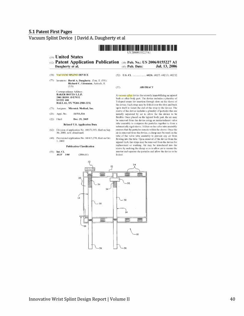
Vacuum Splint Device | US 2006 / 0155227 David A. Daugherty et al
A vacuum splint device for securely immobilizing an injured limb or other body part. T-shaped straps are inserted through slots on the sleeve of the device, to secure. The body of the device contains loose particles, air is vacuumed out once the device is placed on the injured body part to make the device rigid. A valve assembly, containing a filter that ensures that the particles remain in the body of the device, is used in the vacuuming process. A clamp is placed on the valve tube to prevent air from entering the device. Clamp is released to bring air back into the system and make the device flexible again. Straps can be washed and/or replaced.
Innovative Wrist Splint Design Report | Volume II 10
This patent described a negative pressure pneumatic splint. Gaining knowledge and information about currently patented negative pressure designs is key to understanding prior art. Per the selection criteria on the design matrix, a particle based design will not be pursued, and therefore this patent will not affect design patentability.
Key Features: Negative Pressure Reusable/disposable T shaped straps that are “threaded” around the device.
Velcro® secured. Particles within body, filter prevents particles from being vacuumed out Material on inner surface is textured/breathable for air flow
Orthopedic Splint | US 2004 / 0092853 Michael Degun, Lain Andrew, Craig Lennox
An orthopedic splint that contains at least one rigid member and at least one inflatable air-bag that is fitted with a valve(s). These valves are used to inflate the airbags and also to allow pressure to release if pressure exceeds a set threshold. This splint is Velcro® Secured.
This patent described a positive pressure pneumatic splint. Gaining knowledge and information about currently patented positive pressure designs is key to having a broad understanding prior art. Given that a negative pressure pneumatic design will be used on this splint, this patent will not affect design patentability.
Key Features: Positive Pressure Velcro® Fastened Rigid member with hemi-cylindrical inflatable air bag Valve allows release of air as swelling occurs (pressure relief valve and separate
inflation valve) Can be adjusted by patient
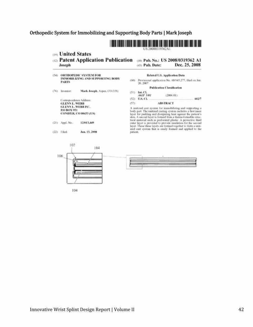
Orthopedic System for Immobilizing and Supporting Body Parts | US 2008 / 0319362
Mark Joseph
This patent describes a three layer cast system for immobilizing limbs. The first layer provides padding and heat dissipation and is against the patient's skin. A second layer is formed from a thermoformable structural material. The material is formable when warm, and provides the rigid structure for the cast when cool. The third layer provides insulation for the second layer as well as general cushioning.
Innovative Wrist Splint Design Report | Volume II 11
This patent described a three layer thermoformable splint. Gaining knowledge and information about currently patented splint designs is key to having a broad understanding prior art. Given that a design using thermoformable materials will not be used on the splint, this patent will not affect design.
Key Features: Three layers, including middle thermoforming material Adjustable securing mechanism allows practitioner to dictate how much the patient
can adjust the splint
Integrated Synergistic Emergency Splint | US 5,718,669
Alan F. Marble
This patent covers a splint that combines negative pressure and positive pressure splint design. The negative pressure portion works by removing the air from an air bladder filled with foam beads. A small valve keeps air out of the bladder so that when it is evacuated, it remains rigid. It is designed to inflate around an arm properly so as to not put additional pressure on any single area. It uses Velcro® straps all down the bladder to hold itself in place around the arm. It also becomes thinner towards the edges that overlap, down to an almost sharp point, which makes the overlapping seam much less noticeable, and removes the potential high pressure line that would occur of the seam were not tapered.
This patent described a synergistic positive and negative pressure pneumatic splint. Gaining knowledge and information about currently patented pneumatic splint designs is key to having a broad understanding prior art. Given that a design using solely negative pressure will be used on the splint, this patent will not affect design.
Key features: Combines positive and negative pressure Velcro® straps Designed only for emergency splint use Tapered overlapping edges
Methods and apparatus for stabilizing tissue | EP1063951 A4
Gary S. Kochamba et al
This design is a negative pressure splint. An air sealed bag filled with foam beads can be evacuated, and when it is, it becomes rigid. A small valve keeps air out of the sealed bag so it can remain rigid for extended periods of time. The design is not specific to arm injuries, as the patent also has pictures for neck, leg, and chest designs. The sealed bag is not designed to overlap when it is folded, but instead has a Velcro® sheet that extends over the “gap” left open, and is secured tightly enough to protect that area from impact. It is
Innovative Wrist Splint Design Report | Volume II 12
interesting to note that the area not covered by the sealed bag but instead by the Velcro® is more easily able to breathe, which could reduce the risk of heat rash significantly.
This patent described a negative pressure pneumatic splint. Gaining knowledge and information about currently patented negative pressure designs is key to understanding prior art. Per the selection criteria on the design matrix, a particle based design will not be pursued, and therefore this aspect of the patent will not affect design patentability. The open gap that is incorporated into this patented design poses a potential threat to the patentability of the splint.
Key features: Small bead negative pressure design Velcro® sheet Doesn’t fully wrap around limb
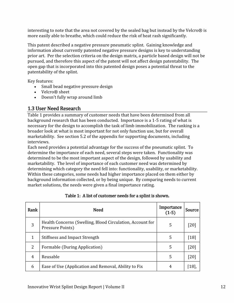
1.3 User Need Research Table 1 provides a summary of customer needs that have been determined from all background research that has been conducted. Importance is a 1-5 rating of what is necessary for the design to accomplish the task of limb immobilization. The ranking is a broader look at what is most important for not only function use, but for overall marketability. See section 5.2 of the appendix for supporting documents, including interviews. Each need provides a potential advantage for the success of the pneumatic splint. To determine the importance of each need, several steps were taken. Functionality was determined to be the most important aspect of the design, followed by usability and marketability. The level of importance of each customer need was determined by determining which category the need fell into: functionality, usability, or marketability. Within these categories, some needs had higher importance placed on them either by background information collected, or by being unique. By comparing needs to current market solutions, the needs were given a final importance rating.
Table 1: A list of customer needs for a splint is shown.
Rank Need Importance
(1-5) Source
3 Health Concerns (Swelling, Blood Circulation, Account for Pressure Points)
5 [20]
1 Stiffness and Impact Strength 5 [18]
2 Formable (During Application) 5 [20]
4 Reusable 5 [20]
6 Ease of Use (Application and Removal, Ability to Fix 4 [18],

Innovative Wrist Splint Design Report | Volume II 13
Mistakes, Time to Apply, Ability to Clean) [3]
5 Waterproof 4 [6]
8 Weight 2 [18]
10 Thickness / Bulkiness 2 [20]
7 Cost (Material, Labor) 2 [18]
9 Aesthetically Pleasing 2 [6]
11 Breathe-ability (air circulation, Temperature Control) 1 [20]
12 Hidden Valve 1 [6]
13 Storage Size (volume) 1 [20]
1.4 Concept Alternatives Plaster Cast This concept was evaluated to serve as our reference concept. This is a very common limb immobilization technique used. First cotton is placed on the affected limb and a wetted plaster roll is applied. After 20 minutes, the plaster cast is set, but will not be fully hardened for 24 hours. Removal of the cast entails the use of a special saw.
Figure 1: A drawing representing a current plaster cast is shown. Pneumatic Sandwich Structure The sandwich structure comprises of a filler core with two skins on each side. The structure is mildly formable, but after a vacuum is applied, the structure becomes rigid. Possibilities for the center include a honeycomb or composite structure.
Figure 2: Drawings of concepts that use a pneumatic sandwich structure are shown.
Skin
Honeycomb
Skin
Filler (Core)
Innovative Wrist Splint Design Report | Volume II 14
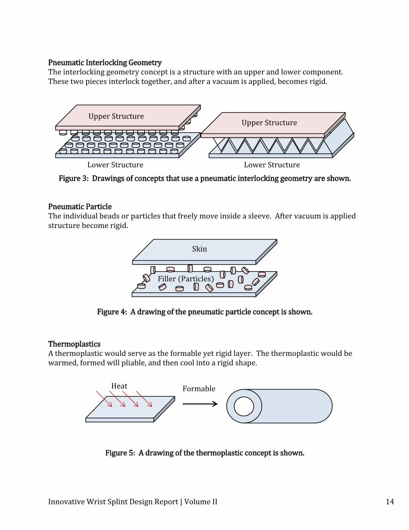
Pneumatic Interlocking Geometry The interlocking geometry concept is a structure with an upper and lower component. These two pieces interlock together, and after a vacuum is applied, becomes rigid.
Figure 3: Drawings of concepts that use a pneumatic interlocking geometry are shown.
Pneumatic Particle The individual beads or particles that freely move inside a sleeve. After vacuum is applied structure become rigid.
Figure 4: A drawing of the pneumatic particle concept is shown.
Thermoplastics A thermoplastic would serve as the formable yet rigid layer. The thermoplastic would be warmed, formed will pliable, and then cool into a rigid shape.
Figure 5: A drawing of the thermoplastic concept is shown.
Skin
Filler (Particles)
Lower Structure
Upper Structure Upper Structure
Lower Structure
Heat Formable
Innovative Wrist Splint Design Report | Volume II 15
1.5 Concept Selection Four different design concepts were compared to the current plaster cast. The pneumatic sandwich structure has a honeycomb core, and becomes rigid once negative pressure is applied. The pneumatic interlocking structure is composed of an upper and lower component with interlock and become rigid once negative pressure is applied. The pneumatic particle design is a sleeve containing individual beads or particles that becomes rigid after negative pressure is applied. The fourth concept compared is a thermoplastic that would be pliable when warm and would retain its shape after the material cools.
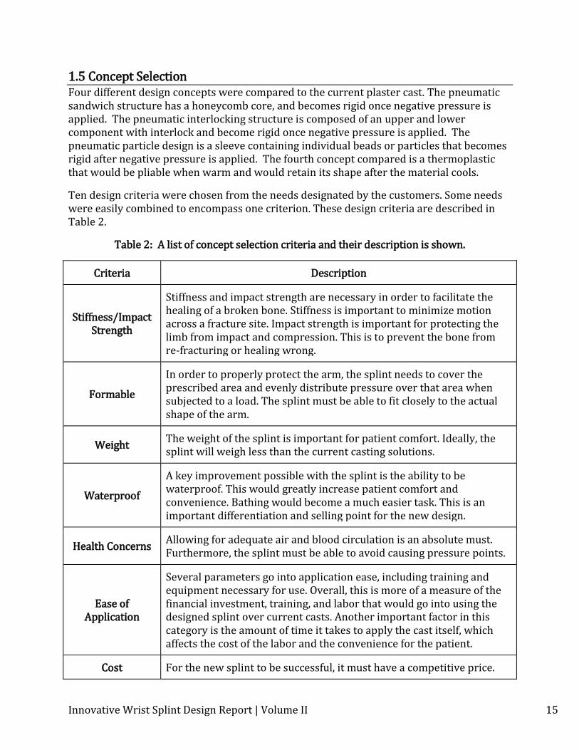
Ten design criteria were chosen from the needs designated by the customers. Some needs were easily combined to encompass one criterion. These design criteria are described in Table 2.
Table 2: A list of concept selection criteria and their description is shown.
Criteria Description
Stiffness/Impact Strength
Stiffness and impact strength are necessary in order to facilitate the healing of a broken bone. Stiffness is important to minimize motion across a fracture site. Impact strength is important for protecting the limb from impact and compression. This is to prevent the bone from re-fracturing or healing wrong.
Formable
In order to properly protect the arm, the splint needs to cover the prescribed area and evenly distribute pressure over that area when subjected to a load. The splint must be able to fit closely to the actual shape of the arm.
Weight The weight of the splint is important for patient comfort. Ideally, the splint will weigh less than the current casting solutions.
Waterproof
A key improvement possible with the splint is the ability to be waterproof. This would greatly increase patient comfort and convenience. Bathing would become a much easier task. This is an important differentiation and selling point for the new design.
Health Concerns Allowing for adequate air and blood circulation is an absolute must. Furthermore, the splint must be able to avoid causing pressure points.
Ease of Application
Several parameters go into application ease, including training and equipment necessary for use. Overall, this is more of a measure of the financial investment, training, and labor that would go into using the designed splint over current casts. Another important factor in this category is the amount of time it takes to apply the cast itself, which affects the cost of the labor and the convenience for the patient.
Cost For the new splint to be successful, it must have a competitive price.
Innovative Wrist Splint Design Report | Volume II 16
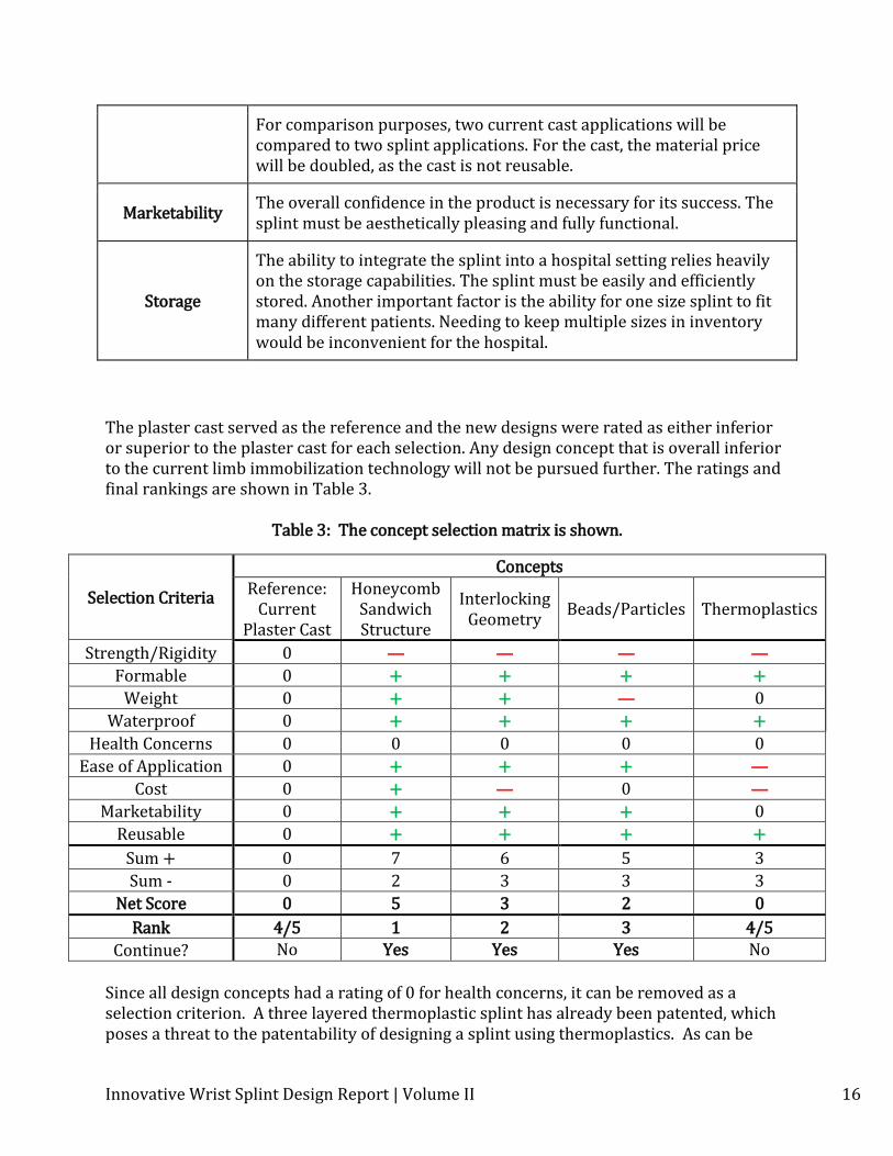
For comparison purposes, two current cast applications will be compared to two splint applications. For the cast, the material price will be doubled, as the cast is not reusable.
Marketability The overall confidence in the product is necessary for its success. The splint must be aesthetically pleasing and fully functional.
Storage
The ability to integrate the splint into a hospital setting relies heavily on the storage capabilities. The splint must be easily and efficiently stored. Another important factor is the ability for one size splint to fit many different patients. Needing to keep multiple sizes in inventory would be inconvenient for the hospital.
The plaster cast served as the reference and the new designs were rated as either inferior or superior to the plaster cast for each selection. Any design concept that is overall inferior to the current limb immobilization technology will not be pursued further. The ratings and final rankings are shown in Table 3.
Table 3: The concept selection matrix is shown.
Selection Criteria
Concepts
Reference: Current
Plaster Cast
Honeycomb Sandwich Structure
Interlocking Geometry
Beads/Particles Thermoplastics
Strength/Rigidity 0 — — — —
Formable 0 + + + +
Weight 0 + + — 0
Waterproof 0 + + + +
Health Concerns 0 0 0 0 0
Ease of Application 0 + + + —
Cost 0 + — 0 —
Marketability 0 + + + 0
Reusable 0 + + + +
Sum + 0 7 6 5 3
Sum - 0 2 3 3 3
Net Score 0 5 3 2 0
Rank 4/5 1 2 3 4/5
Continue? No Yes Yes Yes No
Since all design concepts had a rating of 0 for health concerns, it can be removed as a selection criterion. A three layered thermoplastic splint has already been patented, which poses a threat to the patentability of designing a splint using thermoplastics. As can be
Innovative Wrist Splint Design Report | Volume II 17
seen in Table 3, the thermoplastics option had no pros over current methods used. These two items led to the decision to remove thermoplastics as a viable design option, and to focus on the remaining concepts.
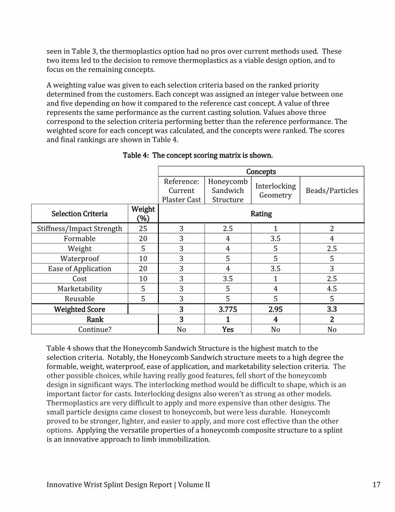
A weighting value was given to each selection criteria based on the ranked priority determined from the customers. Each concept was assigned an integer value between one and five depending on how it compared to the reference cast concept. A value of three represents the same performance as the current casting solution. Values above three correspond to the selection criteria performing better than the reference performance. The weighted score for each concept was calculated, and the concepts were ranked. The scores and final rankings are shown in Table 4.
Table 4: The concept scoring matrix is shown.
Concepts
Reference: Current
Plaster Cast
Honeycomb Sandwich Structure
Interlocking Geometry
Beads/Particles
Selection Criteria Weight
(%) Rating
Stiffness/Impact Strength 25 3 2.5 1 2
Formable 20 3 4 3.5 4
Weight 5 3 4 5 2.5
Waterproof 10 3 5 5 5
Ease of Application 20 3 4 3.5 3
Cost 10 3 3.5 1 2.5
Marketability 5 3 5 4 4.5
Reusable 5 3 5 5 5
Weighted Score
3 3.775 2.95 3.3
Rank 3 1 4 2
Continue? No Yes No No Table 4 shows that the Honeycomb Sandwich Structure is the highest match to the selection criteria. Notably, the Honeycomb Sandwich structure meets to a high degree the formable, weight, waterproof, ease of application, and marketability selection criteria. The other possible choices, while having really good features, fell short of the honeycomb design in significant ways. The interlocking method would be difficult to shape, which is an important factor for casts. Interlocking designs also weren't as strong as other models. Thermoplastics are very difficult to apply and more expensive than other designs. The small particle designs came closest to honeycomb, but were less durable. Honeycomb proved to be stronger, lighter, and easier to apply, and more cost effective than the other options. Applying the versatile properties of a honeycomb composite structure to a splint is an innovative approach to limb immobilization.
Innovative Wrist Splint Design Report | Volume II 18
2. Design Description Supporting Documents
2.1 Manufacturing Plan (Product) The innovative splint is manufactured using a straightforward procedure. The materials required are easily obtainable, commercially produced products. Capital investment for low capacity manufacture is minimal and can be carried out by an individual. For high capacity manufacture, the process could be automated.
2.1.1 Manufacturing Overview The innovative splint is composed of flex-core honeycomb material, structural mesh materials, a two-way flow control valve, 0.125” plastic tubing, and an airtight outer bag. The honeycomb material is cut into the correct geometry and dimensions. The honeycomb is then given a light sanding and filed on opposite edges to create a diamond shaped cross-section. The mesh material is then added to the top and bottom of the honeycomb. These core materials are then sewn into an airtight bag and the valve is attached by cutting a hole in the bag. Once all core materials are set, the bag is heat-sealed and the valve is secured using adhesive. Extra padding and a decorative cloth cover can be constructed and attached to an applied splint.
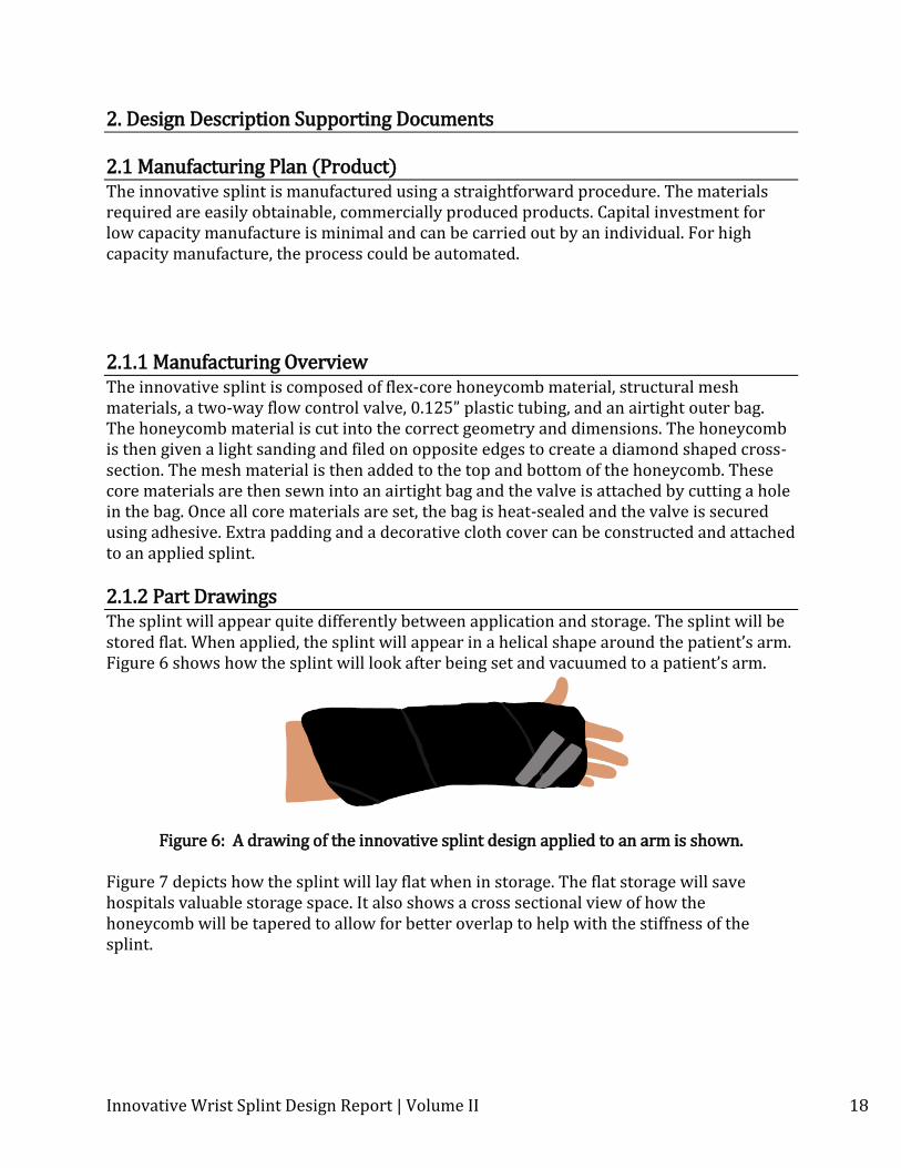
2.1.2 Part Drawings The splint will appear quite differently between application and storage. The splint will be stored flat. When applied, the splint will appear in a helical shape around the patient’s arm. Figure 6 shows how the splint will look after being set and vacuumed to a patient’s arm.
Figure 6: A drawing of the innovative splint design applied to an arm is shown.
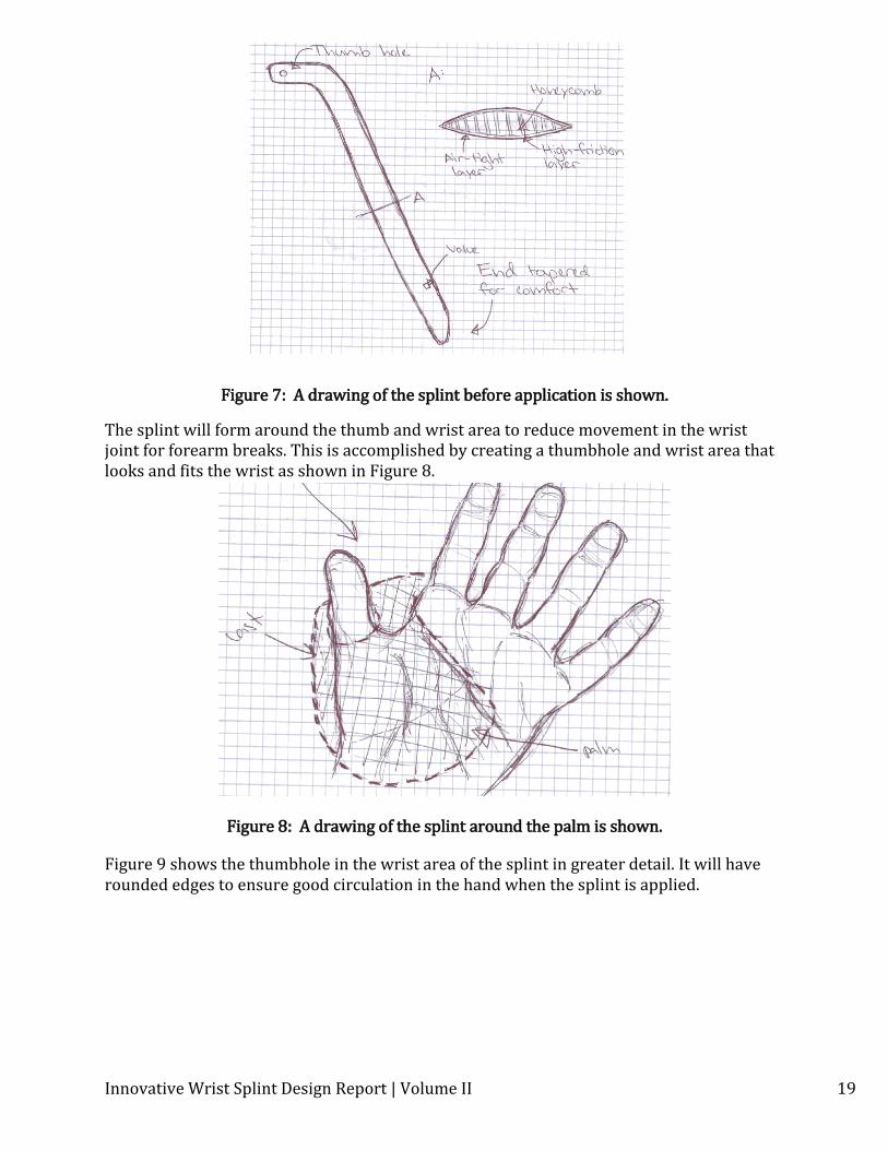
Figure 7 depicts how the splint will lay flat when in storage. The flat storage will save hospitals valuable storage space. It also shows a cross sectional view of how the honeycomb will be tapered to allow for better overlap to help with the stiffness of the splint.
Innovative Wrist Splint Design Report | Volume II 19
Figure 7: A drawing of the splint before application is shown.
The splint will form around the thumb and wrist area to reduce movement in the wrist joint for forearm breaks. This is accomplished by creating a thumbhole and wrist area that looks and fits the wrist as shown in Figure 8.
Figure 8: A drawing of the splint around the palm is shown.
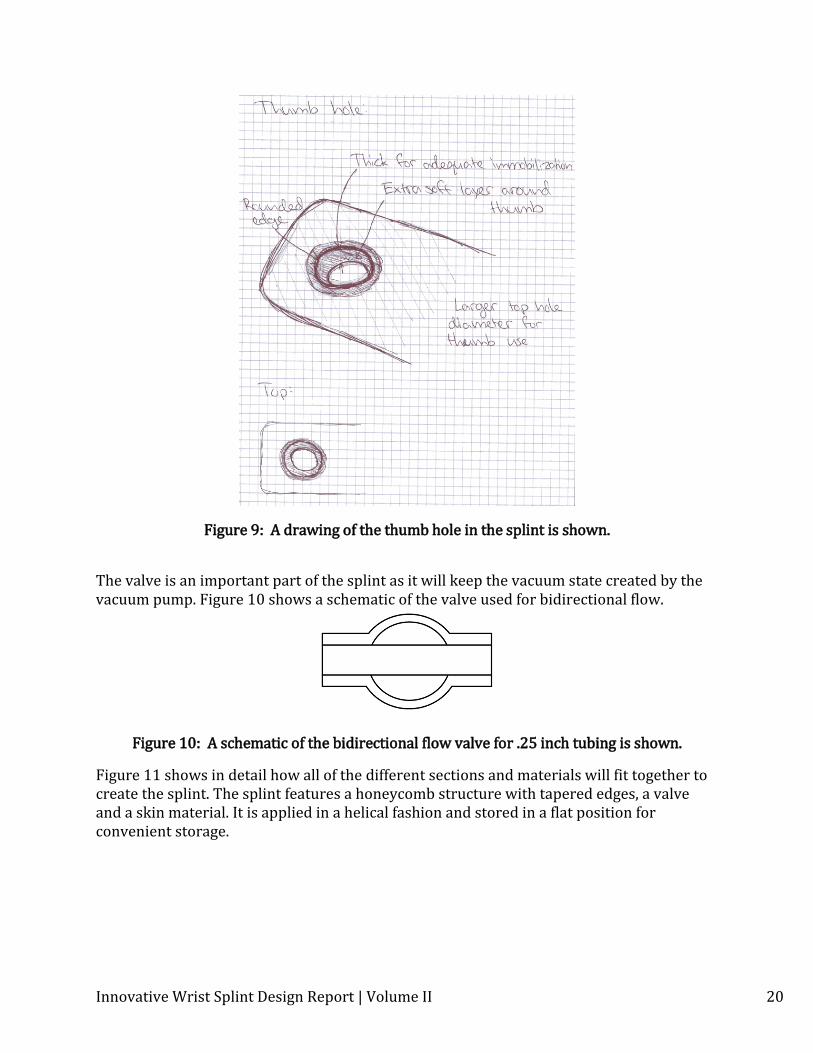
Figure 9 shows the thumbhole in the wrist area of the splint in greater detail. It will have rounded edges to ensure good circulation in the hand when the splint is applied.
Innovative Wrist Splint Design Report | Volume II 20
Figure 9: A drawing of the thumb hole in the splint is shown.
The valve is an important part of the splint as it will keep the vacuum state created by the vacuum pump. Figure 10 shows a schematic of the valve used for bidirectional flow.
Figure 10: A schematic of the bidirectional flow valve for .25 inch tubing is shown.
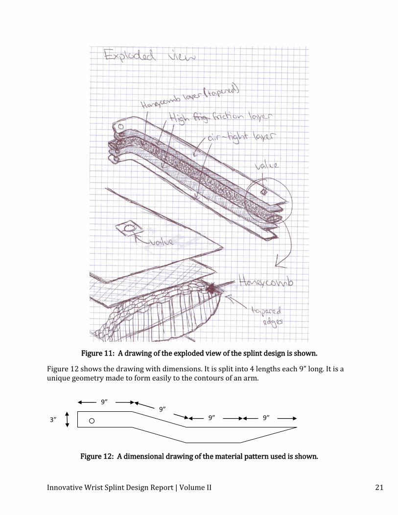
Figure 11 shows in detail how all of the different sections and materials will fit together to create the splint. The splint features a honeycomb structure with tapered edges, a valve and a skin material. It is applied in a helical fashion and stored in a flat position for convenient storage.
Innovative Wrist Splint Design Report | Volume II 21
Figure 11: A drawing of the exploded view of the splint design is shown.
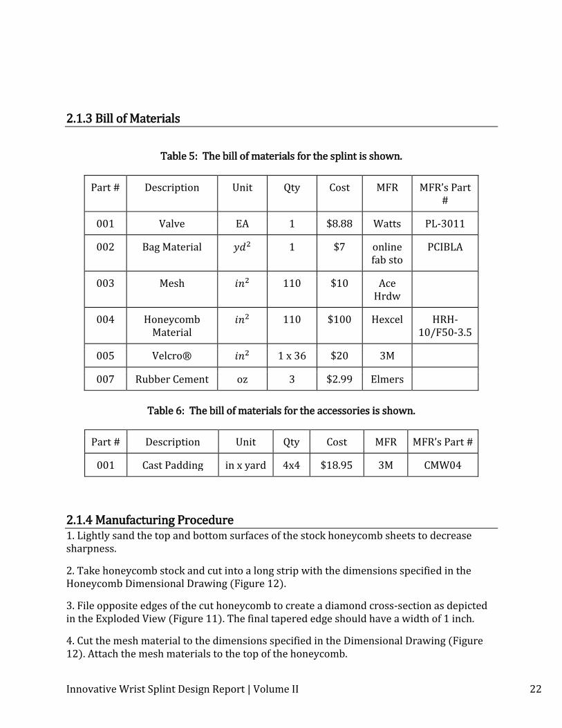
Figure 12 shows the drawing with dimensions. It is split into 4 lengths each 9” long. It is a unique geometry made to form easily to the contours of an arm.
Figure 12: A dimensional drawing of the material pattern used is shown.
9” 9”
9” 9” 3”
Innovative Wrist Splint Design Report | Volume II 22
2.1.3 Bill of Materials
Table 5: The bill of materials for the splint is shown.
Part # Description Unit Qty Cost MFR MFR’s Part #
001 Valve EA 1 $8.88 Watts PL-3011
002 Bag Material
1
$7
online fab sto
PCIBLA
003 Mesh 110 $10 Ace Hrdw
004 Honeycomb Material
110
$100 Hexcel HRH-10/F50-3.5
005 Velcro® 1 x 36 $20 3M
007 Rubber Cement oz 3 $2.99 Elmers
Table 6: The bill of materials for the accessories is shown.
Part # Description Unit Qty Cost MFR MFR’s Part #
001 Cast Padding in x yard 4x4 $18.95 3M CMW04
2.1.4 Manufacturing Procedure 1. Lightly sand the top and bottom surfaces of the stock honeycomb sheets to decrease sharpness.
2. Take honeycomb stock and cut into a long strip with the dimensions specified in the Honeycomb Dimensional Drawing (Figure 12).
3. File opposite edges of the cut honeycomb to create a diamond cross-section as depicted in the Exploded View (Figure 11). The final tapered edge should have a width of 1 inch.
4. Cut the mesh material to the dimensions specified in the Dimensional Drawing (Figure 12). Attach the mesh materials to the top of the honeycomb.
Innovative Wrist Splint Design Report | Volume II 23
5. Cut the bag material to the dimensions specified in the Dimensional Drawing (Figure 12).
6. Place a layer of the bag material above and below the core materials. Seal the bag layers together on all edges and around thumb hole.
7. Seal all edges using material adhesive.
8. Cut small hole in material at end of sealed bag, at the location shown in Dimensional Drawing (Figure 12)
9. Insert flow control valve and attach assembly to bag using adhesive.
**Additional padding and decorative cloth cover manufacture separately.
3. Evaluation Supporting Documents
3.1 Evaluation Reports Material Failure
Introduction The bag material holds the honeycomb core in place while keeping the vacuum from equalizing with the ambient pressure. The outside bag material of the splint can’t be compromised with a hole punctured in the side. A puncture would make the product fail.
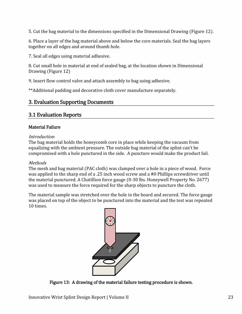
Methods The mesh and bag material (PAC cloth) was clamped over a hole in a piece of wood. Force was applied to the sharp end of a .25 inch wood screw and a #0 Phillips screwdriver until the material punctured. A Chatillion force gauge (0-30 lbs. Honeywell Property No. 2677) was used to measure the force required for the sharp objects to puncture the cloth.
The material sample was stretched over the hole in the board and secured. The force gauge was placed on top of the object to be punctured into the material and the test was repeated 10 times.
Figure 13: A drawing of the material failure testing procedure is shown.
Innovative Wrist Splint Design Report | Volume II 24
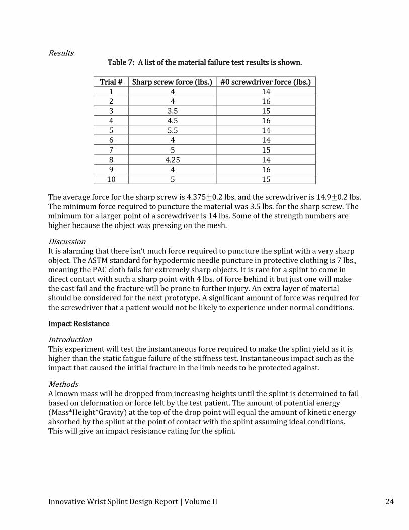
Results Table 7: A list of the material failure test results is shown.
Trial # Sharp screw force (lbs.) #0 screwdriver force (lbs.)
1 4 14 2 4 16 3 3.5 15 4 4.5 16 5 5.5 14 6 4 14 7 5 15 8 4.25 14 9 4 16
10 5 15
The average force for the sharp screw is 4.375±0.2 lbs. and the screwdriver is 14.9±0.2 lbs. The minimum force required to puncture the material was 3.5 lbs. for the sharp screw. The minimum for a larger point of a screwdriver is 14 lbs. Some of the strength numbers are higher because the object was pressing on the mesh.
Discussion It is alarming that there isn’t much force required to puncture the splint with a very sharp object. The ASTM standard for hypodermic needle puncture in protective clothing is 7 lbs., meaning the PAC cloth fails for extremely sharp objects. It is rare for a splint to come in direct contact with such a sharp point with 4 lbs. of force behind it but just one will make the cast fail and the fracture will be prone to further injury. An extra layer of material should be considered for the next prototype. A significant amount of force was required for the screwdriver that a patient would not be likely to experience under normal conditions.
Impact Resistance
Introduction This experiment will test the instantaneous force required to make the splint yield as it is higher than the static fatigue failure of the stiffness test. Instantaneous impact such as the impact that caused the initial fracture in the limb needs to be protected against.
Methods A known mass will be dropped from increasing heights until the splint is determined to fail based on deformation or force felt by the test patient. The amount of potential energy (Mass*Height*Gravity) at the top of the drop point will equal the amount of kinetic energy absorbed by the splint at the point of contact with the splint assuming ideal conditions. This will give an impact resistance rating for the splint.
Innovative Wrist Splint Design Report | Volume II 25
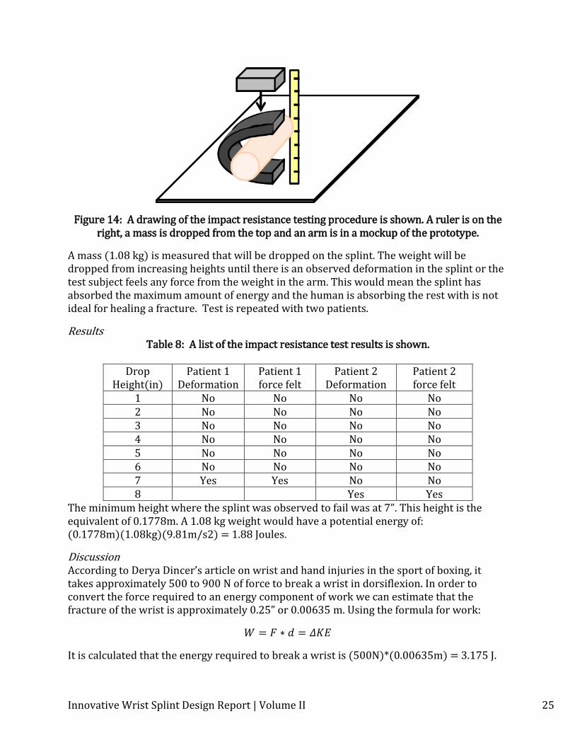
Figure 14: A drawing of the impact resistance testing procedure is shown. A ruler is on the right, a mass is dropped from the top and an arm is in a mockup of the prototype.
A mass (1.08 kg) is measured that will be dropped on the splint. The weight will be dropped from increasing heights until there is an observed deformation in the splint or the test subject feels any force from the weight in the arm. This would mean the splint has absorbed the maximum amount of energy and the human is absorbing the rest with is not ideal for healing a fracture. Test is repeated with two patients.
Results Table 8: A list of the impact resistance test results is shown.
Drop
Height(in) Patient 1
Deformation Patient 1 force felt
Patient 2 Deformation
Patient 2 force felt
1 No No No No 2 No No No No 3 No No No No 4 No No No No 5 No No No No 6 No No No No 7 Yes Yes No No 8 Yes Yes
The minimum height where the splint was observed to fail was at 7”. This height is the equivalent of 0.1778m. A 1.08 kg weight would have a potential energy of: (0.1778m)(1.08kg)(9.81m/s2) = 1.88 Joules.
Discussion According to Derya Dincer’s article on wrist and hand injuries in the sport of boxing, it takes approximately 500 to 900 N of force to break a wrist in dorsiflexion. In order to convert the force required to an energy component of work we can estimate that the fracture of the wrist is approximately 0.25” or 0.00635 m. Using the formula for work:
It is calculated that the energy required to break a wrist is (500N)*(0.00635m) = 3.175 J.
Innovative Wrist Splint Design Report | Volume II 26
The innovative splint is capable of absorbing nearly 60% of this energy before transferring it to the patient’s limb. The splint succeeded in this impact test based on specifications determined in the design requirements.
Stiffness
Introduction The splint has to be rigid to protect the limb from new micro fractures and immobilize the limb to promote healing. The stiffness property of the splint is the measure of how much the splint will deflect with an applied force in its vacuumed state. The stiffness can then be used to find the modulus of elasticity of the splint after it is vacuumed, which can be compared to current casts. In order for the splint’s design to be useful, it needs to have a high modulus comparable to current casts.
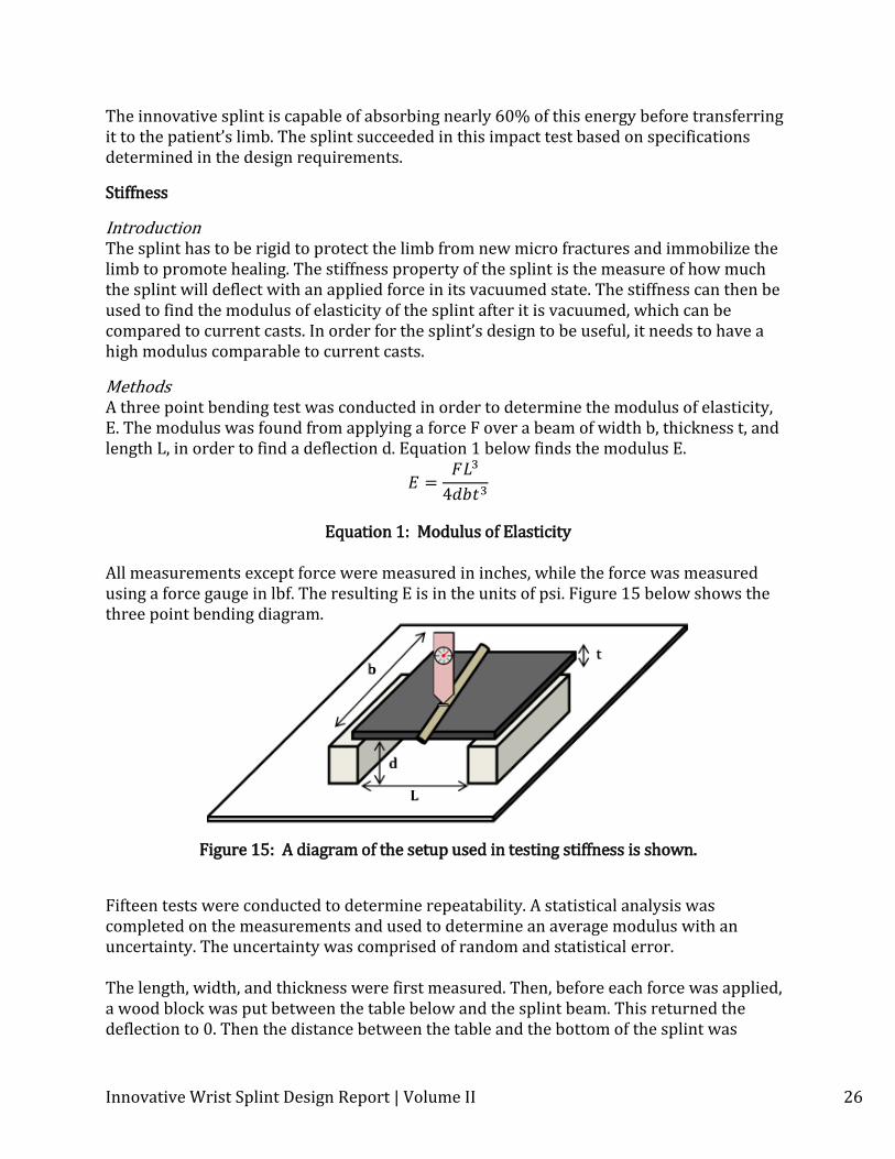
Methods A three point bending test was conducted in order to determine the modulus of elasticity, E. The modulus was found from applying a force F over a beam of width b, thickness t, and length L, in order to find a deflection d. Equation 1 below finds the modulus E.
4
Equation 1: Modulus of Elasticity
All measurements except force were measured in inches, while the force was measured using a force gauge in lbf. The resulting E is in the units of psi. Figure 15 below shows the three point bending diagram.
Figure 15: A diagram of the setup used in testing stiffness is shown.
Fifteen tests were conducted to determine repeatability. A statistical analysis was completed on the measurements and used to determine an average modulus with an uncertainty. The uncertainty was comprised of random and statistical error. The length, width, and thickness were first measured. Then, before each force was applied, a wood block was put between the table below and the splint beam. This returned the deflection to 0. Then the distance between the table and the bottom of the splint was
Innovative Wrist Splint Design Report | Volume II 27
measured. The splint was vacuumed and the force was applied to the stiff splint. Once the force gauge reached the desired amount and the deflection was measured, the force was withdrawn. A caliper was used to measure the new distance from the bottom of the splint to the table just before the force was withdrawn. To get the deflection, the new distance was subtracted from the initial distance. This procedure was completed for each trial. Now by using Equation 1, the resulting elastic modulus can be found from each trial.
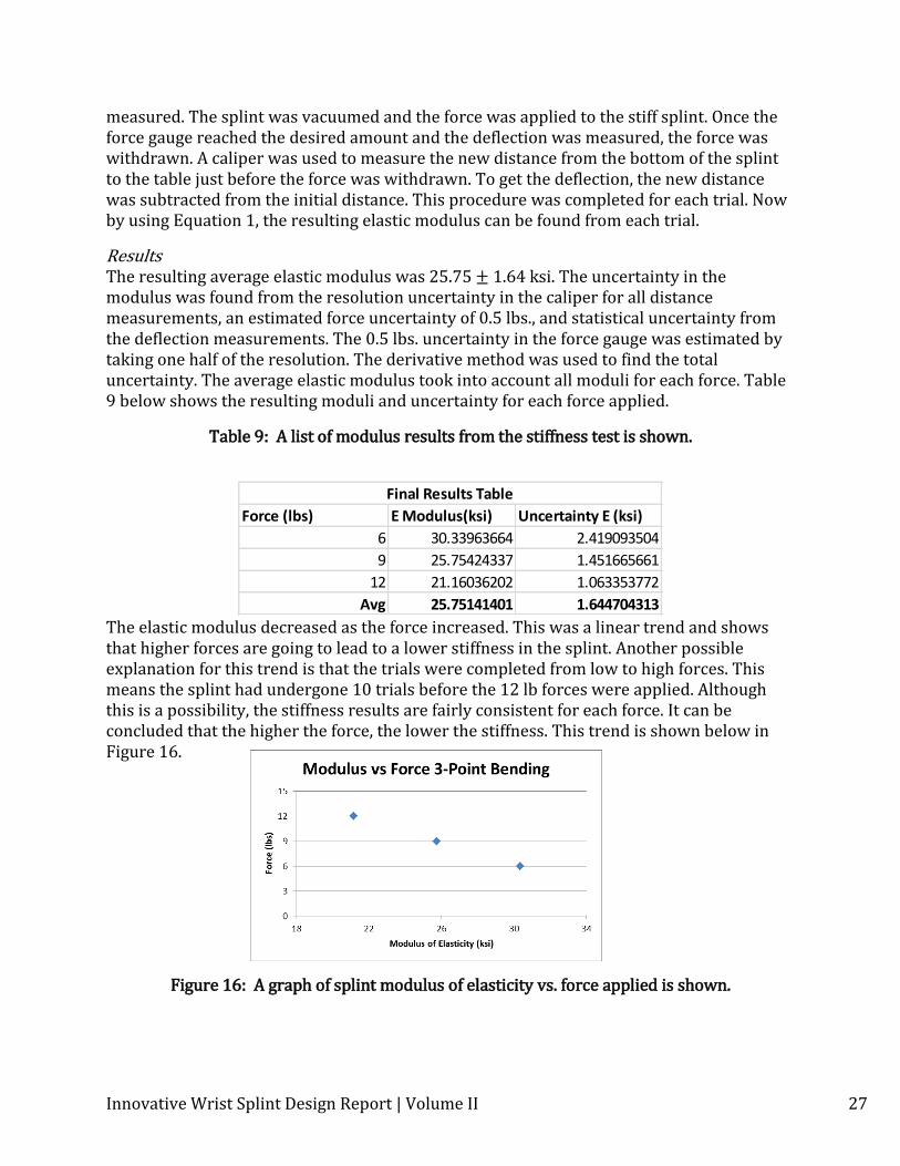
Results The resulting average elastic modulus was 25.75 ± 1.64 ksi. The uncertainty in the modulus was found from the resolution uncertainty in the caliper for all distance measurements, an estimated force uncertainty of 0.5 lbs., and statistical uncertainty from the deflection measurements. The 0.5 lbs. uncertainty in the force gauge was estimated by taking one half of the resolution. The derivative method was used to find the total uncertainty. The average elastic modulus took into account all moduli for each force. Table 9 below shows the resulting moduli and uncertainty for each force applied.
Table 9: A list of modulus results from the stiffness test is shown.
The elastic modulus decreased as the force increased. This was a linear trend and shows that higher forces are going to lead to a lower stiffness in the splint. Another possible explanation for this trend is that the trials were completed from low to high forces. This means the splint had undergone 10 trials before the 12 lb forces were applied. Although this is a possibility, the stiffness results are fairly consistent for each force. It can be concluded that the higher the force, the lower the stiffness. This trend is shown below in Figure 16.
Figure 16: A graph of splint modulus of elasticity vs. force applied is shown.
Force (lbs) E Modulus(ksi) Uncertainty E (ksi)
6 30.33963664 2.419093504
9 25.75424337 1.451665661
12 21.16036202 1.063353772
Avg 25.75141401 1.644704313
Final Results Table
Innovative Wrist Splint Design Report | Volume II 28
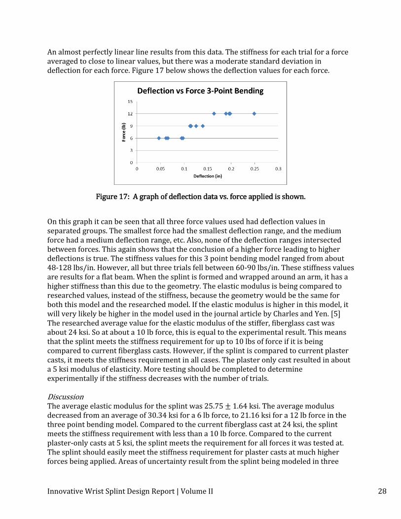
An almost perfectly linear line results from this data. The stiffness for each trial for a force averaged to close to linear values, but there was a moderate standard deviation in deflection for each force. Figure 17 below shows the deflection values for each force.
Figure 17: A graph of deflection data vs. force applied is shown.
On this graph it can be seen that all three force values used had deflection values in separated groups. The smallest force had the smallest deflection range, and the medium force had a medium deflection range, etc. Also, none of the deflection ranges intersected between forces. This again shows that the conclusion of a higher force leading to higher deflections is true. The stiffness values for this 3 point bending model ranged from about 48-128 lbs/in. However, all but three trials fell between 60-90 lbs/in. These stiffness values are results for a flat beam. When the splint is formed and wrapped around an arm, it has a higher stiffness than this due to the geometry. The elastic modulus is being compared to researched values, instead of the stiffness, because the geometry would be the same for both this model and the researched model. If the elastic modulus is higher in this model, it will very likely be higher in the model used in the journal article by Charles and Yen. [5] The researched average value for the elastic modulus of the stiffer, fiberglass cast was about 24 ksi. So at about a 10 lb force, this is equal to the experimental result. This means that the splint meets the stiffness requirement for up to 10 lbs of force if it is being compared to current fiberglass casts. However, if the splint is compared to current plaster casts, it meets the stiffness requirement in all cases. The plaster only cast resulted in about a 5 ksi modulus of elasticity. More testing should be completed to determine experimentally if the stiffness decreases with the number of trials. Discussion The average elastic modulus for the splint was 25.75 ± 1.64 ksi. The average modulus decreased from an average of 30.34 ksi for a 6 lb force, to 21.16 ksi for a 12 lb force in the three point bending model. Compared to the current fiberglass cast at 24 ksi, the splint meets the stiffness requirement with less than a 10 lb force. Compared to the current plaster-only casts at 5 ksi, the splint meets the requirement for all forces it was tested at. The splint should easily meet the stiffness requirement for plaster casts at much higher forces being applied. Areas of uncertainty result from the splint being modeled in three
Innovative Wrist Splint Design Report | Volume II 29
point-bending without being in its formed position. If it was formed, the stiffness would increase possibly changing the results for the modulus when certain forces are applied.
Mathematical Model Verification
Methods In honeycomb sandwich structure theory, a different method for determining the strength of a sandwich structure is used. It depends both on the properties of the skin material and that of the honeycomb itself.
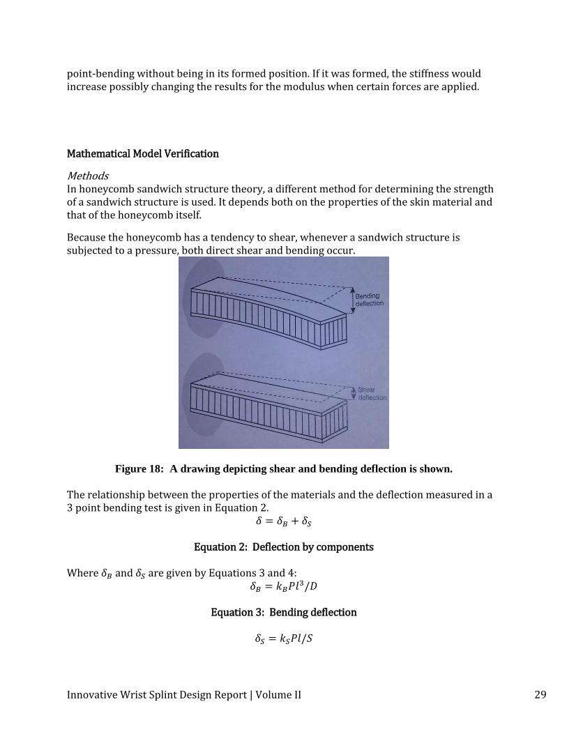
Because the honeycomb has a tendency to shear, whenever a sandwich structure is subjected to a pressure, both direct shear and bending occur.
Figure 18: A drawing depicting shear and bending deflection is shown.
The relationship between the properties of the materials and the deflection measured in a 3 point bending test is given in Equation 2.
Equation 2: Deflection by components
Where and are given by Equations 3 and 4:
/
Equation 3: Bending deflection
/
Innovative Wrist Splint Design Report | Volume II 30
Equation 4: Shear deflection
/2
Equation 5: Bending modulus
Equation 6: Shear modulus
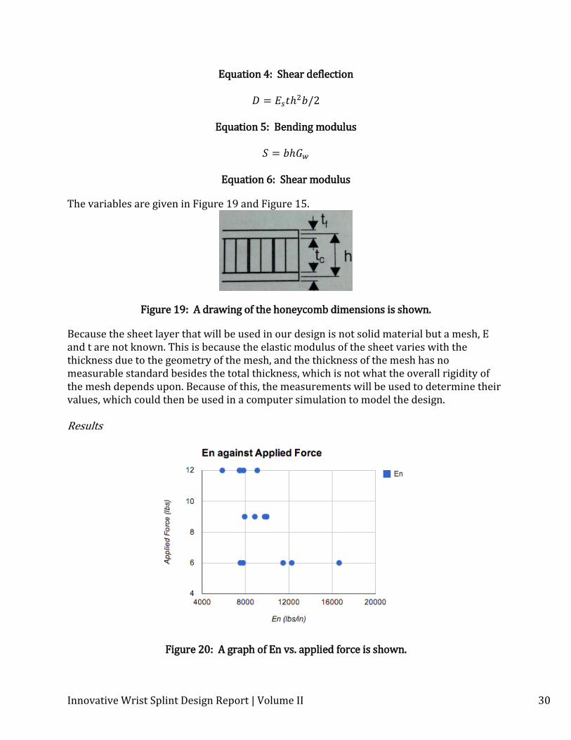
The variables are given in Figure 19 and Figure 15.
Figure 19: A drawing of the honeycomb dimensions is shown.
Because the sheet layer that will be used in our design is not solid material but a mesh, E and t are not known. This is because the elastic modulus of the sheet varies with the thickness due to the geometry of the mesh, and the thickness of the mesh has no measurable standard besides the total thickness, which is not what the overall rigidity of the mesh depends upon. Because of this, the measurements will be used to determine their values, which could then be used in a computer simulation to model the design. Results
Figure 20: A graph of En vs. applied force is shown.
Innovative Wrist Splint Design Report | Volume II 31
The average value of En was found to be 9331 lbs/in. The error of this value has no meaning because this is the value that will be used in simulation. If a sensitivity analysis were to be done on the simulations, that result would be relevant, but given that the uncertainty of several material properties cannot be determined without months of testing, such results would have an unknown accuracy.
Radius of Curvature
Introduction The ability to form the splint to the contours of an arm is fundamental to complete limb immobilization and proper healing. The wrist is the portion of the arm that requires the smallest radius of curvature. From an article in The Journal of Hand Surgery, it was determined that for the typical adult and adolescent a minimum radius of curvature of .625 inches would allow the splint to closely follow the contours of the wrist. [26]
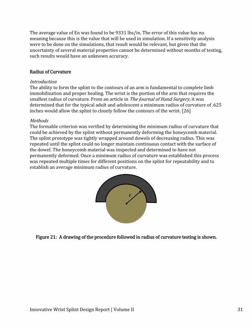
Methods The formable criterion was verified by determining the minimum radius of curvature that could be achieved by the splint without permanently deforming the honeycomb material. The splint prototype was tightly wrapped around dowels of decreasing radius. This was repeated until the splint could no longer maintain continuous contact with the surface of the dowel. The honeycomb material was inspected and determined to have not permanently deformed. Once a minimum radius of curvature was established this process was repeated multiple times for different positions on the splint for repeatability and to establish an average minimum radius of curvature.
Figure 21: A drawing of the procedure followed in radius of curvature testing is shown.
Innovative Wrist Splint Design Report | Volume II 32
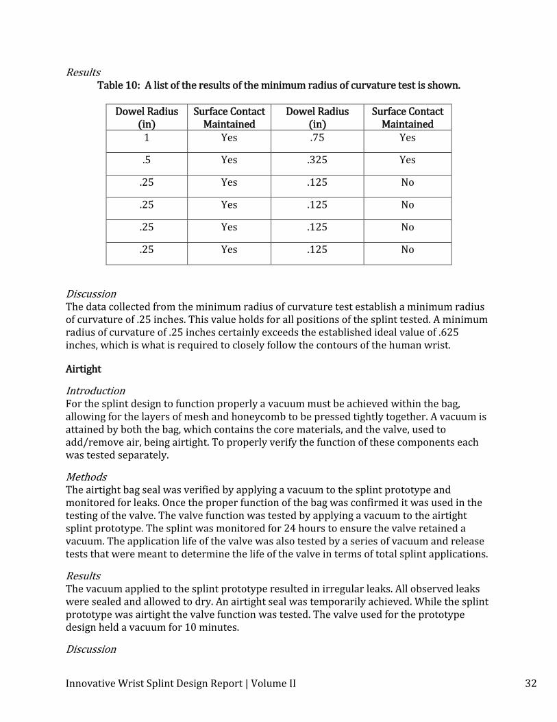
Results Table 10: A list of the results of the minimum radius of curvature test is shown.
Dowel Radius
(in) Surface Contact
Maintained Dowel Radius
(in) Surface Contact
Maintained 1 Yes .75 Yes
.5 Yes .325 Yes
.25 Yes .125 No
.25 Yes .125 No
.25 Yes .125 No
.25 Yes .125 No
Discussion The data collected from the minimum radius of curvature test establish a minimum radius of curvature of .25 inches. This value holds for all positions of the splint tested. A minimum radius of curvature of .25 inches certainly exceeds the established ideal value of .625 inches, which is what is required to closely follow the contours of the human wrist.
Airtight
Introduction For the splint design to function properly a vacuum must be achieved within the bag, allowing for the layers of mesh and honeycomb to be pressed tightly together. A vacuum is attained by both the bag, which contains the core materials, and the valve, used to add/remove air, being airtight. To properly verify the function of these components each was tested separately.
Methods The airtight bag seal was verified by applying a vacuum to the splint prototype and monitored for leaks. Once the proper function of the bag was confirmed it was used in the testing of the valve. The valve function was tested by applying a vacuum to the airtight splint prototype. The splint was monitored for 24 hours to ensure the valve retained a vacuum. The application life of the valve was also tested by a series of vacuum and release tests that were meant to determine the life of the valve in terms of total splint applications.
Results The vacuum applied to the splint prototype resulted in irregular leaks. All observed leaks were sealed and allowed to dry. An airtight seal was temporarily achieved. While the splint prototype was airtight the valve function was tested. The valve used for the prototype design held a vacuum for 10 minutes.
Discussion
Innovative Wrist Splint Design Report | Volume II 33
The observations made will verifying the airtight bag and valve exhibit the need for further design refinement. Although an airtight bag seal was achieved, due to deficiencies in the material adhesive used a permanent seal was not realized. The valve tested was used for rough prototyping and failed to meet the design requirement of permanently holding a vacuum. The failure of the valve was attributed to the connection between made with the tubing.
Weight
Introduction The splint should be lightweight so the patient will be able to function with the fractured limb. Moreover, the patient should be able to move their arm without feeling labored.
Methods A scale was used to determine the weight of the splint. The scale used was a Virtual Measurements Control VB302. A known mass was placed on the scale to determine the accuracy of the scale. The scale was zeroed and the splint was placed on it. The test was repeated five times.
Results
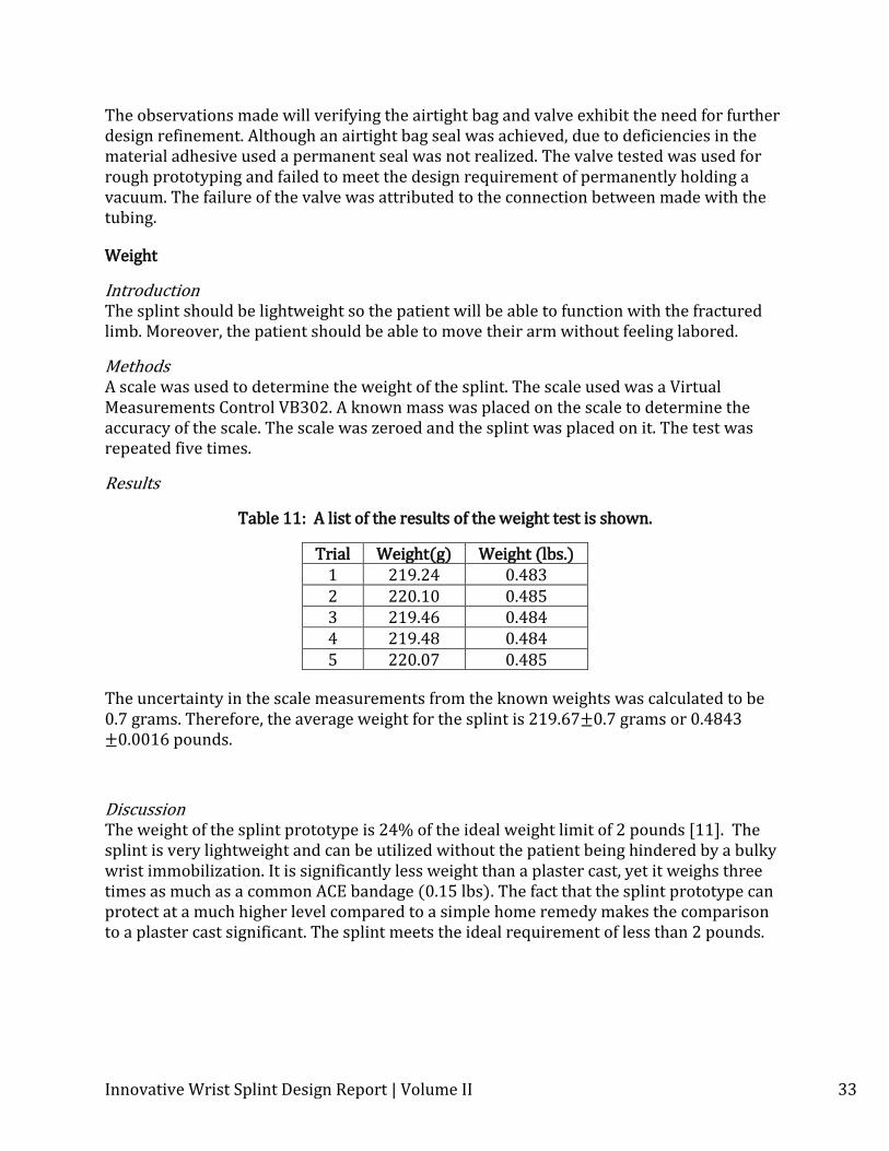
Table 11: A list of the results of the weight test is shown.
Trial Weight(g) Weight (lbs.) 1 219.24 0.483 2 220.10 0.485 3 219.46 0.484 4 219.48 0.484 5 220.07 0.485
The uncertainty in the scale measurements from the known weights was calculated to be 0.7 grams. Therefore, the average weight for the splint is 219.67±0.7 grams or 0.4843 ±0.0016 pounds.
Discussion The weight of the splint prototype is 24% of the ideal weight limit of 2 pounds [11]. The splint is very lightweight and can be utilized without the patient being hindered by a bulky wrist immobilization. It is significantly less weight than a plaster cast, yet it weighs three times as much as a common ACE bandage (0.15 lbs). The fact that the splint prototype can protect at a much higher level compared to a simple home remedy makes the comparison to a plaster cast significant. The splint meets the ideal requirement of less than 2 pounds.
Innovative Wrist Splint Design Report | Volume II 34
Application
Introduction The application time and ease of use are essential for professionals to utilize the splint effectively. The professionals can see more patients over the course of the day and the efficacy of each application will not be compromised. Medical professionals are familiar to the protection needs of a splint and the application process that needs to be followed when utilizing one.
Methods Medical professionals and University of Minnesota students employed as Emergency Medical Technicians were observed as they applied the splint with minimal prior knowledge/training as to how it works. Feedback was documented and the application time from multiple attempts was averaged.
Professional #1: Ben Cooper: Field Training Officer U of M EMS Professional #2: Abhayjit Singh: Rochester EMT Services
The professionals performed the tests individually. Each was presented with information about the splint and shown how to apply the prototype. Next, each person was allowed to apply the splint on their arm once to get a feel for the process. The testing was performed on the arm of the same group member each trial and no assistance was given to the subject as they applied the splint. The times reflect the forming of the splint only – the vacuum aspect of the application process adds the same amount of time for the splint with a fixed volume so it was not tested. Feedback for the application process was requested at the end of each professional test.
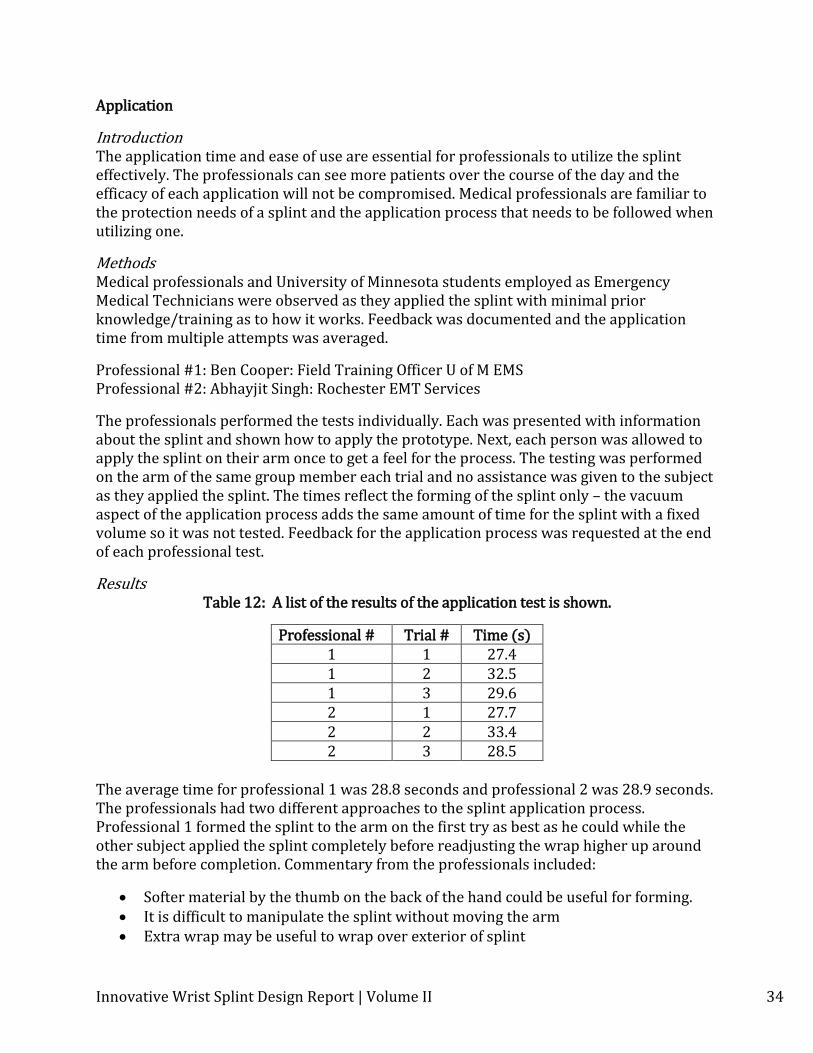
Results Table 12: A list of the results of the application test is shown.
Professional # Trial # Time (s) 1 1 27.4 1 2 32.5 1 3 29.6 2 1 27.7 2 2 33.4 2 3 28.5
The average time for professional 1 was 28.8 seconds and professional 2 was 28.9 seconds. The professionals had two different approaches to the splint application process. Professional 1 formed the splint to the arm on the first try as best as he could while the other subject applied the splint completely before readjusting the wrap higher up around the arm before completion. Commentary from the professionals included:
Softer material by the thumb on the back of the hand could be useful for forming. It is difficult to manipulate the splint without moving the arm Extra wrap may be useful to wrap over exterior of splint
Innovative Wrist Splint Design Report | Volume II 35
An EMT applying a splint takes a minimum of 30 seconds to a maximum of 90 seconds.
Mechanical pumps might be useful for field operations Discussion
The average time for a professional to form the splint was only 30 seconds. There also could be application of a surgical sleeve or cotton wrap to the skin before the splint is applied which could add 1-2 minutes. Furthermore, the vacuum time for the splint prototype is about 15 seconds. The final application time can be calculated to be 1-3 minutes. This application time is 90% less than a plaster cast (30 minutes) and much less than the 10 minute ideal specification, so the test succeeded.
Compressive Load
Introduction
The objective of this test is to determine the compressive load strength of the splint
prototype. The ability of the splint to withstand compressive loads is important to
maintaining limb immobilization for proper healing of the bone.
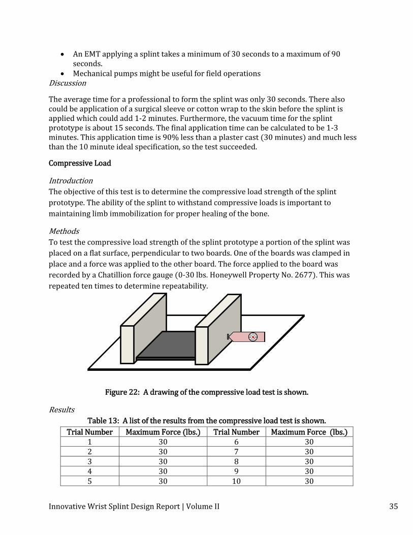
Methods
To test the compressive load strength of the splint prototype a portion of the splint was
placed on a flat surface, perpendicular to two boards. One of the boards was clamped in
place and a force was applied to the other board. The force applied to the board was
recorded by a Chatillion force gauge (0-30 lbs. Honeywell Property No. 2677). This was
repeated ten times to determine repeatability.
Figure 22: A drawing of the compressive load test is shown.
Results
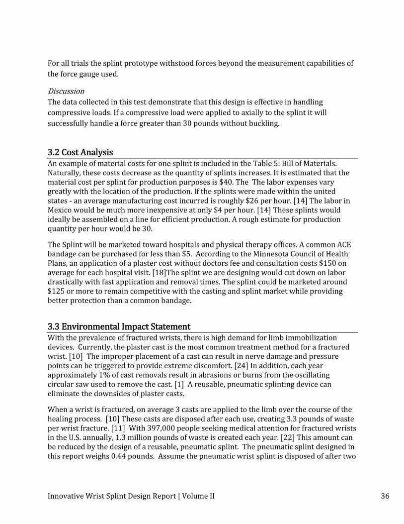
Table 13: A list of the results from the compressive load test is shown.
Trial Number Maximum Force (lbs.) Trial Number Maximum Force (lbs.) 1 30 6 30 2 30 7 30 3 30 8 30 4 30 9 30 5 30 10 30
Innovative Wrist Splint Design Report | Volume II 36
For all trials the splint prototype withstood forces beyond the measurement capabilities of
the force gauge used.
Discussion
The data collected in this test demonstrate that this design is effective in handling
compressive loads. If a compressive load were applied to axially to the splint it will
successfully handle a force greater than 30 pounds without buckling.
3.2 Cost Analysis An example of material costs for one splint is included in the Table 5: Bill of Materials. Naturally, these costs decrease as the quantity of splints increases. It is estimated that the material cost per splint for production purposes is $40. The The labor expenses vary greatly with the location of the production. If the splints were made within the united states - an average manufacturing cost incurred is roughly $26 per hour. [14] The labor in Mexico would be much more inexpensive at only $4 per hour. [14] These splints would ideally be assembled on a line for efficient production. A rough estimate for production quantity per hour would be 30.
The Splint will be marketed toward hospitals and physical therapy offices. A common ACE bandage can be purchased for less than $5. According to the Minnesota Council of Health Plans, an application of a plaster cost without doctors fee and consultation costs $150 on average for each hospital visit. [18]The splint we are designing would cut down on labor drastically with fast application and removal times. The splint could be marketed around $125 or more to remain competitive with the casting and splint market while providing better protection than a common bandage.
3.3 Environmental Impact Statement With the prevalence of fractured wrists, there is high demand for limb immobilization devices. Currently, the plaster cast is the most common treatment method for a fractured wrist. [10] The improper placement of a cast can result in nerve damage and pressure points can be triggered to provide extreme discomfort. [24] In addition, each year approximately 1% of cast removals result in abrasions or burns from the oscillating circular saw used to remove the cast. [1] A reusable, pneumatic splinting device can eliminate the downsides of plaster casts.
When a wrist is fractured, on average 3 casts are applied to the limb over the course of the healing process. [10] These casts are disposed after each use, creating 3.3 pounds of waste per wrist fracture. [11] With 397,000 people seeking medical attention for fractured wrists in the U.S. annually, 1.3 million pounds of waste is created each year. [22] This amount can be reduced by the design of a reusable, pneumatic splint. The pneumatic splint designed in this report weighs 0.44 pounds. Assume the pneumatic wrist splint is disposed of after two
Innovative Wrist Splint Design Report | Volume II 37
fracture treatments. By replacing just half of casts with the reusable splint, the amount of waste created from wrist fractures decreases to 700,000 pounds of waste annually.
The innovative splint is manufactured using a straightforward procedure. Minimal excess waste will be created during manufacturing by following a pattern for the honeycomb, mesh, and bag material. The materials required are commercially produced products, with no abnormal or notable impact to the environment. The vacuum pump used in the application of the product will consume a relatively small amount of power throughout the lifetime of the splint.
The use of this splint is not limited to one fracture. Patients and families are able to keep the splint for future injuries. With the bandage wrap design, the splint is not custom made for any one patient. This presents the opportunity for a reuse program. Patients could have the ability to donate their splint to a hospital or other organization, so that it may be used by future patients. Another option that would increase the impact of a single splint is to have hospital or other institutions purchase the splint rather than individual patients. The patient would then return the splint to the hospital after treatment is completed, and the splint would be used in future treatments.
Reusability was an important factor in the design of the pneumatic splinting device. While end of life reclamation programs could impact how many splints are sold, the price of manufacturing the splint will not be directly impacted. This can be accounted for by correlating the price of the splint with the average lifetime of the product.
3.4 Regulatory and Safety Considerations The U.S. Food and Drug Administration regulates many different types of products besides food and drugs including medical devices. All medical devices are listed as a Class I, II, or III device. Many Class I and some II devices are exempt from having to file a 510(k) Premarket Notification. According to the FDA website, many orthopedic devices are exempt. In order to be exempt, a Class I or select Class II device must also meet the criteria as shown below from the Food and Drug Administration:
For purposes of 510(k) decision-making, the term "preamendment device" refers to devices legally marketed in the U.S. by a firm before May 28, 1976 and which have not been:
significantly changed or modified since then; and for which a regulation requiring a PMA application has not been published by FDA. [19]
As the device is orthopedic, and has a similar device on the market, such as the SAM Splint, the device is likely exempt from having to file a 510(k). The splint still must be registered with the FDA as the SAM Splint. [23]
Innovative Wrist Splint Design Report | Volume II 38
The company that actually makes the splint also must be registered with the FDA and pay a yearly fee to be able to sell the splint.
As with nearly all medical devices, it will be important that the splint be applied correctly and by professionals in the health care field. It is a pneumatic device requiring a vacuum pump, which is different than many current splints. This means that for the safety of the patient, a large amount of training will need to be done with these health care professionals by the company that produces the splint. The splint may not be completely comparable to a cast in terms of stiffness, so advising doctors in the correct types of fractures and sprains the splint will excel in protecting will be important with regard to patient safety also.
4. List of Figures and Tables Figure 1: Drawing representing a current plaster cast. Figure 2: Drawings of concepts that use a pneumatic sandwich structure Figure3: Drawings of concepts that use a pneumatic interlocking geometry. Figure 4: Drawing of the pneumatic particle concept. Figure 5: Drawing of the thermoplastic concept. Figure 6: Drawing of the innovative splint design applied to an arm. Figure 7: Drawing of the splint before application. Figure 8: Drawing of the splint around the palm. Figure 9: Drawing of the thumb hole in the splint. Figure 10: Schematic of the bidirectional flow valve. Figure 11: Drawing of the exploded view of the splint design. Figure 12: Dimensional drawing of the material pattern used. Figure 13: Drawing of the material failure testing procedure. Figure 14: Drawing of the impact resistance testing procedure. Figure 15: Diagram of the setup used in testing stiffness. Figure 16: Graph of splint modulus of elasticity vs. force applied. Figure 17: Graph of deflection data vs. force applied. Figure 18: Drawing depicting shear and bending deflection. Figure 19: Drawing of the honeycomb dimensions. Figure 20: Graph of En vs. applied force. Figure 21: Drawing of the procedure followed in radius of curvature testing. Figure 22: Drawing of the compressive load test setup. Table 1: List of customer needs for a splint. Table 2: List of concept selection criteria and there description. Table 3: Concept selection matrix. Table 4. Concept scoring matrix. Table 5. Splint bill of materials. Table 6. Accessories bill of materials. Table 7: List of the material failure test results. Table 8: List of the impact resistance test results.

Innovative Wrist Splint Design Report | Volume II 39
Table 9: List of modulus results from the stiffness test. Table 10: List of the results of the minimum radius of curvature test. Table 11: List of the results of the weight test. Table 12: List of the results of the application test. Table 13: List of the results from the compressive load test.
5. Appendix
Innovative Wrist Splint Design Report | Volume II 40
5.1 Patent First Pages
Vacuum Splint Device | David A. Daugherty et al

Innovative Wrist Splint Design Report | Volume II 41
Orthopaedic Splint | Michael Degun, Lain Andrew, Craig Lennox
Innovative Wrist Splint Design Report | Volume II 42
Orthopedic System for Immobilizing and Supporting Body Parts | Mark Joseph
Innovative Wrist Splint Design Report | Volume II 43
Integrated synergistic emergency splint | Alan F. Marble
Innovative Wrist Splint Design Report | Volume II 44
Methods and apparatus for stabilizing tissue | Gary S. Kochamba et al
Innovative Wrist Splint Design Report | Volume II 45
5.2 Custumer Needs Supporting Documents
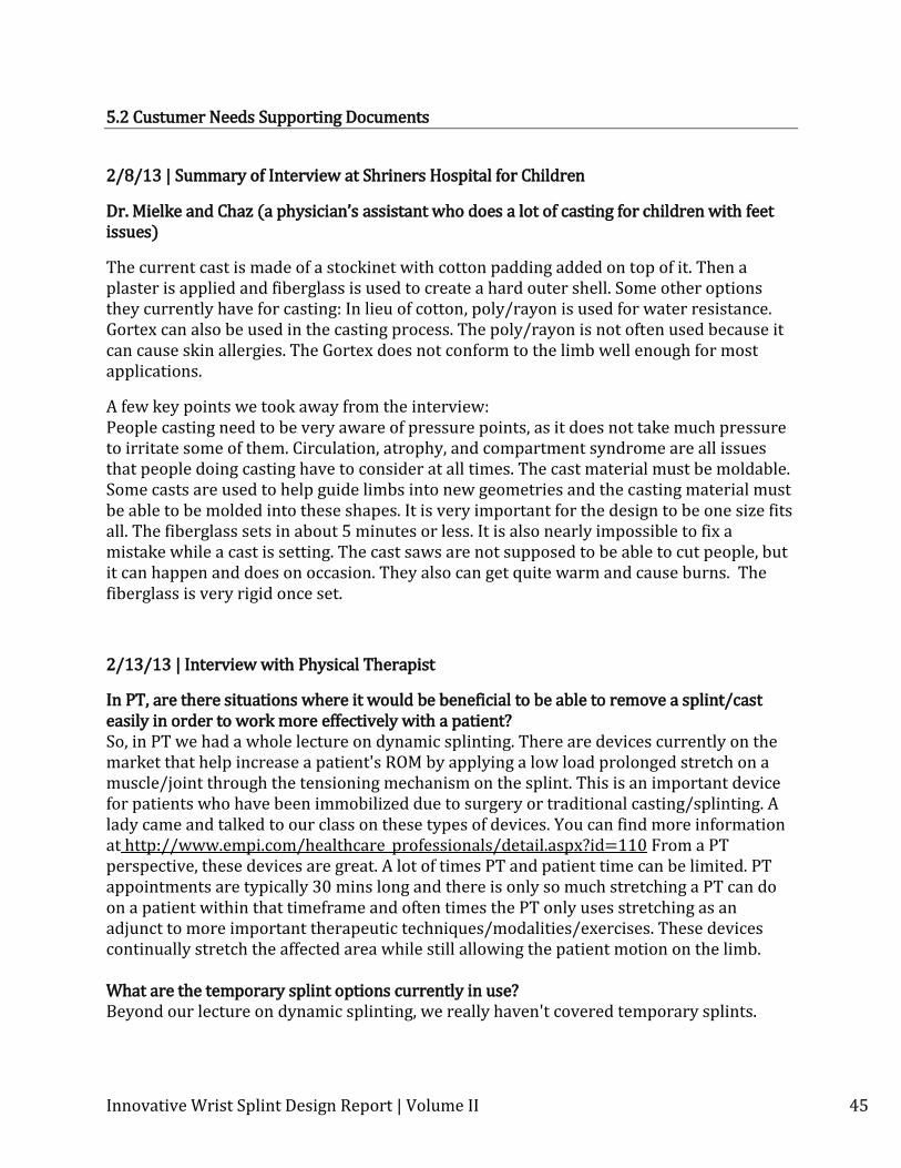
2/8/13 | Summary of Interview at Shriners Hospital for Children
Dr. Mielke and Chaz (a physician’s assistant who does a lot of casting for children with feet issues)
The current cast is made of a stockinet with cotton padding added on top of it. Then a plaster is applied and fiberglass is used to create a hard outer shell. Some other options they currently have for casting: In lieu of cotton, poly/rayon is used for water resistance. Gortex can also be used in the casting process. The poly/rayon is not often used because it can cause skin allergies. The Gortex does not conform to the limb well enough for most applications.
A few key points we took away from the interview: People casting need to be very aware of pressure points, as it does not take much pressure to irritate some of them. Circulation, atrophy, and compartment syndrome are all issues that people doing casting have to consider at all times. The cast material must be moldable. Some casts are used to help guide limbs into new geometries and the casting material must be able to be molded into these shapes. It is very important for the design to be one size fits all. The fiberglass sets in about 5 minutes or less. It is also nearly impossible to fix a mistake while a cast is setting. The cast saws are not supposed to be able to cut people, but it can happen and does on occasion. They also can get quite warm and cause burns. The fiberglass is very rigid once set.
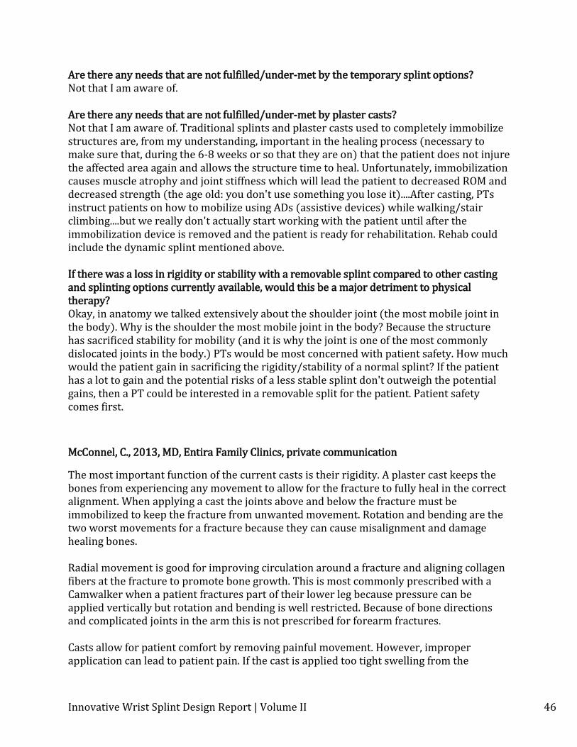
2/13/13 | Interview with Physical Therapist
In PT, are there situations where it would be beneficial to be able to remove a splint/cast easily in order to work more effectively with a patient? So, in PT we had a whole lecture on dynamic splinting. There are devices currently on the market that help increase a patient's ROM by applying a low load prolonged stretch on a muscle/joint through the tensioning mechanism on the splint. This is an important device for patients who have been immobilized due to surgery or traditional casting/splinting. A lady came and talked to our class on these types of devices. You can find more information at http://www.empi.com/healthcare_professionals/detail.aspx?id=110 From a PT perspective, these devices are great. A lot of times PT and patient time can be limited. PT appointments are typically 30 mins long and there is only so much stretching a PT can do on a patient within that timeframe and often times the PT only uses stretching as an adjunct to more important therapeutic techniques/modalities/exercises. These devices continually stretch the affected area while still allowing the patient motion on the limb. What are the temporary splint options currently in use? Beyond our lecture on dynamic splinting, we really haven't covered temporary splints.
Innovative Wrist Splint Design Report | Volume II 46
Are there any needs that are not fulfilled/under-met by the temporary splint options? Not that I am aware of. Are there any needs that are not fulfilled/under-met by plaster casts? Not that I am aware of. Traditional splints and plaster casts used to completely immobilize structures are, from my understanding, important in the healing process (necessary to make sure that, during the 6-8 weeks or so that they are on) that the patient does not injure the affected area again and allows the structure time to heal. Unfortunately, immobilization causes muscle atrophy and joint stiffness which will lead the patient to decreased ROM and decreased strength (the age old: you don't use something you lose it)....After casting, PTs instruct patients on how to mobilize using ADs (assistive devices) while walking/stair climbing....but we really don't actually start working with the patient until after the immobilization device is removed and the patient is ready for rehabilitation. Rehab could include the dynamic splint mentioned above. If there was a loss in rigidity or stability with a removable splint compared to other casting and splinting options currently available, would this be a major detriment to physical therapy? Okay, in anatomy we talked extensively about the shoulder joint (the most mobile joint in the body). Why is the shoulder the most mobile joint in the body? Because the structure has sacrificed stability for mobility (and it is why the joint is one of the most commonly dislocated joints in the body.) PTs would be most concerned with patient safety. How much would the patient gain in sacrificing the rigidity/stability of a normal splint? If the patient has a lot to gain and the potential risks of a less stable splint don't outweigh the potential gains, then a PT could be interested in a removable split for the patient. Patient safety comes first.
McConnel, C., 2013, MD, Entira Family Clinics, private communication
The most important function of the current casts is their rigidity. A plaster cast keeps the bones from experiencing any movement to allow for the fracture to fully heal in the correct alignment. When applying a cast the joints above and below the fracture must be immobilized to keep the fracture from unwanted movement. Rotation and bending are the two worst movements for a fracture because they can cause misalignment and damage healing bones. Radial movement is good for improving circulation around a fracture and aligning collagen fibers at the fracture to promote bone growth. This is most commonly prescribed with a Camwalker when a patient fractures part of their lower leg because pressure can be applied vertically but rotation and bending is well restricted. Because of bone directions and complicated joints in the arm this is not prescribed for forearm fractures. Casts allow for patient comfort by removing painful movement. However, improper application can lead to patient pain. If the cast is applied too tight swelling from the

Innovative Wrist Splint Design Report | Volume II 47
fracture can press against the cast and cause pain. Also, if padding is not properly applied the edges of the cast can be sharp and press into a patient’s skin causing irritation.