Innovative New Live Line Tool and Framing Designs ... · Innovative New Live Line Tool and Framing...
24
Innovative New Live Line Tool and Framing Designs Facilitating Safe and Efficient Cross-arm Replacement A.J. Carreira, P.Eng., SMIEEE President K-LINE INSULATORS LIMITED Toronto, Canada [email protected]
Transcript of Innovative New Live Line Tool and Framing Designs ... · Innovative New Live Line Tool and Framing...
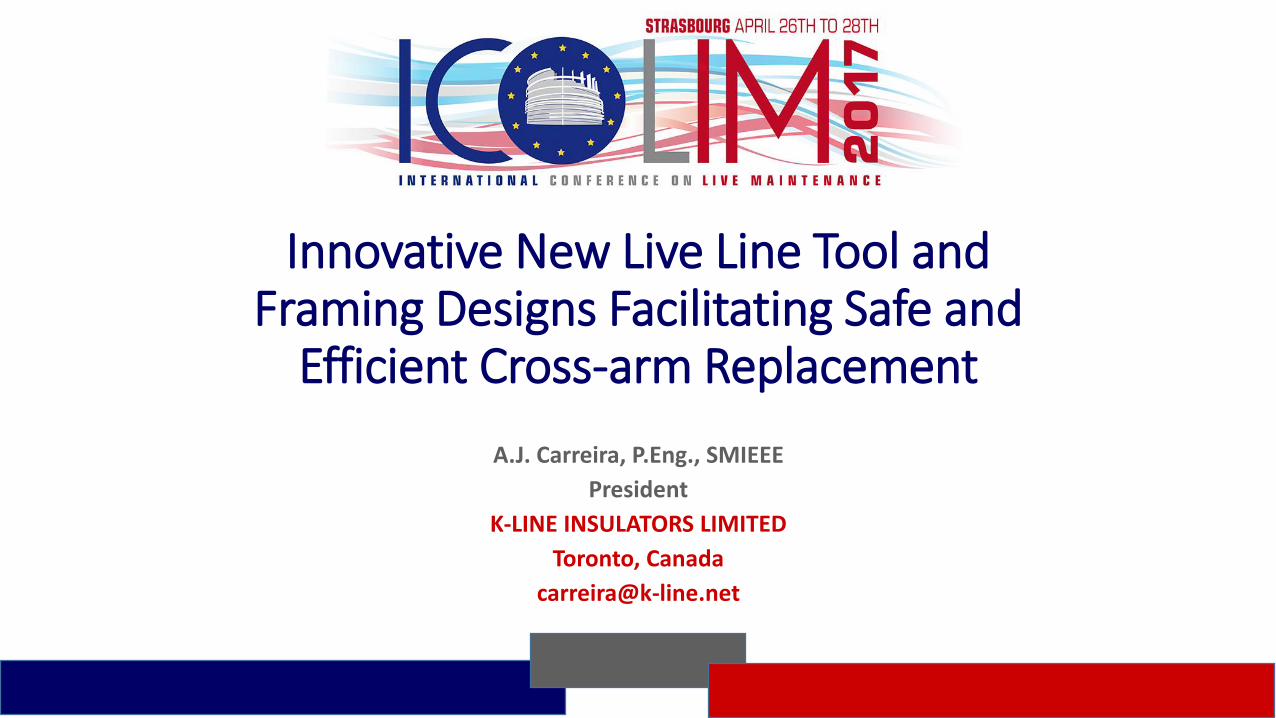
Innovative New Live Line Tool andFraming Designs Facilitating Safe and
Efficient Cross-arm Replacement
A.J. Carreira, P.Eng., SMIEEE
President
K-LINE INSULATORS LIMITED
Toronto, Canada

K-LINE INSULATORS LIMITED
ISSUES WITH CURRENT CROSS ARM FRAMINGS:- Limited life of wood crossarms (mainly due to rot)
- Steel crossarms susceptible to corrosion
- Fiber reinforced polymer (FRP) crossarms susceptible to surface tracking and degradation
Internal Rot
Steel Arm Corrosion
Rot
FRP DegradationInternal Rot
FRP Surface Tracking

K-LINE INSULATORS LIMITED
Demand for power increasing
Capacities of power systems pushed to their limits
Removing lines from service becoming ever increasing challenge

K-LINE INSULATORS LIMITED
The “Issues” With Existing Live Line Work Tools
Courtesy of Hydro One
Rigging equipment mechanical ratings typically require a 5 to 1 safety factor
At high loads:• Conventional Hot Line Tool Auxiliary Arm configurations for Live Line Work (LLW) can become “strained”• Pole attachments and saddles can dig into the pole & create damage
Other issues when using conventional live line tool auxilary arms include:- Setup is time consuming- Inclement weather requires removal and shutdown of the operation- Higher load capabilities rigging arrangements are required
- For longer spans- Larger conductor sizes- Combination of longer spans & larger conductors
NEW LLW EQUIPMENT IS REQUIRED TO ADDRESS THE ABOVE ISSUES

K-LINE INSULATORS LIMITED
There exists an obvious need to design new:
Tools Equipment Materials, and Work Methods
to facilitate live line cross-arm replacements.

K-LINE INSULATORS LIMITED
K-ARMTM
Auxiliary Arm
Tool designed using modular components for:
Improved installation
Transportation
Other key features of these new tool designs include:
Brace support insulators which can be used in high load applications
Offering higher working load limits (WLL)
Lightweight Aluminum Base bolts or straps directly to pole
Improved conductor support stability and performance
Silicone rubber insulators used in these designs
Eliminates issues and concerns related to inclement weather
In some designs, the K-ARMTM tool incorporates the very popular K-CLAMP®
Easily and Safely facilitates live line tool work methods
Accommodates conductor sizes ranging from #4 AWG to 1192 kcmil
(or about 6 mm diameter conductor to 34mm diameter conductor)
Live Line Tool Designs for 115 kV & 230 kV Power Lines

K-LINE INSULATORS LIMITED
115 kV Auxiliary ArmConductor Moved to
K-CLAMP®
Conductor Secured in Position Using
Grip-All Clamp Stick
Conductor Temporarily Supported
by K-ARMTM

K-LINE INSULATORS LIMITED
K-ARMTM
Auxiliary Arm with & without Brace Support
230 kV 115 kV
K-LINE INSULATORS LIMITED
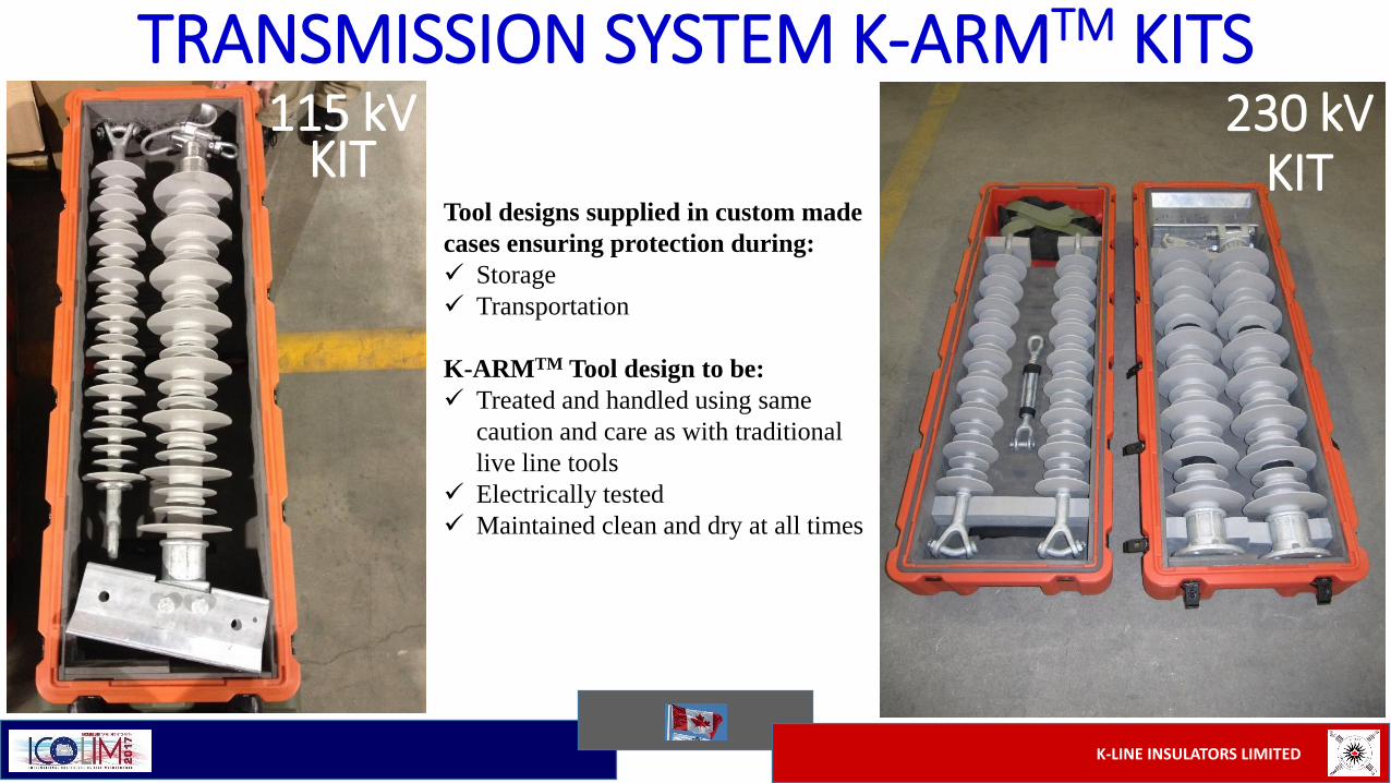
TRANSMISSION SYSTEM K-ARMTM KITS230 kV
KIT115 kV
KITTool designs supplied in custom made
cases ensuring protection during:
Storage
Transportation
K-ARMTM Tool design to be:
Treated and handled using same
caution and care as with traditional
live line tools
Electrically tested
Maintained clean and dry at all times
K-LINE INSULATORS LIMITED
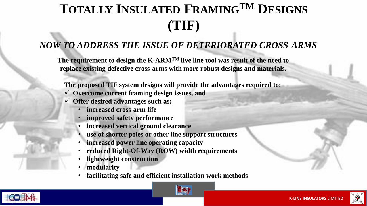
NOW TO ADDRESS THE ISSUE OF DETERIORATED CROSS-ARMS
TOTALLY INSULATED FRAMINGTM DESIGNS
(TIF)
The proposed TIF system designs will provide the advantages required to:
Overcome current framing design issues, and
Offer desired advantages such as:
• increased cross-arm life
• improved safety performance
• increased vertical ground clearance
• use of shorter poles or other line support structures
• increased power line operating capacity
• reduced Right-Of-Way (ROW) width requirements
• lightweight construction
• modularity
• facilitating safe and efficient installation work methods
The requirement to design the K-ARMTM live line tool was result of the need to
replace existing defective cross-arms with more robust designs and materials.

K-LINE INSULATORS LIMITED
TOTALLY INSULATED FRAMINGS(patent pending)
H-Frame Structure TIFThree Phase Single
Circuit Structure TIF
New TIF Designs combine insulators assembled
together in innovative new configurations to
perform both the:
Line Insulation Function of the Structure, and
Mechanical cross-arm function of the Structure
Typical existing cross-arm designs illustrated in
shadow form.
New replacement TIF designs superimposed.

K-LINE INSULATORS LIMITED
TIF Tri-Frame Field TrialLightweight
characterisitics
of the TIF
designs
Factory
assembled
in one piece
TIF designs offer opportunity for large cost
savings over conventional cross-arm line
designs, including a major decrease in labour:
No assembly
Reduced set up time
Six (6) minute installation time
TIF Designs
Permit use of
Conventional
Stringing
Equipment

K-LINE INSULATORS LIMITED
Major Canadian Utility Installation in Kleinberg, Ontario
TIF designs offer opportunity for large cost
savings over conventional cross-arm line
designs, including a major decrease in labour:
No assembly
Reduced set up time
Twenty Six (26) minute installation time
K-LINE INSULATORS LIMITED
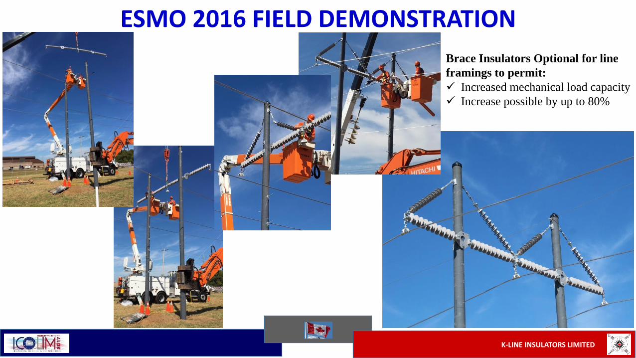
ESMO 2016 FIELD DEMONSTRATION
Brace Insulators Optional for line
framings to permit:
Increased mechanical load capacity
Increase possible by up to 80%
K-LINE INSULATORS LIMITED
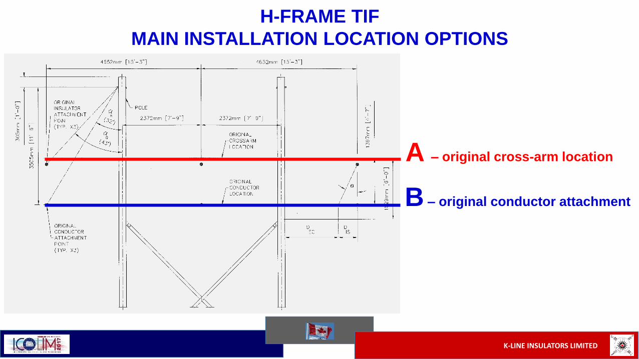
H-FRAME TIF
MAIN INSTALLATION LOCATION OPTIONS
A – original cross-arm location
B – original conductor attachment
K-LINE INSULATORS LIMITED
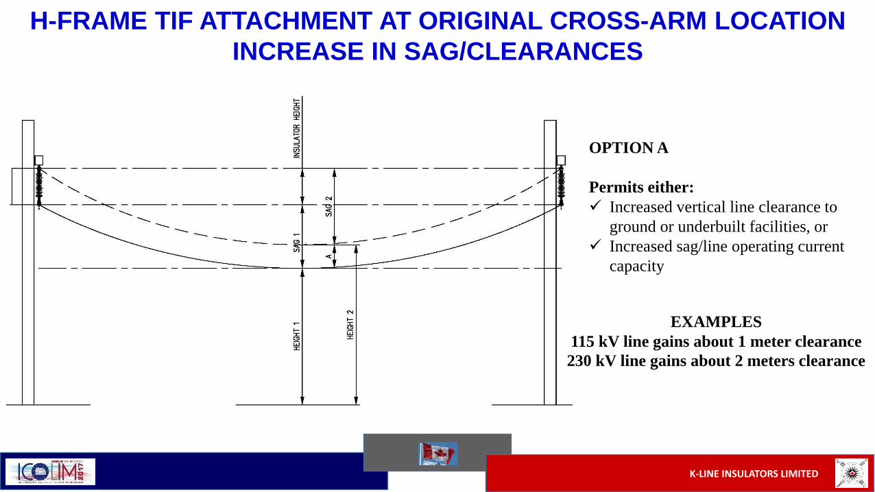
H-FRAME TIF ATTACHMENT AT ORIGINAL CROSS-ARM LOCATION
INCREASE IN SAG/CLEARANCES
OPTION A
Permits either:
Increased vertical line clearance to
ground or underbuilt facilities, or
Increased sag/line operating current
capacity
EXAMPLES
115 kV line gains about 1 meter clearance
230 kV line gains about 2 meters clearance
K-LINE INSULATORS LIMITED
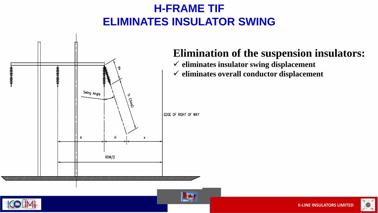
H-FRAME TIF
ELIMINATES INSULATOR SWING
Elimination of the suspension insulators: eliminates insulator swing displacement
eliminates overall conductor displacement

K-LINE INSULATORS LIMITED
H-FRAME TIFOPTION A – ORIGINAL CROSS-ARM ELEVATION
ADVANTAGES- Eliminates need for suspension insulator
+ permits increase in line sag
+ permits increase in line ampacity
+ permits increase in ground and/or underbuild clearances
LIGHTNING PROTECTION ANGLE (α):- Effectiveness depends on:
+ line height
+ fault current amplitudes
+ existing shield angle
- Improved lightning protection angle with reduced phase spacing
- Eliminates insulator swing distance (DIS)
+ eliminates insulator swing angle (θ)
+ permits reduced phase spacing
+ maintains electrical clearance distance to structure (DEC)
+ reduces necessary ROW width
- Fosters lower cost framing design
+ permits shorter TIF cross-arm lengths
K-LINE INSULATORS LIMITED
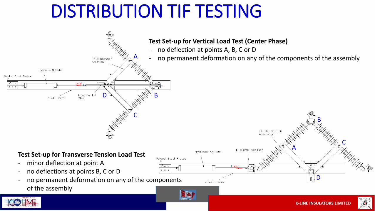
DISTRIBUTION TIF TESTING
Test Set-up for Transverse Tension Load Test- minor deflection at point A- no deflections at points B, C or D- no permanent deformation on any of the components
of the assembly
Test Set-up for Vertical Load Test (Center Phase)- no deflection at points A, B, C or D- no permanent deformation on any of the components of the assembly
AC
B
D
A
BC
D
K-LINE INSULATORS LIMITED
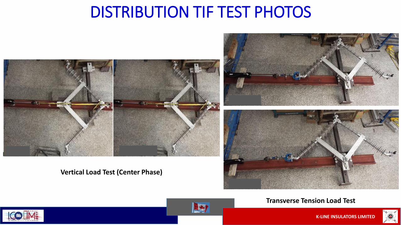
DISTRIBUTION TIF TEST PHOTOS
Transverse Tension Load Test
Vertical Load Test (Center Phase)
K-LINE INSULATORS LIMITED
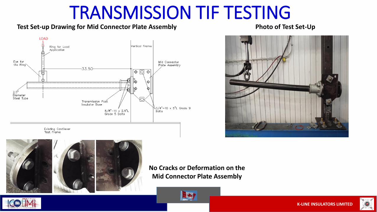
TRANSMISSION TIF TESTINGTest Set-up Drawing for Mid Connector Plate Assembly Photo of Test Set-Up
No Cracks or Deformation on the Mid Connector Plate Assembly

K-LINE INSULATORS LIMITED
Transmission TIF Cross-arm Designs can be: delivered in modular components, or
delivered factory-assembled as a one-piece system
if necessary, components can be easily replaced in situ and normally without removing the complete arm
installed with simplicity and safely hoisted to position & quickly bolted to the structure with two machine bolts per pole
installation time is minimized, thereby minimizing field personnel hazard exposure
easily be customized to the various framing arrangements and line voltages
installation cost is minimized

K-LINE INSULATORS LIMITED
TOTALLY INSULATED FRAMINGS
SUMMARY OF ADVANTAGES
- Eliminate all current cross-arm material deterioration issues
- Increase structure framing life expectancy
- Improve line safety
- Are easy to transport
- Increase ground and underbuild clearances
- Increase power line operating currents
- Require use of shorter pole or other structures
- Require reduced right-of-way (ROW) widths
- Are Modular and easy to transport
- Are Lightweight and easy to erect without heavy equipment or helicopters
- Can be customized to any structure and conductor spacing
- Are integrated line insulation solutions eliminating requirement for any additional insulators
- Can be used on new construction
- Can be used to retrofit existing conventional cross-arm line framing designs
- Protect wildlife and discourages bird nesting
- Avoid vandalism associated with glass and porcelain insulators
- Distribution & Transmission three phase line designs available

K-LINE INSULATORS LIMITED
CONCLUSIONS
Need to replace existing deteriorating cross-arms is a growing issue.
Need to develop new, safer and more efficient tools
Utilities deal with the constant need to maintain dependable and uninterrupted power
supply to Customers
Live line work methods are the preferred approach when conducting most maintenance
work activities today
New tools, equipment and materials presented offer new opportunities for field personnel to
meet these challenging maintnenance and system performance requirements:
- Effectively
- Safely
- Cost effectively