Innovative Design of Linkage- Counterweight Ferry Transfer ...
15
HEAVY MOVABLE STRUCTURES, INC. TENTH BIENNIAL SYMPOSIUM OCTOBER 25 - 28, 2004 The Omni Orlando Resort at ChampionsGate Innovative Design of Linkage- Counterweight Ferry Transfer Span System Greg Oliver Chris Rolfson Hartford Engineering, LLC Machinery/Mechanics Paper No. 30
Transcript of Innovative Design of Linkage- Counterweight Ferry Transfer ...

HEAVY MOVABLE STRUCTURES, INC.
TENTH BIENNIAL SYMPOSIUM
OCTOBER 25 - 28, 2004The Omni Orlando Resort at ChampionsGate
Innovative Design of Linkage-Counterweight Ferry Transfer Span System
Greg OliverChris Rolfson
Hartford Engineering, LLC
Machinery/Mechanics
Paper No. 30

Low-Maintenance Transfer Span System
2
Innovative Design of Linkage-Counterweight Ferry Transfer Span System Introduction
Project Background
The State of Texas Department of Transportation (TxDOT) operates a popular vehicle and passenger ferry service between Galveston Island and the Bolivar Pennisula. Located approximately 50 miles from downtown Houston, the two existing ferry landings at each terminus were not adequate to meet the route’s growing demands. Our firm, in conjunction with CH2M Hill, was contacted by TxDOT to design a new ferry loading system to expand the existing loading systems on Galveston Bay. This project was to add a third slip, of new design, at each terminus. TxDOT’s primary concerns were to reduce unanticipated down-time, keep installation and on-going maintenance costs to a minimum, and to simplify the installation and commissioning of the new system. With these goals in mind, and wanting to incorporate some of the most recent advances in materials and processing technology, we set about designing a system that would be unmatched in reliable, low-maintenance service. This paper describes some of our designs and the considerations that guided our process. We will break the new systems design into the following categories for consideration:
� Simplifying Designs- what systems could good design greatly simplify? � Cost Reduction- how can a new design provide outstanding value for our clients?
� Safety Improvements- utilize innovative safety improvements throughout the design.
� Ease of Maintenance- utilize advanced bearing materials and processes for corrosion protection.
Low-Maintenance Transfer Span System
3
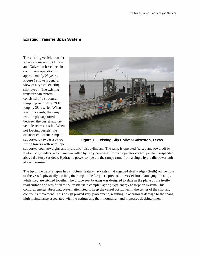
Existing Transfer Span System The existing vehicle transfer span systems used at Bolivar and Galveston have been in continuous operation for approximately 28 years. Figure 1 shows a general view of a typical existing slip layout. The existing transfer span system consisted of a structural ramp approximately 29 ft long by 28 ft wide. When loading vessels, the ramp was simply supported between the vessel and the vehicle access trestle. When not loading vessels, the offshore end of the ramp is supported by two truss-type lifting towers with wire-rope supported counterweights and hydraulic hoist cylinders. The ramp is operated (raised and lowered) by hydraulic cylinders, which are controlled by ferry personnel from an operator control pendant suspended above the ferry car deck. Hydraulic power to operate the ramps came from a single hydraulic power unit at each terminal. The tip of the transfer span had structural features (sockets) that engaged steel wedges (teeth) on the nose of the vessel, physically latching the ramp to the ferry. To prevent the vessel from damaging the ramp, while they are latched together, the bridge seat bearing was designed to slide in the plane of the trestle road surface and was fixed to the trestle via a complex spring-type energy absorption system. This complex energy-absorbing system attempted to keep the vessel positioned in the center of the slip, and control its movement. This design proved very problematic, resulting in occasional damage to the spans, high maintenance associated with the springs and their mountings, and increased docking times.
Figure 1: Existing Slip.
Figure 1. Existing Slip Bolivar-Galveston, Texas.

Low-Maintenance Transfer Span System
4
Simplifying Designs- Design Approach Our group first identified our customer’s priorities, by interviewing those involved with the maintenance and operation of the existing system. From this we identified a list of shortcomings to prioritize as design goals.
� The existing ramp latches to the vessel during loading operations. The process of latching the ramp to the ferry deck is problematic, requiring the operator to time the descent of the ramp such that it meets the vessel when the roll of the vessel is compatible with the ramp. This operation is not optimal for vessel operations in that the latching process can take significant time and exposes the ramp to damage from colliding with the vessel during the latching operation. Once the ramp is latched, it is exposed to significant loads from the vessel, requiring the incorporation of a large and maintenance intensive energy absorption system to prevent the ferry from damaging the bridge seat.
� The existing ramp design is susceptible to being struck by the ferry and damaged. The ferry
operations and maintenance staff indicated that the existing ramps currently need significant repairs due to vessel collisions approximately once a year.
� The existing ramp does not allow loading/unloading of heavy truck traffic at extreme low tides.
� The existing hydraulic hoist systems are problematic. Both ramps at each terminal are served by a
central hydraulic power unit located in a separate mechanical room. If this unit is down for any reason then both ramps are inoperable. The remote location of the power unit requires long runs (200-300 feet), making for sluggish operation of the system in cold weather and providing opportunities for leakage.
� The existing wire rope and bearing systems were quite maintenance intensive.
� The existing ramps were not designed to accommodate ADA requirements and do not provide
significant ADA compliance for the majority of operations. Any new vehicle transfer span should focus on reducing or eliminating these operational shortfalls. We also wanted to provide a system capable of:
� 40-50 year design life � unitized design to speed construction, installation and commissioning times � structural and motive service redundancy � designs and access to keep ongoing maintenance and life cycle costs to a minimum.

Low-Maintenance Transfer Span System
5
Design Effort Our design effort then consisted of two separate but interrelated tasks, first defining appropriate transfer span configurations that achieve the stated goals, and then developing mechanical systems to operate these transfer spans. These two design tasks must be worked more or less simultaneously in order to develop optimum design solutions for the total system. Initially our design team focused on brainstorming possible solutions to both the transfer span configuration issues and the transfer span mechanical operator issues. Two broad classes of transfer span systems were considered for this design effort: 1) the fixed trestle concept, which utilizes a relatively long movable transfer span to accommodate tide variation entirely through mechanical systems, and 2) floating concepts, which automatically adjust for the tide variation, allowing for the use of a shorter movable ramp structure. Three general transfer span configurations emerged from this effort. After careful evaluation and consultation with the client, we selected one of these options for final design.

Low-Maintenance Transfer Span System
6
Transfer Span Configuration Options The three design configurations investigated were: Transfer Span System Concept 1 – Figure 2 and 3. A floating trestle transfer span configuration with the apron actuated by a hydraulic cylinder actuator with no counterweights. The advantage of this system was that it automatically adjusted for tide variations, and we could therefore use a shorter movable transfer span between the float and the deck of the ferry. The primary disadvantage of this system was its high initial cost, and large amount of on going maintenance required.
Figure 2. Transfer Span System Concept 1- Floating.
Figure 3. Transfer Span System Concept 1- Layout.

Low-Maintenance Transfer Span System
7
Transfer Span System Concept 2 – Figure 4 and 5. A fixed trestle transfer span configur-ation with the transfer span utilizing a wire rope counterweight system and hydraulic cylinder actuators (similar to the existing system). Large steel towers support the counterweights and wire-rope reeving. The advantage to this system was in its familiarity. The disadvantage was the relatively high maintenance cost of a wire rope based system. Figure 4. Transfer Span System Concept 2 – Model.
Figure 5. Transfer Span System Concept 2 – Layout.

Low-Maintenance Transfer Span System
8
Transfer Span System Concept 3 – Figure 6 and 7. A fixed trestle transfer span configuration with the transfer span utilizing an overhead linkage counterweight system and hydraulic cylinders. The advantages of this system were greatly reduced maintenance compared to the other systems, lower power requirements due to the counterweighting, and the control systems could easily be designed to satisfy several design objectives.
Figure 6. Transfer Span System Concept 3 - Model.
Figure 7. Transfer Span System Concept 3 – Layout.

Low-Maintenance Transfer Span System
9
Each of the three systems was carefully evaluated against the design goals, and on its construction and life cost-basis. The final configuration the team settled on was the 3rd system, as shown in Figure 8. This overhead linkage counterweight system is believed to be the first such adaptation of a single-span type bascule for use at a ferry terminal. The concept has been used frequently on movable bridges in Europe, but to the best of our knowledge it has not been adapted to a ferry terminal vehicle transfer span system.
Figure 8. Isometric View of Selected Transfer Span System.

Low-Maintenance Transfer Span System
10
Design Simplification With a robust base system selected, we set about with the detailed design to insure the systems could effectively satisfy each design goal.
� The first simplification was to allow the transfer span to rest on the deck of the vessel, instead of mechanically locking to the ferry. Where the troubled old system attempted to hold the vessel in the slip, the vessel will now be held in place with main propulsion thrust into the wingwalls of the slip. As a safety measure, it will also be tied to the wingwalls with mooring lines, in case of engine failure. This simplification not only reduces a maintenance item, but will improve vessel docking times as the system will no longer have to be precisely timed to engage the vessel.
� To meet the design goals of improved heavy truck loading/unloading and better ADA
compliance, we first evaluated ramp length. The existing ramp has a span of approximately 29’. ADA requirements allow a maximum slope of 1 in 16 for a ramp length of 40 feet, or a maximum slope of 1 in 12 for a 30-foot long ramp. Based on an evaluation of the operating and ADA tide ranges, the 40-foot long transfer span was best suited to meeting the extreme tide ranges and at the same time was relatively cost efficient.
To better accommodate vessel movement, the end of the ramp structure has two articulated wings. These allow the vessel deck to roll and still maintain contact with the ramp structure. The final interface to the vessel deck is through nine independent finger structures as shown in Figure 9. These fingers allow a low vertical step height to better accommodate ADA requirements, and conform to minor variations in the deck surface. The design concept of these articulated wing and finger structures is based on existing designs in use on the Washington State Ferry System.
Figure 9. Detail of Transition Finger Assemblies.

Low-Maintenance Transfer Span System
11
� To address the problematic existing hydraulic hoist system, we designed a hydraulic power unit
(HPU) that was self-contained and mounted on a skid. The skid mounting allows it to be quickly installed, or removed for repair. A single HPU serves one slip, so that a hydraulic failure cannot bring down multiple slips as is currently possible. For improved system performance, our hydraulic system is located close to the cylinders, and is based on a “pump control” scheme rather than a “flow-controlled” scheme. This system allows continuously variable system speed, by varying the speed of the hydraulic pump via a VF drive. The pump speed (and therefore the system speed) is controlled by the PLC program. The programming established two distinct speeds for both up and down operations. When the span is resting on the vessel deck, the PLC initiates a “float mode” to allow the vessel to rise and fall as required. This float mode is accomplished by over-extending the hydraulic cylinders a preset distance.
Another area that was simplified through design was the balancing of the counterweight load. AASHTO specifies that a counterbalance system must be able to accommodate a span that is 5% overweight and 3.5% underweight. We expanded on these limits, to try to accommodate some of the span modifications that may occur in a 50-year service life. The span is designed to be counterbalanced to follow twice the worst expected wave/vessel accelerations. The span is counterbalanced at all times by two steel counterweights- one in each counterweight beam. A large screw jack is attached to each weight from the aft end of the beam, and balance adjustments are made by sliding the counterweight fore and aft.
Cost Reduction – Cost reduction from the design side meant carefully detailing, and selectively using specialty materials and coatings where appropriate. We also wanted the entire structure to be more easily constructed, installed, and commissioned. This would provide savings in the total time to get the system operational. We were also mindful that to reduce maintenance and life cycle costs, ongoing maintenance costs should be minimized. Our selected design allows the system to be built in unitized components. The three basic components of the entire system are: 1) transfer span, 2) A-frame tower support structure, 3) counterweight arm structure. Figure 10 shows the three components coming together to form the complete system. Once assembled in the fabricators shop, the system can be temporarily connected to the hydraulic power unit, and full testing and commissioning can be completed. The system can then either be transported and installed as a complete unit, or can easily be disassembled into its components for transporting. The time saved by completing setup and testing while at the fabricators, where any problems can be quickly addressed, will be significant in meeting aggressive construction schedules.

Low-Maintenance Transfer Span System
12
Figure 10. Unitized Components For Ease of Assembly.
Our linkage type, overhead counterweight system greatly minimizes maintenance costs when compared to a wire rope counterweight system. All pivots on this system use modern self-lubricating bearings, and along with our coating protection system should make the system maintenance-free for its design life. In comparison, a wire rope counterweight system, used in a salt-water environment, should follow a maintenance schedule that minimally includes: 1) inspection and lubrication typically on a four- to six-week schedule, 2) unloading, opening and inspecting for internal damage either semi-annually or annually. Safety Improvements – The safety of the ferry passengers and those operating the new system was paramount. The first area we wanted to address was the possibility of the ferry striking the existing ramps during berthing. Damage to the ramps and towers has occurred several times in the past, requiring great expense and time for repairs.

Low-Maintenance Transfer Span System
13
These unanticipated collisions result in financial losses from damage and service delays and are prime areas for personal injuries to occur. The old system relied on the ramp operator’s discretion to insure the ramp was raised sufficiently high to safely move the vessel. The new control system uses a PLC (programmable logic controller) that requires the ramp to return to a safe “parked” position when it is instructed to raise from the deck. This system will prevent vessel ramp collisions on berthing. To insure precious time is not lost waiting for a parked system to descend to the deck, the system has a high-speed mode to rapidly lower from the parked position. A system of ultrasonic proximity sensors is used to detect the vessel and switch to a low-speed mode as the ramp nears the vessel deck. Any driven motion is stopped upon contact with the vessel deck. If no vessel deck is detected, the PLC will slow the span at a point from which the system has sufficient distance to mechanically stop the spans motion. Ease of Maintenance – Corrosion Protection The severe marine environment in the Galveston-Bolivar area, presents a real challenge for corrosion protection systems. The existing systems have experienced corrosion damage, and require ongoing preventive maintenance. As our structures are primarily all A36 structural steel, we wanted a system durable, and affordable, enough to protect for our 40-50 year design life. We compared the most common protection system, durable paint, with the more recent Thermal Spray Coatings (TSC). The TSC process involves melting an aluminum, zinc, or aluminum-zinc wire either electrically or by flame. The molten metal is then impacted on the surface to be protected with a pressurized air system. The coating protects the metal by encasing it, as well as functioning as a sacrificial anode. Thermal spray coatings can provide excellent life-cycle cost advantages, even though they typically cost 30 to 50 percent more than durable paint systems. A 1997 Federal Highway Administration (FHWA) study, compared paint life to TS system life for a typical service bridge application. The study found that a typical paint service life would be 10-15 years, and predicted a TS coating of 85-15 Al-Zn would have a life of 50-60 years. We found the cost savings of avoiding an in-situ recoating process adds considerably in favor of the TSC processes.

Low-Maintenance Transfer Span System
14
Figure 11. Pintle Bearing Design. Minimize Mechanical Maintenance Upon making the decision to avoid wire rope systems, we turned our focus to other means of reducing maintenance. For the primary transfer span support bearings, we decided against the traditional pillow-blocked trunnion bearings. Our primary concerns with traditional trunnion bearing design were the critical alignment requirements, and the installation and ongoing maintenance costs. If the axial alignment of a typical trunnion bearing is not set correctly, through design and construction, its life can be severely reduced. We designed a pintle-type ball and socket bearing, as shown in Figure 11. This design is used on both the bridge bearings and the main counterweight beam bearings. The ball of each bearing is stainless steel and has a 200mm diameter. The mating socket is lined with a self-lubricating, maintenance-free bearing material from the Kamatics Corporation. The Kamatics material was specifically designed as a self-lubricating bearing material for high pressure, slow oscillating motion. It has been widely tested in both wet and dry conditions, with remarkably little wear. We decided to house our bearing in a block of copper nickel tin alloy. We selected the Cu-Ni-Sn to act as a back-up self-lubricating bearing material should the Kamatics liners ever get damaged or fail. Because of the potential

Low-Maintenance Transfer Span System
15
for occasional salt water submersion, we provided design features that allow for fresh water flushing of the bearings. By hooking up a water source, the bearings can be flushed following any submersion event. To further alleviate any potential bearing alignment problems, one bearing is fixed and the other has restrained freedom in the direction perpendicular to the slip centerline. This freedom greatly simplifies the installation. The pintle design means there is only one rotation axis regardless of the deflection of the bridge structure or the misalignment of the bearings. This design was completed in March 2004 and is currently in the pre-construction phase. We expect to have the first system commissioned and in full-operation around May 2005.