Innovative Design of Aperture Antenna for Wideband Applicationsinuous conical spiral antenna is a...
13
International Research Journal of Engineering and Technology (IRJET) e-ISSN: 2395-0056 Volume: 06 Issue: 01 | Jan 2019 www.irjet.net p-ISSN: 2395-0072 © 2019, IRJET | Impact Factor value: 7.211 | ISO 9001:2008 Certified Journal | Page 1 Innovative Design of Aperture Antenna for Wideband Application Kennedy A. Iroanusi 1 1 Department of Electrical and Electronics Engineering, Advance 1, Dudley College of Technology, Dudley, UK -------------------------------------------------------------------------------------------------------------------***------------------------------------------------------------------------------------------------------------------- Abstract – In this paper, a conical horn antenna is combined with sinuous spiral antenna to improve the fractional bandwidth; frequency bandwidth ratio and the percentage bandwidth of the of the antenna structure. The four-arm sinuous conical spiral antenna is a frequency independent antenna with dual polarization; which has been designed to operate within the optical frequency bandwidth. The sinuous antenna design harnesses and its compact nature possess self- complementary, port isolation, multi-polarization and its ability to achieve very good wideband characteristics over the entire aforementioned frequency band. The multi-polarization enables the antenna to receive vast diverse optical signals with divergent polarization characteristics at the sinuous antenna aperture. Key Words: sinuous antenna, spiral, conical antenna, bandwidth visible spectrum, optical frequency band 1. INTRODUCTION Aperture antennas are widely researched for various applications, such as remote sensing applications detection, navigation, personal, and commercial and military satellite communication systems. There are vast development in horn antenna design over several years by researchers, but the most basic type of horn antennas are conical and pyramidal horn antenna structures. The increase in research has led to several formations based on the original types such as the E- plane horn antenna design, H-plane horn antenna, choked horn antenna, scalar, and corrugated profile horn. Other modification includes; profile smooth conical horn (with or without dielectric loading), Gaussian Profile Horn Antenna (corrugated or un-corrugated) and sinusoidal profile horn antenna which has a bowl-like shape (corrugated or non- corrugated). There are also some aperture antenna created for several application such as piecewise linear spline- profiled pyramidal horn, conical horn reflectors, elliptical axial-choked horn antenna, spiral phase plate potter horn, axial choke horn with dielectric lens, square pin-fed septum horn antenna, diagonal horn antenna (Daniyan et al. 2014 :1). However, spiral antennas can be designed as planar, conical or cavity based antenna structures; there are several popularly used spiral antennas designs in several applications; it is popularly used in surveillance, telemetry, tracking, and direction search applications (Sultan 2012). The conical spiral antennas offer a good antenna characteristics with frequency, the characteristics comprises of a near constant beam pattern, low side lobes at the lowest frequency, relative minimum smooth impedance variation and the maintenance of good axial ratio; the features of the spiral antenna enables low mutual coupling, polarization purity and good isolation (Jiwani et al. 2010). The properties of the conical spiral antenna also create a provision for beam-width control using the control design parameters to enable better coverage. Most of the commonly used spiral antennas are sinuous, Archimedes equiangular spiral antennas, rectangular, log-periodic antenna structures. Most of the spiral antenna has self-complimentary nature, dual polarization, broadband characteristics, and frequency independent phase center (Lizhong 2009; Gwande et al. 2008). In this paper, a four-arm conical sinuous spiral antenna projected on a conical horn antenna designed to operate within the optical visible spectrum from 300 THz to 700THz has been designed and analyzed using HFSS simulation software. The obtained results shows that the antenna has a wideband characteristics from 355THz to 720THz; it reveals broadband impedance below -24.73dB from 445THz to 700 THz and a dual polarization characteristics over so many frequencies within the visible spectrum. 2. ANTENNA DESIGN Aperture antenna such as horn antenna is ideal for space application, which could be mounted on a spacecraft without its functionality affected such as high gain, directionality and impedance matching free space capacity as a result of its simplistic wave guiding structure; its signal integrity is essential in high speed application both in the microwave and terahertz application. The antenna flare of the conical horn antenna is difficult to construct and a little expensive as more material is required for the fabrication; it is essential to provide a better matching to free space in the design, contrarily it will generate phase error loss factors. Therefore, the aforementioned issues will lead to enormous impact on the antenna radiation characteristics. A mono- mode operated conical horn antenna is important in, high gain, low scattering parameter and wideband application; the dominant mode propagates in the waveguide due to the compact nature of the waveguide and the radiation pattern is enormously dependent on the phase and amplitude distribution, which is typically predicted via quadratic or spherical phase distribution. We could represent the electric field and magnetic field in their Z-component only:
Transcript of Innovative Design of Aperture Antenna for Wideband Applicationsinuous conical spiral antenna is a...
International Research Journal of Engineering and Technology (IRJET) e-ISSN: 2395-0056 Volume: 06 Issue: 01 | Jan 2019 www.irjet.net p-ISSN: 2395-0072
© 2019, IRJET | Impact Factor value: 7.211 | ISO 9001:2008 Certified Journal | Page 1
Innovative Design of Aperture Antenna for Wideband Application
Kennedy A. Iroanusi1
1Department of Electrical and Electronics Engineering, Advance 1, Dudley College of Technology, Dudley, UK -------------------------------------------------------------------------------------------------------------------***-------------------------------------------------------------------------------------------------------------------
Abstract – In this paper, a conical horn antenna is combined with sinuous spiral antenna to improve the fractional bandwidth; frequency bandwidth ratio and the percentage bandwidth of the of the antenna structure. The four-arm sinuous conical spiral antenna is a frequency independent antenna with dual polarization; which has been designed to operate within the optical frequency bandwidth. The sinuous antenna design harnesses and its compact nature possess self-complementary, port isolation, multi-polarization and its ability to achieve very good wideband characteristics over the entire aforementioned frequency band. The multi-polarization enables the antenna to receive vast diverse optical signals with divergent polarization characteristics at the sinuous antenna aperture.
Key Words: sinuous antenna, spiral, conical antenna, bandwidth visible spectrum, optical frequency band
1. INTRODUCTION
Aperture antennas are widely researched for various applications, such as remote sensing applications detection, navigation, personal, and commercial and military satellite communication systems. There are vast development in horn antenna design over several years by researchers, but the most basic type of horn antennas are conical and pyramidal horn antenna structures. The increase in research has led to several formations based on the original types such as the E-plane horn antenna design, H-plane horn antenna, choked horn antenna, scalar, and corrugated profile horn. Other modification includes; profile smooth conical horn (with or without dielectric loading), Gaussian Profile Horn Antenna (corrugated or un-corrugated) and sinusoidal profile horn antenna which has a bowl-like shape (corrugated or non-corrugated). There are also some aperture antenna created for several application such as piecewise linear spline-profiled pyramidal horn, conical horn reflectors, elliptical axial-choked horn antenna, spiral phase plate potter horn, axial choke horn with dielectric lens, square pin-fed septum horn antenna, diagonal horn antenna (Daniyan et al. 2014 :1). However, spiral antennas can be designed as planar, conical or cavity based antenna structures; there are several popularly used spiral antennas designs in several applications; it is popularly used in surveillance, telemetry, tracking, and direction search applications (Sultan 2012). The conical spiral antennas offer a good antenna characteristics with frequency, the characteristics comprises of a near constant beam pattern, low side lobes at the lowest frequency, relative minimum smooth impedance variation and the maintenance of good axial ratio; the features of the spiral antenna enables low mutual coupling, polarization
purity and good isolation (Jiwani et al. 2010). The properties of the conical spiral antenna also create a provision for beam-width control using the control design parameters to enable better coverage. Most of the commonly used spiral antennas are sinuous, Archimedes equiangular spiral antennas, rectangular, log-periodic antenna structures. Most of the spiral antenna has self-complimentary nature, dual polarization, broadband characteristics, and frequency independent phase center (Lizhong 2009; Gwande et al. 2008). In this paper, a four-arm conical sinuous spiral antenna projected on a conical horn antenna designed to operate within the optical visible spectrum from 300 THz to 700THz has been designed and analyzed using HFSS simulation software. The obtained results shows that the antenna has a wideband characteristics from 355THz to 720THz; it reveals broadband impedance below -24.73dB from 445THz to 700 THz and a dual polarization characteristics over so many frequencies within the visible spectrum.
2. ANTENNA DESIGN
Aperture antenna such as horn antenna is ideal for space application, which could be mounted on a spacecraft without its functionality affected such as high gain, directionality and impedance matching free space capacity as a result of its simplistic wave guiding structure; its signal integrity is essential in high speed application both in the microwave and terahertz application. The antenna flare of the conical horn antenna is difficult to construct and a little expensive as more material is required for the fabrication; it is essential to provide a better matching to free space in the design, contrarily it will generate phase error loss factors. Therefore, the aforementioned issues will lead to enormous impact on the antenna radiation characteristics. A mono-mode operated conical horn antenna is important in, high gain, low scattering parameter and wideband application; the dominant mode propagates in the waveguide due to the compact nature of the waveguide and the radiation pattern is enormously dependent on the phase and amplitude distribution, which is typically predicted via quadratic or spherical phase distribution. We could represent the electric field and magnetic field in their Z-component only:

International Research Journal of Engineering and Technology (IRJET) e-ISSN: 2395-0056 Volume: 06 Issue: 01 | Jan 2019 www.irjet.net p-ISSN: 2395-0072
© 2019, IRJET | Impact Factor value: 7.211 | ISO 9001:2008 Certified Journal | Page 2
Whereby the longitudinal component of wave number is and also known as propagation constant, is the transverse wavenumber and is between r and x.
Figure 1: circular waveguide
The electric field acting on the z- component inside the circular coordinated consisting signal amplitude as a function transverse component as a result of the dominance of z- component causing an alteration in the phase. The wave can be mathematically written as:
Therefore Laplacian equation becomes:
Eliminating the exponential on Laplacian equation yields:
Collect all variable together and let:
Apply substitution, multiplying all sides by and divide by
We know from earlier equations that
When is more than ; then is a real part else will be an imaginary part
We could state that:
We could substitute in the and at last we can also substitute in the
equation below, multiply the entire equation below by
and finally rearrange it appropriately:
It will result to
As the equation above has taken the form of Bessel differential equation
In a situation where is less than will cause will be a negative complex value, the solution will be a linear amalgamation of the modified Bessel function of the first term derivatives and the modified Bessel function of the second term derivatives; where there components consist zero at the start with non-zero values later and the second term components has an infinite at the beginning. Therefore, it is not ideal solutions as needs to be equal to zero within the waveguide walls ,which is not the situation and we will left with the condition where is more than ; the Bessel function of the first term and the second term derivative will result in a solution for .
Therefore, the electric and magnetic field could be represented as a function of z-component, and respectively can be expressed as:
International Research Journal of Engineering and Technology (IRJET) e-ISSN: 2395-0056 Volume: 06 Issue: 01 | Jan 2019 www.irjet.net p-ISSN: 2395-0072
© 2019, IRJET | Impact Factor value: 7.211 | ISO 9001:2008 Certified Journal | Page 3
Utilising the Maxwell’s curl equation as stated below in a mathematical form:
The vectors components are utilised, expansion and simplification of the equation is required to obtain the transverse fields:
The modes of circular waveguide
The electric and magnetic fields within the symmetric circular waveguide could be represented as the combination of modes or the modal functions; it is understandable that electromagnetic waves will typically reflect off the circular waveguide walls. The expected propagation modes of the hollow circular waveguide part of the horn antenna will transverse electric field (TE) and transverse magnetic field (TM); the modes could be represented in a mathematical form below.
Transverse Electric modes (TE):
Transverse Magnetic modes (TM):
Circular waveguides modes characteristics
In a Perfect Electric Conductor (PEC), the electric field and magnetic field components is expected to parallel and perpendicular to the waveguide wall respectively; whereby , and must be zero at the waveguide walls. Therefore for the transverse electric mode the
will be zero and for the transverse magnetic mode, the must be equal to zero. is a root of Bessel function for the transverse magnetic mode, one root from several other roots of Bessel function of the first derivative of the transverse electric mode closest root to the origin can be denoted with the subscript of “n” and given a value of 1, whilst is the inside radius of the circular waveguide and “m” is the order if Bessel function. Therefore, we could represent a Bessel function variable of the TM mode with and for the TE mode will be represented as
, which are all equal to .
Therefore
and
can be substituted in the mathematical equations of the TE and TM modes to yield the following equations below:
Transverse Electric modes (TE):
Transverse Magnetic modes (TM):
International Research Journal of Engineering and Technology (IRJET) e-ISSN: 2395-0056 Volume: 06 Issue: 01 | Jan 2019 www.irjet.net p-ISSN: 2395-0072
© 2019, IRJET | Impact Factor value: 7.211 | ISO 9001:2008 Certified Journal | Page 4
The modal solution of TE and TM could be expressed as and ; if the propagation constant is real part, a
sinusoidal electromagnetic wave field is expected and in a situation the propagation constant is an imaginary part, an exponentially decaying of field is expected along the z direction. The propagation constant is expected to be real;
which means that should be higher than and for
TE and TM modes respectively. This implies that the electromagnetic wavelength expected to propagate through the circular waveguide could be determined by dividing the circumference ( of the circular waveguide by and
for the TE and TM mode respectively and the aforementioned wavelength is known as the cut-on wavelength is denoted as .The effective wavelength of electromagnetic wave is essential for the exponential attenuation of wavelengths greater than the cut-on wavelength along the distance in the propagation direction within the evanescent mode and any wave with lower wavelength is expected to propagate through the circular waveguide is known as the guide wavelength and denoted as
.
The circular waveguide impedance could determine as the transverse electric divided by the transverse magnetic field as expressed below:
For TE mode:
Whereby is the characteristic impedance equal to
For TM mode is:
The impedance should be the division of by or the ratio of and .
It is also important to note that the Poynting vectors ( ) provides the magnitude and the overall direction of flow of energy with the waveguide. The integral of the Poynting vector’s power complex has to be normalised to unity over the waveguide’s cross sectional area.
Conical Antenna design
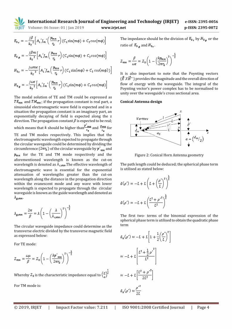
Figure 2: Conical Horn Antenna geometry
The path length could be deduced; the spherical phase term is utilised as stated below:
The first two- terms of the binomial expression of the spherical phase term is utilised to obtain the quadratic phase term
International Research Journal of Engineering and Technology (IRJET) e-ISSN: 2395-0056 Volume: 06 Issue: 01 | Jan 2019 www.irjet.net p-ISSN: 2395-0072
© 2019, IRJET | Impact Factor value: 7.211 | ISO 9001:2008 Certified Journal | Page 5
The path length term is utilised to determine the maximum aperture phase error(s) on the aperture fringe. Therefore we could state the following mathematically as:
Whereby, is the phase angle and is the approximated phase angle
Whereby
and
The maximum aperture phase angle is denoted as:
The approximated maximum aperture phase angle is denoted as:
Since
The path length and its approximated value could be subtracted to obtain the difference below:
Aperture diameter is equal to
The approximate maximum aperture phase error is expected to be larger than normal as a result of smaller aperture; as the aperture is reduced the approximate maximum aperture rises .The radiation properties could determine by utilising the electric field amplitude and phase over the aperture of the antenna. The dominant mode of the conical horn antenna is a distinctive approach to derive mathematical representation based on mode in the form of cylindrical Bessel function comprising either quadratic or spherical phase distribution. The conical horn antenna is considered as a truncated conical waveguide and this approach could be mathematically expressed as:
Whereby
, and
is the normalised incident electric field signal amplitude, is the Bessel function of the “m” order, whilst is
the first derivative of with respect to x. are the cylindrical coordinates from the source excitation on the horn antenna aperture. The two degrees of freedom affects the antenna performance; the axial length (L), aperture diameter ( ) and the flare angle ( ). The total comprehension of magnetic and electric potentials of dominant mode could be utilised to deduce the electric field using Maxwell’s equation and could be expressed as:
is the semi=flare angle, is the Hankel function of the second order of “m”, ( ) are the spherical coordinates in-line with the vertex of the conical horn antenna, “v” is the eigenvalue of mode on the waveguide of the conical horn antenna.
A small flare angle will ensure that the mathematical expression over the aperture of the antenna results with approximately equal amplitude and phase distribution as deduced via either the mode or via the truncated conical waveguide approach, but may differ slightly. The electric and magnetic current density over the aperture is essential to determine the electromagnetic far- field radiation.
The four-arm conical sinuous spiral antenna projected on the conical horn antenna has been designed using the conventional approach as originally invented by Duhamel H Raymond and the use of microwave theory for the conical horn antenna design. Duhamel stated that any number (N) of arms of the sinuous antenna can be designed, but odd

International Research Journal of Engineering and Technology (IRJET) e-ISSN: 2395-0056 Volume: 06 Issue: 01 | Jan 2019 www.irjet.net p-ISSN: 2395-0072
© 2019, IRJET | Impact Factor value: 7.211 | ISO 9001:2008 Certified Journal | Page 6
numbers of arms requires a complex feeding technique. Therefore, an even number of arms are more desirable and wide researched. The four arm sinuous antenna proposed to be projected on the horn antenna requires P cells per each arm' resulting to a total number of eight cells. The eighth cell of radius can be represented as or ; a 45 degrees was used as the alpha angle ( ) of the eighth cell in an angular coordinate system and delta of 22.5 degrees angle was used. The alpha and the delta have a direct impact on the antenna's gain, directivity, and overall impedance throughout the entire frequency bandwidth (DuHamel 1987). The combination of the alpha and delta should not exceed 70 degrees for a four-arm sinuous spiral antenna (Lizhong 2009). The ratio of the vicinal cell’s radius (also called the growth rate ( )) is essential in the design. If the
alpha ( ) and the radius ratio ( ) are obtained as a functional of P cells through methods such as squares, cube or Fibonacci series in order to achieve a numerical value(s) for the aforementioned variables. Therefore, the resulting sequence value(s) of and will be held constant; the resulting structure will yield a much wide bandwidth and the antenna will be called a quasi-logarithmic periodic antenna (DuHamel 1987). The overall sinuous antenna cone height is 0.48 m, growth rate ( ) of 0.8, 200 number of points, outer
radius of 0.27 m. The cells of the arms are lines of sheets with angle based on the coordinate system ( ) as an oscillating function of the radius from to in degrees for each cell and the next cell is interwoven and separated or isolated from the adjacent cell(s) by a close distance. The sheets has edges, which can describe by swiveling the center line via an angle of and - . The bandwidth is dominated by the radius ( ), and the numerical values of the alpha and the delta of the first and the last cells (DuHamel 1987).
The conical four-arm sinuous spiral antenna consisting of cell curves can be represented as:
(1)
The delta ( ) can be calculated as = ; whereby N is the
number of arms of sinuous antenna and r is a point at the polar coordinate system. The conical four-arm sinuous antenna have characteristics of dual circular polarization, good gain bandwidth and impedance antenna.
It can be designed without the cavity packed with absorbing materials to eliminate any reflection or standing wave; thereby increasing the bandwidth. Since, the four-arm sinuous spiral antenna consist of an array of N-number of
arms, emerging from a common plane with shared a point at the center of a polar coordinate system (r, ) and the point is considered as rotational symmetrical taking into consideration 360/N degrees; where N is the number of arms of the sinuous antenna. Each of the arms is made-up of a cascade of cells from one to P. The outer radius is denoted as and the outer radius is represented as p for the design parameter. The grow rate ( ) has a direct linkage between the outer and inner radius; the grow rate is directly proportional to ratio of .
(2)
is the wavelength at the highest operating frequency, which will be 720THz and is the wavelength at the lowest frequency cut-off .Therefore it can be calculated using the formulae below.
( ) (3)
( ) (4)
Whereby and are the initial cell radius and the alpha of the first cell and is the angle at the beginning of the first cell. The bandwidth can be increased by increasing or decreasing (DuHamel 1987). It has been stated that the bandwidth of the radiating waves of the sinuous antenna at the active region is inversely proportional to the parameter design of the antenna and a typical sinuous antenna will have a 3dB beam-width at an angle of about 60⁰ (DuHamel 1987).
The conical horn antenna is designed using the formulas below:
The diameter of the conical horn aperture can be determined using the formula below.
(5)
The length of the horn, not the aperture size, affects the gain of the conical horn antenna. The gain of the horn antenna can be deduced using the gain formula below.
(6)
Whereby, d is the diameter of the horn aperture in micro-meter (µm),
is the wavelength in Nano-meter (nm), L is the slant length,
A is equal to the aperture area in ,

International Research Journal of Engineering and Technology (IRJET) e-ISSN: 2395-0056 Volume: 06 Issue: 01 | Jan 2019 www.irjet.net p-ISSN: 2395-0072
© 2019, IRJET | Impact Factor value: 7.211 | ISO 9001:2008 Certified Journal | Page 7
is a pie or constant equivalent to the ratio of
is the dimensionless factor between 0 to 1 known as aperture efficiently; typical range for should be within the range of 0.4 to 0.8; most published journals estimated it to be 0.522 for horn antenna optimization and has a directed linkage with overall field distribution (Meera et al. 2014). The electromagnetic waves moving through the waveguide; the electromagnetic waves will not move at the speed of light as there will be some refectory and some will travel faster than others will. It is essential to determine the cut off frequency of the waveguide (Daniyan et al. 2014).
The antenna cut off frequency is directly related to the radius of the circular waveguide as shown below;
(7)
The speed of visible light is related to the permittivity, permeability, refractive index, frequency, energy and mass using the formulas below:
(8)
is speed of light through space =
f = frequency in THZ
= Refractive index
= Speed of Light through material
= Permittivity of free space (8.85419 )
= Energy in Joules
= wavelength in nm = Permeability of free space (4 )
= Planck’s constant
m = mass in Kg
To deduce the highest and lowest frequency of operation will be:
The wavelength ( ) of the electromagnetic waves inside the circular waveguide region of the horn antenna can be deduced as:
(9)
While is the wavelength of free space and can be
calculated as
The is a frequency lower than the calculated
Therefore, the circular waveguide length can be determined as:
(10)
The horn antenna waveguide radius is determined to 0.25 , the waveguide length is deduced to be 0.5 , the wall
thickness is 0.01 , the horn radius has been calculated as 0.69 and the horn length is determined as 0.99 .
Therefore, the bandwidth at the highest frequency is determined by
( ) (11)
The-feeding ports are isolated exciting the innermost part of the cell of the four arm sinuous antenna. The sinuous antenna structure uses two isolation feed excitation mode combination. The voltage is determined by
(12)
= Amplitude
N = Number of arms = 2
M = Number of modes is equal to two.
2.1 The Antenna Model

International Research Journal of Engineering and Technology (IRJET) e-ISSN: 2395-0056 Volume: 06 Issue: 01 | Jan 2019 www.irjet.net p-ISSN: 2395-0072
© 2019, IRJET | Impact Factor value: 7.211 | ISO 9001:2008 Certified Journal | Page 8
Fig 1: Inverted four arm sinuous spiral antenna embedded in a conical Horn antenna
The four-arm conical sinuous spiral antenna projected on a horn antenna designed to operate within the optical frequency band from 300 THz to 700 THz. The antenna is designed as a feeding antenna for a biological material designed on HFSS as unit cell. The antenna simulation results of the parameter shows a broadband characteristic from 350 THz to about 720 THz; which is within the visible light range. The voltage standing wave ratio (VSWR) of 1.2 averages was achieved at the operating frequency. The main lobe of the antenna was consistent in the same direction, unlike sinuous antenna on its own. The antenna is designed as a conical type of sinuous spiral antenna to obtain a simplex radiation over the optical bandwidth covering from 300THz to 700THz. The horn antenna was designed for a solution frequency at 606 THz. The sinuous antenna was been designed for the visible light spectrum with sinuous antenna design parameters such as the sinuous cone outer radius of 0.27 m, 200 points along the arm, 8 cells were achieved. The alpha angle ( ) of 45 degrees and delta ( ) of 22.5 degrees with growth rate ( ) of 0.8 and overall cone height of 0.48 m, port extension of 1000 and 2 port assignment. The sinuous antenna does not necessary require an infinite ground plane, the addition of a ground plane alters the overall impedance and the behavior of the antenna moderately.
1. Simulation Result
The operating frequency range is from 300 THz to 750THz; the antenna achieved a -25dB wide bandwidth characteristics across several frequencies with moderate changes in the main lobe. The polarization is not sustainable throughout the entire visible light spectrum. The results are presented below:
1) 3.1 The Return Loss
Visible light are transmitted from its source as scattered light components (electromagnetic components) in the forward direction and gets scattered upon interaction with matter. The term scattering could commonly refer to as transmission and reflection. The reflection coefficient is also known as the return loss or Scattering parameter (S-parameters). and are unequivocally the forward and reverse reflection coefficients, with the opposite port terminated in Z0 normally at 50 ohms. Corresponds to the mathematical expression of negative data of the input return loss from a 1-port with an termination on the opposite port. matches to the mathematical expression of negative data emanating from the output return loss of a 1-port with an termination on the opposite port.
The return loss shows the input and output ports relationship in terms of the level of considerable power reflected /radiated in or out of the antenna. It indicates the behavior of wideband antenna with approximately more than -20dB operating characteristics over the frequencies and allows high data rate due to wideband characteristics. At the frequency of 534.96THz, the S11 is equal to -36.92 dB approximately, thus implies that if 3 dB of power is accepted or delivered to the antenna, then the reflected power will be -33.92 dB. The accepted power is either absorbed as losses within the antenna or radiated out of the antenna. The return loss above implies that the antenna radiates best at 534.96THz, where S11 is at -36.92 dB. The antenna shows a characteristic of wideband behavior covering all the frequency of operation.
2) 3.2 Smith Chart Input impedance
The input impedance of the unmatched test antenna changes with changes in electrical length ; the changes occurs with change in frequency; therefore, we can conclude that the input impedance is frequency-depend and in line with derived equation below:
(16)
International Research Journal of Engineering and Technology (IRJET) e-ISSN: 2395-0056 Volume: 06 Issue: 01 | Jan 2019 www.irjet.net p-ISSN: 2395-0072
© 2019, IRJET | Impact Factor value: 7.211 | ISO 9001:2008 Certified Journal | Page 9
(17)
(18)
Whereby is Load impedance (measured in ohms)
is characteristics impedance (measured in ohms)
is the source impedance (measured in ohms)
is the propagation constant
is a reflection coefficient
Smith Chart creates a provision for the visualization of impedance transformation because of transmission lines expressed in very simple format. Let us consider the setup of impedance ZS is connected in series with the ZL connected at the end of the transmission line with characteristic impedance given by Z0:
Figure 3.6.3: Test antenna Input impedance
The load impedance is represented as the load impedance connected to a generator as a means of proving a voltage source for the antenna and the source has its associated source impedance (ZS) through a transmission line of length (L) and characteristic impedance (Z0). The input impedance could be found with the equation below with parameters such as the distance (L) from the load (ZL).
(19)
The input impedance (Zin) is deduced with a distance (L) down the transmission line on the Smith Chart. The equations below corresponds to the points on the input impedance on smith chart; the normalized load impedance is achieved by diving the load impedance (ZL) by characteristic impedance (Z0).
(20)
(21)
(22)
(23)
The input impedances could be calculated using the equations
On each point (m4) on the smith chart are the same distance away with the center reference of the Smith Chart. The complex input impedance equation above forms into a

International Research Journal of Engineering and Technology (IRJET) e-ISSN: 2395-0056 Volume: 06 Issue: 01 | Jan 2019 www.irjet.net p-ISSN: 2395-0072
© 2019, IRJET | Impact Factor value: 7.211 | ISO 9001:2008 Certified Journal | Page 10
simple circular motion on the Smith Chart; the impedance of a load a distance (L) down a transmission line could be determined easily by tracing in a circular fashion along the circle on the Smith Chart. Starting the trace from the lambda divided eight (one eighth of the antenna’s wavelength) down the transmission line on the input impedance plot above, the input impedance is determined by rotating 90 in the clockwise direction on the Smith Chart. Similarly, then the input impedance lambda divided by four (one quarter of the antenna’s wavelength) from the load impedance, the input impedance can be deduced by rotating 0 in the clockwise direction around the Smith Chart; It continually repeats every half-wavelength along the transmission line corresponds to a complete rotation trace from the start point. The circle trace cutting through load impedance (ZL) is synonymous a constant Voltage Standing Wave Ratio circle; the centered of the circle at the center on the smith chart is the reflection coefficient magnitude ( ).
The structure is more inductive in nature and could potentially act as high or low pass filter, the material could be metallic or dielectric inside the structure functioning as an impedance changing tool; causing the overall structure to become either more inductive or capacitive. The result of the receiving antenna is represented in Cartesian format (real and imaginary part).
is the wavelength
is the speed of light
f is the center frequency
(24)
The above equation could be transposed to calculate below:
(25)
Therefore
= 53306750.47+ 84438132.36j (Cartesian)
3) 3.3 Circular Polarization
Polarization is determined from the field of view of the receiver; the left or right hand dominance is resolved by pointing one’s right or left thumb toward the source of the transmission, against the propagation direction, and then corresponding to the pattern of the curving of the fingers to the temporal rotation of the field. It is essential for us to resolve from the receiver’s point of view looking into the source of transmission, if the electromagnetic wave is clockwise or anti-clockwise circularly polarized. At point of view is against the direction of propagation, detecting the direction of the field’s temporal rotation the right-handedness is said to be a clockwise rotation and left-handedness matches to an anti-clockwise rotation. The polarization could be mathematically represented as:
(26)
Right Hand Circular Polarization (3D)
Figure 3.6.4: Test antenna Right Hand Circular Polarization (3D visualization)
The 3D right hand circular polarization can be seen on the top and the 2D equivalent below: it indicates a right handiness/ clockwise direction (receiving) and the intensity of the polarization is below 0dB at -43dB at 0 degree with some reflections seen.
International Research Journal of Engineering and Technology (IRJET) e-ISSN: 2395-0056 Volume: 06 Issue: 01 | Jan 2019 www.irjet.net p-ISSN: 2395-0072
© 2019, IRJET | Impact Factor value: 7.211 | ISO 9001:2008 Certified Journal | Page 11
Right Hand Circular Polarization (2D)
Left Hand Circular Polarization (3D)
Figure 3.6.6: Test antenna Left Hand Circular Polarization (3D visualization)
Left Hand Circular Polarization (2D)
Figure 3.6.7: Test antenna Left Hand Circular Polarization (2D)
The 3D left hand circular polarization can be seen on the top and the 2D equivalent below: it indicates a left handiness or anti –clockwise direction (transmitting) and the intensity of the polarization is at 16.8788dB at 0 degree with some reflections seen at various points e.g. m14 at -13.1865dB.
4) Polar Plot Gain
Figure3.6.5: Test antenna Left Hand Circular Polarization (2D
Figure 3.6.8: Polar plot
The maximum direction of the radiation plot is towards the zero degrees and the plot shows minimum back-lope. The overall gain exceeds 40dB.
5) Voltage Standing Wave Ratio (VSWR)
An impedance usually terminates the transmission line; however, in some cases the termination may not be properly matched with the characteristic impedance; which may lead to unabsorbed power build-ups during termination. The unabsorbed power is reflected back, resulting to incident electromagnetic signals combination with the reflected electromagnetic signal to give rise to a voltage standing wave pattern. If an antenna exhibits a VSWR ratio of 1:1 or commonly written as 1; it could be explained as maximum measured voltage divided by the minimum measured voltage indicating that there are no power being reflected back to the source; which is not very realistic in the real-world antenna characteristics. Therefore, there are no wastage of power due to the antenna, there are no or minimal interference ability and there is no excessive heat created and signals could be amplified or manipulated better. The achievement of a VSWR of 1.2:1 or commonly states 1.2 is a very good characteristic of the antenna in the real world situation. However, if an antenna has shown a characteristic of VSWR from the range 2 and beyond is not desirable as about approximately 10 percent of the power is reflected back to the source at VSWR of 2:1 ratio. The VSWR beyond two is because of impedance mismatch. There are two ways of improving the impedance of an antenna; one method involves the use of Balun. It ensures that the source is approximately matched to the antenna and facilitate the production of unbalanced signal from a balance type. Otherwise, if the antenna shows characteristics of VSWR beyond two in only some of the frequencies of operation, an attenuator may be needed to check the emission or a six-decibel pad at the input were the connection is needed.
International Research Journal of Engineering and Technology (IRJET) e-ISSN: 2395-0056 Volume: 06 Issue: 01 | Jan 2019 www.irjet.net p-ISSN: 2395-0072
© 2019, IRJET | Impact Factor value: 7.211 | ISO 9001:2008 Certified Journal | Page 12
(27)
Where is the maximum measured voltage (v)
is the minimum measured voltage (V)
is the incident wave amplitude measured in volts
is the reflected wave amplitude also measured in volts
The result of the VSWR within the frequency within the point of m1 to m12 are very desirable; no power wastage and heat buildup. The result at this frequency of 360THz shows a negative VSWR; which does NOT indicate power wastage. VSWR is defined by the magnitude of the complex reflection coefficient (ρ),
VSWR determined when “ρ> ” could result to negative VSWR.
3. CONCLUSIONS
In this paper, the result shows that the current flowing on each arm is impaired, which are responsible for circular polarization and rotatory conformal pattern. The conical shape of the four-arm sinuous spiral antenna helps to achieve a unidirectional radiation pattern without any absorbing material added to the cavity or loaded on the cavity to absorb the reflected optical waves or the standing waves to achieve better gain in decibels (dB). The analyzed antenna indicates wideband properties based on the scattering parameters with excellent radiating beams. The electromagnetic waves are circularly polarized. The transition region of the antenna structure can be located between the feed point and active radiating region. The results show excellent bandwidth impudence from the frequency of 350 THz to 720THz for several frequency intervals within the visible light bandwidth and possess a dual polarization.
ACKNOWLEDGEMENT
The authors can acknowledge any person/authorities in this section. This is not mandatory.
REFERENCES
[1] O.L. Daniyan, et al., "Horn Antenna Design : The Concepts and Considerations". , 4(5), pp.706–708, 2014.
[2] M. N., Afsar, Y., Wang and R., Cheung, "Analysis and Measurement of a Broadband Spiral Antenna," IEEE Antennas and Propagation Magazine, 46, 1, pp. 59-64, 2004.
[3] R. Gawande, and R., Bradley, "Characterization of the active, inverted, conical sinuous antenna". XXIX General Assembly of URSI, 2008. [online] available from <http://cnfrs.institut-telecom.fr/pages/pages_ursi/URSIGA08/papers/A04p4.pdf> [24 August 2012].
[4] S. Lizhong, and S., Weihai, "Performance Simulation of a Kind of Conformal Sinuous Antenna with Four Arms, 2009.
[5] R. A., Mahnad, “A tribute to a great inventor: Raymond H. DuHamel 1921-1993," IEEE Antennas Propagation Magazine, vol. 36, pp 54–56, 1994.
[6] R. H., DuHamel, “Dual polarized sinuous antennas”, US Patent 4658262, 1987. [online] Available from <http://www.freepatentsonline.com/4658262.html> [2 March 2015].
[7] A. Sutinjo, and P.Hall, "Antenna Rotation Error Tolerance for a Low-Frequency Aperture Array Polarimeter". IEEE Transactions on Antennas and Propagation, 2014.
[8] A., Jiwani, T., Colegate, N., Razavi-Ghods, P., Hall, S. Padhi, and J. Geralt bij de Vaate, "Square Kilometre Array station configuration using two-stage", 2012. [online] Available at: https://arxiv.org/pdf/1211.4932.pdf [Accessed 11 Jun. 2014].
[9] S. Meera and Prof. A. K., Prakash, "Design of Linearly Polarized Sinuous Antenna in the Range of 2.5-6GHz", 2014. [online] Available from< http://www.ijareeie.com/upload/2014/april/51_Design.pdf> [8 March 2015]
[10] V., Gawande, P. Bilaye, and U. Desai, Low Cost Wireless Internet Access for Rural Areas using Tethered Aerostats. IEEE Region 10 and the Third international Conference on Industrial and Information Systems, 2008.
[11] M. L. T. Cossio, et al., (2012) Uma ética para quantos?[online] available from <http://www.ncbi.nlm.nih.gov/pubmed/15003161http://cid.oxfordjournals.org/lookup/doi/10.1093/ci/cir991http://www.scielo.cl/pdf/udecada/v15n26/art06.pdfhttp://www.s
Figure 3.6.9: VSWR

International Research Journal of Engineering and Technology (IRJET) e-ISSN: 2395-0056 Volume: 06 Issue: 01 | Jan 2019 www.irjet.net p-ISSN: 2395-0072
© 2019, IRJET | Impact Factor value: 7.211 | ISO 9001:2008 Certified Journal | Page 13
copus.com/inward/record.url?eid=2-s2.0-84861150233&partnerID=tZOtx3y1> [23 July 2014].
[12] A., Sandeeppalreddy, I., Zaghloul, R., Cheung, “An Optimized Lossy Back Cavity Loaded Four Arm Sinuous Antenna”, IEEE Trans.Antenna propagation, 2010.
[13] T., Colegate, P. Hall, and A. Gunst, "Cost-effective aperture arrays for SKA Phase 1: single or dual-band", 2012. [online] Arxiv.org. Available at: https://arxiv.org/pdf/1203.0413.pdf [Accessed 8 Aug. 2014].
[14] M. N., Afsar, Y., Wang and R., Cheung, "Analysis and Measurement of a Broadband Spiral Antenna," IEEE Antennas and Propagation Magazine, 46, 1, pp. 59-64, 2004.
[15] R. A. Mahnad,"A tribute to a great inventor: Raymond H. DuHamel 1921-1993," IEEE Antennas Propagation Magazine, vol. 36, pp 54–56, 1994.
[16] C.A., Balanis, Circular waveguides. Int. J. Electron., 1996(5), pp.551–564, 1996.
[17] G. Bank, et al., "THE SINUOUS ANTENNA: A DUAL POLARIZED ELEMENT FOR WIDEBAND PHASED ARRAY FEED APPLICATION element for wideband phased array feed application", (301), 1996.
[18] B., Baraiya, B. Makwana, and N., Bathani, "Simulation of the Gaussian profiled horn using variable depth slot mode converter". Internation Research Journal of Engineering and Technology (IRJET), 02(02), pp.417–420, 2015.
[19] S., Choi, "Efficient Antennas for Terahertz and Optical Frequencies", 2014.
[20] G. P., College, "Optimization and Designing of Conical Horn Antenna". , 7109, pp.36–37, 2011.
[21] J. M. Edwards, et al., "Dual-polarized sinuous antennas on extended hemispherical silicon lenses". IEEE Transactions on Antennas and PropagatiSon, 60(9), pp.4082–4091, 2012.
[22] W., Frei, "Modeling electromagnetic Wave and Periodic structure”, 2014.
[23] C. H. Geometry, and T., Ring, "A Dual-Mode Conical Horn Antenna for Rotationally Symmetric Beam. Antenna", pp.12–14, 2008.
[24] A. Kazemipour, et al., "The Horn Antenna as Gaussian Source in the mm-Wave Domain". Journal of Infrared, Millimeter, and Terahertz Waves, 35(9), pp.720–731, 2014. [online] Available from < http://link.springer.com/article/10.1007/s10762-014-0077-9\nhttp://link.springer.com/content/pdf/10.1007%2Fs10762-014-0077-9.pdf> [21 August 2013].
[26] A. A. Kishk, and C. S., Lim, "Comparative analysis between conical and gaussian profiled horn antennas". Progress In Electromagnetics Research, 38, pp.147–166, 2002.
[27] H. Li, et al, "DESIGN OF THE HIGH EFFICIENCY CIRCULAR HORN FEED FOR HIGH-POWER MICROWAVE SYSTEM". , 8, pp.1–12, 2009.
[28] J., Liang, "Antenna Wideband Study for Ultra Design and Applications Communication ", July 2006.
[29] R., O’Brient, "The sinuous antenna ". , vol.18, no, pp.40–48, 2010.
[30] T., Salimi, A. Maghoul, and A. A., Abbasid, "Design of a Compact Gaussian Profiled Corrugated Horn Antenna for Low Sidelobe-Level Applications". International Journal of Computer Theory and Engineering, 5(2), pp.223–226, 2013. [online] available from <http://www.ijcte.org/index.php?m=content&c=index&a=show&catid=48&id=795>[12 August 2013].
[32] K., Sultan, H. Abdullah, and E. Abdallah, "Low-SAR Miniaturized Handset Antenna Using EBG". INTECH, 2012. [online] Available at: http://dx.doi.org/10.5772/intechopen.70175 [Accessed 9 May 2014].
[33] A., Ahmed Akgiray, S. Sander Weinreb, and W. Imbriale, "Circular Quadruple-Ridged Flared Horn Achieving Near-Constant Beamwidth Over Multioctave Bandwidth: Design and Measurements". IEEE Transactions on Antennas and Propagation, Volume: 61, Issue: 3 March 2013. [online] Available at: https://ieeexplore.ieee.org/document/6362174/ [Accessed 5 Jun. 2014].
BIOGRAPHY
He studied at University of Birmingham and carried out some research at Coventry University. He formerly worked at Coventry University and aim to complete a PhD by publication at Warwick University.