INJNTU · 4 Define Bode plot? What are the advantages of Bode Plot? Remember 4 5 Define gain margin...
12
OBJECTIVES This course it is aimed to introduce the students the principles and applications of control systems in everyday life. The basic concepts of block diagram reduction, time analysis solutions to time invariant systems and also deals with the different aspects of stability analysis of systems in frequency domain and time domain QUESTION BANK ON SHORT ANSWER QUESTIONS S.No QUESTION BLOOMS TAXONOMY LEVEL PROGRAM OUTCOME UNIT-I INTRODUCTION TO CONTROL SYSTEMS AND TRANSFER FUNCTION REPRESENTAION 1 Explain control system? Remember 1 2 Define open loop control system Remember 1 3 Define closed loop control system. Remember 1 4 Define transfer function. Remember 1 5 Write the force balance equations of ideal mass element, dashpot element, spring element Understood 1 6 Write the analogous electrical elements in force voltage analogy for the elements of mechanical translational system Understood 1 7 Define signal flow graph? Understood 1 8 Define transmittance, sink and source? Understood 1 9 Write Masons Gain formula Understood 1 10 Discuss forward path? Understood 1 UNIT-II TIME RESPONSE ANALYSIS 1 Discuss Proportional controller and with advantages? Remember 2 2 Discuss the drawback in P-controller? Remember 2 3 Discus integral control action? What is the advantage and disadvantage in integral controller? Remember 2 4 Discuss PI, PD, and PID controller? Remember 2 5 Define Damping ratio. How the system is classified depending on the value of damping? Remember 2 INJNTU.COM INJNTU.COM INJNTU.COM INJNTU.COM
Transcript of INJNTU · 4 Define Bode plot? What are the advantages of Bode Plot? Remember 4 5 Define gain margin...

OBJECTIVES This course it is aimed to introduce the students the principles and applications of control systems in everyday life. The basic concepts of block diagram reduction, time analysis solutions to time invariant systems and also deals with the different aspects of stability analysis of systems in frequency domain and time domain
QUESTION BANK ON SHORT ANSWER QUESTIONS
S.No QUESTION BLOOMS
TAXONOMY LEVEL
PROGRAM OUTCOME
UNIT-I INTRODUCTION TO CONTROL SYSTEMS AND TRANSFER FUNCTION REPRESENTAION
1 Explain control system? Remember 1
2 Define open loop control system Remember 1
3 Define closed loop control system. Remember 1
4 Define transfer function. Remember 1
5 Write the force balance equations of ideal mass element, dashpot element, spring element
Understood 1
6 Write the analogous electrical elements in force voltage analogy for the elements of mechanical translational system
Understood 1 7 Define signal flow graph? Understood 1
8 Define transmittance, sink and source? Understood 1
9 Write Masons Gain formula Understood 1
10 Discuss forward path? Understood 1
UNIT-II TIME RESPONSE ANALYSIS
1 Discuss Proportional controller and with advantages? Remember
2
2 Discuss the drawback in P-controller? Remember 2 3 Discus integral control action? What is the advantage and
disadvantage in integral controller? Remember 2
4 Discuss PI, PD, and PID controller? Remember 2
5 Define Damping ratio. How the system is classified depending on the value of damping?
Remember 2
INJNTU.COM
INJNTU.COM INJNTU.COMINJNTU.COM

6 Distinguish between type and order of a system: Remember 2 7 Define rise, Delay time Remember 2 8 Define Peak time, settling time, Peak overshoot., Remember 2 9 Discuss the relation between generalized and static error coefficients Remember 2
10 List generalized error coefficients? Remember 2 UNIT-III
STABILITY ANALYSIS IN S-DOMAIN AND ROOT LOCUS TECHNIQUE
1 Define BIBO Stability. What is the necessary condition for stability? Remember 3
2 Describe characteristic equation? How the roots of characteristic equation are related to stability?
Remember 3
3 List the relation between stability and coefficient of characteristic polynomial?
Remember 3
4 Explain the nature of impulse response when the roots of characteristic equation are lying on imaginary axis?
Remember 3
5 Explain the nature of impulse response if the roots of characteristic equation are lying on right half s-plane?
Remember 3
6 Explain root locus? How will you find root locus on real axis? Remember 3
7 Discuss asymptotes? Remember 3
8 Define centroid, how it is calculated? Remember 3
9 List out breakaway point and break in point? Understood 3
10 Explain dominant pole? Understood 3
UNIT-IV FREQUENCY RESPONSE ANALYSIS
1 Define frequency response? With advantages of frequency response analysis?
Remember 4
2 Define frequency domain specifications? Remember 4
3 Define Resonant Peak. Remember 4 4 Define Bode plot? What are the advantages of Bode Plot? Remember 4 5 Define gain margin and phase margin? Remember 4 6 Define corner frequency. Remember 4
7 Explain Gain cross-over frequency and phase cross-over frequency? Remember 4 8 What is polar plot? Remember 4 9 What is lead compensator? Remember 4 10 What is lag compensator?? Remember 4
UNIT-V STATE SPACE ANALYSIS OF CONTINUOS SYSTEMS
1 What are the advantages of state space analysis? Evaluate 5 2 What are draw backs of transfer function model analysis
Analyze
5
3 What is state, state variable and state vector? ,?
Remember
5 4 What are the properties of state transition matrix? Understand 5 5 Write resolving matrix?
Evaluate
5
6 Define observability?
Evaluate
5 7 Define controllability?
Evaluate
5
8 How the modal matrix can be determined? Evaluate 5 9 What is i/p and o/p space? Evaluate
5
10 What are eigen values? Evaluate 5
INJNTU.COM
INJNTU.COM INJNTU.COMINJNTU.COM

GROUP-I (LONG ANSWER TYPE QUESTIONS)
S.No. QUESTION BLOOMS
TAXONOMY LEVEL
PROGRAM OUTCOME
UNIT-I
INTRODUCTION TO CONTROL SYSTEMS AND TRANSFER FUNCTION REPRESENTATION
1 Explain open loop & closed loop control systems by giving suitable
Examples & also highlights their merits & demerits.
Remember 1
2 Explain the difference between Open loop and Closed loop systems? Remember 1
3 Explain the classification of control systems? Remember 1
4 Explain mathematical model of a physical system? Explain briefly Remember 1
5 (a)Explain the traffic control systems using open loop and closed loopsystems?
(b) Explain the temperature control system using open loop and closed loopsystems?
(c) Human being is an example of closed loop system. Justify your answer?
Remember 1
6 Discus basis for framing the rules of block diagram reduction technique? What are drawbacks of the block diagram reduction technique?
Evaluate 1
7 How do you construct a signal flow graph from the equations? List advantages of signal flow graph over block diagram?
Evaluate 1
8 Explain about mason’s gain formula? Evaluate 1
9 Find the overall gain of the system shown below? Evaluate 1
10 Obtain the overall transfer function C/R from the signal flow graph shown. Evaluate 1
UNIT-II
TIME RESPONSE ANALYSIS
1 (a)Explain about various test signals used in control systems?
(b)Define time constant and explain its importance?
Remember 2
2 (a)Derive the expression for time domain specification of a under dampedsecond order system to a step input?
Evaluate 2
3 (a)Derive the transient response of under damped second order systemwhen excited by unit step input?
Evaluate 2
INJNTU.COM
INJNTU.COM INJNTU.COMINJNTU.COM

(b)Derive the transient response of un damped second order system whenexcited by unit step input?
4 (a)Derive the transient response of over damped second order system whenexcited by unit step input?
(b)Derive the transient response of critically damped second order systemwhen excited by unit step input?
Evaluate 2
5 (a)How steady state error of a control system is determined? How it can bereduced?
(b) Derive the static error constants and list the disadvantages?
Remember 2
6 For a system 𝐺 𝑠 𝐻 𝑠 =𝐾
𝑆2 𝑆+2 (𝑆+3) Find the value of K to limit steady
state error to 10 when input to system is 1 + 10𝑡 +40
2𝑡2
Apply 2
7 (a)Explain error constants Kp, Kv and Ka for type I system.(b) Explain error constants Kp, Kv and Ka for type II system.
Evaluate 2
8 (a)Explain the effect of PI control on the performance of control system
(b)Explain the effect of PD control on the performance of control system
Remember
&Evaluate
2
9 (a)What are P, D, and controller? Why D controller is not used in controlsystems?
(b) What are generalized error constants? State the advantages andsignificance of generalized error constants?
Understand 2
10 Discuss the advantages and disadvantages of proportional, proportional derivative, proportional integral control system.
Understand 2
UNIT-III
STABILITY ANALYSIS IN S-DOMAIN AND ROOT LOCUS TECHNIQUE
1 Define the terms
(i) Absolute stability (ii) marginal stability (iii) conditional stability (iv)stable system (v) Critically stable system (vi) conditionally stable system?
Remember 3
2 State Routh’s stability criterion. State their advantages
What are the limitations of Routh Hurwitz criteria?
Remember 3
3 List the necessary conditions to have all the roots of characteristics equation in the left half of s-plane?
Apply 3
4 By means of Routh criterion ,determine the stability represented by characteristic equation ,s4+2s3+8s2+4s+3=0
Apply 3
5 The open loop transfer function of a unity feedback system is given by
𝐺 𝑠 =𝐾
𝑆 1+0.25𝑆 (1+0.4𝑆).find the restriction on k so that the closed loop
system is absolutely stable.
Apply 3
6 (a)Explain the steps for the construction of root locus?
(b)From the given root locus plot, how can you determine the gain marginand phase margin for the specified gain value ‘k’
Apply 3
7 The open loop transfer function of a control system is given by G(s) H(s)
= 𝐾
𝑆 𝑆+6 (𝑆2+4𝑆+13) sketch complete root locus.
Apply 3
8 Check whether the points lie (-1+j) and (-3+j) lie on the root locus of a
system given by G(s) H(s)=1
𝑆+1 (𝑆+2).use the angle condition.
Apply 3
INJNTU.COM
INJNTU.COM INJNTU.COMINJNTU.COM

9 Sketch the root locus G(S)=K/s(s2+6s+10), H(S)=1 Apply 3
10 Check the stability of the given characteristic equation using Routh’s
method 𝑆6 + 2𝑆5 + 8𝑆4 + 12𝑆3 + 20𝑆2 + 16𝑆 + 16 = 0 Apply
UNIT-IV
FREQUENCY RESPONSE ANALYSIS
1 Discuss frequency response? What are advantages of frequency response analysis?
Understood 4
2 (a)write short notes on various frequency domain specifications
(b) Derive expression for resonant peak and resonant frequency and henceestablish correlation between time and frequency response.
Remember 4
3 Explain the steps for the construction of Bode plot? What are the advantages of Bode Plot?
Remember 4
4 Sketch the Bode plot for the open loop transfer function
𝐺 𝑠 =10(𝑆 + 3)
𝑆 𝑆 + 2 (𝑆2 + 4𝑆 + 100)
Apply 4
5 The open loop transfer function of a system is
𝐺 𝑠 = 𝐾
𝑆 1 + 𝑆 (1 + 0.1𝑆)
Determine the value of K such that (i) Gain Margin = 10dB and (ii) Phase Margin = 50 degree
Apply 4
6 Given the open loop transfer function 20
𝑠 1+3𝑠 (1+4𝑆)Draw the Bode plot and
hence the phase and gain margins.
Apply 4
7 Sketch the bode plot for a system with unity feedback having the transfer function, and assess its closed-loop stability.
𝐺 𝑠 = 75
𝑆(𝑠2 + 16𝑠 + 100)
Apply 4
8
Sketch the bode plot for a system with unity feedback having the transfer function, and assess its closed-loop stability.
𝐺 𝑠 = 10
𝑆 1+0.4𝑠 (1+0.1𝑠)
Apply 4
9 Draw the polar plot for open loop transfer function for unity feedback
system G(s)= 1
𝑠 1+𝑠 (1+2𝑆).determine gain margin, phase margin?
Apply 4
10 Discuss lead, lag compensator? Apply 4
UNIT-V
STATE SPACE ANALYSIS OF CONTINUOS SYSTEMS
4
1 Explain the state variable and state transition matrix? Creating &analyse
5
2 Write shot notes on formulation of state equations? Analyse 5
3 Derive the expression for the calculation of the transfer function from the state variables for the analysis of system?
Apply 5
4 Write short notes on canonical form of representation .list its advantages and disadvantages?
Evaluate 5
INJNTU.COM
INJNTU.COM INJNTU.COMINJNTU.COM

5 derive the controllable canonical form for the following transfer function 𝑌 𝑆
𝑈 𝑆 =
𝑏0𝑆𝑛 +𝑏1𝑆𝑛−1 + 𝑏2𝑆𝑛−2 +⋯…………………………….. 𝑏𝑛𝑆+𝑏𝑛
𝑆𝑛 +𝑎1𝑆𝑛−1 + 𝑎2𝑆𝑛−2 ………………………………………… 𝑆+𝑃𝑛
Remember
&Evaluate
5
6 derive the observable canonical form for the following transfer function 𝑌 𝑆
𝑈 𝑆 =
𝑏0𝑆𝑛 +𝑏1𝑆𝑛−1 + 𝑏2𝑆𝑛−2 +⋯…………………………….. 𝑏𝑛𝑆+𝑏𝑛
𝑆𝑛 +𝑎1𝑆𝑛−1 + 𝑎2𝑆𝑛−2 ………………………………………… 𝑆+𝑃𝑛
Understand 5
7 obtain the Jordan canonical form of state space representation for the following transfer function 𝑌(𝑆)
𝑈(𝑆)=
𝑏0𝑆𝑛 +𝑏1𝑆𝑛−1 + 𝑏2𝑆𝑛−2 +⋯………….. 𝑏𝑛𝑆+𝑏𝑛
𝑆+𝑃1 𝑛 𝑆+𝑃4 𝑆+𝑃5 ………………………………………… 𝑆+𝑃𝑛
Understand 5
8
Write properties of state transition matrix?
Understand 5
9
State and explain controllability and observability?
Creating &analyse
5
10 Write the necessary and sufficient conditions for complete state controllability and observability?
Evaluate 5
GROUP-III (ANALYTICAL QUESTIONS)
S.NoQUESTION BLOOMS
TAXONOMY LEVEL
PROGRAM OUTCOME
UNIT-I INTRODUCTION TO CONTROL SYSTEMS
1 Write the differential equations governing the Mechanical rotational system shown infig. Draw the Torque-voltage and Torque-current electrical analogous circuits.
Apply 1
2 Write the differential equations governing the Mechanical system shown in fig. and determine the transfer function
Apply 1
INJNTU.COM
INJNTU.COM INJNTU.COMINJNTU.COM
3 Obtain the transfer function X1(s)/F(s) for the mechanical system as shown in figure
Apply 1
4 Find the transfer function of the electrical network shown in figure Apply 1
5 For the mechanical system shown in Figure 3, determine the transfer function Y1(s)/F(s) and Y2(s)/F(s)
Apply 1
6 Determine the overall transfer function C(S)/R(S) for the system shown
in fig
Apply 1
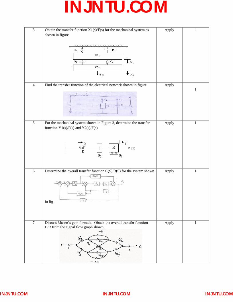
7 Discuss Mason’s gain formula. Obtain the overall transfer function
C/R from the signal flow graph shown. Apply 1
INJNTU.COM
INJNTU.COM INJNTU.COMINJNTU.COM

8 Determine the transfer function C(S)/R(S) of the system shown below fig. 2.3 by block diagram reduction method
Apply 1
9 Reduce the given block diagram and hence obtain the transfer function C(s)/R(s)
evaluate 1
10 Draw a signal flow graph and evaluate the closed-loop transfer function of a system whose block diagram is given as follows
Apply 1
UNIT-II
TIME RESPONSE ANALYSIS
1 A unity feedback system has 𝐺 𝑠 =40(𝑆+2)
𝑆 𝑆+1 (𝑆+4)
Determine (i) Type of the system (ii) All error coefficients and (iii) Error for the ramp input with magnitude 4
Apply 2
2 For a unity feedback system whose open loop transfer function is G(s) = 50/(1+0.1s)(1+2s) , find the position, velocity & acceleration error Constants.
Apply 2
3 A unity feedback system is characterized by an open loop transfer function
𝐺 𝑠 =𝐾
𝑆(𝑆 + 10)Determine gain ‘K’ so that system will have a damping ratio of 0.5. For
this value of ‘K’ determine settling time, peak overshoot and time to peak overshoot for a unit step input. Also obtain closed loop response in time domain
Apply 2
INJNTU.COM
INJNTU.COM INJNTU.COMINJNTU.COM

4 The open loop transfer function of a unity feedback system is given by
𝐺 𝑠 =𝐾
𝑆(𝑇𝑆+1) where K and T are positive constants. By what factor
should the amplifier gain be reduced so that the peck overshoot of unit step response of the system is reduced from 75% to 25%?
Apply 2
5 A unity feed-back system is characterized by the open-loop transfer
function: 1)1)(0.2ss(0.5s
1 )s(G
. Determine the steady-state
errors for unity-step, unit-ramp and unit-acceleration input. Also find the damping ration and natural frequency of the dominant roots.
Apply 2
6 The forward transfer function of a unity feedback type1, second order system has a pole at -2. The nature of gain k is so adjusted that damping ratio is 0.4. The above equation is subjected to input r(t)=1+4t. Find steady state error?
Apply 2
7 A feedback control system is described as G(s) = 50/s(s+2)(s+5) , H(s) = 1/s For a unit step input, determine the steady state error constants &
errors.
Apply 2
8 The closed loop transfer function of a unity feedback control system is given by- C(s)/R(s) = 10/(s2+4s+5) Determine (i) Damping ratio
(ii) Natural undammed resonance frequency(iii) Percentage peak overshoot(iv) Expression for error response
Apply 2
9 For a unity feedback system whose open loop transfer function is G(s) = 50/(1+0.1s)(1+2s) , find the position, velocity & acceleration error Constants.
Apply 2
10 The open loop transfer function of a control system with unity
feedback is given by )s1.0s(s
100)s(G
. Determine the steady state
error of the system when the input is 10+10t+4t2
Apply 2
UNIT-III STABILITY ANALYSIS IN S-DOMAIN AND ROOT LOCUS TECHNIQUE
1 With the help of Routh Hurwitz criterion comments upon the stability of the system having the following characteristic equation S6+s5-2s4-3s3-7s2-4s-4=0
Apply 3
2 How many roots does each of the following polynomials have in the Right half of the s-plane. s4+2s3+4s2+8s+15
Apply 3
3 The system having characteristic equation2 s4+4s2+1=0 (i) the number of roots in the left half of s-plane(ii) the number of roots in the right half of s-plane(iii)The number of roots on imaginary axis use RH stability criterion.
Apply 3
INJNTU.COM
INJNTU.COM INJNTU.COMINJNTU.COM

4 A unity feedback system has an open loop transfer function
5)4s2)(s(s
K )s(G
2
. Use RH test to determine the range of positive
values of K for which the system is stable
Apply 3
5 Find the range of K for stability of the system with characteristic equation s4+3s3+3s2+2s+k=0
Apply 3
6 For the unity feedback system the open loop T.F. is 𝐺 𝑠 =𝐾
𝑆 1+0.6𝑆 (1+0.4𝑆)
Determine(a) Range of values of K, marginal K (c) Frequency of sustained oscillations
Apply 3
7 Sketch the Root Locus for the unity feedback system with
𝐺 𝑠 𝐻 𝑠 =𝐾
𝑆 𝑆 + 1 𝑆 + 3 (𝑆 + 6)
Find the breakaway point on real axis and find K of damping ratio=0.5
Find
Evaluate 3
8 Sketch the complete Root Locus of the system
𝐺 𝑠 = 𝐾
𝑆 𝑆 + 2 (𝑆2 + 4𝑆 + 13)
Evaluate 3
9 Sketch root locus plot for unity feedback system whose open loop T.F
is given by G(S)=𝑘(𝑠+0.5)
𝑠2(𝑠+4.5)
Evaluate 3
10 Sketch the root locus plot of a unity feedback system whose open loop
T.F is G(s)=𝑠
𝑠2+4 (𝑠+2)
Evaluate 3
UNIT-IV
FREQUENCY RESPONSE ANALYSIS
1 Given damping ratio𝜉=0.7 and 𝜔n=10 rad/sec find the resonant peak, resonant frequency and band width.
Apply 4
2 For a second order system with unity feedback G(s)=200
𝑠(𝑠+8).find
various frequency domain specifications.
Apply 4
Sketch bode phase angle plot of a system G(s)=1
(1+𝑠)(1+2𝑠)
Apply 4
3 Draw the exact bode plots and find the gain margin and phase margin
of a system represented by G(s)H(s)=10(𝑠+1)
𝑠 (𝑠+0.05)(𝑠+3)(𝑠+5)
Apply 4
4 Draw the exact bode plots and find the gain margin and phase margin
of a system represented by G(s)=10(𝑠+1)
𝑠 (𝑠+0.05)(𝑠+3)(𝑠+5),H(S)=1
Apply 4
5 The open loop transfer function of a unity feedback system is
G(s)=50𝐾
𝑠 (𝑠+10)(𝑠+5)(𝑠+1)
(i)gain margin and phase margin(ii) the value o steady state error coefficient for a gain of 10db and thevalue which will make the closed loop system marginally stable.
Apply 4
INJNTU.COM
INJNTU.COM INJNTU.COMINJNTU.COM

6 Sketch the bode plot for transfer function G(s)=
𝐾𝑠2
(1+0.2𝑠)(1+0.02𝑠)and find value of K such that gain cross over
frequency is 5 rad/sec
Apply 4
7 Sketch the bode plot or a system G(s) =
15(𝑠+5)
𝑠 (𝑠2+16𝑠+100).hence
determine the stability of the system.
Apply 4
8 Sketch the bode plots of G(s)=
𝑒−0.1𝑠28.5
𝑠(1+𝑠)(1+0.1𝑠).hence find the gain
cross over frequency
Apply 4
9 A unity feedback control system has G(s)=
𝐾
𝑠(𝑠+1)(1+𝑠
10).find the
value of K so that GM=12db and PM=30deg.
Apply 4
10 Sketch polar plot for G(S) =
1
𝑆2(1+𝑠)(1+2𝑠)with unity feedback
system. Determine gain margin and phase margin.
Apply 4
UNIT-V STATE SPACE ANALYSIS OF CONTINOUS SYSTEMS
1 linear time invariant system is described by the following state model. Obtain the canonical form of the state model.
𝑥1 𝑥2
= −1 11 −2
𝑥1
𝑥2+ 0
1u and y= 1/3 −1/3
Creating &analyse
5
2. convert the following system matrix to canonical form
A= 1 2 1
−1 0 21 3 −1
Evaluate 5
3 a linear time invariant system is described by the following state model.obtain the canonical form of state model
𝑥1 𝑥 2
= −1 00 −3
𝑥1
𝑥2 + 1
1 u and y= −1 −2
𝑥1
𝑥2
Evaluate 5
4 convert the following system matrix to canonical form and hence
calculate the STM A= 4 1 −21 0 21 −1 3
Analyse 5
5 a system variables for the state variable representation of the system
are, A= −1 11 −2
,B= 01 , 𝐶 = 1 0
Determine the complete state response and the output response of the
system for the initial state X(0)= −10
Evaluate 5
INJNTU.COM
INJNTU.COM INJNTU.COMINJNTU.COM

6 for the state equation 𝑥 =Ax
Where A= 0 1 03 0 2
−12 −7 −6 .find the intial condition vector x(0)
which will excite only the mode corresponding to eigen value with the most negative real part.
Evaluate 5
7 consider the differential equation system given by 𝑦 + 3𝑦 + 2𝑌 = 0, y(0)=0.1,y(0)=0.05.
Obtain the response y(t),subjected to the given intial condition
Understand 5
8 consider the system described by the state equation
X(t)= 1 𝑒−𝑡
0 −1x(t)+
01
𝑢(𝑡)
Remember 5
9 determine the state controllability and observability of the following system
𝑥1 𝑥 2
= −3 −1−2 1.5
𝑥1
𝑥2 + 1
4 u
C=[0 1]
Apply 5
10 examine the observability of the system given below using canonical form
𝑥1 𝑥 2𝑥 3
= 0 1 00 1 10 −2 −3
𝑥1𝑥2𝑥3
+ 001 u
Y=[3 4 1] 𝑥1𝑥2𝑥3
Remember 5
INJNTU.COM
INJNTU.COM INJNTU.COMINJNTU.COM