Injection Molding · 2010-08-13 · Injection Molding ECONOMICS Injection molding machine is...
13
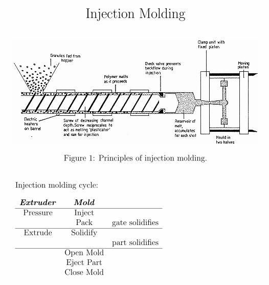
Injection Molding Figure 1: Principles of injection molding. Injection molding cycle: Extruder Mold Pressure Inject Pack gate solidifies Extrude Solidify part solidifies Open Mold Eject Part Close Mold
Transcript of Injection Molding · 2010-08-13 · Injection Molding ECONOMICS Injection molding machine is...
Injection Molding
Figure 1: Principles of injection molding.
Injection molding cycle:
Extruder MoldPressure Inject
Pack gate solidifiesExtrude Solidify
part solidifiesOpen MoldEject PartClose Mold
1
Inje
ctio
nM
oldin
g
2
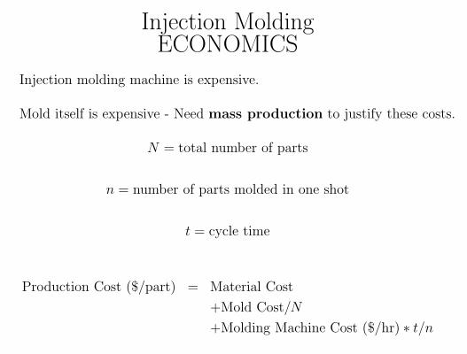
Injection MoldingECONOMICS
Injection molding machine is expensive.
Mold itself is expensive - Need mass production to justify these costs.
N = total number of parts
n = number of parts molded in one shot
t = cycle time
Production Cost ($/part) = Material Cost
+Mold Cost/N
+Molding Machine Cost ($/hr) ∗ t/n
3
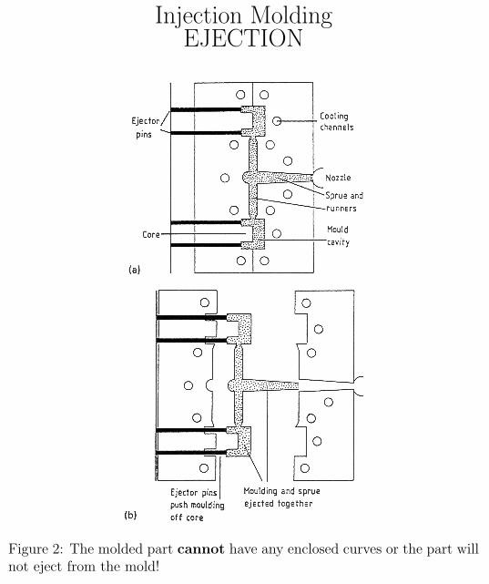
Injection MoldingEJECTION
Figure 2: The molded part cannot have any enclosed curves or the part willnot eject from the mold!
4
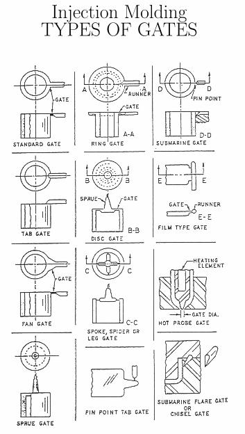
Injection MoldingTYPES OF GATES
5
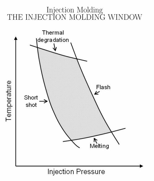
Injection MoldingTHE INJECTION MOLDING WINDOW
6
Injection MoldingCENTER-GATED DISK
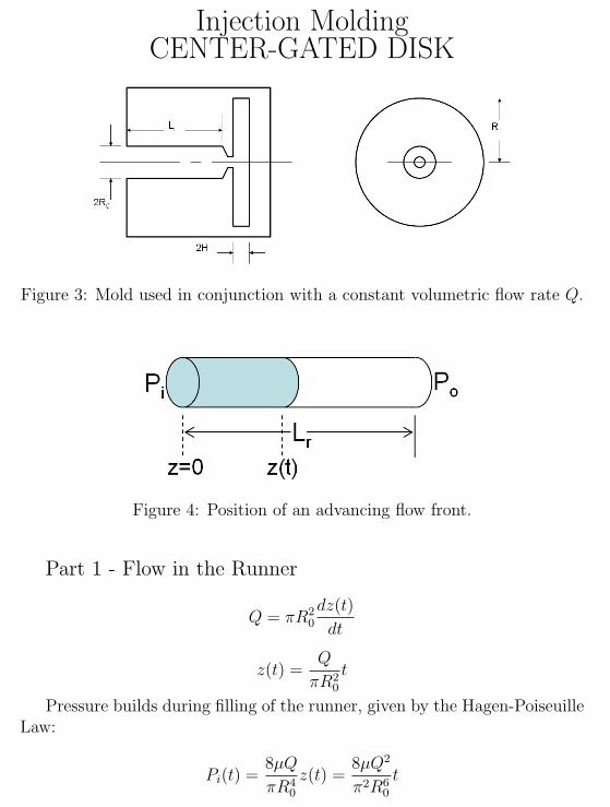
Figure 3: Mold used in conjunction with a constant volumetric flow rate Q.
Figure 4: Position of an advancing flow front.
Part 1 - Flow in the Runner
Q = πR20
dz(t)
dt
z(t) =Q
πR20
t
Pressure builds during filling of the runner, given by the Hagen-PoiseuilleLaw:
Pi(t) =8µQ
πR40
z(t) =8µQ2
π2R60
t
7
Injection MoldingCENTER-GATED DISK
At t = t0, the runner is filled (z = Lr)
t0 =πR2
0Lr
QPi(t0) =
8µQLr
πR40
For t > t0, the runner is full and the pressure drop along the runner isalways constant:
∆Pr = Pi − P0 =8µQLr
πR40
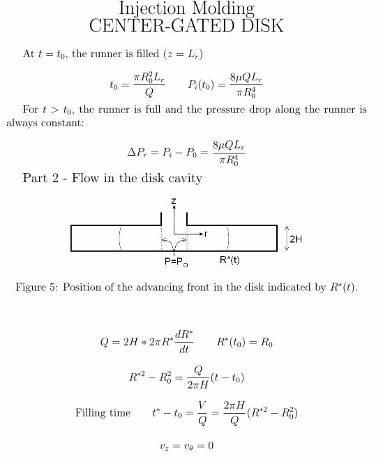
Part 2 - Flow in the disk cavity
Figure 5: Position of the advancing front in the disk indicated by R∗(t).
Q = 2H ∗ 2πR∗dR∗
dtR∗(t0) = R0
R∗2 −R20 =
Q
2πH(t− t0)
Filling time t∗ − t0 =V
Q=
2πH
Q(R∗2 −R2
0)
vz = vθ = 0
8
Injection MoldingCENTER-GATED DISK
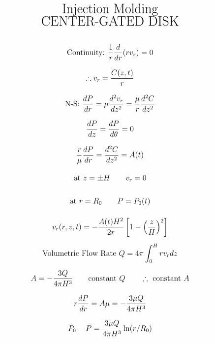
Continuity:1
r
d
dr(rvr) = 0
∴ vr =C(z, t)
r
N-S:dP
dr= µ
d2vr
dz2=
µ
r
d2C
dz2
dP
dz=
dP
dθ= 0
r
µ
dP
dr=
d2C
dz2= A(t)
at z = ±H vr = 0
at r = R0 P = P0(t)
vr(r, z, t) = −A(t)H2
2r
[1−
( z
H
)2]
Volumetric Flow Rate Q = 4π
∫ H
0
rvrdz
A = − 3Q
4πH3constant Q ∴ constant A
rdP
dr= Aµ = − 3µQ
4πH3
P0 − P =3µQ
4πH3ln(r/R0)
9
Injection MoldingCENTER-GATED DISK
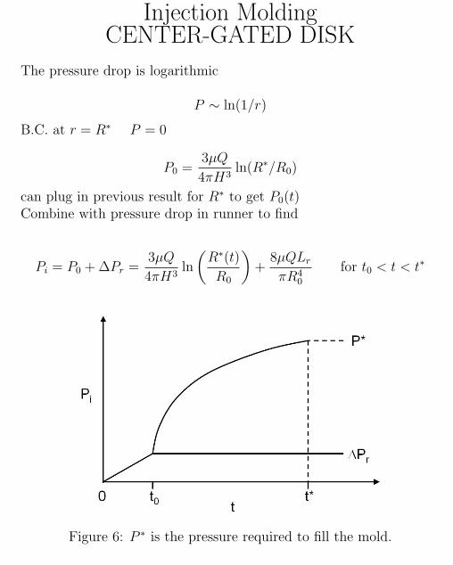
The pressure drop is logarithmic
P ∼ ln(1/r)
B.C. at r = R∗ P = 0
P0 =3µQ
4πH3ln(R∗/R0)
can plug in previous result for R∗ to get P0(t)Combine with pressure drop in runner to find
Pi = P0 + ∆Pr =3µQ
4πH3ln
(R∗(t)
R0
)+
8µQLr
πR40
for t0 < t < t∗
Figure 6: P ∗ is the pressure required to fill the mold.
10
Injection MoldingPACKING STAGE
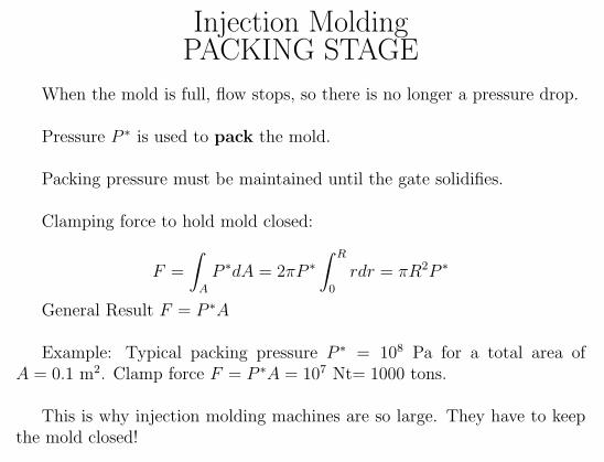
When the mold is full, flow stops, so there is no longer a pressure drop.
Pressure P ∗ is used to pack the mold.
Packing pressure must be maintained until the gate solidifies.
Clamping force to hold mold closed:
F =
∫A
P ∗dA = 2πP ∗∫ R
0
rdr = πR2P ∗
General Result F = P ∗A
Example: Typical packing pressure P ∗ = 108 Pa for a total area ofA = 0.1 m2. Clamp force F = P ∗A = 107 Nt= 1000 tons.
This is why injection molding machines are so large. They have to keepthe mold closed!
11
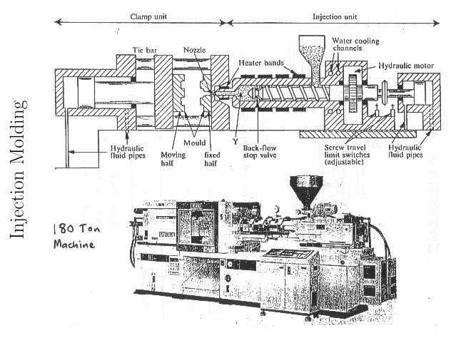
Injection MoldingSIZING AN INJECTION MOLDING
MACHINE
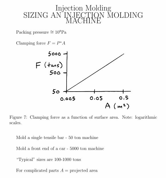
Packing pressure ∼= 108Pa
Clamping force F = P ∗A
Figure 7: Clamping force as a function of surface area. Note: logarithmicscales.
Mold a single tensile bar - 50 ton machine
Mold a front end of a car - 5000 ton machine
“Typical” sizes are 100-1000 tons
For complicated parts A = projected area
12
Injection MoldingCRITIQUE OF OUR MOLD-FILLING
CALCULATION
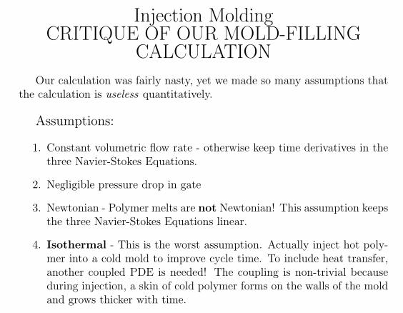
Our calculation was fairly nasty, yet we made so many assumptions thatthe calculation is useless quantitatively.
Assumptions:
1. Constant volumetric flow rate - otherwise keep time derivatives in thethree Navier-Stokes Equations.
2. Negligible pressure drop in gate
3. Newtonian - Polymer melts are not Newtonian! This assumption keepsthe three Navier-Stokes Equations linear.
4. Isothermal - This is the worst assumption. Actually inject hot poly-mer into a cold mold to improve cycle time. To include heat transfer,another coupled PDE is needed! The coupling is non-trivial becauseduring injection, a skin of cold polymer forms on the walls of the moldand grows thicker with time.
13