injection molded polypropylene manholes - · PDF fileinjection molded polypropylene manholes....
32
PIPES FOR LIFE INFRASTRUCTURE SYSTEMS www.pipelife.bg PRO injection molded polypropylene manholes
Transcript of injection molded polypropylene manholes - · PDF fileinjection molded polypropylene manholes....

INFRASTRUCTURE SYSTEMSPIPES FOR LIFE INFRASTRUCTURE SYSTEMSwww.pipelife.bg
PROinjection moldedpolypropylene manholes
2
PIPES FOR LIFE PRO
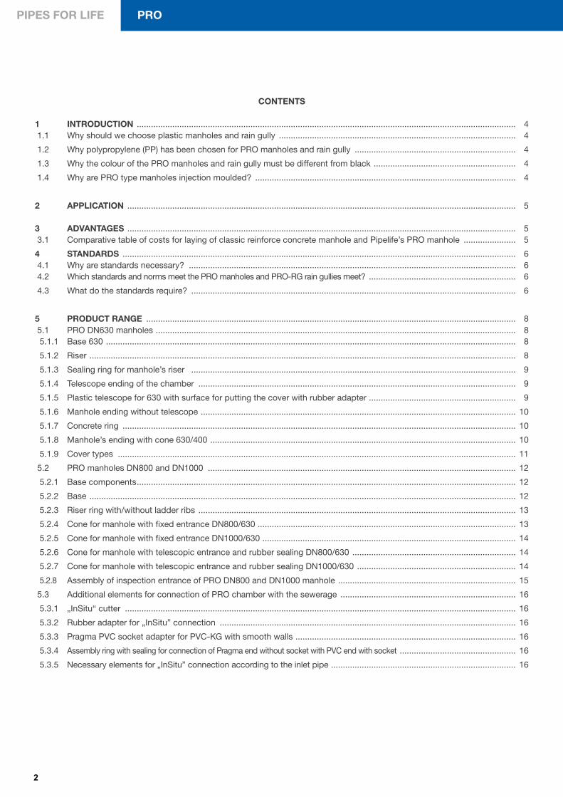
CONTENTS
1 INTRODUCTION ................................................................................................................................................................ 4 1.1 Why should we choose plastic manholes and rain gully .................................................................................................... 4
1.2 Why polypropylene (PP) has been chosen for PRO manholes and rain gully .................................................................... 4
1.3 Why the colour of the PRO manholes and rain gully must be different from black ............................................................ 4
1.4 Why are PRO type manholes injection moulded? .............................................................................................................. 4
2 APPLICATION .................................................................................................................................................................... 5
3 ADVANTAGES .................................................................................................................................................................... 5 3.1 Comparative table of costs for laying of classic reinforce concrete manhole and Pipelife’s PRO manhole ...................... 5
4 STANDARDS ...................................................................................................................................................................... 6 4.1 Why are standards necessary? .......................................................................................................................................... 6 4.2 Which standards and norms meet the PRO manholes and PRO-RG rain gullies meet? .............................................................. 6
4.3 What do the standards require? ......................................................................................................................................... 6
5 PRODUCT RANGE ............................................................................................................................................................ 8 5.1 PRO DN630 manholes ........................................................................................................................................................ 8 5.1.1 Base 630 ............................................................................................................................................................................. 8
5.1.2 Riser .................................................................................................................................................................................... 8
5.1.3 Sealing ring for manhole’s riser ......................................................................................................................................... 9
5.1.4 Telescope ending of the chamber ...................................................................................................................................... 9
5.1.5 Plastic telescope for 630 with surface for putting the cover with rubber adapter .............................................................. 9
5.1.6 Manhole ending without telescope ..................................................................................................................................... 10
5.1.7 Concrete ring ...................................................................................................................................................................... 10
5.1.8 Manhole’s ending with cone 630/400 ................................................................................................................................. 10
5.1.9 Cover types ........................................................................................................................................................................ 11
5.2 PRO manholes DN800 and DN1000 .................................................................................................................................. 12
5.2.1 Base components ................................................................................................................................................................ 12
5.2.2 Base .................................................................................................................................................................................... 12
5.2.3 Riser ring with/without ladder ribs ...................................................................................................................................... 13
5.2.4 Cone for manhole with fixed entrance DN800/630 ............................................................................................................. 13
5.2.5 Cone for manhole with fixed entrance DN1000/630 ........................................................................................................... 14
5.2.6 Cone for manhole with telescopic entrance and rubber sealing DN800/630 ..................................................................... 14
5.2.7 Cone for manhole with telescopic entrance and rubber sealing DN1000/630 ................................................................... 14
5.2.8 Assembly of inspection entrance of PRO DN800 and DN1000 manhole ........................................................................... 15
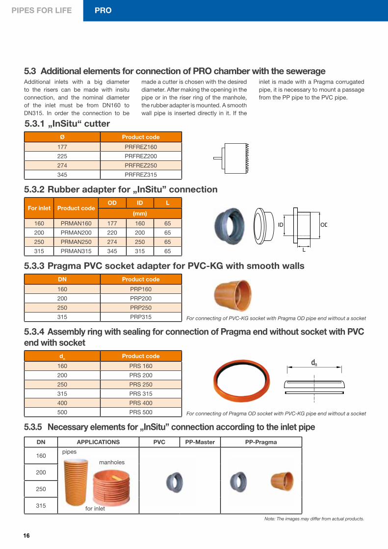
5.3 Additional elements for connection of PRO chamber with the sewerage .......................................................................... 16
5.3.1 „InSitu“ cutter ..................................................................................................................................................................... 16
5.3.2 Rubber adapter for „InSitu” connection ............................................................................................................................. 16
5.3.3 Pragma PVC socket adapter for PVC-KG with smooth walls ............................................................................................. 16
5.3.4 Assembly ring with sealing for connection of Pragma end without socket with PVC end with socket ................................................. 16
5.3.5 Necessary elements for „InSitu” connection according to the inlet pipe .............................................................................. 16
3
INFRASTRUCTURE SYSTEMS
6 DESIGN REQUIREMENTS ................................................................................................................................................ 17 6.1 Requirements for design of PRO ........................................................................................................................................ 17 6.1.1 Possible inlet angles ........................................................................................................................................................... 17
6.1.2 Cascade manholes ............................................................................................................................................................ 17
6.1.3 Types of inlets according to the type of the inlet pipe ........................................................................................................ 18
6.1.4. Concrete rings .................................................................................................................................................................... 18
6.1.5 Minimal elongations of the concrete ring and the cover of the PRO manhole cover ......................................................... 18
6.1.6 Necessary data for design .................................................................................................................................................. 19
7 REQUIREMENTS FOR LAYING ........................................................................................................................................ 20 7.1 Diagrams of PRO manhole laying ....................................................................................................................................... 20
7.2 Laying of PRO manholes in case of high underground waters .......................................................................................... 21
7.2.1 Filling the space between the shell, the base walls and the bottom of the manhole with low-slump concrete ................. 21
7.2.2 External concrete of the base with the inlets and the outlet of the manhole ...................................................................... 21
7.2.3 External concrete of the base with the inlets and the outlet of manhole with low-slump concrete above
the underground waters ...................................................................................................................................................... 21
8 ASSEMBLY PRO - SOFTWARE ........................................................................................................................................ 22
9 DIRECTIONS FOR LAYING AND ASSEMBLY .................................................................................................................. 23 9.1 Directions for laying and assembly of PRO-DN630, DN800 and DN1000 ......................................................................... 23
9.1.1 Preparation of the bedding layer and building of the manhole bottom .............................................................................. 23
9.1.2 Pipe connection assembly for inlet/outlet of the manhole bottom ..................................................................................... 23
9.1.3 Manhole rings mounting ..................................................................................................................................................... 24
9.1.4 Manhole cone mounting ..................................................................................................................................................... 24
9.1.5 Shortening the manhole cone ............................................................................................................................................. 24
9.1.6 Mounting the support concrete ring ................................................................................................................................... 25
9.1.7 Example of PRO manhole building ..................................................................................................................................... 25
9.1.8 Important directions for safety during assembly ................................................................................................................ 26
10 TRANSPORTATION - LOADING, UNLOADING AND STORAGE ..................................................................................... 26 10.1 Transport, delivery and storage .......................................................................................................................................... 26
11 HYDRAULIC CAPACITY OF PRO MANHOLES ................................................................................................................. 26
12 STATIC CALCULATION OF PRO MANHOLES ................................................................................................................. 29 12.1 Types of soils according to ENV 1046 ................................................................................................................................ 30 12.2 Compaction of the material for backfill ............................................................................................................................... 31
13 QUALITY MARK BY THE BULGARIAN WATER ASSOCIATION ..................................................................................... 31

4
PIPES FOR LIFE PRO
1 INTRODUCTION
1.1 Why should we choose plastic manholes and rain gullyPlastic manholes are the modern, en-vironment friendly and cheap in terms of operation alternative to the heavier, bigger and difficult to maintain concrete structures. Their guaranteed water-tight-ness, strength and low weight makes them suitable for integration in a com-plete sewer system of long and trouble-
free service life.
The use of such plastic materials, both pipes and manholes, offers a number of practical and economic advantages.
It is worth noting, most of all, their low weight, which implies easier transpor-
tation and installation, excellent corro-sion- and abrasion-proof properties, high resistance to wear and tear, in addition to durable impermeability. All that in ag-gregation results in low maintenance cost throughout their operation.
1.2 Why polypropylene (PP) has been chosen for PRO manholes and rain gullyPolypropylene (PP) is the latest genera-tion of thermoplastic materials used for the production of thermoplastic man-
holes. This material combines the hard-ness of polyvinyl chloride (PVC) and the elasticity of polyethylene (PE) to become
the most suitable and best balanced ma-terial capable of satisfying the complex requirements of BDS EN 13598-2.
1.3 Why the colour of the PRO manholes and rain gully must be different from blackThe practice of manufacturing ther-moplastic manholes by mould casting showed that the most common reason for adding black dye for the end prod-ucts is the fact that using recycled mate-
rials (scrap) turns the production process impossible to manufacture a product of homogenous color other than black.
This is the main reason why Pipelife is manufacturing its products in a color other than black - to prove once again indisputably that Pipelife uses only and exclusively primary raw materials.
1.4 Why are PRO type manholes injection moulded?For the making of PRO manholes Pipelife has chosen the method of injection moulded components. This method allows the achievement of high density and ribbed external surface. Each and every component has been designed and manufactured in consideration of its functions in the manhole operation and services its structural integrity as a finished end product meeting all standard requirements.
- the double ribbed bottom is capable of withstanding a 5 m long water column, which guarantees the intactness of sewer shape and its hydraulic conductivity;
- the barrels are cast with step attachments, which guarantees their strength and ease for inspection. The ribbed external surface ensures better cohesion between the manhole and the backfill against floating;
- the cone is ribbed and tested for heavy traffic areas up to 40 t.- they can be laid up to 6.5 m depth in heavy traffic areas and up to 2 m depth from the manhole bottom.
Disadvantages of the rotation cast manholes:- the rotation cast components have smooth walls, in the best case it may be corrugated but it cannot be thicker than 12 mm, which
precludes the making of any thicker zones in the bottom or ribbing of the barrels in order to achieve the minimum ring hardness required by the applicable standard > SN2;
- the installation of rotation cast manholes deeper than 2 m is risky and the manhole should be supported additionally;- a significant disadvantage of rotation casting is that inlets and the outlet cannot be made as hard as needed in the area of coupling
the socket with the inlet pipe. There is a high risk of loss of water-tightness;- difficult calibration of the socket and smooth part of the coupling, which in combination with the shrinkage of material leads to
insecure joints and leakages from and to the system;- the steps are cast in oval shape, which makes them uncomfortable for inspections;- the base is the final cast component and the lack of a ribbed bottom makes the base not hard enough, which results in deflection
if the level of underground water is high.
5
INFRASTRUCTURE SYSTEMS
3 ADVANTAGES ● Resistance to abrasion;
● Resistance to chemicals(from pH=2 to pH=12)
● Resistance to high temperatures (60°C for continuous flow, and 95°C to 100°C for intermittent flow);
● Resistance to shocks – conforming to the requirements of BDS EN 1411 and BDS EN 1206;
● Guaranteed hardness SN ≥ 2 kN/m2 throughout the manhole height – conforming to the requirements of BDS 13598-2:2009 and ISO 9969;
● Reinforced ribbed bottom to resist high underground water level;
● Modular system – easy to transport and allowing fast and easy installation on the spot;
● Mould cast elastomer sealing rings EPDM 45 ± 5. BDS EN 681-1;
● Option for joining at different angles and different heights - more than 3000 combinations are possible;
● All PRO type manholes can be equipped with telescopic covers;
● High hydraulic conductivity thanks to the smooth-surface invert;
● Guaranteed water-tightness of the system ranging from -0.3 bar to +0.5 bar in accordance with the requirements of BDS EN 1277;
● Light weight;
● Long service life;
● Compatible combination with smooth-walled PVC pipes, KG type, and profiled pipes, types Pragma and Pragnum, using unique system of fittings and adaptors;
● All inlets and outlets are equipped with sockets and rubber sealing for fast and easy installation;
● Integrated unit in a complete sewer system of pipes, fittings and facilities;
● Ease of inspection thanks to the steps meeting the requirements of EN 13101 and EN 14396
● Resistance to floating thanks to the ribbed external surface;
● All components of the PRO type system are manufactured under continuous production control of raw materials and end products.
3.1 Comparative table of costs for laying of classic reinforce concrete manhole and Pipelife’s PRO manhole
Manhole, DN1000, made of concrete components up to 3 m high, without cover, BGN
Manhole, DN1000, PRO type, up to 3 m high, straight, DN315, without cover, BGN
I. Labor: 36,42 20.03
ІI. Machines and equipment 113,22 0,00
IІІ. Extra cost 81,71 20.03
Manhole price 1100.00 2013,00
Unit price, including 10% profit 1354,49 2214.3
Number of manholes that could be installed per work day: ● Concrete: 2-3
● PRO: 8-10
2 APPLICATIONPRO type manholes are used for:
● Revision and inspection of gravity sewer networks;
● Connection between sewer networks at different levels;
● Changing the sewer network way in both horizontal and vertical direction;
● Changing the gradient and cross section of the sewer network;
● A draw tank for PROFOS type sewer pumping plant;
● Rainwater harvesting;
● Water meter boxes, type PRO-WM;
● For specific industrial needs;
● Revision and inspection of telecommunication and electric power distribution networks.

6
PIPES FOR LIFE PRO
4 STANDARDS
4.1 Why are standards necessary?The standards are a combination of rules and norms based on practical and theoretical observations and studies of the technical parameters which the products should meet. They define minimal requirements for quality of the
specific product. At the same time they guarantee compatibility of products made by different manufacturers.
All this make the standard extremely important because it guarantees to all
parties: designers, engineers, architects, builders, clients, control authorities that the product which they use meets the specific application and possesses all the qualities for unhindered, flawlessand long-term exploitation.
The standard requires water-tightness: from - 0,3 bar negative pressure to +0,5 bar positive pressure
● Shock-resistance – it is tested according to EN 12061.
The tests with a weight which falls from the height of 2,5 m weighing 1 kg and cone radius 50 mm are performed close to the injection points of the shell at 23°C. The zone close to the injection point is accepted as the weakest spot. The standard does not allow cracks and substantial deformations.
● Mechanical strength of the connections. It is tested according to EN 12256.The standard defines the mechanical strength of the connections as it requires when specific force is applied at a specific distance from the connection, the displacement to remain within 170 mm without breaking the connection integrity at the critical spot (see Figure 1).
Figure 1
4.2 Which standards and norms meet the PRO manholes and PRO-RG rain gullies meet?The PRO manholes are manufactured and meet the requirements of the stand-ard EN 13598-2:2009 Plastics piping systems for nonpressure underground
drainage and sewerage - Unplasticized poly (vinyl chloride) (PVC-U), polypropyl-ene (PP) and polyethylene(PE).
Part 2: Specifications for manholes and inspection chambers in traffic areas and deep underground installations.
4.3 What do the standards require?The standard EN 13598-2:2009 defines minimal requirements for manholes and inspection chambers in traffic zones and deep underground installations with regard to the following characteristics:
● Definition of the manhole types according to EN 13598-2:2009
Inspection chambers (without man access) with a diameter of the base DN/ID - 200, 250,315,400 и 600.Manholes (with man access) with a diameter of the base > DN/ID800.
● Ring stiffness - SN>2 к№м2 according to ISO 9969.
It is tested according to EN 14982 and concerns the components of the manhole: base, riser rings and cone.
● Water-tightness. It is tested according to EN 1277.
This method tests the system ability to hold the liquids from and out of the system (filtration/infiltration). The test confirms the watertightness between the elements of the manhole and the connection with the sewer system. This tightness of the system concerns the ecological aspect for protection of soil and waters.
Note: The images may differ from actual products.
7
INFRASTRUCTURE SYSTEMS
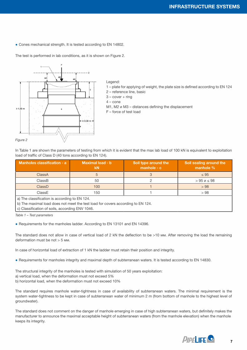
● Cones mechanical strength. It is tested according to EN 14802.
The test is performed in lab conditions, as it is shown on Figure 2.
In Table 1 are shown the parameters of testing from which it is evident that the max lab load of 100 kN is equivalent to exploitation load of traffic of Class D (40 tons according to EN 124).
Figure 2
Table 1 – Test parameters
Manholes classification - a Maximal load - bkN
Soil type around the manhole - c
Soil sealing around themanhole %
ClassA 5 3 ≤ 95
ClassB 50 2 > 95 и ≤ 98
ClassD 100 1 > 98
ClassE 150 1 > 98
a) The classification is according to EN 124.b) The maximal load does not meet the test load for covers according to EN 124.c) Classification of soils, according ENV 1046.
● Requirements for the manholes ladder. According to EN 13101 and EN 14396.
The standard does not allow in case of vertical load of 2 kN the deflection to be >10 мм. After removing the load the remaining deformation must be not > 5 мм.
In case of horizontal load of extraction of 1 kN the ladder must retain their position and integrity.
● Requirements for manholes integrity and maximal depth of subterranean waters. It is tested according to EN 14830.
The structural integrity of the manholes is tested with simulation of 50 years exploitation:a) vertical load, when the deformation must not exceed 5%b) horizontal load, when the deformation must not exceed 10%
The standard requires manhole water-tightness in case of availability of subterranean waters. The minimal requirement is the system water-tightness to be kept in case of subterranean water of minimum 2 m (from bottom of manhole to the highest level of groundwater).
The standard does not comment on the danger of manhole emerging in case of high subterranean waters, but definitely makes the manufacturer to announce the maximal acceptable height of subterranean waters (from the manhole elevation) when the manholekeeps its integrity.
Legend:1 – plate for applying of weight, the plate size is defined according to EN 1242 – reference line, basic3 – cover + ring4 – coneM1, M2 и M3 – distances defining the displacementF – force of test load
8
PIPES FOR LIFE PRO
Note: The images may differ from actual products.
5 PRODUCT RANGE
5.1 PRO DN630 manholes5.1.1 Base 630
5.1.2 Riser
Bottomtype
Effectiveheight
Възможен DN
Base 1
HB
160 200 - - -
Base 1,5 - - 250 315 -
Base 2 - - - - 400
*all sizes are in mmNote: НМ – depth of putting the riser
Product code ID/OD (mm)Calculated length from the project
L (mm)Effective height
H2 (mm)
PRO-PPDWRISER630 545/630 500 500
Base DN Outlet Inlet 1 Inlet 2 Inlet 3
DN630 160, 200, 250, 315, 400 160, 200, 250, 315,400 160, 200, 250, 315 160, 200, 250, 315
9
INFRASTRUCTURE SYSTEMS
Note: The images may differ from actual products.
5.1.5 Plastic telescope for 630 with surface for putting the cover with rubber adapter
HT
Product code Size f (mm)Weight
(кг)H (mm)
Minimal depth of putting in hR (mm)
HТ
PRO-T630/535x0.5 535/805 50 10 500 150 350
5.1.4 Telescope ending of the chamber
Product code OD ID
PRK 630 640 600
5.1.3 Sealing ring for manhole’s riser
telescope
base
sealing ring
riser
H cover
HP
HB
H2
HT
h R
10
PIPES FOR LIFE PRO
5.1.6 Manhole ending without telescope
5.1.7 Concrete ring
Dimensions are shown in mm
Dimensions are shown in mm
Product code Dimension H
PRO-Frame630 1040/1000 640
PRO Adaptive Frame630 940/640 640
5.1.8 Manhole’s ending with cone 630/400
Product code Dimension H Effective height
PRO-Con630/400 590/400 461 400Ø 590
Ø 400
H
* Cone 630/400 can be completed with a telescopic cover 315/400 (see catalogue PRAKTO)
Note: The images may differ from actual products.
1040
1040
160
840
640200
940640150 150
55
135
940840
131 59
The purpose of concrete ring is to distribute the dynamic load caused by traffic to the soil .
Adapting concrete ring, consisting of two parts with cross sectional cylindrical profile, which in addition to distributing the traffic load to the soil, can create inclined surface to go with the road gradient by axial rotation of both parts.
H cover
HP
HB
H2
11
INFRASTRUCTURE SYSTEMS
Dimensions are shown in mm
5.1.9 Cover types All PRO manholes can be equipped with covers of the following types:
● A15 = 1.5 tons load
● B125 = 12.5 tons load
● C250 = 25 tons load
● D400 = 40 tons load
according to BDS EN 124.
PP plastic cover – DN400, A15 for cone 630/400
Product code Dimension H
KGDOV400-A15 400 80
PRO-Cover630-A15-PE 630 100
Ø 400
H
DN400 EN 124 A15
Note: The images may differ from actual products.
PE plastic cover – DN630, A15
Covers DN600 – A15, B125, D400 for pedestrian and traffic areas
Plastic cover for extendable pipe DN630, to be installed over the barrel and fixed to it using screws; suitable for lawns and pedestrian areas.
Pipelife’s PRO manholes can be furnished with all types of covers DN600 available on the market with different load class according to EN 124.
12
PIPES FOR LIFE PRO
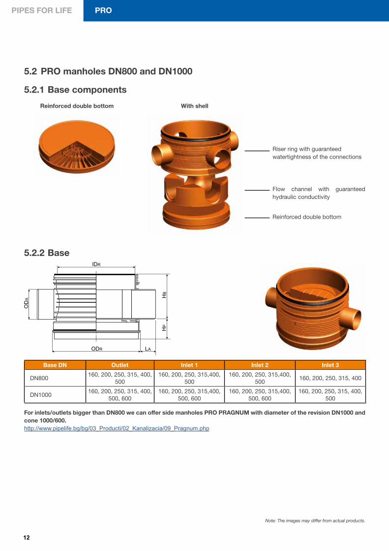
For inlets/outlets bigger than DN800 we can offer side manholes PRO PRAGNUM with diameter of the revision DN1000 and cone 1000/600. http://www.pipelife.bg/bg/03_Producti/02_Kanalizacia/09_Pragnum.php
With shell
Flow channel with guaranteed hydraulic conductivity
Reinforced double bottom
Riser ring with guaranteed watertightness of the connections
Reinforced double bottom
5.2 PRO manholes DN800 and DN1000
5.2.2 Base
5.2.1 Base components
Base DN Outlet Inlet 1 Inlet 2 Inlet 3
DN800160, 200, 250, 315, 400,
500160, 200, 250, 315,400,
500160, 200, 250, 315,400,
500160, 200, 250, 315, 400
DN1000160, 200, 250, 315, 400,
500, 600160, 200, 250, 315,400,
500, 600160, 200, 250, 315,400,
500, 600160, 200, 250, 315, 400,
500
Note: The images may differ from actual products.
13
INFRASTRUCTURE SYSTEMS
ODE
ODC
Hef
H
5.2.3 Riser ring with/without ladder ribs
Note: When using a riser without ladder ribs, an aluminium ladder is used/see 5.2.4 Aluminium ladder/
Riser Cutting line 1 Cutting line 2 Total
DN800 100 100 200
DN1000 100 150 250
Name Product code IDR Ladder
Riser with ladder ribs 800
PRO-RISER800-L 800 yes
Riser without ladderribs 800
PRO-RISER800-WO-L 800 no
Riser with ladder ribs 1000
PRO-RISER1000-L 1000 yes
Riser without ladderribs 1000
PRO-RISER1000-WO-L 1000 no
Possible reduction of the risers’ height.
Dimensions are shown in mm
Note: The images may differ from actual products.
5.2.4 Cone for manhole with fixed entrance DN800/630
Product code ODE H Hef ODC
PRO-Con800/630-Fix 630 430 340 910
Note: It is possible a maximal reduction/extension of the height НЕ of 10 см
HR
250
30
IDR
cutting line 1ladder
ladder
cutting line 2
ODR
400
HS
14
PIPES FOR LIFE PRO
ODE
ODC
Hef
H
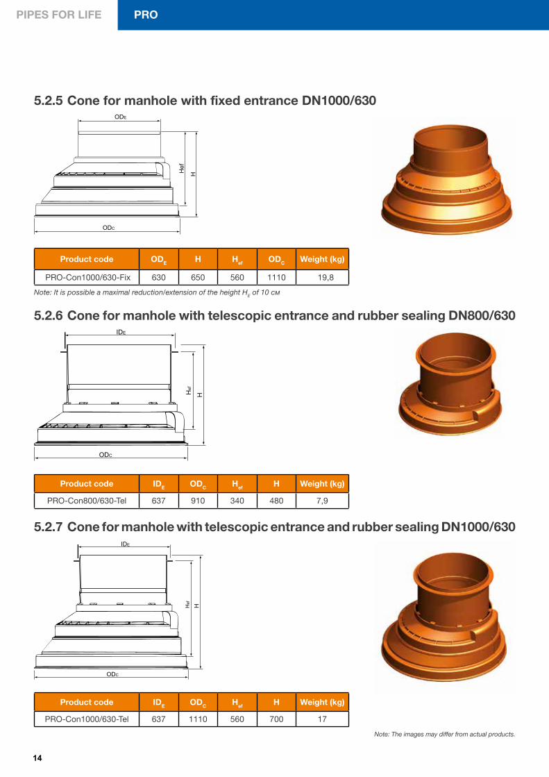
5.2.5 Cone for manhole with fixed entrance DN1000/630
Product code ODE H Hef ODC Weight (kg)
PRO-Con1000/630-Fix 630 650 560 1110 19,8
Note: It is possible a maximal reduction/extension of the height НЕ of 10 см
Product code IDE ODC Hef H Weight (kg)
PRO-Con800/630-Tel 637 910 340 480 7,9
5.2.6 Cone for manhole with telescopic entrance and rubber sealing DN800/630
ODC
Hef
H
IDE
Product code IDE ODC Hef H Weight (kg)
PRO-Con1000/630-Tel 637 1110 560 700 17
5.2.7 Cone for manhole with telescopic entrance and rubber sealing DN1000/630
ODC
Hef H
IDE
Note: The images may differ from actual products.
15
INFRASTRUCTURE SYSTEMS
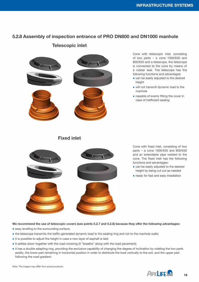
5.2.8 Assembly of inspection entrance of PRO DN800 and DN1000 manhole
Note: The images may differ from actual products.
Telescopic inlet
Fixed inlet
Cone with telescopic inlet, consisting of two parts – a cone 1000/630 and 800/630 and a telescope, the telescope is connected to the cone by means of a rubber seal. The telescope has the following functions and advantages:
● can be easily adjusted to the desired height
● will not transmit dynamic load to the manhole
● capable of evenly fitting the cover in case of inefficient sealing
Cone with fixed inlet, consisting of two parts – a cone 1000/630 and 800/630 and an extendable pipe welded to the cone. The fixed inlet has the following functions and advantages:
● can be easily adjusted to the desired height by being cut out as needed
● ready for fast and easy installation
We recommend the use of telescopic covers (see points 5.2.7 and 5.2.8) because they offer the following advantages:
● easy levelling to the surrounding surface;
● the telescope transmits the traffic-generated dynamic load to the sealing ring and not to the manhole walls;
● it is possible to adjust the height in case a new layer of asphalt is laid;
● it settles down together with the road covering (it “breaths” along with the road pavement);
● it has a double adapting ring, providing the exclusive capability of changing the degree of inclination by rotating the two parts axially, the lower part remaining in horizontal position in order to distribute the load vertically to the soil, and the upper part following the road gradient.
16
PIPES FOR LIFE PRO
5.3 Additional elements for connection of PRO chamber with the sewerageAdditional inlets with a big diameter to the risers can be made with insitu connection, and the nominal diameter of the inlet must be from DN160 to DN315. In order the connection to be
made a cutter is chosen with the desired diameter. After making the opening in the pipe or in the riser ring of the manhole, the rubber adapter is mounted. A smooth wall pipe is inserted directly in it. If the
inlet is made with a Pragma corrugated pipe, it is necessary to mount a passage from the PP pipe to the PVC pipe.
ID OD
L
For inlet Product codeOD ID L
(mm)
160 PRMAN160 177 160 65
200 PRMAN200 220 200 65
250 PRMAN250 274 250 65
315 PRMAN315 345 315 65
5.3.2 Rubber adapter for „InSitu” connection
Ø Product code
177 PRFREZ160
225 PRFREZ200
274 PRFREZ250
345 PRFREZ315
5.3.1 „InSitu“ cutter
5.3.3 Pragma PVC socket adapter for PVC-KG with smooth wallsDN Product code
160 PRP160
200 PRP200
250 PRP250
315 PRP315 For connecting of PVC-KG socket with Pragma OD pipe end without a socket
5.3.4 Assembly ring with sealing for connection of Pragma end without socket with PVC end with socket
dn Product code
160 PRS 160
200 PRS 200
250 PRS 250
315 PRS 315
400 PRS 400
500 PRS 500 For connecting of Pragma OD socket with PVC-KG pipe end without a socket
DN APPLICATIONS PVC PP-Master PP-Pragma
160
200
250
315
pipes
manholes
for inlet
5.3.5 Necessary elements for „InSitu” connection according to the inlet pipe
Note: The images may differ from actual products.
17
INFRASTRUCTURE SYSTEMS
Figure 3
Figure 2
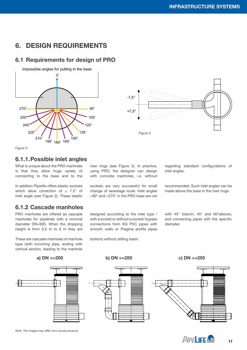
6. DESIGN REQUIREMENTS
6.1 Requirements for design of PRO
6.1.1. Possible inlet anglesWhat is unique about the PRO manholes is that they allow huge variety of connecting to the base and to the
riser rings (see Figure 3). In practice, using PRO, the designer can design with concrete manholes, i.e. without
regarding standard configurations of inlet angles.
In addition Pipelife offers elastic sockets which allow correction of ± 7.5° of inlet angle (see Figure 2). These elastic
sockets are very successful for small change of sewerage route. Inlet angles <90° and >270° in the PRO base are not
recommended. Such inlet angles can be made above the base in the riser rings.
6.1.2 Cascade manholes PRO manholes are offered as cascade manholes for pipelines with a nominal diameter DN<600. When the dropping height is from 0,5 m to 6 m they are
designed according to the inlet type /with a socket or without a socket/ bypass connections from KG PVC pipes with smooth walls or Pragma profile pipes
with 45° branch, 45° and 90°elbows, and connecting pipes with the specific diameter.
These are cascade manholes of manhole type (with incoming pipe, ending with vertical section, leading to the manhole
bottom) without stilling basin.
а) DN <=200 b) DN >=250 c) DN >=250
Note: The images may differ from actual products.
Impossible angles for putting in the base
18
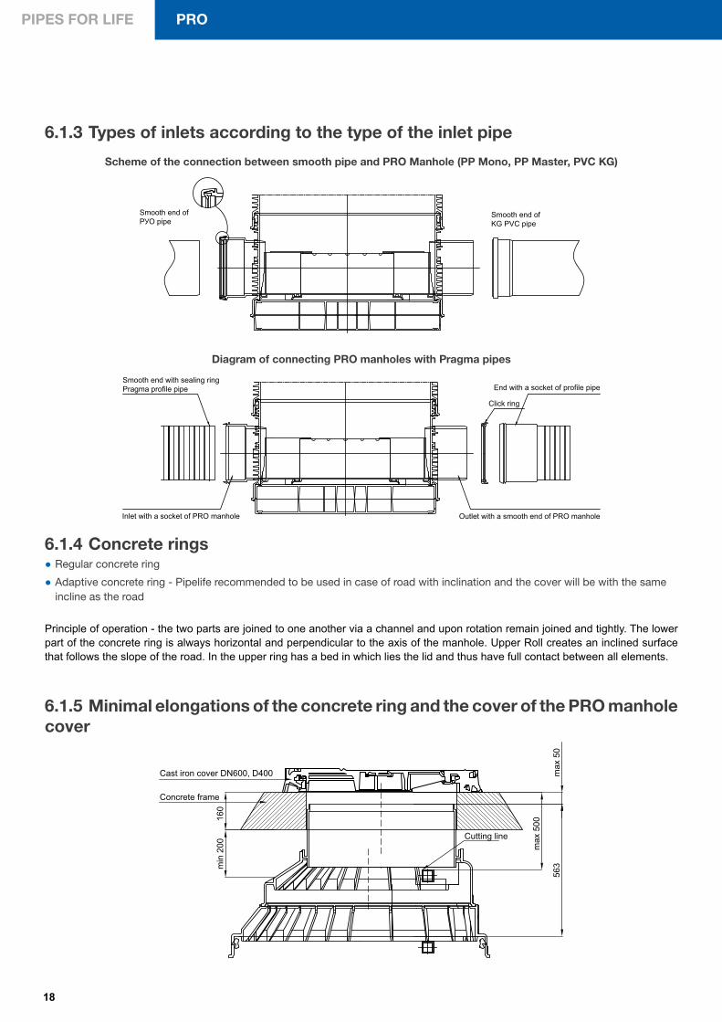
PIPES FOR LIFE PRO
Smooth end of KG PVC pipe
Smooth end of РУО pipe
Click ring
Smooth end with sealing ring Pragma profile pipe
Inlet with a socket of PRO manhole Outlet with a smooth end of PRO manhole
End with a socket of profile pipe
6.1.3 Types of inlets according to the type of the inlet pipe
Scheme of the connection between smooth pipe and PRO Manhole (PP Mono, PP Master, PVC KG)
Diagram of connecting PRO manholes with Pragma pipes
6.1.4 Concrete rings ● Regular concrete ring
● Adaptive concrete ring - Pipelife recommended to be used in case of road with inclination and the cover will be with the same incline as the road
Principle of operation - the two parts are joined to one another via a channel and upon rotation remain joined and tightly. The lower part of the concrete ring is always horizontal and perpendicular to the axis of the manhole. Upper Roll creates an inclined surface that follows the slope of the road. In the upper ring has a bed in which lies the lid and thus have full contact between all elements.
6.1.5 Minimal elongations of the concrete ring and the cover of the PRO manhole cover
563m
in 2
0016
0
max
50
max
500
Cutting line
Concrete frame
Cast iron cover DN600, D400
19
INFRASTRUCTURE SYSTEMS
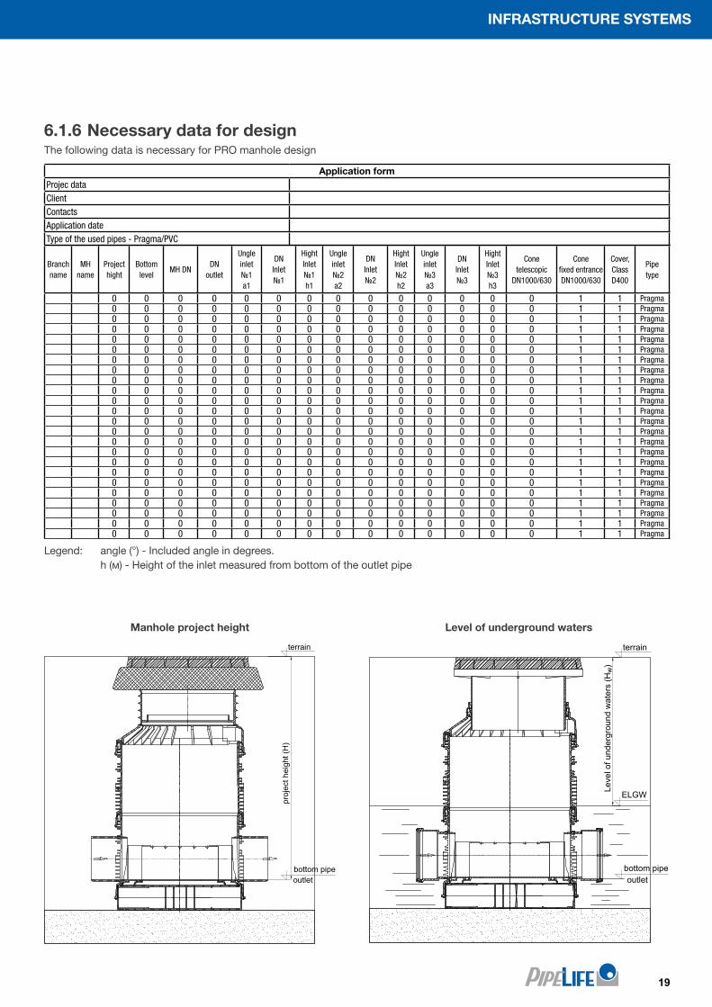
6.1.6 Necessary data for designThe following data is necessary for PRO manhole design
Manhole project height Level of underground waters
Legend: angle (°) - Included angle in degrees. h (м) - Height of the inlet measured from bottom of the outlet pipe
Branch name
MH name
Project hight
Bottomlevel
MH DNDN
outlet
Ungleinlet№1 a1
DNInlet №1
HightInlet №1 h1
Ungleinlet №2 a2
DNInlet №2
HightInlet №2 h2
Ungleinlet №3 a3
DNInlet №3
HightInlet №3 h3
Conetelescopic
DN1000/630
Conefixed entrance DN1000/630
Cover,Class D400
Pipetype
0 0 0 0 0 0 0 0 0 0 0 0 0 0 1 1 Pragma0 0 0 0 0 0 0 0 0 0 0 0 0 0 1 1 Pragma0 0 0 0 0 0 0 0 0 0 0 0 0 0 1 1 Pragma0 0 0 0 0 0 0 0 0 0 0 0 0 0 1 1 Pragma0 0 0 0 0 0 0 0 0 0 0 0 0 0 1 1 Pragma0 0 0 0 0 0 0 0 0 0 0 0 0 0 1 1 Pragma0 0 0 0 0 0 0 0 0 0 0 0 0 0 1 1 Pragma0 0 0 0 0 0 0 0 0 0 0 0 0 0 1 1 Pragma0 0 0 0 0 0 0 0 0 0 0 0 0 0 1 1 Pragma0 0 0 0 0 0 0 0 0 0 0 0 0 0 1 1 Pragma0 0 0 0 0 0 0 0 0 0 0 0 0 0 1 1 Pragma0 0 0 0 0 0 0 0 0 0 0 0 0 0 1 1 Pragma0 0 0 0 0 0 0 0 0 0 0 0 0 0 1 1 Pragma0 0 0 0 0 0 0 0 0 0 0 0 0 0 1 1 Pragma0 0 0 0 0 0 0 0 0 0 0 0 0 0 1 1 Pragma0 0 0 0 0 0 0 0 0 0 0 0 0 0 1 1 Pragma0 0 0 0 0 0 0 0 0 0 0 0 0 0 1 1 Pragma0 0 0 0 0 0 0 0 0 0 0 0 0 0 1 1 Pragma0 0 0 0 0 0 0 0 0 0 0 0 0 0 1 1 Pragma0 0 0 0 0 0 0 0 0 0 0 0 0 0 1 1 Pragma0 0 0 0 0 0 0 0 0 0 0 0 0 0 1 1 Pragma0 0 0 0 0 0 0 0 0 0 0 0 0 0 1 1 Pragma0 0 0 0 0 0 0 0 0 0 0 0 0 0 1 1 Pragma0 0 0 0 0 0 0 0 0 0 0 0 0 0 1 1 Pragma
Application formProjec dataClientContactsApplication dateType of the used pipes - Pragma/PVC
terrain
proj
ect h
eigh
t (H
)
bottom pipeoutlet
terrain
Leve
l of u
nder
grou
nd w
ater
s (H
w)
bottom pipe
ELGW
outlet
20
PIPES FOR LIFE PRO
7 REQUIREMENTS FOR LAYING
7.1 Diagrams of PRO manhole layingThe diagrams below show laying of PRO manholes with telescopic and fixed entrance in traffic zones (SLW30 and SLW60). The road surface shown is conditional and for the specific case must be taken into account part “Road infrastructure”.
Bituminous ballast 2х6 см
Crushed stone 0-75 mm
Sand bedding
Excavation bottom (well sealed soil or concrete bed)
Backfill (sealed on layers on every 20-30 см)
Bituminous layer 2x4 смCarrying layer (dense asphalt)
manhole PRO-DN800/DN1000 with telescopic entrance, SLW 30, LKW 12
manhole PRO-DN800/DN1000 with fixed entrance SLW 60
Bituminous ballast 2х6 см
Crushed stone 0-75 mm and bituminous emulsion
Sand bedding
Excavation bottom (well sealed soil or concrete bed)
Backfill (sealed on layers on every 20-30 см)
Bituminous layer 2x4 см
Bituminous layer 2x4 см
Carrying layer (dense asphalt)
21
INFRASTRUCTURE SYSTEMS
7.2 Laying of PRO manholes in case of high underground waters The PRO manholes can be laid without any danger of emerging in case of underground waters up to 2 m from the manhole bottom elevation, but for safety reasons we recommend checking with our software (see 11 from the Catalogue).
In case of underground waters higher than 2 m or when our software shows that there is a risk of emerging, Pipelife recommends the following options which eliminate the possibility of “emerging” of breaking the manhole integrity.
7.2.1 Filling the space between the shell, the base walls and the bottom of the manhole with low-slump concrete
7.2.2 External concrete of the base with the inlets and the outlet of the manholeThe stabilization of the PRO is made with watertight concrete (min. class B25) with plasticizers. The concrete must enter between manhole ribs and must be vibrated.
7.2.3 External concrete of the base with the inlets and the outlet of manhole with low-slump concrete above the underground watersThe concrete must enter between the manhole ribs and must be vibrated.
254
Double bottomSand
Concrete
Opening for pouring - Ø100
PP DN1000-17 см
Concrete – hydro resistant
Reinforcement А1 Ø8
Lower reinforcement
1310
725
123А3 N12
Low-slump concrete
ELGW100
Sand bedding100
22
PIPES FOR LIFE PRO
8 ASSEMBLY PRO - SOFTWARE 1. Pipelife software is intended to render fast and exact identification of manholes;2. The manholes are identified by manhole number, branch number and stage;3. Draws a detailed bill of quantities described item by item according to the particular manhole identification with the option of stage breakdown;4. Easy introduction of changes later on;5. Draws a bill of costs, showing dynamic updates of the pricelist;6. The identified manholes can be approved and launched for production;7. The software also includes the program Statistic PRO Calculation, which enables the operator to check if a specific manhole matches the conditions for installation.
23
INFRASTRUCTURE SYSTEMS
9 DIRECTIONS FOR LAYING AND ASSEMBLY9.1 Directions for laying and assembly of PRO-DN630, DN800 and DN10009.1.1 Preparation of the bedding layer and building of the manhole bottom
For flexible bending of the pipe at direction up to 7,5° we recommend putting of flexible Pipelife double socket +/-7,5° (see the Table). Before the pipe connection you must check the connection sealings for their proper place and cleanness. Put Pipelife grease on the ends. Put flexible double socket on the ends of the specific pipe connection until it hits the bottom. Insert the pipe to the end in the double socket.
9.1.2 Pipe connection assembly for inlet/outlet of the manhole bottom
4 5
Angle +/- 7,5°
6
Note: The images may differ from actual products.
The ballast material and the place for laying of the manhole bottom are in accordance with the regulations of EN 1610. The bedding layer must be flat and resistant to load. For this purpose a preparatory layer must be laid and compacted. Its thickness must be around 10 cm.
The ring sealing for multiple use must be put in the highest sealing canal. Check the sealing element for defects and if it is properly placed. Spread uniformly the ring-shaped sealing for multiple use with Pipelife lubricant.
Building and levelling the manhole bottom with preliminary mounted ringshape sealing for multiple uses in accordance with the pipe connections and the project instructions.
1 2 3
24
PIPES FOR LIFE PRO
9.1.5 Shortening the manhole coneThe manhole cone ends with riser with smooth walls 200 mm which can be cut maximum with 100 mm from the opening with an electric saw. The cut surface must be made flat. When the height is not enough to reach 15 cm, an additional riser with smooth walls can be added.It is not recommended the superstructure with smooth walls to exceed 30 cm.
13
9.1.4 Manhole cone mounting
Put Pipelife grease uniformly on the manhole cone.
Put the manhole cone until it hits the ring. To assure correct leveling of the ladder for climbing, you must be careful the outer alongside ribs to be in line. Put a protective cover to avoid contamination inside.
The Pipelife canal manhole is mountedand can be filled and sealed analogicallyto the mounting action of Figure 9.
10 11 12
Note: The images may differ from actual products.
9.1.3 Manhole rings mounting
Grease uniformly the ring-shaped sealing for multiple uses on the manhole ring. Put Pipelife grease uniformly also on the ring socket of the manhole.
Put the manhole ring tightly to the bottom of the manhole. To assure correct leveling of the ladder for climbing you must be careful the outer alongside ribs to be in line. Analogically to the mounting actions 7 and 8 put the other manhole rings.
Filling the hole of the manhole with filling material G1 and G2 with maximal size of the pieces 32 mm (for material with round shape) and maximal 16 mm (for material in pieces), and beating of layers with thickness of 20 to 40 cm according to EN 1610, ATV-DVWK- A 139. For street section the degree of sealing must be at least DPr = 95 %.
7 8 9
25
INFRASTRUCTURE SYSTEMS
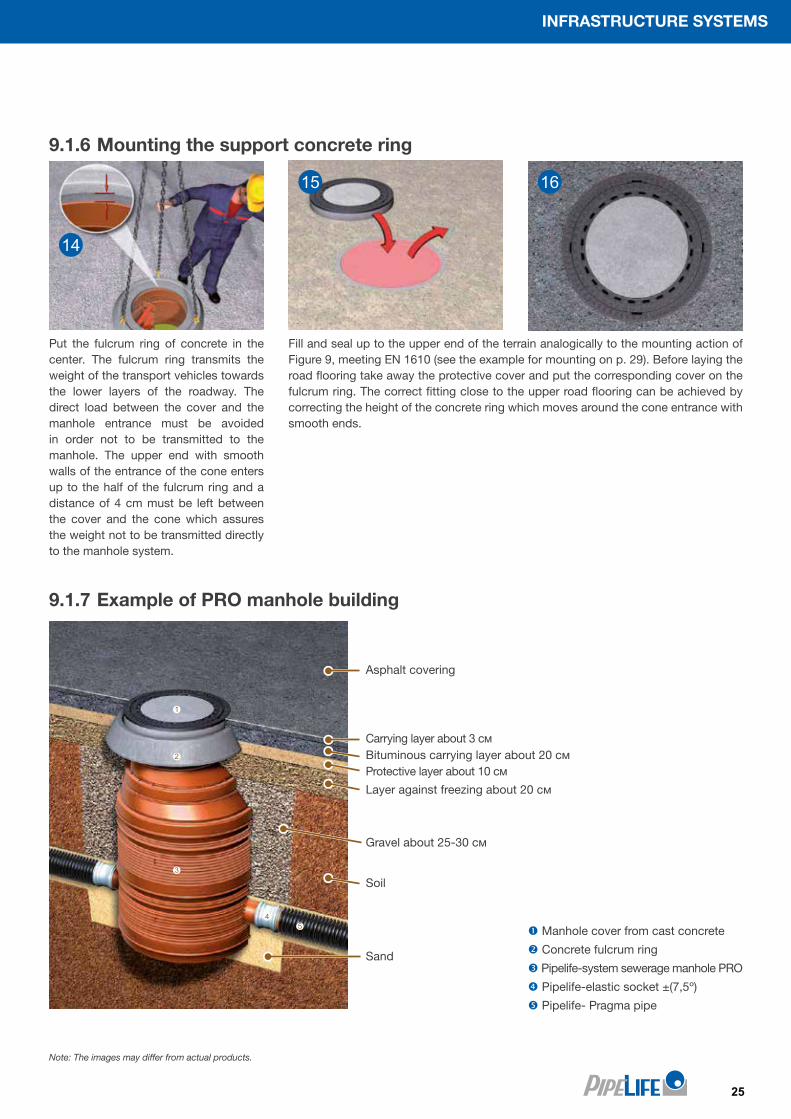
9.1.6 Mounting the support concrete ring
Fill and seal up to the upper end of the terrain analogically to the mounting action of Figure 9, meeting EN 1610 (see the example for mounting on p. 29). Before laying the road flooring take away the protective cover and put the corresponding cover on the fulcrum ring. The correct fitting close to the upper road flooring can be achieved by correcting the height of the concrete ring which moves around the cone entrance with smooth ends.
Put the fulcrum ring of concrete in the center. The fulcrum ring transmits the weight of the transport vehicles towards the lower layers of the roadway. The direct load between the cover and the manhole entrance must be avoided in order not to be transmitted to the manhole. The upper end with smooth walls of the entrance of the cone enters up to the half of the fulcrum ring and a distance of 4 cm must be left between the cover and the cone which assures the weight not to be transmitted directly to the manhole system.
15
14
16
Note: The images may differ from actual products.
9.1.7 Example of PRO manhole building
Manhole cover from cast concrete
Concrete fulcrum ring
Pipelife-system sewerage manhole PRO
Pipelife-elastic socket ±(7,5º)
Pipelife- Pragma pipe
Asphalt covering
Layer against freezing about 20 см
Sand
Soil
Gravel about 25-30 см
Protective layer about 10 см
Carrying layer about 3 смBituminous carrying layer about 20 см
26
PIPES FOR LIFE PRO
Design suggestions:
When determining the dimensions of sewer network, designers should make provisions for such a specific energy of the wastewater flow that will prevent the deposition of suspended substances along its length. For that purpose they should take into account the manhole local resistance depending on the particular type of factory made manholes. Failure to do that coupled with the presence of insufficient inclination may result in clogging of the sewer network.
Losses of about 0.04 m were recorded for invert channels in manholes DN1000 with two inlets DN315 and outlet DN315 and accordingly 90° angle of the first inlet, 180° angle of the second inlet, 0° angle of the outlet, as a result of joining
the two flows and increasing the energy of the outlet flow when the inclination is < 1%. If the inclination is higher, reliable results cannot be recorded due to the formation of a turbulent flow but anyway there is no risk of deposition of suspended substances.
Losses of about 0.03 m were recorded for invert channels in manholes DN1000 mm with three inlet pipes DN315 and one outlet pipe and accordingly 90° angle of the first inlet, 180° angle of the second inlet, 270° of the third inlet, 0° angle of the outlet, as a result of joining the three flows and increasing the energy of the outlet flow when the inclination is < 1%. If the inclination is higher, reliable results cannot be recorded due to the formation of a turbulent flow but anyway there is no risk of deposition of suspended substances.
The inclination of the bottom of invert channel does not in fact have any practical influence on head losses as compared to the head losses in invert channel whose bottom is not inclined. In such cases the changed water flow regimen should be taken into consideration in addition to the importance of ensuring sufficient specific energy for the flow that will enable it to transport the suspended substances it carries. If the feeding and the discharging pipes are of the same diameter and are used in collection chambers with two or three inlets the pipes, the pipes inside the manhole should not be connected crown to crown but the levels of feeding pipes should be adjusted to the outlet level instead.
11 HYDRAULIC CAPACITY OF PRO MANHOLESThe factors that determine the hydraulic conductivity of sewer manholes are the following: The invert channel – it has to be designed so as to ensure trouble-free conduction of the sewer flow, without leaving any “dead zones” to prevent deposit buildups. They are made of polypropylene with low roughness coefficient and are inclined to the manhole outlet.Inlets/outlets – depending on the difference of inlet and outlet diameters they are produced crown to crown to avoid rises of the water level in the manhole area due to narrowing.
The modular Pipelife sewerage manholes are delivered as a set. Each part of the manhole is designated with a number in accordance with its assembly sequence. The different parts are assembled in accordance with sequence designation. The sealings are placed inside the manhole bottom.
10 TRANSPORTATION - LOADING, UNLOADING AND STORAGE
10.1 Transport, delivery and storage
9.1.8 Important directions for safety during assembly The personnel for mounting, maintenance and repair must prove the necessary qualification for the manhole mounting.The degree of responsibility, competency and the control of the personnel must be regulated by the company which executes the project.
Norms/Directives Title
DIN 4124 Excavations and trenches - Slopes, planking and strutting, breadths of working spaces
BDS EN 1610 Construction and testing of drains and sewers
BGV C22 Construction (Personal protective equipment against falls)
BGR 117 Directives for work in tanks, silos and small spaces
Note: The images may differ from actual products.

27
INFRASTRUCTURE SYSTEMS
Out
let
DN
315
piezometers
laminar flow chamber
piezometers tested manhole
inve
rt c
hann
el
СК СК СКСК
draw tank
pressure piping DN150
pumps
СК
piezometers
laminar flow chamber
sewer pipenon-pressure flow
water supply pipe pressure flow
key:
inve
rt c
hann
el
laminar flow chamber
piezometers
DN
315
ИЗ
ХО
Д
DN
315
Out
let
DN
315
Out
let
Ø50 PEHD PN10Ø50
PE
HD
PN
10Ø16
0 P
EH
D P
N10
Ø16
0 P
EH
D P
N10
Ø160 PEHD PN10Ø160 PEHD PN10
Ø160 PEHD PN10
Ø16
0 P
EH
D P
N10
Ø16
0 P
EH
D P
N10
EXPERIMENTAL SETTING AND MEASURING TOOLS AND DEVICES
This experimental setting was designed with the purpose to test the factory made manholes of Pipelife, and the main materials, pipes, manholes, sealing, etc. were provided by the Client. The experimental setting should be satisfying the following requirements:
● to recreate a realistic reproduction of the most common hydraulic cases occurring in practice;
● to enable direct visual monitoring of the flow in different sections of the pipes and the manhole;
● to allow the conduction of experiments that could cover a comparatively wide range of changes in the main hydraulic parameters such as water amount, pipe inclination, and depth of the flow in the different sections.
Fig.9 shows the layout of experimental setting, and Fig.10 shows a picture of the ready test setting including the installed test manhole with three inlets and one outlet.
Fig. 10
Fig. 9
Note: The images may differ from actual products.
28
PIPES FOR LIFE PRO
TEST REPORT
On the hydraulic test study of polypropylene manholes manufactured by Pipelife Bulgaria.
ORDERING ORGANIZATION: PIPELIFE BULGARIA EOOD, Company ID Code 115944768, 3 Industrialna Street, Botevgrad Town
PERFORMED BY: UNIVERSITY OF ARCHITECTURE, CIVIL ENGINEERING AND GEODESY – CENTER OF RESEARCH STUDIES AND DESIGNS /UACEG-CRSD/ in Sofia, 1 Hristo Smirnenski Blvd.
Team of Researchers: Project Manager: …………………….. Assoc. Prof. Engineer Dimitar Alichkov 1. ……………………………. Chief Prof. Assistant Engineer Tanya Igneva-Danova
2. ……………………………. Chief Prof. Assistant Engineer Emil Tsanov
3. ……………………………. Prof. Assistant Engineer Borislav Indzhov
April 2016 Sofia
1 Hristo Smirnenski Blvd, Sofia 1046, Republic of Bulgaria
Telephone: (02) 963-52-45; Fax: (02) 865 68 63
Test Report: Hydraulic test study of polypropylene manholes manufactured by Pipelife Bulgaria
29
INFRASTRUCTURE SYSTEMS
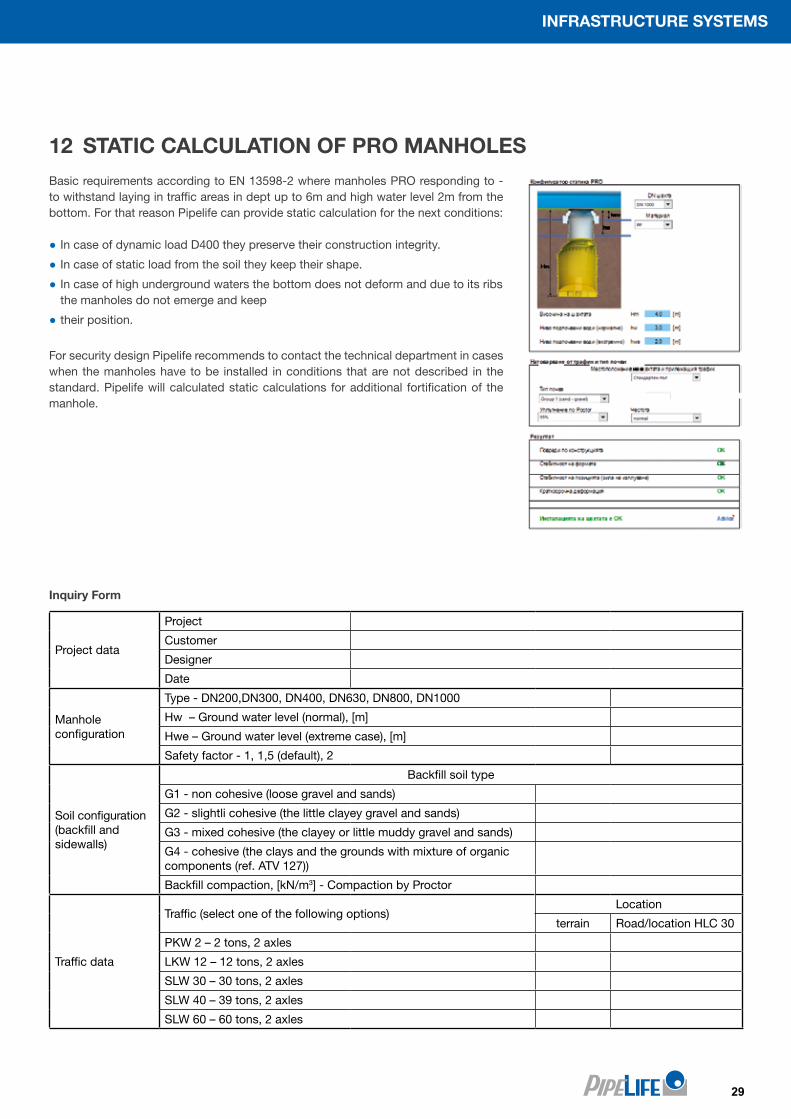
Basic requirements according to EN 13598-2 where manholes PRO responding to - to withstand laying in traffic areas in dept up to 6m and high water level 2m from the bottom. For that reason Pipelife can provide static calculation for the next conditions:
● In case of dynamic load D400 they preserve their construction integrity.
● In case of static load from the soil they keep their shape.
● In case of high underground waters the bottom does not deform and due to its ribs the manholes do not emerge and keep
● their position.
For security design Pipelife recommends to contact the technical department in cases when the manholes have to be installed in conditions that are not described in the standard. Pipelife will calculated static calculations for additional fortification of the manhole.
12 STATIC CALCULATION OF PRO MANHOLES
Project data
Project
Customer
Designer
Date
Manhole configuration
Type - DN200,DN300, DN400, DN630, DN800, DN1000
Hw – Ground water level (normal), [m]
Hwe – Ground water level (extreme case), [m]
Safety factor - 1, 1,5 (default), 2
Soil configuration (backfill and sidewalls)
Backfill soil type
G1 - non cohesive (loose gravel and sands)
G2 - slightli cohesive (the little clayey gravel and sands)
G3 - mixed cohesive (the clayey or little muddy gravel and sands)
G4 - cohesive (the clays and the grounds with mixture of organic components (ref. ATV 127))
Backfill compaction, [kN/m3] - Compaction by Proctor
Traffic data
Traffic (select one of the following options)Location
terrain Road/location HLC 30
PKW 2 – 2 tons, 2 axles
LKW 12 – 12 tons, 2 axles
SLW 30 – 30 tons, 2 axles
SLW 40 – 39 tons, 2 axles
SLW 60 – 60 tons, 2 axles
Inquiry Form
30
PIPES FOR LIFE PRO
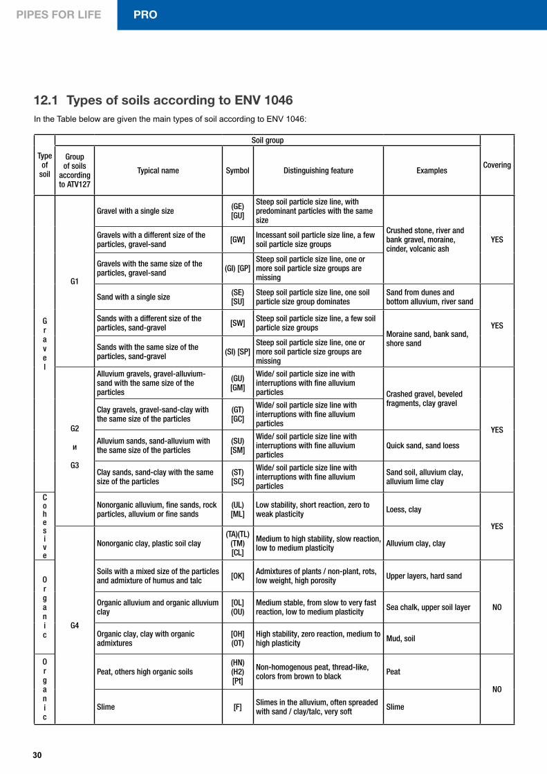
12.1 Types of soils according to ENV 1046In the Table below are given the main types of soil according to ENV 1046:
Type of
soil
Soil group
CoveringGroup of soils
according to ATV127
Typical name Symbol Distinguishing feature Examples
Gravel
G1
Gravel with a single size (GE) [GU]
Steep soil particle size line, with predominant particles with the same size
Crushed stone, river and bank gravel, moraine, cinder, volcanic ash
YESGravels with a different size of the particles, gravel-sand [GW] Incessant soil particle size line, a few
soil particle size groups
Gravels with the same size of the particles, gravel-sand (GI) [GP]
Steep soil particle size line, one or more soil particle size groups are missing
Sand with a single size (SE) [SU]
Steep soil particle size line, one soil particle size group dominates
Sand from dunes and bottom alluvium, river sand
YESSands with a different size of the particles, sand-gravel [SW] Steep soil particle size line, a few soil
particle size groupsMoraine sand, bank sand, shore sand Sands with the same size of the
particles, sand-gravel (SI) [SP]Steep soil particle size line, one or more soil particle size groups are missing
G2
и
G3
Alluvium gravels, gravel-alluvium-sand with the same size of the particles
(GU) [GM]
Wide/ soil particle size ine with interruptions with fine alluvium particles Crashed gravel, beveled
fragments, clay gravel
YES
Clay gravels, gravel-sand-clay with the same size of the particles
(GT) [GC]
Wide/ soil particle size line with interruptions with fine alluvium particles
Alluvium sands, sand-alluvium with the same size of the particles
(SU) [SM]
Wide/ soil particle size line with interruptions with fine alluvium particles
Quick sand, sand loess
Clay sands, sand-clay with the same size of the particles
(ST) [SC]
Wide/ soil particle size line with interruptions with fine alluvium particles
Sand soil, alluvium clay, alluvium lime clay
Cohesive
Nonorganic alluvium, fine sands, rock particles, alluvium or fine sands
(UL) [ML]
Low stability, short reaction, zero to weak plasticity Loess, clay
YES
G4
Nonorganic clay, plastic soil clay(TA)(TL)
(TM)[CL]
Medium to high stability, slow reaction, low to medium plasticity Alluvium clay, clay
Organic
Soils with a mixed size of the particles and admixture of humus and talc [OK] Admixtures of plants / non-plant, rots,
low weight, high porosity Upper layers, hard sand
NOOrganic alluvium and organic alluvium clay
[OL](OU)
Medium stable, from slow to very fast reaction, low to medium plasticity Sea chalk, upper soil layer
Organic clay, clay with organic admixtures
[OH](OT)
High stability, zero reaction, medium to high plasticity Mud, soil
Organic
Peat, others high organic soils (HN)(H2)[Pt]
Non-homogenous peat, thread-like, colors from brown to black Peat
NO
Slime [F] Slimes in the alluvium, often spreaded with sand / clay/talc, very soft Slime
31
INFRASTRUCTURE SYSTEMS
В таблицата по-долу са показани различните методи на уплътняване за постигане на необходимия коефициент по Proctor:
12.2 Compaction of the material for backfill
The requirements for the degree of compaction depend on the general load and must be defined in the project documentation. The compaction must be done by different types of compacting. Depending on the equipment, the layers’ thickness and the soil susceptibility to compaction, different degrees of compaction can be achieved. In Table 3.2 are given different data which refer to gravel, clay and alluvium soils.
Table 3 Compaction methods
* Before using compaction tools** Compaction on both pipe sides
13 QUALITY MARK BY THE BULGARIAN WATER ASSOCIATIONThe Bulgarian Water Association launched the initiative entitled “Bulgarian Water Association Quality Mark” to reas-sure the confidence in every manufactur-er pretending to be supplying products that meet the standard requirements.
The presence of “Bulgarian Water As-sociation Quality Mark” on manufac-tured products guarantees that the raw materials used for their produc-tion are of proven high quality and meet the manufacturing standards.
The control of materials is exercised by random inspections and the sample taken are tested in accredited laborato-ries. The inspections are carried out in strictly defined order and the exercise of full control throughout the test.
Manholes and inspection chambers according to BDS EN 13598-2:2016
№ Name of indicator Number and size of tested samplesFrequency of testing procedures
1.
Appearance, color Dimensions (geometry), p.6.1; p.6.2.- diameter and length of socketed/smooth tip - wall thickness of the body, of socketed/smooth tip- of the base (bottom), p.6.3. - external/internal diameter of the body and the individual sections (modules) - internal dimensions - of socketed/smooth tips of the inlet and the outlet
1 pc. of fully equipped manhole with modules twice a year
2.
Physical properties – of the body and/or the individual sections (modules) of the manholes, p.8, Table 5 and Schedule A, B
twice a yearMelt flow index by weight (MFR)Density Polymer type identification
3.
Mechanical properties, p.7, Table 3.4 twice a year
Shock resistance/strength at (23±1)°C of the base, Table 3
Ring hardness of the individual sections (modules), Table 4 3 pc. of tested samples, L=(300÷1000) mm from sections (modules) twice a year
Resistance/strength to vertical loading on stairs, Table 4 1 pc. of step of the stairs twice a year
5.
Requirements for system operation, p.9, Table 6
Water-tightness (water impermeability) of the system at (23±5)°C1 manhole system (base, 1 module, cover and frame) and 2 socketed pipes, L=1.0 m, for connecting the base inlet and outlet
twice a year
Water-tightness of the system with elastomer sealing rings (diametrical or angular deflection) of the pipe connecting fittings
1 system of flexible pipes and fittings for horizontal connection by sockets to the manhole base and cover
twice a year
COMPACTION METHODS
Equipment Weight[kg]
Maximal thickness of the layer before
compaction [m]
Minimal thickness
of the initial backfill
above the pipe [m]*
Number of repetitions for achieving the compaction
gravel,sand
clay,alluvium
85%according to Proctor
modified test
90%according to Proctor
modified test
95%according to Proctor
modified test
Fine stuffing - 0.10 - - 1 3 6
Manual compaction min. 15 0.15 0.10 0.30 1 3 6
Vibration compaction 50-100 0.30 0.20-0.25 0.50 1 3 6
Distributed mechanized compaction**
50-100 0,20 - 0.50 1 4 7
Mechanized compaction
50-100100-200400-600
--
0.20
0.500.400.80
111
444
777

PRO
■ Production / central warehouse
2140, Industrialna street 3
www.pipelife.bg
■ Warehouse Burgas
South industrial zone
tel/fax: 056/ 509 129 e-mail: [email protected]
■ Warehouse Sofia
Boicho Boichev street 82
tel/fax: 02/ 957 86 08 e-mail: [email protected]