
INITIAL INSTALLATION PROCEDURES 4
51
BT Pathway Installation and Maintenance manual Version 2 April 2003 1 INTRODUCTION ....................................................................................................................... 3 GENERAL OVERVIEW ................................................................................................................ 3 SAFETY AND PRECAUTIONS....................................................................................................... 3 Safety precautions and switch-on ...................................................................................... 3 Electrostatic precaution (ESP) ........................................................................................... 3 INITIAL INSTALLATION PROCEDURES ................................................................................ 4 INSTALLING THE CCU ............................................................................................................ 7 LOCATION FOR CENTRAL CONTROL UNIT (CCU) ........................................................................ 7 MOUNTING THE CCU................................................................................................................ 7 CCU Mounting bracket ....................................................................................................... 8 SECURING THE CCU TO THE WALL .......................................................................................... 10 BASE MOTHER BOARD............................................................................................................ 11 SYSTEM MODULES AND EXPANSION CARDS.............................................................................. 12 EXTENSION EXPANSION CARD ................................................................................................. 13 Extension expansion board column support .................................................................... 14 Allowed extension expansion card locations ................................................................... 14 PSTN EXPANSION CARD ........................................................................................................ 15 Allowed PSTN Expansion card locations ......................................................................... 16 ISDN CLOCKING CARD............................................................................................................ 17 ISDN clocking card (upgrade module) location................................................................ 18 ISDN2 CARD (BRI) ................................................................................................................ 19 Allowed locations of ISDN expansion card ...................................................................... 20 SYSTEM ISDN SETTINGS ........................................................................................................ 21 Terminating resistors ........................................................................................................ 21 BASE MOTHERBOARD CONNECTIONS ....................................................................................... 21 EXPANSION BOARD CONNECTIONS........................................................................................... 22 VOICE MAIL............................................................................................................................ 24 V24/SMDR SERIAL PORT....................................................................................................... 25 External serial port cable and connectors ........................................................................ 26 External serial port Pin-out ............................................................................................... 27 DOOR INTERCOM.................................................................................................................... 28 REPLACEMENT OF SYSTEM PRINTED CIRCUIT BOARD (PCB) MODULES ..................................... 29 POWER SUPPLY...................................................................................................................... 29 Replacing a power supply unit ..................................................................................... 30 CAUTION ............................................................................................................................. 30 INSTALLING THE BATTERY BACK-UP.......................................................................................... 31 Mounting the Battery Backup unit ................................................................................ 33 EXTENSION PORT (22)............................................................................................................ 34 CENTRAL BELL ....................................................................................................................... 34 DOORSTRIKE.......................................................................................................................... 34 GENERAL CABLING AND WIRING INFORMATION............................................................ 35 MDF WIRING TECHNIQUE ....................................................................................................... 36 SYSTEMPHONE ..................................................................................................................... 38 FEATURE PHONE CONNECTIONS.............................................................................................. 38 PLACING THE SYSTEMPHONE ON A DESK TOP ........................................................................... 39 WALL MOUNTING A SYSTEMPHONE .......................................................................................... 40 POWER FAIL ........................................................................................................................... 40 PSTN ................................................................................................................................ 40
Transcript of INITIAL INSTALLATION PROCEDURES 4

BT Pathway Installation and Maintenance manual
Version 2 April 2003 1
INTRODUCTION ....................................................................................................................... 3GENERAL OVERVIEW ................................................................................................................ 3SAFETY AND PRECAUTIONS....................................................................................................... 3
Safety precautions and switch-on ...................................................................................... 3Electrostatic precaution (ESP) ........................................................................................... 3
INITIAL INSTALLATION PROCEDURES ................................................................................ 4
INSTALLING THE CCU ............................................................................................................ 7LOCATION FOR CENTRAL CONTROL UNIT (CCU)........................................................................ 7MOUNTING THE CCU................................................................................................................ 7
CCU Mounting bracket ....................................................................................................... 8SECURING THE CCU TO THE WALL .......................................................................................... 10BASE MOTHER BOARD............................................................................................................ 11SYSTEM MODULES AND EXPANSION CARDS.............................................................................. 12EXTENSION EXPANSION CARD ................................................................................................. 13
Extension expansion board column support .................................................................... 14Allowed extension expansion card locations ................................................................... 14
PSTN EXPANSION CARD ........................................................................................................ 15Allowed PSTN Expansion card locations......................................................................... 16
ISDN CLOCKING CARD............................................................................................................ 17ISDN clocking card (upgrade module) location................................................................ 18
ISDN2 CARD (BRI) ................................................................................................................ 19Allowed locations of ISDN expansion card ...................................................................... 20
SYSTEM ISDN SETTINGS ........................................................................................................ 21Terminating resistors........................................................................................................ 21
BASE MOTHERBOARD CONNECTIONS ....................................................................................... 21EXPANSION BOARD CONNECTIONS........................................................................................... 22VOICE MAIL............................................................................................................................ 24V24/SMDR SERIAL PORT....................................................................................................... 25
External serial port cable and connectors........................................................................ 26External serial port Pin-out ............................................................................................... 27
DOOR INTERCOM.................................................................................................................... 28REPLACEMENT OF SYSTEM PRINTED CIRCUIT BOARD (PCB) MODULES ..................................... 29POWER SUPPLY...................................................................................................................... 29
Replacing a power supply unit ..................................................................................... 30CAUTION............................................................................................................................. 30INSTALLING THE BATTERY BACK-UP.......................................................................................... 31
Mounting the Battery Backup unit................................................................................ 33EXTENSION PORT (22)............................................................................................................ 34CENTRAL BELL....................................................................................................................... 34DOORSTRIKE.......................................................................................................................... 34
GENERAL CABLING AND WIRING INFORMATION............................................................ 35MDF WIRING TECHNIQUE ....................................................................................................... 36
SYSTEMPHONE ..................................................................................................................... 38FEATURE PHONE CONNECTIONS.............................................................................................. 38PLACING THE SYSTEMPHONE ON A DESK TOP........................................................................... 39WALL MOUNTING A SYSTEMPHONE .......................................................................................... 40POWER FAIL ........................................................................................................................... 40
PSTN ................................................................................................................................ 40

BT Pathway Installation and Maintenance manual
Version 2 April 2003 2
CONNECTING TO THE NETWORK ...................................................................................... 41ANALOGUE/PSTN LINES......................................................................................................... 41206 LINE TERMINATION........................................................................................................... 41412 LINE TERMINATION........................................................................................................... 42ISDN LINES........................................................................................................................... 43
S-Bus terminating socket ................................................................................................. 441 T0& Optional S0 fitted ................................................................................................... 44
INSTALLATION COMPLETION & POWER UP..................................................................... 44REFITTING THE CCU COVER .................................................................................................. 45
COMMISSIONING................................................................................................................... 46
RECOMMENDATIONS FOR CUSTOMER TRAINING.......................................................... 47
TROUBLESHOOTING............................................................................................................ 47
TECHNICAL SPECIFICATION............................................................................................... 48
CONFIGURATION TABLE ..................................................................................................... 50POWER & ENVIRONMENTAL REQUIREMENTS........................................................................... 51

BT Pathway Installation and Maintenance manual
Version 2 April 2003 3
IntroductionThis document describes the practices to be adopted by field engineers during installationand maintenance of BT Pathway. A more detailed description of the product, along withcustomer programmable facilities and features, may be found in the Owner’s Manual, whichshould be read in conjunction with this document.
General overview• The BT Pathway is a hybrid PABX / key system, which may be equipped with a
Systemphone, or approved 2-wire apparatus.• The BT Pathway is modular in construction and can be upgraded by adding various
system expansion modules• The BT Pathway allows connection to ISDN 2 and analogue MF or LD exchange lines.• The BT Pathway may be configured with one or two internal S-Bus interfaces for
connection to approved ISDN apparatus.• The BT Pathway is a versatile easy to use system which is easy to install and maintain
Safety and Precautions
Safety precautions and switch-on After installing the CCU and all cabling, ensure that the following points are checked beforeswitching the mains power on: • The mains socket outlet shall be installed near the equipment and shall be easily
accessible.• There is a reliable earth at the mains supply socket, earth pin.• The cabled extensions have a telephone or Systemphone connected.• The CCU PCB cover has been replaced, if it was previously removed.• Switch on the mains power and allow at least eight seconds for the CCU to go through its
power up routine.
Electrostatic precaution (ESP) The BT Pathway contains electrostatic sensitive components. To ensure long term reliabilityof the system, electrostatic precautions should be taken when handling any of the systemmodule-PCBs. A connector is provided on the MDF for connection of ESP straps. If a functional earth is connected to the system it can be used for electrostatic precautions(ESP). CAUTION The mains protective earth should not be used for electrostatic precautions (ESP)
BT Pathway Installation and Maintenance manual
Version 2 April 2003 4
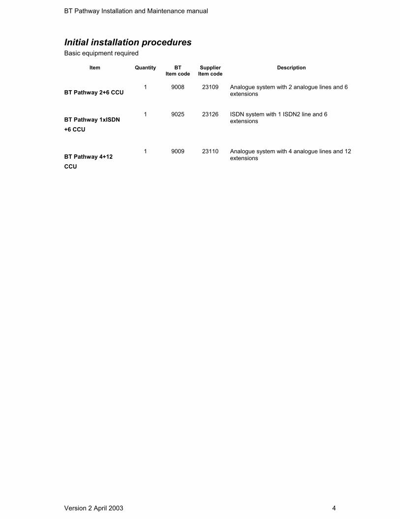
Initial installation procedures Basic equipment required
Item Quantity BT Item code
Supplier Item code
Description
BT Pathway 2+6 CCU
1
9008
23109
Analogue system with 2 analogue lines and 6extensions
BT Pathway 1xISDN+6 CCU
1
9025
23126
ISDN system with 1 ISDN2 line and 6extensions
BT Pathway 4+12CCU
1
9009
23110
Analogue system with 4 analogue lines and 12extensions
BT Pathway Installation and Maintenance manual
Version 2 April 2003 5
Individual ItemDescription
Max. No
per system
BT Item
code
Supplier Item code
Description
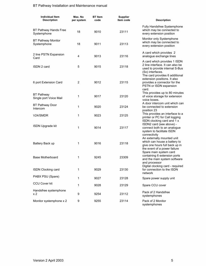
BT Pathway Hands FreeSystemphone
18
9010
23111
Fully Handsfree Systemphonewhich may be connected toevery extension position
BT Pathway MonitorSystemphone
18
9011
23113
Monitor only Systemphonewhich may be connected toevery extension position
2 line PSTN ExpansionCard
4
9013
23116
A card which provides 2analogue exchange lines
ISDN 2 card 5 9015 23118
A card which provides 1 ISDN2 line interface. It can also beused to provide internal S-Bus(So) interfaces.
6 port Extension Card 2 9012 23115
The card provides 6 additionalextension positions. It alsoprovides a connector for thePSTN or ISDN expansioncard.
BT Pathway Single port Voice Mail 1 9017 23120
This provides up to 80 minutesof voice storage for extensionvoice boxes.
BT Pathway DoorIntercom 1 9020 23124
A door intercom unit which canbe connected to extensionposition 23
V24/SMDR 1 9023 23125 This provides an interface to aprinter or PC for Call logging
ISDN Upgrade kit 1 9014 23117
ISDN clocking card and 1 xISDN2 card (see above) -connect both to an analoguesystem to facilitate ISDNconnectivity
Battery Back up 1 9016 23118
An externally mounted unitwhich can house a battery togive one hours full back up inthe event of a power failure
Base Motherboard 1 9245 23309
Spare main system cardcontaining 6 extension portsand the main system softwareand processor
ISDN Clocking card 1 9029 23130 Digital clocking card - requiredfor connection to the ISDNnetwork
PABX PSU (Spare) 1 9027 23128 Spare power supply unit
CCU Cover kit 1 9028 23129 Spare CCU cover
Handsfree systemphonex 2
9 9254 23112 Pack of 2 Handsfreesystemphones
Monitor systemphone x 2
9 9255 23114 Pack of 2 Monitorsystemphones

BT Pathway Installation and Maintenance manual
Version 2 April 2003 6
Apparatus approved for connection to the
BT Pathway
Asrequired
Description
Master line jack unitswithout GDTs
1 perextension
and Centralbell
6 wire 0.5 mm cable As required
BT 80A or similar
Doorstrikeand PublicAddress
(PA)systems
Doorstrike and PA Not availablefrom BT

BT Pathway Installation and Maintenance manual
Version 2 April 2003 7
Installing the CCU
Location for Central Control Unit (CCU) The CCU is intended for installation in a residential or office-type environment. It needs to bemounted at a convenient working height on a dry flat wall. The normal height is 1 metre fromthe floor to the bottom of the CCU case.
Allow at least 100 mm of free space all around the CCU for ventilation and 310 mm to theright or underneath the CCU for the addition of the Battery Back up unit. The CCU needs to be within approximately two metres of a dedicated AC mains powersupply outlet. The CCU must not share the same mains supply socket with any otherelectrical appliance.
Mounting the CCU When a suitable location has been found, mark the screw locations on the mounting surfaceusing the mounting bracket provided. If the CCU is to be mounted on masonry or plaster board suitable wall plugs must be used.Drill and plug four holes in the wall at the marked locations. The holes should be deepenough to accept a 2.5cm/1 inch screw.
CAUTION Do not site the CCU where it will be subjected to excessive levels of heat, dust damp or highhumidity. Locating the equipment near sources of electromagnetic radiation such as heavyelectrical switchgear, lift machinery or electric arc welders should be specifically avoided.
BT Pathway Installation and Maintenance manual
Version 2 April 2003 8
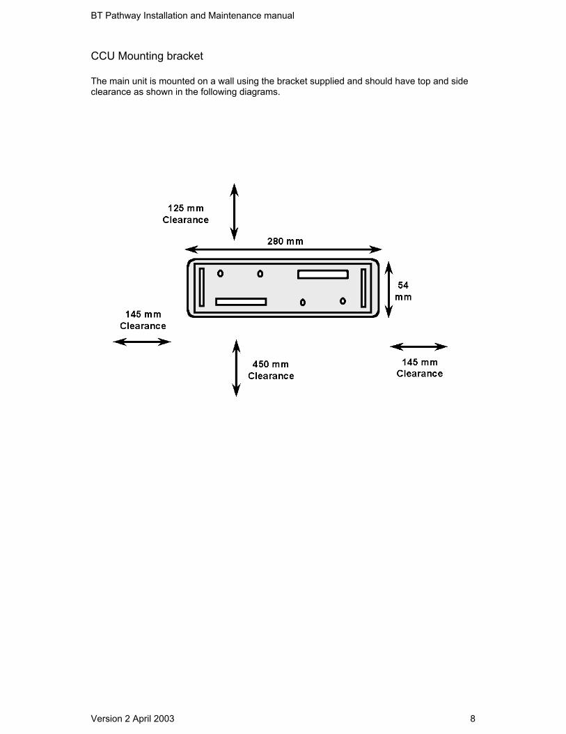
CCU Mounting bracket
The main unit is mounted on a wall using the bracket supplied and should have top and sideclearance as shown in the following diagrams.

BT Pathway Installation and Maintenance manual
Version 2 April 2003 9
Locate the CCUonto the wall-mounting bracket
Slide the MDF cover off by moving it upwards by sliding it down into position
BT Pathway
Remove the MDF cover Connect the system to the mains supply retaining screw.
BT Pathway Installation and Maintenance manual
Version 2 April 2003 10
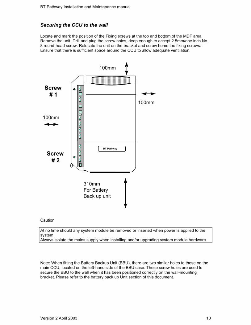
Securing the CCU to the wall Locate and mark the position of the Fixing screws at the top and bottom of the MDF area.Remove the unit. Drill and plug the screw holes, deep enough to accept 2.5mm/one inch No.8 round-head screw. Relocate the unit on the bracket and screw home the fixing screws.Ensure that there is sufficient space around the CCU to allow adequate ventilation.
100mm
BT Pathway
100mm
310mmFor BatteryBack up unit
100mm
Screw# 1
Screw# 2
Caution At no time should any system module be removed or inserted when power is applied to thesystem. Always isolate the mains supply when installing and/or upgrading system module hardware
Note: When fitting the Battery Backup Unit (BBU), there are two similar holes to those on themain CCU, located on the left-hand side of the BBU case. These screw holes are used tosecure the BBU to the wall when it has been positioned correctly on the wall-mountingbracket. Please refer to the battery back up Unit section of this document.
BT Pathway Installation and Maintenance manual
Version 2 April 2003 11
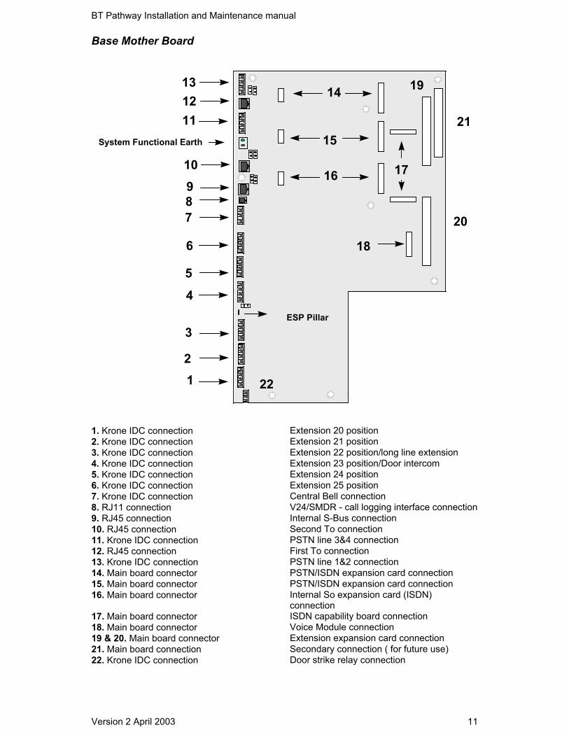
Base Mother Board
12
3
45
6
78910
111213
14
16
15
17
18
19
20
21
22
ESP Pillar
System Functional Earth
1. Krone IDC connection Extension 20 position 2. Krone IDC connection Extension 21 position 3. Krone IDC connection Extension 22 position/long line extension 4. Krone IDC connection Extension 23 position/Door intercom 5. Krone IDC connection Extension 24 position 6. Krone IDC connection Extension 25 position 7. Krone IDC connection Central Bell connection 8. RJ11 connection V24/SMDR - call logging interface connection 9. RJ45 connection Internal S-Bus connection 10. RJ45 connection Second To connection 11. Krone IDC connection PSTN line 3&4 connection 12. RJ45 connection First To connection 13. Krone IDC connection PSTN line 1&2 connection 14. Main board connector PSTN/ISDN expansion card connection 15. Main board connector PSTN/ISDN expansion card connection 16. Main board connector Internal So expansion card (ISDN)
connection 17. Main board connector ISDN capability board connection 18. Main board connector Voice Module connection 19 & 20. Main board connector Extension expansion card connection 21. Main board connection Secondary connection ( for future use) 22. Krone IDC connection Door strike relay connection

BT Pathway Installation and Maintenance manual
Version 2 April 2003 12
System Modules and expansion cards
There are a number of modules, which can be installed onto the Base Mother Board:• Extension expansion card. This provides six extensions and a connector for a network
expansion card, ISDN or analogue.
• PSTN expansion card. This card provides two analogue exchange lines.
• ISDN Expansion card. This card provides one ISDN2 interface. The same card is used forthe network T0 and the internal S bus. Links located on the card must be relocated tochange the interface from T0 to S bus operation.
• Voice module-single channel. Only one of these modules can be inserted in a unit. Bothprovide up to 80 minutes voice storage. When equipped each extension can be providedwith a voice box. A minimum of two minutes storage is allocated automatically to eachprogrammed extension. The remaining capacity is dynamically allocated.

BT Pathway Installation and Maintenance manual
Version 2 April 2003 13
Extension expansion card
1
2
3
4
5
6
7
89
12345678
Plan view
Side view
230mm
142mm
10
11
1011
1. Krone IDC connection First Extension position2. Krone IDC connection Second Extension position3. Krone IDC connection Third Extension position4. Krone IDC connection Fourth Extension position5. Krone IDC connection Fifth Extension position6. Krone IDC connection Sixth Extension position7. Krone IDC connection PSTN line connector ( Supports 2 lines)8. RJ45 connection ISDN connector9. Interface socket ISDN/PSTN expansion module position10. Screw terminal connector Functional Earth connector11. Jumper straps ISDN So/To option select

BT Pathway Installation and Maintenance manual
Version 2 April 2003 14
Extension expansion board column support
Ensure the Extension expansion card is fitted with the column support located under the linetermination points.
Allowed extension expansion card locations

BT Pathway Installation and Maintenance manual
Version 2 April 2003 15
PSTN Expansion card
NOTE:This card allows the BT Pathway to utilise two analogue trunk lines. Unless this card is fittedno analogue line access is possible when using the switch. There are no single line cardsavailable on the BT Pathway. When only one line is in use the second line must be disabledusing system programming.
A
TOPInsertthis way
ETAL
ETAL
Locate PSTN expansion card into connector 14,15 or onconnector 9 on extension expansion card
1 2
155mm
57mm

BT Pathway Installation and Maintenance manual
Version 2 April 2003 16
Allowed PSTN Expansion card locations
Locate PSTN cardhere
Locate PSTN cardhere
Locate PSTN cardhere
Locate PSTN cardhere
BT Pathway Installation and Maintenance manual
Version 2 April 2003 17
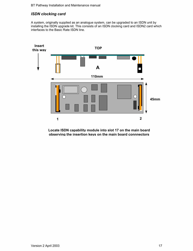
ISDN clocking card
A system, originally supplied as an analogue system, can be upgraded to an ISDN unit byinstalling the ISDN upgrade kit. This consists of an ISDN clocking card and ISDN2 card whichinterfaces to the Basic Rate ISDN line.
A
TOPInsertthis way
Locate ISDN capability module into slot 17 on the main boardobserving the insertion keys on the main board connnectors
1 2
45mm
110mm
BT Pathway Installation and Maintenance manual
Version 2 April 2003 18
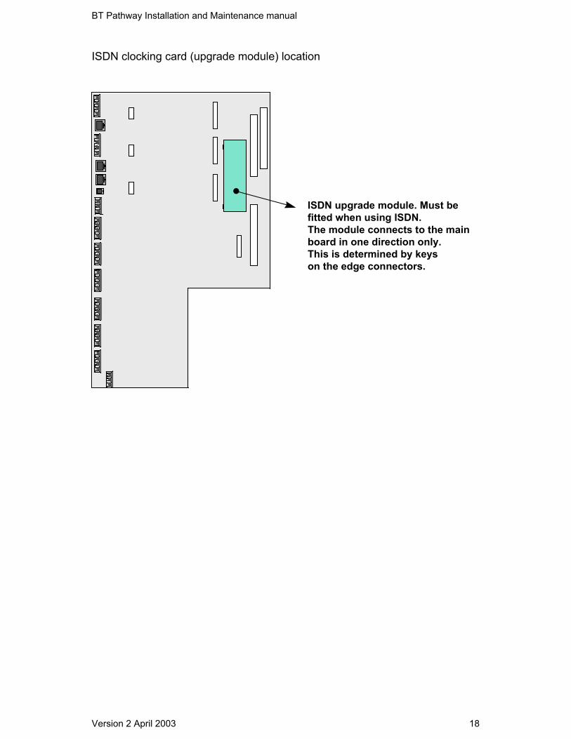
ISDN clocking card (upgrade module) location
ISDN upgrade module. Must befitted when using ISDN. The module connects to the mainboard in one direction only.This is determined by keyson the edge connectors.

BT Pathway Installation and Maintenance manual
Version 2 April 2003 19
ISDN2 card (BRI)
A
TOPInsertthis way
ETAL
ETAL
Boardident
Locate ISDN expansion card into connector 14,15 or 16 or onconnector 9 on extension expansion card
1 2
135mm
57mm

BT Pathway Installation and Maintenance manual
Version 2 April 2003 20
Allowed locations of ISDN expansion card
Locate ISDN cardhere
ISDN Clockingcard. Must befitted to the mainboard when usingISDN networkfeatures
Locate ISDN cardhere
Locate ISDN cardhere
Locate ISDN cardhere
Locate ISDN cardhere

BT Pathway Installation and Maintenance manual
Version 2 April 2003 21
System ISDN settings
The system can be configured with five ISDN interfaces. Two of these can be configured forinternal So operation. The So interfaces provide ISDN to-the -desk, allowing users send voiceand data information over the ISDN network.
Terminating resistors
The ISDN interfaces on the base motherboard are fixed. Connectors 10 and 12 are fornetwork interfaces (T0) and location 9 is for an internal S-Bus (So Interface). Each of the T and Sinterface connectors has two jumpers JP-A, JP-B and JP-C (see diagram below).
These are used to insert or remove a 100-ohm termination resistor from each of theinterfaces. Inserting the jumpers terminates the line with 100 Ohms. The unit is delivered withthe jumpers connected across the two pins (the 100-ohm termination provided)
In normal operation the NTE provides termination on one end of the S-Bus. Consequently theSo interface must always have the terminating resistor JP-C connected (the So interfaceemulates the NTE).
In situations where the BT Pathway is not required to provide the S-Bus 100 ohm terminationon the To interfaces, the jumpers JP-A and JP-B may be removed. It is recommended the linkbe inserted on one of the pins to ensure it is not lost.
Base motherboard connections
11 10 9 813 12
JP-A JP-CJP-B
The base motherboard provides the default So slot (slot 16 - See the base mother boarddescription in this manual). As the system can provide two So interfaces, the second So canbe provided by an ISDN interface card connected to either of the extension expansionboards.
Only one of the extension expansion cards can be set for So operation

BT Pathway Installation and Maintenance manual
Version 2 April 2003 22
Expansion board connectionsThere are two sets of four jumpers on the extension expansion card, which provide ISDN/S-Bus set-up options when the ISDN expansion card is connected into slot 9.
The four jumpers at the back of the RJ45 connector (J1, J3, J4 and J2) must be moved to theS position for So operation. In default, the jumpers are set in the T position for To operation.
When changing the jumper settings from the default position, the system must also beprogrammed from T to S operation. See the owner’s manual or Camino for programmingdetails.
There are 4 jumpers beside the RJ45 connector. JP-2 and JP-1 are the 100-ohm terminatingresistors (connected in default mode).
The expansion board ISDN interface can provide a 40Volt supply to connected ISDN devices.Up to 4 devices (maximum) can be powered by this 40Volt supply, on each S-Bus. The optionto provide or remove this voltage supply is available on the extension expansion board byinserting or removing jumpers. Please see the following diagram.
To/So Select
JP4 JP3 JP1 JP2
J1
J3
J4
J2TS
Position A
Position B

BT Pathway Installation and Maintenance manual
Version 2 April 2003 23
JP-1Terminating
Resistor
JP-2Terminating
Resistor
JP-3ISDN So 40V
Supply
JP-4ISDN So 40V
Supply
Position A 100 Ohm out 100 Ohm out No So 40V No So 40V
Position B 100 Ohm in 100 Ohm in 40V supplied 40V supplied
For J1 to J4 - Move all the Jumpers to the T position for To operation and to the S position forSo operation

BT Pathway Installation and Maintenance manual
Version 2 April 2003 24
Voice Mail
110mm
75mm
Locate the Voice Mail card in slot 18 on the main board

BT Pathway Installation and Maintenance manual
Version 2 April 2003 25
V24/SMDR Serial port
Local PC Local call loggingprinter
V24
123
4
1. RJ11 Connector V24 interface in the base mother board2. RJ11 Socket External port input from switch3. RS-232 9 way male to female connection RS 232 external serial port output from
switch4. RS-232 9 way male connection Serial cable connection to terminal device
NoteThe cable connection from the switch to the external serial module is via a cable, 1 meter inlength. This cable connects the external serial module to connector 8 on the basemotherboard.

BT Pathway Installation and Maintenance manual
Version 2 April 2003 26
External serial port cable and connectors
To Printeror PC
To RJ11 socketon main board

BT Pathway Installation and Maintenance manual
Version 2 April 2003 27
External serial port Pin-out
Note 5A standard, commercially available, DB-9 toDB-25 way converter connector will operatewith the external serial port when connectingto equipment which is not fitted with a DB-9connector as standard.
9 Way D-Type connector Pin Description Equivalent 25 way D-Type Pin DescriptionPin 1 - DCD Data Carrier Detect Pin Pin 8Pin 2 - Receive Data Pin Pin 3Pin 3 - Transmit Data Pin Pin 2Pin 4 - DTR Data Terminal Ready Pin 20Pin 5 - Signal Ground Pin 7Pin 6 - DSR Data Set Ready Pin 6Pin 7 - RTS Request to send Pin 4Pin 8 - CTS Clear to send Pin 5Pin 9 - RI Ring Indicate Pin 22
Female 9-Way connector which plugs in toa local printer or PC
12345
6789

BT Pathway Installation and Maintenance manual
Version 2 April 2003 28
Door IntercomThe door intercom must connect to the extension 23 position on the base motherboard.
MountingScrew
Intercom bracket
Connect the single pair from the door intercom to the AB connections on extension 23.
The door intercom must be programmed in the System. See the owners manual for theprogramming details.

BT Pathway Installation and Maintenance manual
Version 2 April 2003 29
Replacement of system Printed Circuit Board (PCB) modules
1. Record the system configuration and administration programming.2. Disconnect the power.3. Unplug the Expansion Cards PCB (if fitted).4. Ensure all extension and ISDN line cabling is tagged to ensure it can be correctly
reconnected.5. Disconnect the extension and ISDN line cables.6. Remove the PCB.7. Insert any expansion PCBs on the replacement PCB.8. Reconnect the extension and ISDN line cabling.9. Reconnect the power.10. Reprogram the system as required.
Power supply
The power supply connects to the Base Motherboard via two ribbon cables. Thelarger ribbon cable supplies power to the main system and the smaller ribbon cablesupplies power to the Battery Backup Unit. The power supply can be backed upwith a battery unit, which connects to the Base Motherboard.
Main Connector Pin 1 Ringing switch Not applicablePin 2 -31 Volts Analogue With respect to Pin 3 output +9Volts +/- 5%Pin 3 -40 Volts Digital Reference pin for output voltagesPin 4 -35 Volts With respect to pin 3 output +5Volts +/-3%Pin 5 -45 Volts With respect to pin 3 output -5Volts +/-3%Pin 6 0 Volt Protect Not applicablePin 7 Protective Earth Connected to system protective earthPin 8 -40V Analogue As pin 3Pin 9 Ringing source Not ApplicablePin10
No Connection Not Applicable
Pin11
-40V Volts Protect With respect to Pin 12 -40 Volts Internal S-Bussupply
Pin12
0 Volts Protect Reference pin for internal S-Bus supply
BBU ConnectorPin 1 0 Volts Reference pin for pin 2Pin 2 49 Volts With respect to Pin 1 output 49Volts +/- 2VoltsPin 3 Not Used Not applicablePin 4 0 Volts Reference pin for pin 6Pin 5 Not used Not applicablePin 6 41.5 Volts With respect to pin 4 output 41.4Volts +/-
1.5Volts
BT Pathway Installation and Maintenance manual
Version 2 April 2003 30
Replacing a power supply unitBefore replacing the power supply, please verify that the mains fuse and the powersupply fuse have not blown. See caution belowThe mains fuse is a standard 250 Volt 3A deviceThe power supply fuse is a 20mm 250V 1.6A HT device (anti-surge ceramic body,high rupture capacity)The battery back up charging circuit in the BBU case has a fuse on the circuitboard. This is a 20mm 6.3A HT device. See the next section for information on thebattery isolation fuse.The power supply fuse is located beside the mains lead, screw terminal connectorson the power supply circuit board. This is located under the power supply coverCAUTIONThe power must be disconnected before removing or installing the PSU
CAUTIONThe power must be disconnected before removing or installing the PSU
1. Disconnect the power.2. Disconnect the battery if fitted.3. Remove the power supply cover.4. Disconnect the mains lead.5. Disconnect the lead to the main PCB.6. Unscrew the two retaining screws and lift out the PCB.7. Re-insert the new power supply.8. Insert the two retaining screws.9. Reconnect the lead to the main PCB.10. Reconnect the mains lead.11. Replace the power supply cover.12. Reconnect the power.

BT Pathway Installation and Maintenance manual
Version 2 April 2003 31
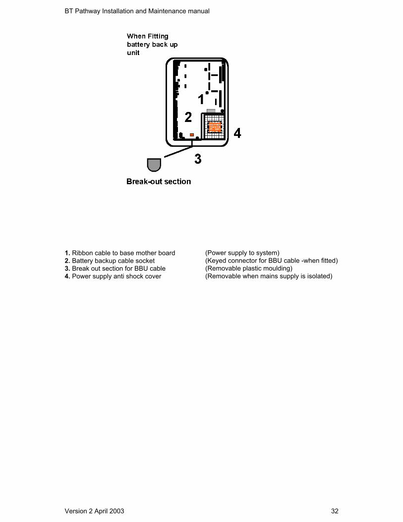
Installing the battery back-up
Caution - the diagram below shoes the Battery Back Up with the cover removed.
BT Pathway Installation and Maintenance manual
Version 2 April 2003 32
1. Ribbon cable to base mother board (Power supply to system)2. Battery backup cable socket (Keyed connector for BBU cable -when fitted)3. Break out section for BBU cable (Removable plastic moulding)4. Power supply anti shock cover (Removable when mains supply is isolated)

BT Pathway Installation and Maintenance manual
Version 2 April 2003 33
Mounting the Battery Backup unit
The Battery back up unit is mounted on the same bracket ad the main CCU. Please refer tothe section of this manual referring to the fixing of the CCU. The Battery Backup unit (BBU)contains a 7.2 Ah rechargeable Battery. This battery sits in a bracket within the BBU case.

BT Pathway Installation and Maintenance manual
Version 2 April 2003 34
Extension Port (22)
This port is designed to work up to a distance of 2 kilometres away from the main unit and isapproved for connection of 2-wire external extensions using PTO network cabling. Extension22 should be the only extension using this cable
Cable limitations:• 2-wire external extension = 2 kilometres maximum cabling distance or 3 dB at 1600 Hz.• The cable route should not be exposed to high voltage surges (e.g. Lightning) Note - These figures are assuming a cabling conductor size of 0.5mm copper diameter.
Central Bell It should be noted that the BT Pathway is provided with a connector for a Central Bell. This isa single pair on which ringing is supplied. The Central bell can be provided by running a cablepair from the Central Bell IDC see position 7 on the base motherboard to a master line jackunit. Bells/tone callers can then be connected to the line jack unit or hard-wired to LJUterminals 3 and 5.
Doorstrike The Doorstrike port provides a closed relay contact when in the operated condition. The relaycontact is designed for low voltage DC equipment and should not be used for any voltagesgreater than those specified within the technical specification. Note: All internal extensions terminated within the customer’s premises should connect intostandard line jack units. When extension 22 is using the long line facility (Max. 2 Km from theCCU) an earthed line surge protector should be fitted to the line.

BT Pathway Installation and Maintenance manual
Version 2 April 2003 35
General cabling and wiring information Do not exceed the following resistance limit when connecting extensions to the CCU (0.5 mmtinned copper conductor). 100 ohms or 300 metres for Systemphone extensions 100 ohms or 500 metres for standard 2-wire telephone extensions 336 ohms or 2 kilometres for 2-wire extension connected to extension position 22. Great care should be taken when selecting the cable routes to ensure that the cablingcomplies with current cabling requirements. The extension and ISDN line cables must be of twisted-pair construction using insulatedtinned copper wires of nominal 0.5mm cross-sectional area. It is important that this size andtype of wire is used as incorrect types could result in unreliable connections. The extension and ISDN line cables enter the CCU at the bottom left-hand side of the CCUwhen viewed from the front of the case. Pass the cables through the cable entry hole in theCCU case. The cables should then be passed through the cable retaining straps untiladjacent to the relevant connectors. There are punch-outs for the ISDN and V24 connectors. The cables should remain sheathed inside the CCU housing within reach of the connector.Guide the cables neatly into the channel space between the connector and the CCU caseside, ensuring that there is sufficient clearance between the cables and the CCU case lid.

BT Pathway Installation and Maintenance manual
Version 2 April 2003 36
MDF Wiring technique
Cable access via break-outpanel on bottom left of CCU housing
Install cablesalong the lefthand side ofthe base Motherboard (area in grey)and connect torequired terminals
BT Pathway Installation and Maintenance manual
Version 2 April 2003 37
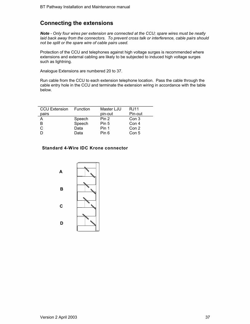
Connecting the extensions Note - Only four wires per extension are connected at the CCU; spare wires must be neatlylaid back away from the connectors. To prevent cross talk or interference, cable pairs shouldnot be split or the spare wire of cable pairs used. Protection of the CCU and telephones against high voltage surges is recommended whereextensions and external cabling are likely to be subjected to induced high voltage surgessuch as lightning. Analogue Extensions are numbered 20 to 37. Run cable from the CCU to each extension telephone location. Pass the cable through thecable entry hole in the CCU and terminate the extension wiring in accordance with the tablebelow. CCU Extension pairs
Function Master LJUpin-out
RJ11 Pin-out
A Speech Pin 2 Con 3 B Speech Pin 5 Con 4 C Data Pin 1 Con 2 D Data Pin 6 Con 5
Standard 4-Wire IDC Krone connector
A
B
C
D
BT Pathway Installation and Maintenance manual
Version 2 April 2003 38
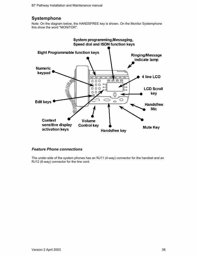
Systemphone Note: On the diagram below, the HANDSFREE key is shown. On the Monitor Systemphonethis show the word "MONITOR".
Feature Phone connections The under-side of the system phones has an RJ11 (4-way) connector for the handset and anRJ12 (6-way) connector for the line cord.
BT Pathway Installation and Maintenance manual
Version 2 April 2003 39
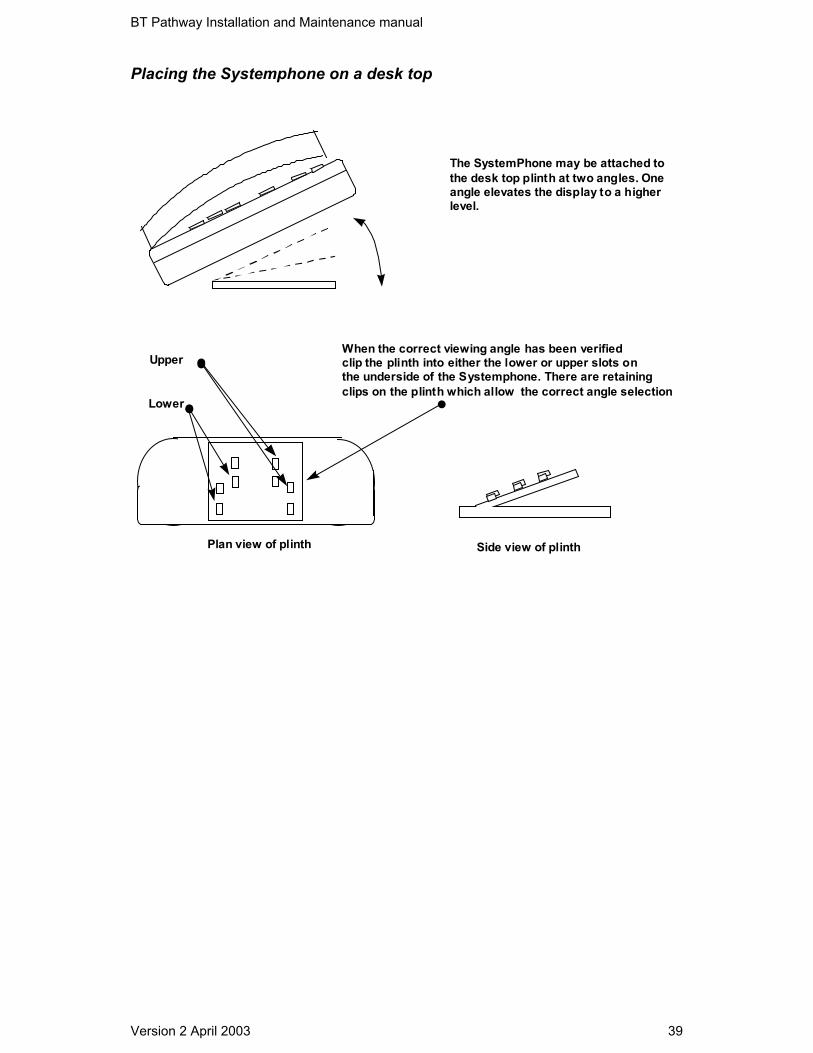
Placing the Systemphone on a desk top
The SystemPhone may be attached tothe desk top plinth at two angles. Oneangle elevates the display to a higherlevel.
When the correct viewing angle has been verifiedclip the plinth into either the lower or upper slots onthe underside of the Systemphone. There are retainingclips on the plinth which allow the correct angle selection
Plan view of plinth Side view of plinth
Upper
Lower

BT Pathway Installation and Maintenance manual
Version 2 April 2003 40
Wall mounting a Systemphone Locate, drill and plug the two screw locations as shown. The holes should be deep enough toaccept a 2.5cm screw. Screw in the two screws, leaving 3 or 4mm protruding. Remove theplinth from the base of the phone and locate the two keyhole slots on the base of the phoneover the two screws. Push the Systemphone down onto the protruding screw-heads the plinthis not used.
158mm
Locate the two mounting screws 158mm apart
The handset-retaining clip, located directly below the hook-switch, must be reversed so thatthe handset is secure when the phone is wall mounted.
Power fail
PSTN In the event of a total system power failure at least 50% of the equipped lines are switched toextensions. Lines 1 and 2 are power failed to extensions 24 and 25 the last two extensions onthe basic unit. Line 5 is power failed to extension 31 and Line 7 to extension 37, the lastextensions on each of the expansion boards.
NOTE: If lines are power failed to extension positions equipped with Systemphones the user mustreplace the Systemphone with a standard two-wire phone to answer or make calls.SYSTEMPHONES DO NOT OPERATE DURING POWER FAIL.
Line Position Power fail extension Line 1 Extn.24 Line 2 Extn 25 Line 5 Extn.31 Line 7 Extn 37 Each board with PSTN exchange line capability is equipped with a power fail circuit path ISDN In the event of a total system failure, the ISDN lines will NOT operate. ISDN devices can beconnected directly to the ISDN NTE or So bus and work independently of the system.

BT Pathway Installation and Maintenance manual
Version 2 April 2003 41
Connecting to the network
Analogue/PSTN lines The same IDC Krone connector type is used when terminating analogue lines as is used forterminating the extensions. In this case the first A-B pair is used to terminate one line and thesecond C-D pair is used to terminate the second line.
206 Line termination
L1 L2
PSTN
A
B
C
D
L1 A&B Pair
L2 C&D Pair
206 PSTN
PSTN ExpansionCard

BT Pathway Installation and Maintenance manual
Version 2 April 2003 42
412 Line termination
A B C DL1 L2PSTN
L1A&B Pair
L2C&D Pair
412 PSTN
PSTNCard
L4L3
A
B
C
D
L3A&B Pair
L4C&D Pair
PSTNCard
Extension expansioncard provides an IDCkrone connection forlines 5&6 on the firstexpansion card and lines7& 8 on the second card
L5 L6
Note: The system may be configured with eight analogue/PSTN lines. Where the line provision isnot supplied on the base motherboard, the incoming line termination is made on theextension expansion card. This IDC/Krone connector is located at position 7.

BT Pathway Installation and Maintenance manual
Version 2 April 2003 43
ISDN Lines
1 To6 ISDN
NTE
ISDN
Connect an ISDN cable fromthe Network terminator to the RJ45socket on the base mother board
ISDN ExpansionCard ISDN Upgrade module

BT Pathway Installation and Maintenance manual
Version 2 April 2003 44
S-Bus terminating socket
1 T0& Optional S0 fitted
1 To6 ISDN& So
NTE
ISDN
Connect an ISDN cable fromthe Network terminator to the To 1 RJ45socket on the base mother board
ISDN ExpansionCard as To
To 1 Connection RJ 45 8- Way connector
ISDN ExpansionCard as So
So Connection RJ 45 8- Way connector
CONNECT TO:Local Terminal AdapterLocal Data RouterLocal ISDN device
Installation completion & power up When the installation is complete please carry out the following procedures Wiring and module insertions • Ensure using suitable ESP, that all system module PCB’s are secured correctly and that
all column supports are fitted to their relevant positions• Visually verify all Krone IDC punch down terminations on positions fitted with
Systemphones and standard 2-wire POTS phones• Ensure there are no screws or metal objects loose within the CCU housing as this may
cause damage on power up• Refit the CCU cover
BT Pathway Installation and Maintenance manual
Version 2 April 2003 45
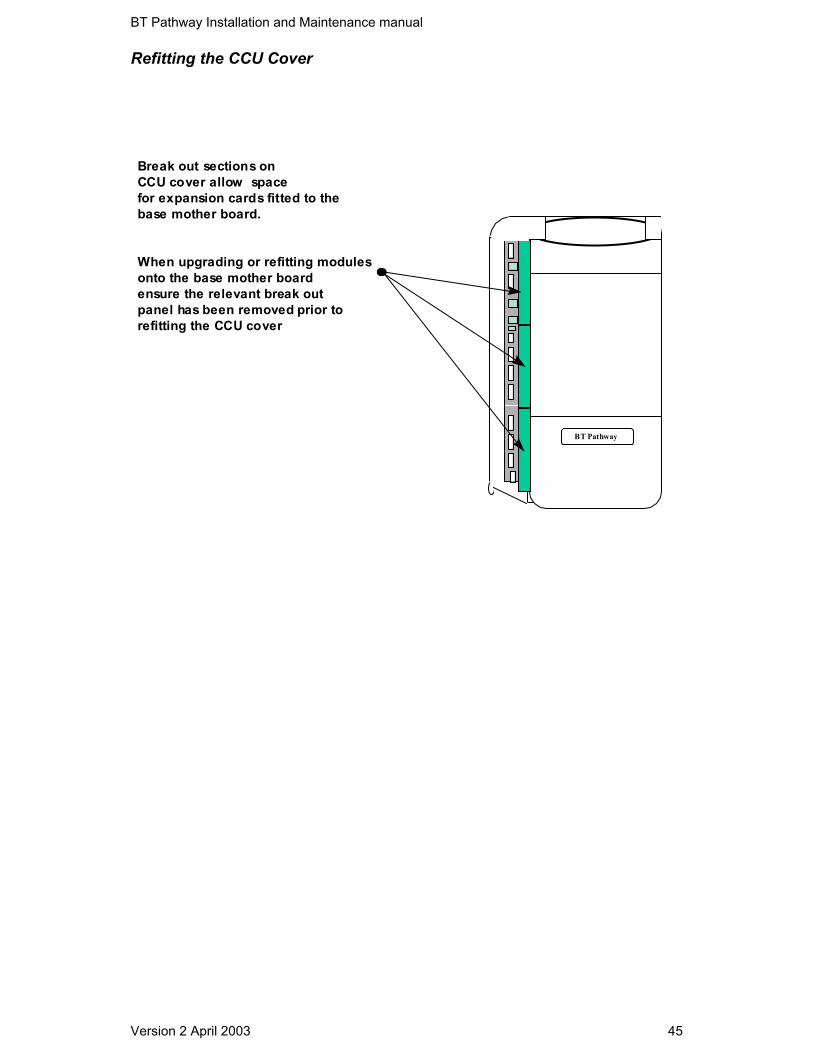
Refitting the CCU Cover
BT Pathway
Break out sections onCCU cover allow spacefor expansion cards fitted to thebase mother board.
When upgrading or refitting modulesonto the base mother boardensure the relevant break outpanel has been removed prior torefitting the CCU cover

BT Pathway Installation and Maintenance manual
Version 2 April 2003 46
Power up and test • Ensure the mains plug is fitted with a 3A cartridge fuse• Ensure there is a reliable mains earth in the supply socket outlet. This can be done using
a 13A socket earth loop impedance tester Switch on • Power up the system by inserting the mains plug• Wait 8-10 seconds for the system power up routine to be complete. During this period you
will hear several clicks from the working system as relays are energised• The Systemphones display the product name and software revision for about 1.5 seconds
Commissioning
1. Remove any anti-scratch protective film from Systemphone LCD2. Label-up all Systemphones and other telephones.3. Ensure that all Systemphones provide dialling tone, ringing and Handsfree/Monitor (loud
speaking) facilities. Check that the display is not showing corrupt information.4. Check that all other telephones are connected for dialling and ringing.5. Make essential changes from the default, for example:
PSTN System ISDN SystemEquipped Exchange lines Equipped Exchange linesDisconnect unused extensions Disconnect unused extensions
Enable features on the system for specific configurations
PSTN System ISDN SystemEnable DISA P to P or P to MPFax Detect Set BASE MSN & DDI index numbersvoicemail (Answer machine on I/C lines) CLI RoutingProgram door intercom voicemail (Answer machine on ISDN lines)Program PA position Program door intercomForward Recall - If system is piggy-backed Program PA positionMF/LD signalling PBX access - If system is piggy-backed
NoteAs the BT Pathway can support both ISDN and PSTN, it may be necessary to enablefeatures for ISDN and PSTN options on the same system.

BT Pathway Installation and Maintenance manual
Version 2 April 2003 47
Recommendations for Customer Training
When installing a BT Pathway at a customer site, you should:
Ensure that the customer has the Owner’s Manual and phone User Guides.
Show the customer how to do the following on their Systemphone:
• Use the function keys• Use the menus and associated keys• Program a key• Change the date and time• Put names onto the extensions• Use the Handsfree/Monitor key (explain how it works)• Transfer a call from an Systemphone to a standard phone (if fitted) and back• Use the Voice Module feature (if equipped)• Ensure the customer knows the basics of call handling on the switch
Troubleshooting All faults can normally be traced quite readily to a particular PCB. Some fault conditionsshould be checked to see if miss-programming the system has caused them to arise. • No incoming calls
Check that all phones programmed to ring are not programmed for DND (Do Not Disturb) • Extension outgoing locked
If you cannot get outgoing access on a 2-wire telephone, move a Systemphone to theextension. If it shows EXTN LOCK the extension has been locked and you will need thepadlock code to unlock it.
• No extension dial tone
Check that the extension has not been disconnected through programming • Not seizing a line for outgoing calls
Check if the line has been programmed for incoming calls only. Check if the line is equipped in programming.
• Feature phone shows “ Waiting for SYNC” - Extension not properly terminated atIDC/Krone connector
• Door intercom not operating Check Door intercom link is located correctly. Check the Door intercom programming.
• Phone reset Remember the simple phone reset code 157, which can be dialled from a phone.
• System reset
− Warm reset: To do a warm reset of the BT Pathway, enter the programmingmode and choose warm reset
− Cold reset: To do a cold reset of the BT Pathway, enter the programming mode
and choose cold reset
BT Pathway Installation and Maintenance manual
Version 2 April 2003 48
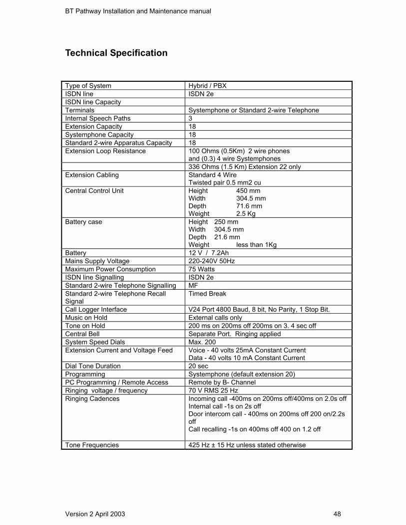
Technical Specification
Type of System Hybrid / PBXISDN line ISDN 2eISDN line CapacityTerminals Systemphone or Standard 2-wire TelephoneInternal Speech Paths 3Extension Capacity 18Systemphone Capacity 18Standard 2-wire Apparatus Capacity 18Extension Loop Resistance 100 Ohms (0.5Km) 2 wire phones
and (0.3) 4 wire Systemphones336 Ohms (1.5 Km) Extension 22 only
Extension Cabling Standard 4 WireTwisted pair 0.5 mm2 cu
Central Control Unit Height 450 mmWidth 304.5 mmDepth 71.6 mmWeight 2.5 Kg
Battery case Height 250 mmWidth 304.5 mmDepth 21.6 mmWeight less than 1Kg
Battery 12 V / 7.2AhMains Supply Voltage 220-240V 50HzMaximum Power Consumption 75 WattsISDN line Signalling ISDN 2eStandard 2-wire Telephone Signalling MFStandard 2-wire Telephone RecallSignal
Timed Break
Call Logger Interface V24 Port 4800 Baud, 8 bit, No Parity, 1 Stop Bit.Music on Hold External calls onlyTone on Hold 200 ms on 200ms off 200ms on 3. 4 sec offCentral Bell Separate Port. Ringing appliedSystem Speed Dials Max. 200Extension Current and Voltage Feed Voice - 40 volts 25mA Constant Current
Data - 40 volts 10 mA Constant CurrentDial Tone Duration 20 secProgramming Systemphone (default extension 20)PC Programming / Remote Access Remote by B- ChannelRinging voltage / frequency 70 V RMS 25 HzRinging Cadences Incoming call -400ms on 200ms off/400ms on 2.0s off
Internal call -1s on 2s offDoor intercom call - 400ms on 200ms off 200 on/2.2soffCall recalling -1s on 400ms off 400 on 1.2 off
Tone Frequencies 425 Hz ± 15 Hz unless stated otherwise

BT Pathway Installation and Maintenance manual
Version 2 April 2003 49
Tone Cadences Dial Tone - Continuous tone of 440Hz ±5% and350Hz±5% combinedSpecial Dial tone - 800ms on 800ms off of 440Hz ±5%and350Hz ±5% combinedRingback Tone - 400ms on 200ms off 400ms on 2secoffBusy Tone - 400ms on 400ms offCongestion Tone - 100ms on 100ms offHold Tone - 200ms on 200ms off 200ms on 3.4 secoffConference tone - One burst of 400ms.NU tone - Continuous toneCall waiting tone - 100ms on 4.9 s off
Environmental Requirements Normal working temperature 0°C to 45°CWorking humidity (non condensing) 10% to 80%Storage temperature -20°C to +70°CStorage humidity 10% to 90%
Doorstrike Relay Contact Max Rating 24 Volts DC 2 Amps
Safety and Protection EN60950EN41003 and EN300-047
system software EPROM Flash 4 Mb; access-time < 120 ns
Music on Hold or Courtesy serviceEPROM
1 or 2 Mb:
BT Pathway Installation and Maintenance manual
Version 2 April 2003 50
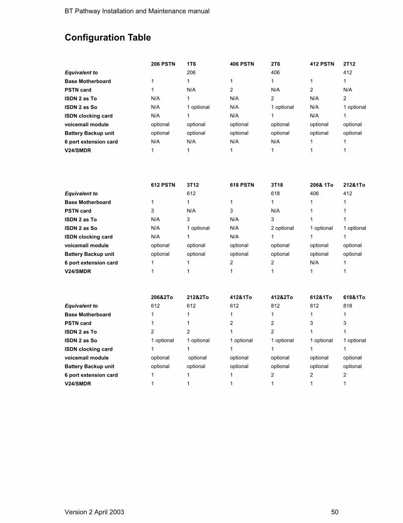
Configuration Table
206 PSTN 1T6 406 PSTN 2T6 412 PSTN 2T12Equivalent to 206 406 412Base Motherboard 1 1 1 1 1 1PSTN card 1 N/A 2 N/A 2 N/AISDN 2 as To N/A 1 N/A 2 N/A 2ISDN 2 as So N/A 1 optional N/A 1 optional N/A 1 optionalISDN clocking card N/A 1 N/A 1 N/A 1voicemail module optional optional optional optional optional optionalBattery Backup unit optional optional optional optional optional optional6 port extension card N/A N/A N/A N/A 1 1V24/SMDR 1 1 1 1 1 1
612 PSTN 3T12 618 PSTN 3T18 206& 1To 212&1ToEquivalent to 612 618 406 412Base Motherboard 1 1 1 1 1 1PSTN card 3 N/A 3 N/A 1 1ISDN 2 as To N/A 3 N/A 3 1 1ISDN 2 as So N/A 1 optional N/A 2 optional 1 optional 1 optionalISDN clocking card N/A 1 N/A 1 1 1voicemail module optional optional optional optional optional optionalBattery Backup unit optional optional optional optional optional optional6 port extension card 1 1 2 2 N/A 1V24/SMDR 1 1 1 1 1 1
206&2To 212&2To 412&1To 412&2To 612&1To 618&1ToEquivalent to 612 612 612 812 812 818Base Motherboard 1 1 1 1 1 1PSTN card 1 1 2 2 3 3ISDN 2 as To 2 2 1 2 1 1ISDN 2 as So 1 optional 1 optional 1 optional 1 optional 1 optional 1 optionalISDN clocking card 1 1 1 1 1 1voicemail module optional optional optional optional optional optionalBattery Backup unit optional optional optional optional optional optional6 port extension card 1 1 1 2 2 2V24/SMDR 1 1 1 1 1 1
BT Pathway Installation and Maintenance manual
Version 2 April 2003 51
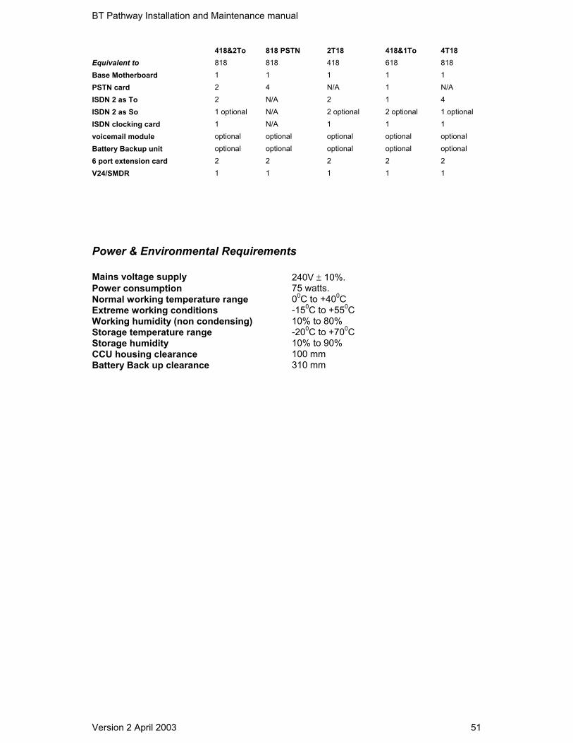
418&2To 818 PSTN 2T18 418&1To 4T18Equivalent to 818 818 418 618 818Base Motherboard 1 1 1 1 1PSTN card 2 4 N/A 1 N/AISDN 2 as To 2 N/A 2 1 4ISDN 2 as So 1 optional N/A 2 optional 2 optional 1 optionalISDN clocking card 1 N/A 1 1 1voicemail module optional optional optional optional optionalBattery Backup unit optional optional optional optional optional6 port extension card 2 2 2 2 2V24/SMDR 1 1 1 1 1
Power & Environmental Requirements
Mains voltage supply 240V ± 10%.Power consumption 75 watts.Normal working temperature range 00C to +400CExtreme working conditions -150C to +550CWorking humidity (non condensing) 10% to 80%Storage temperature range -200C to +700CStorage humidity 10% to 90%CCU housing clearance 100 mmBattery Back up clearance 310 mm