Initial Calibration and Stability Results from the LiCAS RTRS FSI System John Dale for the LiCAS...
19
Initial Calibration and Stability Results from the LiCAS RTRS FSI System John Dale for the LiCAS Collaboration IWAA February 2008
-
date post
20-Dec-2015 -
Category
Documents
-
view
218 -
download
3
Transcript of Initial Calibration and Stability Results from the LiCAS RTRS FSI System John Dale for the LiCAS...

Initial Calibration and Stability Results from the LiCAS RTRS
FSI System
John Dale for the LiCAS Collaboration
IWAA February 2008
2
Introduction
• Frequency Scanning Interferometry (FSI)• Reference Interferometers
– Design– Initial Length Calibration– Initial Thermal Calibration
• LiCAS Train FSI Measurement Sub-Systems– Initial Stability of the External FSI Sub-System– Initial Stability of the Internal FSI Sub-System
3
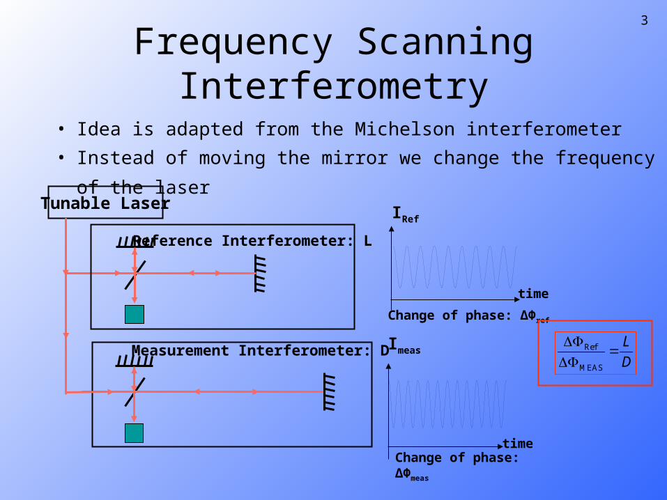
Frequency Scanning Interferometry
Tunable Laser
Reference Interferometer: L
Measurement Interferometer: D
Change of phase: ΔΦmeas
Change of phase: ΔΦref
time
IRef
time
Imeas Ref
MEAS
L
D
• Idea is adapted from the Michelson interferometer
• Instead of moving the mirror we change the frequency of the laser
4
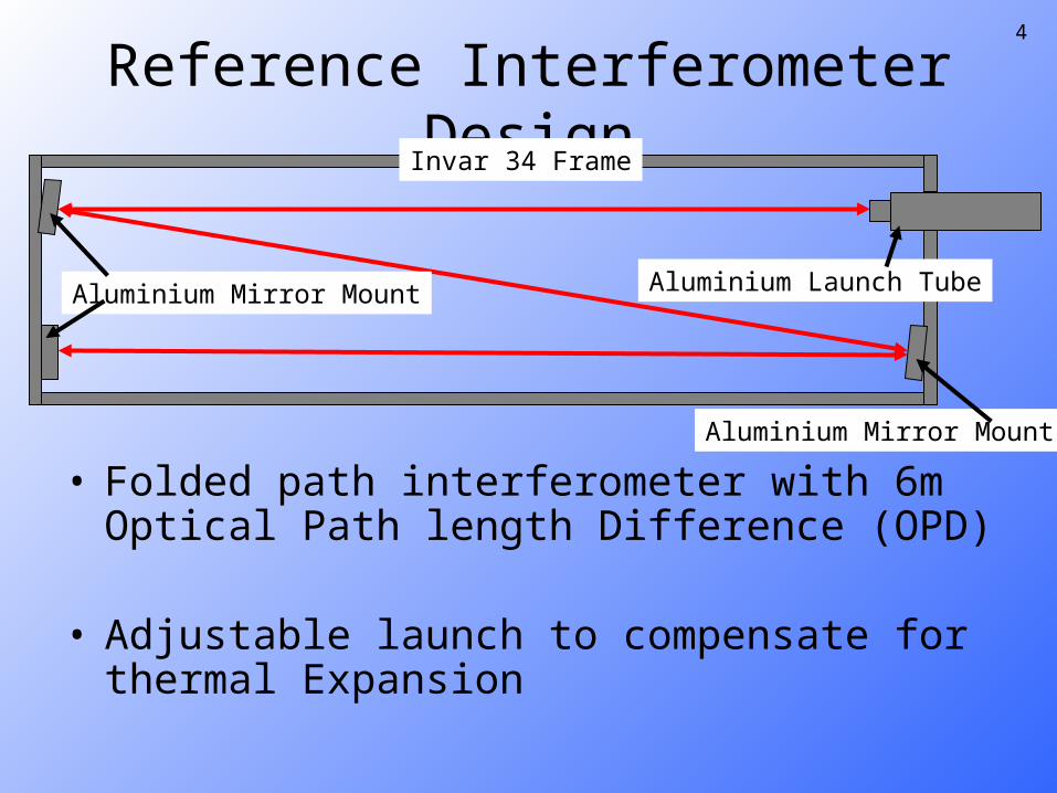
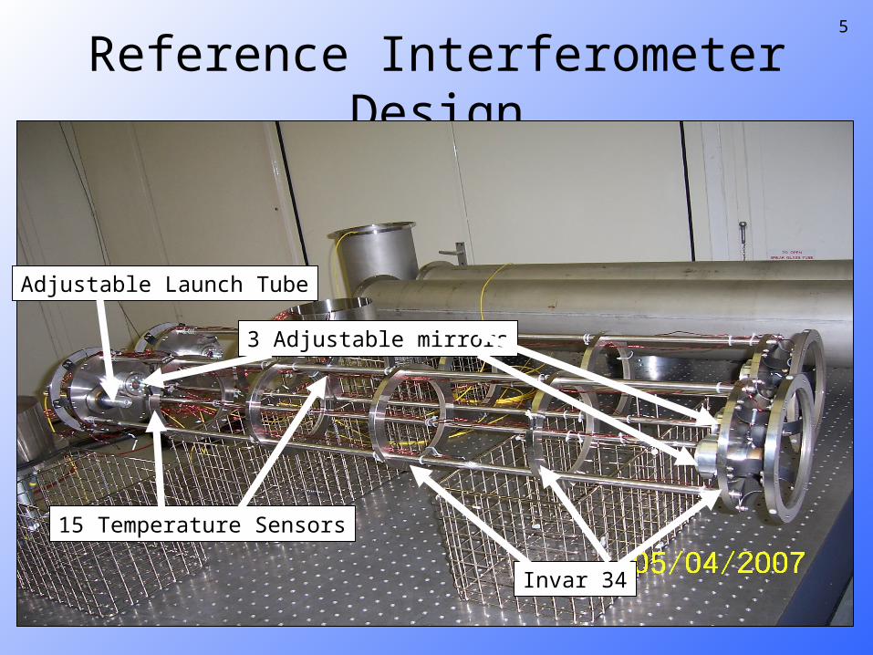
Reference Interferometer Design
• Folded path interferometer with 6m Optical Path length Difference (OPD)
• Adjustable launch to compensate for thermal Expansion
Aluminium Mirror Mount
Aluminium Launch TubeAluminium Mirror Mount
Invar 34 Frame
5
Reference Interferometer Design
Invar 34
15 Temperature Sensors
3 Adjustable mirrors
Adjustable Launch Tube

6
Length Calibration MethodReference Interferometer: LrefTunable Laser
Motion Stage Laser Tracker
Retro Reflectors
LStageInitial ΔL
• FSI System Measures Length Ratio at each Position
• Laser Tracker Measure Length Change to each Position
7
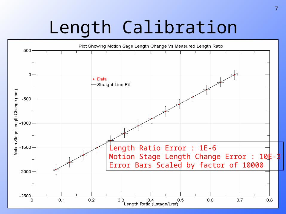
Length Calibration
stageInitialratio
ref
L LL
L
ref ratio stageInitialL L L L
• Plot ΔL vs Lratio
• Gradient of the line is Lref
Length Ratio Error : 1E-6Motion Stage Length Change Error : 10E-3Error Bars Scaled by factor of 10000

8
Expected 10E-3
Expected 1E-6
Length Calibration
RMS 3.9E-7
RMS 3.1E-3

9
Length Calibration Fit Results
• Fit give reference length of– 3.2521901 +/- 3E-6 m
• To improve value : – Take smaller steps– Use Laser tracker in optimum position and
more accurate mode– Cover optical path to reduce air turbulence
10
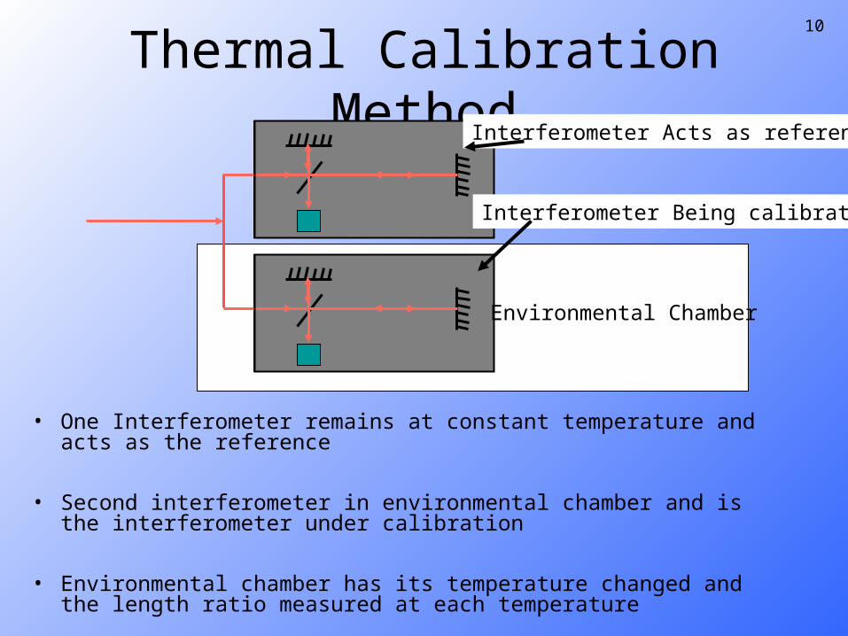
Thermal Calibration Method
Environmental Chamber
Interferometer Acts as reference
Interferometer Being calibrated
• One Interferometer remains at constant temperature and acts as the reference
• Second interferometer in environmental chamber and is the interferometer under calibration
• Environmental chamber has its temperature changed and the length ratio measured at each temperature
11
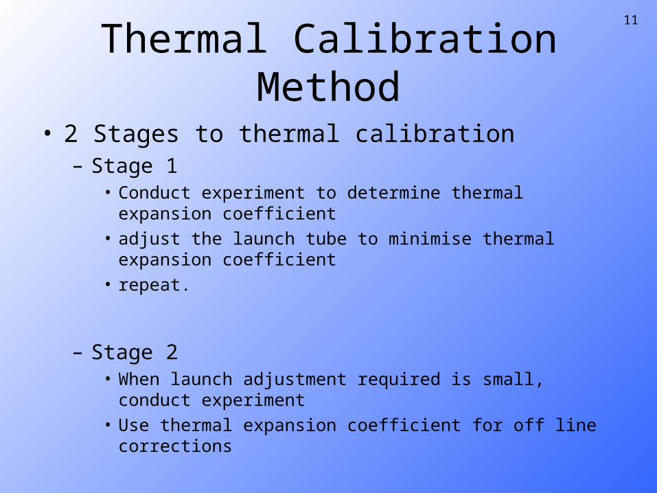
Thermal Calibration Method
• 2 Stages to thermal calibration– Stage 1
• Conduct experiment to determine thermal expansion coefficient
• adjust the launch tube to minimise thermal expansion coefficient
• repeat.
– Stage 2• When launch adjustment required is small, conduct
experiment • Use thermal expansion coefficient for off line corrections
12
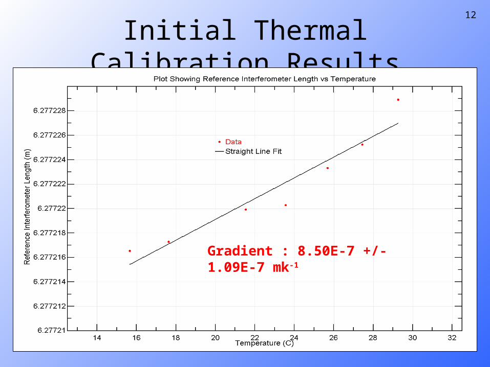
Initial Thermal Calibration Results
Gradient : 8.50E-7 +/- 1.09E-7 mk-1

13
Retro Reflector
External FSI Sub-System
• System responsible for measuring wall markers• Unit has 6 FSI Lines• Note: These are bare fibres with no collimators
or beam splitters• All 6 fibres monitor the same retro reflector
LiCAS RTRS Unit
FSI Line
Wall
Retro Reflector
FSI Lines
14
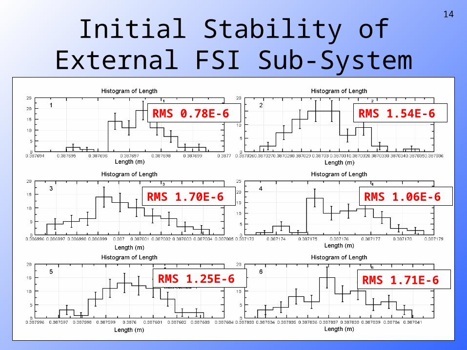
Initial Stability of External FSI Sub-System
RMS 1.71E-6
RMS 1.06E-6
RMS 1.54E-6 RMS 0.78E-6
RMS 1.70E-6
RMS 1.25E-6

15
External Marker Reconstruction Using External FSI Lines
RMS 1.26E-6
RMS 0.57E-6
RMS 3.12E-6
16
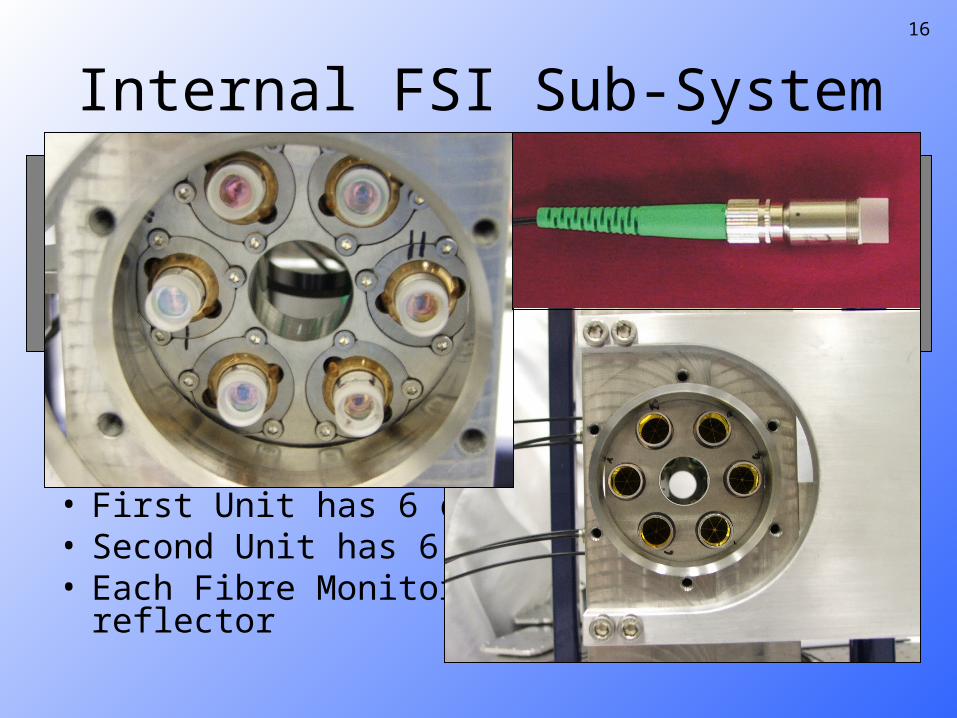
Internal FSI Sub-System
• Used to determine the distance from one unit to the next
• First Unit has 6 collimated fibres• Second Unit has 6 retro Reflectors• Each Fibre Monitors a different retro reflector
LiCAS RTRS UnitLiCAS RTRS Unit
Collimated fibreRetro Reflector
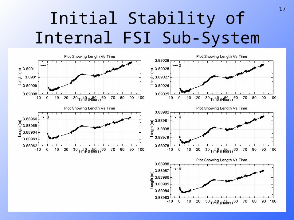
17
Initial Stability of Internal FSI Sub-System
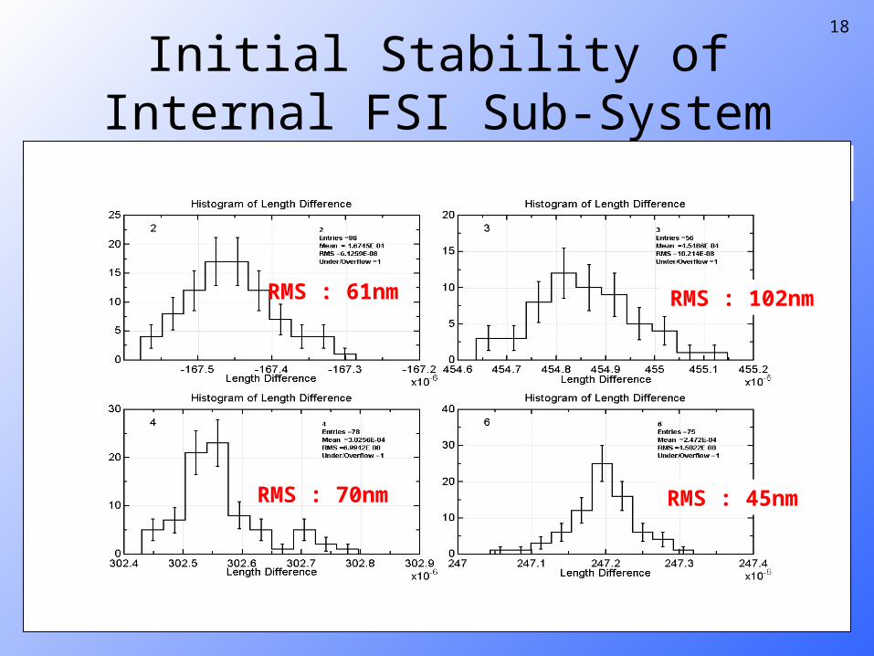
18
Initial Stability of Internal FSI Sub-System
1
2 3
4
6 5
0.8 E-6
0.6 E-6
0.25 E-6
0.3 E-6
Units Have Rotated By : 16 μradian
RMS : 61nm
RMS : 45nmRMS : 70nm
RMS : 102nm

19
Summary
• Reference Interferometers are under calibration
• External FSI System giving precision of 1-1.5 µm
• We have the ability to reconstruct wall marker positions to a precision of order 1.5µm
• Internal FSI System giving precision of 45 -100 nm