Initial Access in mm-wave 5G Mobile...
55
Initial Access in mm-wave 5G Mobile Communications Master’s thesis in Master Programme of Communication Engineering Hao Guo Department of Electrical Engineering CHALMERS UNIVERSITY OF TECHNOLOGY Gothenburg, Sweden 2017
Transcript of Initial Access in mm-wave 5G Mobile...

Initial Access in mm-wave5G Mobile CommunicationsMaster’s thesis in Master Programme of Communication Engineering
Hao Guo
Department of Electrical EngineeringCHALMERS UNIVERSITY OF TECHNOLOGYGothenburg, Sweden 2017


Master’s thesis: EX013/2017
Initial Access in mm-wave5G Mobile Communications
Hao Guo
Department of Electrical EngineeringCommunication and Antenna systems Group
Master Programme of Communication EngineeringChalmers University of Technology
Gothenburg, Sweden 2017

Initial Access in mm-wave 5G Mobile CommunicationsHao Guo
© Hao Guo, 2017.
Supervisor: Behrooz MakkiExaminer: Tommy Svensson
Master’s Thesis: EX013/2017Department of Electrical EngineeringCommunication and Antenna systems GroupMaster Programme of Communication EngineeringChalmers University of TechnologySE-412 96 GothenburgTelephone +46 31 772 1000
Typeset in LATEXPrinted by Chalmers ReproserviceGothenburg, Sweden 2017
iv

Initial Access in mm-wave 5G Mobile Communications
AbstractInitial access beamforming is identified as a key challenge for the upcoming 5Gmobile communication systems operating at high carrier frequencies, and severaltechniques are currently being proposed. In this thesis, we first give a brief in-troduction to 5G millimeter wave systems, initial access procedures as well as thecodebook-based beamforming. Then, we study the performance of initial accessbeamforming schemes in the cases with large-but-finite number of transmit antennasand single-antenna users. Particularly, we develop an efficient beamforming schemeusing genetic algorithms with the algorithm running delay taken into account. Asshown, our proposed algorithm is generic in the sense that it can be effectively ap-plied with different channel models, metrics and beamforming methods. Also, ourresults indicate that the proposed scheme can reach (almost) the same end-to-endthroughput as the exhaustive search-based optimal approach with considerably lessimplementation complexity.
As the second part of the work, we extend our proposed genetic algorithm-basedbeamforming scheme to include beamforming at both the transmitter and the re-ceivers. Also, we compare the system performance with different state-of-the-artbeamforming approaches in the millimeter wave multi-user multiple-input- multiple-output networks. Taking the millimeter wave communication characteristics andvarious metrics into account, we investigate the effect of different parameters suchas the number of transmit antennas/users/per-user receive antennas, beamformingresolutions as well as hardware impairments on the system performance employingdifferent beamforming algorithms. As shown, our proposed genetic algorithm-basedapproach performs well in delay-constrained networks with multi-antenna users.Compared to the considered state-of-the-art schemes, our method reaches the high-est service outage-constrained end-to-end throughput with considerably less imple-mentation complexity.
Keywords: Initial access beamforming; Millimeter wave communications; Multi-usermultiple-input-multiple-output networks; Throughput
v


AcknowledgementsI would like to take this opportunity to thank Prof. Tommy Svensson and Dr.Behrooz Makki for giving me this opportunity to join the Communication group asa one-year master thesis student. It has been very enjoyable learning and workinghere.
I would like to express my thanks to Prof. Tommy Svensson for being a great advisorsince we first met in Nankai University, Tianjin. Your enthusiasm and professionalpresentation gave me a good first impression of Chalmers and Sweden. During mymaster study, you helped me to get used to the new environment and gave me usefuladvices on choosing courses. In the second year, you offered me a good chance tostart my research work with a one-year master thesis training. I am always im-pressed by all your awesome research ideas and your advices on presentations andwritings help me a lot.
My deep gratitude goes to my supervisor Dr. Behrooz Makki. We started our at-any-moment meetings even before my thesis topic were settled, and it has been along and enjoyable journey since then. You have helped me through so many toughmoments with full supports and great patience. Nothing would have been possiblewithout you.
I am thankful for all the valuable suggestions and help from professors and PhDstudents in the S2 department. Especially thanks to Chao Fang, you have helpedme so much with thesis writing and attending the academic meeting. I would alsolike to thank JinLin Liu as well. You gave me great advices both professionallyand personally. My great thanks to Pavel Gueorguiev for sharing your impressiveknowledge on programming skills. My spoken English improved a lot with you. Ialso thank people in the thesis room for being nice and friendly.
Finally, I sincerely appreciate my parents for their unconditional love.
The research leading to these results received funding from the European Com-mission H2020 programme under grant agreement n◦671650 (5G PPP mmMAGICproject), and from the Swedish Governmental Agency for Innovation Systems (VIN-NOVA) within the VINN Excellence Center Chase, which are gratefully acknowl-edged.
Hao Guo, Gothenburg, April 2017
vii


List of acronyms
ADC Analog-to-Digital ConverterBF Beamformingbpcu bit-per-channel-useBS Base StationCSI Channel State InformationDFT Discrete Fourier TransformGA Genetic AlgorithmIA Initial AccessIID Independent and Identically DistributedLOS Line-of-SightLTE Long Term Evolutionmm-wave Millimeter WaveMU-MIMO Multi-User Multiple-Input-Multiple-OutputNLOS Non-Line-of-SightPA Power AmplifierPSS Primary Synchronization SignalRA Random AccessSINR Signal-to-Interference-plus-Noise RatioUE User EquipmentWLANs Wireless Local Area Networks5G 5th Generation Wireless Systems
ix

Contents
I Introductory Chapters
1 Background 11.1 5G Millimeter Wave (mm-wave) Networks . . . . . . . . . . . . . . . 1
1.1.1 Starting Point: New Frequency Bands, More Users . . . . . . 21.1.2 Key Requirements: High Data Rate and Low Latency . . . . . 21.1.3 One Solution: Effective Initial Access Beamforming . . . . . . 3
1.2 Initial Access Procedure . . . . . . . . . . . . . . . . . . . . . . . . . 51.3 Codebook-based Beamforming . . . . . . . . . . . . . . . . . . . . . . 61.4 Analog/Digital/Hybrid Beamforming . . . . . . . . . . . . . . . . . . 7
2 Related Works 9
3 System Model 113.1 Channel Model . . . . . . . . . . . . . . . . . . . . . . . . . . . . . . 113.2 Pre-defined Codebook . . . . . . . . . . . . . . . . . . . . . . . . . . 123.3 Performance Metrics . . . . . . . . . . . . . . . . . . . . . . . . . . . 123.4 Power Amplifier Efficiency . . . . . . . . . . . . . . . . . . . . . . . . 13
4 Genetic Algorithm (GA)-based Beamforming Approach 154.1 Beamforming Approach in Single-Antenna User Networks . . . . . . . 154.2 Extension of the GA-based Scheme and Considered State-of-the-art
Methods . . . . . . . . . . . . . . . . . . . . . . . . . . . . . . . . . . 15
5 Simulation Results 175.1 On the Advantages of the GA-based Approach . . . . . . . . . . . . . 17
5.1.1 A Convergence Example . . . . . . . . . . . . . . . . . . . . . 185.1.2 Performance Analysis for Different Parameters . . . . . . . . . 19
5.1.2.1 On the Effect of the Channel Condition . . . . . . . 195.1.2.2 On the Effect of the Codebook Size . . . . . . . . . . 195.1.2.3 On th Effect of Service Outage Constraint . . . . . . 20
5.1.3 On the Effect of the Imperfect Power Amplifier . . . . . . . . 215.2 Different State-of-the-art Approaches . . . . . . . . . . . . . . . . . . 21
5.2.1 Comparison of the Service Outage-Constrained End-to-endThroughput . . . . . . . . . . . . . . . . . . . . . . . . . . . . 21
5.2.2 Comparison of the Implementation Complexity . . . . . . . . 22
xi

Contents
6 Summary of Included Papers 256.1 A Genetic Algorithm-based Beamforming Approach for Delay-constrained
Networks . . . . . . . . . . . . . . . . . . . . . . . . . . . . . . . . . . 256.2 A Comparison of IA Beamforming Algorithms for Millimeter Wave
Networks . . . . . . . . . . . . . . . . . . . . . . . . . . . . . . . . . . 26
7 Future Work 27
Bibliography 29
II Included Papers
xii

Part I
Introductory Chapters


1Background
The 5th generation wireless systems (5G) is referred to as the proposed next telecom-munications standards that should be rolled out by 2020 to meet business and con-sumer demands [1]. As one of the key features, 5G will support operations in thenew range of 6-100 GHz, also known as the millimeter wave (mm-wave) spectrum.
Due to peak power limitation and severe path loss, mm-wave systems generallyrequire high base station density to reach acceptable coverage. Extremely densemm-wave networks will have the interference management issue. As one of the keytechniques in wireless communications, beamforming (BF) can be a good techniqueto mitigate the poor coverage range and improve the system throughput. Fortu-nately, the physical size of antennas at mm-wave frequencies is normally small,which gives a strong hardware support for employing large-scale BF. However, weneed to have BF also in the control and pilot channels, implying that it is much moredifficult to obtain the channel state information (CSI) since we have no sector-widebroadcast channel in the mm-wave system. One of the solutions for these problemsis the codebook-based BF during initial access (IA) procedure which can improvethe system performance without the requirements of the perfect CSI.
In this perspective, this thesis studies, designs and compares different schemes forIA BF in mm-wave communications. The main contents of this MSc thesis are:
* Introduce the background knowledge of 5G, IA procedures as well as thecodebook-based BF,
* Perform a literature review on related research works,* Propose a genetic algorithm (GA)-based BF approach for mm-wave multi-usermultiple-input-multiple-output (MU-MIMO) networks,
* Evaluate the system performance with different parameter settings,* Compare an extended GA-based scheme using multi-antennas also on theuser side with the state-of-the-art approaches in terms of both service outage-constrained end-to-end throughput and implementation complexity.
1.1 5G Millimeter Wave (mm-wave) Networks
In this section, we start with the recent developments of 5G, explaining two keyrequirements and pointing out one practical solution. These background knowledgecould give us a clear picture of the exact purposes of our work.
1
1. Background
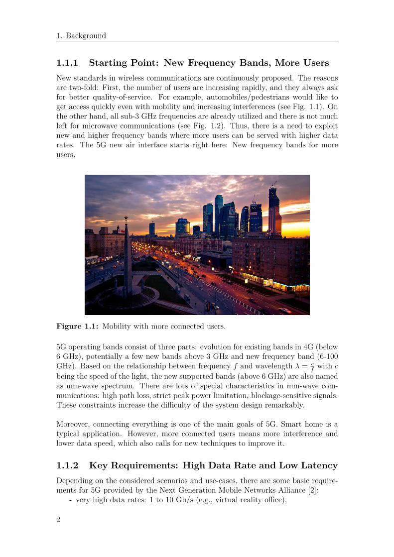
1.1.1 Starting Point: New Frequency Bands, More UsersNew standards in wireless communications are continuously proposed. The reasonsare two-fold: First, the number of users are increasing rapidly, and they always askfor better quality-of-service. For example, automobiles/pedestrians would like toget access quickly even with mobility and increasing interferences (see Fig. 1.1). Onthe other hand, all sub-3 GHz frequencies are already utilized and there is not muchleft for microwave communications (see Fig. 1.2). Thus, there is a need to exploitnew and higher frequency bands where more users can be served with higher datarates. The 5G new air interface starts right here: New frequency bands for moreusers.
Figure 1.1: Mobility with more connected users.
5G operating bands consist of three parts: evolution for existing bands in 4G (below6 GHz), potentially a few new bands above 3 GHz and new frequency band (6-100GHz). Based on the relationship between frequency f and wavelength λ = c
fwith c
being the speed of the light, the new supported bands (above 6 GHz) are also namedas mm-wave spectrum. There are lots of special characteristics in mm-wave com-munications: high path loss, strict peak power limitation, blockage-sensitive signals.These constraints increase the difficulty of the system design remarkably.
Moreover, connecting everything is one of the main goals of 5G. Smart home is atypical application. However, more connected users means more interference andlower data speed, which also calls for new techniques to improve it.
1.1.2 Key Requirements: High Data Rate and Low LatencyDepending on the considered scenarios and use-cases, there are some basic require-ments for 5G provided by the Next Generation Mobile Networks Alliance [2]:
- very high data rates: 1 to 10 Gb/s (e.g., virtual reality office),
2

1. Background
Figure 1.2: U.S. Frequency Allocation Chart as of January 2016. (Available at:https://www.ntia.doc.gov/page/2011/united-states-frequency-allocation-chart)
- very low end-to-end latency: less than 5 ms (e.g., traffic safety),- large number of connected devices: up to 300,000 devices per access point(e.g., massive deployment of sensors),
- high reliability: 99.999% (e.g., tele-protection in smart grid networks),
in which the most important requirements are high data rates and low latency. Thismeans that we need to find low-complexity techniques which can increase the datarate and reduce the latency remarkably.
1.1.3 One Solution: Effective Initial Access BeamformingBF, also known as spatial filtering, is an important technique in wireless commu-nications. It aims at forming high directional transmit/receive beam patterns byantenna arrays and phase shifters [3]. Conventional BF is performed by precoding/-combing with CSI after stable links have been established. However, it is difficult toacquire CSI at mm-wave bands. Moreover, due to the high path loss, the coveragerange for mm-wave frequencies is still small even with the extension by BF. To mit-igate these constraints in the mm-wave spectrum, employing the codebook-basedBF with large antenna arrays before links have been established, i.e., the IA BF,would be one of the feasible solutions to satisfy the throughput requirement withimperfect CSI (see Fig. 1.3).
Moreover, the word access means that there is a threshold to decide whether or notthe user equipments (UEs) have been connected to the base stations (BSs). Onereasonable situation is that the users’ received signal-to-interference-plus-noise ra-tio (SINR) should be above predefined thresholds, as it includes both the receivedpower limitation and the interferences from other users.
3

1. Background
Antenna array at the BS
UE
UEUE
UE
UE
Figure 1.3: A sketch map for a multi-user system employing BF to realise highdirectional communications.
As mentioned before, low end-to-end latency is one of the key requirements for mm-wave mobile communications. For this reason, the time cost for the BF schemeshould be carefully considered during the design procedure. To present the trade-offthat more BF time can get better beam resolution but reduces data transmissiontime (see Fig. 1.4), in our system, we take the cost of running the algorithm intoaccount so that the maximum throughput is obtained by finding a suboptimal BFmatrix while the rest of the time slot is used for data transmissions. A convergenceexample in section 5.1.1 also describes this trade-off in detail.
Beamforming
Data TransmissionTotal Package
transmission time
Figure 1.4: Time structure for the delay-constrained system.
4

1. Background
1.2 Initial Access ProcedureBasically, the steps for the mm-wave IA is similar to those in Long Term Evolution(LTE), which are proposed in some standard texts such as [4]. However, the proce-dures need to be modified for mm-wave because we want to employ BF before theUE and the BS detect each other. These steps are, namely, Cell Search, RandomAccess, and Scheduled Communications, which are also presented in Fig. 1.5. Notethat the most challenging part of mm-wave IA is to decide the beam directions ofthe BS and the UE and, for this reason, we mainly focus on the first and the thirdstep.
BS UE
Step 1 Cell Search
Step 3 Scheduled Communication
Step 2 Random Access
Figure 1.5: Steps for IA procedure.
1) Cell Search: The BS periodically broadcasts the synchronization signal withdifferent beam direction to the UE, which is similar to the Primary Synchro-nization Signal (PSS) in LTE. The only difference is the synchronization signalis also used to perform BF. At the receive side, the UE will decide their beamdirection if the synchronization signal is detected. There would be some cer-tain thresholds for the UE to determine whether or not it has been connectedto the link. After trying a certain number of synchronization signals, the UEcan make a decision of the optimal beam direction.
2) Random Access (RA): In this step, both the BS and the UE know thepreliminary directions through which they should steer their beams. They willexchange the random access messages in order to establish the link, including– RA preamble transmission: The UE randomly selects a small number of
waveforms (named as preamble) and transmits to the BS.– RA response: The BS sends a response message with an initial timing
5

1. Background
and power correction as well as some access control identifier to preciselyidentify the UE.
– Connection request: The UE responses back the connection request mes-sage with some authentication and identification information.
3) Scheduled Communications: Beam training/refinement can be applied inthis part to further optimize beam searching results in the previous stepsby steering beams, where the user mobility can also be handled. After thisstep, messages can be transmitted/received with full BF gain using scheduledchannels.
1.3 Codebook-based Beamforming
A codebook is a matrix, where each column represents a weight vector of antennasand can form a certain beam pattern (See Fig. 1.6). As we mentioned before,due to the large feedback/estimation overhead and high path loss, it is difficult toacquire CSI at mm-wave, which means conventional CSI-based precoding/combingschemes may be infeasible. In this case, the pre-defined codebook can be used togenerate directional transmitted/received beams in Step 1) and Step 3). Our goal isto propose an efficient IA BF algorithm. From the codebook perspective, this meanswe want to design a low-delay algorithm to find the (sub)optimal sets of codebookvectors. We use the GA principle, running iterations continuously based on previous-round solutions, and finally reaching an appropriate (sub)optimal solution. Detailsof the beam searching algorithm can be seen in Chapter 4.
Figure 1.6: Codebook-based BF.
6
1. Background
1.4 Analog/Digital/Hybrid BeamformingThis section can be part of the thesis scope. It is important to know the BFtype of our system, in terms of analog/digital/hybrid BF, and more specifically,amplitude/phase-based BF.
The definition of the BF type is based on the signal type that the BF is appliedto [5]. For example, analog BF means amplitude/phase variation is applied to theanalog signal before the analog-to-digital converter (ADC) while digital BF meansamplitude/phase variation is applied to the digital signal resulted from the ADC.
For the analog BF, the receiver can “look” in only one or a small number of direc-tions at a time, while in the digital BF the receiver can look in all directions at once.However, digital BF requires more ADCs compared to analog BF. This increases thepower consumption to unacceptable levels, especially at the UE side. One possiblesolution can be to apply low-complexity digital BF [6] which means using few bitsADCs to get a good trade-off. Indeed, the advantage of analog and digital BF canbe combined by employing hybrid BF, in which the BF efficiency is favorable withacceptable implementation complexity.
In this thesis work, we consider the analog BF with phase variation only. In thiscase, there are a limited number of columns in the codebook and it’s possible tosearch for the optimal BF within a short period. Our proposed algorithm can beapplied to digital/hybrid BF, and it will be part of our future work.
7

1. Background
8

2Related Works
In this chapter, we want to collect the recent research works on the IA BF in threeaspects: 1) IA in 5G systems, 2) codebook-based BF, 3) different beam searchingalgorithms.
Different standards have developed mm-wave BF technique such as IEEE 802.15.3c(TG3c) [7], IEEE 802.11ad (TGad)[8] and ECMA-387[9].
• Cell discovery: In [10], the technical details of BF at mm-wave frequency aredescribed and a hierarchical search strategy is designed. Then, [11] proposesa directional downlink cell search method in a mm-wave cell. The results of[11] are extended in [6] where it looks at the whole IA procedure with differentdesign options and evaluates the overall delay to determine the control planelatency. Also, a power-delay-profile-based IA approach for mm-wave smallcells is presented in [12].
• RA: [13] presents four simple but representative IA protocols during the cellsearch and the RA phase, where the best trade-off between IA delay and user-perceived downlink throughput is achieved under a fast cell search protocol.A multi-user hybrid precoding algorithm is proposed in [14] and higher sum-rates can be achieved using hybrid precoding compared to analog-only BFsolutions. Also, in [15] an integrated view on medium access control layerissues for mm-wave cellular networks is provided, one of them is the RA.
• Beam training/refinement: In [16] a two-stage-scanning-based iterativebeam search approach is designed and compared with a brute-force sequentialsearch method. Also, as the extension work, [17] makes a comparison of threedifferent IA BF approaches, namely, exhaustive search, two-step search andcontext information-based search in terms of miss-detection probability anddiscovery time. Moreover, [18] compares different IA protocols with accessdelay and user throughput. In our paper [19], we propose a GA based initialBF approach and evaluate the system performance with different parametersettings. A GA-based selection approach is also used in [20] and [21], whereGA is used for resource allocation in the return link of multi-beam satellitesystems and antenna selection in multi-user networks, respectively.
For the codebook-based BF, [22] designs limited feedback-type directional codebooksfor mm-wave systems. In [23], a discrete Fourier transform (DFT)-based codebook isdesigned and a low-complexity antenna vector training algorithm is presented. Also,[24] presents a tree-structured multi-level BF codebook used for mm-wave backhaul
9

2. Related Works
systems. Moreover, an efficient multi-stage codebook is designed to support theIEEE 802.15.3c three-stage protocol in [25].
Considering different beam searching algorithms, [26] proposes a turbo-like BFscheme in order to reduce both the searching complexity and the system over-head. Moreover, [27] designs a link-by-link concurrent BF protocol using the sumthroughput as the performance metric. A low-complexity mm-wave BF algorithmpremised on the sparse multipath structure is presented in [28]. Also, a one-sidedcodebook-based beam alignment strategy in wireless local area networks (WLANs)is proposed in [29]. These works are based on machine learning-based iterative al-gorithms where the proposed algorithms are applicable for different channel models,precoding schemes, and performance metrics.
10

3System Model
3.1 Channel ModelWe consider a MU-MIMO setup with M transmit antennas at a BS and τ multi-antenna users, each with β antennas. As a result, there are N = τ × β totalantennas at the receiver side (see Fig. 3.1). Note that in our paper [19] we setβ = 1, which means we do not employ receive combining there. In our second paper,however, we study the system performance in the cases with receive combining anddifferent number of antennas at the users. We also set M > N . At each time slott, the aggregated received signal vector Y(t) over the users after receive BF can bedescribed as
Y(t) =√P
MU(t)HH(t)V(t)X(t) + Z(t), (3.1)
where P is the total power budget,H(t) ∈ CN×M is the channel matrix, X(t) ∈ CM×1
is the intended message signal, V(t) ∈ CM×M is the precoding matrix at the BS,U(t) ∈ CN×N is the aggregated combining matrix at the users’ side, and Z(t) ∈ CN×1
denotes the independent and identically distributed (IID) Gaussian noise matrix.For simplicity, we drop the time index t in the following.1
TransmittedMessages
…
Base Station(M transmit antennas)
Beamforming
…
mm-wavechannel
User 1
User 3
User 2
User𝝉
𝛽antennas per user
Figure 3.1: Mm-wave multiuser MIMO system model.
1We study slow-fading models where the channels remain constant for long time.
11

3. System Model
Our proposed IA schemes are applicable for different channel models. In the simu-lations, however, we consider the channel model
H =√
k
k + 1HLOS +√
1k + 1HNLOS, (3.2)
where HLOS and HNLOS denote the line-of-sight (LOS) and the non-line-of-sight(NLOS) components of the channel, respectively, and the NLOS component is as-sumed to follow a complex Gaussian distribution. Also, k controls the relativestrength of the LOS and the NLOS components. In (3.2), setting k = 0 representsan NLOS condition while k →∞ gives an LOS channel.
3.2 Pre-defined CodebookUnlike the conventional BF procedure acquiring CSI, in mm-wave systems we sug-gest to perform codebook-based BF, which means selecting a precoding matrix Vout of a predefined codebook WT at the BS while selecting a combining matrix Uout of a predefined codebook WR at the receiver side, sending test signal and finallymaking decisions on transmit/receive beam patterns based on the users’ feedbackabout their performance metrics. The IA will be finished as soon as a stable controllink is established. The time structure for a packet transmission can be seen in Fig.1.4, where part of the packet period is dedicated to design appropriate beams andthe rest is used for data transmission. Thus, we need to find a balance betweenthe beam design delay and the data transmission period by choosing an efficientapproach.Here, we use DFT-based codebooks [30] at both sides which are defined as
WT = {w(m,u)} = {e−j2π(m−1)(u−1)/Nvec},m = 1, 2, . . . ,M, u = 1, 2, . . . , Nvec, (3.3)
for the BS, while
WR = {w(n, u)} = {e−j2π(n−1)(u−1)/Nvec},n = 1, 2, . . . , N, u = 1, 2, . . . , Nvec, (3.4)
for the users, where Nvec ≥ max(M,N) is the number of codebook vectors.
3.3 Performance MetricsThe machine learning based schemes of [24]-[27] and two included papers in thisthesis are generic, in the sense that they can be implemented for different metrics.For the simulations, however, we consider the service outage-constrained end-to-endthroughput and the average number of required iterations as the system performancemetrics. In some scenarios, it may be required to serve the users with some minimumrequired rates, otherwise service outage occurs. In the K-th iteration round of the
12

3. System Model
algorithm, the service outage-constrained end-to-end throughput in bit-per-channel-use (bpcu) is defined as
R(K) = (1− αK)τ∑i=1
rKi U(rKi , log2(1 + θ)),
rKi = log2
(1 + SINRK
i
),
U(rKi , log2(1 + θ)) ={
1 rKi ≥ log2(1 + θ)0 rKi < log2(1 + θ). (3.5)
Here, rki denotes the achievable rate of the user i at the end of the K-th iteration.Also, parameter α is the relative delay cost for running each iteration of the al-gorithm which fulfills αNit < 1 with Nit being the maximum possible number ofiterations. Then, log2(1 + θ) is the minimum per-user rate while θ represents theminimum required SINR of each user. Also,
SINRKi =
PMgKi,i
BN0 + PM
∑Ni 6=j g
Ki,j
(3.6)
is the received SINR at the user i in the iteration round K.2 Here, gi,j is the (i, j)-thelement of the matrix GK = |UH
KHVK |2 which is referred to as the channel gainthroughout the paper. Moreover, B is the system bandwidth and N0 is the powerspectral density of the noise. We set BN0 = 1 to simplify the system so that thepower P (in dB, 10 log10 P ) denotes the signal-to-noise ratio (SNR) as well.As opposed to, e.g., [6, Eq. 1], [27, Eq. 3], [31, Eq. 43], [32, Eq. 3], [33, Eq. 5] and[34, Eq. 5], we consider the algorithm running delay in the performance analysis.As seen in the following, there is a trade-off between optimizing BF matrices andreducing the data transmission period. In this case, the optimal solution may beachieved by running the algorithms for a limited number of iterations (see (3.5)).
3.4 Power Amplifier EfficiencyThe efficiency of the radio-frequency high Power Amplifier (PA) should be taken intoconsideration in the multi-antenna systems. Here, we consider the state-of-the-artPA efficiency model [35, Eq. 13], [36, Eq. 3] described as:
ρcons = ρµmax
ε× ρµ−1out
, (3.7)
where ρcons, ρout, ρmax denote the consumed power, the output power and the max-imum output power of the PA, respectively. Also, ε ∈ [0, 1] represents the powerefficiency and µ ∈ [0, 1] is a parameter depending on the PA class. Setting ε = 1,Pmax =∞ and µ = 0 in (3.7) represents the special case (with an ideal PA).
2This is based on the assumption that we know the channels at the receivers. But we do notknow the channels at the transmitters (because H is a big matrix and it is costly to feedbacksuch big matrix information to the transmitter). Even with perfect CSI at receiver we try to findthe best BF among a limited number of possible beams because in practice we always have a fewdiscrete options for BF.
13

3. System Model
14

4Genetic Algorithm (GA)-based
Beamforming Approach
4.1 Beamforming Approach in Single-Antenna UserNetworks
We use a GA-based approach for beam selection during IA BF and details areexplained in Algorithm 1. The algorithm starts by getting L possible beam selectionsets randomly and each of them means a certain beam formed by transmit antennas,i.e., a submatrix of the codebook WT in (3.3). During each iteration, we determinethe best selection result, named as the Queen, based on our objective metric. Forinstance, we choose the BF matrix with the highest end-to-end throughput if (3.5)is considered as the objective function. Next, we keep the Queen and regenerateS < L matrices around the Queen. This can be done by making small changesto the Queen such as changing a number of columns in the Queen matrix. In thesimulations, we replace 10% of the columns of the Queen by other random columnsfrom the codebook. Finally, during each iteration L−S−1 BF matrices are selectedrandomly. After Nit iterations, considered by the algorithm designer, the Queen isreturned as the beam selection rule in the considered time slot.As demonstrated, the algorithm is generic in the sense that it is independent ofthe channel model, objective function or precoding matrix, thus this can be usedin different scenarios and as a benchmark for comparison of different IA schemes.Also, our proposed algorithm converges to the (sub)optimal value of the consideredmetrics with few iterations. Therefore, the proposed algorithm can be useful in IABF where the delay is one of the most important factors.
4.2 Extension of the GA-based Scheme and Con-sidered State-of-the-art Methods
Here, we compare the performance of different IA BF methods as follows.Extended GA-based Search [19]: The algorithm starts by making L possiblebeam selection sets at both transmitter and receiver, i.e., submatrices of each code-book. We follow the same procedure as in Algorithm 1 but now each of the L possiblesolutions has one transmit and one receive BF matrix. In this way, this is an ex-tended version of our GA-based approach in [19] with BF at both the transmitterand the receiver.
15

4. Genetic Algorithm (GA)-based Beamforming Approach
Algorithm 1 GA-based Beam Selection AlgorithmIn each time slot with instantaneous channel realization H ∈ CN×M , do the fol-lowings:
I. Consider L, e.g., L = 10, sets of BF matrices Vl, l = 1,..., L, randomlyselected from the pre-defined codebook W.
II. For each Vl, evaluate the instantaneous value of the objective metric Rl,l = 1,..., L, for example end-to-end throughput (3.5).
III. Selection: Find the best BF matrix which results in the best value of theconsidered metric, named as the Queen, e.g., Vq satisfies R(Vl) ≤ R(Vq), ∀l = 1,..., L if the end-to-end throughput is the objective function.
IV. V1 ← Vq
V. Create S � L, e.g., S = 5, BF matrices Vnews , s = 1,..., S, around the Queen
V1. These sets are generated by making small changes in the Queen.VI. Vs+1 ← Vnew
s , s = 1,..., S.VII. Go back to Step II and run for Nit iterations, Nit is a fixed number decided
by designer.Return the final Queen as the beam selection rule for the current time slot.
Tabu Search [26]: The Tabu-search approach follows the basic idea as in the GA-based scheme [19] where we choose and update the Queen in successive iterations.The only difference is the evolution method of the Queen in successive iterations.With Tabu, we use the definition of neighborhood in [26]: One matrix A is defined asanother matrix B’s neighborhood if 1) A has only one different column comparedwith B or 2) the index difference between the two corresponding columns in Aand B is equal to one. To make S beam selection sets, we change the Queen fromprevious round to its neighbors.Link-by-link Search [27]: In this strategy, the beam design of τ users is notoptimized simultaneously. Instead, with a greedy approach, the BF solution issettled user-by-user by considering the interference from the other τ − 1 links. Thesystem performance improves in successive iterations until it converges to some(sub)optimal BF rules.Two-level Search [24]-[25]: Being inspired by multi-stage BF techniques, e.g.,[24] and [25], we design a two-level-codebook search scheme for our system. In thefirst level, the BS transmits messages over wider sectors using the codebook withNvec/2 columns, while in the second level it searches the optimal solution within thebest such sector by steering narrower beams with an Nvec-column codebook.
16

5Simulation Results
In this chapter, we present some interesting results which are also included in thepapers. We present the figures in two parts: Section 5.1 presents results about theadvantages of the GA-based IA BF approach in the single-antenna-user MU-MIMOnetworks. A convergence example with two different cases, i.e., running the GAwith the running delay (α = 0.001) and without the delay (α = 0), shows whatwill happen if we introduce a delay factor in the performance metric and how manyiterations are required to reach the (sub)optimal results. Then, couple of resultspresent that our algorithm works well with different parameter settings. In section5.2, we extend our algorithm to include BF at both the transmitter and the receiver,and we compare the performance with alternative BF approaches in the multi-antenna-user MU-MIMO networks. As shown, our proposed GA-based approachperforms well in delay-constrained networks with multi-antenna users. Comparedto the considered state-of-the-art schemes, our method reaches the highest serviceoutage-constrained end-to-end throughput with considerably less implementationcomplexity.
5.1 On the Advantages of the GA-based Approach
For the simulation results, we consider the channel model described by (3.2), withk = 0, 1, 2, 3, 10. Except for Fig. 5.1 which shows an example of the algorithmprocedure by plotting the relative throughput ν = R(K)
max∀K
R(K)%, for each point in the
curves we run the simulation for 104 different channel realizations of the NLOScomponent in (3.2). Then, the LOS component of the channel in (3.2) is set toHLOS(i, i) = β(1 + j), ∀i = 1, . . . ,min(M,N), HLOS(i, k) =
√MN−min(M,N)β2
min(M,N) (1 + j),∀i 6= k or i = k > min(M,N), j =
√−1, which leads to |HLOS|2 = 1, ∀M,N, β.
Here, β is a constant which we set β = 0.2 in the simulations. In all figures, the GAapproach is run forNit = 1000 iterations, which is a sufficiently large number with noperformance improvement observed. Then, Tables 5.1-5.2 show the average numberof required iterations to reach the (sub)optimal solution. Also, we set L = 10, S = 5in Algorithm 1. Finally, in all figures, except for Fig. 5.5, we consider an ideal PA,i.e., set Pmax = ∞, µ = 0, ε = 1 in (3.7). The effect of imperfect PAs is studiedin Fig. 5.5. In Figs. 5.1-5.2 and Tables 5.1-5.2, we use the relative end-to-endthroughput ν = R(K)
max∀K
R(K)% as the performance metric to make the data analysis
easier. Throughput (3.5) optimization with a service outage constraint is studied in
17

5. Simulation Results
Fig. 5.4.
5.1.1 A Convergence Example
0 200 400 600 800 1000Number of iterations K
0
20
40
60
80
100
Rel
ativ
e th
roug
hput
%
(a)
0 200 400 600 800 1000Number of iterations K
70
75
80
85
90
95
100
Rel
ativ
e th
roug
hput
%
(b)
Figure 5.1: Examples of the convergence process of the GA-based BF for systemswith (subplot a) and without (subplot b) delay cost of the algorithm. M = 32,N = 8, Nvec = 128, P = 10 dB, k = 0, θ = −100 dB.
Figures 5.1 (a) and 5.1 (b) show examples of the GA performance in different it-erations in the cases with (α = 0.001) and without costs of running the algorithm(α = 0), respectively (see (3.5)). Here, we set M = 32, N = 8, Nvec = 128, P = 10dB, k = 0, θ = −100 dB. From Fig. 5.1 (a) we observe that very few iterationsare required to reach the maximum relative throughput, if the running delay of thealgorithm is taken into account. That is, considering the cost of running the algo-rithm, the maximum relative throughput is obtained by finding a suboptimal BFmatrix and leaving the rest of the time slot for data transmission (see Fig. 1.4). Onthe other hand, as the number of iterations increases, the cost of running the algo-rithm reduces the relative throughput and it converge to zero at K = 1
α(see (3.5)).
With no cost for running the algorithm, on the other hand, the system performanceimproves with the number of iterations monotonically (Fig. 5.1 (b)). From Fig. 5.1(b) we can see that K →∞, enabled by Nit →∞, represents exhaustive search. Inthis case, the developed algorithm leads to (almost) the same performance as theexhaustive search-based scheme with very limited number of iterations. Note thatwith the parameter settings of Fig. 5.1, exhaustive search implies testing in theorder of 1030 possible BF matrices. However, with the parameter settings of Fig.5.1 (b), our algorithm reaches more than 95% of the maximum achievable relativethroughput with less than 200 iterations.
Table 5.1: Average number of required iterations (α = 0.001).
M/N k = 0 k = 1 k = 2 k = 3 k = 1032/8 58 52 47 44 3564/8 60 52 46 43 29
18

5. Simulation Results
Table 5.2: Average number of required iterations (α = 0).
M/N k = 0 k = 1 k = 2 k = 3 k = 1032/8 495 488 484 483 47464/8 497 496 491 490 488
Furthermore, Tables 5.1 and 5.2 show the average number of iterations that is re-quired in delay-constrained and delay-unconstrained systems to achieve the (sub)optimalsystem throughput, in the case with k = 0, 1, 2, 3, 10 and different number oftransmit antennas/users. As demonstrated, for both delay-constrained and delay-unconstrained cases the maximum end-to-end throughput is achieved with few itera-tions of the algorithm. Also, the required number of iterations is almost independentof the channel model and decreases if the cost of running the algorithm is taken intoaccount (Tables 5.1 and 5.2).
5.1.2 Performance Analysis for Different ParametersIn this part, we evaluate the system performance with different parameter settings.
5.1.2.1 On the Effect of the Channel Condition
-10 0 10 20 30 40SNR (dB)
0.5
0.55
0.6
0.65
0.7
0.75
0.8
0.85
End
-to-
end
thro
ughp
ut R
(bp
cu)
Figure 5.2: The effect of different channel conditions on the end-to-end throughput(3.5), M = 32, N = 8, α = 0.001, θ = −100 dB.
Figure 5.2 shows the effect of the channel condition on the end-to-end throughput.Here, we set M = 32, N = 8, k = 0, 1, 3, and plot the end-to-end throughputversus the SNR. As seen in the figure, the throughput decreases with k, becausewith the parameter settings of the figure the interference power increases more thanthe useful signal power as the power of the LOS signal components increase.
5.1.2.2 On the Effect of the Codebook Size
In Fig. 5.3, we analyze the effect of the codebook size Nvec in (3.3) on the end-to-end throughput. Here, we set M = 32, N = 8, k = 1, P = 8, 10 dB and consider
19

5. Simulation Results
80 90 100 110 120 130 1400.6715
0.672
0.6725
0.673
0.6735
0.674
0.6745
End
-to-
end
thro
ughp
ut R
(bp
cu)
P = 8dBP = 14dB
Figure 5.3: The effect of the codebook size on the end-to-end throughput (3.5),α = 0.001, M = 32, N = 8, k = 1, θ = −100 dB.
a delay-constrained system with α = 0.001. As demonstrated in the figure, withthe considered values of Nvec the end-to-end throughput is almost insensitive toNvec. However, for small values of Nvec, the codebook size is expected to affect thethroughput remarkably.
5.1.2.3 On th Effect of Service Outage Constraint
-10 -5 0 5 10 15 20SNR (dB)
0
0.2
0.4
0.6
0.8
1
Ser
vice
out
age
cons
trai
ned
end-
to-e
nd th
roug
hput
R (
bpcu
)
=-100 dB=-4 dB=-2 dB=0 dB
Figure 5.4: Service outage constrained end-to-end throughput with M = 32, N =8, k = 0, Nvec = 128, θ = −100,−4,−2, 0 dB.
Figure 5.4 demonstrates the service outage constrained end-to-end throughput (3.5)for different values of the required received SNR threshold θ in (3.5). It can be seenthat the service outage constraint affects the end-to-end and the per-user throughputsignificantly at severe service outage constraints. However, the effect of serviceoutage constraint on the throughput decreases for small values of θ.
20
5. Simulation Results
-10 0 10 20 30 40Consumed power (dB)
0.32
0.33
0.34
0.35
0.36
0.37
0.38
End
-to-
end
thro
ughp
ut R
(bp
cu)
ideal PAnon-ideal PA ( =0.5)non-ideal PA ( =0.7)
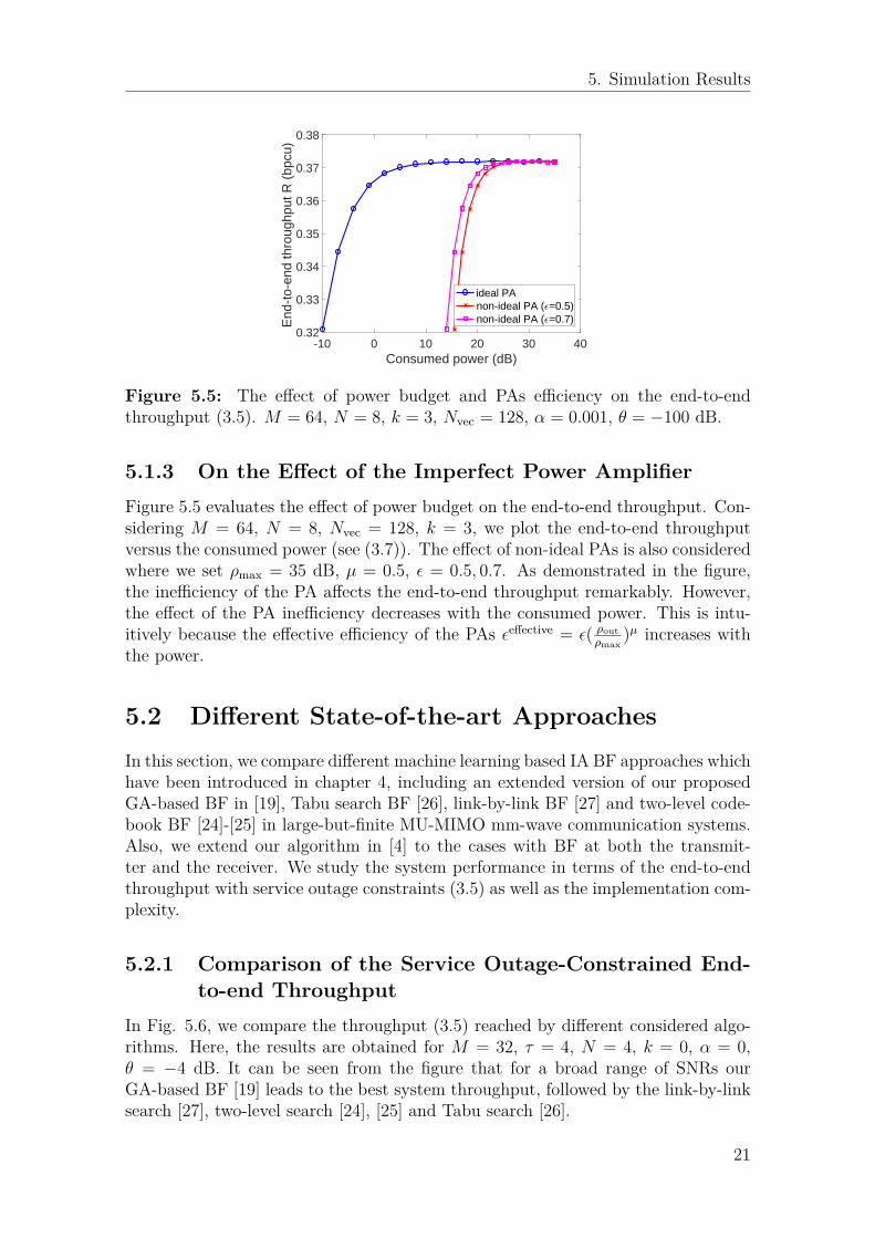
Figure 5.5: The effect of power budget and PAs efficiency on the end-to-endthroughput (3.5). M = 64, N = 8, k = 3, Nvec = 128, α = 0.001, θ = −100 dB.
5.1.3 On the Effect of the Imperfect Power AmplifierFigure 5.5 evaluates the effect of power budget on the end-to-end throughput. Con-sidering M = 64, N = 8, Nvec = 128, k = 3, we plot the end-to-end throughputversus the consumed power (see (3.7)). The effect of non-ideal PAs is also consideredwhere we set ρmax = 35 dB, µ = 0.5, ε = 0.5, 0.7. As demonstrated in the figure,the inefficiency of the PA affects the end-to-end throughput remarkably. However,the effect of the PA inefficiency decreases with the consumed power. This is intu-itively because the effective efficiency of the PAs εeffective = ε( ρout
ρmax)µ increases with
the power.
5.2 Different State-of-the-art ApproachesIn this section, we compare different machine learning based IA BF approaches whichhave been introduced in chapter 4, including an extended version of our proposedGA-based BF in [19], Tabu search BF [26], link-by-link BF [27] and two-level code-book BF [24]-[25] in large-but-finite MU-MIMO mm-wave communication systems.Also, we extend our algorithm in [4] to the cases with BF at both the transmit-ter and the receiver. We study the system performance in terms of the end-to-endthroughput with service outage constraints (3.5) as well as the implementation com-plexity.
5.2.1 Comparison of the Service Outage-Constrained End-to-end Throughput
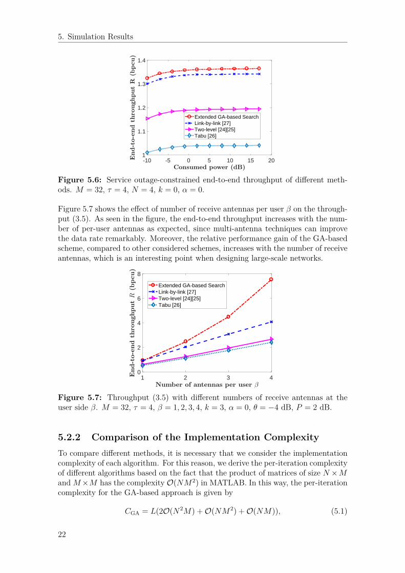
In Fig. 5.6, we compare the throughput (3.5) reached by different considered algo-rithms. Here, the results are obtained for M = 32, τ = 4, N = 4, k = 0, α = 0,θ = −4 dB. It can be seen from the figure that for a broad range of SNRs ourGA-based BF [19] leads to the best system throughput, followed by the link-by-linksearch [27], two-level search [24], [25] and Tabu search [26].
21
5. Simulation Results
-10 -5 0 5 10 15 201
1.1
1.2
1.3
1.4
Extended GA-based SearchLink-by-link [27]Two-level [24][25]Tabu [26]
Figure 5.6: Service outage-constrained end-to-end throughput of different meth-ods. M = 32, τ = 4, N = 4, k = 0, α = 0.
Figure 5.7 shows the effect of number of receive antennas per user β on the through-put (3.5). As seen in the figure, the end-to-end throughput increases with the num-ber of per-user antennas as expected, since multi-antenna techniques can improvethe data rate remarkably. Moreover, the relative performance gain of the GA-basedscheme, compared to other considered schemes, increases with the number of receiveantennas, which is an interesting point when designing large-scale networks.
1 2 3 40
2
4
6
8
Extended GA-based SearchLink-by-link [27]Two-level [24][25]Tabu [26]
Figure 5.7: Throughput (3.5) with different numbers of receive antennas at theuser side β. M = 32, τ = 4, β = 1, 2, 3, 4, k = 3, α = 0, θ = −4 dB, P = 2 dB.
5.2.2 Comparison of the Implementation ComplexityTo compare different methods, it is necessary that we consider the implementationcomplexity of each algorithm. For this reason, we derive the per-iteration complexityof different algorithms based on the fact that the product of matrices of size N ×MandM×M has the complexity O(NM2) in MATLAB. In this way, the per-iterationcomplexity for the GA-based approach is given by
CGA = L(2O(N2M) +O(NM2) +O(NM)), (5.1)
22

5. Simulation Results
and CTabu = CGA, Clink-by-link = τ ×CGA, Ctwo-level = 2×CGA. Here, L is the numberof beam selection sets within each iteration.
23

5. Simulation Results
24

6Summary of Included Papers
6.1 A Genetic Algorithm-based Beamforming Ap-proach for Delay-constrained Networks
Accepted in 15th International Symposium on Modeling and Optimization in Mobile,Ad Hoc, and Wireless Networks (Proc. IEEE WiOpt’ 2017), Telecom ParisTech,Paris, France, 15th-19th May, 2017.
In this paper, we study the performance of IA beamforming schemes in the caseswith large-but-finite number of transmit antennas and users. Particularly, we de-velop an efficient beamforming scheme using genetic algorithms. With the proposedalgorithm, the appropriate beamforming matrix is selected from a set of predefinedmatrices such that the network performance is optimized. Moreover, taking themm-wave communications characteristics and different metrics into account, we in-vestigate the effect of various parameters such as the number of antennas/receivers,beamforming resolution as well as hardware impairments on the system performance.As shown, our proposed algorithm is generic in the sense that it can be effectivelyapplied with different channel models, metrics and beamforming methods. Also, ourresults indicate that the proposed scheme can reach (almost) the same end-to-endthroughput as the exhaustive search-based optimal approach with considerably lessimplementation complexity.
For the simulation results, we consider the end-to-end throughput, the end-to-endservice outage-constrained throughput as well as the service outage probability. Inthis way, we take the algorithm running time into account and, as opposed to con-ventional iterative schemes, the system performance is not necessarily improved insuccessive iterations. Instead, as shown via simulations, the maximum throughputis achieved with few iterations, i.e., by picking up a suboptimal beamforming ap-proach, and using the remaining time for information transmission.
The simulation results show that 1) the proposed scheme can reach (almost) thesame performance as in the exhaustive search-based scheme with considerably lessimplementation complexity. Moreover, 2) non-ideal PAs affect the system perfor-mance significantly and should be carefully considered/compensated in the networkdesign, and 3) the network throughput increases almost linearly with the numberof codebook vectors. 4) The proposed algorithm is effectively applicable for variousconvex and non-convex performance metrics. 5) In general, the users service out-
25

6. Summary of Included Papers
age constraints affect the end-to-end throughput remarkably, while the effect of theconstraint decreases at high signal-to-noise ratios (SNRs).
6.2 A Comparison of IA Beamforming Algorithmsfor Millimeter Wave Networks
Submitted to 2017 IEEE 86th Vehicular Technology Conference: VTC2017-Fall,24–27 September 2017, Toronto, Canada.1
In this paper, we extend our previously proposed GA-based beamforming schemeto include beamforming at both the transmitter and the receiver, and we comparethe system performance with alternative beamforming approaches in the mm-waveMU-MIMO networks. Taking the mm-wave communications characteristics andvarious metrics into account, we investigate the effect of different parameters suchas the number of transmit antennas/users/per-user receive antennas, beamformingresolution as well as hardware impairments on the system performance employingdifferent beamforming algorithms. As shown, our proposed GA-based approachperforms well in delay-constrained networks with multi-antenna users. Comparedto the considered state-of-the- art schemes, our method reaches the highest serviceoutage- constrained end-to-end throughput with considerably less implementationcomplexity.
1To be attached in this report after the VTC review.
26
7Future Work
The main contribution of this thesis is to study, understand and design efficient IABF schemes for large-but-finite MU-MIMO networks. However, as a relatively broadtopic, there are many other interesting directions for the future work:
• Present a comprehensive picture of how the overall network access procedureshould be,
• Extend our beam selection method to the cases with digital/hybrid BF schemes,• Test our algorithm with realistic channel models and more specific access
threshold in the mm-wave bands,• Invent novel transmission and reception techniques using large antenna ar-
rays for multi-node mm-wave systems employing base station cooperation andrelaying for mobile users.
27

7. Future Work
28

Bibliography
[1] N. Alliance, “NGMN 5G white paper,” Next Generation Mobile Networks,White paper, Feb. 2015. [Online]. Available: https://www.ngmn.org/uploads/media/NGMN_5G_White_Paper_V1_0.pdf
[2] A. Osseiran et al., “Scenarios for 5G mobile and wireless communications: thevision of the METIS project,” IEEE Commun. Mag., vol. 52, no. 5, pp. 26–35,May. 2014.
[3] B. D. Van Veen and K. M. Buckley, “Beamforming: A versatile approach tospatial filtering,” IEEE ASSP Mag., vol. 5, no. 2, pp. 4–24, Aug. 1988.
[4] E. Dahlman, S. Parkvall, J. Skold, and P. Beming, 3G evolution: HSPA andLTE for mobile broadband. Academic press, 2010.
[5] F. Sohrabi and W. Yu, “Hybrid digital and analog beamforming design forlarge-scale antenna arrays,” IEEE J. Sel. Topics Signal Process., vol. 10, no. 3,pp. 501–513, Jan. 2016.
[6] C. N. Barati, S. A. Hosseini, M. Mezzavilla, T. Korakis, S. S. Panwar, S. Ran-gan, and M. Zorzi, “Initial Access in Millimeter Wave Cellular Systems,” IEEETrans. Wireless Commun., vol. 15, no. 12, pp. 7926–7940, Dec. 2016.
[7] J. P. Gilb, “IEEE Standards 802.15. 3c?–Part 15.3: wireless medium accesscontrol (MAC) and physical layer (PHY) specifications for high rate wirelesspersonal area networks (WPANs) Amendment 2: millimeter-wave-based alter-native physical layer extension [S],” IEEE Computer Society, New York, 2009.
[8] C. Cordeiro et al., “IEEE P802. 11 Wireless LANs, PHY/MAC Complete Pro-posal Specification (IEEE 802.11-10/0433r2),” 2010.
[9] H. Rate, “GHz PHY, MAC and PALs, Standard ECMA-387,” Dec. 2010.[10] V. Desai, L. Krzymien, P. Sartori, W. Xiao, A. Soong, and A. Alkhateeb, “Ini-
tial beamforming for mmwave communications,” in Proc. IEEE Asilomar’2014,CA, USA, Nov. 2014, pp. 1926–1930.
[11] C. N. Barati, S. A. Hosseini, S. Rangan, P. Liu, T. Korakis, S. S. Panwar,and T. S. Rappaport, “Directional cell discovery in millimeter wave cellularnetworks,” IEEE Trans. Wireless Commun., vol. 14, no. 12, pp. 6664–6678,Jul. 2015.
[12] Y. Qi and M. Nekovee, “Coordinated Initial Access in Millimetre Wave Stan-dalone Networks,” Millimeter-wave Networking Workshop (mmNet 2016), May.2016.
[13] Y. Li, J. G. Andrews, F. Baccelli, T. D. Novlan, and C. Zhang, “Designand Analysis of Initial Access in Millimeter Wave Cellular Networks,”Submitted to IEEE Trans. Wireless Commun., Mar. 2017. [Online]. Available:arXiv:1609.05582
29

Bibliography
[14] A. Alkhateeb, R. W. Heath, and G. Leus, “Achievable rates of multi-user mil-limeter wave systems with hybrid precoding,” in Proc. IEEE ICCW’2015, Lon-don, UK, Jun. 2015, pp. 1232–1237.
[15] H. Shokri-Ghadikolaei, C. Fischione, G. Fodor, P. Popovski, and M. Zorzi,“Millimeter wave cellular networks: A MAC layer perspective,” IEEE Trans.Commun., vol. 63, no. 10, pp. 3437–3458, Oct. 2015.
[16] M. Giordani, M. Mezzavilla, C. N. Barati, S. Rangan, and M. Zorzi, “Compar-ative analysis of initial access techniques in 5G mmwave cellular networks,” inProc. IEEE CISS’2016, Princeton University, Princeton, NJ 08544, Mar. 2016,pp. 268–273.
[17] M. Giordani, M. Mezzavilla, and M. Zorzi, “Initial access in 5G mmWave cel-lular networks,” IEEE Commun. Mag., vol. 54, no. 11, pp. 40–47, Nov. 2016.
[18] Y. Li, J. G. Andrews, F. Baccelli, T. D. Novlan, and J. Zhang, “On the initialaccess design in millimeter wave cellular networks,” in Proc. IEEE GLOBE-COM’2016, Washington, USA, Dec. 2016, pp. 1–6.
[19] H. Guo, B. Makki, and T. Svensson, “A Genetic Algorithm-based BeamformingApproach for Delay-constrained Networks,” in Proc. IEEE WiOpt’2017, Paris,France, May. 2017. [Online]. Available: arXiv:1703.03792
[20] B. Makki, T. Svensson, G. Cocco, T. de Cola, and S. Erl, “On the throughputof the return-link multi-beam satellite systems using genetic algorithm-basedschedulers,” in Proc. IEEE ICC’2015, London, UK, Jun. 2015, pp. 838–843.
[21] B. Makki, A. Ide, T. Svensson, T. Eriksson, and M.-S. Alouini, “A GeneticAlgorithm-based Antenna Selection Approach for Large-but-Finite MIMO Net-works,” IEEE Trans. Veh. Technol., Dec. 2016.
[22] V. Raghavan, J. Cezanne, S. Subramanian, A. Sampath, and O. Koymen,“Beamforming tradeoffs for initial UE discovery in millimeter-wave MIMO sys-tems,” IEEE J. Sel. Topics Signal Process., vol. 10, no. 3, pp. 543–559, Jan.2016.
[23] L. Zhou and Y. Ohashi, “Efficient codebook-based MIMO beamforming formillimeter-wave WLANs,” in Proc. IEEE PIMRC’2012, Sydney, Australia,Sept. 2012, pp. 1885–1889.
[24] S. Hur, T. Kim, D. J. Love, J. V. Krogmeier, T. A. Thomas, and A. Ghosh,“Multilevel millimeter wave beamforming for wireless backhaul,” in Proc. IEEEGC Wkshps’2011, Houston, Texas, USA, Dec. 2011, pp. 253–257.
[25] L. Chen, Y. Yang, X. Chen, and W. Wang, “Multi-stage beamforming codebookfor 60GHz WPAN,” in Proc. IEEE ICST’2011, Harbin, China, Aug. 2011, pp.361–365.
[26] X. Gao, L. Dai, C. Yuen, and Z. Wang, “Turbo-like beamforming based on Tabusearch algorithm for millimeter-wave massive MIMO systems,” IEEE Trans.Veh. Technol., vol. 65, no. 7, pp. 5731–5737, Jul. 2016.
[27] J. Qiao, X. Shen, J. W. Mark, and Y. He, “MAC-layer concurrent beamform-ing protocol for indoor millimeter-wave networks,” IEEE Trans. Veh. Technol.,vol. 64, no. 1, pp. 327–338, Jan. 2015.
[28] J. Singh and S. Ramakrishna, “On the feasibility of codebook-based beamform-ing in millimeter wave systems with multiple antenna arrays,” IEEE Trans.Wireless Commun., vol. 14, no. 5, pp. 2670–2683, Jan. 2015.
30

Bibliography
[29] C. Cordeiro, D. Akhmetov, and M. Park, “IEEE 802.11 ad: Introduction andperformance evaluation of the first multi-Gbps WiFi technology,” in Proceedingsof the 2010 ACM international workshop on mmWave communications: fromcircuits to networks, Chicago, IL, USA, 2010, pp. 3–8.
[30] L. Wan, X. Zhong, Y. Zheng, and S. Mei, “Adaptive codebook for limitedfeedback MIMO system,” in Proc. IEEE IFIP’2009, Cairo, Egypt, Apr. 2009,pp. 1–5.
[31] J. Choi, “Beam selection in mm-Wave multiuser MIMO systems using com-pressive sensing,” IEEE Trans. Commun., vol. 63, no. 8, pp. 2936–2947, Jun.2015.
[32] O. El Ayach, S. Rajagopal, S. Abu-Surra, Z. Pi, and R. W. Heath, “Spatiallysparse precoding in millimeter wave MIMO systems,” IEEE Trans. WirelessCommun., vol. 13, no. 3, pp. 1499–1513, Mar. 2014.
[33] B. Li, Z. Zhou, W. Zou, X. Sun, and G. Du, “On the efficient beamformingtraining for 60GHz wireless personal area networks,” IEEE Trans. WirelessCommun., vol. 12, no. 2, pp. 504–515, Feb. 2013.
[34] H.-H. Lee and Y.-C. Ko, “Low complexity codebook-based beamforming forMIMO-OFDM systems in millimeter-wave WPAN,” IEEE Trans. WirelessCommun., vol. 10, no. 11, pp. 3607–3612, Nov. 2011.
[35] B. Makki, T. Svensson, T. Eriksson, and M.-S. Alouini, “On the Required Num-ber of Antennas in a Point-to-Point Large-but-Finite MIMO System: Outage-Limited Scenario,” IEEE Trans. Commun., vol. 64, no. 5, pp. 1968–1983, May.2016.
[36] D. Persson, T. Eriksson, and E. G. Larsson, “Amplifier-aware multiple-inputsingle-output capacity,” IEEE Trans. Commun., vol. 62, no. 3, pp. 913–919,Jan. 2014.

Bibliography

Part II
Included Papers


A Genetic Algorithm-based Beamforming Approachfor Delay-constrained Networks
Hao Guo, Behrooz Makki, Tommy SvenssonDepartment of Signals and Systems, Chalmers University of Technology, Gothenburg, Sweden
[email protected], {behrooz.makki, tommy.svensson}@chalmers.se
Abstract—In this paper, we study the performance of initialaccess beamforming schemes in the cases with large but finitenumber of transmit antennas and users. Particularly, we developan efficient beamforming scheme using genetic algorithms. More-over, taking the millimeter wave communication characteristicsand different metrics into account, we investigate the effectof various parameters such as number of antennas/receivers,beamforming resolution as well as hardware impairments on thesystem performance. As shown, our proposed algorithm is genericin the sense that it can be effectively applied with different chan-nel models, metrics and beamforming methods. Also, our resultsindicate that the proposed scheme can reach (almost) the sameend-to-end throughput as the exhaustive search-based optimalapproach with considerably less implementation complexity.
I. INTRODUCTION
Developing key technical components and concepts formillimeter wave (MMW) communications in the range of6-100 GHz is of interest for 5G. Different works have es-timated/measured the channel characteristics in such MMWfrequency bands [1]–[4]. The use of such high frequenciesfor mobile communications is challenging but necessary forsupporting 5G which targets for peak data rates in the orderof 10-100 Gbps with low end-to-end latencies (down to 1 ms)[5].
Due to peak power limitation and high path loss in MMWcommunications, there is a need for directional transmissions.Fortunately, the physical size of antennas at MMW frequencybands is small so that it is possible to use large antennaarrays and perform beamforming [3] [4]. For typical wirelesssystems, beamforming is performed by employing precodingwith channel state information (CSI) feedback or estimationafter the control link is established. However, even with theextended coverage from beamforming, the coverage range forMMW frequencies is typically small due to high pathloss.As a result, we need to employ beamforming also on initialaccess (IA) channels. This calls for the need to design novelIA procedures.
During the MMW initial access procedure, beamformingis different from the conventional one because it is hard toacquire CSI. Different works have been recently presented onboth physical architecture and procedural algorithm to solvethe problem (see Section II for literature review). However, inthese works either the initial access algorithms are designedfor specific metrics, channel models, and precoding schemesor their implementation complexity grows significantly withthe number of antennas/users. Moreover, the running delay
of the algorithm is an important issue which has been rarelyconsidered in the performance evaluations.
In this paper, we study the performance of large-but-finitemultiple-input-multiple-output (MIMO) MMW networks us-ing codebook-based beamforming. The contributions of thepaper are two-fold. First, we propose an efficient genetic al-gorithm (GA)-based approach for initial access beamforming.With the proposed algorithm, the appropriate beamformingmatrix is selected from a set of predefined matrices suchthat the network performance is optimized. As we show,our proposed scheme is generic in the sense that it can beimplemented in the cases with different channel models, beam-forming methods as well as optimization metrics. Second, weevaluate the performance of the beamforning-based MIMOnetworks for different parameters such as hardware impair-ments, different channel models, beamforming resolution andnumber of antennas/receivers.
For the simulation results, we consider the end-to-end throughput, the end-to-end service outage-constrainedthroughput as well as the service outage probability. In thisway, we take the algorithm running time into account and,as opposed to conventional iterative schemes, the system per-formance is not necessarily improved in successive iterations.Instead, as shown via simulations, the maximum throughput isachieved with few iterations, i.e., by picking up a suboptimalbeamforming approach, and using the remaining time forinformation transmission.
The simulation results show that 1) the proposed schemecan reach (almost) the same performance as in the exhaustivesearch-based scheme with considerably less implementationcomplexity. Moreover, 2) non-ideal power amplifiers (PAs)affect the system performance significantly and should becarefully considered/compensated in the network design, and3) the network throughput increases almost linearly withthe number of codebook vectors. 4) The proposed algorithmis effectively applicable for various convex and non-convexperformance metrics. 5) In general, the users service outageconstraints affect the end-to-end throughput remarkably, whilethe effect of the constraint decreases at high signal-to-noiseratios (SNRs). 6) In practice, taking the algorithm runningdelay into account, the maximum end-to-end throughput isreached by dedicating a small fraction of the packet periodto finding the suboptimal beamforming solution and using therest of the packet for data transmission.

II. LITERATURE REVIEW
In this section, we review the recent results on initial access.The readers mainly interested in the technical discussions canskip this part and go to Sections III-V where we presentthe system model, our proposed algorithm and the simulationresults, respectively. Beamforming techniques at MMW fre-quencies have been widely investigated and led to standarddevelopments such as IEEE 802.15.3c (TG3c) [6], IEEE802.11ad (TGad) [7] and ECMA-387 [8]. In wireless local areanetworks (WLANs), a one-sided beam search strategy using abeamforming codebook has been employed to establish initialalignment between large array antennas [9].
For mobile communication systems, on the other hand, thereare few works on initial access beamforming. In general, mostof the presented works are based on multi-level/greedy searchalgorithms and utilize the sparse nature of the MMW channel.Several issues for initial access beamforming in MMW fre-quencies are presented in [10] and a fast-discovery hierarchicalsearch method is proposed. Moreover, [11] designs a novelgreedy-geometric algorithm to synthesize antenna patterns fea-turing desired beamwidth. In [12], a survey of several recentlyproposed IA techniques is provided. Then, [13] performs IAfor clustered MMW small cells with a power-delay-profile-based approach to reduce the IA set up time. Also, [14] showsthe significant benefits of using low-resolution fully digitalarchitectures during IA, in comparison to single stream analogbeamforming.
In MMW multiuser multiple-input-single-output (MISO)downlink systems, an opportunistic random beamformingtechnique is provided in [15]. Also, [16] develops low-complexity algorithms for optimizing the choice of beamform-ing directions, premised on the sparse multipath structure ofthe MMW channel. Then, [17] studies a low-complexity beamselection method by designing low-cost analog beamformers.This beam selection method can be carried out without explicitchannel estimation. A directional cell discovery method is pro-posed in [18] where the BS periodically transmits synchroniza-tion signals to scan the whole angular space in time-varyingrandom directions. In [19], MMW precoder design is formu-lated as a sparsity-constrained signal recovery problem, andan algorithmic solution with orthogonal matching pursuit isproposed. Finally, [20] proposes a hybrid precoding algorithmbased on a low training overhead channel estimation methodto overcome the hardware constraints in MMW analog-onlybeamforming systems.
Considering codebook-based beamforming, a broadcast-based solution for MMW systems is proposed in [21], wherelimited feedback-type directional codebooks are used for thebeamforming procedure. Moreover, [22] studies concurrentbeamforming issues for achieving high capacity in indoorMMW networks. In [23], an efficient beam alignment tech-nique is designed which uses adaptive subspace samplingand hierarchical beam codebooks. With pre-specified beamcodebooks, [24] proposes a Rosenbrock numerical algorithmto accelerate the beam-switch process which is modeled as a
Fig. 1. MMW multiuser MIMO system model.
2-D plane optimization problem. Also, [25] adopts the discreteFourier transform (DFT)-based codebooks and proposes an ef-ficient iterative antenna vector training algorithm. Finally, [26]provides a codebook-based beamforming scheme with multi-level training and level-adaptive antenna selection, which canbe used for MIMO orthogonal frequency division multiplexing(OFDM) systems in MMW wireless personal area networks(WPANs).
There are previous works using the GA-based selectionapproach. For instance, [27] elaborates on the performance ofscheduling in the return-link of a multi-beam satellite system.Moreover, [28] uses a genetic algorithm to achieve a near-optimal array gain in all directions during codebook-basedbeamforming.
III. SYSTEM MODEL
We use a multiuser MIMO setup with M transmit antennasin a BS and N single-antenna users (see Fig. 1). At each timeslot t, the received signal can be described as
Y(t) =
√P
MH(t)V(t)X(t) + Z(t), (1)
where P is the total power budget, H(t) ∈ CN×M is thechannel matrix, X(t) ∈ CM×1 is the intended message signal,V(t) ∈ CM×M is the precoding matrix, and Z(t) ∈ CN×1denotes the independent and identically distributed (IID) Gaus-sian noise matrix. For simplicity, we drop time index t in thefollowing.
The channel H is modeled by
H =
√k
k + 1HLOS +
√1
k + 1HNLOS, (2)
where HLOS and HNLOS denote the line-of-sight (LOS) andnon-line-of-sight (NLOS) components of the channel. Also,k controls the relative strength of the LOS and NLOS com-ponents. It can be seen that k = 0 represents an NLOSchannel, while k → ∞ gives a LOS condition. Also, theNLOS component is assumed to follow complex Gaussiandistribution.

Fig. 2. Schematic of a packet transmission period.
A. Initial Beamforming Procedure
Conventional beamforming procedure schemes utilize CSIto generate the precoding matrix. However, it is almost impos-sible to acquire CSI in large scale MMW systems. Instead, weperform codebook-based beamforming, which means selectinga precoding matrix V out of a predefined codebook W atthe BS, sending test signal and finally making decisions ontransmit beam patterns based on users’ feedback about theirreceived metrics. The IA will be finished as soon as a stablecontrol link is established. The time structure for the packettransmission can be seen in Fig. 2, where part of the packetperiod is dedicated to design the appropriate beams and the restis used for data transmission. Thus, we need to find a balancebetween beamforming time and data transmission period bypicking up a suboptimal beamforming approach and using theremaining time for information transmission. Here, we use aDFT-based codebook [29] defined as
W = |w(m,u)| = |e−j2π(m−1)(u−1)/Nvec |,m = 1, 2, ...,M, u = 1, 2, ..., Nvec, (3)
where Nvec ≥ M is the number of codebook vectors. Thiscodebook can achieve uniform antenna gain in all directions,however, as seen in the following, the proposed algorithm canbe implemented for different codebook definitions.
B. Performance Metrics
As seen in the following, the proposed GA-based algorithmis generic, in the sense that it can be effectively applied forvarious performance metrics. For the simulations, however,we consider the end-to-end throughput, the service outage-constrained throughput and the service outage probabilitydefined as follows.
Set Nit to be the maximum possible number of iterationswhich is decided by designer. Considering the K-th iterationround of the algorithm, K=1, 2,..., Nit, the end-to-end through-put in bit-per-channel-use (bpcu) is defined as
R(K) = (1− αK)
N∑i=1
rKi ,
rKi = log2
(1 + SINRKi
). (4)
Here, α is the relative delay cost for running each iteration ofthe algorithm which fulfills αNit < 1. Also,
SINRKi =PM gi,i
BN0 +PM
∑Ni 6=j gi,j
(5)
is the signal-to-interference-plus-noise ratio (SINR) of user iin iteration K, in which gi,j is the (i, j)-th element of the
matrix GK = |HVK |2 (and G is referred to as the channelgain throughout the paper), B is the system bandwidth and N0
is the power spectral density of the noise. Thus, rKi denotesthe achievable rate of user i at the end of the K-th iterationof the algorithm. In this way, as opposed to, e.g., [14, Eq.1] [17, Eq. 43] [19, Eq. 3], [22, Eq. 3], [24, Eq. 5] [26, Eq.5], we take the algorithm running delay into account. Thus,there is a trade-off between finding the optimal beamformingmatrices and reducing the data transmission time slot, and thehighest throughput may be achieved by few iterations, i.e., arough estimation of the optimal beamformer. To simplify thepresentations, we set BN0 = 1. As a result, the power P (indB, 10 log10 P ) denotes the SNR as well.
In different applications, it may be required to serve theusers with some minimum required rates, otherwise serviceoutage occurs. For this reason, we analyze the end-to-endservice outage-constrained throughput defined as
R̃(K) = (1− αK)
N∑i=1
riU(ri, log2(1 + θ)),
U(ri, log2(1 + θ)) =
{1 ri ≥ log2(1 + θ)0 ri < log2(1 + θ),
(6)
where log2(1 + θ) is the minimum rate required by the usersand θ represents the minimum required SINR of the users. Thisis interesting for applications where each user is required tohave a minimum rate log2(1+ θ). Among our motivations forthe service outage-constrained throughput analysis is to high-light the effectiveness of the proposed algorithm in optimizingthe non-convex criteria.
Finally, as another performance metric, we study the serviceoutage probability which is defined as
φ = Pr(ri < log2(1 + θ),∀i). (7)
C. On the Effect of Power Amplifier
In multi-antenna systems, when the number of transmit an-tennas increases, the efficiency of radio-frequency PAs shouldbe taken into account. Here, we consider the state-of-the-artPA efficiency model [30, Eq. 13], [31, Eq. 3]
ρcons =ρµmax
ε× ρµ−1out(8)
where ρcons, ρout, ρmax refer to the consumed power, outputpower and maximum output power of the PA, respectively.Also, ε ∈ [0, 1] is the power efficiency and µ ∈ [0, 1] is aparameter which depends on the PA classes. Note that settingε = 1, Pmax = ∞ and µ = 0 represents the special case withan ideal PA.
IV. ALGORITHM DESCRIPTION
We use a GA-based approach for beam selection duringIA beamforming and details are explained in Algorithm 1.The algorithm starts by getting L possible beam selection setsrandomly and each of them means a certain beam formed bytransmit antennas, i.e., a submatrix of the codebook. During

each iteration, we determine the best selection result, named asthe Queen, based on our objective metrics. For instance, wechoose the beamforming matrix with the highest end-to-endthroughput if (4) is considered as the objective function. Next,we keep the Queen and regenerate S < L matrices around theQueen. This can be done by making small changes to theQueen such as changing a number of columns in the Queenmatrix. In the simulations, we replace 10% of the columnsof the Queen by other random columns from the codebook.Finally, during each iteration L−S−1 beamforming matricesare selected randomly. After Nit iterations, considered by thealgorithm designer, the Queen is returned as the beam selectionrule in the considered time slot.
Algorithm 1 GA-based Beam Selection AlgorithmIn each time slot with instantaneous channel realization H ∈CN×M , do the followings:
I. Consider L, e.g., L = 10, sets of beamformingmatrices Vl, l = 1,..., L, randomly selected from thepre-defined codebook W.
II. For each Vl, evaluate the instantaneous value of theobjective metric Rl, l = 1,..., L, for example end-to-end throughput (4).
III. Selection: Find the best beamforming matrix which re-sults in the best value of the considered metric, namedas the Queen, e.g., Vq satisfies R(Vl) ≤ R(Vq), ∀l = 1,..., L if the end-to-end throughput is the objectivefunction.
IV. V1 ← VqV. Create S � L, e.g., S = 5, beamforming matrices
Vnews , s = 1,..., S, around the Queen V1. These sets
are generated by making small changes in the Queen.VI. Vs+1 ← Vnew
s , s = 1,..., S.VII. Go back to Step II and run for Nit iterations, Nit is a
fixed number decided by designer.Return the final Queen as the beam selection rule for thecurrent time slot.
As demonstrated, the algorithm is generic in the sense thatit is independent of the channel model, objective function orprecoding matrix, thus this can be used in different scenariosand as a benchmark for comparison of different IA schemes.Also, our proposed algorithm converges to the (sub)optimalvalue of the considered metrics using few iterations. Therefore,the proposed algorithm can be useful in IA beamformingwhere the delay is one of the most important factors.
V. SIMULATION RESULTS
For the simulation results, we consider the channel modeldescribed by (2), with k = 0, 1, 2, 3, 10. We have checkedthe results for a broad range of parameter settings. How-ever, due to space limits and because they follow the samequalitative behaviors as in Fig. 3-9, they are not reported.The initial access beamforming process is performed basedon the codebook defined in (3). However, one can use thealgorithm for different beamforming schemes at the transmitter
0 200 400 600 800 10000
20
40
60
80
100
Re
lative
th
rou
gh
pu
t %
(a) System performance with delay (α = 0.001)
0 200 400 600 800 100070
75
80
85
90
95
100
Re
lative t
hro
ughp
ut
%
(b) System performance without delay (α = 0)
Fig. 3. Examples of the convergence process of the GA-based beamformingfor systems with (subplot a) and without (subplot b) delay cost of thealgorithm. M = 32, N = 8, Nvec = 128, P = 10 dB, k = 0.
and receivers. Except for Fig. 3 which shows an example ofthe algorithm procedure by plotting the relative throughputν = R(K)
max∀K
R(K)%, for each point in the curves we run the
simulation for 104 different channel realizations of the NLOScomponent in (2). Then, the LOS component of the channel in(2) is set to HLOS(i, i) = β(1 + j), ∀i = 1, . . . ,min(M,N),HLOS(i, k) =
√MN−min(M,N)β2
min(M,N) (1 + j), ∀i 6= k or i =
k > min(M,N), j =√−1, which leads to |HLOS|2 = 1,
∀M,N, β. In the simulations we set β = 0.2. In all figures, theGA algorithm is run for sufficiently large number of iterationsuntil no performance improvement is observed. Then, TablesI-II show the average number of required iterations to reachthe (sub)optimal solution. Also, we set L = 10, S = 5 inAlgorithm 1. Finally, in all figures, except for Fig. 4, weconsider an ideal PA, i.e., set Pmax = ∞, µ = 0, ε = 1 in(8). The effect of imperfect PAs is studied in Fig. 4. In Figs.3-6 and Tables I-II, we consider the end-to-end throughput(4) as the performance metric. Throughput optimization witha service outage constraint, i.e., (6), is studied in Figs. 7-9.Finally, Table III studies the system performance in the case
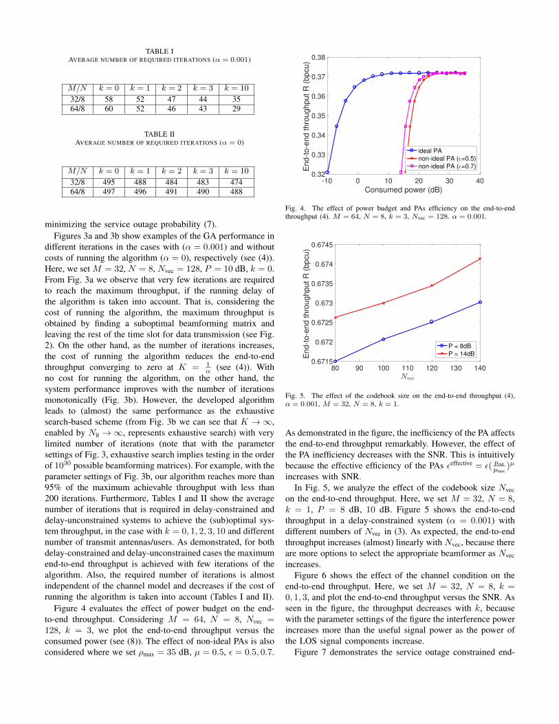
TABLE IAVERAGE NUMBER OF REQUIRED ITERATIONS (α = 0.001)
M/N k = 0 k = 1 k = 2 k = 3 k = 10
32/8 58 52 47 44 3564/8 60 52 46 43 29
TABLE IIAVERAGE NUMBER OF REQUIRED ITERATIONS (α = 0)
M/N k = 0 k = 1 k = 2 k = 3 k = 10
32/8 495 488 484 483 47464/8 497 496 491 490 488
minimizing the service outage probability (7).Figures 3a and 3b show examples of the GA performance in
different iterations in the cases with (α = 0.001) and withoutcosts of running the algorithm (α = 0), respectively (see (4)).Here, we set M = 32, N = 8, Nvec = 128, P = 10 dB, k = 0.From Fig. 3a we observe that very few iterations are requiredto reach the maximum throughput, if the running delay ofthe algorithm is taken into account. That is, considering thecost of running the algorithm, the maximum throughput isobtained by finding a suboptimal beamforming matrix andleaving the rest of the time slot for data transmission (see Fig.2). On the other hand, as the number of iterations increases,the cost of running the algorithm reduces the end-to-endthroughput converging to zero at K = 1
α (see (4)). Withno cost for running the algorithm, on the other hand, thesystem performance improves with the number of iterationsmonotonically (Fig. 3b). However, the developed algorithmleads to (almost) the same performance as the exhaustivesearch-based scheme (from Fig. 3b we can see that K →∞,enabled by Nit →∞, represents exhaustive search) with verylimited number of iterations (note that with the parametersettings of Fig. 3, exhaustive search implies testing in the orderof 1030 possible beamforming matrices). For example, with theparameter settings of Fig. 3b, our algorithm reaches more than95% of the maximum achievable throughput with less than200 iterations. Furthermore, Tables I and II show the averagenumber of iterations that is required in delay-constrained anddelay-unconstrained systems to achieve the (sub)optimal sys-tem throughput, in the case with k = 0, 1, 2, 3, 10 and differentnumber of transmit antennas/users. As demonstrated, for bothdelay-constrained and delay-unconstrained cases the maximumend-to-end throughput is achieved with few iterations of thealgorithm. Also, the required number of iterations is almostindependent of the channel model and decreases if the cost ofrunning the algorithm is taken into account (Tables I and II).
Figure 4 evaluates the effect of power budget on the end-to-end throughput. Considering M = 64, N = 8, Nvec =128, k = 3, we plot the end-to-end throughput versus theconsumed power (see (8)). The effect of non-ideal PAs is alsoconsidered where we set ρmax = 35 dB, µ = 0.5, ε = 0.5, 0.7.
-10 0 10 20 30 40
Consumed power (dB)
0.32
0.33
0.34
0.35
0.36
0.37
0.38
En
d-t
o-e
nd
th
rou
ghp
ut
R (
bp
cu
)
ideal PA
non-ideal PA ( =0.5)
non-ideal PA ( =0.7)
Fig. 4. The effect of power budget and PAs efficiency on the end-to-endthroughput (4). M = 64, N = 8, k = 3, Nvec = 128. α = 0.001.
80 90 100 110 120 130 1400.6715
0.672
0.6725
0.673
0.6735
0.674
0.6745
End
-to-e
nd
th
roug
hpu
t R
(b
pcu)
P = 8dB
P = 14dB
Fig. 5. The effect of the codebook size on the end-to-end throughput (4),α = 0.001, M = 32, N = 8, k = 1.
As demonstrated in the figure, the inefficiency of the PA affectsthe end-to-end throughput remarkably. However, the effect ofthe PA inefficiency decreases with the SNR. This is intuitivelybecause the effective efficiency of the PAs εeffective = ε( pout
pmax)µ
increases with SNR.In Fig. 5, we analyze the effect of the codebook size Nvec
on the end-to-end throughput. Here, we set M = 32, N = 8,k = 1, P = 8 dB, 10 dB. Figure 5 shows the end-to-endthroughput in a delay-constrained system (α = 0.001) withdifferent numbers of Nvec in (3). As expected, the end-to-endthroughput increases (almost) linearly with Nvec, because thereare more options to select the appropriate beamformer as Nvecincreases.
Figure 6 shows the effect of the channel condition on theend-to-end throughput. Here, we set M = 32, N = 8, k =0, 1, 3, and plot the end-to-end throughput versus the SNR. Asseen in the figure, the throughput decreases with k, becausewith the parameter settings of the figure the interference powerincreases more than the useful signal power as the power ofthe LOS signal components increase.
Figure 7 demonstrates the service outage constrained end-

-10 0 10 20 30 40
SNR (dB)
0.5
0.55
0.6
0.65
0.7
0.75
0.8
0.85E
nd
-to
-en
d th
rou
gh
put
R (
bp
cu
)
Fig. 6. The effect of different channel conditions on the end-to-end throughput(4), M = 32, N = 8, α = 0.001.
-10 -5 0 5 10 15 20
SNR (dB)
0
0.2
0.4
0.6
0.8
1
Serv
ice o
uta
ge c
on
str
ain
ed
end
-to-e
nd
th
rou
gh
pu
t R
(bp
cu
)
=-100 dB
=-4 dB
=-2 dB
=0 dB
Fig. 7. Service outage constrained end-to-end throughput with M = 32,N = 8, k = 0, Nvec = 128, θ = −100,−4,−2, 0 dB.
0 0.05 0.1 0.15 0.2 0.25 0.3
Service outage constrained
per-user throughput (bpcu)
0
0.2
0.4
0.6
0.8
1
CD
F o
f th
e p
er-
use
r th
roug
hput
= -100dB
= -4dB
= -2dB
= 0dB
Fig. 8. CDF of service outage constrained per-user throughput in the casesoptimizing (6), M = 32, N = 8, k = 0, Nvec = 128, θ = −100,−4,−2, 0dB.
to-end throughput (6) for different values of required receivedSNR thresholds θ in (6). Also, Fig. 8 shows the cumulativedistribution function (CDF) of the users achievable rates for
-10 -5 0 5 10 15 20
SNR (dB)
10-3
10-2
10-1
100
Se
rvic
e o
uta
ge p
rob
ab
ility
= -4 dB
= -2 dB
= 0 dB
Fig. 9. Service outage probability in the cases optimizing (6), M = 32,N = 8, k = 0, Nvec = 128, θ = −4,−2, 0 dB.
different service outage constraints. Here, the results are pre-sented for N = 8,M = 32, k = 0, Nvec = 128. Finally, Fig. 9studies the service outage probability in the cases optimizing(6). As demonstrated in the Figs. 7-8, the service outageconstraint affects the end-to-end and the per-user throughputsignificantly at low SNRs/severe service outage constraints.For instance, with the parameter settings of Fig. 8, more than50% of the users may receive data with rates less than 1 bpcu,corresponding to θ = 0 dB (see Fig. 8, (6)). However, theeffect of the service outage probability decreases as the SNRincreases or θ decreases (Figs. 7-9).
TABLE IIIAVERAGE NUMBER OF SERVED USERS IN SERVICE OUTAGE-CONSTRAINED
SYSTEMS
θ (dB) -100 -4 -2 0 2Case1 8.00 7.14 6.82 6.49 6.15Case2 8.00 7.47 7.15 6.82 6.48
In Table III, we study the average number of served users inCase 1 and 2 where the service outage constrained throughput(6) and the service outage probability (7) are considered asthe optimization metric, respectively. Here, the results arepresented for M = 32, N = 8, k = 0, Nvec = 128. Asexpected, compared to Case 1 maximizing (6), the averagenumber of served users increases when the goal is to minimizethe service outage probability (Case 2). This is indeed at thecost of some end-to-end throughput loss. Finally, the averagenumber of served users increases as θ decreases, i.e., the usersminimum required rate decreases.
VI. CONCLUSION
We studied the performance of initial access beamformingin delay-constrained networks. Considering delay cost of thebeamforming procedure, we evaluated the end-to-end through-put as well as the service outage-constrained system perfor-mance under different parameter settings. We developed a GA-based beam selection approach which can reach almost the

same throughput as in the exhaustive search-based approachwith relatively few iterations. Moreover, the proposed algo-rithm can be effectively applied for different channel models,performance metrics and beamforming schemes. Therefore,our proposed algorithm is suitable for delay-constrained sys-tems and it can be practically implemented in the future.Then, non-ideal PA affects the system performance remark-ably, while its effect decreases at high SNR. Finally, theusers’ severe service outage constraints affect the end-to-endthroughput considerably, while its effect decreases at highSNRs. Comparison between different initial access techniquesis an interesting future work on which we are working.
ACKNOWLEDGMENT
The research leading to these results received funding fromthe European Commission H2020 programme under grantagreement n◦671650 (5G PPP mmMAGIC project), and fromthe Swedish Governmental Agency for Innovation Systems(VINNOVA) within the VINN Excellence Center Chase.
REFERENCES
[1] T. Bai, A. Alkhateeb, and R. W. Heath, “Coverage and capacity ofmillimeter-wave cellular networks,” IEEE Commun. Mag., vol. 52, no. 9,pp. 70–77, Sept. 2014.
[2] G. R. MacCartney, J. Zhang, S. Nie, and T. S. Rappaport, “Pathloss models for 5G millimeter wave propagation channels in urbanmicrocells,” in Proc. IEEE GLOBECOM’2013, Atlanta, GA, USA, Dec.2013, pp. 3948–3953.
[3] Z. Pi and F. Khan, “An introduction to millimeter-wave mobile broad-band systems,” IEEE Commun. Mag., vol. 49, no. 6, pp. 101–107, Jun.2011.
[4] S. Sun, G. R. MacCartney, M. K. Samimi, S. Nie, and T. S. Rappaport,“Millimeter wave multi-beam antenna combining for 5G cellular linkimprovement in new york city,” in Proc. IEEE ICC’2014, Sydney,Australia, Jun. 2014, pp. 5468–5473.
[5] M. Cudak, A. Ghosh, T. Kovarik, R. Ratasuk, T. A. Thomas, F. W.Vook, and P. Moorut, “Moving towards mmwave-based beyond-4G (B-4G) technology,” in Proc. IEEE VTC’2013, Dresden, Germany, Jun.2013, pp. 1–5.
[6] J. P. Gilb, “IEEE standards 802.15. 3c–part 15.3: wireless medium accesscontrol (MAC) and physical layer (PHY) specifications for high ratewireless personal area networks (WPANs) amendment 2: millimeter-wave-based alternative physical layer extension [s],” IEEE ComputerSociety, New York, Aug. 2009.
[7] C. Cordeiro et al., “IEEE P802. 11 Wireless LANs, PHY/MAC Com-plete Proposal Specification (IEEE 802.11-10/0433r2),” May. 2010.
[8] H. Rate, “GHz PHY, MAC and PALs, Standard ECMA-387,ser. Link: https://www.ecma-international.org/publications/files/ECMA-ST/ECMA-387.pdf,” 2010.
[9] C. Cordeiro, D. Akhmetov, and M. Park, “IEEE 802.11 ad: introductionand performance evaluation of the first multi-gbps wifi technology,” inProc. IEEE mmCOM’2010 Chicago, IL, USA. ACM, Sept. 2010, pp.3–8.
[10] V. Desai, L. Krzymien, P. Sartori, W. Xiao, A. Soong, and A. Alkhateeb,“Initial beamforming for mmwave communications,” in Proc. IEEEACSSC’2014, Pacific Grove, CA, USA, Nov. 2014, pp. 1926–1930.
[11] J. Palacios, D. De Donno, D. Giustiniano, and J. Widmer, “Speeding upmmwave beam training through low-complexity hybrid transceivers,” inProc. IEEE PIMRC’2016, Valencia, Spain, Sept. 2016.
[12] M. Giordani, M. Mezzavilla, C. N. Barati, S. Rangan, and M. Zorzi,“Comparative analysis of initial access techniques in 5G mmwavecellular networks,” in 2016 Annual Conference on Information Scienceand Systems (CISS), Princeton University, Princeton, NJ 08544, Apr.2016, pp. 268–273.
[13] Y. Qi and M. Nekovee, “Coordinated initial access in millimetre wavestandalone networks,” Millimeter-wave Networking Workshop (mmNet2016), May. 2016.
[14] C. N. Barati, S. A. Hosseini, M. Mezzavilla, T. Korakis, S. S. Panwar,S. Rangan, and M. Zorzi, “Initial access in millimeter wave cellularsystems,” IEEE Trans. Wireless Commun., vol. 15, no. 12, pp. 7926–7940, Dec. 2016.
[15] G. Lee, Y. Sung, and J. Seo, “Randomly-directional beamformingin millimeter-wave multiuser MISO downlink,” IEEE Trans. WirelessCommun., vol. 15, no. 2, pp. 1086–1100, Sept. 2016.
[16] J. Singh and S. Ramakrishna, “On the feasibility of codebook-basedbeamforming in millimeter wave systems with multiple antenna arrays,”IEEE Trans. Wireless Commun., vol. 14, no. 5, pp. 2670–2683, Jan.2015.
[17] J. Choi, “Beam selection in mm-wave multiuser MIMO systems usingcompressive sensing,” IEEE Trans. Commun., vol. 63, no. 8, pp. 2936–2947, Jun. 2015.
[18] C. N. Barati, S. A. Hosseini, S. Rangan, P. Liu, T. Korakis, S. S. Panwar,and T. S. Rappaport, “Directional cell discovery in millimeter wavecellular networks,” IEEE Trans. Wireless Commun., vol. 14, no. 12, pp.6664–6678, Jul. 2015.
[19] O. El Ayach, S. Rajagopal, S. Abu-Surra, Z. Pi, and R. W. Heath,“Spatially sparse precoding in millimeter wave MIMO systems,” IEEETrans. Wireless Commun., vol. 13, no. 3, pp. 1499–1513, March. 2014.
[20] A. Alkhateeb, O. El Ayach, G. Leus, and R. W. Heath, “Channelestimation and hybrid precoding for millimeter wave cellular systems,”IEEE J. Sel. Topics Signal Process., vol. 8, no. 5, pp. 831–846, Oct.2014.
[21] V. Raghavan, J. Cezanne, S. Subramanian, A. Sampath, and O. Koymen,“Beamforming tradeoffs for initial UE discovery in millimeter-waveMIMO systems,” IEEE J. Sel. Topics Signal Process., vol. 10, no. 3,pp. 543–559, Jan. 2016.
[22] J. Qiao, X. Shen, J. W. Mark, and Y. He, “MAC-layer concurrentbeamforming protocol for indoor millimeter-wave networks,” IEEETrans. Veh. Technol, vol. 64, no. 1, pp. 327–338, Jan. 2015.
[23] S. Hur, T. Kim, D. J. Love, J. V. Krogmeier, T. A. Thomas, andA. Ghosh, “Millimeter wave beamforming for wireless backhaul andaccess in small cell networks,” IEEE Trans. Commun., vol. 61, no. 10,pp. 4391–4403, Oct. 2013.
[24] B. Li, Z. Zhou, W. Zou, X. Sun, and G. Du, “On the efficient beam-forming training for 60GHz wireless personal area networks,” IEEETrans. Wireless Commun., vol. 12, no. 2, pp. 504–515, Feb. 2013.
[25] L. Zhou and Y. Ohashi, “Efficient codebook-based MIMO beamformingfor millimeter-wave WLANs,” in Proc. IEEE PIMRC’2012, Sept. 2012,pp. 1885–1889.
[26] H.-H. Lee and Y.-C. Ko, “Low complexity codebook-based beamform-ing for MIMO-OFDM systems in millimeter-wave WPAN,” IEEE Trans.Wireless Commun., vol. 10, no. 11, pp. 3607–3612, Nov. 2011.
[27] B. Makki, T. Svensson, G. Cocco, T. de Cola, and S. Erl, “On thethroughput of the return-link multi-beam satellite systems using geneticalgorithm-based schedulers,” in Proc. IEEE ICC’2015, London, UK, Jun.2015, pp. 838–843.
[28] S. Payami, M. Shariat, M. Ghoraishi, and M. Dianati, “Effective RFcodebook design and channel estimation for millimeter wave commu-nication systems,” in Proc. IEEE ICCW’2015, London, UK, Jun. 2015,pp. 1226–1231.
[29] L. Wan, X. Zhong, Y. Zheng, and S. Mei, “Adaptive codebook for limitedfeedback MIMO system,” in Proc. IEEE WOCN’2009, Cairo, Egypt,Apr. 2009, pp. 1–5.
[30] B. Makki, T. Svensson, T. Eriksson, and M.-S. Alouini, “On the requirednumber of antennas in a point-to-point large-but-finite MIMO system:Outage-limited scenario,” IEEE Trans. Commun., vol. 64, no. 5, pp.1968–1983, May. 2016.
[31] D. Persson, T. Eriksson, and E. G. Larsson, “Amplifier-aware multiple-input single-output capacity,” IEEE Trans. Commun., vol. 62, no. 3, pp.913–919, Jan. 2014.