Ingex Modules and Configurationsingex.sourceforge.net/studio/IngexConfigurationGuide.pdfFile replay...
65
Ingex Modules and Configurations Copyright 2010 British Broadcasting Corporation All rights reserved 7th September 2010 - 1 -
Transcript of Ingex Modules and Configurationsingex.sourceforge.net/studio/IngexConfigurationGuide.pdfFile replay...

Ingex Modules and Configurations
Copyright 2010 British Broadcasting Corporation
All rights reserved
7th September 2010
- 1 -

Table of ContentsOverview.....................................................................................................................................4Ingex Modules.............................................................................................................................5Capture........................................................................................................................................6Recorder......................................................................................................................................7Recorder Controller.....................................................................................................................7Database......................................................................................................................................7Web Server..................................................................................................................................8Name Server................................................................................................................................8Player..........................................................................................................................................8Multicast Server..........................................................................................................................8Transfer Server............................................................................................................................9Vision mixer cut logger...............................................................................................................9Ingex monitoring.......................................................................................................................10System monitoring....................................................................................................................10Read this before the configurations...........................................................................................11Style...........................................................................................................................................11The configuration file ingex.conf..............................................................................................11HD/SD operation.......................................................................................................................12DNS...........................................................................................................................................12Modules that don't change their configuration..........................................................................13System Services........................................................................................................................13Capture format and buffers.......................................................................................................13Quad-Split.................................................................................................................................15Monitoring................................................................................................................................16Sending recordings to a remote file server................................................................................17Settings in the ingex.conf file...................................................................................................18Setting the transfer destinations................................................................................................19Mounting the file server............................................................................................................20Multicasting..............................................................................................................................21Setting in the ingex.conf file.....................................................................................................22Viewing the multicast streams..................................................................................................23Minimum Ingex system............................................................................................................25Settings in the ingex.conf file...................................................................................................25Other settings............................................................................................................................26File replay on the PC screen.....................................................................................................27Transfer to removable disc........................................................................................................27Controller sited remotely from recorder...................................................................................29Running Controller remotely using ssh....................................................................................29Running Recorder Control on a separate PC............................................................................31Configuration of the Recorder PC............................................................................................32Configuration of the Controller PC...........................................................................................32Adding inputs by using multiple recorder PCs.........................................................................35Configuration of the first Ingex PC...........................................................................................36Configuration of the second Ingex PC......................................................................................36Multiple recorders on the same PC...........................................................................................39Configuration of the first Ingex PC...........................................................................................40Configuration of the second Ingex PC......................................................................................42Configuration of the controller PC............................................................................................43Database and Name Server on a central server.........................................................................45Multiple name servers and databases........................................................................................48
- 2 -
Settings on the Ingex PCs.........................................................................................................49Settings on the central server....................................................................................................49Recorder Settings......................................................................................................................50Rec. Locations...........................................................................................................................50Project Names...........................................................................................................................50Series and Programmes.............................................................................................................51Source Groups...........................................................................................................................51Recorder....................................................................................................................................52Renaming a recorder.................................................................................................................53Renaming and editing a recorder configuration........................................................................54Creating a new recorder............................................................................................................57Creating a new recorder configuration......................................................................................61Changing between recorders and configurations......................................................................61MultiCam Clips.........................................................................................................................63Proxy.........................................................................................................................................63Router........................................................................................................................................64Reference..................................................................................................................................65
- 3 -
1 Overview
The Ingex tapeless recording system comprises many software modules which perform different tasks in the capture and recording process.
This document gives an overview of these software modules and how they can be configured to meet different recording situations.
After describing the main modules, the document continues with a simple configuration of Ingex running on one PC and moves on to explain more complex set-ups which use multiple Ingex recorders and controllers, as required for larger scale production situations.
Whilst most users probably use the basic configuration of Ingex with everything running on the same PC, these configurations will hopefully give a better understanding of other possibilities.
- 4 -

2 Ingex Modules
The Ingex system comprises of several software modules that can be configured in different arrangements depending on the complexity required for each production situation. The core installation has six main parts to it:
Module What it does...
Video Capture transfers the incoming video and audio to local shared memory so that other processes can access the frames
Recorder applies compression to the buffered frames and stores the result on disc, if necessary wrapped as MXF or MOV
Recorder Control
provides record and replay control together with basic shot logging. Also allows cues to be stored as recordings are made.
Database stores recorder settings and details of the recordings made
Web Server used to configure the system and monitor its operation
Name Server stores details of the Ingex recorders that are running and facilitates communication with them
Along with further components which are described later, these are shown in the block diagram below. We will use this diagram throughout this document as a way of illustrating the ways Ingex can be configured and how the configuration of some of the modules changes for different situations.
- 5 -

The additional components, also shown in the diagram above, provide further functionality and include:
Module What it does...
Player used for viewing incoming video/audio or replaying recorded files.
Transfer server manages the copying of content from the recorder PC to other destinations, either locally or over the network, using file copy or ftp
Multicast server
provides live video streams at reduced quality for remote viewing
Vision mixer cut logger
by taking a connection from a video router (currently employing the Quartz protocol), logs the cuts made between sources during a recording. (Not shown on the diagram.)
Ingex monitoring
provides monitoring of the Ingex modules, typically for display on a web page
System monitoring
in a similar way to the Ingex monitoring module, provides basic status data about the underlying PC
Let's look at the function of these modules in a little more detail, as this will make the configurations easier to follow later.
2.1 CaptureThe capture process takes uncompressed frames of video and audio data from the video capture cards and stores these, along with their associated timecode values, in a separate ring buffer for each incoming feed. The video, audio and timecode data for each frame are kept together to avoid synchronisation issues in later processing. The buffer is typically 1 GB in size and can store about 300 (4 SD channels) or 100 (2 HD channels) video frames before wrapping around. The buffer uses shared memory, enabling other processes to access this memory to retrieve the video and audio data. The capture process runs constantly so that incoming video is always available to other processes.
When you start the capture process, the shared memory will be created, which means that if you try to run one of the other processes first, it will either patiently wait for the shared memory to appear, or complain that it can't be found and then exit. Hence you probably always want to run this capture process first.
- 6 -

2.2 RecorderThe job of the recorder is to read frames from the shared memory and encode the video and audio in them before writing the results to disc.
When you start a recording, the recorder first determines from the database which compression formats you have selected on the recorder configuration web page, and then starts encoding processes to create the required video and audio files. These encoding processes access the buffers which are being filled by the capture process.
Aside: if your PC isn't powerful enough to keep up, the first indication is likely to be that you'll see the recorder give warning messages saying it has “Frames Waiting”. This means more than half the shared memory is waiting to be encoded and is generally an indication that you're on a slippery slope downwards, and will shortly drop frames.
2.3 Recorder ControllerThis provides the user interface to the recorder allowing you to select one or more recorders, and start and stop recordings. Once a recording has finished, it can be replayed, either locally on the PC screen or via an SDI output on the recorder PC. When a recording is underway, cue points can be marked, optionally with comment text, and the later replay can be started immediately from any of these points. (Although not discussed in this document, these cue points are also exported when you create an AAF file and will subsequently appear in your editor's timeline.)
The recorder controller also allows you to set an overall project name, set tape IDs for each track and add descriptions for each recording.
In addition to replaying recent recordings as explained above, the recorder controller can also replay files provided from a remote system, for example, a rough edit of previous recordings provided for continuity checking as a QuickTime (.mov) file.
If a recorder has any problems with any of its signals, e.g. loss of video, this will be shown here, as will any communication problem with the recorder itself.
The recorder controller can also work with a ShuttlePro controller. This makes a very convenient way of operating the system and minimises the use of the mouse and keyboard.
2.4 DatabaseThis stores the configuration details for the recorders and other parts of the system. It also stores the details of the recordings as they are made. As we will see, you only need to run one database, even when you are using a cluster of Ingex recorders, although to address resilience concerns, having multiple databases may be preferred.
We are using the postgreSQL package for the database.
- 7 -

2.5 Web ServerWe use a number of web pages to give a convenient way of setting the internal configuration of the entire system and monitoring its operation during use. Further operations, such as creating AAF files for an editing session can also be carried out from here.
Recordings can also be listed to check what content has been recorded.
The installation assumes that Apache is being used for the web server.
2.6 Name ServerCORBA Middleware is used to manage communication between the controller and the recorders. On starting, each recorder will register details of itself with the CORBA name server, which can be thought of as a central repository for recorder details. This allows other applications, such as a controller, to look up details of the recorders that are available and offer these in a list to the user.
The CORBA framework also deals with the communication to and from the recorders. Additionally this mechanism permits a controller to regain contact with a recorder should the latter be re-started with the same name but a different network address.
2.7 PlayerThe player is extremely versatile and has an extensive range of options for displaying video and handling its audio. It can replay video and audio content encoded in the main formats used in Ingex and wrapped as MXF or Quicktime ('mov'). It includes several features that allow it to be used in different situations and probably requires a document of its own to explain its capabilities fully.
Here it’s used in various ways: as a stand-alone MXF player, for the replay facility in the controller, for a quad-split view of the incoming video feeds (taking video and audio from shared memory rather than a file), and for viewing the multicast stream from the recorders.
The player can also be configured in a quad-split mode which allows selection between the quadrants, with the selected quadrant being bordered in green. The source selections ('cuts') are made from the PC keyboard (or an external keypad) and as they occur, the new source and the timecode are logged. From this data, edit details can be produced and included in an AAF file, allowing the cut sequence to be re-created in the edit suite and further trimming then performed to refine what was done during recording.
2.8 Multicast ServerTo allow the incoming video feeds to be viewed over the network, a multicast stream can be produced from each input. This facility allows any of the inputs to be viewed live over the network either individually, or as a quad- or nona-split.
- 8 -

The multicast server takes video and audio frames from the shared memory and so it provides a live stream of video irrespective of whatever the recorder process is doing.
The multicast server can produce either an MPEG transport stream carrying MPEG 1-encoded video and uncompressed audio or a stream using our own 'Ingex' format with downscaled video. The MPEG transport stream is more versatile as it can be handled by standard players such as VLC, FFplay and MPlayer, but the latter, the Ingex format, is lighter on cpu loading, although can only be viewed using the Ingex player, above.
2.9 Transfer ServerThe Transfer Server co-ordinates the copying of recordings from the local hard drives to other locations, typically a remote file server, once a recording has been completed. This means that a second copy of the recording is made soon after it is completed and also allows others to access to the recordings from the separate file server, without putting further (and unpredictable) load on the local discs used for recording.
Copying can either be by ftp or as a basic file-to-file copy, for example to a SAMBA share.
As well as copying to a remote file server, the Transfer Server can additionally copy to a local drive, for example a removable USB disc, so that content can be taken from the recorder once it is complete.
In addition, it is responsible for deleting copied material from the local hard drives so that they do not fill entirely, but the material is kept as long as possible as a backup measure.
The transfer process drops in speed whilst recordings are in progress, so that reading from the local discs does not interfere with the higher priority writing from the recording process.
The process also remembers the sources and destinations that it was dealing with and will resume any pending copying after interruptions, including being restarted.
2.10 Vision mixer cut loggerThis software offers a way of logging the cuts being made between camera feeds as a recording is underway. The traditional arrangement used in a studio is to record the output of the vision mixer as MAIN and some feeds directly from cameras as ISOs which will permit later editing if the MAIN version needs further work.
By using the vision mixer cut logger, recording of MAIN (the 'cut' version) is unnecessary as the logged cut details can be included in an AAF or Apple XML file and the MAIN version recreated later automatically in the edit suite by dropping the file into an edit bin. Where previously cuts between the cameras were recorded in MAIN, now, by using the AAF or Apple XML file, these points appear as normal edits in the editor's timeline and can therefore be trimmed easily.
- 9 -

This means that a four-channel recorder can be used to record four ISO feeds rather than a MAIN and three ISOs, yet by using the AAF or Apple XML file, the 'cut' version that would have been on MAIN is still available as the starting point for editing.
Ingex currently offers two ways to do this cut logging. The first implementation works with the Quartz router protocol. It takes a feed of the router commands (via RS232) and logs the relevant ones against timecode. The second approach, as already mentioned, uses the Ingex player module and allows the user to select between the inputs as a recording is underway and logs the cut points, as before.
In both cases the user creates the AAF or Apple XML file which will include the edits, later by using the Ingex web page.
In many places (including the build instructions), the vision mixer logging is also referred to as the “director's cut”.
2.11 Ingex monitoringThe Ingex monitoring module runs on an Ingex recorder PC and reports its status when interrogated. Details returned include: capture healthy, video (raster) format, video present, audio level, encoding format selected, recording in progress and file transfer progress.
Further software runs on the web server and gathers this data for display on the Status web page. In this way the condition of all Ingex systems in a cluster can be monitored simultaneously.
2.12 System monitoringIn addition to monitoring the operation of the Ingex software, system monitoring can be included too. The system monitoring module returns details of cpu load and disc utilisation, etc. It can be run on any PC, e.g. a file server, as well as an Ingex recorder.
As with the Ingex monitor module, the results are displayed on the Status web page.
That completes the description of the main modules in the Ingex system. We now move on to see how they can be used.
- 10 -

3 Read this before the configurations
3.1 Style• Command lines
The styling used in this document is that each example command line starts with a prompt string such as ingex> which mean the command such be entered as the user ingex. Here's an example:ingex> command
The alternative prompt is root> which means you should be root to enter the command. Remember that the prompt is not part of the command; the command starts after the '>'.
Where there may be some ambiguity about which PC the command is to be run on, the style changes slightly to:ingex@PCname> commandwhere PCname identifies the relevant PC.
• Network links
In order to avoid too much clutter on the diagrams of Ingex PCs, network connections between the PCs are shown as direct blue lines such as this:
They aren't really direct connections between PCs but are normal 1 Gb/s network connections via an appropriate network switch.
3.2 The configuration file ingex.confMany of the Ingex modules pick up their settings from the file ingex.conf which can either be in the Ingex user's home directory (e.g. /home/ingex/ingex.conf) or in the system directory /etc/ (i.e. /etc/ingex.conf). If the file is found in the user's home directory it takes precedence. In this way you can check new configurations by creating them temporarily in the home directory, and then hiding the file by renaming it which makes Ingex revert to the system-wide configuration found in /etc/.
You'll find the default ingex.conf file in <workspace>/ingex/studio/scripts/, where <workspace> is the location into which you've downloaded the Ingex software (likely to be /home/ingex/ap_workspace/). If you followed the build instructions you may already have the shell variable $workspace set to this location. In ingex.conf, any text between a hash sign (#) and the end of a line is ignored.
- 11 -

If the ingex.conf file can't be found in either the home directory or /etc/, then built-in defaults will be used. You'll find these in the script startIngex.sh, which is, again, in <workspace>/ingex/studio/scripts/.
3.3 HD/SD operationThese configurations don't make any explicit reference to how you start Ingex in HD or SD mode, although you'll see in places that you can set the details of each configuration separately. This means detailed settings don't have to be re-entered when the operating mode is changed.
Selecting the HD or SD operating mode is done when Ingex starts and there are two ways of doing this. By default, the startup script startIngex.sh (in <workspace>/ingex/studio/scripts) will start Ingex in SD mode. To start in HD mode you can either use the -h option with startIngex.sh, as here:ingex> cd $workspace/ingex/studio/scriptsingex> ./startIngex.sh -h
or, alternatively, to ensure it always starts in HD mode, you can put the settingHD_MODE=1in your ingex.conf file. This may be the better option if you're always working in HD.
3.4 DNSMany of the examples here use IP addresses rather than host names. If you use host names instead make sure that either a DNS server is running somewhere on the network or the /etc/hosts files on your PCs are up to date!
As we frequently run Ingex PCs separately from our main network, we find it more convenient to have fixed IP addresses, and that's reflected in the examples used in this documentation.
- 12 -

4 Modules that don't change their configuration
Whatever the configuration of Ingex, some parts are always run in the same way. Rather than repeat those details each time, let's go through them once here, then they're done.
4.1 System Services• Name Server
On whichever PC has been selected for the name server daemon (tao-cosnaming), make sure that service running!
Look in YaST System System Services (runlevel) to see if the entry → → tao-cosnaming has started. If it hasn't, start it and also set it to start automatically on power-up, otherwise you will be very confused the next time you start the machine. If it's not present in the list of daemons, or you need further details, check the section Configuring the Naming Service in the associated document Building and Configuring the Ingex tapeless recording software [1].
• Apache
Ensure the Apache daemon is running, again using YaST, as above. If you have a problem accessing the Ingex web pages, check its installation and configuration by referring to the appropriate section in the build instructions referenced above.
• Database
As with the name server above, ensure that the database (postgresql) is running and set to start at boot time. If you have problems with the database refer to the appropriate section in the build instructions referenced above.
4.2 Capture format and buffersThe video capture parameters for SD and HD operation can be set in the ingex.conf file and this allows the simple HD_MODE option (described above) to select between them. Note that these are the basic capture settings and not the video encoding options which are set later using the Ingex web page.
The audio input source, either embedded or AES/EBU, can also be selected here. For example see the HD_CAPTURE_OPTIONS= line below which sets the -aes8 option (although commented-out in this case).
The timecode source is also set here using the HD_CAPTURE_TIMECODE= and SD_CAPTURE_TIMECODE= lines.
For a full list of options available run dvs_sdi -h (in $workspace/ingex/studio/capture/ ).
You may also need to change the format of the secondary capture buffer, depending on the additional video encoding that you wish to use. Here's
- 13 -

a table indicating how the secondary buffer should be set for the different encodings. Remember that normally the primary buffer would be set to YUV422 and this is used for the main encoding; the secondary buffer is for any additional video encodings that you require.
If the recorder gives the error message “Incompatible capture format for XXXX”, this indicates that the buffer format is incorrect. The table lists the appropriate formats for different encodings.
Incoming video signal Comments
Video encoding for recordings
HD 1920x108025i
SD 720x576
25i
DNxHD Uses primary buffer
Not possible
DVCPro-HD Uses primary buffer
Not possible
MJPEG(i.e. Avid 2:1 family)
YUV422(SD buffer)
Uses primary buffer (YUV422)
When working in HD, if you have a secondary YUV422 buffer it will automatically be SD.
IMX-* YUV422(SD buffer)
Uses primary buffer (YUV422)
When working in HD, if you have a secondary YUV422 buffer it will automatically be SD.
MPEG2/4 YUV420 YUV420
DV50 DV50 Uses primary buffer (DV50)
DV25 DV25 DV25
None None None If you don't need the secondary buffer, turn it off.
You'll see that the relevant lines in the ingex.conf file to set these buffers are:
HD_CAPTURE_PRIMARY_BUFFER=HD_CAPTURE_SECONDARY_BUFFER=SD_CAPTURE_PRIMARY_BUFFER=SD_CAPTURE_SECONDARY_BUFFER=
- 14 -

Here's the example ingex.conf file. Note that you don't want to change the line CAPTURE=1 otherwise little else will be able to run automatically!
# Ingex configuration# Copy to home directory or /etc and edit
# Path to Ingex source codeINGEX_DIR="/home/ingex/ap-workspace/ingex"
# Set the following variables to 1 to enable each facility on startup. Zero means it won't be started.CAPTURE=1MULTICAST=0[... lines omitted ...]# **** HD Capture options, if required ****HD_CAPTURE_CHANNELS=2HD_CAPTURE_MODE="1920x1080i50"HD_CAPTURE_PRIMARY_BUFFER="YUV422"HD_CAPTURE_SECONDARY_BUFFER="YUV422"HD_CAPTURE_TIMECODE="LTC"#HD_CAPTURE_OPTIONS="-aes8"HD_CAPTURE_OPTIONS=""# HD Recorders (space-separated)HD_RECORDERS="Ingex-HD"[... lines omitted ...]# ***** SD Capture options, if required ******SD_CAPTURE_CHANNELS=4SD_CAPTURE_MODE="PAL"SD_CAPTURE_PRIMARY_BUFFER="YUV422"SD_CAPTURE_SECONDARY_BUFFER="None"SD_CAPTURE_TIMECODE="LTC"SD_CAPTURE_OPTIONS=""# SD Recorders (space-separated)SD_RECORDERS="Ingex"[... lines omitted ...]
4.3 Quad-SplitThe quad-split view of the live video inputs coming into a recorder is provided by the player software reading from the shared video memory. Although you probably want to run it all the time to see what's going on (unless you are using the IngexGUI), remember that this will use some of your cpu cycles and so if you don't need it, disable it in the ingex.conf file. (Note that if you see the XOrg process causing excessive cpu loading, make sure your graphics card has its driver installed.)
To enable the quad-split when Ingex starts, in the ingex.conf file set the lineQUAD_SPLIT=to be 1, as in the example below. Set it to 0 if you don't want it to run automatically.
- 15 -

Further down in the file you'll see the setting for the quad split, both for HD and SD operation. For an explanation of the options run player -h to get its usage details. You may want to change the number of audio channels monitored (e.g. --audio-mon 4 would select four channels), or the reference level marker (e.g. --audio-lineup -18 for -18 dbFS).
Here's an example ingex.conf file, with the relevant parts in bold:# Ingex configuration# Copy to home directory or /etc and edit
# Path to Ingex source codeINGEX_DIR="/home/ingex/ap-workspace/ingex"
# Set the following variables to 1 to enable each facility on startup. Zero means it won't be started.CAPTURE=1[ ... lines omitted ... ]QUAD_SPLIT=1[ ... lines omitted ... ]# HD Recorders (space-separated)HD_RECORDERS="Ingex-HD"
# HD Quad player optionsHD_QUAD_OPTIONS="--disable-shuttle --show-tc LTC.0 --audio-lineup -18 --audio-mon 2 --source-aspect 16:9 --quad-split --hide-progress-bar --shm-in 0s --shm-in 1s"[ ... lines omitted ... ]# SD Recorders (space-separated)SD_RECORDERS="Ingex"
# SD Quad player optionsSD_QUAD_OPTIONS="--disable-shuttle --show-tc LTC.0 --audio-lineup -18 --audio-mon 2 --source-aspect 16:9 --quad-split --hide-progress-bar --shm-in 0p --shm-in 1p --shm-in 2p --shm-in 3p"
4.4 MonitoringThe Ingex monitoring software has two parts to it: two modules that run on each recorder PC (or a file server) to collect useful data about its status, and a module that runs on the web server and gathers this data together for display.
The monitoring modules aren't shown in the later configuration diagrams simply to reduce the detail. If you want to use monitoring then follow the instructions here as you create each configuration.
Whichever PC in your set-up will be running the web server should also have the server's monitoring software installed. This is covered in the build instructions [1].
Each recorder PC to be monitored should run nexus_web (which monitors what Ingex is doing) and, if you wish, system_info_web (which reports some parameters, e.g. disc usage, of the PC itself). These are both in $workspace/ingex/studio/capture.
- 16 -

These can be started automatically using settings in the ingex.conf file, as shown below in the highlighted lines INGEX_MONITOR= (for nexus_web) and SYSTEM_MONITOR= (for sys_info_web). Setting them to 1, as here, enables them when Ingex starts:
# Ingex configuration# Copy to home directory or /etc and edit
# Path to Ingex source codeINGEX_DIR="/home/ingex/ap-workspace/ingex"
# Set the following variables to 1 to enable each facility on startup. Zero means it won't be started.CAPTURE=1MULTICAST=0TRANSFER=0INGEX_MONITOR=1SYSTEM_MONITOR=1QUAD_SPLIT=1
If you are using this approach to monitor a file server, you only need to run system_info_web on it, but you'll have to make separate provision for this to run automatically.
Finally, with all the Ingex client PCs offering monitoring data, you need to set the monitoring web page to gather it from those PCs for display. To do this:
a) Open the Ingex web interface and click 'configure' in the top right corner to configure the nodes on your network that are to be monitored.
b) Next specify which machines are to be monitored on your network. For each machine:
•Under Node Configuration, click 'Create New'. Enter the name and IP address (or host name) of the node to add. If the machine is the one running the web server, you can enter 'localhost', although using IP addresses may be more reliable.
•Select Recorder as the type if it's an Ingex recorder or select Fileserver, if it's not. (This specifies which types of information to monitor.)
When you later start Ingex on the recorder PCs you should be able to see what they're each doing by looking at the 'Status' tab on the Ingex web page.
4.5 Sending recordings to a remote file serverWhere recordings are to be transferred to a separate file server or a second local disc, e.g. a removable USB or Firewire drive, the destination details can be set in the recorder's settings on the Ingex web page so that the files are copied automatically once each is available.
Either normal file copying or ftp can be used to copy the files.
Here's a diagram of what we want to achieve.- 17 -

To set this up, first put the appropriate settings into the ingex.conf file on the Ingex PC, and then, if you are using file copying for the transfer, ensure that the storage on the remote file server is mounted on the Ingex PC. The next sections go through these steps.
4.5.1Settings in the ingex.conf fileThe transfer server will be started automatically if the line in the ingex.conf fileTRANSFER=is set to 1, as highlighted in the example below.
If you wish to use ftp to transfer the files then you must also set the three linesCOPY_FTP_SERVER=COPY_FTP_USER=COPY_FTP_PASSWORD=with the ftp server name, user name and password respectively, for example:COPY_FTP_SERVER='yourFTPserver'COPY_FTP_USER='ingex'COPY_FTP_PASSWORD='ingex-password'
If the ftp server name is not given, the transfer server will perform a copy operation to copy the files to the destination directory, so the remote file system must be mounted on the Ingex PC.
A further feature that the transfer server offers is to make an additional copy of the “priority 1” files (explained on the next page), typically on to a local removable drive. This is to address the situation of wanting all content to be copied to a central file server, but copies of the offline content also to go to a local USB drive. In the ingex.conf file the line
- 18 -
Background transfer of recordings to a remote file server

COPY_EXTRA_DEST=sets whether this feature is used. Set it to the local destination for the additional copy, e.g. COPY_EXTRA_DEST='/video_removable'In this case, if you wish, you could create a link from /video_removable to the actual mount point of the removable disc being used at the time, which would avoid having to change this setting as drives are replugged.
Here's the example ingex.conf file with the relevant lines highlighted.# Ingex configuration# Copy to home directory or /etc and edit
# Path to Ingex source codeINGEX_DIR="/home/ingex/ap-workspace/ingex"
# Set the following variables to 1 to enable each facility on startup. Zero means it won't be started.CAPTURE=1MULTICAST=0TRANSFER=1INGEX_MONITOR=0SYSTEM_MONITOR=0[ .... lines omitted ....]# ***** Transfer (copy) options *****# If you want to transfer files by ftp then set COPY_FTP_SERVER to be# the host name of your ftp server, otherwise the transfer will be# done by file copying. (Set ftp user and password here too.)COPY_FTP_SERVER=#COPY_FTP_SERVER='yourFTPserver'COPY_FTP_USER='ingex'COPY_FTP_PASSWORD='ingex'# Priority 1 files (usually the offline quality) can also be copied to a second destination, typically a local USB drive. Put the destination here to activate this (e.g. /video_removeable which might link to your usb drive)#COPY_EXTRA_DEST='/video_removeable'COPY_EXTRA_DEST=
4.5.2Setting the transfer destinationsNext we'll set up the copy destinations and priorities in the recorder settings web page and, whilst we're there, we'll make sure that the copy command is set correctly too.
To do this:
a) Point your browser at <host name of your web server>/ingex (e.g. http://localhost/ingex) and click on the Setup tab,
b) Go to the Recorder page using the link on the left of the screen (for a more detailed description of steps c, d, and e, see section Error:Reference source not found Error: Reference source not found (pError:Reference source not found)),
- 19 -

c) The list of recorders will appear and beneath it will be the current configuration for that recorder, e.g. “MXF HD online SD offline”,
d) Click on the word “MXF HD online SD offline” and scroll down the page that appears to see the recorder settings for that configuration,
e) At top of the settings, click on “Edit” to make changes,
f) Within the panel, you will find the settings we're interested in, as here:
f) Assuming that you have set ENCODE1_RESOLUTION to be the online quality that you require:
ENCODE1_COPY_DEST should be /store/mxf_online/
i.e. your chosen destination directory for the online quality files on the remote server.
ENCODE1_COPY_PRIORITY should be a number greater than zero to set the priority for the copying of these files; the lowest number has the highest priority. If you're creating offline quality files at the same time, you're likely to want those files copied first, so set this to 2, which means that these online quality files will be copied at a lower priority. (The reasons for doing this are that if you're copying to a shared server, the edit suites will probably want the offline files in advance of the online ones, and the offline files are smaller so a copy of the recordings will appear on the server more quickly.)
f) Repeat step e) above for the ENCODE2 settings but this time set the ENCODE2_COPY_PRIORITY to be 1, so that the offline files are copied to the server first.
g) If you've made any changes, click on the Done button at the bottom of the panel.
The copy process is now ready to go. If you need to, finally mount the remote file server on the Ingex PC, as outlined in the next section.
4.5.3Mounting the file serverAs an example let's say we have an Ingex PC with its local media storage being /video and a remote file server with its media storage exported using SAMBA as a share named /store. (Do this latter step in YaST, under Network Services Samba Server).→On the file server, make sure the directory exported as /store has write permission for user “ingex” and that ingex is added as a samba user (smbpasswd -a ingex).
On the Ingex PC, edit its file /etc/fstab to mount /store. For example, add a line like this://192.168.1.10/store /store cifs noauto,...etc.,(the options after noauto will depend on your installation).
In this example 192.168.1.10 is the IP address of the file server (although you could use its host name instead at that point).
- 20 -

On the Ingex PC, you can now create the mount point and mount the remote file system with these commands:ingex@recorder> sudo mkdir /storeingex@recorder> sudo mount /store
You can confirm this has worked by running this command on the Ingex PC:ingex@recorder> ls -l /storeand you should see the two directories mxf_online and mxf_offline in the /store directory on the file server.
☞ Checks:
a) When you run Ingex, look in the Copy tab to see the activity of xferserver.pl
b) Make a recording. When you stop it, messages should appear confirming that xferserver is transferring the files to your selected destination.
c) on the file server, you should find the mxf files from the Ingex recorder appearing beneath the mxf_online and mxf_offline directories in separate project directories, determined by the project name set in the recorder controller. Within these project directories the files are (by default) under date directories to make them easier to manage.
d) if you start a new recording, you will see xferserver report “TRAFFIC CONTROL ON”. This confirms that it has responded to the recorder going into record by dropping to a lower transfer rate to avoid using too much of the disc bandwidth. When you stop the recording, full speed transfers can resume.
4.6 MulticastingThe multicasting module offers a convenient way of distributing a reduced quality version of the live video coming into an Ingex PC. The module reads from the shared memory and processes the content independently of the recorder processing, so live pictures are always available. Any, or all, of the inputs can be multicast and they remain independent streams.
This facility has proved very useful in providing monitoring facilities in studio areas where it would be awkward, or too costly, to provide conventional picture monitors and video cabling.
One drawback with this arrangement of multicasting is the latency caused by the video capture from the video cards, buffering and processing. This may preclude its use in critical situations but as a monitoring facility it works well.
Remember that unless you set up your network switches correctly to handle multicast traffic, you may flood your network and, particularly if
- 21 -

lower speed devices are present, erratic behaviour of your network will result.
You can choose between using MPEG 1 video compression and streaming an MPEG transport stream or simple down-scaling of the picture (which is lighter on cpu loading). In both cases the audio is uncompressed. If you choose the first of these - the MPEG transport stream - standard players such as vlc, FFplay and MPlayer will display the streams. The latter – the simple downscaling and streaming – requires the Ingex player module to display the streams and each SD stream will be about 14 Mbit/s.
There's more detail about setting up multicasting in the Ingex build instructions Building and Configuring the Ingex tapeless recording software [1] in the section Multicasting the video.
The ingex.conf file contains the settings for automatically starting the multicast streams and an example file is again given below. If you want to start the multicasting manually you can use the file $workspace/ingex/studio/scripts/start_multicast.sh. The details here for the ingex.conf file apply to that file too (but you also need to set its variable DEFAULT_CHANNELS as noted in the file).
4.6.1Setting in the ingex.conf fileThe relevant parameters in the ingex.conf file are highlighted in the example below. They are:MULTICAST=Set this to 1 to start multicasting automatically. Set to zero to disable.MULTICAST_ADDR=MULTICAST_FIRST_PORT=The two parameters above determine the IP multicast address for all streams on this Ingex PC and the first port to be used, i.e. the port for the first stream. When starting automatically in this way, all inputs will be multicast as independent streams, and the port number will increment for each input. Hence, in the example below, a 4-input Ingex PC will multicast using 239.255.1.1 on ports 2000, 2001, 2002 and 2003. If you are running more than one Ingex PC, remember to use different multicast IP addresses for each of them.MULTICAST_SIZE=The above parameter sets the size of the multicast image. If you are using MPEG compression you can trade off image size and bitrate against cpu loading and image quality. The suggested settings have worked well for us.MULTICAST_MPEG_TS=To produce an mpeg transport stream set the above parameter to 1, but to use image scaling only, set it to zero.MULTICAST_MPEG_BIT_RATE=sets your desired mpeg bitrate (kbit/s).
Here's the example ingex.conf file, with the lines highlighted.# Ingex configuration# Copy to home directory or /etc and edit
- 22 -

# Path to Ingex source codeINGEX_DIR="/home/ingex/ap-workspace/ingex"
# Set the following variables to 1 to enable each facility on startup. Zero means it won't be started.CAPTURE=1MULTICAST=1TRANSFER=0INGEX_MONITOR=0SYSTEM_MONITOR=0QUAD_SPLIT=1[ ... lines omitted ...]# ***** Multicasting *****# Set the multicast address and first port to use. The same address will# be used for all channels (on this PC) but the port number will incrementMULTICAST_ADDR='239.255.1.1'MULTICAST_FIRST_PORT=2000# Set size of down-scaled image. Suggest 360x288 for an mpeg stream# or 240x192 for simple down-scaling#MULTICAST_SIZE='240x192'MULTICAST_SIZE='360x288'# For an mpeg transport stream set the next parameter to 1, for image# scaling only set it to zero. Set your desired mpeg bitrate (kb/s) too.MULTICAST_MPEG_TS=1MULTICAST_MPEG_BIT_RATE='1000'# **** end of multicast options ****[ ... lines omitted ...]
4.6.2Viewing the multicast streamsThe installation document Building and Configuring the Ingex tapeless recording software [1] give some details of how to view the multicast streams but for completeness here's a recap.
For a MPEG transport stream and using, as an example vlc, select Media→ Open Network, then select
Protocol: UDP
Address: 239.255.1.1
Port: 2000
This will display the first stream. Run another instance of vlc and repeat the settings with the next port number, 2001, to display the next stream, and so on. On a command line, the commandingex> vlc udp://@239.255.1.1:2000should achieve the same.
- 23 -

To view an uncompressed stream, you need to use the Ingex player because standard players can't handle the simple downscaled and streamed video.
The player command that you need to do this is:ingex> player --pixel-aspect 1:1 --quad-split --prescaled-split --hide-progress-bar --source-aspect 16:9 --udp-in 239.255.1.1:2000 --udp-in 239.255.1.1:2001 --udp-in 239.255.1.1:2002 --udp-in 239.255.1.1:2003
(This assumes you have installed the player; otherwise, use the full path to the player executable.)
If you are not streaming four channels you will need to adjust the number of --udp-in arguments in the above command to match your setup.
If you try to receive a non-existent stream, the player will wait for it to appear.
Using the player in this way has the advantage that you can display a quad- or nona-split with one player window.
- 24 -

5 Minimum Ingex system
In this case one PC runs just the minimum of the Ingex software. If you have a fresh installation of Ingex and have followed the document Building and Configuring the Ingex tapeless recording software [1] it will be this set-up that you now have, so you shouldn't need to do anything mentioned here.
This set-up could be used for recording onto a removable hard drive, e.g. as a self-contained replacement for a VT recorder. We'll assume the IP address of this PC is 192.168.1.100.
Summary: everything is running on the same PC
What you need to do: ensure all IP addresses and the database details are for this one PC.
Remember: this is the set-up that you have after a fresh installation, so you don't need to go through this unless you've made subsequent changes.
Here are the settings that you need to have, firstly in the ingex.conf file.
5.1 Settings in the ingex.conf fileYour settings in the ingex.conf should be similar to the example below. In particular check these lines:
NAMESERVER=This must be set to the IP address or host name of the PC you're using followed by the port number for the name server, in this example we have 192.168.1.100:8888.
- 25 -
Ingex running on a single PC

DB_HOST=This must be set to the IP address or host name of the PC you're using, which is 'localhost' in this example.HD_RECORDERS=This should be set to the recorder name Ingex-HD or whichever recorder configuration you want when running in HD mode.SD_RECORDERS=This should be set to the recorder name Ingex or whichever recorder configuration you want when running in SD mode.
Here's the relevant part of an example ingex.conf file:# Ingex configuration# Copy to home directory or /etc and edit
# Path to Ingex source codeINGEX_DIR="/home/ingex/ap-workspace/ingex"
# Set the following variables to 1 to enable each facility on startup. Zero means it won't be started.CAPTURE=1MULTICAST=0TRANSFER=0INGEX_MONITOR=0SYSTEM_MONITOR=0QUAD_SPLIT=1
# CORBA naming service. Used by IngexGUI to find Recorders.NAMESERVER="192.168.1.100:8888"# CORBA dotted decimal option. Set to 1 if using dotted decimal addresses and no DNS.DOTTED_DECIMAL=1
# Database detailsDB_HOST='localhost'DB_NAME='prodautodb'DB_USER='bamzooki'DB_PASS='bamzooki'[ ... lines omitted ... ]# HD Recorders (space-separated)HD_RECORDERS="Ingex-HD"[ ... lines omitted ... ]# SD Recorders (space-separated)SD_RECORDERS="Ingex"[ ... remaining lines omitted ... ]
5.2 Other settingsThere are some configuration steps that you may need to do manually. On a fresh installation you will have already done most of these during the
- 26 -

installation steps, but you might want to check them again, so they're described here.
5.2.1File replay on the PC screenIf you want file replay on the PC screen to work check that you have the recorder's video directory also accessible beneath the point /<ingexRecorder> (where <ingexRecorder> is your recorder PC's host name) otherwise file replay will not work. For more details and an explanation, see the sub-section Replaying Files under Configuring the Controller in the document Building and Configuring the Ingex tapeless recording software [1].
Briefly, you can achieve this by creating a symbolic as follows:ingex> sudo mkdir /<ingexRecorder>ingex> sudo ln -s /video /<ingexRecorder>/video
where /video is the top level directory containing the recordings and <ingexRecorder> is your recorder PC's host name.
5.2.2Transfer to removable discWith a self-contained Ingex recorder, it's frequently a requirement to copy the recordings to a removable drive so they can be taken elsewhere after recording. Section17Sending recordings to a remote file server (p17) describes how to set up the automatic transfer facility to do this. When it comes to dealing with the removable drive itself, a suggested approach, using the offline content as an example, is as follows.
1. On the recorder configuration webpage, set the ENCODE2_DEST to be /video_removable/mxf_offline2. Plug in the removable drive. We'll assume it automounts as /media/<usb_drive> so change <usb_drive> in this example to suit your system.
3. Next create the transfer destination directory /video_removable as a link to the removable drive, e.g.ingex> sudo ln -s /media/<usb_drive> /video_removable
The transfer process will now put the offline files into an appropriate directory on your removable drive.
If you wish you can do the same for the online files, simply by setting ENCODE1_DEST.
To have different encode resolutions going to different drives, you can create further links at root level, e.g. /video_removable2.
Tip: There are many ways of achieving this copying but whatever you do, ensure that if the removable drive is not present, the copying doesn't happen anyway and fill up your system drive! The case above is safe because the mount point disappears when the drive is unmounted; for a permanent mount point, you can make it read-only.
- 27 -

☞ Checks:
a) After starting the recorder, run the controller and check that the recorder name, Ingex in this example, appears in its list of recorders.
b) If you get an error about the name server not being accessible, check you have its IP address in the ingex.conf file.
c) If the ingex.conf file is correct but the recorder name still doesn't appear in the controller's list, check that you have a name server and recorder running on the recorder PC.
d) Make a recording. When you stop it, the recordings that you're just made should appear on the controller display after a moment. If they don't, check that the recorder's /video filesystem is accessible from the controller and that the link to it as described above is present.
- 28 -

6 Controller sited remotely from recorder
This is a typical setup that we have used where the recorders are installed in an equipment area but need to be operated from a Production Control Room. Rather than operate through KVM switches, it can be more convenient to have a separate PC for the controller position.
There are two ways to achieve this: using ssh to invoke a remote shell on the Ingex recorder PC or running the Recorder Control module on the separate PC. The first of these has the advantage that you can still replay content through the recorder's SDI output whereas the second helps to reduce the load on the recorder PC.
Let's run though the ssh method first.
6.1 Running Controller remotely using sshIf you want the controller to replay recordings via the SDI output of one of the recorder capture cards, then you must run the controller on the same PC as the recorder, so that it has access to the video capture card. This you can achieve from a remote PC by using ssh. This diagram shows the idea.
With this arrangement the controller has access to the capture cards but displays its windows on your remote PC, as required.
Note that if you are using a ShuttlePro jog/shuttle device with the controller, this still needs to be plugged into the Ingex recorder PC as that's where the Recorder Control is running. You may need a USB extension lead for this.
Summary: all main modules running on the recorder PC as with minimum Ingex configuration but Recorder Control is invoked from the remote Controller PC using ssh.
- 29 -
Using ssh to run the controller remotely

What you need to do:
a) set up ssh command to run Recorder Control
b) to avoid ssh prompting for your password each time, set up authentication between the two PCs.
You can achieve remote operation in this way with a command on the controller PC such as:ingex> ssh -c arcfour -X <ingexRecorder> ap-workspace/ingex/studio/scripts/run_ingexgui.shwhere <ingexRecorder> is the host name or IP address of your recorder PC: following our example that would be 192.168.1.100. (The -c arcfour argument uses a lighter cypher which reduces cpu loading especially on basic controller machines; the reduced security is of no consequence here.)
It is best to put this command into a desktop shortcut so that the controller can be started easily by the user.
Setting up ssh authentication
The ssh command above may result in you being prompted for a password for it to access the Ingex recorder each time you start the controller. This can be irritating, so you can make this authentication automatic by using public/private keys as explained in the man page for ssh. Briefly, to set this up:
Log in to the controller PC as the ingex user and generate a public/private key-pair (see the man page for ssh-keygen), using this command:ingex@controller> ssh-keygen
The private key that will have been created will be in the file /home/ingex/.ssh/id_rsa so keep this file secure.
The contents of the public key file /home/ingex/.ssh/id_rsa.pub that was also created must be appended to the file /home/ingex/.ssh/authorized_keys on the Ingex recorder (i.e. the ssh server in this situation).
You can do this from the recorder client by first copying it to the Ingex recorder, as follows:ingex@controller> rcp /home/ingex/.ssh/id_rsa.pub //<ingexRecorder>/home/ingex/where, as usual, <ingexRecorder> is the host name or IP address of your Ingex recorder. You'll probably be prompted for a password for this.
Then, on the Ingex recorder, append it to the keys file:ingex@recorder> cat /home/ingex/id_rsa.pub >>/home/ingex/.ssh/authorized_keysnote the >> otherwise you may zap your existing keys file. Alternatively use an editor to paste the key details into the file.
... and then tidy up:
- 30 -

ingex@recorder> rm /home/ingex/id_rsa.pub
When you run the ssh command now it won't prompt for a password and the controller's X-window will be displayed on the controller PC. You can now control Ingex in the normal way from the remote location.
6.2 Running Recorder Control on a separate PCBy running the Recorder Control application on a separate PC, we can reduce the load on the Ingex recorder and network traffic. Otherwise, there is little advantage in using this alternative approach to run the controller remotely as it precludes replay through an SDI output (but watch this space as that restriction will be removed in a later release).
Here's a diagram showing what we want to achieve.
The main difference here is that the Recorder Control must use the host name or IP address of the Name Server, which is on the Ingex recorder PC, rather than being local to the controller.
Summary: all main modules running on the recorder PC, except the Recorder Control which runs on a separate, and probably less powerful, PC.
What you need to do:
a) On the controller PC, the Name Server details in its ingex.conf file must point to the Recorder PC.
- 31 -
Running the Recorder Control remotely

b) For file replay, make sure the Controller PC has the recorder's video file system mounted.
Here are the details for the two PCs:
6.2.1Configuration of the Recorder PCThe recorder PC should be configured as in section25Minimum Ingex System (page 25) but you can ignore all references to the Recorder Control module. (On the other hand, you may still like to have it available on the recorder PC, even if you don't normally run it there, as it can be convenient for local testing.)
6.2.2Configuration of the Controller PC
Settings in the controller's ingex.conf file
On the controller PC, only one setting in its ingex.conf is important: the name server entry must correspond to the recorder PC so it finds the name server correctly.
Hence the line:NAMESERVER=must be set to the IP address or host name of the PC you're using followed by the port number for the name server: in this example we have 192.168.1.100:8888.
As the other lines is this file don't affect the controller itself, if you wish, you can simply copy the ingex.conf file from the recorder PC and use that one as it is.
Here's the relevant part of an example ingex.conf file:# Ingex configuration# Copy to home directory or /etc and edit
# Path to Ingex source codeINGEX_DIR="/home/ingex/ap-workspace/ingex"
# Set the following variables to 1 to enable each facility on startup. Zero means it won't be started.CAPTURE=1MULTICAST=0TRANSFER=0INGEX_MONITOR=0SYSTEM_MONITOR=0QUAD_SPLIT=1
# CORBA naming service. Used by IngexGUI to find Recorders.NAMESERVER="192.168.1.100:8888"# CORBA dotted decimal option. Set to 1 if using dotted decimal addresses and no DNS.DOTTED_DECIMAL=1
- 32 -

[ ... remaining lines omitted ... ]
Other settings
There are some configuration steps that you may need to do manually. On a fresh installation you will have already done these during the installation steps, but you might want to check them again, so they're covered here.
● Recorder Control
a) Building ingexguiIf your build of the controller (ingexgui) already includes support for DVS cards this doesn't matter, as if the cards aren't present, you'll simply find that some options won't be available when it runs on the controller PC.
However, if you are making a new installation of the Recorder Control on the controller PC, you don't need the Recorder Controller to include capabilities for the DVS video cards as you probably don't have any installed in the PC. In this case, when you install the Ingex software on this controller PC, you can omit the DVS SDK and the build will skip it automatically. See the document Building and Configuring the Ingex tapeless recording software [1] for details.
b) File replayIf you want file replay on the PC screen to work, check that you have the recorder's video directory also accessible beneath the point /<ingexRecorder> on the controller PC otherwise file replay will not work. For more details and an explanation, see the sub-section Replaying Files under Configuring the Controller in the document Building and Configuring the Ingex tapeless recording software [1].
Briefly, you can achieve this by mounting the recorder's video drives on the controller PC as follows.
1) On the recorder PC you will need to export the /video discs so that the controller PC can access the recordings. YaST lets you do the export (under Network Services→ Samba Server). Remember to enable this at boot time and to create 'ingex' as a SAMBA user.
2) On the controller PC edit the file /etc/fstab to mount this exported /video filesystem locally. For example, on the controller PC, add a line like this to its /etc/fstab file://192.168.1.100/video /ingexRecorder/video cifs noauto,...etc.,(the options after noauto will depend on your installation).
In this example 192.168.1.100 is the IP address of the recorder (although you could use its host name instead at that point), and ingexRecorder is its host name. Yours may be different, of course.
On the controller PC, you can now create the mount point and mount the remote file system with these commands, remembering to replace 'ingexRecorder' with the host name of your recorder PC:ingex@controller> sudo mkdir -p /ingexRecorder/videoingex@controller> sudo mount /ingexRecorder/video
- 33 -

You can check this has worked by running this command on the controller PC:ingex@controller> ls /ingexRecorder/videoand you should see the files in the /video directory on the recorder.
☞ Checks:
a) Start Ingex on the Ingex PC, then run the controller on the controller PC and check that the recorder's name appears in the list of recorders.
b) If you get an error about the name server not being accessible, check you have its IP address in the ingex.conf file on the controller PC.
c) If the ingex.conf file is correct but the recorder name still doesn't appear in the controller's list, check that you have a name server and recorder running on the recorder PC.
d) Make a recording. When you stop it, the recordings that you're just made should appear on the controller display after a moment. If they don't, check that the recorder's /video filesystem is accessible from the controller and that the link to it as described above is present.
- 34 -

7 Adding inputs by using multiple recorder PCs
With the performance currently available, one PC can handle four SD video inputs or two HD inputs. When more inputs are to be recorded simultaneously, further PCs will be required to handle them but they can all be controlled from one controller.
Here's a diagram showing what we need for this when adding a second recorder. If more than two recorder PCs are required, the linking can continue with yet more recorders being configured as Ingex PC 'B'
Summary: all main modules run on the first recorder PC, i.e. 'A' in the diagram. The second recorder ('B') does not need to run the controller, name server, database or web server.
The controller controls both recorders together. (Note that with the current software release, replay will only work from Recorder 'A'.)
What you need to do: ensure that:
a) the name server IP details in Recorder 'B' are set to point to Recorder 'A',
b) the database details in Recorder 'B' are set to point to Recorder 'A',
c) the recorder running on PC 'B' uses a different name for its configuration, e.g. 'Ingex' might be the configuration for the 'A' recorder whilst 'B' might use the recorder configuration 'Ingex2'. This second configuration will need to be created in the database.
- 35 -
Linking Ingex recorders to record more channels

Here are the details of the configurations required, explained separately for Recorder 'A' and Recorder 'B'.
7.1 Configuration of the first Ingex PCYou should configure the first Ingex PC ('A' in the diagram) in just the same way as for the minimum configuration shown in section 25MinimumIngex system(p25) as it runs in just the same way.
7.2 Configuration of the second Ingex PCThe second recorder PC ('B' in the diagram) doesn't need to run the controller, name server, database or web server, as only one of each of these is required in any 'cluster' of Ingex recorders, and in this set-up they're being provided by recorder 'A'. Hence we need to set Ingex recorder 'B' so it uses the database and name server on recorder 'A'.
If any of these are running on the second recorder, it doesn't matter, but they won't be used – you just need to make sure that the second recorder is using those already available on the first recorder.
Here are the settings that you need to have in the ingex.conf file. Remember this is on the second recorder, i.e. Ingex PC 'B'.
Settings on the second PC's ingex.conf file
On the second Ingex PC, look at the ingex.conf file and check these lines:NAMESERVER=This must be set to the IP address or host name of Recorder 'A' (as that's running the name server), followed by the port number for the name server, in this example we have 192.168.1.100:8888.DB_HOST=This must be set to the IP address or host name of Recorder 'A' (as that's running the database), which is 192.168.1.100 in this exampleHD_RECORDERS=This must be set to a new recorder name used for HD working (if used) and this must differ from the recorder name used for the first recorder, let's make it Ingex-HD2. (You will need to create this new configuration using the web page, as described below.)SD_RECORDERS=This must be set to a new recorder name used for SD working and this must differ from the recorder name used for the first recorder, let's make it Ingex2. (You will need to create this new configuration using the web page, as described below.)
Here's the relevant part of an ingex.conf file, as an example:# Ingex configuration# Copy to home directory or /etc and edit
# Path to Ingex source codeINGEX_DIR="/home/ingex/ap-workspace/ingex"
- 36 -

# Set the following variables to 1 to enable each facility on startup. Zero means it won't be started.CAPTURE=1MULTICAST=0TRANSFER=0INGEX_MONITOR=0SYSTEM_MONITOR=0QUAD_SPLIT=1
# CORBA naming service. Used by IngexGUI to find Recorders.NAMESERVER="192.168.1.100:8888"# CORBA dotted decimal option. Set to 1 if using dotted decimal addresses and no DNS.DOTTED_DECIMAL=1
# Database detailsDB_HOST='192.168.1.100'DB_NAME='prodautodb'DB_USER='bamzooki'DB_PASS='bamzooki'[ ... lines omitted ... ]# HD Recorders (space-separated)HD_RECORDERS="Ingex-HD2"[ ... lines omitted ... ]# SD Recorders (space-separated)SD_RECORDERS="Ingex2"[ ... remaining lines omitted ... ]
Once the ingex.conf file is correct, you need to continue by creating the settings for the recorder configurations, Ingex2 and Ingex-HD2, that you've added above. These will determine the signal inputs and encoding formats, etc., for this second recorder.
Setting the new recorder parameters
Your initial build of Ingex will have created a default recorder configuration called Ingex which mimics four VT machines. This will be used by the first recorder and so now we need a differently named configuration for the second recorder to use. This we do on the main Ingex configuration web page as described in section50Recorder Settings (p50). Follow the steps in that section to create the new configuration Ingex2 (and, if appropriate, Ingex-HD2) that we need for the second Ingex PC.
☞ Checks:
a) ensure that you have the same timecode feeding both Ingex PCs.
- 37 -

b) Start Ingex on PC 'A' and check that its recorder starts correctly and registers with the name server. (Look for the text “Object Advertised” in the recorder's start-up messages.)
c) Start Ingex on PC 'B' and check that its recorder also starts correctly and registers with the name server. (Look for the text “Object Advertised” in the recorder's start-up messages.)
d) Start the recorder controller and check that the names of both Ingex recorders appear in the list of recorders.
e) Click each recorder name so that both are selected, set tape IDs, etc., and hit record. Both recorders should start from the same timecode.
- 38 -

8 Multiple recorders on the same PC
It is sometimes convenient to run two or more recorders on the same PC so that they can be operated independently by different controllers. For example, an Ingex PC with four inputs could have them split with three on one recorder and one on the second. By running two controllers, the recorders can operated independently, as though you had three VTs linked together and a fourth standing alone.
This isn't the same as simply disabling one of the inputs by using the 'track enables' on the controller window. This approach gives you two recorders which can record independently.
Although the recorders can be controlled separately, our standard settings for the capture process use timecode only from the first video input. Therefore, the timecode used for all four inputs on the recorder has to be the same and the video input associated with the timecode (on the DVS card) should be maintained.
Splitting a four-input recorder into 3-1 or 2-2 doesn't give a very interesting example to show, so the diagram here shows two Ingex PCs each with four video inputs. One of the Ingex PCs – 'A' - is running two recorders. That means we have eight video inputs available in total and we can split them 5-3, 6-2, or even 7-1 between the two controllers.
Why do this? We have frequently used a 5-3 split for a show where five cameras are used together in one section of the studio and, independently, three others in a different part. A separate controller PC in the studio gallery was used too. The configuration has worked very successfully.
This example also starts to show how the Ingex software modules can be used in different ways to build up a solution to match production requirements.
Here's the set-up on the next page. Remember that you can do this all on one PC if you wish, in which case just follow the set-up for Ingex PC 'A' and run the two controllers on it too.
- 39 -

Summary: the first Ingex PC, i.e. 'A' in the diagram, runs two recorders, Recorder 1 and Recorder 2. The second Ingex PC ('B') runs one recorder but does not need to run the controller, name server, database or web server.
Two controllers are used: one controls Recorder 1 whilst the second controller simultaneously controls both Recorder 2 and the recorder running on Ingex PC 'B'.
What you need to do:
a) set up the two Ingex PCs so that Ingex PC 'B' uses the name server and database on Ingex PC 'A',
b) using the web page, create new recorder configurations with unique names, e.g. Ingex1 and Ingex2, for Recorder 1 and Recorder 2 corresponding to the required split of input channels on Ingex PC 'A',
c) similarly, although the default of Ingex would still work, you may wish to create a new configuration for the recorder running on Ingex PC 'B', perhaps calling it Ingex3,
d) run two recorder controllers and select the recorders appropriately from the lists, e.g. Ingex1 on the first controller, and then Ingex2 and Ingex3 on the second.
Here are the details of the steps that you need to take for this.
8.1 Configuration of the first Ingex PCWe need to run two recorders on this PC, so this where the settings in the ingex.conf file differ from before, although only in a trivial way: we give two recorders in the SD_RECORDERS= line. First make sure that the ingex.conf file is set to use its own name server and database, as in
- 40 -
Two recorders on one PC (A) allow its inputs to be split between controllers

section25Minimum Ingex system(see p25), then edit these lines, as necessary:SD_RECORDERS=This needs to be a list of the recorders that we want to run, in this case Ingex1 and Ingex2 (ensure there's a space between the names and, together, they're in double-quotes).
If you're working in HD, you can do the same with the HD recorder configuration on the lineHD_RECORDERS=so here we could have Ingex-HD1 and Ingex-HD2.
Here's an example ingex.conf file with the relevant lines in bold.# Ingex configuration# Copy to home directory or /etc and edit
# Path to Ingex source codeINGEX_DIR="/home/ingex/ap-workspace/ingex"
# Set the following variables to 1 to enable each facility on startup. Zero means it won't be started.CAPTURE=1MULTICAST=0TRANSFER=0INGEX_MONITOR=0SYSTEM_MONITOR=0QUAD_SPLIT=1
# CORBA naming service. Used by IngexGUI to find Recorders.NAMESERVER="192.168.1.100:8888"# CORBA dotted decimal option. Set to 1 if using dotted decimal addresses and no DNS.DOTTED_DECIMAL=1
# Database detailsDB_HOST='192.168.1.100'DB_NAME='prodautodb'DB_USER='bamzooki'DB_PASS='bamzooki'
[ ... lines omitted ... ]
# HD Recorders (space-separated)HD_RECORDERS="Ingex-HD1 Ingex-HD2"[ ... lines omitted ... ]
# SD Recorders (space-separated)SD_RECORDERS="Ingex1 Ingex2"[ ... remaining lines omitted ... ]
- 41 -
When we later start Ingex on this PC, it will now run the two recorders in the list and the second X-window (normally just showing one recorder) will have two tabs, one for each of them.
● Creating the recorder configurations
Your initial build of Ingex will have created a default recorder configuration called Ingex which mimics four VT machines and so uses all available video inputs. Now we're going have two recorders running on the same PC, and so we must create two new configurations allocating the available inputs between them as we require. This we do on the main Ingex configuration web page as described in section50Recorder Settings (p50).
If, as an example, we want a 5-3 split of the eight channels that we have available across the two PCs, then we need to split the inputs on the first Ingex PC 1-3 between its two recorders.
Follow the steps in section50Recorder Settings (p50) to create the two new configurations Ingex1 and Ingex2 that we need.
As you follow those steps to create the Ingex1 recorder, you should set it to have one video input (step 3) using, for example, the sources named VT1 (step 4). Similarly, when you create the Ingex2 recorder, you should set it to have the remaining three video inputs (step 3) and use sources VT2, VT3 and VT4 (step 4).
You will now have two configurations which share the four inputs between them.
At the same time as doing this, you could create the configuration that's needed for Ingex PC 'B', as described just below.
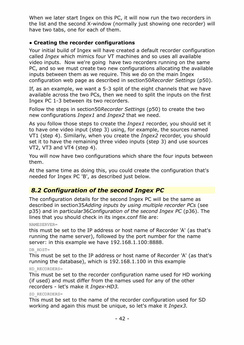
8.2 Configuration of the second Ingex PCThe configuration details for the second Ingex PC will be the same as described in section35Adding inputs by using multiple recorder PCs (see p35) and in particular36Configuration of the second Ingex PC (p36). The lines that you should check in its ingex.conf file are:NAMESERVER=this must be set to the IP address or host name of Recorder 'A' (as that's running the name server), followed by the port number for the name server: in this example we have 192.168.1.100:8888.DB_HOST=This must be set to the IP address or host name of Recorder 'A' (as that's running the database), which is 192.168.1.100 in this exampleHD_RECORDERS=This must be set to the recorder configuration name used for HD working (if used) and must differ from the names used for any of the other recorders - let's make it Ingex-HD3.SD_RECORDERS=This must be set to the name of the recorder configuration used for SD working and again this must be unique, so let's make it Ingex3.
- 42 -

Here's the relevant part of an ingex.conf file, as an example:# Ingex configuration# Copy to home directory or /etc and edit
# Path to Ingex source codeINGEX_DIR="/home/ingex/ap-workspace/ingex"
# Set the following variables to 1 to enable each facility on startup. Zero means it won't be started.CAPTURE=1MULTICAST=0TRANSFER=0INGEX_MONITOR=0SYSTEM_MONITOR=0QUAD_SPLIT=1
# CORBA naming service. Used by IngexGUI to find Recorders.NAMESERVER="192.168.1.100:8888"# CORBA dotted decimal option. Set to 1 if using dotted decimal addresses and no DNS.DOTTED_DECIMAL=1
# Database detailsDB_HOST='192.168.1.100'DB_NAME='prodautodb'DB_USER='bamzooki'DB_PASS='bamzooki'[ ... lines omitted ... ]# HD Recorders (space-separated)HD_RECORDERS="Ingex-HD3"[ ... lines omitted ... ]# SD Recorders (space-separated)SD_RECORDERS="Ingex3"[ ... remaining lines omitted ... ]
If you haven't already, you'll need to create the new recorder configuration (in this example Ingex3 and/or Ingex-HD3) using the Ingex web page, as mentioned above for Ingex1 and Ingex2 and described in section50Recorder Settings (p50). In this case all the four channels available on the second Ingex PC are assigned to this new recorder.
8.3 Configuration of the controller PCThe ingex.conf file for the controller PC can just be a copy of either of the ones we've just looked at. It's only the lineNAMESERVER=that's important, so continuing with our example this should beNAMESERVER="192.168.1.100:8888"
- 43 -

☞ Checks:
a) make sure you have the same timecode going to both Ingex PCs,
b) Start Ingex on PC 'A' and after all the windows have appeared, check that the recorder window has two tabs on it. Look in each and check that each recorder has started correctly and has registered with the name server. (Look for the text “Object Advertised” in the recorder's start-up messages.)
c) Start Ingex on PC 'B' and check that it also starts correctly and registers with the name server. (Look for the text “Object Advertised” in the recorder's start-up messages.)
d) Start a recorder controller and check that the names of all three Ingex recorders appear in the list of recorders. Select the two, e.g. Ingex2 and Ingex3, that make up the five channels, set tape IDs, etc., and see if they go into record together. Both recorders should start from the same timecode.
e) Start a second recorder controller and all three Ingex recorders will appear in its list of recorders. Select the remaining recorder, e.g. Ingex1, set the tape IDs, and see if it goes into record.
- 44 -

9 Database and Name Server on a central server
In some situations it may be an advantage to run the database and name server on a centralised server rather than on a recorder. This means that recorder PCs can be interchanged between studio areas and only a minimal change of settings on the PCs will be required. It also has the advantage that the database can be accessed as a shared facility without the Ingex PCs themselves being involved. Hence users can continue to access the web pages with their recording details and also create AAF files as they require for their editing, whether or not the Ingex recorders in the studios are running.
Clearly this configuration is more suited to a larger operation where different studios are working independently and it is convenient to transfer their recordings to a central server which is accessible from the edit suites.
This is a configuration that we have used very successfully for many of our trials of the Ingex system. However, be aware that, in this simple form, it has the disadvantage that if a failure of either the network or the shared server occurs, the recorders can no longer operate, as they can’t read their configuration data or store recording details on the server. To overcome this drawback either ensure you have a resilient network and shared server, or look at the next configuration. Also, you must not configure the transfer server to use ftp (section 4.5.1 Settings in theingex.conf file, p18) because the method of traffic control it employs in this mode will interfere with timely communication to the database.
Here's a diagram of what we want to do, with the two recorders shown in different studios.
Summary: Ingex recorders run in two separate areas whilst the name server, database and web server run on a shared server. Edit suites can
- 45 -
A larger configuration using a centralised server for the database, etc.

also access this server. Recordings are transferred from the Ingex recorders to the shared storage.
What you need to do: ensure that:
a) the name server IP details in the recorders are set to point to the central server,
b) the database details in the recorders are set to point to the central server.
If you have worked through the earlier examples, by now it will be obvious what's needed in the ingex.conf files for this setup: the name server and database lines in the ingex.conf file need to be set to the host name or IP address of the central server. Here, highlighted, are the lines of interest, and in this example the central server is at 192.168.1.10:
# Ingex configuration# Copy to home directory or /etc and edit
# Path to Ingex source codeINGEX_DIR="/home/ingex/ap-workspace/ingex"
# Set the following variables to 1 to enable each facility on startup. Zero means it won't be started.CAPTURE=1MULTICAST=0TRANSFER=1INGEX_MONITOR=0SYSTEM_MONITOR=0QUAD_SPLIT=1
# CORBA naming service. Used by IngexGUI to find Recorders.NAMESERVER="192.168.1.10:8888"# CORBA dotted decimal option. Set to 1 if using dotted decimal addresses and no DNS.DOTTED_DECIMAL=1
# Database detailsDB_HOST='192.168.1.10'DB_NAME='prodautodb'
With this arrangement you will also want the recordings to be transferred automatically to the shared storage so that they can be accessed by the Edit Suites. To do this, follow the steps described in section17Sendingrecordings to a remote file server (p17).
- 46 -

☞ Checks:
a) start the recorders and check that they manage to register with the name server (look for the text “Object Advertised” in the recorder's start-up messages).
b) Make recordings and check that the recorder doesn't produce error messages showing that it can't find its configuration from the database.
c) Go to the web page (on the central server) and check that the details of the test recordings have appeared in the list.
d) As a further test, you could check that you can access the Ingex web page and content from an edit suite.
- 47 -

10 Multiple name servers and databases
As mentioned in the previous section, the disadvantage of having the database and name server running solely on a central server is that a server or network failure would mean the Ingex recorders in the studio wouldn't be able to function.
This configuration gets around that problem by having each Ingex recorder (or cluster of recorders) in a studio running its own name server, database and web server, so each area remains fully independent. If the external network or central server goes down it doesn't matter, as the recorders will continue to operate normally.
Here's a diagram of the configuration.
The central server no longer runs a name server but it still runs a database and web server, although these are for local use only.
When the transfer process copies recordings (and router recordings) from the Ingex recorders, software running on the shared server extracts metadata from the files and updates the database on the central server. This brings the central database up-to-date with details of the recorded content (and vision mix cuts) just transferred to the central storage, so they both stay in step.
The web server running on the central server is not involved in configuring the Ingex recorders, as the web servers on the Ingex PCs are used for that. Instead it provides the facility for users to browse the central database to see details of recordings and also to create AAF files for the edit suites.
A further potential advantage of having separate nameservers running on each Ingex PC is that if these are in different studios, users in one studio
- 48 -
Using both local and remote databases to give resilience whilst allowing data to be shared between studios and edit suites

will not see the recorders for the other. This avoids the problem of a user accidentally selecting and controlling the wrong recorder!
Summary: The Ingex recorders each run in self-contained configurations. A second database and web server run on a central server which can be accessed from the edit suites. Recording and database entries are transferred automatically from the Ingex recorders.
What you need to do: ensure that:
a) the Ingex PCs operate with their own name server and database (on a per studio basis).
b) the Ingex PCs transfer their content to the central server.
c) the central server is running the daemon to update the database when new content arrives.
d) the web server on the central server uses its own database.
Here's how to set up the configuration.
10.1 Settings on the Ingex PCsSet these up as you require from the earlier configurations described in this document, with a single or multiple Ingex recorders running with a local name server and database.
10.2 Settings on the central serverConfigure the web server as described in the installation guide Building and Configuring the Ingex tapeless recording software [1] and set it to use localhost as the database host.
Install and initialise the database too, of course.
Install the two executables and the daemon to update the database automatically – described in the section Additional file server database in [1].
☞ Checks:
a) start the recorders and check that they manage to register with their own name servers (look for the text “Object Advertised” in the recorder's start-up messages).
b) Make recordings and check that the recorder doesn't produce error messages showing that it can't find its configuration from the database.
c) Go to the web page (on the central server) and check that the details of the test recordings have appeared in the list.
d) Check that you can access the Ingex web page and content from an edit suite.
- 49 -

11 Recorder Settings
Your initial build of Ingex will have created four recorders with default preset configurations. This section describes how to change those configurations or create new ones.
The primary interface for altering recorder configuration is IngexWeb. It can be viewed by opening a web browser and navigating to http://<HOST_NAME>/ingex, where <HOST_NAME> is replaced by the webserver PC in your Ingex cluster.
Most of the operational configurables can be found under the 'Setup' tab located in the upper right hand corner of the IngexWeb main page. Clicking on it will reveal nine categories, which you can see here on the left of the web page:
Each of these links is outlined in the remainder of this section.
11.1 Rec. LocationsThis section is used to manage labels for the physical locations around a studio installation, which are in turn associated with source groups. The recording location appears in the metadata of recorded MXF files and also provides a link to studio logging information, although the logging facility is not yet fully implemented.
11.2 Project NamesHere, the various Project names active on an Ingex system can be managed. Projects are the primary method of organisation for material captured by Ingex. It is up to the operator how Projects are used to manage material but generally, a Project will encompass all material relating to a series or feature. While new projects can be added from the Ingex Controller, they cannot be deleted from there. For safety, deletion of projects must be done here.
- 50 -

11.3 Series and ProgrammesHere the name of the series and the programme within that series, which the recording is part of, are set for use within the web logging tab. This facility is not yet fully implemented.
11.4 Source GroupsIngex source groups are the labels associated with the SDI video/audio streams which enter the Ingex PC. The default configuration will initialise nine source groups named Cam1 to Cam8 and Mixer Out.
Each consists of one video and 8 mono audio tracks. The Location is automatically set to Studio and Type to Live Recording. This can be seen by clicking on the name of any one of these source group definitions and the details of that definition will appear below the list of definitions as shown below:
If the user requires more than the default, this panel allows the addition, editing and removal of source groups associated with recorders on an Ingex PC. You may choose to do this so that the labelling within the Ingex web pages better reflects the physical setup of your incoming signals.
- 51 -

11.5 RecorderThis is where the recorders running on the Ingex PC are configured. There are two levels to the recorder configuration. Firstly, there's a name for an overall recorder configuration, such as Ingex, Ingex-HD or Ingex1. This name can be anything you like but it must be unique. Then for each recorder, you can have different configurations which you can switch between using the web page. This two-level naming means that you can have names for different Ingex recorders and their configurations can be changed independently between presets by using the setup web page.
When Ingex is first installed, the four default recorders will be setup: “Ingex” (Cam 1-4), “Ingex-HD”, “Ingex-Router” and “Ingex2” (Cam 5-8).
You can see the recorders listed in the screen shot here:
The recorder, “Ingex-Router”, is for configuring the “Router recorder” (outlined in section9Vision mixer cut logger on p9). This records the timing of cuts between sources as a recording is in progress and from this an edit list can be created automatically. This feature is currently under test and will be explained further once the work is complete.
Six configurations will be setup as shown in the screenshot above:
1. ’Default’ - this is a default setting which records in the same formats as the SD online configuration
2. ‘HD Quicktime DVCPRO-HD’ – this records in DVCPRO-HD only to a .mov file
3. ‘MXF HD online SD offline’ – this records an online HD VC3-185i MXF and a 20:1 Avid MJPEG offline MXF
- 52 -

4. ‘MXF SD online/offline plus browse’ – this records an online Avid 2:1 MJPEG MXF, an offline Avid 20:1 MJPEG and a MPEG4 Quicktime for browsing
5. ‘Quicktime DV50’ – this records in DV50 only to a .mov file
6. ‘Router’ – this is for the cuts information from a vision mixer
The “Ingex” configurations mimic four VT machines and so use all four available video inputs. Although the HD configurations are apparently also setup to operate as four VT recorders, your hardware is unlikely to be able to run more than two HD inputs and this limit will be applied by the HD settings already contained in the ingex.conf file.
When you need slightly different behaviour you can either edit an existing configuration or create a new one. To start with we will look at editing the default recorders
11.5.1Renaming a recorderTo rename an existing recorder, click its name and the details will appear below the ‘Recorder Configurations’. Click on the ‘Edit’ box alongside its name as shown in the screenshot below.
- 53 -

Then modify the name in the “Name” box that appears in the Edit recorder page.
Click ‘Done’ at the bottom of the page if you are finished.
At the top of the page below the name is a list of the inputs associated with the recorder. Here, the input streams created in the source group section can be allocated to the inputs of the recorder configuration. For more details of this see the next section 573 Creating a new recorder (p56).
Note: this page is also used to change a recorder's configuration preset, but this is described later in section 615 (p61)
11.5.2Renaming and editing a recorder configurationTo rename an existing configuration preset , click the name of the configuration and the details will appear below the ‘Recorder Configurations’. Click on the Edit box alongside its name in the same way
- 54 -

as for the recorder. Then modify the name in the “Name” box that appears in the ‘Edit recorder configuration page’, as seen at the top of the screenshot below. If you only want to change the name then you can click 'Done' at the bottom of the page when you've finished.
To edit the details within an existing recorder configuration preset, do the same process as when editing the configuration name to bring up the ‘Edit recorder configuration’ page. The screen shot above shows the parameters which control the behaviour of the recorder.
A recorder has up to four encoders. ENCODE1, ENCODE2 and ENCODE3 deal with taking the streams from the shared memory buffer and encoding each of them into a separate set of files. The normal configuration is to have ENCODE1 dealing with the high quality 'online' material, ENCODE2 dealing with lower quality 'offline' edit versions, and ENCODE3 not used.
QUAD is a fourth encoder which will produce a split screen video file with up to four sources, which could be taken away after a shoot by the production team for review.
The table below lists the entries and has a brief description of them. (You can find a similar description in the section Configuring Recorders in the Ingex build instructions [1].)
The parameters in the previous screen shot are as follows:
- 55 -

Parameter DescriptionENCODE1_BITC Enable encode 1 Burnt-In Timecode. This will burn in the timecode on
the files created by ENCODE1. Allowed values are true and false
ENCODE1_COPY_DEST Used by the transfer process if one is active. The directory where the
output from ENCODE1 will be copied by the transfer process. If you do not want to copy anything then set ’Transfer =0’ within the ‘ingex.conf’ file to prevent the copy service from running and delete any path set in this field.
ENCODE1_COPY_PRIORITY Used when a transfer process is running. Determines which ENCODE output files will be copied first by the transfer process. Can be any integer >=1; the lower the value, the higher the priority. If it is 1 and copying to an extra drive is enabled, material from this encoding will be copied to the extra drive (see section 4.5).
ENCODE1_DIR Directory where output from ENCODE1 will be initially saved. It is important that you ensure there is enough space available on the target drive. At the moment, the Ingex GUI will not warn the user if the destination becomes full.
ENCODE1_RESOLUTION Here, the required video encoding format can be selected. The available format can be seen by clicking on the box's drop-down menu button.
ENCODE2_* The above ENCODE1 configuration descriptions apply here too, but for the ENCODE2 process.
ENCODE3_* The above ENCODE1 configuration descriptions apply here too, but for the ENCODE3 process.
QUAD_* The above ENCODE1 configuration descriptions apply here too, but for the quad-split encode process.
IMAGE_ASPECT Sets the aspect ratio – format: LENGTH/HEIGHT, e.g. 16/9
Once you have made your required changes to these parameters, either by entering text or using the dropdown menus, remember to click the Done button. This can be seen on the lower edge of the web page in the screen shot below. The configuration should now be set up and ready to use.
REMEMBER: If you have altered a configuration that is used by the current recorder and you are currently connected to the Ingex GUI then in order for your changes to be used, you need to disconnect from and reconnect to the recorder in the Ingex GUI. This can be done by clicking on its name (highlighted in blue at the top of the screenshot below), confirm that you wish to disconnect and then reconnect by clicking on the name again. Your new altered configuration will now be used.
- 56 -

11.5.3Creating a new recorderA completely new recorder can be created by clicking 'Create New' at the top of the Recorder page, as explained in the following steps. You will need to do this if you have more than one Ingex recorder running in your setup, or if you want a convenient way of keeping different configurations for different situations.
- 57 -
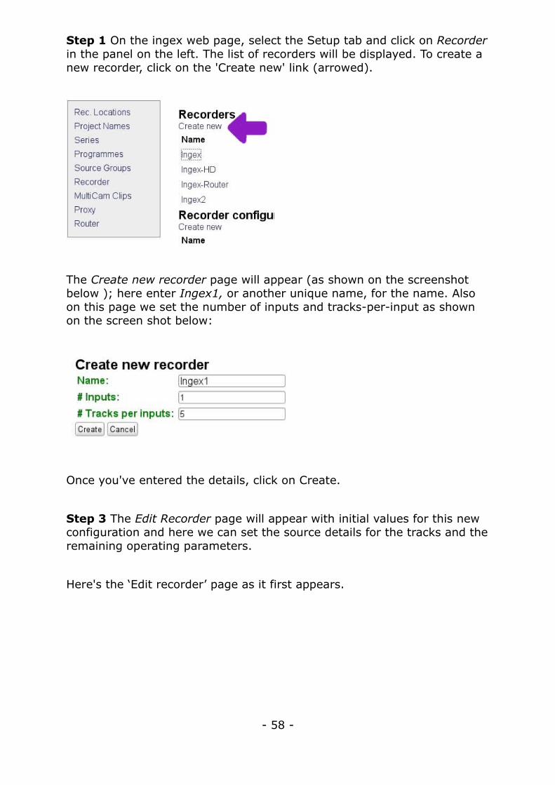
Step 1 On the ingex web page, select the Setup tab and click on Recorder in the panel on the left. The list of recorders will be displayed. To create a new recorder, click on the 'Create new' link (arrowed).
The Create new recorder page will appear (as shown on the screenshot below ); here enter Ingex1, or another unique name, for the name. Also on this page we set the number of inputs and tracks-per-input as shown on the screen shot below:
Once you've entered the details, click on Create.
Step 3 The Edit Recorder page will appear with initial values for this new configuration and here we can set the source details for the tracks and the remaining operating parameters.
Here's the ‘Edit recorder’ page as it first appears.
- 58 -

There's no need to change the Name, here Input 1, given to the input but we need to select the source for each of the tracks in the table. In this example we previously selected five tracks when we created this recorder, so we can now choose one video and up to four audio sources from the sources list for these.
Click on the drop down menu for the first track (i.e. Index 1) where it shows “not connected”. The sources available will be displayed, as shown here:
Complete the table selecting a video source for the first track and then audio sources for the remaining tracks, 2 to 5. Unwanted audio tracks can be left as “not connected”.
The column “Clip Track Number” also needs to be filled in, starting from 1 for each type of track. Looking at the completed example below shows
- 59 -

this: track 1 - the video track - has the number 1; then the audio tracks – 2 to 5 – are numbered upwards again from 1. (These numbers control the order of display of the tracks in the editor's timeline.)
(Note: you'll see that the sources available in the list are those displayed on the Sources web-page. We're not changing these in this example but you can change the name of the sources if that fits better with your set up. The names Cam1 to Cam8 fit easily with tape-based installations and thinking.)
Shown below is how a completed track list with 1 video and 4 audio inputs would look.
Step 4 This example shows only one video input used in the preset but you probably have more. In that case there will be a equivalent table for each of the other inputs. Complete these, in the same way as above, but choosing different sources from the source list. For example, Input 2 might use the Cam2 sources.
Underneath the sources is a ‘Config’ dropdown menu which sets what recorder configuration this recorder will use. You can select any of the pre-defined configurations or any custom ones which you have created.
Once you have finished, click on the ‘Done’ button. After completing the above steps, you will have a new recorder called Ingex1.
REMEMBER: If you create a new recorder, when you want to use it, its name must be entered in the ingex.conf file to ensure correct operation (see 615 below).
- 60 -
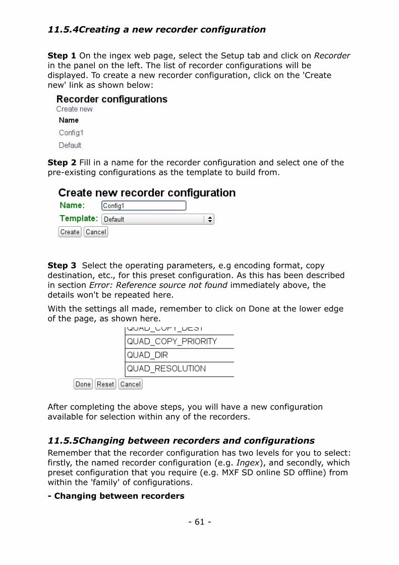
11.5.4Creating a new recorder configuration
Step 1 On the ingex web page, select the Setup tab and click on Recorder in the panel on the left. The list of recorder configurations will be displayed. To create a new recorder configuration, click on the 'Create new' link as shown below:
Step 2 Fill in a name for the recorder configuration and select one of the pre-existing configurations as the template to build from.
Step 3 Select the operating parameters, e.g encoding format, copy destination, etc., for this preset configuration. As this has been described in section Error: Reference source not found immediately above, the details won't be repeated here.
With the settings all made, remember to click on Done at the lower edge of the page, as shown here.
After completing the above steps, you will have a new configuration available for selection within any of the recorders.
11.5.5Changing between recorders and configurationsRemember that the recorder configuration has two levels for you to select: firstly, the named recorder configuration (e.g. Ingex), and secondly, which preset configuration that you require (e.g. MXF SD online SD offline) from within the 'family' of configurations.
- Changing between recorders
- 61 -

As mentioned in the configuration examples in the earlier sections, the named recorder is set in the ingex.conf file, with the SD_RECORDERS= and HD_RECORDERS= entries. The intention is that this is not changed frequently and is probably only set once for a particular situation. As a reminder, here's what you need to do:
ingex@recorder> sudo vi /etc/ingex.conf
# HD Recorders (space-separated)HD_RECORDERS="Ingex-HD"[... lines omitted ...]# SD Recorders (space-separated)SD_RECORDERS="Ingex"
- Changing between configurations
The preset configuration to be used from those created for this recorder (e.g. MXF SD online SD offline) is selected on the web page as follows.
First click on the name of the recorder (e.g. Ingex), press the Edit button alongside the Recorder name, as in the screen shot below.
Next select the required preset configuration from the ‘Config’ drop down menu that appears, as shown in the screen shot below, and click on Done to make the change.
- 62 -

When the recorder next starts recording, it will use the new configuration.
REMEMBER: If you are currently connected to the recorder whose configuration you have changed in the Ingex GUI, then in order for your changes to be used, you need to disconnect from and reconnect to the recorder in the Ingex GUI. This can be done by clicking on its name(screenshot on page 58 in section 11.5.2), confirm that you wish to disconnect and then reconnect by clicking on the name again. Your new altered configuration will now be used.
11.6 MultiCam ClipsMulticam clips can be used to group video sources that are capturing the same scene simultaneously, enabling quick synchronisation in post production. To group sources into a multicam group, click 'Create New'.
Choose the number of video 'selects' or sources to be associated with the multicam clip, as well as any audio streams that might be associated.
Currently there is no means to select which of the multicam groups that you create here will be used when you create the AAF or Apple XML file. All groups that match the content and timecode ranges defined here will be included in the file.
11.7 ProxyThe intention has been that here, the style of any proxies outputted for web viewing would be configured. It is currently unused and can be ignored.
- 63 -

11.8 RouterThe intention has been that here, the details for a vision mixer or video router would be set up for use with Ingex, allowing live cut decisions to be recorded and embedded in the AAF or Apple XML file.
Instead the settings are made elsewhere so to set up the router logger: see “Starting and Stopping the Router Logger” in the Ingex Build guide [1].
- 64 -

12 Reference
1. Building and Configuring the Ingex tapeless recording software. Available from the web page http://ingex.sf.net/studio
- 65 -