Informática y Comunicaciones Chapter 2 Application Layer Application Layer.pdf · (YouTube, Hulu,...
90
Chapter 2 Application Layer Informática y Comunicaciones Application Layer 2-1 Application Layer All material copyright 1996-2012 J.F Kurose and K.W. Ross, All Rights Reserved
Transcript of Informática y Comunicaciones Chapter 2 Application Layer Application Layer.pdf · (YouTube, Hulu,...

Chapter 2Application Layer
Informática y Comunicaciones
Application Layer 2-1
Application Layer
All material copyright 1996-2012J.F Kurose and K.W. Ross, All Rights Reserved

Chapter 2: outline
2.1 principles of network applications
2.2 Web and HTTP
2.3 FTP
2.4 electronic mail
Application Layer 2-2
2.4 electronic mail� SMTP, POP3, IMAP
2.5 DNS
2.6 P2P applications

Chapter 2: application layer
our goals:
� conceptual, implementation aspects of network application protocols
� transport-layer service models
� learn about protocols by examining popular application-level protocols� HTTP
� FTP
� SMTP / POP3 / IMAP
Application Layer 2-3
transport-layer service models
� client-server paradigm
� peer-to-peer paradigm
� SMTP / POP3 / IMAP
� DNS
� creating network applications
� socket API

Some network apps
� web
� text messaging
� remote login
� P2P file sharing
� voice over IP (e.g., Skype)
� real-time video conferencing
� social networking
� search
Application Layer 2-4
� P2P file sharing
� multi-user network games
� streaming stored video (YouTube, Hulu, Netflix)
search
� …
� …

Creating a network app
write programs that:
� run on (different) end systems
� communicate over network
� e.g., web server software communicates with browser software
applicationtransportnetworkdata linkphysical
Application Layer 2-5
no need to write software for network-core devices
� network-core devices do not run user applications
� applications on end systems allows for rapid app development, propagation
applicationtransportnetworkdata linkphysical
applicationtransportnetworkdata linkphysical

Application architectures
possible structure of applications:
� client-server
� peer-to-peer (P2P)
Application Layer 2-6

Client-server architecture
server: � always-on host
� permanent IP address
� data centers for scaling
clients:
Application Layer 2-7
clients:� communicate with server
� may be intermittently connected
� may have dynamic IP addresses
� do not communicate directly with each other
client/server

P2P architecture
� no always-on server
� arbitrary end systems directly communicate
� peers request service from other peers, provide service in return to other peers
� self scalability – new
peer-peer
Application Layer 2-8
� self scalability – new peers bring new service capacity, as well as new service demands
� peers are intermittently connected and change IP addresses
� complex management

Processes communicating
process: program running within a host
� within same host, two processes communicate using inter-process communication (defined by
client process: process that initiates communication
server process: process that waits to be contacted
clients, servers
Application Layer 2-9
communication (defined by OS)
� processes in different hosts communicate by exchanging messages
waits to be contacted
� aside: applications with P2P architectures have client processes & server processes

Sockets
� process sends/receives messages to/from its socket
� socket analogous to door
� sending process shoves message out door
� sending process relies on transport infrastructure on other side of door to deliver message to socket at receiving process
Application Layer 2-10
Internet
controlledby OS
controlled byapp developer
transport
application
physical
link
network
process
transport
application
physical
link
network
processsocket

Addressing processes
� to receive messages, process must have identifier
� host device has unique 32-bit IP address
� Q: does IP address of host on which process runs suffice for identifying the
� identifier includes both IP address and port numbersassociated with process on host.
� example port numbers:� HTTP server: 80
� mail server: 25
Application Layer 2-11
on which process runs suffice for identifying the process?
� mail server: 25
� to send HTTP message to gaia.cs.umass.edu web server:� IP address: 128.119.245.12
� port number: 80
� A: no, many processes can be running on same host

App-layer protocol defines
� types of messages exchanged,
� e.g., request, response
� message syntax:
� what fields in messages & how fields are
open protocols:
� defined in RFCs
� allows for interoperability
� e.g., HTTP, SMTP
proprietary protocols:
e.g., Skype
Application Layer 2-12
& how fields are delineated
� message semantics
� meaning of information in fields
� rules for when and how processes send & respond to messages
� e.g., Skype

What transport service does an app need?
data integrity
� some apps (e.g., file transfer, web transactions) require 100% reliable data transfer
� other apps (e.g., audio) can tolerate some loss
throughput
� some apps (e.g., multimedia) require minimum amount of throughput to be “effective”
� other apps (“elastic apps”)
Application Layer 2-13
timing
� some apps (e.g., Internet telephony, interactive games) require low delay to be “effective”
� other apps (“elastic apps”) make use of whatever throughput they get
security
� encryption, data integrity, …

Transport service requirements: common apps
application
file transfere-mail
Web documentsreal-time audio/video
data loss
no lossno lossno lossloss-tolerant
throughput
elasticelasticelasticaudio: 5kbps-1Mbps
time sensitive
nononoyes, 100’s msec
Application Layer 2-14
real-time audio/video
stored audio/videointeractive games
text messaging
loss-tolerant
loss-tolerantloss-tolerantno loss
audio: 5kbps-1Mbpsvideo:10kbps-5Mbpssame as above few kbps upelastic
yes, 100’s msec
yes, few secsyes, 100’s msecyes and no

Internet transport protocols services
TCP service:� reliable transport between sending and receiving process
� flow control: sender won’t overwhelm receiver congestion control: throttle
UDP service:� unreliable data transferbetween sending and receiving process
� does not provide:reliability, flow control,
Application Layer 2-15
overwhelm receiver � congestion control: throttle sender when network overloaded
� does not provide: timing, minimum throughput guarantee, security
� connection-oriented: setup required between client and server processes
reliability, flow control, congestion control, timing, throughput guarantee, security, orconnection setup,
Q: why bother? Why is there a UDP?

Internet apps: application, transport protocols
application
e-mailremote terminal access
Web file transfer
applicationlayer protocol
SMTP [RFC 2821]Telnet [RFC 854]HTTP [RFC 2616]FTP [RFC 959]
underlyingtransport protocol
TCPTCPTCPTCP
Application Layer 2-16
file transferstreaming multimedia
Internet telephony
FTP [RFC 959]HTTP (e.g., YouTube), RTP [RFC 1889]SIP, RTP, proprietary(e.g., Skype)
TCPTCP or UDP
TCP or UDP

Securing TCP
TCP & UDP
� no encryption
� cleartext passwds sent into socket traverse Internet in cleartext
SSL is at app layer
� Apps use SSL libraries, which “talk” to TCP
SSL socket API
� cleartext passwds sent Internet in cleartext
SSL
� provides encrypted TCP connection
� data integrity
� end-point authentication
� cleartext passwds sent into socket traverse Internet encrypted
Application Layer 2-17

Chapter 2: outline
2.1 principles of network applications� app architectures
� app requirements
2.2 Web and HTTP
Application Layer 2-18
2.2 Web and HTTP
2.3 FTP
2.4 electronic mail� SMTP, POP3, IMAP
2.5 DNS
2.6 P2P applications

Web and HTTP
First, a review…� web page consists of objects
� object can be HTML file, JPEG image, Java applet, audio file,…
� web page consists of base HTML-file which
Application Layer 2-19
� web page consists of base HTML-file which includes several referenced objects
� each object is addressable by a URL, e.g.,
www.someschool.edu/someDept/pic.gif
host name path name

HTTP overview
HTTP: hypertext transfer protocol
� Web’s application layer protocol
� client/server model� client: browser that requests, receives,
PC runningFirefox browser
Application Layer 2-20
� client: browser that requests, receives, (using HTTP protocol) and “displays” Web objects
� server: Web server sends (using HTTP protocol) objects in response to requests
server running
Apache Webserver
iphone runningSafari browser

HTTP overview (continued)
uses TCP:� client initiates TCP connection (creates socket) to server, port 80
� server accepts TCP connection from client
HTTP is “stateless”� server maintains no information about past client requests
aside
Application Layer 2-21
connection from client
� HTTP messages (application-layer protocol messages) exchanged between browser (HTTP client) and Web server (HTTP server)
� TCP connection closed
protocols that maintain “state” are complex!
� past history (state) must be maintained
� if server/client crashes, their views of “state” may be inconsistent, must be reconciled
aside

HTTP connections
non-persistent HTTP
� at most one object sent over TCP connection
� connection then
persistent HTTP
� multiple objects can be sent over single TCP connection between client, server
Application Layer 2-22
� connection then closed
� downloading multiple objects required multiple connections
between client, server

Non-persistent HTTPsuppose user enters URL:
1a. HTTP client initiates TCP connection to HTTP server (process) at www.someSchool.edu on port 80
1b. HTTP server at host www.someSchool.edu waiting for TCP connection at port 80.
(contains text, references to 10
jpeg images)www.someSchool.edu/someDepartment/home.index
Application Layer 2-23
80
2. HTTP client sends HTTP request message (containing URL) into TCP connection socket. Message indicates that client wants object someDepartment/home.index
for TCP connection at port 80. “accepts” connection, notifying client
3. HTTP server receives request message, forms response message containing requested object, and sends message into its socket
time

Non-persistent HTTP (cont.)
5. HTTP client receives response message containing html file, displays html. Parsing html file, finds 10 referenced jpeg objects
4. HTTP server closes TCP connection.
Application Layer 2-24
6. Steps 1-5 repeated for each of 10 jpeg objects
time

Non-persistent HTTP: response time
RTT (definition): time for a small packet to travel from client to server and back
HTTP response time:
� one RTT to initiate TCP connection
one RTT for HTTP request
initiate TCPconnection
RTT
request
Application Layer 2-25
� one RTT for HTTP request and first few bytes of HTTP response to return
� file transmission time
� non-persistent HTTP response time =
2RTT+ file transmission time
time to transmit file
requestfile
RTT
filereceived
time time

Persistent HTTP
non-persistent HTTP issues:� requires 2 RTTs per object
� OS overhead for each TCP connection
� browsers often open parallel TCP connections
persistent HTTP:� server leaves connection open after sending response
� subsequent HTTP messages between same
Application Layer 2-26
parallel TCP connections to fetch referenced objects
messages between same client/server sent over open connection
� client sends requests as soon as it encounters a referenced object
� as little as one RTT for all the referenced objects

HTTP request message
� two types of HTTP messages: request, response
� HTTP request message:� ASCII (human-readable format)
request line(GET, POST,
carriage return character
line-feed character
Application Layer 2-27
(GET, POST, HEAD commands)
headerlines
carriage return, line feed at startof line indicatesend of header lines
GET /index.html HTTP/1.1\r\nHost: www-net.cs.umass.edu\r\nUser-Agent: Firefox/3.6.10\r\nAccept: text/html,application/xhtml+xml\r\nAccept-Language: en-us,en;q=0.5\r\nAccept-Encoding: gzip,deflate\r\nAccept-Charset: ISO-8859-1,utf-8;q=0.7\r\nKeep-Alive: 115\r\nConnection: keep-alive\r\n\r\n

HTTP request message: general format
requestline
headerlines
method sp sp cr lfversionURL
cr lfvalueheader field name
~~ ~~
Application Layer 2-28
body
cr lfvalueheader field name
cr lf
entity body~~ ~~

Uploading form input
POST method:� web page often includes form input
� input is uploaded to server in entity body
URL method:
Application Layer 2-29
URL method:� uses GET method
� input is uploaded in URL field of request line:
www.somesite.com/animalsearch?monkeys&banana

Method types
HTTP/1.0:� GET
� POST
� HEAD
� asks server to leave
HTTP/1.1:� GET, POST, HEAD
� PUT
� uploads file in entity body to path specified
Application Layer 2-30
� asks server to leave requested object out of response
body to path specified in URL field
� DELETE
� deletes file specified in the URL field

HTTP response message
status line(protocolstatus codestatus phrase)
header
HTTP/1.1 200 OK\r\nDate: Sun, 26 Sep 2010 20:09:20 GMT\r\nServer: Apache/2.0.52 (CentOS)\r\nLast-Modified: Tue, 30 Oct 2007 17:00:02
GMT\r\nETag: "17dc6-a5c-bf716880"\r\n
Application Layer 2-31
headerlines
data, e.g., requestedHTML file
ETag: "17dc6-a5c-bf716880"\r\nAccept-Ranges: bytes\r\nContent-Length: 2652\r\nKeep-Alive: timeout=10, max=100\r\nConnection: Keep-Alive\r\nContent-Type: text/html; charset=ISO-8859-
1\r\n\r\ndata data data data data ...

HTTP response status codes
200 OK� request succeeded, requested object later in this msg
301 Moved Permanently
� status code appears in 1st line in server-to-client response message.
� some sample codes:
Application Layer 2-32
301 Moved Permanently� requested object moved, new location specified later in this msg (Location:)
400 Bad Request� request msg not understood by server
404 Not Found� requested document not found on this server
505 HTTP Version Not Supported

User-server state: cookies
many Web sites use cookies
four components:
1) cookie header line of HTTP responsemessage
example:
� Susan always access Internet from PC
� visits specific e-commerce site for first time
� when initial HTTP requests
Application Layer 2-33
message
2) cookie header line in next HTTP requestmessage
3) cookie file kept on user’s host, managed by user’s browser
4) back-end database at Web site
� when initial HTTP requests arrives at site, site creates:
� unique ID
� entry in backend database for ID

Cookies: keeping “state” (cont.)
client server
cookie file
ebay 8734usual http request msg Amazon server
creates ID1678 for user create
entry
usual http response set-cookie: 1678
ebay 8734amazon 1678
backenddatabase
Application Layer 2-34
usual http response msg
usual http response msg
one week later:
usual http request msgcookie: 1678 cookie-
specificaction
access
amazon 1678
usual http request msgcookie: 1678 cookie-
specificaction
access
ebay 8734amazon 1678

Cookies (continued)
what cookies can be used for:
� authorization� shopping carts� recommendations� user session state (Web e-mail)
cookies and privacy:
� cookies permit sites to learn a lot about you
� you may supply name and e-mail to sites
aside
Application Layer 2-35
� user session state (Web e-mail)
how to keep “state”:� protocol endpoints: maintain state at sender/receiver over multiple transactions
� cookies: http messages carry state

Web caches (proxy server)
� user sets browser: Web accesses via cache
� browser sends all HTTP requests to cache
� object in cache: cache
goal: satisfy client request without involving origin server
proxyserver
Application Layer 2-36
� object in cache: cache returns object
� else cache requests object from origin server, then returns object to client
client
client origin server
origin server

More about Web caching
� cache acts as both client and server� server for original requesting client
� client to origin server
typically cache is
why Web caching?
� reduce response time for client request
� reduce traffic on an institution’s access link
Application Layer 2-37
� typically cache is installed by ISP (university, company, residential ISP)
institution’s access link� Internet dense with caches: enables “poor”content providers to effectively deliver content (so too does P2P file sharing)

Caching example:
originservers
publicInternet
assumptions:� avg object size: 1Mb
� avg request rate from browsers to origin servers:15 req/sec
� avg data rate to browsers: 15 Mbps
� RTT from institutional router to any origin server: 2 sec
Application Layer 2-38
institutionalnetwork
100 Mbps LAN
15 Mbps access link
origin server: 2 sec
� access link rate: 15 Mbps
consequences:� LAN utilization: 15%
� access link utilization = 100%
� total delay = Internet delay + access delay + LAN delay
= 2 sec + minutes + usecs
problem!

assumptions:� avg object size: 1Mb
� avg request rate from browsers to origin servers:15 req/sec
� avg data rate to browsers: 15 Mbps
� RTT from institutional router to any origin server: 2 sec
Caching example: fatter access link
originservers
publicInternet
Application Layer 2-39
origin server: 2 sec
� access link rate: 15 Mbps
consequences:� LAN utilization: 15%
� access link utilization = 100%
� total delay = Internet delay + access delay + LAN delay
= 2 sec + minutes + usecs
15 Mbps access link
75 Mbps 75 Mbps
msecs
Cost: increased access link speed (not cheap!)
20%
institutionalnetwork
100 Mbps LAN

Caching example: install local cache
originservers
assumptions:� avg object size: 1Mb
� avg request rate from browsers to origin servers:15 req/sec
� avg data rate to browsers: 15 Mbps
� RTT from institutional router to any origin server: 2 sec
publicInternet
institutionalnetwork
100 Mbps LAN
Application Layer 2-40
15 Mbps access link
local web cache
origin server: 2 sec
� access link rate: 15 Mbps
consequences:� LAN utilization: 15%
� access link utilization = 100%
� total delay = Internet delay + access delay + LAN delay
= 2 sec + minutes + usecs
??
How to compute link utilization, delay?
Cost: web cache (cheap!)

Caching example: install local cache
Calculating access link utilization, delay with cache:
� suppose cache hit rate is 0.4� 40% requests satisfied at cache, 60% requests satisfied at origin
originservers
� access link utilization: 60% of requests use access link
publicInternet
Application Layer 2-41
15 Mbps access link
� 60% of requests use access link
� data rate to browsers over access link = 0.6*15 Mbps = 9 Mbps � utilization = 9/15 = 0.6
� total delay� = 0.6 * (delay from origin servers) +0.4 * (delay when satisfied at cache)
� = 0.6 (2 secs) + 0.4 (~msecs) � = ~ 1.2 secs� less than with 75 Mbps link (and cheaper too!)
institutionalnetwork
100 Mbps LAN
local web cache

Conditional GET
� Goal: don’t send object if cache has up-to-date cached version� no object transmission delay
� lower link utilization
� cache: specify date of
HTTP request msgIf-modified-since: <date>
HTTP responseHTTP/1.0
object not
modifiedbefore<date>
client server
Application Layer 2-42
� cache: specify date of cached copy in HTTP requestIf-modified-since: <date>
� server: response contains no object if cached copy is up-to-date: HTTP/1.0 304 Not Modified
304 Not Modified <date>
HTTP request msgIf-modified-since: <date>
HTTP responseHTTP/1.0 200 OK
<data>
object modified
after <date>

Chapter 2: outline
2.1 principles of network applications� app architectures
� app requirements
2.2 Web and HTTP
Application Layer 2-43
2.2 Web and HTTP
2.3 FTP
2.4 electronic mail� SMTP, POP3, IMAP
2.5 DNS
2.6 P2P applications

FTP: the file transfer protocol
file transferFTP
server
FTPuser
interface
FTPclient
local filesystem
remote filesystem
user at host
Application Layer 2-44
� transfer file to/from remote host� client/server model
� client: side that initiates transfer (either to/from remote)
� server: remote host
� ftp: RFC 959� ftp server: port 21

FTP: separate control, data connections
� FTP client contacts FTP server at port 21, using TCP
� client authorized over control connection
� client browses remote directory, sends commands
FTPclient
FTPserver
TCP control connection,server port 21
TCP data connection,server port 20
Application Layer 2-45
directory, sends commands over control connection
� when server receives file transfer command, serveropens 2nd TCP data connection (for file) to client
� after transferring one file, server closes data connection
� server opens another TCP data connection to transfer another file
� control connection: “out of band”
� FTP server maintains “state”: current directory, earlier authentication

FTP commands, responses
sample commands:� sent as ASCII text over control channel
� USER username� PASS password
� LIST return list of file in
sample return codes� status code and phrase (as in HTTP)
� 331 Username OK, password required
� 125 data
Application Layer 2-46
� LIST return list of file in current directory
� RETR filenameretrieves (gets) file
� STOR filename stores (puts) file onto remote host
� 125 data connection already open; transfer starting
� 425 Can’t open data connection
� 452 Error writing file

Chapter 2: outline
2.1 principles of network applications� app architectures
� app requirements
2.2 Web and HTTP
Application Layer 2-47
2.2 Web and HTTP
2.3 FTP
2.4 electronic mail� SMTP, POP3, IMAP
2.5 DNS
2.6 P2P applications

Electronic mail
Three major components:� user agents
� mail servers
� simple mail transfer protocol: SMTP
user mailbox
outgoing message queue
mailserver
mailserver
SMTP
useragent
useragent
useragent
Application Layer 2-48
User Agent� a.k.a. “mail reader”� composing, editing, reading mail messages
� e.g., Outlook, Thunderbird, iPhone mail client
� outgoing, incoming messages stored on server
server
mailserver
SMTP
SMTPagent
useragent
useragent
useragent

Electronic mail: mail servers
mail servers:� mailbox contains incoming messages for user
� message queue of outgoing (to be sent) mail messages
� SMTP protocol between mail
server
mailserver
SMTP
useragent
useragent
useragent
Application Layer 2-49
� SMTP protocol between mail servers to send email messages
� client: sending mail server
� “server”: receiving mail server
server
mailserver
SMTP
SMTPagent
useragent
useragent
useragent

Electronic Mail: SMTP [RFC 2821]
� uses TCP to reliably transfer email message from client to server, port 25
� direct transfer: sending server to receiving server
� three phases of transfer
Application Layer 2-50
three phases of transfer� handshaking (greeting)
� transfer of messages
� closure
� command/response interaction (like HTTP, FTP)� commands: ASCII text
� response: status code and phrase
� messages must be in 7-bit ASCI

Scenario: Alice sends message to Bob
1) Alice uses UA to compose message “to”[email protected]
2) Alice’s UA sends message to her mail server; message placed in message queue
3) client side of SMTP opens
4) SMTP client sends Alice’s message over the TCP connection
5) Bob’s mail server places the message in Bob’s mailbox
6) Bob invokes his user agent to read message
Application Layer 2-51
useragent
3) client side of SMTP opens TCP connection with Bob’s mail server
to read message
mailserver
mailserver
1
2 3 4
5
6
Alice’s mail server Bob’s mail server
useragent

SMTP: final words
� SMTP uses persistent connections
� SMTP requires message (header & body) to be in 7-bit ASCII
� SMTP server uses
comparison with HTTP:
� HTTP: pull
� SMTP: push
� both have ASCII command/response
Application Layer 2-52
� SMTP server uses CRLF.CRLF to determine end of message
command/response interaction, status codes
� HTTP: each object encapsulated in its own response msg
� SMTP: multiple objects sent in multipart msg

Mail message format
SMTP: protocol for exchanging email msgs
RFC 822: standard for text message format:
� header lines, e.g.,� To:
header
body
blankline
Application Layer 2-53
� To:
� From:
� Subject:
different from SMTP MAIL FROM, RCPT TO:commands!
� Body: the “message”� ASCII characters only
body

Mail access protocols
� SMTP: delivery/storage to receiver’s server
sender’s mail server
SMTP SMTPmail access
protocol
receiver’s mail server
(e.g., POP, IMAP)
useragent
useragent
Application Layer 2-54
� SMTP: delivery/storage to receiver’s server� mail access protocol: retrieval from server
� POP: Post Office Protocol [RFC 1939]: authorization, download
� IMAP: Internet Mail Access Protocol [RFC 1730]: more features, including manipulation of stored msgs on server
� HTTP: gmail, Hotmail, Yahoo! Mail, etc.

POP3 (more) and IMAP
more about POP3� previous example uses POP3 “download and delete” mode� Bob cannot re-read e-mail if he changes client
IMAP� keeps all messages in one place: at server
� allows user to organize messages in folders
� keeps user state across
Application Layer 2-55
mail if he changes client
� POP3 “download-and-keep”: copies of messages on different clients
� POP3 is stateless across sessions
� keeps user state across sessions:
� names of folders and mappings between message IDs and folder name

Chapter 2: outline
2.1 principles of network applications� app architectures
� app requirements
2.2 Web and HTTP
Application Layer 2-56
2.2 Web and HTTP
2.3 FTP
2.4 electronic mail� SMTP, POP3, IMAP
2.5 DNS
2.6 P2P applications

DNS: domain name system
people: many identifiers:
� SSN, name, passport #
Internet hosts, routers:
� IP address (32 bit) -used for addressing datagrams
Domain Name System:� distributed databaseimplemented in hierarchy of many name servers
� application-layer protocol: hosts, name servers communicate to
Application Layer 2-57
datagrams
� “name”, e.g., www.yahoo.com -used by humans
Q: how to map between IP address and name, and vice versa ?
name servers communicate to resolve names (address/name translation)
� note: core Internet function, implemented as application-layer protocol
� complexity at network’s “edge”

DNS: services, structure
why not centralize DNS?� single point of failure
� traffic volume
� distant centralized database
� maintenance
DNS services� hostname to IP address translation
� host aliasing� canonical, alias names
� mail server aliasing
Application Layer 2-58
� mail server aliasing
� load distribution
� replicated Web servers: many IP addresses correspond to one name
A: doesn’t scale!

Root DNS Servers
com DNS servers org DNS servers edu DNS servers
poly.eduDNS servers
umass.eduDNS servers
yahoo.comDNS servers
amazon.comDNS servers
pbs.orgDNS servers
DNS: a distributed, hierarchical database
… …
Application Layer 2-59
DNS servers DNS servers DNS servers
client wants IP for www.amazon.com; 1st approx:� client queries root server to find com DNS server
� client queries .com DNS server to get amazon.com DNS server
� client queries amazon.com DNS server to get IP address for www.amazon.com

DNS: root name servers
� contacted by local name server that cannot resolve name
� root name server:� contacts authoritative name server if name mapping not known
� gets mapping
� returns mapping to local name server
Application Layer 2-60
13 root name “servers”worldwide
a. Verisign, Los Angeles CA(5 other sites)
b. USC-ISI Marina del Rey, CAl. ICANN Los Angeles, CA
(41 other sites)
e. NASA Mt View, CAf. Internet Software C.Palo Alto, CA (and 48 other sites)
i. Netnod, Stockholm (37 other sites)
k. RIPE London (17 other sites)
m. WIDE Tokyo(5 other sites)
c. Cogent, Herndon, VA (5 other sites)d. U Maryland College Park, MDh. ARL Aberdeen, MDj. Verisign, Dulles VA (69 other sites )
g. US DoD Columbus, OH (5 other sites)

TLD, authoritative servers
top-level domain (TLD) servers:� responsible for com, org, net, edu, aero, jobs, museums, and all top-level country domains, e.g.: uk, fr, ca, jp
� Network Solutions maintains servers for .com TLD
� Educause for .edu TLD
Application Layer 2-61
� Educause for .edu TLD
authoritative DNS servers:� organization’s own DNS server(s), providing authoritative hostname to IP mappings for organization’s named hosts
� can be maintained by organization or service provider

Local DNS name server
� does not strictly belong to hierarchy
� each ISP (residential ISP, company, university) has one� also called “default name server”
� when host makes DNS query, query is sent to its
Application Layer 2-62
� when host makes DNS query, query is sent to its local DNS server� has local cache of recent name-to-address translation pairs (but may be out of date!)
� acts as proxy, forwards query into hierarchy

root DNS server
local DNS serverdns.poly.edu
23
4
5
TLD DNS server
DNS name resolution example
� host at cis.poly.edu wants IP address for gaia.cs.umass.edu
iterated query:
Application Layer 2-63
requesting hostcis.poly.edu
gaia.cs.umass.edu
dns.poly.edu
16
authoritative DNS serverdns.cs.umass.edu
78
iterated query:� contacted server replies with name of server to contact
� “I don’t know this name, but ask this server”

45
6
3
recursive query:� puts burden of name resolution on contacted name server
root DNS server
local DNS serverdns.poly.edu
27
DNS name resolution example
TLD DNS server
Application Layer 2-64
45server
� heavy load at upper levels of hierarchy?
requesting hostcis.poly.edu
gaia.cs.umass.edu
dns.poly.edu
1
authoritative DNS serverdns.cs.umass.edu
8

DNS: caching, updating records
� once (any) name server learns mapping, it cachesmapping� cache entries timeout (disappear) after some time (TTL)
� TLD servers typically cached in local name servers
• thus root name servers not often visited
cached entries may be out-of-date (best effort
Application Layer 2-65
� cached entries may be out-of-date (best effort name-to-address translation!)� if name host changes IP address, may not be known Internet-wide until all TTLs expire
� update/notify mechanisms proposed IETF standard� RFC 2136

DNS records
DNS: distributed db storing resource records (RR)
RR format: (name, value, type, ttl)
type=A� name is hostname
type=CNAME� name is alias name for some
Application Layer 2-66
type=NS� name is domain (e.g., foo.com)
� value is hostname of authoritative name server for this domain
� name is hostname
� value is IP address� name is alias name for some
“canonical” (the real) name� www.ibm.com is really
servereast.backup2.ibm.com
� value is canonical name
type=MX� value is name of mailserver associated with name
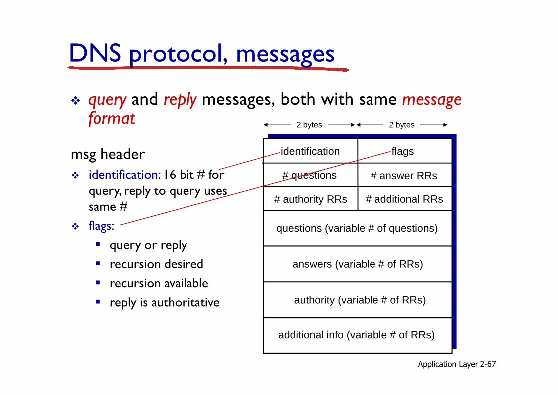
DNS protocol, messages
� query and reply messages, both with same message format
msg header
� identification: 16 bit # for query, reply to query uses
identification flags
# questions
# additional RRs# authority RRs
# answer RRs
2 bytes 2 bytes
Application Layer 2-67
query, reply to query uses same #
� flags:
� query or reply
� recursion desired
� recursion available
� reply is authoritative
questions (variable # of questions)
# additional RRs# authority RRs
answers (variable # of RRs)
authority (variable # of RRs)
additional info (variable # of RRs)

identification flags
# questions
# additional RRs# authority RRs
# answer RRs
DNS protocol, messages
2 bytes 2 bytes
Application Layer 2-68
name, type fieldsfor a query
RRs in responseto query
records forauthoritative servers
additional “helpful”info that may be used
questions (variable # of questions)
# additional RRs# authority RRs
answers (variable # of RRs)
authority (variable # of RRs)
additional info (variable # of RRs)

Inserting records into DNS
� example: new startup “Network Utopia”� register name networkuptopia.com at DNS registrar(e.g., Network Solutions)� provide names, IP addresses of authoritative name server (primary and secondary)
� registrar inserts two RRs into .com TLD server:
Application Layer 2-69
� registrar inserts two RRs into .com TLD server:(networkutopia.com, dns1.networkutopia.com, NS)(dns1.networkutopia.com, 212.212.212.1, A)
� create authoritative server type A record for www.networkuptopia.com; type MX record for networkutopia.com

Attacking DNS
DDoS attacks
� Bombard root servers with traffic� Not successful to date
� Traffic Filtering
Redirect attacks
� Man-in-middle� Intercept queries
� DNS poisoning� Send bogus relies to � Traffic Filtering
� Local DNS servers cache IPs of TLD servers, allowing root server bypass
� Bombard TLD servers� Potentially more dangerous
� Send bogus relies to DNS server, which caches
Exploit DNS for DDoS
� Send queries with spoofed source address: target IP
� Requires amplificationApplication Layer 2-70

Chapter 2: outline
2.1 principles of network applications� app architectures
� app requirements
2.2 Web and HTTP
Application Layer 2-71
2.2 Web and HTTP
2.3 FTP
2.4 electronic mail� SMTP, POP3, IMAP
2.5 DNS
2.6 P2P applications

Pure P2P architecture
� no always-on server
� arbitrary end systems directly communicate
� peers are intermittently connected and change IP addresses
Application Layer 2-72
examples:� file distribution (BitTorrent)
� Streaming (KanKan)
� VoIP (Skype)
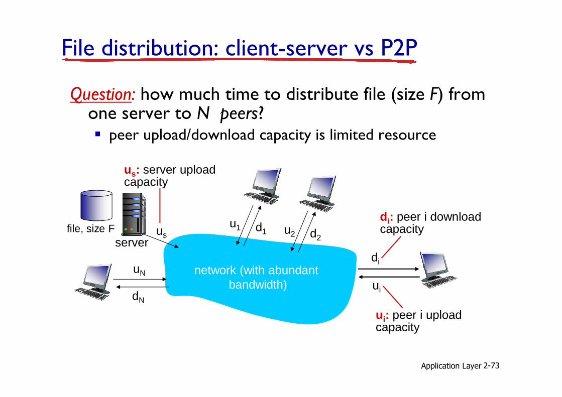
File distribution: client-server vs P2P
Question: how much time to distribute file (size F) from one server to N peers?� peer upload/download capacity is limited resource
us: server upload capacity
Application Layer 2-73
us
uN
dN
server
network (with abundantbandwidth)
file, size F
ui: peer i upload capacity
di: peer i download capacityu2 d2
u1 d1
di
ui

File distribution time: client-server
� server transmission: mustsequentially send (upload) N file copies:� time to send one copy: F/us
� time to send N copies: NF/us
� client: each client must download file copy
us
network
di
ui
F
Application Layer 2-74
increases linearly in N
time to distribute F to N clients using
client-server approachDc-s > max{NF/us,,F/dmin}
client: each client must download file copy� dmin = min client download rate
� min client download time: F/dmin

File distribution time: P2P
� server transmission: mustupload at least one copy
� time to send one copy: F/us
us
network
di
ui
F
� client: each client must download file copy� min client download time: F/dmin
clients: as aggregate must download NF bits
Application Layer 2-75
time to distribute F to N clients using
P2P approachDP2P > max{F/us,,F/dmin,,NF/(us + Σui)}
� clients: as aggregate must download NF bits
� max upload rate (limting max download rate) is us + Σui
… but so does this, as each peer brings service capacityincreases linearly in N …

2.5
3
3.5M
inim
um D
istr
ibut
ion
Tim
e P2P
Client-Server
Client-server vs. P2P: example
client upload rate = u, F/u = 1 hour, us = 10u, dmin ≥ us
Application Layer 2-76
0
0.5
1
1.5
2
0 5 10 15 20 25 30 35
N
Min
imum
Dis
trib
utio
n T
ime

P2P file distribution: BitTorrent
tracker: tracks peers participating in torrent
torrent: group of peers exchanging chunks of a file
� file divided into 256Kb chunks� peers in torrent send/receive file chunks
Application Layer 2-77
Alice arrives …… obtains listof peers from tracker… and begins exchanging file chunks with peers in torrent

� peer joining torrent:
� has no chunks, but will accumulate them over time from other peers
� registers with tracker to get list of peers, connects to
P2P file distribution: BitTorrent
Application Layer 2-78
list of peers, connects to subset of peers (“neighbors”)
� while downloading, peer uploads chunks to other peers
� peer may change peers with whom it exchanges chunks
� churn: peers may come and go
� once peer has entire file, it may (selfishly) leave or (altruistically) remain in torrent

BitTorrent: requesting, sending file chunks
requesting chunks:� at any given time, different peers have different subsets of file chunks
� periodically, Alice asks each peer for list of chunks that
sending chunks: tit-for-tat� Alice sends chunks to those four peers currently sending her chunks at highest rate� other peers are choked by Alice (do not receive chunks from her)
Application Layer 2-79
peer for list of chunks that they have
� Alice requests missing chunks from peers, rarest first
(do not receive chunks from her)
� re-evaluate top 4 every10 secs
� every 30 secs: randomly select another peer, starts sending chunks� “optimistically unchoke” this peer� newly chosen peer may join top 4

BitTorrent: tit-for-tat
(1) Alice “optimistically unchokes” Bob(2) Alice becomes one of Bob’s top-four providers; Bob reciprocates(3) Bob becomes one of Alice’s top-four providers
Application Layer 2-80
higher upload rate: find better trading partners, get file faster !

D i s t r i b u t e d H a s h T a b l e ( D H T )
�DHT: a distributed P2P database
� database has (key, value) pairs; examples:
� key: ss number; value: human name
� key: movie title; value: IP address� key: movie title; value: IP address
�Distribute the (key, value) pairs over the (millions of peers)
� a peer queries DHT with key
� DHT returns values that match the key
� peers can also insert (key, value) pairsApplication Layer 2-81

Q: how to assign keys to peers?
� central issue:
� assigning (key, value) pairs to peers.
� basic idea:
� convert each key to an integerconvert each key to an integer
� Assign integer to each peer
� put (key,value) pair in the peer that is closestto the key
Application Layer 2-82

DHT identifiers
� assign integer identifier to each peer in range [0,2n-1] for some n.
� each identifier represented by n bits.
� require each key to be an integer in same range
� to get integer key, hash original key
� e.g., key = hash(“Led Zeppelin IV”)� this is why its is referred to as a distributed “hash”
table
Application Layer 2-83

Assign keys to peers
� rule: assign key to the peer that has the closest ID.
� convention in lecture: closest is the immediate successor of the key.
� e.g., n=4; peers: 1,3,4,5,8,10,12,14;
� key = 13, then successor peer = 14
� key = 15, then successor peer = 1
Application Layer 2-84

1
3
4
15
Circular DHT (1)
5
810
12
� each peer only aware of immediate successor and predecessor.
� “overlay network”Application Layer 2-85

0001
0011
1111
Who’s responsiblefor key 1110 ?
I am
O(N) messages
on avgerage to resolve
query, when there
are N peers
Circular DHT (1)
0100
0101
10001010
1100
1110
1110
1110
1110
1110
1110
Define closestas closestsuccessor
Application Layer 2-86

Circular DHT with shortcuts1
3
4
512
15
Who’s responsible for key 1110?
� each peer keeps track of IP addresses of predecessor, successor, short cuts.
� reduced from 6 to 2 messages.� possible to design shortcuts so O(log N) neighbors, O(log N) messages in query
5
810
12
Application Layer 2-87

Peer churn1
3
4
512
15
handling peer churn:�peers may come and go (churn)
�each peer knows address of its two successors
�each peer periodically pings its two successors to check aliveness
�if immediate successor leaves, choose next successor as new
example: peer 5 abruptly leaves
�peer 4 detects peer 5 departure; makes 8 its immediate successor; asks 8 who its immediate successor is; makes 8’s immediate successor its second successor.
�what if peer 13 wants to join?
5
810
12choose next successor as new immediate successor
Application Layer 2-88

Chapter 2: summary
� application architectures
� client-server
� P2P
� application service requirements:
our study of network apps now complete!
� specific protocols:
� HTTP
� FTP
� SMTP, POP, IMAP
Application Layer 2-89
requirements:
� reliability, bandwidth, delay
� Internet transport service model
� connection-oriented, reliable: TCP
� unreliable, datagrams: UDP
� SMTP, POP, IMAP
� DNS
� P2P: BitTorrent, DHT

� typical request/reply message exchange:
� client requests info or service
� server responds with
important themes:
� control vs. data msgs
� in-band, out-of-band
centralized vs. decentralized
Chapter 2: summary
most importantly: learned about protocols!
Application Layer 2-90
� server responds with data, status code
� message formats:
� headers: fields giving info about data
� data: info being communicated
� centralized vs. decentralized
� stateless vs. stateful
� reliable vs. unreliable msg transfer
� “complexity at network edge”