INFORMATION TO USERS The most advanced...
207
A parametric study on the behavior of slender reinforced concrete frames Item Type text; Thesis-Reproduction (electronic) Authors Lanzas, Lourdes Eneida, 1962- Publisher The University of Arizona. Rights Copyright © is held by the author. Digital access to this material is made possible by the University Libraries, University of Arizona. Further transmission, reproduction or presentation (such as public display or performance) of protected items is prohibited except with permission of the author. Download date 13/07/2018 04:51:21 Link to Item http://hdl.handle.net/10150/276945
Transcript of INFORMATION TO USERS The most advanced...

A parametric study on the behavior ofslender reinforced concrete frames
Item Type text; Thesis-Reproduction (electronic)
Authors Lanzas, Lourdes Eneida, 1962-
Publisher The University of Arizona.
Rights Copyright © is held by the author. Digital access to this materialis made possible by the University Libraries, University of Arizona.Further transmission, reproduction or presentation (such aspublic display or performance) of protected items is prohibitedexcept with permission of the author.
Download date 13/07/2018 04:51:21
Link to Item http://hdl.handle.net/10150/276945

INFORMATION TO USERS
The most advanced technology has been used to photograph and reproduce this manuscript from the microfilm master. UMI films the text directly from the original or copy submitted. Thus, some thesis and dissertation copies are in typewriter face, while others may be from any type of computer printer.
The quality of this reproduction is dependent upon the quality of the copy submitted. Broken or indistinct print, colored or poor quality illustrations and photographs, print bleedthrough, substandard margins, and improper alignment can adversely affect reproduction.
In the unlikely event that the author did not send UMI a complete manuscript and there are missing pages, these will be noted. Also, if unauthorized copyright material had to be removed, a note will indicate the deletion.
Oversize materials (e.g., maps, drawings, charts) are reproduced by sectioning the original, beginning at the upper left-hand corner and continuing from left to right in equal sections with small overlaps. Each original is also photographed in one exposure and is included in reduced form at the back of the book. These are also available as one exposure on a standard 35mm slide or as a 17" x 23" black and white photographic print for an additional charge.
Photographs included in the original manuscript have been reproduced xerographically in this copy. Higher quality 6" x 9" black and white photographic prints are available for any photographs or illustrations appearing in this copy for an additional charge. Contact UMI directly to order.
University Microfilms International A Bell & Howell information Company
300 North Zeeb Road, Ann Arbor, Ml 48106-1346 USA 313/761-4700 800/521-0600

Mtt..,,. --
Order Number 1336347
A parametric study on the behavior of slender reinforced concrete frames
Lanzas, Lourdes Eneida, M.S.
The University of Arizona, 1989
U M I 300 N. Zeeb Rd. Ann Arbor, MI 48106


A PARAMETRIC STUDY ON THE
BEHAVIOR OF SLENDER REINFORCED CONCRETE FRAMES
by
Lourdes Eneida Lanzas
A Thesis Submitted to the Faculty of the
DEPARTMENT OF CIVIL ENGINEERING & ENGINEERING MECHANICS
In Partial Fulfillment of the Requirements For the Degree of
MASTER OF SCIENCE WITH A MAJOR IN CIVIL ENGINEERING
In the Graduate College
THE UNIVERSITY OF ARIZONA
19 8 9

2
STATEMENT BY AUTHOR
This thesis has been submitted in partial fulfillment of requirements for an
advanced degree at The University of Arizona and is deposited in the University
Library to be made available to borrowers under rules of the Library.
Brief quotations from this thesis are allowable without special permission, pro
vided that accurate acknowledgement of source is made. Requests for permission
for extended quotation from or reproduction of this manuscript in whole or in part
may be granted by the head of the major department or the Dean of the Graduate
College when in his or her judgment the proposed use of the material is in the in
terests of scholarship. In all other instances, however, permission must be obtained
from the author.
SIGNED:
APPROVAL BY THESIS DIRECTOR
This thesis has been approved on the date shown below:
Dr. M. R. Ehsani Associate Professor of Civil Engineering
and Engineering Mechanics
Date
3
ACKNOWLEDGMENT
The author would like to thank Dr. M. R. Ehsani for his help, guidance, and
encouragement in the development of this thesis. The author is also grateful to Dr.
R. M. Richard and Dr. A. Haldar for their time devoted in reviewing this paper
and for their willingness to serve on my committee.
The author wishes to acknowledge her parents and other family members
for their encouragement and faith. Special thanks is due to the author's husband,
Larry, for his moral support, understanding, and assistance in the preparation of
this manuscript.

TABLE OF CONTENTS
page
LIST OF FIGURES 6
LIST OF TABLES 7
ABSTRACT 12
CHAPTER 1 - INTRODUCTION 13
CHAPTER 2 - LITERATURE REVIEW 15
2.1 General 15
2.2 Moment Magnifier Method IS
2.3 Review of Recent Investigations 21
CHAPTER 3 - COMPUTER PROGRAM FPIER 37
CHAPTER 4 - PARAMETRIC STUDY 41
CHAPTER 5 - ANALYSIS OF RESULTS 53
5.1 Symmetrical Vertical Loading Pattern 54
5.1.1 Analysis according to the axial load intensity, P/P0 54
5.1.2 Analysis according to the percentage of steel, p 55
5.1.3 Analysis according to the slenderness ratio, klu/r 61
5.1.4 Analysis according to the shape of column cross section ... 66
5.1.5 Analysis according to flexural stiffness ratio 66
5.2 Unsymmetrical Vertical Loading Pattern 73
5.2.1 Analysis according to the axial load intensity, P/P0 73
5.2.2 Analysis according to the percentage of steel, p 85

TABLE OF CONTENTS-Continued
page
5.2.3 Analysis according to the slenderness ratio, klu/r 85
5.2.4 Analysis according to the shape of column cross section ... 91
5.2.5 Analysis according to flexural stiffness ratio 91
CHAPTER 6 - SUMMARY AND CONCLUSIONS 105
APPENDIX A 107
APPENDIX B 149
REFERENCES 201
6
LIST OF FIGURES
Figure page
2.1 Mechanism Curve Method 23
2.2 Fiber model representation of a rectangular solid prismatic column 27
2.3 Tangent stiffness of a fiber 29
2.4 Stress-strain characteristic of steel (fy = 40ksi ) taking into account the correction in steel strain 31
2.5 Hognestad stress-strain curve 32
2.6 Compressive stress-strain curve of confined concrete from Ford 33
3.1 Cross section shapes and reinforcement position 38
4.1 Frame configuration used in the analysis 42
4.2 Number of segments used 46
4.3 Comparison of the ACI Moment Magnifier Method predictions with measured moments at the four corners of frame R5L3PP0.3 for various horizontal loads 48
4.4 Comparison of the ACI Moment Magnifier Method predictions with measured moments at the four corners of frame C5H3P0.2 for various horizontal loads 49
4.5 Comparison of the ACI Moment Magnifier Method predictions with measured moments at the four corners of frame C3L5PP0.5 for various horizontal loads 50

7
LIST OF TABLES
Table page
4.1 Beam and columns cross section dimensions 45
5.1 ACI/Analysis ratios vs. P/P0 and p for frames with circular column cross section and flexural stiffness ratio of 0.23 in a symmetrical vertical loading pattern 56
5.2 ACI/Analysis ratios vs. P/P0 and p for frames with circular column cross section and fiexural stiffness ratio of 1.18 in a symmetrical vertical loading pattern 57
5.3 ACI/Analysis ratios vs. P/P0 and p for frames with rectangular column cross section and fiexural stiffness ratio of 0.23 in a symmetrical vertical loading pattern 5S
5.4 ACI/Analysis ratios vs. P/P0 and p for frames with rectangular column cross section and flexural stiffness ratio of 1.18 in a symmetrical vertical loading pattern 59
5.5 ACI/Analysis ratios vs. klu/r for frames with circular column cross section and flexural stiffness ratio of 0.23 in a symmetrical vertical loading pattern 62
5.6 ACI/Analysis ratios vs. klu/r for frames with circular column cross section and flexural stiffness ratio of 1.18 in a symmetrical vertical loading pattern 63
5.7 ACI/Analysis ratios vs. klu/r for frames with rectangular column cross section and flexural stiffness ratio of 0.23 in a symmetrical verticalloading pattern 64
5.8 ACI/Analysis ratios vs. klu/r for frames with rectangular column cross section and flexural stiffness ratio of 1.18 in a symmetrical vertical loading pattern 65
5.9 ACI/Analysis ratios vs. shape of column cross section for frames with flexural stiffness ratio of 0.23 and klu/r of 30 in a symmetrical vertical loading pattern 67

8
LIST OF TABLES-Continued
Table page
5.10 ACI/Analysis ratios vs. shape of column cross section for frames with flexural stiffness ratio of 0.23 and klu/r of 50 in a symmetrical vertical loading pattern 68
5.11 ACI/Analysis ratios vs. shape of column cross section for frames with flexural stiffness ratio of 0.23 and klu/r of 70 in a symmetrical vertical loading pattern 69
5.12 ACI/Analysis ratios vs. shape of column cross section for frames with flexural stiffness ratio of 1.18 and klu/r of 30 in a symmetrical vertical loading pattern 70
5.13 ACI/Analysis ratios vs. shape of column cross section for frames with flexural stiffness ratio of 1.18 and klu/r of 50 in a symmetrical vertical loading pattern 71
5.14 ACI/Analysis ratios vs. shape of column cross section for frames with flexural stiffness ratio of 1.18 and klu/r of 70 in a symmetrical vertical loading pattern 72
5.15 ACI/Analysis ratios vs. flexural stiffness ratio for frames with circular column cross section and klu/r of 30 in a symmetrical vertical loading pattern 74
5.16 ACI/Analysis ratios vs. flexural stiffness ratio for frames with circular column cross section and klu/r of 50 in a symmetrical vertical loading pattern 75
5.17 ACI/Analysis ratios vs. flexural stiffness ratio for frames with circular column cross section and klu/r of 70 in a symmetrical vertical loading pattern 76
5.18 ACI/Analysis ratios vs. flexural stiffness ratio for frames with rectangular column cross section and klu/r of 30 in a symmetrical vertical loading pattern 77

9
LIST OF TABLES-Contimied
Table page
5.19 ACI/Analysis ratios vs. flexural stiffness ratio for frames with rectangular column cross section and klu/r of 50 in a symmetrical vertical loading pattern 78
5.20 ACI/Analysis ratios vs. flexural stiffness ratio for frames with rectangular column cross section and klu/r of 70 in a symmetrical vertical loading pattern 79
5.21 ACI/Analysis ratios vs. P/P0 and p for frames with circular column cross section and flexural stiffness ratio of 0.23 in a unsymmetrical vertical loading pattern 81
5.22 ACI/Analysis ratios vs. P/P0 and p for frames with circular column cross section and flexural stiffness ratio of 1.18 in a unsymmetrical vertical loading pattern 82
5.23 ACI/Analysis ratios vs. P/P0 and p for frames with rectangular column cross section and flexural stiffness ratio of 0.23 in a unsymmetrical vertical loading pattern 83
5.24 ACI/Analysis ratios vs. P/P0 and p for frames with rectangular column cross section and flexural stiffness ratio of 1.18 in a unsymmetrical vertical loading pattern 84
5.25 ACI/Analysis ratios vs. klu/r for frames with circular column cross section and flexural stiffness ratio of 0.23 in a unsymmetrical vertical loading pattern 87
5.26 ACI/Analysis ratios vs. klu/r for frames with circular column cross section and flexural stiffness ratio of 1.18 in a unsymmetrical vertical loading pattern 88
5.27 ACI/Analysis ratios vs. klu/r for frames with rectangular column cross section and flexural stiffness ratio of 0.23 in a unsymmetrical vertical loading pattern 89
5.28 ACI/Analysis ratios vs. klu/r for frames with rectangular column cross section and flexural stiffness ratio of 1.18 in a
unsymmetrical vertical loading pattern 90

10
LIST OF TABLES-Continued
Table page
5.29 ACI/Analysis ratios vs. shape of column cross section for frames with flexural stiffness ratio of 0.23 and klu/r of 30 in a unsymmetrical vertical loading pattern 93
5.30 ACI/Analysis ratios vs. shape of column cross section for frames with flexural stiffness ratio of 0.23 and klu/r of 50 in a unsymmetrical vertical loading pattern 94
5.31 ACI/Analysis ratios vs. shape of column cross section for frames with flexural stiffness ratio of 0.23 and klu/r of 70 in a unsymmetrical vertical loading pattern 95
5.32 ACI/Analysis ratios vs. shape of column cross section for frames with flexural stiffness ratio of 1.18 and klu/r of 30 in a unsymmetrical vertical loading pattern 96
5.33 ACI/Analysis ratios vs. shape of column cross section for frames with flexural stiffness ratio of 1.18 and klu/r of 50 in a unsymmetrical vertical loading pattern 97
5.34 ACI/Analysis ratios vs. shape of column cross section for frames with flexural stiffness ratio of 1.18 and klu/r of 70 in a unsymmetrical vertical loading pattern 9S
5.35 ACI/Analysis ratios vs. flexural stiffness ratio for frames with circular column cross section and klu/r of 30 in a unsymmetrical vertical loading pattern . 99
5.36 ACI/Analysis ratios vs. flexural stiffness ratio for frames with circular column cross section and klu/r of 50 in a unsymmetrical vertical loading pattern 100
5.37 ACI/Analysis ratios vs. flexural stiffness ratio for frames with circular column cross section and klu/r of 70 in a unsymmetrical vertical loading pattern 101

11
LIST OF TABLES-Continued
Table page
5.38 ACI/Analysis ratios vs. flexural stiffness ratio for frames with rectangular column cross section and klu/r of 30 in a unsymmetrical vertical loading pattern 102
5.39 ACI/Analysis ratios vs. flexural stiffness ratio for frames with rectangular column cross section and klu/r of 50 in a unsymmetrical vertical loading pattern 103
5.40 ACI/Analysis ratios vs. flexural stiffness ratio for frames with rectangular column cross section and klu/r of 70 in a unsymmetrical vertical loading pattern 104

12
ABSTRACT
By using a nonlinear computer analysis, a parametric study is developed in
order to examine the accuracy of the Moment Magnifier Method of the American
Concrete Institute Code (ACI 318-83). The variables used in the parametric study
are: axial load intensity, P/P0\ column reinforcement ratio, p; slenderness ratio,
klu/r\ shape of column cross section, flexural stiffness ratio, and distribution of
axial loads. In the parametric study, 216 cases of single bay fixed-base portal frames
are examined. The higher moment for each one of these frames at failure are then
compared with the design moment predicted by the Moment Magnifier Method of
the American Concret Institute Code (ACI 318-83).
The Moment Magnifier Method proved to be very conservative when the
columns are subjected to high level of axial loads and when the slenderness ratio is
increased.

13
CHAPTER 1
Introduction
The complex problem of the behavior of slender reinforced concrete columns
in unbraced framed structures has been the subject of increasing investigations in
recent years. The analysis of such structures should take into account the influence
of axial loads, effects of deflections on moments and forces, the development of
cracks in the concrete, and the effects of duration of loads. When such analysis
is not available, the American Concrete Institute Code (ACI 318-83) recommends
the Moment Magnifier Method for the design of reinforced concrete frames with
slenderness ratio, klu/r, no greater than 100. Even though this approximate method
provides a relatively easy way to design these structures, some studies have found
the Moment Magnifier Method to be inaccurate and too conservative in some cases.
The purpose of this study is to analyze the accuracy of the Moment Magnifier
Method. This is done by developing a parametric study on some of the variables
affecting the behavior of unbraced reinforced concrete frames, using a nonlinear
computer analysis, and then comparing these analytical results with the predic
tions from the Moment Magnifier Method of the American Concrete Institute Code
(ACI 318 -83).
The need for a more accurate analysis that reflects the different factors in
fluencing the behavior of slender reinforced concrete structures has motivated the

14
development of experimental and analytical research. Some of this research is re
viewed in Chapter 2. Chapter 3 presents and explains some features of the computer
program, FPIER (Poston et al. , 1983), used in the analysis. Chapter 4 presents the
variables chosen for the parametric study and the way it was carried out. Chapter
5 discusses the results obtained. Chapter 6 provides the conclusions from the study.
Finally, Appendix A presents the listing of the program FPIER, and Appendix B
presents a sample input and output of the program.

15
CHAPTER 2
Literature Review
2.1 General
Experimental and analytical research on the behavior of slender compres
sion members have been the focus of many researchers over the last two or three
decades. Many of the researchers have based their analysis on a column as an iso
lated frame member, such as Broms and Viest, who, in 1958, developed theoretical
analysis for the ultimate strength of long hinged and long restrained reinforced con
crete columns. They also developed a design procedure for long reinforced concrete
columns based on the strength of a short column, the eccentricity determined from
an elastic analysis, and a reduction coefficient. They showed that the ratio of the
strength of a long column to that of a short column depends primarily on the slen-
derness ratio and on the ratio of end eccentricities. Chang and Ferguson, 1963, also
developed theoretical analysis for both eccentrically and concentrically loaded, long
reinforced concrete columns under short-time load.
Saenz et al., 1963, suggested a Rankine type formula, = 1+00^l_6^ j
for practical design of short, intermediate and long columns, where P0 is the ul
timate axial load on a column with slenderness ratio equal to or less than 15; P'u
is the ultimate axial load on column with slenderness ratio greater than 15; L is

the unsupported length of the column, and t is the least dimension of the trans
verse section. This formula was developed from test results of 52 concrete columns
with rectangular sections having longitudinal reinforcement with ties and flat ends
with slenderness ratios varying from 21.6 to 43. Pfrang and Siess, 1964, studied
the behavior of long eccentrically loaded reinforced concrete columns with rota
tional restraints at their ends. The parameters investigated were: the ratio of end
eccentricities, eccentricity of load, degree of end restraint, and slenderness ratio.
They concluded that decreasing the ratio of end eccentricities effectively increases
the stiffness of a column, and therefore increases the capacity of em unrestrained
column. It was shown that an increase in the eccentricity of load always decreases
the column capacity, and that an increase of the coefficient of end restraint always
increases the capacity of a given column. Finally, they found that an increase in
the slenderness ratio of unrestrained columns increases the deflections and therefore
reduces the column capacity.
In more recent years, increasing interest has been paid to the interaction of
columns and beams as part of a frame. Studies of entire frame interaction included
a series of rectangular frames tested by Breen and Ferguson, 1964. They tested five
frames with long tied columns under short-time loading, and one frame under 90 day
sustained load. They concluded that there was no long column strength reduction at
a nominal eccentricity of 0.3 of the column thickness. They also concluded that when
the eccentricity is equal to 0.1 of the column thickness, there was no long column
strength reduction at a slenderness ratio, of 15; however, at an ^ of 30 there was
a three percent reduction for one specimen and eight percent for another, where h
is the unsupported length of a column, and t is the overall depth of a rectangular

17
section in the direction of bending. Using a computer analysis, Pagay et al., 1970,
examined the behavior of column and beam up to failure in unbraced frames under
lateral and vertical loads and in braced frames with columns bent in single curvature.
As a result of the analysis, they found that the steel ratio in the beams of braced
and unbraced frames is one of the most important variables affecting the column
strength. Columns restrained by beams with minimum reinforcement failed under
low loads. The strength of columns restrained by beams with heavy reinforcement
was greatly increased.
The analysis of slender reinforced concrete frames presents some difficulties
due to the nonlinearities arising from the stress-strain relationships of the materi
als, the development of cracks in the concrete, and the secondary load- deflection or
P- A effects. These difficulties are recognized in the current design code recommen
dations, which encourage a complete non-linear analysis of the entire structure. In
the year 1977, MacGregor and Hage examined procedures for carrying out second
order analysis. They also examined the use of second-order analysis in the design of
concrete structures, and presented a procedure for the design of columns. With the
advances in computer numerical techniques and concrete stress-strain relationships
some researchers have developed analytical models to consider a greater range of
parameters affecting the behavior of reinforced concrete frames. The results from
these models are frequently compared with test results of similar structures. Once
their validity is proven, a parametric study can be made.
The Moment Magnifier Method of the American Concrete Institute Code
(ACI 318-83) is presented in this chapter, together with some recent research per
formed with the purpose of finding new approaches that take into account the

18
non-linearities mentioned above.
2.2 Moment Magnifier Method
The American Concrete Institute Code's approach to frame design consists
of determining the effects of loads, using simple elastic theory, then modifying the
calculated forces to include second order effects. The approximate evaluation of
slenderness effects, based on the moment magnified, can be made if the slenderness
ratio is less than 100.
For an unbraced frame, the ACI 318-83 new magnifier equation expresses
the column secondary moments separately as the sum of the magnification due to
essentially nonsway moments or gravity load effects, plus the magnification due to
sway moments or lateral load effects, (Notes on ACI 318-83, 1984). This can be
expressed by:
The term S^Mib is the magnified gravity load moments due to the effects of member
curvature only; where £(, is a braced frame magnifier,
Mc = 6bM2b + (2.1)
(2.2)
and,
P EI
* ~ (W„)2 (2.3)
where:
Pu = factored axial load

19
(f> = strength reduction factor
Pcb = critical load computed for a braced condition
EI = flexural stiffness of compression member
kb = effective length factor for compression member equal to
1.0 or less, and determined using alignment charts
lu = unsupported length of compression member
The term Cm in equation 2.2 is an equivalent uniform moment factor given
but not less than 0.4 for braced conditions with no transverse loads between the
supports.
Mn and M2t are the smaller and larger factored end moment on compression
member due to loads that result in no appreciable sidesway, respectively. Both are
if the member is bent in single curvature, and negative if bent in double curvature.
The second term of equation 2.1 is the magnified lateral load moments due
to effects of lateral drift; where 8, is sway frame magnifier,
by:
(2.4)
calculated by conventional elastic frame analysis. The ratio is taken as positive
(2.5)
and,
p *'EI
(W2 (2.6)

20
where:
Pcs = critical load computed for an unbraced condition
ks = effective length factor for compression member
greater than 1.0, and determined using alignment charts
The symbol S in equation 2.5 indicates the summation for all columns within
a story.
When equation 2.1 is applied for design of columns of a frame not braced
against sidesway, both terms of equation 2.1 must be evaluated. M2b is the larger
end moment due to gravity load and M2„ is the moment on the column resulting
from lateral load effects. Both moments, M2& and Mia, are computed using a
conventional first order frame analysis.
The member stiffness, EI, used in equations 2.3 and 2.6 is the major pa
rameter and as a consequence the accuracy of the Moment Magnifier Method is
highly dependent on the value used. The stiffness parameter EI must reflect the
nonlinearity of the concrete stress-strain curve, the degree of cracking, and creep.
In lieu of a more accurate calculation of EI, the ACI 318-83 code suggests
the following equations:
EI = + E.I,e 0
(2.7)
or conservatively:
(2.S)

21
where:
Ec = modulus of elasticity of concrete
Ig = moment of inertia of gross concrete section about
centroidal axis, neglecting reinforcement
E„ = modulus of elasticity of the reinforcement
I,e = moment of inertia of reinforcement about centroidal
axis of member cross section
2.3 Review of Recent Investigations
MacKinnon developed a computer program, STR3, in 1980, to determine
the overall frame behavior. The program uses an elastic-plastic force-deformation
relationship and second order effects are included using stability functions. The
inelastic rotation of the hinge is treated as a degree of freedom and the plastic
moment capacity as a known force. The primary advantage of the method is that the
inelastic rotation of the plastic hinge is immediately available once the equilibrium
equations are solved. The main limitation is that when plastic hinges are present,
the loading configuration is limited to nodal point forces.
STR3 was used to model the behavior of frames tested by Ford in 1977. This
study concluded that realistic deflections can be obtained if the column stiffness is
calculated by:
EI = EcIg( 0.2 + 1.2 ptn) (2.9)
and if the stiffness of the beams are calculated by:
EI = QAEcIg (2.10)

22
in weak beam system, or by:
EI = Q.6EcIg (2.11)
in strong beam system, where:
Ec — modulus of elasticity of concrete
Ig = moment of inertia of gross uncracked section
pt = ratio of total reinforcement to gross area of section
n = ratio of modulus of elasticity of reinforcement to
modulus of elasticity of concrete
MacKinnon suggests that the ultimate load carrying capacity of reinforced
concrete frames can be found by using the Mechanism. Curve Method. The point
of intersection of the curve of second order rigid plastic behavior and the curve of
second order elastic-plastic behavior represents an approximation of the ultimate
capacity of the frame (see Fig. 2.1).
MacKinnon also developed a design method for ail unbraced reinforced con
crete frame subjected to both vertical and lateral loads. The design method uses
the Sway Index Method and it is summarized in the following steps:
1. Determine the vertical and lateral forces at each story based on expected use.
2. Establish the framing geometry and select preliminary member sizes.
3. Conduct a first order elastic analysis using appropriate load factors, load
combination factors and live load reduction factors.
The member stiffness can be calculated using equations 2.9, 2.10, and 2.11
when actual P-M-$ relationships axe not available.

23
H CURVE II: LINEAR ELASTIC
FAILURE
N CURVE III: SECOND ORDER
ELASTIC
TRANSITION
CURVE I: MECHANISM UNLOADING
LATERAL DEFLECTION
Figure 2.1: Mechanism Curve Method.

24
4. Determine stability index, Q, for each floor. For multistory frames, Q may be
determined using:
SPm'(AUt Au(,-i)) **' ~ TJ I (2.12)
where EPU, is the summation of the factored axial forces in the columns of the
ith floor, (Aut- — Au(i_!)) is the interstory sway and Hu{ is the factored lateral
load at the top of the floor, and /,• is the story height.
5. If Q < 0.04 at each floor go to step 10.
When Q < 0.04, the P-A effects resulting from sway should be less than 5
percent of the first order moments and the frame can be considered to be
braced.
6. If Q < 0.20, compute the P-A deflections at each floor using:
where A2j is the second order lateral deflection of the ith floor. For Q > 0.2,
a more refined second order analysis should be used.
7. Compute the additional shear resulting from A2|- using:
8. Determine the modified lateral force, H'u, at the top of each floor where:
(2.13)
yl _ SPtti(A2»)
' " u (2.14)

25
H'U=HU + (F/+1 - VI) (2.15)
9. Conduct a first order analysis using H'u values and check that resulting lateral
sways are within 5 percent of those used to calculate the V( values.
10. Design columns.
Although the analysis includes second order effects, the maximum moment
may occur within the length of the column and not at the ends. To check if
the maximum moment occurs at the ends the following condition should be
verified.
M;, (1.1 - PJ2)
Ma < 3 EI
(2.16)
where Ma and Mb are from the second order analysis. If equation 2.16 is not
satisfied, then
Mmax — SMa (2.17)
Where:
and,
6 = sin a
a — PJ* EI
11. Repeat steps 1 to 10 if changes made to section geometry would affect member
stiffness.

26
Poston et al., 1983, developed a computer program, PIER, based on the
fiber model (Adams, 1973). PIER analyzes a single column bridge pier subjected to
biaxial static loads. One of the main advantages of the fiber model is the versatil
ity to handle different types of cross section shapes and longitudinal configurations
such as tapered and flared. In the fiber model, the pier is divided into a number
of segments along the length of the member and the segments are divided into a
number of sections. The sections are then divided into fibers (see Fig. 2.2). PIER
analyzes columns with rectangular solid, rectangular hollow, rectangular cellular,
circular solid, circular hollow, and oval cross sections. The load acting on the struc
ture is applied in increments. Incremental displacements and forces are calculated
for each incremental load and added to the previous displacements and forces to
obtain their new values. The stiffness method is used to calculate the incremental
displacements from the applied loads, and the incremental forces are then computed
from the displacements.
The principal assumption of the method is that small changes in displacement
can be linearly related to small changes in force, and plane sections before bending
remains plane after bending. The linear formulation was modified to take into
account some nonlinear effects such as those due to second-order deflection effects
(P-A), geometric nonlinearity, and material nonlinearity.
The corrections for P-A effects are applied to the member stiffness matrix
and they represent the required corrections to satisfy equilibrium in the deformed
position. To account for diange in geometry effects, the joint coordinates of each
segments of the pier are changed at every increment. The joint displacements are
calculated and added to the previous coordinate at every step, and a new set of

FIBER
SEGMENT
SECTION
Figure 2.2: Fiber model representation of a rectangular solid prismatic column.
28
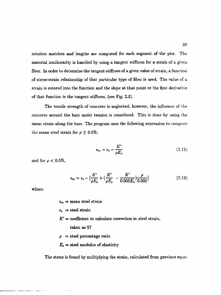
rotation matrices and lengths are computed for each segment of the pier. The
material nonlinearity is handled by using a tangent stiffness for a strain of a given
fiber. In order to determine the tangent stiffness of a given value of strain, a function
of stress-strain relationship of that particular type of fiber is used. The value of a
strain is entered into the function and the slope at that point or the first derivative
of that function is the tangent stiffness, (see Fig. 2.3).
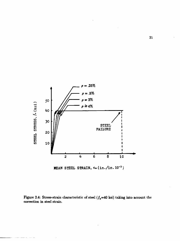
The tensile strength of concrete is neglected; however, the influence of the
concrete around the bars under tension is considered. This is done by using the
mean strain along the bars. The program uses the following expression to compute
the mean steel strain for p > 0.5%:
e m = e , -^r (2 . IS) P&3
and for p < 0.5%,
,K' ,K' K' p . ,n ,A . C m _ C s lpE. + (pE. 0 .005£^ 0 .005^ ( ^
where:
em = mean steel strain
£j = steel strain
K' — coefficient to calculate correction in steel strain,
taken as 57
p = steel percentage ratio
E, = steel modulus of elasticity
The stress is found by multiplying the strain, calculated from previous equa-

STRAIN
Figure 2.3: Tangent stiffness of a fiber.

30
tions, by the modulus of the steel. If the computed stress exceeds the yield stress,
the stress is taken as the yield stress. PIER arbitrarily considers fracture in the
steel if a fiber strain reaches 1%. Fig. 2.4 shows a family of curves with different
steel percentages for a yield stress of 40 ksi calculated by using equations 2.18 and
Two different concrete stress-strain curves are used; one for unconfined con
crete (see Fig. 2.5) and one for confined concrete (see Fig. 2.6).
The effect of load duration or sustained load effects on the pier is considered
by using a modification of the short-time stress-strain relationship for concrete. A
procedure suggested by Chovichien et al. (1973) is used. The modification consists
of expressing the maximum compressive stress for concrete and the concrete strain
corresponding to maximum stress in terms of logarithmic function of time. The
expressions used in the program are:
2.19.
f!(t) = 0.85/; (2.20)
for t< 730 days:
eD(t) = 0.002 + 0.00085 ln(i + 1) (2.21)
and for t > 730 days:
e0(t) = 0.0076 + .000375 ln(tf - 730) (2.22)
where:
f 'c
t
= standard compressive cylinder strength for concrete
= time under sustained loading in days
31
p = .25%
p = .5%
p — 4%
STEEL FAILURE
MEAN STEEL STRAIN, «n»(in./in. 10"3)
Figure 2.4: Stress-strain characteristic of steel (/„=40 ksi) taking into account the correction in steel strain.

32
k = 0.85 for vertically cast columns
k = 0.95 for horizontally cast columns
f /:
€u = .0038
STRAIN
Figure 2.5: Hognestad stress-strain curve.

33
= 0.95 for confined concrete
/. = /"(l - ">(« - <„)]
m as 20
/ c=/ re - ( i ) J ]
= 0.003 +0.02*+ $&]2
= ZZw"yfJ»
COMPRESSIVE STRAIN (in./in.)
Figure 2.6: Compressive stress-strain curve of confined concrete from Ford.

34
and eu, ultimate strain in concrete, is given by:
6 „(*) = 1.9e0(t) (2.23)
which is equal to 0.0038 when no time effects are considered. Comparisons were
made with test results and the computer program and were found to be in agreement
with each other (Gilliam et al. 1983).
Poston et al. also developed an extension of program PIER called FPIER.
The program, FPIER, analyzes rectangular frames with symmetrical configurations
of up to two bays and three stories. As program PIER does, FPIER also manipulates
a diversity of cross section shapes and variations along the member axis.
The loading is assumed static and monotonic and it is applied in increments.
The fiber model is also used in the program FPIER. Each member of the frame
is divided into a specified number of longitudinal segments. Each segment is then
divided into a number of equal sections for purposes of computing the stiffness
matrix of the segment. When the segment stiffness matrix is calculated, it is used to
assemble the member stiffness matrix which is then rotated into global coordinates
and added to the frame stiffness matrix. The stiffness matrix is gathered for every
load increment and the cyclic process is repeated until all increments of load have
been applied to the structure or until failure occurs. The failure occurs when there
is material failure, or when a negative stiffness occurs signalling a plastic hinge
formation or when there has been a stability failure. The program assumed a
concrete compression failure if any fiber strain exceeds the specified ultimate strain
of concrete, and a tensile failure is assumed if any steel fiber strain exceeds 1%.
All nonlinear effects are included in the formulation and they follow the same

35
approach used in program PIER. Program FPIER was checked against a number of
frame results. The analytical predictions were in good agreement with experimental
data up to the development of full plastic hinging (Gilliam et al. , 1983).
In 1984, Diaz developed a computer program to analyze the stability effects
on typical frames. The program is based on a complex fiber model. Diaz uses the
word complex to differentiate his formulation from the fiber model used by Poston
et al. which also accounts for all nonlinear effects, but uses some approximations to
generate the effects of nonlinear geometry. In the complex fiber model, the nonlin
ear effects are all already included in the formulation and therefore no modifications
are required. In fact, Diaz compared several experimental load-deformation frame
responses with the complex fiber model and the fiber model predictions. He found
that in all cases the ultimate capacity was very well predicted by both the fiber
model and the complex fiber model, even though there were some discrepancies
between the analytical and the experimental load-deformation curves. Diaz consid
ered that the load-deformation behavior is predicted better by the complex fiber
model particularly close to the ultimate capacity of the frame.
The program uses a tangent stiffness formulation and it is based on large
deformation theory. Each member of the frame is divided into segments, which can
be of unequal lengths and can have different types of cross sections. Each cross
section is subdivided into fibers to obtain the stiffness matrix of the member. The
loading is assumed to be static and monotonic, and the desired load for the structure
is applied in increments.
To account for material nonlinearities, an elasto-plastic model for the steel, a
Hognestad stress-strain curve (Hognestad,1951) for unconfined concrete, and a Ford

36
stress-strain curve (Ford,1977) for confined concrete, are used in the formulation.
Diaz studied the behavior of a number of frames subjected to combination of
vertical, and lateral loads. Comparisons were made between the numerical results
and those of approximate methods, such as the Moment Magnifier (current ACI code
approach), the Additional Moment Method (current CEB/FIB code approach) and
the Stability Index Method. The comparisons were accomplished in two different
ways. The first way compared the predicted analytical moments with the design
moments from the approximate methods mentioned previously. The second way
compared the predicted analytical capacity of each frame with the design capacity
obtained from the approximate methods.
From this study, Diaz concluded that the three approximate methods pre
dicted reasonable values of design moments for the cases having symmetrical axial
loads. The Moment Magnifier and the Q-Index method tend to underestimate the
moments when the axial loads are unsymmetrically distributed. However, the Ad
ditional Moment Method (CEB/FIB) gave reasonable estimates of the moments for
cases of story columns not having the same axial loads.
From the comparisons of predicted capacity, the Additional Moment Method
was found to be very conservative for both symmetrically and unsymmetrically ap
plied axial loads. The method becomes more conservative when the axial load in
creases. The Moment Magnifier (ACI 318-83) and the Q-Index method predicted
similar capacities. Both were conservative, up to 20%, for the case of symmetrically
applied axial loads. In the case of unsymmetrically applied axial loads, both meth
ods showed a zone where the results were slightly unconservative, by no more than
10%.

37
CHAPTER 3
Computer Program FPIER
Some general features about the formulation of program FPIER (Poston
et al., 1983), was presented in the previous chapter. FPIER is based on the fiber
model. Its primary objective is the structural analysis of reinforced concrete frames.
It handles the member cross sections shown in Fig. 3.1. FPIER can also treat
assemblage of straight, tapered, or flared columns.
The main assumption in the formulation of program FPIER is that small
changes in displacement can be linearly related to small changes in force, and that
plane sections before bending remains plane after bending. The main limitations
are that the frame must be rectangular and geometrically symmetrical in elevation
with a maximum of two bays and three levels.
The program input can be summarized in five major areas:
• Geometry of the structure
• Member properties
• Boundary conditions
• Information about the segments required
• Loading systems

RECTANGULAR SOLID
RECTANGULAR HOLLOW
RECTANGULAR CELLULAR
CIRCULAR SOLID
CIRCULAR HOLLOW
<s> OVAL
SOLID
Figure 3.1: Cross section shapes and reinforcement position.
39
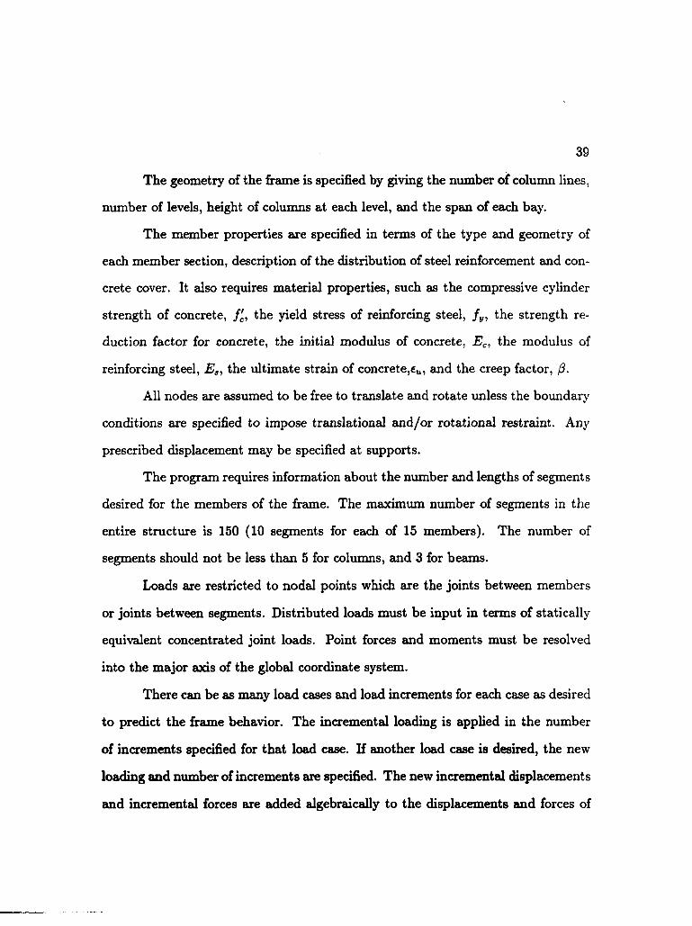
The geometry of the frame is specified by giving the number of column lines,
number of levels, height of columns at each level, and the span of each bay.
The member properties are specified in terms of the type and geometry of
each member section, description of the distribution of steel reinforcement and con
crete cover. It also requires material properties, such as the compressive cylinder
strength of concrete, f'c, the yield stress of reinforcing steel, fy, the strength re
duction factor for concrete, the initial modulus of concrete, Ec, the modulus of
reinforcing steel, Ea, the ultimate strain of concrete,eu, and the creep factor, /?.
All nodes are assumed to be free to translate and rotate unless the boundary
conditions are specified to impose translational and/or rotational restraint. Any
prescribed displacement may be specified at supports.
The program requires information about the number and lengths of segments
desired for the members of the frame. The maximum number of segments in the
entire structure is 150 (10 segments for each of 15 members). The number of
segments should not be less than 5 for columns, and 3 for beams.
Loads are restricted to nodal points which axe the joints between members
or joints between segments. Distributed loads must be input in terms of statically
equivalent concentrated joint loads. Point forces and moments must be resolved
into the major axis of the global coordinate system.
There can be as many load cases and load increments for each case as desired
to predict the frame behavior. The incremental loading is applied in the number
of increments specified for that load case. If another load case is desired, the new
loading and number of increments are specified. The new incremental displacements
and incremental forces are added algebraically to the displacements and forces of

the previous loading for other load cases.
The output from FPIER consists of the printout of incremental results that
includes displacements and rotations at each joint, and the forces and moments at
the end of each segment for each member. The analysis is finished when the load
increments have been completed, when there is an assumed material or stability fail
ure, or when a negative stiffness occurs signalling a plastic hinge formation. When
the frame undergoes any of these types of failures, the displacements and forces,
for the last increment before failure, are printed. A listing of the program, FPIER,
and a sample input/output are presented in Appendix A and B, respectively.

41
CHAPTER 4
Parametric Study
MacGregor, 1970, suggested that the following variables have the most effect
on the strength and behavior of slender columns: slenderness ratio, l/h; shape of
cross section and reinforcement position; reinforcement ratio, pt] ratio of distance
between the outer reinforcement layers and the overall thickness, 7; and eccentricity,
e/h. MacGregor also performed studies on the interaction of columns and beams in
a slender unbraced frame. He suggested that an increase in the degree of rotational
restraint at the ends of the columns by increasing the beam stiffness will always
increase the strength of the columns, unless, of course, the restraints yield. There
fore, it is essential that the design of beams in a frame that is free to sway reflects
the magnified moment developed at the column ends.
In the present study, a single bay fixed-base portal frame as shown in Fig.
4.1 was used as a frame model configuration. Some of the dimensions of the frame
model were inspired by an actual bridge design in Tucson, Arizona. However, the
following variables were selected for the purpose of the analysis:
• Shape of column cross section: circular and rectangular
• Column reinforcement ratio, p: 1, 3, and 5%
• Slenderness ratio, klu/r: 30, 50, and 70

Figure 4.1: Frame configuration used in the analysis.

where k is the effective-length factor for compression member, lu is the un
supported length of the column, and r is the radious of gyration.
• Axial load intensity, P/P0: 0.1, 0.3, 0.5, and 0.7
where P is the actual axial load applied, and PQ is the strength of the column
in pure compression.
• Ratio of flexural stiffness, EcIcoi/EcI{,eam: 0.23, and 1.18
where Ec is the modulus of elasticity of concrete, and Icoi and heam are the
moment of inertia of the gross cross sections of the column and beams, re
spectively.
• Distribution of total axial load: symmetrical and unsymmetrical loading.
In the symmetrical loading case, each column of the frame shown in Fig. 4.1
was loaded with an axial load, P, of 0.1Po, 0.3Po, 0.5P0, and 0.7P0. In the
unsymmetrical loading case only the right column was loaded with a total
axial load of P. In this case the values of P used were: 0.2P0 and 0.6Po.
Using the computer program FPIER, a parametric study was performed on
different combinations of variables that have been chosen. A total of 216 cases of
frames with a total of four different sets of beam and column cross sections were
analyzed. Ifeble 4.1 shows the dimensions of the beam and column cross sections
used. In this table, C-L indicates the set of beam and column cross sections used
in frames having circular column cross sections (C) and low flexural stiffness ratio
(L) of 0.23. The beam and column cross sections under the name C-H were used
in the frames having circular column cross sections (C) and high flexural stiffness

44
ratio (H) of 1.18. Similarly, R-L and R-H are the sets of beam and column cross
sections used in frames with rectangular column cross sections (R), and with low
and high flexural stiffness ratio of 0.23 and 1.18, respectively.
From the parametric study, the internal analytical moments at the four cor
ners of each frame were obtained. Then, comparisons were made between the pre
dicted analytical moments and the design moments predicted by the Moment Mag
nifier Method of the American Concrete Institute Code (ACI 318-83). To obtain
the predicted analytical moments, each member of each frame was divided into 10
segments of equal length, (see Fig. 4.2). A given set of vertical loads was applied
in one increment to the columns of the frame, followed by an incrementally lateral
load, H, applied to the west knee of the frame, until failure was reached.
In order to reduce the complexity of the analysis, the following parameters
were maintained constant:
• Shape of beam cross section: rectangular
• Doubly reinforced beam: p — 1% and p' = 1%
where p and p' are the percentage of steel reinforcement in the tension and
compression zone respectively.
• Bay span: 28 feet
• Concrete compressive strength, /c': 4000 psi
• Strength reduction factor for concrete: 0.85
• Modulus of elasticity of concrete, Ec: 3600 ksi

Table 4.1: Beam and columns cross section dimensions.
Cross Section Dimensions C-L C-H R-L R-H
hb (in.) 2h k8 zh
(in.) 96 96 ^8
K (in.) - - 31
«>e (in.) - - 35 26
<*c (in.) ^5 3k - -

46
Figure 4.2: Number of segments used.

47
• Tensile yield strength of reinforcing steel, f y : 60000 psi
• Modulus of elasticity of steel, Es\ 29000 ksi
• Distance from extreme fiber of section to center of steel : 3 in
• No creep or sustained load effect was considered
Once the results from the computer program were obtained, the evaluation
of design moments, using the Moment Magnifier method, was carried out. This
was done based on an elastic analysis using gross cross section properties. The
magnifier factors 6b, and 8, in equation 2.1 (for braced and unbraced conditions)
d e p e n d p r i m a r i l y o n t h e e v a l u a t i o n o f t h e f a c t o r k a n d t h e s t i f f n e s s p a r a m e t e r E I .
The values of k were calculated using alignment charts based on the gross cross
section of the column, neglecting the steel reinforcement, and using half of the
flexural stiffness of the beam (0.5EcIg) also neglecting the steel reinforcement. The
stiffness parameter, EI, needed to calculate the elastic critical loads (Eqs. 2.3 and
2.6) was estimated by using EcIg/2.5 in the cases when p = 1% and EcIg/5 + EsIse
in the cases when p = 3% and 5%.
The results from the computer program, together with the prediction from
the ACI code for each frame were plotted in a common graph. Examples of these
plots are shown in Figs. 4.3, 4.4, and 4.5.
Each one of the 216 frames was named according to the following rules: The
first letter indicates the shape of the column cross section which can be rectangular
(R) or circular (C). The number following the first letter indicates the percentage
of steel reinforcement in the column. It can be 1, 3, or 5. The letter in the third
position means the ratio of flexural stiffness. It can be 0.23 represented by L (for low)

R5L3PP0.3 ACI
o Mo x Mb + Mc * Md
100-
75-
50-
25-
400 600
Horizontal load, H(kips)
200 800 1000
Figure 4.3: Comparison of the ACI Moment Magnifier Method predictions with measured moments at the four corners of the frame R5L3PP0.3 for various horizontal loads.

C5H3P0.2 ACI
o Ma x Mb + Mc * Md
40-
Q. 30-
20-
1 0 -
100 200 300 400
Horizontal load, H(kips)
500
Figure 4.4: Comparison of the ACI Moment Magnifier Method predictions with measured moments at the four corners of frame C5H3P0.2 for various horizontal loads.

C3L5PPQ.5 ACI
o Ma x Mb + Mc • Md Q.
90
25
50 100 150
Horizontal load, H(kips)
250 200 300
Figure 4.5: Comparison of the ACI Moment Magnifier Method predictions with measured moments at the four corners of frame C3L5PP0.5 for various horizontal loads.

51
or 1.18 represented by H (for high). The following number indicates the slenderness
ratio: a number 3 is used for a nominal klu/r of 30, 5 for Klu/r of 50, and 7 for
klu/r of 70. The following letters (PP) indicate a symmetrical distribution of the
vertical load (one load P applied to each column simultaneously). In the cases of
unsymmetrical distribution, only one (P) is used, indicating that only the right
column is subjected to a load P. Finally, the last number indicates the intensity of
the axial load, P/P0, applied. It could be 0.1, 0.3, 0.5, and 0.7 for the symmetrical
loading cases or 0.2, and 0.6 for the unsymmetrical loading cases.
For example, the graph in Fig. 4.3, called R5L3PP0.3, corresponds to a frame
with rectangular column cross section having 5% of reinforcement. The frame has
low flexural stiffness ratio, 0.23, and a slenderness ratio of approximately 30. Two
symmetrical axial loads are applied to the columns of the frame, each one having
a magnitude of 0.3P„. This graph shows the variation of the moment in the four
corners of the frame (points a, b, c, and d), obtained from the computer analysis
and the design moment predicted by the ACI code as a function of the lateral
load, H. The variation of the analytical moments, with respect to the lateral load,
H, is almost linear in each corner of the frame, having the larger values at point
'a' and 'd\ The maximum moment predicted by the computer analysis was 87500
kip-in at point'd' while the ACI code method predicted a moment equal to 87300
kip-in which is in good agreement. This frame had a material failure at point'd'.
The graph in Fig. 4.4 belongs to the frame C5H3P0.2. This frame has circular
column cross sections with a reinforcement ratio of 5%. The frame has high flexural
stiffness ratio, 1.18, and a slenderness ratio of approximately 30. Only the right
column is axially loaded with a load P equal to 20 percent of the nominal axial

strength of the column. In this case there is more discrepancy between the moments
at the upper corners than with the moments at the bottom corners. A higher
moment of 32100 kip-in was obtained from the computer analysis at point'd'. The
ACI code underestimates the value of the moment predicting a moment equal to
27600 kip-in, about 14% less than the analytical prediction. This frame had a
material failure at point'd'.
Finally, Fig. 4.5 shows the results of the frame C3L5PP0.5. This frame
has circular column cross section with 3% of steel reinforcement. It has a flexural
stiffness ratio of 0.23 and a slenderness ratio of about 50. Both columns are axially
loaded, each one with a load P of 50 percent of the nominal axial strength of the
column. In this case, the ACI method overestimates the moment in the frame
by predicting a stiffer frame (greater slope). The prediction from the computer
analysis was 51300 kip-in at point 'a', while the ACI code predicted a moment
equal to 71900 kip-in, about 40% more than the analytical moment. This frame
also failed by material failure at point'd'.

53
CHAPTER 5
Analysis of Results
The results from the parametric study axe presented and analyzed in this
chapter. Each one of the 216 cases studied are represented by a ratio ACI/Analysis.
'ACI' represents the design moment predicted by the Moment Magnifier Method
of the American Concrete Institute Code (ACI 318-83), and 'Analysis' represents
the higher moment found at the four corners of the frame at failure, obtained from
the computer analysis which is considered the 'exact' solution. The ratio of these
two moments, ACI/Analysis, would then measure the accuracy of the ACI code
approach against the exact solution. A value of ACI/Analysis less than 1.0 would
indicate that the ACI code method underestimates the value of the moment in
the frame predicting a maximum moment for a given value of lateral load which
is smaller than the actual one; i.e. the ACI approach is unconservative. A value
greater than 1.0 would indicate that the ACI code method overestimates the actual
moment in the frame, i.e. the ACI approach is conservative. Finally, a value
of ACI/Analysis equal to the unity would, therefore, indicate excellent agreement
with the exact solution.
In the following sections, the accuracy of the ACI Moment Magnifier Method
is studied according to each one of the variables chosen in the parametric study:
axial load intensity, P/P0\ percentage of steel, p; slenderness ratio, fc/u/r; shape of

54
column cross section, and ratio of flexural stiffness. The analysis of the results for the
symmetrical and unsymmetrical vertical loading patterns axe presented separately.
A single asterisk (*), located in any of the tables presented in this chapter,
indicates that the solution of the computer program was neglected due to excessive
lateral deformation in the frame, or due to sudden stability failure when the vertical
loads were applied. A double asterisk (* *) indicates that the Moment Magnifier
Method predicts too large or negative sway magnifier factor, 6a, which means that
the frame is unstable.
5.1 Symmetrical Vertical Loading Pattern
5.1.1 Analysis according to the axial load intensity, P/P0:
Tables 5.1 through 5.4 shows the variations of the ratio ACI/Analysis with
respect to the level of axial load ( P/P0 ) for different percentages of steel ( p ). In
order to analyze the behavior of ACI/Analysis in relation to P/P0, it was necessary
to arrange them in different tables according to the other parameters. For instance,
Table 5.1 shows the ratio ACI/Analysis for frames having circular column cross
section, flexural stiffness ratio of 0.23, and slenderness ratio of 30, 50, and 70 (C-
L-30, C-L-50, and C-L-70, respectively). The ratio ACI/Analysis increases from
left to right at a given percentage of steel. For example, the frame C-L-30 with p
equal to 1% has ACI/Analysis ratios of 0.98, 1.06, 1.13, and 1.17 for levels of axial
loads ( P/P0) of 0.1, 0.3, 0.5, and 0.7 respectively. This denotes that the ACI code
method tends to be more conservative when the level of axial load increases. This
trend of variation was found in every case of Table 5.1.
Table 5.2 shows the ratio ACI/Analysis of the frames having circular column

55
cross section, a flexural stiffness ratio of 1.18, and slenderness ratio of 30, 50, and 70
(C-H-30, C-H-50, and C-H-70, respectively). A close look at this table would reveal
the increasing behavior of ACI/Analysis when the axial load increases. The ACI
code method predicts 2.96 times the value of the analytical moment for the frame
C-H-50 with />-equal to 1% and P/P0 equal to 0.7, and 2.49 times the analytical
moment for the frame C-H-50 with p equal to 3% and P/P0 equal to 0.7.
Table 5.3 contains the ratio ACI/Analysis of the frames having rectangular
column cross section, flexural stiffness ratio of 0.23, and slenderness ratio of 30,
50, and 70 (R-L-30, R-L-50, and R-L-70, respectively). This table shows the same
increasing variation of ACI/Analysis with an increase in the axial load applied. The
ACI method predicts more than two times the value of the actual moment in the
frame R-L-50 with p = 1% and P/P0 = 0.7. It also predicts twice the value of the
analytical moment in the case R-L-70 with p = 3% and P/P0 = 0.5.
Finally, Table 5.4 shows the ratio ACI/Analysis of the frames having rect
angular column cross section, flexural stiffness ratio of 1.18, and slenderness ratio
of 30, 50, and 70 (R-H-30, R-H-50, and R-H-70, respectively). Again, the same
trend was found. The ACI code method overestimates the moment in the frames
(becomes conservative) when the level of axial load increases.
5.1.2 Analysis according to the percentage of steel, pi
The Tables 5.1 through 5.4 are also used to analyze the behavior of the
ACI/Analysis with respect to the percentage of steel for the symmetrical vertical
loading pattern. Tbble 5.1 shows the variation of ACI/Analysis ratio in relation to
the percentage of steel for frames having characteristics C-L-30, C-L-50, and C-L-70.

56
Table 5.1: ACI/Analysis ratios vs. P/P0 and p for frames with circular column cross section and flexural stiffness ratio of 0.23 in a symmetrical vertical loading pattern.
C-L-30
p(*T\ 0 . 1 0 . 3 0 . 5 0 . 7
i 0 . 9 8 1 . 0 6 1 . 1 3 1 . 1 7
3 0 . 9 9 1 . 0 5 1 . 0 9 1 . 1 1
5 0 . 9 9 1 . 0 2 1 . 0 5 1 . 0 6
C-L-50
N /?. 0 . 1 0 . 3 0 . 5 0 . 7
1 0 . 9 8 1 . 1 7 1 - 5 1 •
3 1 . 0 1 1 . 1 8 1 . 4 0 1 . 7 3
5 1 . 0 0 1 . 1 2 1 . 2 5 1 . 4 0
C-L-70
0 . 1 0 . 3 0 . 5 0 . 7
i 0 . 9 8 1 . 5 8 • • • •
3 1 . 0 4 1 . 5 3 • • • •
5 1 . 0 4 1 - 3 4 2 . 2 5 • •

57
Table 5.2: ACI/Analysis ratios vs. P/P 0 and p for frames with circular column cross section and flexural stiffness ratio of 1.18 in a symmetrical vertical loading pattern.
C-H-30
0 . 1 0 . 3 0 . 5 0 . 7
i 1 . 0 9 1 . 1 0 1 . 1 6 1 . 2 4
3 1 . 0 0 1 . 0 2 1 . 0 8 1 . 1 7
5 0 . 9 3 0 . 9 6 1 . 0 0 1 . 0 6
C-H-50
0 . 1 0.3 0 . 5 0 . 7
1 1 .09 1 .30 1 . 7 5 2 . 9 6
3 1 .00 1 .15 1 . 5 7 2 . 4 9
5 0.92 1 . 0 4 1 . 2 1 1 . 6 9
C-H-70
0 . 1 0 . 3 0 . 5 0 . 7
1 1 . 1 1 1 . 7 2 • • * »
3 1 . 0 6 1 - 3 9 e » * •
5 1 . 0 8 2 . 3 3 • • • #

58
Table 5.3: ACI/Analysis ratios vs. P/P 0 and p for frames with rectangular column cross section and flexural stiffness ratio of 0.23 in a symmetrical vertical loading pattern.
R-L-30
0 . 1 0 . 3 0 . 5 0 . 7
1 0 . 9 6 1 . 0 5 1 . 1 3 1 . 1 6
3 0 . 9 ^ 1 . 0 3 1 . 0 5 1 . 0 6
5 0.9^ 1 . 0 0 0 . 9 9 1 . 0 2
R-L-50
0 . 1 0 . 3 0 . 5 0 . 7
1 0 . 9 7 1 . 2 0 1 . 5 7 2 . 2 2
3 0 . 9 6 1 . 1 2 1 . 2 2 1 . 3 9
5 0 . 9 6 1 . 0 7 1 . 1 3 1 . 1 9
R-L-70
0 . 1 0 . 3 0 . 5 0 . 7
1 0 . 9 7 1 . 7 2 * • # •
3 0 . 9 9 1 . 3 3 2 . 0 0 * *
5 0 . 9 8 1 . 2 0 1 . 5 6 •

59
Table 5.4: ACI/Analysis ratios vs. P/P 0 and p for frames with rectangular column cross section and flexural stiffness ratio of 1.18 in a symmetrical vertical loading pattern.
R-H-30
0 . 1 0 . 3 0 . 5 0 . 7
i 1 . 0 6 1 . 0 7 1 . 1 3 1 . 1 9
3 0 . 9 6 0 . 9 7 1 . 0 6 1 . 1 4
5 0 . 9 0 0 . 9 3 0 . 9 8 1 . 0 2
R-H-50
0 . 1 0 . 3 0 . 5 0 . 7
i 1 . 0 6 1 . 2 6 1 . 6 8 2 . 7 5
3 0 . 9 6 1 . 1 5 1 . 5 6 2 . 5 8
5 0 . 9 0 1 . 0 2 1 . 2 5 1 . 7 6
R-H-70
0 . 1 0 . 3 0 . 5 0 . 7
l 1 . 1 3 1 . 9 6 • • • •
3 1 . 0 5 1 . 8 4 • • • •
5 0 . 9 7 1 . 4 4 • • • •

60
At a given level of axial load, the ACI/Analysis ratio decreases when the percentage
of steel increases (from top to bottom) for most of the cases. For example, for frame
C-L-30 with P/P0 equal to 0.5 the values of ACI/Analysis are 1.13, 1.09, and 1.05
for percentage of steel of 1%, 3%, and 5%, respectively. However, this behavior was
not found when the columns are subjected to low axial load ( P/P0 = 0.1) where
the ratio ACI/Analysis tends to increase slightly when p increases.
In Table 5.2, the values of ACI/Analysis, for frames having circular column
cross section and flexural stiffness ratio of 1.18, are presented. The ACI code method
predicts less conservative values when the percentage of steel, p, increases. However,
in the cases C-H-70 with P/P0 = 0.1 and P/P0 = 0.3 there is a sudden increase of
ACI/Analysis at a p equal to 5%.
The values of ACI/Analysis for frames with rectangular column cross section
and flexural stiffness ratio of 0.23 are shown in Table 5.3. In these cases the ACI code
also predicts less conservative values for high values of percentage of steel except
for the cases of frames R-L-70 with P/P0 equal to 0.1 where the ACI/Analysis ratio
slightly increases when the percentage of steel increases.
The ACI/Analysis ratio for frames with rectangular column cross section
and flexural stiffness ratio of 1.18 are shown in Table 5.4. The ACI code approach
predicts less conservative values when p = 5%. The ACI code, however, is on the
unconservative side in the cases R-H-30 with P/P0 = 0.1 and p = 5%, and R-H-50
with P/P0 = 0.1 and p = 5% predicting, in both cases, moments which are 10%
lower than the actual moments.

61
5.1.3 Analysis according to the slenderness ratio, kl u / r :
The values of ACI/Analysis were rearranged in relation to the slenderness
ratio for a given percentage of steel in order to provide a better look at their be
havior. For example, Table 5.5 contains the ratios ACI/Analysis for frames having
circular column cross section, flexural stiffness ratio equal to 0.23, and levels of
axial loads P/P0 of 0.1, 0.3, 0.5, and 0.7 (C-L-PP0.1, C-L-PP0.3, C-L-PP0.5, and
C-L-PP0.7, respectively).
It can be seen that the ratio ACI/Analysis increases when the slenderness
ratio increases. For instance, in the case C-L-PP0.3 with p = 3%, the values of
ACI/Analysis are 1.05, 1.18, and 1.53 for slenderness ratios of 30, 50, and 70,
respectively, where the ACI code method predicts 53% more than the value of the
analytical moment when klu/r is equal to 70.
Table 5.6 shows the results from the frames having circular column crosss
sections, and flexural stiffness of 1.18 for each one of the level of axial load used. For
almost every case in this table, the ACI/Analysis ratio has an increasing variation
with an increase in the slenderness ratio, especially for higher level of axial loads.
In the same way, Tables 5.7 and 5.8 show the results from frames having
rectangular column cross sections, and flexural stiffness ratios of 0.23 and 1.18,
respectively. Once again, the same behavior was found. The ACI code method
becomes more conservative when the slenderness ratio increases, being more critical
for cases of frames with columns subjected to a high level of axial load.

Table 5.5: ACI/Analysis ratios vs. kl u / r for frames with circular column cross section and flexural stiffness ratio of 0.23 in a symmetrical vertical loading pattern.
C-L-PPO.1 C-L-PP0.3
\«./r 3 0 5 0 7 0
1 0 . 9 8 0 . 9 8 0 . 9 8
3 0 . 9 9 1 . 0 1 1 . 0 4
5 0 . 9 9 1 . 0 0 1 . 0 4
3 0 5 0 7 0
1 1 . 0 6 1 . 1 7 1 . 5 8
3 1 . 0 5 1 . 1 8 1 . 5 3
5 1 . 0 2 1 . 1 2 1 . 3 4
C-L-PPO.5 C-L-PPO.7
*%)
l . l i 1 . 7 3
1 .06
«./r
1 . 5 1 1 . 1 3
1 . 0 9
2 . 2 5 1 . 2 5 1 . 0 5
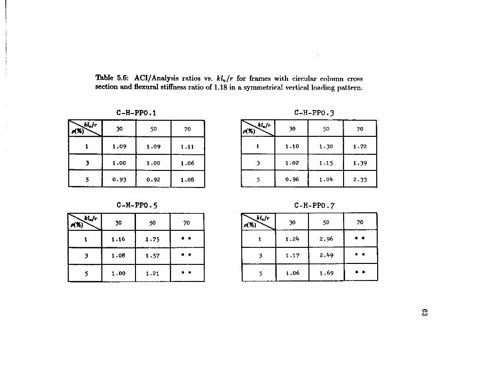
Tbble 5.6: ACI/Analysis ratios vs. kl u / r for frames with circular column cross section and flexural stiffness ratio of 1.18 in a symmetrical vertical loading pattern.
C-H-PP0.1
\H./p 3 0 50 7 0
1 1 . 0 9 1.09 1.11
3 1.00
O
O
H 1 .06
5 0.93 0.92 1 .08
C-H-PP0.5
3 0 5 0 7 0
1 1 . 1 6 1 . 7 5 • •
3 1 . 0 8 1 - 5 7 • •
5 1 . 0 0 1 . 2 1 • •
C-H-PP0.3
30 50 70
1 1.10 1.30 1.72
3 1.02 1.15 1.39
5 0.96 1.0^ 2.33
C-H-PP0.7
\*/./r P(96r^ 3 0 5 0 7 0
1 1 ,2>* 2.96 » •
3 1 . 1 7 2.1*9 • •
5 1 . 0 6 1 .69 • •

Table 5.7: ACI/Analysis ratios vs. kl u / r for frames with rectangular column cross section and flexural stiffness ratio of 0.23 in a symmetrical vertical loading pattern.
R-L-PPO .1 R-L-PPO.3
P(*f\ 3 0 5 0 70 30 5 0 7 0
1 0.96 0.97 0.97 1 1 .05 1 .20 1 . 7 2
3 0 . 9 ^ 0.96 0.99 3 1 .03 1 . 1 2 1 - 3 3
5 0 . 9 ^ 0.96 0.98 5 1.00 1 . 0 7 1 . 2 0
R - L -•PPO.5 R-L-PPO. 7
3 0 50 70 3 0 50 7 0
1 1 . 1 3 1.57 • • 1 1.16 2.22 * *
3 1.05 1 .22 2.00 3 1 .06 1 - 3 9 • •
5 o . 9 9 1 .13 1 .56 5 1 .02 1 . 1 9 •
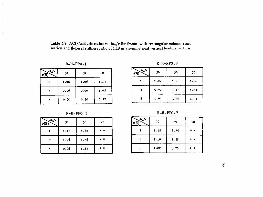
Table 5.8: ACI/Analysis ratios vs. kl u / r for frames with rectangular column cross section and flexural stiffness ratio of 1.18 in a symmetrical vertical loading pattern.
R-H-PPO.1
\H./r 3 0 5 0 70
1 1 .06 1 .06 1 . 1 3
3 0.96 0.96 1 . 0 5
5 0.90 0.90 0 . 9 7
R-H-PPO.5
3 0 5 0 7 0
1 1 . 1 3 1 . 6 8 • *
3 1 . 0 6 1 . 5 6 • *
5 0.98 1 . 2 5 * •
R-H-PPO.3
30 50 70
1 1.07 1.26 1.96
3 0.97 1.15 1.81*
5 0.93 1.02 l . lrt
R-H-PPO.7
3 0 5 0 7 0
1 1 . 1 9 2 . 7 5 • •
3 1 . 1 ^ 2 . 5 8 * *
5 1 . 0 2 1 . 7 6 * *

66
5.1.4 Analysis according to the shape of column cross section:
In order to study the behavior of the ACI code predictions with the shape
of the column cross section, the values of ACI/Analysis ratio were rearranged in
different tables. Tables 5.9 through 5.14 show the ACI/Analysis ratio in relation
to the shape of the column cross section, where C indicates a circular cross section
and R indicates rectangular cross section. Frames with low flexural stiffness (L),
0.23, and slenderness ratio of 30, 50, and 70 are presented in Tables 5.9, 5.10, and
5.11, respectively. In the same manner, frames with high flexural stiffness (H), 1.18,
and slenderness ratio of 30, 50, and 70 are presented in Tables 5.12, 5.13, and 5.14,
respectively.
In most cases of frames in Tables 5.9, 5.10, and 5.11, the ACI/Analysis
ratios axe higher for frames with circular column cross section. However, the values
of ACI/Analysis for circular and rectangular column cross section are still very
close to each other. For example, the frame L-30-PP0.3 with p = 1% has a ratio
ACI/Analysis of 1.06 for circular cross section and 1.05 for rectangular column cross
section. The same behavior was found in the cases of frames shown in Tables 5.12,
5.13, and 5.14. In most cases, the ACI code method tends to predict slightly more
conservative values for frames having circular column cross section.
5.1.5 Analysis according to the flexural stiffness ratio:
Tables 5.15 through 5.20 show the ACI/Analysis ratio in relation to the two
values of flexural stiffness ratio used in the parametric study, 0.23 and 1.18. The
results of frames with circular column cross section and slenderness ratio of 30, 50,
and 70 are presented in Tables 5.15, 5.16, and 5.17, respectively, and those of frames

Table 5.9: ACI/Analysis ratios vs. shape of column cross scction for frames with flexural stiffness ratio of 0.23 and kl u / r of 30 in a symmetrical vertical loading pattern.
L-30-PP0.1 L-30-PP0.3 cross
section p(%)
1.05 1.06
1.03 1.05
1.00 1.02
0.96 0.98
0.99
0.99
L-30-PP0.5 L-30-PP0.7
section Pi%)
1 . 1 6 1 . 1 7
1 .06 1 . 1 1
1.06 1 . 0 2
lion
1 . 1 3 1 . 1 3
1 . 0 5 1 . 0 9
1 . 0 5 0 . 9 9

Table 5.10: ACI/Analysis ratios vs. shape of column cross section for frames with flexural stiffness ratio of 0.23 and kl u / r of 50 in a symmetrical vertical loading pattern.
L-50-PP0.1 L-50-PP0.3
C R
1 0.98 0 .97
3 1 . 0 1 0 .96
5 1 . 0 0 0 .96
\ctojj
C R
1 1 . 1 7 1 . 2 0
3
GO H 1 . 1 2
5 1 . 1 2 1 . 0 ?
L-50-PP0.5 L-50-PP0.7 —^craj* ^^edion C R
1 1 . 5 1 1 . 5 7
3 1 .It 0 1 .22
5 1.25 1 . 1 3
\crojs —-ejection c R
1 * 2 . 2 2
3 1 . 7 3 1 . 3 9
5 1 AO 1 . 1 9

Tbble 5.11: ACI/Analysis ratios vs. shape of column cross section for frames with flexural stiffness ratio of 0.23 and kl u / r of 70 in a symmetrical vertical loading pattern.
L-70-PP0.1 L-70-PP0.3 cross
0.98 0 . 9 7
0 . 9 9
1.Ok 0 . 9 8
^section
1 .58 1 . 7 2
1 - 5 3 1 . 3 3
1 . 2 0
L-70-PP0.5 L-70-PP0.7 cross cross
lection
2.00
1 . 5 6

Table 5.12: ACI/Analysis ratios vs. shape of column cross section for frames with flexural stiffness ratio of 1.18 and kl u / r of 30 in a symmetrical vertical loading
pattern.
H-30-PP0.1 H-30-PP0.3
\CTMI
P(*) c R
1 1.09 1.06
3 1.00 0.96
5 0.93 0.90
\crow c R
1 1.10 1.07
3
CM O 0 .97
5 0.96 0.93
H-30-PP0.5 H-30-PP0.7
Nffon c R
1 1.16 1.13
3 1.08 1.06
5
O
O
H 0.98
\croji c R
1 1.24 1.19
3 1.17 1.14
5 1.06 1.02

Table 5.13: ACI/Analysis ratios vs. shape of column cross section for frames with flexural stiffness ratio of 1.18 and kl u / r of 50 in a symmetrical vertical loading
pattern.
H-50-PP0.1 H-50-PP0.3 —^crost p(%) C R #K%) c R
1 1 . 0 9 1 . 0 6 1 1.30 1 . 2 6
3 1 . 0 0 0 . 9 6 3 1 . 1 5 1 . 1 5
5 0 . 9 2 0 . 9 0 5 1 .ob 1 . 0 2
H--50-PP0. 5 H -50-PP0.
c R scrwa
P(%) c R
1 1 . 7 5 1 . 6 8 1 2.96 2 . 7 5
3 1 - 5 7 1 . 5 6 3 2.49 2 . 5 8
5 1 . 2 1 1 . 2 5 5 1 .69 1 . 7 6

Table 5.14: ACI/Analysis ratios vs. shape of column cross section for frames with fiexural stiffness ratio of 1.18 and kl u / r of 70 in a symmetrical vertical loading pattern.
H-70-PP0.1 H-70-PP0.3
\CTflll (W>) C R
1 1 . 1 1 1 . 1 3
3 1 . 0 6 1 . 0 5
5 1 . 0 8 0 . 9 7
\CTOM c R
1 1 . 7 2 1 . 9 6
3 1 . 3 9 1 . 8 4
5 2 . 3 3 1 . 4 4
H-70-PP0.5 H-70-PP0.7
C R
1 * * * *
3 * # • •
5 • * * *
V^CTMJ /(
ssjedion C R
1 * * * »
3 * * * •
5 * * * *
to

73
with rectangular column cross section, are presented in Tables 5.18, 5.19, and 5.20.
In the cases of frames shown in Tables 5.15 through 5.17, there was no specific
trend of variation of the ACI/Analysis ratio with respect to the flexural stiffness
ratio. In almost half of these cases the ACI code method predicted more conservative
values when 1.18 is used, and for the other half the ACI code predicted more
conservative values when the flexural stiffness ratio of 0.23 is used. In the cases of
frames with rectangular cross section (Tables 5.18 - 5.20), again no specific pattern
was found. However, in most cases, the ACI code predicted more conservative
values when the flexural stiffness ratio of 1.18 was used.
5.2 Unsymmetrical Vertical Loading Pattern
5.2.1 Analysis according to the axial load intensity, P/P0'
Tables 5.21, 5.22, 5.23, and 5.24 present the values of ACI/Analysis ratio
i n relation to the level of axial load (P/P0) and the percentage of steel (p) for
frames unsymmetrically loaded (only the right column was axially loaded). Table
5.21 shows the results of frames with circular column cross section, low flexural
stiffness ratio of 0.23, and slenderness ratio of 30, 50, and 70 (C-L-30, C-L-50, and
C-L-70, respectively). In this table, the ACI/Analysis ratios corresponding to an
axial load of 60% of the nominal column compressive strength (P/P0 = 0.6) are
higher than those corresponding to PJP0 = 0.2. The ACI code method, however,
underestimates the moment in some cases, such as in the case C-L-30 with p = 1%
and P/P0 = 0.2 where the prediction from the code method was 21% less than the
value of the analytical moment predicted. It also underestimates the moment in
the case C-L-30 with p = 1% and P/P0 = 0.6 where the prediction was 14% less
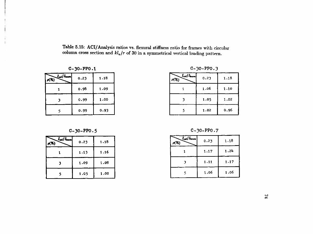
Table 5.15: ACI/Analysis ratios vs. flexural stiffness ratio for frames with circular column cross section and kl u / r of 30 in a symmetrical vertical loading pattern.
C-30-PP0.1 C-30-PP0.3
0.23 1 . 1 8
1 0.98 1 . 0 9
3 0 . 9 9 1 . 0 0
5 0 . 9 9 0 . 9 3
0.23 1 . 1 8
1 1 .06 1 . 1 0
3 1 . 0 5 1 . 0 2
5 1 . 0 2 0 . 9 6
C-30-PP0.5 C-30-PP0.7
0.23 1 . 1 8
1 1 . 1 3 1 . 1 6
3 1 . 0 9 1 . 0 8
5 1 . 0 5 1 . 0 0
0.23 1 . 1 8
1 1 . 1 7 1 ,2k
3 1 . 1 1 1.17
5 1 .06 1.06

Table 5.16: ACI/Analysis ratios vs. flexural stiffness ratio for frames with circular column cross section and kl n / r of 50 in a symmetrical vortical loading pattern.
C-50-PP0.1 C-50-PP0.3
"" ' Jctll 0.23 1 . 1 8
1 0.98 1 . 0 9
3 1 . 0 1
O
O
5 1 .00 0 . 9 2
'learn 0.23
CO
1 1 . 1 7 1 . 3 0
3 1 . 1 8 1 . 1 5
5 1 . 1 2 1 ,0k
C-50-PP0.5 C-50-PP0.7
k m 0.23 1.18
1 1 . 5 1 1 . 7 5
3 l . i f O 1 . 5 7
5 1.25 1.21
'team 0.23 1 . 1 8
1 * 2.96
3 1 . 7 3 2 . ^ 9
5 1 . U o 1 .69

Table 5.17: ACI/Analysis ratios vs. flexural stiffness ratio for frames with circular column cross section and kl u / r of 70 in a symmetrical vertical loading pattern.
C-70-PP0.1
0.23 1.18
1 0.98 1.11
3 l.Ofc 1.06
5 1.01* 1.08
C-70-PP0.5
0.23 1.18
1 • • * •
3 » • • *
5 2.25 * •
C-70-PP0.3
Aeant 0.23 1 . 1 8
1 1 . 5 8 1 . 7 2
3 1 - 5 3 1 . 3 9
5 1 . 3 ^ 2 . 3 3
C-70-PP0.7
/lc«m 0.23 1 . 1 8
1 * * * #
3 * * • •
5 • * * *
^1 0

Table 5.18: ACI/Analysis ratios vs. flexural stiffness ratio for frames with rectangular column cross section and kl u / r of 30 in a symmetrical vertical loading pattern.
R-30-PP0.1 R-30-PP0.3
0.23 1.18
1 0 . 9 6 1 . 0 6
3 0 . 9 ^ 0 . 9 6
5 0 . 9 ^ 0 . 9 0
Aeam 0.23 1 . 1 8
1 1 . 0 5 1 . 0 ?
3 1 .03 0 . 9 7
5 1 .00 0 . 9 3
R-30-PP0.5 R-30-PP0.7
>SsS/«|/Aimi 0.23 1 . 1 8
1 1 . 1 3 1 . 1 3
3 I.05 1 . 0 6
5 0 . 9 9 0 . 9 8
Vsss rf/ Ilemm 0.23 1 . 1 8
1 1 . 1 6 1 . 1 9
3 1 .06 1 . 1 ^
5 1 .02 1 .02

Table 5.19: ACI/Analysis ratios vs. flexural stiffness ratio for frames with rectangular column cross section and kl u / r of 50 in a symmetrical vertical loading pattern.
R-50-PP0.1 R-50-PP0.3
1 . 1 8 0 . 2 3
1 . 2 6 1 . 2 0
1 . 1 5 1 . 1 2
1 . 0 2 1 . 0 7
1 . 1 8 0 . 2 3
1.06 0 . 9 7
0 . 9 6 0 . 9 6
0.96 0 . 9 0
R-50-PP0.5 R-50-PP0.7
1 .18 0 . 2 3
2 . 7 5 2 . 2 2
1 . 3 9
1 . 7 6 1 . 1 9
1 .18 0.23
1 .68 1 . 5 7
1 .22
1 . 2 5 1 . 1 3

Table 5.20: ACI/Analysis ratios vs. flexural stiffness ratio for frames with recta,n-guar column cross section and kl u / r of 70 in a symmetrical vertical loading pattern.
R-70-PP0.1 R-70-PP0.3
0.23 1.18
1 0.97 1.13
3 0.99 1.05
5 0.98 0.97
0.23 1 . 1 8
1 1 . 7 2 1 . 9 6
3 1 . 3 3 1 . 8 ^
5 1 .20 l . W
R-70-PP0.5 R-70-PP0.7
0.23 1 . 1 8
1 • • • •
3 2.00 * •
5 1 . 5 6 • •
Amu 0 . 2 3 1 . 1 8
1 • • • *
3 # * * »
5 • * •
-4 CO

80
than the value of the actual moment. On the other hand, the ACI code method
overestimates the moments predicted in the cases C-L-50 with P/P0 = 0.6 where
the values predicted are 42%, 60%, and 49% greater than the values of the actual
moments corresponding to each one of these cases.
Table 5.22 shows the ACI/Analysis ratio corresponding to frames having
circular column cross section, flexural stiffness ratio of 1.18, and slenderness ratio of
30, 50, and 70 (C-H-30, C-H-50, and C-H-70, respectively). The Moment Magnifier
Method predicts more conservative values when P/P0 is equal to 0.6 especially
in cases C-H-50. However, the predictions were in the unconservative side in some
other cases. For example, cases C-H-30, with an axial load level (P/P0) of 0.2 where
the predictions, were 12% and 14% less than the analytical moment predictions for
p equal to 1 and 5%, respectively.
Table 5.23 shows the results of frames having rectangular column cross sec
tion, flexural stiffness ratio of 0.23, and slenderness ratio of 30, 50, and 70 (R-L-30,
R-L-50, and R-L-70, respectively). Again, the ratio ACI/Analysis is higher in the
cases with P/P0 of 0.6; however, the predictions from the ACI code were uncon
servative in some cases and conservative in other cases. The most imconservative
value was predicted in the case R-L-30 with p equal to 1% and P/P0 equal to 0.2
where the moment predicted was 24% less han the value of the analytical moment,
and the most conservative one was in the case R-L-70 with p = 3% and P/P0 = 0.6
where the ACI code predicted 3.87 times the value of the analytical moment.
Finally, Table 5.24 contains the results of frames having rectangular column
cross section, flexural stiffness ratio of 1.18, and slenderness ratio of 30, 50, and 70
(R-H-30, R-H -50, and R-H-70, respectively). Once again, the ACI/Analysis ratio

81
Table 5.21: ACI/Analysis ratios vs. P/P 0 and p for frames with circular column cross section and flexural stiffness ratio of 0.23 in a unsymmetrical vertical loading pattern.
C-L-30
0.2 0.6
1 0.79 0.86
3 0.91 1.02
5 0.95 1.04
C-L-50
0.2 0.6
1 0.87 1.42
3 1.00 1.60
5 1.03 1.49
C-L-70
0.2 0.6
l • • •
3 1.19 • •
5 1.19 • •

82
Table 5.22: ACI/Analysis ratios vs. P/P 0 and p for frames with circular column cross section and flexural stiffness ratio of 1.18 in a unsymmetrical vertical loading
pattern. C-H-30
N /p. 0.2 0.6
i 0.88 0.94
3 0.93 1.06
5 0.86 1.03
C-H-50
0.2 0.6
l 0.95 1.78
3 1.04 2.01
5 0.98 1.68
C-H-70
0.2 0.6
X 1.12 • •
3 1.28 • •
5 1.49 • •

83
Table 5.23: ACI/Analysis ratios vs. P/P 0 and p for frames with rectangular column cross section and flexural stiffness ratio of 0.23 in a unsynunetrical vertical loading
pattern. R-L-30
0 . 2 0 . 6
i 0 . 7 6 0 . 8 5
3 0 . 8 8 0 . 9 9
5 0 . 9 0 1 . 0 0
R-L-50
0 . 2 0 . 6
1 0 . 8 5 l.kk
3 0 . 9 2 * 1 . 2 8
5 0 . 9 6 1 . 2 0
R-L-70
0 . 2 0 . 6
1 1 . 0 5 • •
3 1 . 0 8 3 - 8 7
5 1 . 0 7 2 . 3 4

84
Table 5.24: ACI/Analysis ratios vs. P/P 0 and p for frames with rectangular column cross section and flexural stiiFness ratio of 1.18 in a unsymmetrical vertical loading pattern. R_H_™
0 . 2 0 . 6
I 0 . 8 2 0 . 9 0
3 0 . 8 6 1 . 0 9
5 0 . 8 5 0 . 9 9
R-H-50
0 . 2 0 . 6
i 0 . 9 2 1 . 6 8
3 1 . 0 0 2 . 0 3
5 0 . 9 6 1 . 6 5
R-H-70
\P/P. 0 . 2 0 . 6
i 1 . 1 6 • •
3 1 . 3 3 • •
5 1 . 2 0 • •

85
is higher when the axial load applied is 60% of the nominal column compressive
capacity. The ACI code method predicts very conservative values in cases R-H-50
where the moments predicted are 68% , 103%, and 65% more than the analytical
moments predicted under an axial load level of 0.6 and reinforcement ratios of 1,
3, and 5%, respectively. In contrast, the ACI code method predicts unconservative
values in cases R-H-30 with P/P0 = 0.2 where the moments predicted were 18%,
12%, and 15% less than the actual moments for p equal to 1, 3, and 5% respectively.
5.2.2 Analysis according to the percentage of steel, pi
The ACI/Analysis ratio, in relation to the percentage of steel is also shown in
Tables 5.21, 5.22, 5.23, and 5.24. An examination of these tables would indicate that
there is no a specific trend of variation of the ACI/Analysis ratio with the percentage
of steel. In some cases, the ACI/Analysis ratio increases with an increase in the
percentage of steel, such as the cases C-H-70 with P/P0 = 0.2. In some other cases
the ratio ACI/Analysis decreases with an increase in p, such as the cases R-L-50
with P/P0 = 0.6 in Table 5.23. Also, in other cases there were no pattern because
the ACI/Analysis ratios are higher for p = 3% than for p = 1% and p = 5%, such as
the case C-L-50 in where the ACI/Analysis ratio is 1.42, 1.60, and 1.49 for p equal
to 1, 3, and 5% respectively under a level of axial load of 0.6.
5.2.3 Analysis according to the slenderness ratio, klu/r:
Tables 5.25, 5.26, 5.27, and 5.28 contain the ACI/Analysis ratio rearranged
in relation to the slenderness ratio. Table 5.25 shows the results of frames hav
ing circular column cross section, flexural stiffness ratio of 0.23, and level of axial

86
load of 0.2 and 0.6 (C-L-P0.2, and C-L-P0.6, respectively). As can be seen, the
ACI/Analysis ratio increases when the slenderness ratio increases. The ACI code
method underestimates the moment for the cases C-L-P0.2 with p = 1% and slen
derness ratio of 30 and 50 by 21% and 13%, respectively. It also underestimates
the results for the case C-L-P0.6 with p = 1% and slenderness ratio of 30 for about
14%. The Moment Magnifier Method tends to be more conservative in cases where
the slenderness ratio of 50 and 70 were used, especially in the cases with high level
of axial load (P/P0 = 0.6).
The results of frames having circular column cross sections, flexural stiffness
ratio of 1.18, and level of axial load of 0.2 and 0.6 (C-H-P0.2, and C-H-P0.6, re
spectively) are shown in Table 5.26. In these cases, the ACI/Analysis ratio also
increases with an increase in the slenderness ratio. The ACI code method tends to
be unconservative in the cases C-H-P0.2 with slenderness ratio of 30. In contrast,
the ACI predicts conservative values in cases C-H-P0.2 with slenderness ratio of 70
and C-H-P0.6 with slenderness ratio of 50.
Table 5.27 shows the ACI/Analysis ratios of frames having rectangular col
umn cross section, flexural stiffness ratio of 0.23, and axial load of 0.2Po and 0.6Po
(R-L-P0.2, and R-L-P0.6 respectively). The ACI/Analysis ratio has an increasing
variation when the slenderness ratio increases. The Moment Magnifier Method pre
dicts unconservative values in the cases of frames with slenderness ratio of 30 not
heavily loaded (P/P0 = 0.2) where the moments predicted are 12%, 7%, and 14%
less than the actual moments for p equal to 1, 3, and 5, respectively. The ACI code
method becomes more conservative for cases with high slenderness ratio of 50 and
70 and with heavy axial load.

87
Table 5.25: ACI/Analysis ratios vs. k l u / r for frames with circular column cross section and flexural stiffness ratio of 0.23 in a unsymmetrical vertical loading pattern.
C-L-PO.2
30 50 70
1 0.79 0 .87 *
3 0.91 o
o
1 .19
5 0 .95 1 .03 1 .19
C-L-PO.6
30 50 70
1 0.86 1 .42 * •
3 1.02 1 .60 • *
5 1.04 1 .49 * *
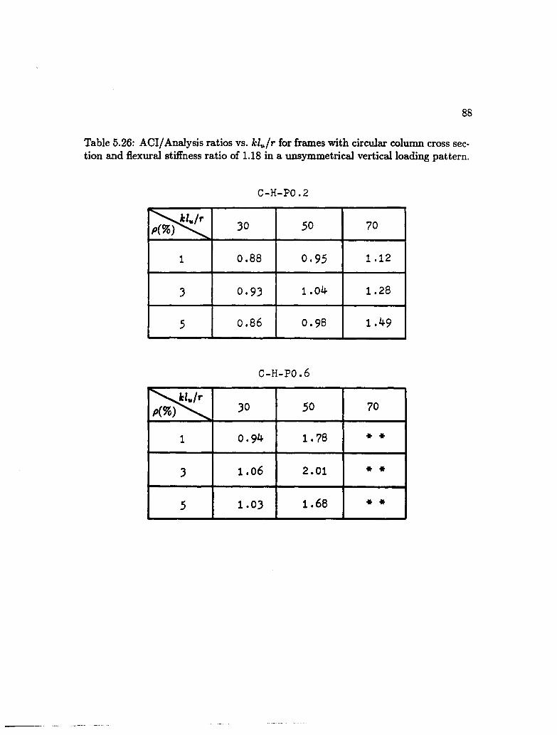
88
Table 5.26: ACI/Analysis ratios vs. k l u / r for frames with circular column cross section and flexural stiffness ratio of 1.18 in a unsymmetrical vertical loading pattern.
C-H-PO.2
30 50 70
1 0 .88 0 .95 1 .12
3 0 .93 1 .04 1 .28
5 0 .86 0 .98 1 .49
C-H-PO.6
\£l./r ^(*) \ 30 50 70
1 0 .94 1 .78 * *
3 1.06 2 .01 * *
5 1 .03 1 .68 * *

89
Table 5.27: ACI/Analysis ratios vs. k l u / r for frames with rectangular column cross section and flexural stiffness ratio of 0.23 in a unsymmetrical vertical loading pattern.
R-L-PO.2
30 50 70
1 0.76 0 .85 1 .05
3 0 .88 0 .94 1 .08
5 0 .90 0 .96 1 .07
R-L-PO.6
30 50 70
1 0.85 1 .44 * *
3 0.99 1 .28 3 .87
5 1 .00 1 .20 2 .34

90
Table 5.28: ACI/Analysis ratios vs. k l u / r for frames with rectangular column cross section and flexural stiffness ratio of 1.18 in a unsymmetrical vertical loading pattern.
R-H-PO.2
30 50 70
i 0 .82 0 .92 1 .16
3 0.88 1 .00 1 .33
5 0.85 0.96 1 .20
R-H-P0.6
30 50 70
1 0.90 1.68 * *
3 1 .09 2.03 * *
5 0.99 1 .65 * *

91
In Table 5.28 the results of frames having rectangular column cross section,
flexural stiffness ratio of 1.18, and P/P0 of 0.2 and 0.6 (R-H-P0.2, and R-H-P0.6, re
spectively) are presented. These cases have similar behavior with the previous cases
(Table 5.27). The ACI code method is unconservative for cases with slenderness
ratio of 30 with P/P0 = 0.2, and it is conservative for cases where the slenderness
ratio is 50 and 70 respectively for high level of axial load (P/P0 = 0.6).
5.2.4 Analysis according to the shape of column cross section:
Tables 5.29 to 5.34 show the ACI/Analysis ratio in relation to the shape
of the column cross section for a given percentage of steel. Tables 5.29, 5.30, and
5.31 contain the information of frames having low flexural stiffness ratio of 0.23 and
slenderness ratio of 30, 50, and 70 respectively. A close inspection of these tables
would show that in most cases the ACI/Analysis ratio tends to be higher for the
cases where circular columns cross sections were used; however, the difference from
these values to those of the cases with rectangular column cross sections are small in
most cases. Table 5.32, 5.33, and 5.34 show the information obtained from frames
having a flexural stiffness ratio of 1.18. Again, in most cases the ACI/Analysis
ratios are higher for cases when circular column cross sections were used. However
these values are not too far from those of cases having rectangular column cross
section.
5.2.5 Analysis according to the flexural stiffness ratio:
Tables 5.35 through 5.40 show the ACI/Analysis ratio rearranged accord
ing to the two values of flexural stiffness ratios used in the analysis. The results

obtained from frames having circular column cross sections and a slenderness ra
tio of 30, 50, and 70 are presented in Tables 5.35, 5.36, and 5.37, respectively. In
the same way, the results obtained from frames having rectangular column cross
sections and slenderness ratios of 30, 50, and 70 are shown in Tables 5.38, 5.39,
and 5.40, respectively. A close look at these tables would show that in most cases
the ACI/Analysis ratio is higher in the cases where a stiffness ratio of 1.18 were
used. This indicates that the ACI code method predicts more conservative values
when the flexural stiffness increases, this behavior is more noticible for cases where
slenderness ratios of 50 and 70 were used.

93
Table 5.29: ACI/Analysis ratios vs. shape of column cross section for frames with flexural stiffness ratio of 0.23 and k l j r of 30 in a unsymmetrical vertical loading
pattern. L-30-P0.2
^•^cross
p(%) c R
1 0 .79 0 .76
3 0 .91 0 .88
5 0 .95 0 .90
L--30-P0.6
C R
1 0.86 0 .85
3 1 .02 0 .99
5 1 .04 1 .00

94
Table 5.30: ACI/Analysis ratios vs. shape of column cross section for frames with fiexural stiffness ratio of 0.23 and k l u / r of 50 in a unsymmetrical vertical loading pattern.
L-50-P0.2
p(%) c R
1 0 .87 0 .85
3 1 .00 0 .94
5 1 .03 0 .96
L-50-P0.6
C R
1 1 .42 1 .44
3 1 .60 1 .28
5 1 .49 1 .20

95
Table 5.31: ACI/Analysis ratios vs. shape of column cross section for frames with flexural stiffness ratio of 0.23 and k l u / r of 70 in a unsymmetrical vertical loading pattern.
L-70-P0.2
^•^cross ,or\">^sectton
p(7o) c R
1 * 1.05
3 1 .19 1 .08
5 1 .19 1 .07
L--70-P0.6
p(^^ertion C R
1 * * * *
3 * * 3.87
5 * * 2.3^

96
Table 5.32: ACI/Analysis ratios vs. shape of column cross section for frames with flexural stiffness ratio of 1.18 and k l u / r of 30 in a unsymmetrical vertical loading pattern.
H-30-P0.2
/0T>>^aect»on p(%) C R
1 0 .88 0 .82
3 0 .93 0 .88
5 0 .86 0 .85
H-30-P0.6
C R
1 0 .9^ 0 .90
3 1 .06 1 .09
5 1 .03 0 .99

97
Table 5.33: ACI/Analysis ratios vs. shape of column cross section for frames with flexural stiffness ratio of 1.18 and k l u / r of 50 in a unsymmetrical vertical loading pattern.
H-50-P0.2
p{%) C R
1 0 .95 0 .92
3 1 .04 1 .00
5 0 .98 0 .96
H-50-P0.6
C R
1 1 .78 1 .68
3 2 .01 2 .03
5 1 .68 1 .65

98
Table 5.34: ACI/Analysis ratios vs. shape of column cross section for frames with flexural stiffness ratio of 1.18 and k l u / r of 70 in a unsymmetrical vertical loading pattern.
H-70-P0.2
p(%) c R
1 1 .12 1 .16
3 1 .28 1 .33
5 1.49 1 .20
H-70-P0.6
C R
1 * * * *
3 * * * *
5 # * * *

99
Table 5.35: ACI/Analysis ratios vs. flexural stiffness ratio for frames with circular column cross section and k l u / r of 30 in a unsynunetrical vertical loading pattern.
C-30-P0.2
Ae«m 0.23 1.18
I 0.?8 0.88
3 0.91 0.93
5 0.95 0.86
c : -3O-PO .6
0 .23 1.18
1 0.86 0.9^
3 1.02 1.06
5 1.04 1.03

100
Table 5.36: ACI/Analysis ratios vs. flexural stiffness ratio for frames with circular column cross section and k l u / r of 50 in a unsymmetrical vertical loading pattern.
C-50-P0.2
0.23 1 .18
1 0.8? 0 .95
3 1 .00 1 .04
5 1.03 0.98
c -50-P0.6
Amid
0 .23 1 .18
I 1 .42 1 .78
3 1 .60 2 .01
5 1 .49 1 .68

101
Table 5.37: ACI/Analysis ratios vs. flexural stiffness ratio for frames with circular column cross section and k l u / r of 70 in a unsymmetrical vertical loading pattern.
C-70-P0.2
0 .23 1 .18
i * 1.12
3 1 .19 1 .28
5 1 .19 1 .49
C -70-P0.6
0 .23 1 .18
1 * # « *
3 * * * *
5 # * * *

102
Table 5.38: ACI/Analysis ratios vs. flexural stiffness ratio for frames with rectangular column cross section and k l u / r of 30 in a unsymmetricaJ vertical loading pattern.
R-30-P0 .2
/team 0.23 . 1.18
1 0.76 0.82
3 0.88 0.88
5 0 .90 0 .85
J 1-30-P0.6
/Aeom 0.23 1.18
i 0 .85 0 .90
3 0 .99 1 .09
5 1 .0 0 0 .99

103
Table 5.39: ACI/Analysis ratios vs. flexural stiffness ratio for frames with rectangular column cross section and k l u / r of 50 in a unsymmetrical vertical loading pattern.
R-50-P0.2
C .23 1.18
I 0.85 0.92
3 0.9^ 1.00
5 0.96 0.96
R 1 0
1 O
CT
n
" S^EOL/ACOM 0.23 1.18
I l . k k 1.68
3 1.28 2.03
5 1.20 1.65

104
Table 5.40: ACI/Analysis ratios vs. flexural stiffness ratio for frames with rect-anguar column cross section and k l u / r of 70 in a unsymmetrical vertical loading pattern.
R-70-P0.2
0.23 1.18
I l .05 1.16
3 i—»
o
CD
1.33
5 1 .07 1 .20
R-70-P0.6
*NS^e«l/Aeam 0.23 1 .18
1 * * * *
3 3.87 * *
5 2.3^ * #

105
CHAPTER 6
Summary and Conclusions
This thesis has been developed with the purpose of analyzing the accuracy of
the Moment Magnifier Method of the American Concrete Institute Code (ACI 318-
83) as an approximate design method of reinforced concrete frames. The analysis
was carried out by developing a parametric study based on different combinations of
six main variables that, according to some previous studies, have a great influence in
the behavior of reinforced concrete frames. These variables are: axial load intensity,
P/P0; column reinforcement ratio, p\ slenderness ratio, klu/r; shape of column
cross section, flexural stiffness ratio, and the axial load distribution. A total of
216 different cases of single bay fixed-base portal frames were examined, using the
computer program FPIER (Poston et al., 1983), to obtain the analytical 'exact'
solution. A given set of vertical loads were applied to the columns of each frame in
one increment followed by an incrementally lateral load, until failure was reached.
The higher analytical moment at the four corners of each frame at failure was then
compared with the design moment predicted by the Moment Magnifier Method of
the American Concrete Institute Code (ACI 318-83).
The comparisons showed that certain aspects of the observed responses were
different for the symmetrical and unsymmetrical axial loading cases. However, the
following conclusions hold true for both symmetrical (axial loads applied to both

106
columns) and unsymmetrical (axial load applied to one column only) loaded frames.
The Moment Magnifier Method predicts a conservative design moment for the frame
when:
• the axial load increases;
• the slenderness ratio increases; and
• when circular column cross sections are used.
For the frames loaded symmetrically, the Moment Magnifier Method pre
dicts more conservative moments when a low percentage of steel is used. It is also
concluded that the Moment Magnifier Method predictions did not show a specific
trend of variation according to the flexural stiffness ratio.
For the frames loaded unsymmetrically, the Moment Magnifier Method pre
dictions are conservative for low level of axial loads and low slenderness ratios. The
Moment Magnifier Method did not show a specific behavior according to the per
centage of steel used in the columns; however, the predictions are conservative when
high flexural stiffness ratio is used.

APPENDIX A

108
PROGRAM FPIER
The program FPIER was written by Dr. Randall W. Poston, Dr. Manuel
Diaz, Dr. Jose M. Roesset, and Dr. John E. Breen, with research support from the
Texas Department of highway and Public Transportation to the Ferguson Structural
Engineering Laboratory at the University of Texas at Austin. The primary objective
of the program is the structural analysis of a reinforced concrete frame up to two
bays and three stories with symmetrical configuration. The listing of the program
is presented in the following pages.

C*F45V1P0* PROGRAM FPIER
c * « C * » PROGRAM FPIER « » C * • C • THE PRIMARY OBJECTIVE OF THE PROGRAM IS THE * C * STRUCTURAL ANALYSIS OF A REINFORCED CONCRETE C » FRAME UP TO TWO BAYS AND THREE STORIES (TAKING • C * INTO ACCOUNT SYMMETRY). IT COULD BE USED FOR • C » THE ANALYSIS OF A REINFORCED CONCRETE BEAM-COL C * UMN(ZERO BAY,ONE STORY) TOO. THE PROGRAM HAS * C • BEEN DEVELOPED FOR STATIC LOADING ONLY. * C * • c
CHARACTER*!,ASHTO(IO),IHOLL,IHOLLl,IH1,ITITLE(20),ITYPE(2), ISOLID,IOVAL,ICHOLL,INOl,IV1,ISOLI1,IOVAL1,ICHOL1, IMTYP(9,2),GREQ(27),IOR(3),INO,IH,IV,ICODE
DIMENSION AKFX(12),AKFY(12),AKFZ(12),AKX(12),AKY(12),AKZ(12), 1AMAT(3,3),AXF(150),BMAT(3,3,150),BW(2),CFA(4000),CONFX(4000), 2CONFZ(4000),DFORA(6,60),DFORB(6,60),DU(72),DUA(6),DUB(6), 3EPS(150),EZC(200),EZS(200),FIY(ISO),FIZ(150),FOR(6),FORA(6,60), 4FORB(6,60),FORM(66,15),H(3),HH(10,9),ICCON(9), 5INSECT(9),INSEG(9),ISEM(15),JR(12),NFC(10,9), 6NFS(10,9),NIC(10,9),NIS(10,9),NSEM(15),PDIS(72),PFOR(72), 7ROT(6,6),SA(6,6,60),SB(6,6,60),SC(6,6,60),SKAA(6,6,60), 8SKAB(6,6,60),SKBB(6,6,60),STAA(6,6),STAB(6,6),STBA(6,6),STBB(6,6), 9STK(72,72),STLA(20C0),STLX(2000},STLZ(2000),TKAA(6,6,15), •TKAB(6,6,15),TK33(6,6,15),U(72),UT(6,60),UU(6,60) DIMENSION GAMMA(10),BFAC(10,14) COMMON /ONE/ ZI,TF,XI,TW COMMON /TWO' CT30ID(5),TWALL(5),NW,NWX,NWY COMMON /THRE/ IOR,INO,IH,IV COMMON /FOUR/ STT(3),STS(3),GAMMAZ(3),GAMMAX(3),WLSTL(5),NRING COMMON /FIVE/ ISOLID,IHOLL,IOVAL,ICHOLL COMMON/LO/ SIG COMMON /LI/ CYL,RK,EC,ENO,EU COMMON /L2/ FY,EY,RATIO(10) COMMON /STF./ DA11, DA12 , DA13, DA21, DA22 ,DA2 3 , DA31 ,DA32 , DA33 COMMON /SUP/ IPRNT COMMON /SAME/ KCTYPE,KSTYPE.KFY,KWX,NX,NY,KV,KH,NZ COMMON/F1/ BIGC,MLOAD,MINC,MSEG,MSECT COMMON /Dl/ ASHTO COMMON /D2/ GAMMA,BFAC,IPRB COMMON/F2/ BIGS,JLOAD,JINC,JSEG,JSECT COMMON/DSING/CUMMF(66,15),CUMFF(72) DATA GREQ/'AASH','TO £','OUAT",'ION:',' G','AMMA','(BD*',
1 'D+BL' , ' * (L+ ', ' I )+B' , 'C*CF' , '+BE* 1 , 'E+BB' , 1 *B*B' , 2 'S*SF','+BW*1,'W+BW,'L«WL','+BL*','LF+B','R*(R', 3 '+S+T',1)+BE','O'EQ','*BIC','E*IC','E) '/
C INO,IH, ISOLID, IHOLL, IOVAL, IONE.IZERO, ARE PARAMETERS(VALUES AS C DEFINED) USED IN THE PROGRAM TO MAKE DECISIONS.
DATA INOl/'NO •/. IH1/' HORI */. IV1/'VERT'/, ISOLI1/1 SOLI'/, IHOLLl/'HOLL'/,IOVAL1/'OVAL'/,ICHOL1/'CIRH'/
DATA IONE/1/,IZERO/O/ C
OPEN(UNITS30,FILE3'LOU30.DAT',STATUS='OLD') OPEN(UNIT340, FILE*' LOU4 0. OUT', STATUS3' NEW' )
C IN0=IN01

IH=IH1 IV=IV1 ISOLID=ISOLI1 IHOLL=IHOLL1 I0VAL=I0VAL1 ICH0LL=ICH0L1 KCTYPE=0 KSTYPE=0
C READ PROBLEM TITLE AND ECHO PRINT IT READ (30,100G,END=10000)(ITITLE(I),I=1,20)
1000 FORMAT(BZ,20A4) 10000 WRITE(40,2000)(ITITLE(I)* 1 = 1 * 20)
2000 FORMAT)'1',4X,20A4) C READ AND ECHO PRINT NUMBER OF COLUMN LINES(NCOL) AND NUMBER OF C LEVELS(NLVL).
READ (30,1010,END=10001)NCOL,NLVL 1005 FORMAT(BZ,I10)
10001 WRITE(40,1007)NCOL,NLVL 1007 FORMAT<'0','NUMBER OF COLUMN LINES*•,12,/,
1' NUMBER OF LEVELS =',I2,/) 1010 FORMAT)BZ,3110)
C CALCULATE NUMBER OF BAYS (NBY) NBY=NCOL-l
C READ COLUMN HEIGTHS PER LEVEL (H(I)) READ (30,1020,END=10002)(H(I),1=1,NLVL)
1020 FORMAT(BZ,8F10.0) C IF NBY DIFFERENT THAN ZERO READ BEAM LENGTHS PER BAY(BW(I)). C IF NBY EQUAL ZERO MAKE THE PARAMETER NR EQUAL NBY. 10002 IF(NBY.EQ.O) GO TO 10
READ (30,1020,END= 1C)(BW(I),I=1,NBY) 10 NR=NBY
C EVALUATE NUMBER OF TOTAL JOINTS,NJT NJT=NCOL»(NLVL*l) NMEM=NLVL*(2«NCOL-l)
C READ AND ECHO PRINT THE NUMBER OF JOINTS WITH CONSTRAINT OR C SPECIFIED DISPLACEMENTS (NCJ),AND THE NUMBER OF JOINTS WITH C SPRINGS (NJSP).
READ (30,1010,END=10003)NCJ,NJSP 10003 WRITE(40,2001)NCJ,NJSP
2001 FORMAT(///,3X,'NUMBER OF JOINTS WITH CONSTRAINED',/, 1 3X,' OR SPECIFIED DISPLACEMENTS =',15,/, 2 3X,'NUMBER OF JOINTS WITH SPRINGS =',IS)
C INITIALIZE FOR EACH JOINT THE VECTORS OF ROTATIONAL SPRING C STIFFNESSES, THE VECTORS OF TRANSLATIONAL SPRING STIFF C NESSES, AND THE VECTOR OF JOINT RELEASE CODES OF NODAL C POINT I.
DO 13 1=1,NJT AKX(I)=0. AKY(I)=0. AKZ(I)=0. AKFX( I )=0. AKFY{I)=0. AKFZ(I)=0.
13 JR( I )-0 C IF NCJ DIFFERENT THAN ZERO READ AND ECHO PRINT THE JOINT C NUMBER,J, AND ITS RESPECTIVE VECTOR OF JOINT RELEASE CO C DES.JR(J), OTHERWISE GO TO CHECK IF THERE ARE JOINTS WITH C SPRINGS.
IF(NCJ.EQ.O) GO TO 15 WRITE(40,2002)

2002 FORMAT!///,3X,' JOINT NO.1,4X,'RELEASE CODE') DO 14 1=1,NCJ READ (30,1010,END= 14)J,JR(J)
14 WRITE(40,2003)J,JR(J) 2003 FORMAT(4X,I5,7X,I10)
C IF NJSP DIFFERENT THAN ZERO READ AND ECHO PRINT THE JOINT C NUMBER AND ITS RESPECTIVE VECTORS OF SPRING STIFFNESSES, C OTHERWISE GO TO READ MATERIAL PROPERTIES. C
15 IF(NJSP.EQ.D) GO TO 17 WRITE(40,2004)
2004 FORMAT (///, 16X, ' »»>TRANSLATIONAL SPRINGS «<«',5X, 1 • »»>ROTATIONAL SPRINGS <««',/, 3X, • JOINT NO. ' ,6X, ' X-DIR ' , 210X,'Y-DIR',10X,'Z-DIR',7X,'AROUND X-AXIS', 2X, ' AROUND '/-AXIS', 32X,'AROUND Z-AXIS')
DO 16 1=1,NJSP READ (30,1025,END= 16)J,AKX(J),AKY(J),AKZ(J),AKFX{J),
+AKFY(J),AKFZ(J) 16 WRITE(40,2005)J,AKX(J),AKY(J),AKZ(J),AKFX(J),AKFY(J),AKFZ(J)
2005 FORMAT(4X,I5,6X,3(E12.5,3X),2X,3(E12.5,3X)) 1025 FORMAT!BZ,119,7F10.0)
C READ AND ECHO PRINT MATERIAL PROPERTIES 17 READ (30,1020,END=10004)CYL,FY,RK,EC,EY,EU,BETA
C EVALUATE ENO THE STRAIN CORRESPONDING TO RK*CYL(REDUCE ... C CONCRETE STRENGTH) 10004 ENO=(1.0+BETA)*RK*2.0*CYL/EC
IF(EU.EQ.0.) EU=1.9*ENO IF(EU.LE.ENO) WRITE(40,81C3) IF(EU.LE.ENO) STOP 8200
8100 FORMAT('0',3X,42HULTIMATE STRAIN IS NOT GREATER THAN STRAIN ,18H AT MAXIMUM STRESS)
WRITE( 40 , 2C 36 ) CYL, FY, RK , EC, EY, E'J, BETA 2006 FORMAT!///,3X,'CONCRETE STRENGTH
1 3X,'STEEL YIELD POINT 2 3X,'STRENGTH REDUCTION FACTOR 3 3X,'CONCRETE MODULUS 4 3X,'STEEL MODULUS 5 3X,'CONCRETE ULTIMATE STRAIN 6 3X,'CREEP FACTOR
C C C FROM HERE THROUGH JUST BEFORE SENTENCE »130 THE CHARACTERISTICS C OF EACH MEMBER ARE EVALUATED ( NUMBER OF SEGMENTS, NUMBER OF C DIFFERENT SECTIONS,TYPE OF SECTION, NUMBER OF TOTAL CONCRETE FI C BERS, NUMBER OF TOTAL STEEL FIBERS, MOMENTS OF INERTIA. C C C IN = MEMBER NUMBER C MARY = THIS PARAMETER ALLOWS TO DIFFERENTIATE BETWEEN C COLUMNS(MARY=1), AND BEAMS(MARY=2). C NCFS = STORES TOTAL NUMBER OF CONCRETE FIBERS. C NSFS = STORES TOTAL NUMBER OF STEEL FIBERS. C I = CONTROLS COLUMN LINE NUMBER(LOOP OVER BAYS) C J = CONTROLS LEVEL NUMBER(LOOP OVER FLOORS). C NR = CONTROLS THE NUMBER OF COLUMNS TO BE PROCESSED C TAKING INTO ACCOUNT SYMMETRY. C C
IF(NR.EQ.O) NR=1 IN=0
,F10.2,/, ,F10.2,/, ,F10.2,/ , ,E12.4,/, ,E12.4,/, , E12 . 4 , /, ,F10.2)

MARY=1 NCFS=1 NSFS=1 1 = 1
20 J = 1 30 IN=IN+1
C C READ NUMBER OF SEGMENTS,INSEG(IN), AND NUMBER OF DIFFERENT C SECTIONS,INSECT(IN),OF MEMBER IN. STORE THE VALUES IN NSEG C AND NSECT RESPECTIVELY. ECHO PRINT. C
READ (30,1010,END=I0005)INSEG(IN),INSECT)IN) IF(INSECT(IN).EQ.0) INSECT(IN)=1
10005 NSEG=INSEG(IN) NSECT=INSECT(IN) WRITE(40,2010)1,J,NSEG,NSECT
2010 FORMAT(///,3X,'MEMBER',2X,12,' LEVEL',2X,12, 1 ' HAS ',2X,12,' SEGMENTS AND ',2X,I2, 2 ' DIFFERENT SECTIONS ',/)
C C IF NSEG = 1 OR 0 THE LENGTH OF THE MEMBER EQUAL THE MEMBER C LENGTH. OTHERWISE READ AND ECHO PRINT SEGMENT LENGTHS,HH. C
IF(NSEG.LE.l) GO TO -10 READ (30,1026,END=10006)<HH(L,IN),L=1,NSEG)
1026 FORMAT(BZ.15F5.0) 10006 WRITE!40,2020)(HH(L,IN),L=1,NSEG)
2020 FORMAT(/,3X,'SEGMENT LENGTHS',10F1D.2,//) C C READ SECTION TYPE,THE CONCRETE STATE CODE,STEEL FIBERS CODE C GENERATION, AND THE PRINTER OPTION. C
40 IF(NSEG.LE.l) HH(1,IN)=H(IN) READ (30,1030,END=10007)ITYPE,ICON,ISTAT,IPRNT
1030 FORMAT(BZ,2A4,2X,3110) 10007 ICCON(IN)=ICON
DO 45 IT=1,2 45 IMTYP(IN,IT)=ITYPE(IT)
WRITE(40,2030)ITYPE 2030 FORMAT(///,3X,'THE MEMBER CROSS-SECTION IS',2X,2A4,/)
C C IF ICON = 0 CONCRETE IS CONSIDERED UNCONFINED, IF ICON = 1 C CONCRETE IS CONSIDERED CONFINED. C
IF(ICON.EQ.O) WRITE!40,2040) IF(ICON.EQ.l) WRITE!40,2050)
2040 FORMAT!'0',2X,'CONCRETE FIBERS WILL BE MODELLED AS', 1' UNCONFINED CONCRETE')
20S0 FORMAT!'0',2X,'CONCRETE FIBERS WILL BE MODELLED AS', 1* CONFINED CONCRETE')
C C IF ISTAT = 0 THE PROGRAM WILL GENERATED STEEL FIBERS, C IF ISTAT = 1 THE USER WILL READ IN INDIVIDUAL REINFORCEMENT. C
IF (ISTAT.EQ.IZERO) WRITE!40,2060) IF(ISTAT.EQ.IONE) WRITE(40,2070)
2060 FORMAT!'0',2X,'STEEL FIBERS ARE GENERATED BY THE PROGRAM') 2070 FORMAT!'0',2X,'STEEL FIBERS ARE READ IN BY THE USER')
C C IF IPRNT = 0 PRINT OUT OF FIBER PROPERTIES WILL BE SUPRESSED

c IF(IPRNT.EQ.IZERO) WRITE!40,2080)
2080 FORMAT!'0',2X,'PRINT OUT OF FIBER PROPERTIES', 1' HILL BE SUPPRESSED')
C C LOOP IN SECTIONS TO FIND THEIR PROPERTIES(TYPE,STEEL C FIBERS,CONCRETE FIBERS.MOMENTS OF INERTIA,AREA) C
DO 120 JAY=1,NSECT C READ FIRST!II) AND LAST(I2) SEGMENTS WITH EQUAL SECTION
READ (30,1010,END=10008)II,12 10008 WRITE!40,2090)JAY
2090 FORMAT!'0',2X,'CROSS-SECTION TYPE',13) C READ SECTION DIMENSIONS AS INDICATED BY ITYPE (SOLID,OVAL, C HOLLOW)
IF (ITYPE (1) .EQ. I SOLID) GO TO 50 IF!ITYPE!1).EQ.IOVAL) GO TO 50 IF(ITYPE(1).EQ.IHOLL) GO TO 60 IF(ITYPE(1).EQ.ICHOLL) GO TO 65 WRITE(40,2100)
2100 FORMAT)'0',2X,'MISTAKE MADE IN INPUT OF SECTION TYPE') 50 READ (30,1320,END=10009)ZI,XI
10009 WRITE(40,2U0)ZI,XI 2110 FORMAT!BZ,'0',2X,'Z-DIMENSION =',F10.2,/,
1 3X,'X-DIMENSION =',F10.2) GO TO 75
60 READ (30,1020,END=10010)ZI,TF,XI,TW 10010 WRITE(40,2120)ZI,TF,XI,TW
2120 FORMAT!'0',2X,'Z-DIMENSION=',F10.2,/, 1 3X,'FLANGE THICKNESS-',F10.2,/, 2 3X,'X-DIMENSION=',F10.2,/, 3 3X,'WEB THICKNESS =',F10.2) READ 130,1030,END=100U) ICODE
C IF ICODE IS NOT EQUAL TO NO READ ORIENTATION AND NUMBER C OF INTERIOR WALLS. 10011 IF(ICODE.EQ.INO) GO TO 75
READ (30,1035,END=10012)IOR,NW 1035 FORMAT (BZ, 3A4,8X, 110)
10012 READ (30,1020,END=10013)(CTROID(L),TWALL(L),L=1,NW) 10013 WRITE(40,2130)NW,IOR
2130 FORMAT!///,3X,'NUMBER OF INNER WALLS=',15,/, 1 3X,'WALLS ARE ORIENTED'.2X.3A4)
WRITE!40,2140) 2140 FORMAT!//,3X,'NO.',5X,'Z OR X CENTROID',4X,'THICKNESS')
DO 70 L=1,NW 70 WRITE!40,2150)L,CTROID(L),TWALL(L)
2150 FORMAT!1X,I5,5X,F10.2,6X,F10.2) GO TO 75
65 READ (30,2110,END=10014)ZI,TF 10014 WRITE!40,2125)ZI,TF
2125 FORMAT! '0' ,2X, 'DIAMETER OF SECTION*',F10.2,/, 1 3X,'WALL THICKNESS =',F10.2)
75 CONTINUE C EVALUATE THE NUMBER OF CONCRETE FIBERS AND THEIR PROPERTIES C ACCORDINGLY TO ITYPE!1).
IF( ITYPE! 1) .EQ. ISOLID) CALL SOLSCR(CONFZ (NCFS),CONFX(NCFS) 1,CFA(NCFS),NFIB) IF(ITYPE(l).EQ.IHOLL) CALL DSCRIB(CONFZ(NCFS) ,CONFX(NCFS),
lCFA(NCFS),ICODE,NFIB) IF(ITYPE(1) .EQ.IOVAL) CALL OSCRIB(CONFZ(NCFS) .CONFX(NCFS),
lCFA(NCFS),NFIB) IF(ITYPE(1).EQ.ICHOLL) CALL CIRSCR(CONF2(NCFS),CONFX(NCFS),
1 CFA(NCFS),NFIB) C STORE THE INITIAL,NIC(L,IN),AND THE FINAL,NFC(L,IN) C CONCRETE FIBER OF SEGMENT L MEMBER IN.
DO 80 L=I1,12 NIC(L,IN)=NCFS
80 NFC(L,IN)-NFIB C EVALUATE THE TOTAL NUMBER OF CONCRETE FIBERS,NCFS. C IF NCFS GREATER THAN 4000 PRINT ERROR MESSAGE.
NCFS=NCFS+NFIB IF(NCFS.GT.4000) GO TO 962
C FROM HERE TROUGH SENTENCE 85 THE PROGRAM EVALUATES THE C MOMENT OF INERTIA OF THE CONCRETE SECTION ARROUND THE C Z-AXIS AND THE X-AXIS. C KAY = CONTROLS LOOP OVER NUMBER OF FIBERS. C KK = FIBER NUMBER. C XC = STORES X-CENTROID OF CONCRETE FIBER KK. C ZC = STORES Z-CENTROID OF CONCRETE FIBER KK. C AR = STORES AREA OF CONCRETE FIBER KK. C
ZIZ=0. XIX=0. DO 85 KAY = 1,NFI3 KK=NIC(II,IN)+KAY-1 XC=CONFX(KK) ZC=CONFZ(KK) AR=CFA(KK) ZIZ=ZIZ+XC*XC*AR
85 XIX=XIX+ZC*ZC*AR WRITE(40,2I60)ZIZ,XIX
2160 FORMAT!'0',2X,'MOMENT OF INERTIA ABOUT Z-AXIS=',E10.3,/, 1 3X,'MOMENT OF INERTIA ABOUT X-AXIS=',E10.3,/)
C IF ISTAT = 0 READ THE NUMBER OF STEEL RINGS,NRING. ALSO READ C THE STEEL END AREA,STT( L) , THE SIDE STEEL AREA,STS(L), THE C Z-COVER,GAMMAZ(L), THE X-COVER,GAMMAX(L) FOR EACH RING. IF I C TYPE EQUAL HOLLOW AND ICODE EQUAL YES, READ IN ADDITION THE C STEEL AREA OF INTERIOR WALLS. C C IF ISTAT = 1 CALL SUBROUTINE REDE AND READ IN STEEL FIBERS.
IF(ISTAT.EQ.IZERO) GO TO 90 IF(ISTAT.EQ.IONE) GO TO 102
90 READ (30,1025,END=10015)NRING,(STT(L),STS(L),L=1,NRING) 10015 WRITE(40,2170)NRING
2170 FORMAT(///,3X,'NUMBER OF STEEL RINGS=',15,/, 1 3X,'NO.',5X,'AREA OF END STEEL',5X, 2 'AREA OF SIDE STEEL')
WRITE) 40,2180)(L,STT(L),STS(L),L-1,NRING) 2180 FORMAT(IX,13,7X.F10.2,14X,F10.2)
READ (30,1020,END=10016 ) (GAMMAZ(L),GAMMAX(L) ,L=1,NRING) 10016 WRITE(40,2190)
2190 FORMAT!//,3X,"N0.',6X,'Z COVER',5X,'X COVER') WRITE< 40,2200)(K, GAMMAZ (K), GAMMAX (K), K = 1, NRING)
2200 roRMAT(lX,X3,5X,F10.2,2X,F10.2) IF(ITYPE(l).EQ.IHOLL. AND. ICODE. NE.INO) GO TO 95 GO TO 100
95 READ (30,1020,END*10017)(WLSTL(L),Lsl,NW) 10017 WRITE(40,2210)
2210 FORMAT(1X,I3,12X,F10.2) 100 CONTINUE

C EVALUATE THE NUMBER OF STEEL FIBERS AND THEIR PROPERTIES C ACCORDINGLY TO ITYPE(SOLID,HOLLOW,OVAL).
IF(ITYPE(1).EQ.ISOLID) CALL SSCRIB(STLZ(NSFS).STLX(NSFS), 1STLA(NSFS),ICODE,NSTOT,ITYPE(1)) IF(ITYPE(1).EQ.IHOLL) CALL SSCRIB(STLZ(NSFS).STLX(NSFS),
1STLA(NSFS),ICODE,NSTOT,ITYPE(1)) IF(ITYPE(l).EQ.IOVAL) CALL OSSTL(STLZ(NSFS),STLX(NSFS),
lSTLA(NSFS),NSTOT) IF(ITYPE(l).EQ.ICHOLL) CALL CIRSTL(STLZ(NSFS),STLX(NSFS),
1 STL A (NSFS), NSTOT) GO TO 105
C SUBROUTINE REDE IS USED TO READ IN STEEL FIBERS BY THE USER . . . 102 CALL REDE(STLZ(NSFS),STLX(NSFS).STLA(NSFS),NSTOT)
C LOOP IN SEGMENTS OF EQUAL SECTION TO STORE THE INITIAL,NIS(L,IN C AND THE FINAL,NFS(L,IN) STEEL FIBER OF SEGMENT L MEMBER IN.
105 DOllO L=I1,I2 NIS(L,IN)=NSFS
110 NFS(L,IN) =NSTOT C EVALUATE TOTAL NUMBER OF STEEL FIBERS,NSFS. IF NSFS GREATER C THAN 2000 PRINT ERROR MESSAGE.
NSFS=NSFS+NSTOT IF(NSFS.GT.2000) GO TO 961
120 CONTINUE KCTYPE=0 KSTYPE=0
C TORSIONAL PARAMETERS TO BE USED IN EVALUATING C THE TORSIONAL STIFFNESS
IF(ITYPE(1).NE.IOVAL) GO TO 122 XI2=XI*XI ZI2=ZI*ZI CNOT=XI2*ZI2/(XI2+ZI2) CJ2=-2.0«CNOT/ZI2 CJl=-2.0*CNOT/XI2 CJT=CJ1-CJ2 GO TO 124
122 IF(XI.GE.ZI) RRA=ZI/XI IF(XI.LT.ZI) RRA=XI/ZI CJT=4.0*RRA-3.36 *RRA*RRA+0.2 773 3 3*RRA*RRA*RRA-4.0/(3.0*RRA)
C END OF LOOP OVER SECTIONS C INCREASE J TO EVALUATE THE NEXT COLUMN. IF J LESS OR C EQUAL THAN NLVL REPEAT THE PROCEDURE FROM SENTENCE 30 C TO SENTENCE 120. OTHERWISE CHECK MARY.
124 J=J+1 IF(J.LE.NLVL)GO TO 30
C IF MARY =1 INCREASE THE NUMBER OF COLUMN LINE,I. OTHERWISE C GO OUT OF THE LOOP (SENTENCE 130)
GO TO(125,130),MARY C CALL GOTOER
125 1=1+1 C .... IF I LESS OR EQUAL THAN NR REPEAT THE PROCEDURE FROM SENTENCE C 20 TROUGH SENTENCE 125 TO PROCESS THE REMAINING COLUMNS. OTHER C CHECK NBY.
IF(I.LE.NR) GO TO 20 C IF NBY DIFFERENT THAN ZERO MAKE MARY=2, AND BEGIN TO PROCESS C THE GEOMETRIC PROPERTIES OF THE BEAMS. OTHERWISE GO TO 130 C (OUT OF THE LOOP)
IF(NBY.EQ.O) GO TO 130 MARY=2 GO TO 20

C DETERMINE THE MAXIMUN NUMBER OF SECTIONS PER SEGMENT, MNSSG, FOR C WHICH THE NUMBER OF MEMBERS, NMEM, THE NUMBER OF COLUMNS, NCM C AND THE NUMBER OF TOTAL SEGMENTS, NTSG ARE FIRST EVALUATED.
130 NMEM=(NCOL+NBY)*NLVL INM-IN NCM=NLVL*NBY NTSG=0 1 = 1
140 NTSG=NTSG+INSEG(I) IF(I.LE.NLVL.AND.NBY.GT.0) NTSG=NTSG+INSEG(I) IF(I.GT.NCM.AND.NBY.EQ.2) NTSG=NTSG *INSEG(I) 1 = 1 + 1
IF(I.LE.INM) GO TO 140 MNSSG=150/NTSG LGP=0 READ (30,1005,END=10018)NLFDG
10018 IF(NLFDG.GT.O) ILF=1 IF(NLFDG.LE.O) ILF=0
C LOOP OVER MEMBERS TO FIND STIFFNESS MATRICES PER SEGMENT 142 NCLR=NTSG+NMEM
ISEM(1)=1 MARY=1 11 = 0
NR=NBY NR1=NR+1 IF(NR.EQ.O) NR=1 IN=0
145 1=1 150 J=1 155 IN=IN+1
SIG=1.0 11 = 1 IF(II.GT.NR) 11=1 IF(MARY.EQ.l) IM=(II-l)*NLVL+J IF(MARY.EQ.2) IM=NR*NLVL+J IF(MARY.EO.1.AND.IM.NE.IN) SIG=-1.0 NSEG=1NSEG(IM) NSEM(IN)-NSEG*MNSSG IF(IN.LT.NMEM) ISEM(IN+1)=ISEM(IN)+NSEM(IN)
C LOOP OVER SEGMENTS TO RECALL NFIB,NSTOT,NSFS,NCFS C AND DEFINE THE PARAMETER RATIO EQUAL C STEEL AREA OVER CONCRETE AREA
DO 170 LL=1,NSEG L=LL IF(MARY.EQ.2.AND.I.EQ.2) L=NSEG-LL+1 AST=0. AG=0. NFIB=NFC(L,IM) NSTOT=NFS(L,IM) NSFS=NIS(L,IM)-1 NCFS=NIC(L,IM)*1 DO 160 K=1,NFIB
160 AG*AG+CFA(NCFS+K) DO 165 K=l,NSTOT
165 ASTsAST+STLA(NSFS+K) RATIO(L)=AST/AG
170 CONTINUE C END OF LOOP OVER SEGMENTS
NJ=NSEG*1 C INITIALIZE THE CONCRETE STRAIN,EZC, AND THE STEEL

C STRAIN,EZS,IN EACH FIBER DO 190 L=1,NFIB
190 EZC(L)=0. DO 200 L=l,NSTOT
200 EZS(L)=0. ICON=ICCON(IM) JJ=ISEM(IN)-1
C LOOP OVER SEGMENTS DO 220 LL=1,NSEG L=LL IF(MARY.EQ.2.AND.I.EQ.2) L=NSEG-LL+1 NSFS=NIS(L,IM) NCFS=NIC(L,IM) CALL CMSTF(CONFZ(NCFS),CONFX(NCFS),CFA(NCFS),STLZ(NSFS),
1 STLX(NSFS),STLA(NSFS),EZC,EZS,NFIB,NSTOT,L,ICON) NSCT-NSEM(IM)
C ASSEMBLE STIFFNESS MATRIX OF EACH SEGMENT DO 210 K=l fMNSSG JJ=JJ+1 BMAT(1,1,JJ)=DA11 BMAT(1,2,JJ)=DA12 BMAT(1,3,JJ)=-DA13 BMAT(2,1,JJ)=DA21 BMAT(2,2,JJ)=DA22 BMAT(2,3,JJ)=-DA23 BMAT(3,1,JJ)=-DA31 BMAT(3,2,JJ)=-DA32 BMAT(3 » 3 f JJ)=DA3 3 IF(MARY.EQ.l) GO TO 210 BMAT(1,2,JJ)=-BMAT(1,2,JJ) BMAT(2,1.JJ)=-BMAT(2,1,JJ) BMAT(1,3 rJJ)=-BMAT(1,3,JJ) BMAT(3,1,JJ)=-BMAT(3,1,JJ)
C APPLY FORWARD PASS TO BMAT AND STORE RESULTS IN BMAT ... 210 CALL PSINV(BMAT(1,1,JJ),3,3) 220 CONTINUE
J=J+1 IF(J.LE.NLVL) GO TO 155 1 = 1 + 1
IF(I.LE.NRl) GO TO 150 IF(NBY.EQ.O) GO TO 230 IF(MARY.EQ.2) GO TO 230 MARY=2 NR1=NR1-1 GO TO 145
230 DO 235 L=l,6 DO 235 K=1,NCLR UU(L,K)=0.
235 UT(L,K)=0. DO 240 1=1,150 AXF(I)=0. EPS(I)=0. FIY(I)=0.
240 FIZ(I)s0. DO 250 J=l,60 DO 250 1=1,6 FORA( I, J)=0. FORB(I,J)s0. DFORA(I,J)=0.
250 DFORB(I,J)=0.

NDF=6»NJT IF(NLFDG.GT.O) CALL DSIN(NLFDG,ILF,NDF,NLOAD,KPRNT,LGP,NMEM) IF(NLFDG.LE.O) READ (30,1005,END=10019)NLOAD
10019 IF(NLFDG.GT.O) WRITE(40,2700)ASHTO(LGP),<GREQ(I),1=1,27), . GAMMA (LGP >,BFAC( LGP, IPRB), (BFAC( LGP, I), 1 = 3, 4), . (BFAC(LGP,I),I=6,14)
WRITE!40,2230) NLOAD 2230 FORMAT!///,3X,'NUMBER OF LOAD CASES=',I3)
BIGC=1000. BIGS=-1000 DO 950 JAY=1,NLOAD WRITE(40,2235)JAY
2235 FORMAT!* 1•,15(/),20X,' *** LOAD CASE ',15,' ***') DO 260 1=1,66 DO 260 J=1,NMEM
260 FORM!I»J)=0. DO 270 1=1,NDF PFOR(I)=0.
270 PDIS(I)=0. IF(NLFDG.GT.O) GO TO 332 READ (30,1010,END=10020)NLINC,NML,KPRNT
10020 IF(KPRNT.EQ.O) KPRNT=1 WRITE!40,2240)NLINC,NML,KPRNT
2240 FORMAT!///, 3X,'NUMBER OF LOAD INCREMENTS11' ,15,/, 1 3X,'NUMBER OF MEMBERS LOADED =',15,/, 2 3X,'PRINTING INDEX =',I5) IF(NML.EO.O) GO TO 300 DO 290 NMJ=1,NML READ (30,1010,END=;D021)I,NMJL
10021 WRITE(40,2250)1 DO 290 NJL=1,NMJL READ (30,1040,END=13022)J,(FOR(L),L=1,6)
1040 FORMAT(BZ,I10,6F10.0) 2250 FORMAT(///,4X,' LOADED NO.',12,/,4X,' JOINT NO.',
14X,'FORCE-X',4X,'FORCE-Y'.4X,'FORCE-Z',4X,'MOMENT-X' ,4X, 2'MOMENT-Y',4X,'MOMENT-Z')
10022 WRITE!40,2255)J,(FOR(L),L=1,6) 2255 FORMAT!8X,I5,4X,3(1X,E10.3),3(2X,E10.3))
J1=6»(J-1) DO 280 L=1,6
280 FORM!Jl^L,I)=FOR(L) 290 CONTINUE 300 READ (30,1005,END=10023)NFJL
10023 WRITE!40,2270)NFJL 2270 FORMAT!///,3X,'NUMBER OF FRAME JOINTS LOADED=',I5)
IF(NFJL.EO.O) GO TO 342 WRITE!40,2280)
2280 FORMAT!///,4X,'JOINT NO.',4X,'FORCE-X',4X,'FORCE-Y',4X,'FORCE-Z', 14X, 'MOMENT-X',4X, 'MOMENT-Y' ,4X, 'MOMENT-Z' )
DO 330 I=1,NFJL READ (30,1040,END=10024)J,(FOR!L),L=1,6)
10024 WRITE!40,2290)J,(FOR(L),L=1,6) 2290 FORMAT!4X,I5,4X,3(1X,E10.3),3(2X,E10.3))
JJ«6*(J-1) JMASK=1000000 KSJR(J) DO 330 L=l,6 JJ=JJ+1 JMASK=JMASK/10 K=K-JMASK

IF(K) 310,320,320 310 PFOR{J J)=FOR(L)
K=K+JMASK GO TO 330
320 PDIS(JJ)=FOR(L) 330 CONTINUE
GO TO 342 C FORCES FROM LOADING GROUPS
332 DO 333 IJ=1,NDF PFOR(IJ)=CUMFF{IJJ IF(JAY.EQ.2) PFOR(IJ)=5.0*CUMFF(IJ)/12.0
333 CONTINUE DO 334 IJ=1,66 DO 334 IK=1,NMEM FORM(IJ,IK)=CUMMF(IJ,IK)
334 IF(JAY.EQ.2) FORM(IJ,IK)=5.0*CUMMF(IJ,IK)/12.0 NLINC=50-10*JAY IF(JAY.EQ.1) NLINC=50 WRITE(40,2720) IN=0 HARY=1 NR=NBY NR1=NR+1 IF(NR.EO.O) NR=1
335 1=1 336 J=1 337 IN=IN+1
11 = I IF(II.GT.NR) 11=1 IF(MARY.EQ.l) IM=(II-l)*NLVL+J IF(MARY.EQ.2) IM=NR*NLVL+J NSEG=INSEG(IM) NMJ=NSEG+1 WRITE(40,2730JIN WRITE(40,2740) DO 338 IJ=1,NMJ L2=6*IJ Ll=L2-5
338 WRITE(40,2290)IJ,(FORM)K,IN),K=L1,L2) J=J+1 IF(J.LE.NLVL) GO TO 337 1 = 1 + 1
IF(I.LE.NRl) GO TO 336 IF(NBY.EQ.O) GO TO 339 IF(MARY.EQ.2) GO TO 339 MARY=2 NR1=NR1-1 GO TO 335
339 HRITE(40,2750) WRITE(40,2740) DO 341 IJ=1,NJT L2*6»IJ Ll=L2-5
341 WRITE(40,2290)IJ,(PFOR(JI),JI=L1,L2) C LOOP ON LOAD INCREMENTS
342 DO 945 IL=1,NLINC NDF=6*NJT DO 345 1=1,NDF DO 345 J=1,NDF
345 STK(I,J)=0.

DO 348 1=1,NDF 348 DU(I)-PFOR(I)
IN=0 MARY=1 NR=NBY ISG=0 NR1=NR+1 IF(NR.EQ.O) NR = 1
350 1=1 360 J=1 370 IN=IN+1
11 = 1 SIG=1.0 IF(II.GT.NR) 11=1 IF(MARY.EQ.l) IM=(II-1)*NLVL+J IF(MARY.EQ.2) IM=NR*NLVL+J IFfMARY.EQ.1.AND.IM.NE.IN) SIG=-1.0 NSEG=INSEG(IM) NSEC=NSEM(IM) ICON=ICCON(IM) ITYPEf1)=IMTYP(IM,1) JJ=ISEM(IN)-1 DO 580 ME=1,NSEG ISEG=ME IF(MARY.EQ.2.AND.I.EQ.2) ISEG=NSEG+1-ME ISG=ISG+1 DO 380 L=l,6 DO 380 K=l,6
380 STBB(L,K)=0. STFJ1=0. DO 430 ISECT=1,MNSSG FOR (1) =DFORB (1,1 SG) JJ=JJ+1 AI=ISECT-1 AJ=MNSSG-1 AI=AI/AJ DAL=HH(ISEG,IM) DZ=DAL/AJ DIS=DAL*(1.-AI) FOR (2 ) =DFORB (5,ISG)-DIS• DFORB ( 3,1 SG) FOR(3)=DFORB(6,ISG)+DIS*DFORB(2,ISG) CALL PSMULT(BMAT(l,l,JJ),FOR,3,3,3,l) EPS(JJ)=EPS(JJJ+FOR(1) FIY(JJ)=FIY(JJ)+FOR(2) FIZ(JJ)=FIZ(JJ)+FOR(3) NFIB=NFC(ISEG,IM) NSTOT=NFS (ISEG, IM) NSFS=NIS(ISEG,IM)-1 NCFS"=NIC(ISEG,IM)-1 DO 390 L=1,NFIB IF(MARY.EQ.l) EZC(L)=EPS{J J)+CONFX(NCFS+L)*FIY(JJ)
1COHFZ(NCFS+L)*FIZ(JJ) IF(MARY.EQ.2) EZC(L)=EPS(JJ)-CONFX(NCFS+L)«FIY(JJ)
1CONFZ(NCFS+L)*FIZ(JJ) IF(EZC(L).LT.-EU) GO TO 964 IF(EZC(L).GE.BIGC) GO TO 390 MLOAD'JAY MINC=IL MSEG=ISEG MSECT=ISECT

BIGC=EZC(L) IHEM=IN
390 CONTINUE DO 395 L=l,NSTOT IF(MARY.EQ. 1) EZS(L) =EPS(JJ) +STLX(NSFS-X)«FIY(JJ)*SIG-
1STLZ(NSFS+L)*FIZ( JJ) IF(MARY.EQ.2) EZS(L)=EPS(JJ)-STLX(NSFS+L)«FIY(JJ)+
1STLZ(NSFS+L)*FIZ(JJ) IF(EZS(L).GT.0.01) GO TO 963 IF(EZS(L).LE.BIGS) GO TO 395 JLOAD =JAY JINC=IL JSEG=ISEG JSECT=ISECT BIGS=EZS(L) JMEM=IN
395 CONTINUE AG=0. AST=0. DO 400 K=1,NFIB
400 AG=AG+CFA(NCFS+K) DO 405 K=l,NSTOT
405 AST=AST+STLA(NSFS+K) RATIO(ISEG)=AST/AG NSF5=NIS(ISEG,IM) NCFS=NIC(ISEG,IM) CALL CMSTF(CONFZ(NCFS),CONFX(NCFS),CFA(NCFS),STLZ(NSFS),
1STLX(NSFS), STLA (NSFS),EZC,EZS,NFIB, NSTOT, ISEG, ICON) BMAT(1,1,JJ)= DA11 BMAT(1,2,JJ) = DAI2 BMAT(1,3,JJ)=-DA13 BMAT(2,1,JJ)= DA21 BMAT(2,2,JJ)= DA22 BMAT(2,3,JJ)=-DA23 BMAT(3,1,JJ)=-DA31 BMAT(3,2,JJ)=-DA32 BMAT(3,3,JJ)= DA33 IF(MARY.EQ.l) GO TO 408 BMAT(1,2,JJ)=-BMAT(1,2,JJ) BMAT(2,1,JJ)=-BMAT(2,1,JJ) BMAT(1,3,JJ)=-BMAT(1,3,JJ) BMAT(3,1,JJ) = -BMAT(3,1,JJ)
408 STFJ1=STFJ1+(DA22+DA33-DA32*CJT)*0.4 CALL PSINV(BMAT(1,1,JJ),3,3) DO 415 L=l,3 DO 410 K=1,3
410 AMAT(L,K)=0. 415 AMAT(L,L)-1.
CALL PSMULT(BMAT( 1,1, JJ), AMAT, 3,3,3,3) C*l. IF( ISECT.EO. l .OR. ISECT.EQ.MNSSG) C=0'.5 IF(MARY.E0.2) GO TO 420 STBB( 2,2) *STBB( 2,2 )+C*DZ«AMAT( 1,1) STBB<2,3)*STBB(2,3)+C*DZ*DIS*AMAT(1,3) STBB(1,2)sSTBB(1,2)-C*DZ*DIS*AMAT(1,2) STBB(2,6)*STBB(2,6)+C*DZ* AMAT (1,2) STBB(2,4)=STBB(2,4)+C»DZ«AMAT(1,3) STBB(3,3)«STBB(3,3)+C*DZ«DIS*DIS*AMAT(3,3) STBB( 1,3)=STBB(1,3)-C*DZ*DIS*DIS*AMAT(3,2) STBB(3,6)-STBB(3,6)+C*DZ*DIS*AMAT(3,2)

STBB(3,4)=STBB(3,4)+C*DZ*DIS«AMAT(3,3) STBB(1,1)=STBB(1,1)+C*DZ«DIS*DIS*AMAT(2,2) STBB(1,6)sSTBB(1,6) -C*DZ*DIS*AMAT(2,2) STBB( 1,4)=STBB(1,4)-C*DZ*DIS*AMAT(2,3) STBB(6,6)=STBB(6,6)+C*DZ*AMAT(2,2) STBB(4,6)=STBB(4,6)+C*DZ*AMAT(2,3) STBB(4,4)=STBB(4,4)+C*DZ*AMAT(3,3) GO TO 430
420 STBB(1,1)=STBB(1,1)+C*DZ*AMAT(1,1) STBB(1,2)=STBB(1,2)+C*DZ*DIS«AMAT(1,3) STBB(1,3)=STBB(1,3)-C«DZ«DIS*AMAT(1,2) STBB(1,5)=STBB(1,5)+C»DZ*AMAT(1,2) STBB(1,6)-STBB(1,6)+C*DZ*AMAT(1,3) STBB(2,2)=STBB(2,2)+C*DZ*DIS*DIS*AMAT(3,3) STBB(2,3)=STBB(2,3)-C*DZ«DIS*DIS*AMAT(3,2) STBB(2,5)=STBB(2,5)+C*DZ«DIS*AMAT(3,2) STBB(2,6)=STBB(2,6)+C*DZ*DIS*AMAT(3,3) STBB(3,3)=STBB(3,3)+C*DZ*DIS*DIS*AMAT(2,2) STBB(3,5)=STBB(3,5)-C*DZ*DIS*AMAT(2,2) STBB(3,6)=STBB(3,6)-C*DZ*DIS*AMAT(2,3) STBB(5,5)=STBB(5,5)+C*DZ*AMAT(2,2) STBB(5,6)=STBB(5,6)+C*DZ»AMAT(2,3) STBB(6,6)=STBB(6,6)+C»DZ*AMAT(3,3)
430 CONTINUE STFJ=STFJ1/MNSSG DO 440 L=l,6 DO 440 K=1,6
440 STBB(K,L)=STBB(L,K) IF(MARY.EQ.l) STBB(5,5)=1. IF(MARY.EQ.2) STBB(4,4)=1. CALL PSINV(STBB,6,6) DO 450 L=1,6 DO 445 K=1,6 STAA(L,K)=STBB(L,K)
445 STBB(L,K)=0. 450 STBB(L,L)=1.
CALL PSMULT(STAA,STBB,6,6,6,6) IF(MARY.NE.l) GO TO 452 TRAT=0.25*(STBB(4,4)+STBB(6,6))/STBB(2,2) STBB(5,5)=STFJ/DAL
452 IF(MARY.EQ.2) STBB(4,4)=STFJ/DAL I1=ISG+IN-1 12=11+1
IF(MAR¥.EQ.2) GO TO 485 DO 460 L=1,6 DO 455 K=1,3
455 STBA(L,K)=-STBB(L,K) STBA(L,5)=-STBB(L,5) STBA(L,6)s"STBB(L,6)+DAL*STBB(L,1)
460 STBA( L, 4) —STBB (L, 4) -DAL * STBB (L, 3 ) DO 470 K=1,6 DO 465 L-1,3 STAA(L,K)--STBA(L,K)
465 STAB(L,K)>-STBB(L,K) STAA(5,K)*~STBA(5,K) STAB(5,K)>-STBB(5,R) STAA(6,K)«-STBA(6,K)+DAL*STBA(1,K) STAB(6,K)*-STBB(6,K)+DAL*STBB(1,K) STAA( 4,K) —STBA(4,K)-DAL*STBA( 3, K)
470 STAB(4,K)--STBB(4,K)-DAL*STBB(3.K)

123 C1=(UT(1,I2)-UT(1,I1))/DAL C2=(UT(3,I2)-UT(3,I1))/DAL DO 480 L=1,6 DO 475 K-l,6
475 ROT(L,K)=0. 480 ROT(L,L)-l.
ROT(1 , 2)=-Cl ROT(2,1)= CI ROT(2,3)= C2 ROT(3,2)=-C2 ROT(4,5)=-Cl ROT(5,4)= CI ROT(5,6)= C2 ROT(6,5)=-C2 CALL MROT(STBB,ROT) CALL MROT(STAA,ROT) CALL MROT(STAB,ROT) CALL MROT(STBA,ROT) DAX*FORB(2,ISG)/DAL DMX=( FORB(4,ISG)-FORA(4,ISG))/(2.*DAL) DMZ=(FORB(6,ISG)-FORA(6,ISG))/(2.*DAL) STBB(1,5)=STBB(1,5)»DMX STBB(3,5)=STBB(3,5)-DMZ STBB(5,1)=STBB(1,5) STBB(5,3)=STBB(3,5) STAA (1,5) = STAA (1, 5 )» DMX STAA(3,5)=STAA(3,5)-DMZ STAA(5,1)=STAA(1,5) STAA( 5, 3 )=STAA( 3,5) STAB(1,5)=STAB(1,5)-DMX STAB(3,5)=STAB(3,5)*DMZ STAB(5,1)=STAB(5,1)-DMX STAB(5,3)=STAB(5,3)+DMZ STBA(1,5)=STAB(5,1) STBA(3,5)=STAB(5,3) STBA(5,1)sSTAB(1,5) STBA(5,3)=STAB(3,5) STBB(1,1)=STBB(1,1)+DAX STBB( 3,3) =STBB (3,3) +DAX STAA(1,1)=STAA(1,1)*DAX STAA (3,3) =STAA (3,3) +-DAX STAB(1,1)=STAB(1,1)-DAX STAB(3,3)=STAB(3,3)-DAX STBA(1,1)=STBA(1,1)-DAX STBA( 3,3)=STBA(3,3)-DAX STBB(5,5)=STBB(5,5)+DAX*TRAT STAA(5,5)=STAA(5,5)+DAX*TRAT STAB(5,5)=STAB(5,5)-DAX*THAT STBA (5,5)sSTBA(5,5)-DAX * TRAT GO TO 515
485 00 495 L=l,6 DO 490 R=l,6
490 STBA(L,K)=-STBB(L,K) STBA(L,5)=STBA(L,5)*DAL*STBB(L,3)
495 STBA(L,6)=STBA(L,6)-DAL*STBB(L,2) DO 510 K=l,6 DO 500 L-1,6 STAA(L,K)=-STBA(L,K)
500 STAB(L,K)=STBA(K,L) STAA( 5,K)=STAA(5,K)•DAL*STBA(3,K)

510 STAA(6,K)=STAA(6,K)-DAL»STBA(2,K) 515 CONTINUE
DO 550 L=l,6 DO 550 K=l,6 SKAA(L,K,ISG)=STAA(L,K) SKAB(L,K,ISG)=STAB(L,K) SKBB(L,K,ISG)=STBB(L,K) IF(ME-l) 520,520,530
520 SA(L,K,I1)=STAA(L,K) GO TO 540
530 SA(L,K,I1)=SA(L,K,I1)+STAA(L,K) 540 SA(L,K,I2)-STBB(L.K)
SB(L,R,ISG)=STAB(L, K) 550 SC(L,K,ISG)=STAB(K,L)
DO 560 L=l,6 J1=(ME-1)*6 UU(L,II)=FORM(Jl+L,IN) IF(ME.LT.NSEG) GO TO 560 J1=NSEG*6 UU(L,12)=FORM(Jl+L,IN)
560 CONTINUE 580 CONTINUE
N1=NSEG N2=N1-1 JSG=I1-NSEG JJSG=ISG-NSEG DO 615 L=2 ,N2 DO 605 K = l,6 DO 605 M=1,6
605 STAA(K,M)=0. KSG=JSG+L KSJ=KSG*1 KKSG=JJSG+L LSG=KRSG-1 KKSJ=KKSG+1 CALL PSINV(SA(1,1,KSG),6,6) CALL PSMULT(SA(1,1,KSG),SB( 1,1,KKSG),6,6,6,6) CALL MATMUL(SC( 1,1,KKSG) ,SB( 1,1,KKSG) ,SA( 1,1,KSJ) ,6,6,6,6) CALL PSMULT(SA(1,1,KSG),SC(1,1,LSG),6,6,6,6) CALL PSMULT(SA(1,1,KSG),UU(1,KSG),6,6,6,1) CALL MATMUL(SC(1,1,KKSG),UU(1,KSG),UU(1,KSJ1,6,6,6,1) CALL MATMUL (SC(1,1,KKSG),SC(1,1,LSG),STAA,6,6,6,6) DO 610 K=1,6 DO 610 M=1,6
610 SC (K, M, KKSG) =STAA ( K, M) 615 CONTINUE
CALL PSINV(SA(1,1,KSJ),6,6) CALL PSMULT(SA(1,1,KSJ),UU(1,KSJ),6,6,6,1) CALL PSMULT(SA <1,1,KSJ),SB(1,1,KKSJ),6,6,6,6) CALL PSMULT(SA(1,1,KSJ),SC(1,1,KKSG1,6,6,6,6) DO 630 L-2.N2 DO 620 K=l,6 DO 620 M=1,6
620 STAA(R,M)-0. LL*N1-L+1 KKSG=JJSG+LL KKSJ=KKSG+1 LSGsKKSG-l KSG=JSG+LL KSJ=KSG+1

CALL HATMUL(SB(1,1,KKSG),UU(1,KSJ),UU(1,KSG1,6,6,6,1) CALL MATMUL(SB(1,1,KKSG),SC(1,1,KKSG),SC(1,1,LSG),6,6,6,6) CALL HATMUL(SB(1,1,KKSG),SB(1,1,KRSJ),STAA,6,6,6,6) 00 625 K=l,6 DO 625 M=l,6
625 SB(K,M,KKSG)=STAA(K,M) 630 CONTINUE
INl=JSG-"-l INS=JSG+NSEG IINS=JJSG+NSEG JNS=INS-1 IN2=IN1+1 INS2=INS+1 JIN1=JJSG+1 JINS=JJSG+NSEG JIN2=JIN1+1 JJNS=IINS-1 CALL HATMUL(SB(1,1, JIN1), SC (1,1, JIN1.), SA( 1,1, INI), 6, 6 ,6 ,6 ) CALL HATMUL(SC(1,1,JINS),SB<1,1,JINS),SA(1,1,INS2),6,6,6,6) CALL MATMUL(SB(1,1,JIN1),UU(1,IN2),UU(1,IN1),6,6,6,1) CALL MATMUL(SC(1,1,JINS),UU(1,INS),UU(1,INS2),6,6,6,1) DO 635 K = 1,6 DO 635 M=1,6
635 STAA(K,M)=0. CALL HATMUL(SB(1,1,JIN1),SB(1,1,JIN2),STAA,6,6,6,6) DO 645 K=1,6 DO 645 M=1,6 SB(K,M,JIN1)=STAA(K,M)
645 STAA(K,M)= 0. CALL MATMUL;SC(1,1,JINS),SC(1,i,JJNS),STAA,6,6,6,6) DO 655 K=1,6 DO 655 M=1,6
655 SC(K,H,JINS)=STAA(K,M) DO 660 K=1,6 DO 660 M=1,6 TKAA( K,M, IN)-SA( K ,M, INI) TKAB(K,M,IN)=SB(K,M,JIN1)
660 TKBB(K,M,IN)=SA(K,M, INS2 ) JM=I+(J-l)*NCOL JP=JH+NCOL IF(MARY.EQ.l) GO TO 670 JM=JH*NCOL JP-JM+1 KM=JM
670 11=6'(JM-1) JJ=6*(JP-1) DO 675 L=l,6 DO 675 M=l,6 III=II+L JJJ=II+M STR(III,JJJ)=STK(III,JJJ)+TKAA(L,M,IN) JJJ=JJ+M STK(III,JJJ)=STK(III,JJJ)+TKAB(L,M,IN) STK(JJJ,III)sSTR(III,JJJ) III = JJ+L
675 STK(III.JJJ) = STK(III,JJJ)+TKBB(L,M,IN) DO 680 L-1,6 III=II+L JJJ = JJ+L DU (III)=DU(III)+UU(L,IN1)
680 DU(JJJ)=DU(JJJ)+UU(L,INS2) J=J+1 IF(J.LE.NLVL) GO TO 370 1 = 1+1
IF(I.LE.NR1) GO TO 360 IF(NBY.EQ.O) GO TO 690 IF (MARY.EQ.2) GO TO 690 MARY = 2 NR1=NR1-1 GO TO 350
690 CONTINUE DO 700 1=1,NJT II=6*(I-1) STK(II+1,II+1)=STK (II+1,II+1)+AKX(I) STK(I1+2 ,11+2 J =STK( 11 + 2,11 + 2 J+AKY (I) STK(II+3,II+3)=STK(11*3,11+3)+AKZ(I) STK(II+4,I1+4)=STK(II+4,II+4)+AKFX(I) STK(II+5, II + 5)=STK(II+5,II+5)+AKFY(I)
700 STK(11+6,11+6)=STK(II+6,II+6)+AKFZ(I) DO 725 1=1,NJT IA=I-1 II=6*IA JMASK=1000000 K= JR(I) DO 720 L=l,6 11=11+1 JMASK=JMASK/10 K=K-JMASK IF (K) 705,710,710
705 K=K+JMASK GO TO 72C
710 AA=PDIS(II) DO 715 J=1,NDF DU(J)=DU(J)-STK(J, II)*AA STK(J,II)=0.
715 STK (II,J)=0. STK (II,II)=1. DU(II)=AA
720 CONTINUE 725 CONTINUE
SPV=1. CALL PSINV (STK,72,NDF) DO 726 MAN=1,NJT MAN1=(MAN-1J *6+1 MANN3=MANl+2 MAN5=MANl+4 HAN6=HANl+5 DO 726 IMAN=MAN1, MANN 3 IP(STK(IMAN,IMAN).LT.O.) SPV=-SPV
726 CONTINUE ir(STK(MAN5.MAN5).LT.O.) SPV=-SPV IF(STR(HAN6,MAN6).LT.O.) SPV=-SPV IF(SPV.LT.0.) GO TO 965 CALL PSMULT (STK.DU,72,NDF,72,1) IN=0 MARY = 1 NR'NBY ISG=0 NR1=NR+1 IF(NR.EQ.O) NR-1

730 1=1 735 J = 1 740 IN=IN+1
11 = 1 IF(II.GT.NR)II=1 IF(MARY.E0.1)IM=(II-1)*NLVL+J IF(MARY.EQ.2) IM=NR*NLVL+J NSEG=INSEG(IM) NSEC=NSEM(IN) ISEC=ISEM(IN) ICON=ICCON(IM) ITYPE(1)=IMTYP(IM,1) JM=I+(J-L)*NCOL JP-JM+NCOL IF(MARY.EQ.L) GO TO 745 JM=JM+NCOL JP=JM+1 KM=JM
745 II=6*(JM-1) JJ=6*(JP-1) IN1=ISG+IN INS2=IN1+NSEG DO 750 L=L,6 UU(L,IN1)=DU(II+L)
750 UU(L,INS2)=DU(JJ+L) N1=NSEG N2=N1-1 JSG=ISG+1 I1=JSG*IN-1 DO 760 L=2,NSEG JSG=JSG+1 n=: i»i KSG=JSG-1 CALL MATMUL(SC(1,1,KSG), U*J( 1, INI), UU( 1, II) , 6 , 6 , 6 ,1)
760 CALL MATMUL(SB(1,1,JSG),UU(1.INS2),UU(1,I1),6,6,6,I) DO 790 ISEG=1,NSEG ISG=ISG+1 I1=ISG+IN-1 12=11+1
DO 780 L=L,6 CUM=0. SUM=0. DO 770 M=l,6 SUM=SUM+SKAA(L,M,ISG)«UU(M,I1)+SKAB(L,M,ISG)*UU(M,I2)
770 CUM=CUM+SKAB(M,L,ISG)*UU(M,I1)+SKBB(L,M,ISG)*UU(M,I2) FORA(L,ISG)=FORA(L,ISG)+SUM FOR(L)=CUM
780 FORB(L,ISG)=FORB(L,ISG)+CUM IF(MARY.EQ.2> GO TO 781 DAII=BH( ISEG,IM) C1«(UT(1,I2)-UT(1,I1)) /DAL C2»(0T(3i12)-UT(3,II) l /DAL DUB( l ) s FOR(1)-CI*FOR(2) DUB(2)*Cl*FOR(l)+FOR(2)+C2*FOR(3) DUB(3)=-C2*FOR(2)+FOR(3) DUB<4)*FOR(4)-Cl*FOR(5) DUB(5)«Cl*FOR(4)»FOR(5)+C2*FOR(6) DUB(6)»-C2«FOR(5)+FOR(6) DFORB(l , ISG)=DUB(2) DFORB(3,ISG)=DUB(l)

128 DFORB(2,ISG)=DUB(3) DFORB(5,ISG)=DUB(6) DFORB(6,ISG)=DUB(4) AXF(ISG)=AXF(ISG)+DUB(2) GO TO 790
781 DO 782 ME=1,6 782 DFORB(ME,ISG)=FOR(ME) 790 CONTINUE
JSG=ISG-NSEG DO 800 ISEG=1,NSEG JSG=JSG+1 I1=JSG+IN-1 DO 800 L=L,6
800 UT(L,I1)=UT(L,I1)+UU(L,I1) 11=11+1 DO 805 L=1,6
805 UT(L,I1)=UT(L,I1)+UU(L,I1) C PRINTING BLOCK
IF(IL.EQ.L) GO TO 819 JPRNT=IL-RPRNT«(IL/KPRNT) IF(JPRNT.NE.0) GO TO 852
819 CONTINUE WRITE(40,2320 JIN
2320 FORMAT('1',20X,' MEMBER ',13,/,2OX,"••*•»•***•«••,//) WRITE(40,2400)IL JSG=ISG-NSEG DO 820 ISEG=1,NSEG JSG=JSC-+1 U=JSG*:N-I WRITE(40,2420)
820 WRITE(40,2425)I1, (UT(L,U) ,L=1,6) 11=11*1
WRITE(40,2420) WRITE(40,2425)11,(UT(L,II),L=1,6) JSG=ISG-NSEG WRITE(40,2428) DO 851 ISEG=1 ,NSEG JSG=JSG+1 WRITE(40,2430)ISEG WRITE(40,2435)(FORA(L,JSG),L=1,6)
851 WRITE(40,2440)(FORB(L,JSG),L=1,6) 852 J=J+1
IF(J.LE.NLVL) GO TO 740 1 = 1 + 1
IF(I.LE.NRL) GO TO 735 IF(NBY.EQ.O) GO TO 850 IF(MARY.EQ.2) GO TO 850 MARY=2 NR1=NR1-1 GO TO 730
850 CONTINUE 945 CONTINUE 950 CONTINUE
WRITE(40,244 5) BIGC, MLOAD, IMEM, MINC, MSEG, MSECT WRITE( 40,2450)BIGS,JLOAD,JMEM,JINC,JSEG,JSECT GO TO 980
961 WRITE(40,2340) 2340 FORMAT("O*,"NUMBER OF STEEL FIBERS EXCEEDED')
GO TO 980 962 WRITE!40,2350)

2350 FORMAT!'0','NUMBER OF CONCRETE FIBERS EXCEEDED') GO TO 980
963 IFAIL=-1 CALL FAIL(LGP,JAX,IL,IFAIL,ISECT,ISEG,IN) GO TO 966
964 IFAIL=1 CALL FAIL(LGP,JAY,IL,IFAIL,ISECT,ISEG,IN) GO TO 966
965 IFAIL=0 CALL FAIL(LGP,JAY,IL,IFAIL,ISECT,ISEG,IN)
C PRINTING OF FORCES AND DISPLACEMENTS PREVIOUS TO FAILURE 966 WRITE(40,2660)
IL=IL-1 IN=0 MARY=1 NR=NBY ISG=0 NR1=NR+1 IF(NR.EQ.O) NR=1
967 1=1 968 J=1 969 IN=IN+1
11 = 1 IF(II.GT.NR) 11=1 IF(MARY.EQ.l) IM=(II-l)*NLVL+J IFfMARY.EQ.2) IM=NR*NLVL+J NSEG-INSEG(IM) WRITE(40,2320JIN WRITE(40,2400JIL JSG=ISG DO 971 ISEG=1,NSEG JSG=JSG»1 Il=JSG+IN-i WRITE(40,2420)
971 WRITE!40,2425)II,(UT(L,II),L=1,6) 11=11+1
WRITE(40,2420) WRITE)40,2425)11,(UT(L,I1),L=1,6) JSG=ISG WRITE(40,2428) DO 972 ISEG=1,NSEG JSG=JSG+1 WRITE!40,2430)ISEG WRITE(40,2435)(FORA(L,JSG),L=1,6 )
972 WRITE(40,2440)(FORB(L,JSG),L=1,6 ) ISG=ISG+NSEG J=J+1 IF(J.LE.NLVL) GO TO 969 1 = 1 + 1
IF(I.LE.NRl) GO TO 968 IF(NBY.EQ.O) GO TO 980 IF(MARY.EQ.2) GO TO 980 HARY-2 NR1=NR1-1 GO TO 967
980 ILFSILF+1 IF!ILF.LE.NLFDG) GO TO 142 STOP
2400 FORMAT! '0* ,2X, 'LOAD INCREMENT',15,/, 1 3X,'••**•****••*•***•**' ,

2//,20X,'»> DISPLACEMENTS <«',/) 2420 FORMAT!//,3X, "JOINT NO.',4X,'DISPL.-X',4X,"DISPL.-Y",4X,
1"DISPL.-Z" ,2X,'ROTATION-X*,2X,'ROTATION-Y',2X,'ROTATION-Z') 2425 FORMAT<5X,I5,2X,6(2X,E10.3)) 2428 FORMAT(//,20X,'»> FORCES <«',/) 2430 FORMAT!//,4X,"SEG.NO.',5X,'FORCE-X',5X,'FORCE-Y',5X,'FORCE-Z
14X,"MOMENT-X",4X,"MOMENT-?',4X,'MOMENT-Z',/,4X,I5) 2435 FORMAT!7X,'END-A',6!2X,E10.3),/) 2440 FORMAT(7X,"END-B',6(2X.E10.3),/) 2445 FORMAT ('1',2X,'AT THE END OF ALL LOADING',/,
3X, " . / / . 2 3 4 5 6 7
2450 FORMAT( 1 2 3 4 5
2660 FORMAT(
',E10.3 =",15,/, =",15,/, =",15,/, =',15,/, =",15,/)
,E10. 3,/, ,15,/, ,15,/, ,15,/, ,15,/, ,15,/) / ,
2700 FORMATfl' ,20X,'
3X,'MAX. COMPRESSIVE CONCRETE STRAIN1
3X,'OCCURED IN LOAD CASE = 3X,"OCCURED IN MEMBER 3X,'OCCURED IN INCREMENT 3X,'OCCURED IN SEGMENT 3X,'OCCURED IN SECTION
10',2X,'MAX. TENSILE STEEL STRAIN= 3X,"OCCURED IN LOAD CASE = 3X,'OCCURED IN MEMBER = 3X,'OCCURED IN INCREMENT 3X,'OCCURED IN SEGMENT 3X,'OCCURED IN SECTION
1',26(/),40X, 4OX,'**
**',/40X,'«* FORCES AND DISPLA' •CEMENTS PREVIOUS TO FAILURE **',/40X,'**
•«'/,40X,
..................,/,21x,'* LOAD GROUP' 1 A4, ' *',/,21X,'••••****•********•*«*",///,2X,27A4, 2 5X,'GAMMA VALUE =',?5.2,//,6X,'BETA VALUES:',2X,'BD = 3 F5.2, /,20X,'BL =',F5.2,/,20X,'BC =',F5.2,/,20X,'BE =',F5. 4 2OX,'BB =',F5.2,/,20X,'BS =',F5.2,/,20X,"BW =',F5.2,/ 5 20X,'BWL=',F5.2,/,20X,'BL =",F5.2,/,20X,"BR =',F5.2,/ 6 20X,'BEQ=',F5.2,/,19X,'BICE=',F5.2)
2720 FORMAT('0',4X,'THE FACTORED INCREMENTAL FORCES ', 'FOR THIS LOAD CASE ARE:',///,8X, '* MEMBER FORCES *',//)
2730 FORMATf'0',32X,'MEMBER',13,//) 2740 FORMATCO',4X, "JOINT NO. ' , 4X, ' FORCE-X", 4X, ' FORCE-!?' , 4X,
'FORCE-Z',4X,'MOMENT-X',4X,'MOMENT-Y',4X,'MOMENT-Z',/) 2750 FORMATCl' ,//// ',8X, '* FRAME JOINT FORCES *',//)
END C*F45V1P0*
SUBROUTINE MROT(A,B) DIMENSION A(6,6),B(6,6),C(6) DO 1 1=1,6 DO 2 J-1,6 SUM=0. DO 3 K=l,6
3 SUM*SUM+A(I,K)*B(K,J) 2 C(J)»SOM
DO 4 J=l,6 4 A(I,J)=C(J) 1 CONTINUE
DO S J*l,6 DO 6 1=1,6 SUM=0. DO 7 K=l,6

7 SUM=SUM+A<K,J)«B<K,I) 6 C(I)=SUM
DO 8 1 = 1,6 8 A(I,J)=C(I) 5 CONTINUE
RETURN C»» THIS PROGRAM VALID ON FTN4 AND FTN5 *•
END C*F45V1P0»
SUBROUTINE MATMUL(A,B,C,NDIM,N,MDIM,M) DIMENSION A(NDIM.NDIM),B(MDIM.MDIM),C(NDIM,NDIM) DO 10 1 = 1,N DO 10 J=1,M SUM=0. DO 11 K=1,N
11 SUM=SUM+A( I,K)*B(K,J) 10 C(I,J)=C(I,J)-SUM
RETURN C** THIS PROGRAM VALID ON FTN4 AND FTN5 *•
END C*F45V1P0»
SUBROUTINE PSINV(A,NDIM,N) DIMENSION A(NDIM.NDIM) N1=N-1 DO 10 1=1,N1 C=1./A(I,I) 11=1+1
DO 11 J=I1,N 11 A(I,J J = A(I,J)*C
DO 12 K=I1,N DO 12 J = I1,N
12 A(K,J)=A(K,J)-A(K,I)*A(I,J) 10 CONTINUE
RETURN C** THIS PROGRAM VALID ON FTN4 AND FTN5 **
END C*F45V1P0*
SUBROUTINE PSMULT(A,B,NDIM,N,MDIM,M) DIMENSION A(NDIM,NDIM),B(MDIM,MDIM) N1=N-1 DO 10 1=1,N1 C=1./A(1,1) DO 11 J=1,M
11 B(I,J)=B(I,J)*C 11=1+1
DO 12 K=I1,N DO 12 J=1,M
12 B(K,J)=B(K,J)-A(K,I)*B(I,J) X0 CONTINUE
C=1./A(N,N) DO 13 J=1 ,M
13 B(N,J)=B(N,J)*C DO 14 11 = 1, N1 I=N-II 11=1+1 DO 15 K=I1,N DO 15 J=1,M
15 B(I,J)=B(I,J)-A(I,K)*B(K,J) 14 CONTINUE
RETURN

C** THIS PROGRAM VALID ON FTN4 AND FTN5 ** END
C*F4SV1P0* SUBROUTINE DSCRIBfCONFX,CONFY,CFA,ICODE,NFIB) CHARACTER*4,IOR(3),INO,IH,IV,ICODE DIMENSION CONFX(200),CONFY(200),CFA(200) COMMON /ONE/ XI,TF,YI,TW COMMON /TWO/ CTROID(5),TWALL(5),NW,NWX,NWY COMMON /THRE/ IOR,INO,IH,IV COMMON /SUP/ IPRNT COMMON /SAME/ KCTYPE,KSTYPE,KFY,KWX,NX,NY,KV,KH,NZ REAL INNERX,INNERY IXI=XI IYI=YI KFX=2 KWY=2 FACT=184. IF(ICODE.NE.INO) FACT=184.-NW«10. IF(KCTYPE.GT.0) GO TO 25 XKFY=FACT/(4. • (1.+YI/XI)) KFY=XKFY XKWX=YI/XI*XKFY KWX=XKWX
25 XFINC=(XI-2.0*TW)/KFY YFINC=TF/KFX XWINC=TW/KWY YWINC=(YI-2.0*TF)/KWX NFIB=2*KFX*KFY+2«KWX*KWY*4*KFX*KWY INNERX=XI-2.0*TW INNERY=YI-2.0*TF HIX=INNERX/2.0 HIY=INNERY/2.0 STRTX = -XI/2.0 + XWINC, 2.0 STRTY=YI/2.O-YFINC/2.0 KC=I Y=STRTY IT=0
98 DO 10 1=1,KFX X=STRTX DO 20 J=1,KWY-1 CONFX(KC)=X CONFY(KC)=Y CFA(KC)=XWINC*YFINC X=X+XWINC
20 KC=KC+1 CONFX(KC)=X CONFY(KC)=Y CFA(KC)=XWINC*YFINC KC=KC+1 X=X+XFINC/2.O+XWINC/2.0 CONFX(KC)=X CONFY(KC)-Y CFA(KC)=XFINC*YFINC DO 30 K=1,KFY-1 X=X+XFINC RC=KC+1
CFA(KC)=XFINC*YFINC CONFX<KC)«X
30 CONFY(KC)=Y X=X+XFINC/2.O+XWINC/2.0
133 KC=K01 CONFX(KC)-X CONFY(KC)=Y CFA(KC)=XWINC*YFINC KC=KC+1 DO 40 JK=1,KWY-1 X=X+XWINC CONFX(KC)=X CONFY(KC)=Y CFA(KC)=XWINC*YFINC
40 KC=KC+1 10 Y=Y-YFINC
IF(IT.NE.O) GO TO 99 Y=Y*YFINC/2.0-YWINC '2.0 DO 50 L=1,KWX X=STRTX DO 60 M=1,KWY-1 CONFX(KC)=X CONFY(KC)=Y CFA(KC)=XWINC*YWINC X=X+XWINC
60 KC=KC+1 CONFX(KC)=X CONFY(KC)=Y CFA(KC)=XWINC*YWINC KC-KC+1 X=X+INNERX+XWINC CONFX(KC)=X CONFY!KC)=Y CFA(KC)=XWINC*YWINC KC=KC+1 DO 70 N=i,KWY-I X=X+XWINC CONFX(KC)=X CONFY(KC)=Y CFA(KC)=XWINC*YWINC
70 KC=KC+1 50 Y=Y-YWINC
Y=Y+YWINC/2.O-YFINC/2.0 IT=1 GO TO 98
99 CONTINUE NFF=KFX»KFY+KFX*KWY*2 NWF=KWX*KWY IF(IPRNT.EQ.O) GO TO 113 WRITE(40,100)
100 FORMAT (///,10X,'CONCRETE FIBER PROPERTIES', 1//.3X,'NO.',8X,'Z',12X,'X',12X,'AREA') DO 110 MO=l,NFIB WRITE(40,102)MO, CONFX (MO), CONFY (MO) ,CFA(MO)
102 FORMAT (15,3X.F10.2,2X,F10.2,3X,F10.2) 110 CONTINUE 113 CONTINUE
IF(ICODE.EQ.INO) GO TO 199 IF(IOR(l).EQ.IH) GO TO 140 IF(IOR(1).EQ.IV) GO TO 130
130 NWX=2 NWY=5 HALLX=INNERX/NHY ANWX=NWX

DO 150 L-1,NW HALLY-THALL(L)/ANWX YSTWL=CTROID( L) + ( ANWX-1. 0 ) *. 5*WALLY WY=YSTWL+WALLY DO 160 K=1,NWX WY =WY-WALLY WX=-XI/2.O+TW-WALLX/2.0 DO 170 M=1, NWY WX=WX+WALLX CONFX (KC) SWX CONFY(KC)=WY CFA(KC)=WALLX*WALLY
170 KC=KC+1 160 CONTINUE 150 CONTINUE
NWLFIB=NW*NWX*NWY INDEX=NFIB+1 NFIB=NFIB+NWLFIB IF(IPRNT.EQ.0) GO TO 199 DO 180 I=INDEX,NFIB WRITE(40,102)I,CONFX(I),CONFY(IJ»CFA(I)
180 CONTINUE GO TO 199
140 NWX=5 NWY=2 ANVfY=NWY ANWX=NWX WALLY=INNERY/ANWX DO 210 L=1,NW WALLX=TWALL(L)/ANWY XSTWL=CTROID(L)-(ANWY-1.3)*.5*WALLX WX=XSTWL-WALLX DO 220 K=1,NWY WX=WX+WALLX WY=YI/2.O-TF+WALLY/2.0 DO 230 M=1,NWX WY=WY-MALLY CONFX(KC)-WX CONFY(KC)=WY CFA(KC)=WALLX*WALLY
230 KC=KC+1 220 CONTINUE 210 CONTINUE
NWLFIB=NW*NWX*NWY INDEX=NFIB+1 NFIB=NFIB+NWLFIB IF(IPRNT.EQ.O) GO TO 199 DO 250 I-INDEX,NFIB WRITE(40,102)1,CONFX(I),CONFY(I),CFA(I)
2S0 CONTINUE 199 CONTINUE
KCTYPE=KCTYPE+1 RETURN END
C*F45V1P0* SUBROUTINE SSCRIB(STLX,STLY,STLA,ICODE,NSTOT,ITYP) CHARACTER*4,IOR(3),INO,IB,IV,ISOLID,IHOLL,IOVAL, . ICHOLL, ITYP, ICODE DIMENSION STLX(200),STLY(200),STLA(200) C0M40N /ONE/ XI,TF,YI,TW

135 COMMON /TWO/ CTROID(5),TWALL(5),NW,NWX,NWY COMMON /THRE/ IOR,INO,IH, IV COMMON /FOUR/ STT(3),STS(3),GAMMAX(3),GAMMAY(3),WLSTL(5),NRING COMMON /FIVE/ ISOLID,IHOLL,IOVAL,ICHOLL COMMON /SUP/ IPRNT COMMON /SAME/ KCTYPE,KSTYPE,KFY,KWX,NX,NY,KV,KH,NZ REAL INNERX >INNERY NWX=10 NWY = 10 KC=1 IF(KSTYPE.GT.O) GO TO 25 VAL=200./NRING IF(ITYP.EO.IHOLL.AND.ICODE.NE.INO) VAL=(200.-NW*10.J/NRING IVAL=VAL XNX=VAL/(2.*(1.+YI/XI)) NX=XNX NY=YI/XI*NX
25 NSTOT=(2*(NX+NY))*NRING DO 10 1=1#NRING GX=XI-2.0*GAMMAX(I) GY-YI-2.0*GAMMAY{I) HT=STT(I)/GX HS=STS(I)/GY XINC=GX/NX YINC=GY/NY STRTX=-XI/2.0+GAMMAX(IJ STRTY=YI/2.0-GAMMAY(I) X=STRTX-XINC/2.0 Y=STRTY DO 20 J=1, NX X=X+XINC STLX(KC)=X STLY(KC)=Y STLA(KC)= XINC * HT
20 KC=KC+1 X=STRTX-XINC/2.0 Y=-STRTY DO 30 K=1»NX X=X+XINC STLX(KC)=X STLY(KC)=Y STLA(KC)=XINC«HT
30 KC=KC+1 X=STRTX Y=STRTY+YINC/2.3 DO 40 L=1,NY Y=Y-YINC STLX(KC)=X STLY(KC)=Y STLA(KC)= YINC *HS
40 RC-KC+1 X=-STRTX Y«STRTY+YINC/2.0 DO 50 M=1,NY Y=Y-YINC
STLX(KC)=X STLY(KC)=Y STLA(KC)=YINC*HS
50 RC»KC+1 10 CONTINUE

IF(IPRNT.EQ.O) GO TO 213 WRITE(401100)
100 FORMAT (///,10X,'STEEL FIBER PROPERTIES' 1//,3X, 'NO.',8X,'Z',13X,'X',10X,'AREA')
WRITE(40*110)(K,STLX(K),STLY(K),STLA(K),K=1,NSTOT) 110 FORMAT (I5,3X,F10.2,2X,F10.2,3X,F10.2) 213 CONTINUE
IF(ITYP. EQ.ISOLID) GO TO 199 IF(ICODE.EQ.INO) GO TO 199 IF(IOR(i).EQ.IH) GO TO 140 IF(IOR(l).EQ.IV) GO TO 130
130 INNERX=XI-2.0*TW WALLX=INNERX/NWY
DO 150 L=1,NW HW=WLSTL(L)/INNERX YSTWL=CTROID(L) WX=-XI/2.0+TW-WALLX/2.0 DO 160 K=1,NWY WX=WX+WALLX STLX(KC)=WX STLY(KC)=YSTWL STLA (KC) =HW*WALLX
160 KC=KC+1 150 CONTINUE
INDEX=NSTOT+l NSTOT=NSTOT+NW*NWY IF(IPRNT.EQ.O) GO TO 199 WRITE(4 3,110)(I,STLX(I),STLY(I),STLA(I),1 = 1NDEX,NSTOT) GO TO 199
140 INNERY=YI-2.0*TF WALLY=INNERY/NWX DO 170 K=1,NW HW=WLSTL(K)/:NNERY XSTWL=CTROID(K) WY=YI/2.O-TF+WALLY/2.0 DO 180 M=1rNWX WY=WY-WALLY STLX(KC)=XSTWL STLY(KC)=WY STLA(KC)=HW*WALLY
180 KC=KC*1 170 CONTINUE
INDEX=NSTOT+L NSTOT=NSTOT+NW«NWX IF(IPRNT.EQ.0) GO TO 199 WRITE (4 0,110)(I,STLX(I),STLY(I),STLA(I),I = INDEX,NSTOT)
199 CONTINUE KSTYPE=KSTYPE+1 RETURN END
C*F45V1P0* SUBROUTINE CMSTF(CONFX,CONFY,CFA,STLX,STLY,STLA,EZC,EZS,
1NFIB, NSTOT, ISEG, ICON) DIMENSION CONFX(200),CONFY(200),CFA(200),STLX(200),STLY(200),
1STLA(200)»EZC(200)*EZS(200) COMMON /STF/ DA11.DA12,DA13,DA21,DA22,DA23,DA31,DA32.DA33 COMMON /LO/ SIG DA11S0.0 DA12=0.0 DAI 3=0.0
DA21=0.0 DA22=0.0 DA23=0.0 DA31=0.0 DA32=0.0 DA33=0.0 DO 10 1=1,NFIB ECON=EZC(I) IF(ICON.EQ.0) CALL FC(ECON,SC,ETC) IF(ICON.EQ.1) CALL FCON(ECON,SC,ETC) DA11=DA11+ETC*CFA(I) DA12=DA12+ETC*CONFY(I)*CFA(I) DA13=DA13+ETC*CONFX(I)*CFA(I) DA21=DA21 + ETC*CONFY(I)*CFA(I) DA22=DA2 2+ETC*CONFY(I)•* 2 «CFA(I) DA2 3=DA23+ETC*CONFX(I)»CONFY(I)*CFA(I) DA31=DA31+ETC*CONFX(I)*CFA(I) DA32=DA32+ETC*CONFX(I)*CONFY(I)*CFA(I) DA33=DA33+ETC*CONFX(I)**2*CFA(I)
10 CONTINUE DO 20 J=l,NSTOT ESTL=EZS(J) CALL FS(ESTL,SS,ETS,ISEG) IF(ICON.EQ.0) CALL FC(ESTL,SSB,ESUB) IF(ICON.EQ. 1) CALL FCON(ESTL,SSB,ES :JB) EEFF=ETS-ESUB DA11=DA11+EEFF*STLA(J) DA12=DA12+EEFF*STLY(J)*STLA(J)*SIG DA13=DA13+EEFF*STLX(J)*STLA(J) DA21=DA21+EEFF*STLY(J)*STLA(J)*SIG DA22=DA22+EEFF*STLY(J)**2*STLA(J) DA23=DA23+EEFF*STLX(J)«STLY{J)*STLA(J)*SIG DA31=DA31+EEFF*STLX(J)*STLA(J) DA32=DA32+EEFF*STLX(J)*STLY(J)*STLA(J)*SIG DA33=DA33+EEFF*STLX(J J **2*STLA(J)
20 CONTINUE RETURN
C** THIS PROGRAM VALID ON FTN4 AND FTN5 •* END
C*F45V1P0* SUBROUTINE SOLSCR(CONFZ,CONFX,CFA,NFIB) DIMENSION CONFZ(200),CONFX(200),CFA(200) COMMON /ONE/ ZI,TF,XI,TW COMMON /SUP/ IPRNT COMMON /SAME/ KCTYPE,KSTYPE,KFY,KWX,NX,NY,KV,KH,NZ IF(KCTYPE.GT.0) GO TO 25 FACTOR=SQRT(200./(XI/ZI)) KV=FACTOR KH=XI/ZI»KV
25 HFIB=KV*KH IF(NFIB.GT.200) STOP 555 HINC=ZI/KV VINC=XI/KH HSTRT=-ZI/2.0+HINC/2.0 VSTRT=XI/2.O-VINC/2.0 KC=1 V=VSTRT DO 10 I-l.KH H=HSTRT DO 20 J=1,KV

CONFZ(KC)=H CONFX<KC)=V CFA(KC)=HINC*VINC H=H+HINC KC=KC+1 V=V-VINC IF(IPRNT.EQ.O) GO TO 113 WRITE<40,100) FORMAT(///,10X,'CONCRETE FIBER PROPERTIES',
1//,3X,'NO.',8X,'Z',12X,'X',12X,'AREA') DO 110 M=1,NFIB WRITE(40,102)M,CONFZ(M),CONFX(M),CFA(M) FORMAT(I5,3(3X,F10.2)) CONTINUE CONTINUE KCTYPE=KCTYPE+1 RETURN END
C*F45V1P0* SUBROUTINE OSCRIB(CONFZ,CONFX,CFA,NFIB) DIMENSION CONFZ(200),CONFX(200),CFA(200) COMMON /ONE/ ZI,TF,XI,TW COHMON /SUP/ IPRNT COMMON /SAME/ KCTYPE,KSTYPE,KFY,KWX,NX,NY,KV,KH,NZ SI=ZI-XI IF(SI.LE.0.) GO TO 15 UI=XI VI = ZI GO TO 35
15 UI=ZI VI=XI
35 SI=ABS(SI) IF(SI.LE.l.O) GO TO 50 IF(RCTYPE.GT.0) GO TO 25 FACTOR=SQRT(128./(UI/SI)) KV=FACTOR KH=UI/SI*KV
25 NFIB=KV*KH HINC=SI/KV VINC=UI/KH HSTRT=-SI/2.O+HINC/2.0 VSTRT=UI/2.0-VINC/2.0 KC=1 V=VSTRT DO 10 1=1,KH H=HSTRT DO 20 J=1,KV CONFZ<KC)=H CONFX(KC)=V CFA(KC)=HINC*VINC H'H+HINC
20 KC=KC+1 10 V«V-VINC
RADIUS=UI/2.0 PI«3.1415927 H=1.0/6.0*RADIUS ANG=75.0*PI/180. C1=.5*30.*PI/180.*H ALPHA=15.*PI/180. CONs2. «SIN(ALPHA) / ( 3. 'ALPHA)
2 0
10
100
102
110 113
139 DO 30 1=1,3 R1=RADIUS R2=5./6.'RADIUS DO 40 J=L,6 A=C1*(R1+R2) ONE=CON*R1*ALPHA*R1**2 TWO=CON»R2 'ALPHA*R2•* 2 RAD=(ONE-TWO)/A Z=VI/2 .Q-RADIUS+RAD*COS(ANG) X=RAD*SIN(ANG) CONFZ(KC)—Z CONFX(KC)=X CFA(KC)=A KC=KO: CONFZ(KC)=-Z CONFX(KC)=X CFA(KC)=A KC=KC+1 CONFZ(KC)=-Z CONFX(KC)=-X CFA(KC)=A KC=KC+1 CONFZ(KC)=Z CONFX{KC)=-X CFA(KC)=A KC=KC*I R1=R1-H
40 R2=R2-H 30 ANG=ANG-30.'PI/130.
NFIB=NFI3+72 GO TO 90
50 KC=1 RADIUS=UI/2.0 PI=3.1415927 H=1.0/8.O'RADIUS ANG=82.5*PI/180. CL=.5*15.'PI/180. ALPHA=7.5*PI/180. CON=2.»SIN(ALPHA)/(3.'ALPHA) DO 70 1=1,6 R1=RADIUS R2=7./8.'RADIUS DO 60 J=1,8 A=C1*(R1+R2) ONE=CON*R1*ALPHA*R1"2 TWO=CON*R2'ALPHA'R2"2 RAD=(ONE-TWO)/A Z=RAD'COS (ANG) X=RAD'SIN(ANG) CONFZ(KC)=Z CONFX(KC)=X CFA(KC)=A KC=KC+1 CONFZ (KC)=-Z CONFX(KC)=X CFA(KC)=A KC-KC+1 CONFZ(KC)=-Z CONFX(KC)=-X CFA(KC)=A

KC=KC+1 CONFZ(KC)=Z CONFX(KC)=-X CFA(KC)=A KC=KC+1 R1=R1-H
60 R2=R2-H 70 ANG=ANG-15.•PI/180.
NFIB=192 90 IF(NFIB.GT.200) STOP 560
IF(IPRNT.EQ.O) GO TO 113 WRITE(40,100)
100 FORMAT(///,10X,'CONCRETE FIBER PROPERTIES', 1//.3X,'NO.',8X,'Z',12X,'X',12X,'AREA')
DO 110 M=1,NFIB WRITE(40,102)M,CONFZ(M),CONFX(M),CFA(M)
102 FORHAT(I5,3(3X,F10.2)) 110 CONTINUE 113 CONTINUE
KCTYPE=KCTYPE+1 RETURN END
C*F45V1P0* SUBROUTINE OSSTL(STLZ,STLX,STLA,NSTOT) DIMENSION STLZ(200),STLX(200),STLA(200) COMMON /ONE/ ZI,TF,XI,TW COMMON /FOUR/ STT(3),STS(3).GAMMAZ(3),GAMMAX(3),WLSTL(5),NRING COMMON /SUP/ IPRNT COMMON /SAME/ KCTYPE,KSTYPE,KFY,KWX,NX,NY,KV,KH,NZ KC=1 IF(KSTYPE.GT.0) GO TO 25 VAL=200.-24.*NRING PI=3.1415927 ZZ={VAL/NRINGJ/2.0 NZ'ZZ
25 NSTOT=(2*NZ)*NRING+24«NRING DO 10 I=1,NRING GZ=ZI-XI RAD=XI/2.0-GAMMAZ(I) GCIR=PI*RAD HT=STT(I)/GZ HCIR=STS( IJ/GCIR ZINC=GZ/NZ CIRINC=GCIR/12.0 STRTZ=-ZI/2.0*XI/2.0+ZINC/2.0 STRTX=XI/2.0-GAMMAX(I) Z=STRTZ X=STRTX DO 20 J=1,NZ STLZ(KC)=Z STLX(RC)SX STLA(RC)-ZINC*HT KC=KC+1 STLZ(KC)=Z STLX(KC)=-X STLA(KC)sZINC*HT ZzZ+ZINC
20 KC*KC+1 AHG*82.5*PI/180. DO 30 K-1,6

141 Z=ZI/2.0-XI/2.0+RAD*COS(ANG) X=RAD*SIN(ANG) A=CIRINC*HCIR STLZ(KC)=Z STLX(KC)=X STLA(KC)=A KC=KC+1 STLZ(KC)=-Z STLX(KC)=X STLA(KC)=A KC=KC+1 STLZ(KC)=-Z STLX(KC)=-X STLA(KC)=A KC=KC+I STLZ(KC)=Z STLX(KC)=-X STLA(KC)=A KC=KC+1
30 ANG=ANG-15.*PI/180. 10 CONTINUE
IF(IPRNT.EQ.0) GO TO 111 WRITE(40,100)
100 FORHAT(///,lOX,'STEEL FIBER PROPRTIES' 1//, 3X, ' NO. ' , 8X, ' Z ' , 13X, ' X' , 10X,'AREA')
WRITE(40,110)(K,STLZ(K),STLX(K),STLA(K ) , K = 1,NSTOT) 110 FORMAT(1X,I4,3X,F10.2,2X,F10.2,3X,F10.2) 111 CONTINUE
KSTYPE=KSTYPE+1 RETURN END
C*F45V1?0* SUBROUTINE CIRSCR(CONFX,CONFY,CFA,NFI3) DIMENSION CONFX(2 0 0 ),CONFY( 2 0 0),CFA(2 0 0 ) COMMON /ONE/ XI,TF,YI,XF KC = 1 PI=3.14156 ANG=9.0*PI/180.0 RADIUS=XI/2.0 H=TF/5.0 STANG-ANG/2.0 R1=RADIUS R2-RADIUS-H DO 10 1=1,5 AREA=0.5*ANG*H*(R1+R2) Cl=2.0/3.0*SIN(STANG)'STANG C2=R1**3-R2**3 C3=R1"2-R2**2 RCEN=C1*C2/C3 TANG=STANG DO 20 J=l,10 XxRCEN*COS(TANG) Y=RCEN*SIN(TANG) CFA(KC)=AREA CONFX (KC)=X CONFY (KC) SY KC=KC+1 CFA (KC) = AREA CONFX(KC)=X CONFY(KC)=-Y

142 KC=KC+1 CFA(KC)=AREA CONFX(KC)=-X CONFY(KC)=Y KC=KC+1 CFA(KC)=AREA CONFX(KC)=-X CONFY(KC)=-Y KC=KC+1 TANG=TANG+ANG
20 CONTINUE R1=R1-H R2=R2-H
10 CONTINUE NFIB=KC-1 IF(NFIB.GT.200) STOP 580 WRITE(40,100)
100 FORMAT(///,10X,'CONCRETE FIBER PROPERTIES', 1//.3X,"NO.*,8X,'X',12X,'Y'#10X,'AREA')
DO 110 M=1,NFIB WRITE(40,102)M,CONFX(M),CONFY(M),CFA(M)
102 FORMAT(I5,3(3X,F10.2)) 110 CONTINUE
RETURN END
C*F45V1P0* SUBROUTINE CIRSTL(STLX,STLY,STLA,NSTOT) DIMENSION STLX(200),STLY( 200),STLA(200) COMMON /ONE/ XI,TF,YI,TW COMMON /FOUR,' STT( 3 ) ,STS( 3 ) ,GAMMAX( 3) ,GAMMAY ( 3 ) ,WLS?L( 5 ) ,NRING PI=3.14156 VAL=20C.0/NRING NVAL=VAL KVAL=NVAL/J ANG=(PI/2.0 J/KVAL RADIUS=XI/2.0 STANG=ANG/2.0 KC=1 DO 10 I=1,NRING R=RADIUS-GAMMAX(I) ST=STS(I)/2.0 AREA=ST/KVAL RCEN=R«SIN(STANG)/(STANG) TANG=STANG DO 20 J=1,KVAL X-RCEN*COS(TANG) Y=RCEN*SIN(TANG) STLA(KC)=AREA STLX(KC)=X STLY(KC)=Y KCSKC+1 STLA(KC)-AREA STLX(KC)sX STLY(KC)=-Y KCSKC+1 STLA (KC)'AREA STLX(KC) ®-X
STLY(KC)9Y KCaKC+l STLA (KC)'AREA

STLX(KC)=-X STLY(KC)=-Y KC-KC+1 TANG=TANG+ANG
20 CONTINUE 10 CONTINUE
NSTOT=KC-l IF(NSTOT.GT.200) STOP 570 WBITE(40,100)
100 FORMAT!///«10X,'STEEL FIBER PROPERTIES', 1//.3X,'NO.',8X,'X',13X,'Y',10X,'AREA') HRITE(40,110)(K,STLX(K),STLY(K),STLA(K),K=1,NSTOT)
110 FORMAT(1X,I4,3X,F10.2,2X,F10.2,3X,F10.2) RETURN END
C*F45V1P0* SUBROUTINE REDE(STLZ,STLX,STLA,NSTOT) DIMENSION STLZ!200),STLX(200),STLA(200) READ (30,100,END=10000)NSTOT
100 FORMAT! BZ, 110) 10000 WRITE(40,150)NSTOT
150 FORMAT(///,3X,'NUMBER OF READ IN STEEL FIBERS'',15) WRITE!40,200)
200 FORMAT!///,1OX,'STEEL FIBER PROPERTIES', 1//.3X,'NO.',8X,'Z',13X,'X',10X,'AREA')
READ (30,500,END=10u01)(STLZ(I),STLX(I),STLA(I),1=1,NSTOT) 500 FORMAT( BZ, 2 ( 3F10 .2 ))
10001 WRITE(40,110)(K,STLZ(K),STLX(K),STLA(K),K=1,NSTOT) 110 FORMAT!1X,I4,3X,F10.2,2X,F10.2,3X,F10.2)
RETURN END
C*F45V1P0* SUBROUTINE DSIN(NLFDG,ILF,NDF,NLOAD,JPRNT,LGP,NMEM) CHARACTER*4 , A( 14 ,13), ASHTO( 10 ) DIMENSION FOR(6),MLOAD(66,15,14),BFAC(10,14),GAMMA(10),
1 FORLGI72,15,14),LGI(10),FLOAD(72,14) COMMON/DSING/CUMMF(66,15),CUMFF(72) COMION /Dl/ ASHTO COMMON /D2/GAMMA,BFAC,IPRB DATA (A(1,J),J=1,13)/' DEAD' , ' LOA'.'D (3','ETA ','D EC,
1 'UAL ','1.0)',6*' '/ DATA (A(2,J),J=1,13)/'DEAD',' LOA'.'D (B'.'ETA ','D EQ',
1 'UAL ','.75)',6" '/ DATA (A(3,J),J=1,13)/'LIVE',' LOA','D AN','D OR',' LIV',
1 'E LO'.'AD 1','MPAC','T ',4»' '/ DATA (A(4,J),J=1,13)/'CENT','RIFU*»'GAL ','FORC','E 1 8*' '/
DATA (A(5,J),J=1,13)/'EART','H PR','ESSU','RE ',9*' '/, 1(A(6,J),J=1,13)/'EART','H PR','ESSU','RE(F','RAME','S) ', 2 7*' '/,(A(7,J),J=1,13)/'BUOY','ANCY'.11*' DATA (A(8.J),JS1,13)/'STRE','AM F'.'LOW ','PRES','SURE',8*'
1 (A(9,J),J=1,13)/'WIND',' LOA'.'D ON',' STR','UCTU','RE ', 2 7*' '/
DATA (A(10,J),J=1,13)/'WIND',' LOA'.'D ON',' LIV','E LO",'AD ' 1 7*' '/,(A(11,J),J=1;13)/'LONG','ITUD','INAL',' FOR', 2 'CE F','ROM ','LIVE',' LOA'.'D ',4*' '/
DATA (A(12,J),J=1,13)/'RIB '.'SHOR','TENI','NG A'.'ND-O'.'R SH' 1 'RINK','AGE ','AND-','OR T','EMPE','RATU','RE '/
DATA (A(13,J),J=1,13)/'EART','HQUA','KE ',10«' '/, 1 (A(14,J),J=1,13)/'ICE '.'PRES','SURE',10*' '/
IF(ILF.GT.1) GO TO 80 DO 10 K=l,66 DO 10 J=1,NMEM DO 10 L=1,14
10 MLOAD(K,J,L)=Q.O DO 15 K=1,NDF DO 15 L=1,14
15 FLOAD(K,L)=0.0 READ (30, 1000,END=100 00 ) JPRNT, NLTYP, (LGI (I), I = 1, NLFDG)
10000 WRITE(40,2000 )NLFDG DO 20 1 = 1,NLFDG I1=LGX(X)
20 WRXTE(40,2005)ASHTO(XI) WRITE(40,2010 JNLTYP DO 70 1=1,NLTYP READ (30,1000,END=10001)LTI,NML
10001 IPRB=1 IF(LTI.E0.2)IPRB=2 WRITE(40,2020)X,(A(LTI,J),J=1,13),NML IF(NML.EQ.O) GO TO 50 DO 40 NMJ=1»NML READ (30,1000,END=10002)IM.NMJL
10002 WRITE(40,2030)IM,NMJL WRITE(40,2035) DO 40 NJL=1,NMJL READ (30,1020,END=1C003)J,(FOR(L),L=1,6)
10003 WRITE!40,2040)J,(FOR(L),L=1,6) JJ=6*J-6
DO 30 L = 1, 6 JJ = JJi-l
30 MLOAD(JJ,IM,LTI)=FOR(1) 40 CONTINUE 50 READ (30,1000,END=10004 JNFJL
10004 WRITE(40,2050)(A(LTI,J),J=1,13),NFJL IF(NFJL.EQ.0) GO TO 70 WRITE(40,2035) DO 60 NF=1,NFJL READ (30,1020,END=10005)J,(FOR(L),L=1, 6 )
10005 WRITE(40,2040)J,(FOR(L),L=1,6) JJ=6*J-6 DO 60 L=1,6 JJ=JJ+1
60 FLOAD(JJ,LTI)=FOR(L) 70 CONTINUE 80 LGP=LGI(ILF)
DO 90 K=l,66 DO 90 J=1,NMEM CUMMF(K,J) = 0.0 DO 90 L-1,14 FORLG(K,J,L)=HLOAD(K,J,L)*BFAC(LGP,L)*GAMMA(LGP)
90 CUMMF(K,J)=CUMMF(K,J)+FORLG(K,J,L) DO 100 K=1,NDF CUMFT(K)=0.0 DO 100 J-1,14 FORLG (R, 1, J) =FLOAD (K, J) *BFAC (LGP, J) *GAMMA (LGP)
100 CTJMFF(K)=CUMFF(K)+FORLG(K,l,J) DO 110 K*l,66 DO 110 Jsl,NMEM
110 CU(MF(K,J) = 0.8*CUMMF(K,J)/50. DO 120 KS1,NDF
145 120 CUMFF(K)=CUMFF(K)*0.8/50.
NLOAD=3 1000 FORMAT(BZ»8110) 1020 FORHAT(BZ,I10,6F10.0) 2000 FORMAT('1',4X,'THE FOLLOWING',13,1 AASHTO LOAD GROUPS WILL BE',
1 ' CONSIDERED :',//) 2005 FORMAT('0',10X,/,'LOAD GROUP',A4) 2010 FORMAT)'0',4X,//,'THERE ARE',13,' DIFFERENT LOAD TYPES:',///) 2020 FORMAT('0',//,20X,' •••**••*•* LOAD TYPE',13,' •««••••,
l'**»«',//,4X,' MEMBERS LOADED WITH ',13A4,' =',13,/////) 2030 FORMAT!'0',10X,'MEMBER = ', 13,//,UX,'NUMBER OF JOINTS LOADED =',
13,//) 2035 FORMAT!'0',20X,'**• INPUT UNFACTORED LOAD VALUES •••',//,
4X,'JOINT NO.',4X,'FORCE-X',4X,'FORCE-Y',4X,'FORCE-Z1 , 4X, 'MOMENT-X' ,4X, 'MOMENT-Y' , 4X, 'MOMENT-Z ' ,//)
2040 FORMAT( ' 0' , 4X, 15, 4X, 3 (1X.E10. 3 ), 3 ( 2X, E10. 3)) 2050 FORMAT('1',4X,' FRAME JOINTS LOADED WITH ',13A4,' = ',13,/////)
RETURN END
C*F45V1P0* SUBROUTINE FAIL(LGP,JAY,IL,IFAIL,ISECT,ISEG,MI) CHARACTER'4,ASHTO(10) COMMON/D1/ ASHTO COMMON/F1/ BIGC,MLOAD,MINC,MSEG,MSECT COMMON/F2/ BIGS,JLOAD,JINC,JSEG,JSECT
2000 FORMAT!'1',2X,'THE STIFFNESS MATRIX HAS BECOME NEGATIVE', . NO FURTHER CALCULATIONS POSSIBLE',/,3X, ......................................... ,
2010 FORMAT!'1',2X,'THE PIER-BEN? HAD A CONCRETE COMPRESSION FAILURE',/,3X. ............................................J
2020 FORMAT!'1',2X,'THE PIER-BENT HAD A STEEL TENSION FAILURE',/,3X,
2030 FORMATf'0',5X,'IN MEMBER',15,/,6X,'IN SECTION',15,/,6X, •OF SEGMENT',15,/)
2C40 FORMAT('0',5X,'IN LOAD INCREMENT',15,/,6X,'OF LOAD CASE',15) 2050 FORMAT!'0',///,10X,'JUST BEFORE FAILURE',/,
10X,'••••*»•••*«•••••••«',//, 1 3X,'MAX. COMPRESSIVE CONCRETE STRAIN=',El0.3,/, 2 3X,'OCCURED IN LOAD CASE =',15,/, C 3X,'OCCURED IN INCREMENT =',I5,/,
3X,'OCCURED IN MEMBER =',15,/, 4 3X,'OCCURED IN SEGMENT =',15./, 5 3X,'OCCURED IN SECTION =',15./)
2060 FORMAT!'0',2X,'MAX. TENSILE STEEL STRAIN1',E10.3,/, 1 3X,'OCCURED IN LOAD CASE =',I5,/, C 3X,'OCCURED IN INCREMENT =',15,/,
3X,'OCCURED IN MEMBER =',15,/, 2 3X,'OCCURED IN SEGMENT =',15,/, 3 3X,'OCCURED IN SECTION =',15)
2070 FORMAT C0',2X,'AT \F6.2,' PERCENT OF THE REQUIRED ULTIMATE', 1 2X,' LOAD CORRESPONDING TO AASHTO LOAD GROUP',A4)
2080 FORMAT! "0' ,//,2X, 'THE PIER-BENT HAS BEEN GROSSLY UNDERDESIGNED',/) 2082 FORMAT! ' 0 ', //2X, ' THE PIER-BENT HAS BEEN SIGNIFICANTLY',
. 'UNDERDESIGNED',/) 2085 FORMAT ('0',//,2X,'THE PIER-BENT HAS BEEN UNDERDESIGNED',/) 2090 FORMAT!'0',//,2X,'THE PIER-BENT HAS BEEN ACEPTABLY',
. ' DESIGNED',/) 2110 FORMAT!'0',//,2X,'THE PIER-BENT HAS BEEN OVERDESIGNED' ,/) 2112 FORMAT! '0' ,//,2X, 'THE PIER-BENT HAS BEEN SIGNIFICANTLY',
. 'OVERDESIGNED',/)

2115 FORMAT('01,//,2X,'THE PIER-BENT HAS BEEN GROSSLY OVERDESIGNED',/) 2120 FORMAT!'0',2X,'FOR LOAD GROUP',A4)
PER=-1.0 IF(LGP.LE.O) GO TO 50 KJAY=JAY-2 IF(KJAY) 20,30,40
20 PER=IL*.8/50. GO TO 50
30 PER=80.+IL*.2/30. GO TO 50
40 PER=100. + IL*.S/50. 50 IF(IFAIL) 60,70,80 60 WRITE(40,2020)
WRITE!40,2030)MI,ISECT,ISEG IF(LGP.LE.O) WRITE(40,2040)IL,JAY IF(LGP.GT.O) WRITE(40,2070)PER,ASHTO(LGP) GO TO 100
70 WRITE{40,2000) IF(LGP.LE.O) WRITE(40,2040)IL,JAY IF(LGP.GT.O) WRITE(40,2070)PER,ASHTO(LGP) GO TO 100
80 WRITE(40,2010) WRITE(40,2030)MI,ISECT,ISEG IF(LGP.LE.O) WRITE(40,2040)IL,JAY IF(LGP.GT.O) WRITE(40,2070)PER,ASHTO(LGP)
100 WRITE(40,2050)BIGC,MLOAD,MINC,MI,MSEG,MSECT WRITE(40,2060)BIGS,JLOAD,JINC,MI,JSEG,JSECT IF(PER.LT.O) GO TO 110 IF(PER.GE.0.AND.PER.LT.70.) WSITE(40,2080) IF(PER.GE.70..AND.PER.LT.85.) WRITE(40,2082) IF(PER.GE.85..AND.PER.LT.95.)WRITE(40,2085) IF(PER.GE.95..AND.PER.LE.105.)WRITE(40,2090) IF(PER.GT.105..AND.PER.LE.115.) WRITE(40,2110) IF(PER.3T.115..AND.PER.LE.130) WRITE(40,2112) IF(PER.oT.130.) WRITE(40,2115) WRITE!40,2120)ASHTO(LGP)
110 RETURN END
C*F45V1P0* SUBROUTINE FS(EP,SS,ETS,ISEG) COMMON /L2/ FY,EY,RATIO(10) EP=-EP
C CALCULATION OF STEEL STRESS AND TANGENT STIFFNESS IF(EP.LT.-0.00010) GO TO 8 SS=EY*EP ETS=EY IF(SS.GT.FY) SS=FY IF(SS.GE.FY) ETS=0.0 GO TO 10
8 X3ABS(EP/.0001) ADD=EY/508770./RATIO(ISEG) ADK=EY/2544. IF(RATIO(ISEG).LT..005)ADD=ADK+(ADD-ADK)•(RATIO(ISEG)/.0 0 5) SS»EP»EY-ADD*(1.0-1./X) ETS-EY+0.0001«ADD/(EP* * 2) IF(SS.LT.-FY) SS=-FY IF(SS.LE.-FY) ETS=0.0
10 EP«-EP SS*-SS RETURN

C** THIS PROGRAM VALID ON FTN4 AND FTN5 ** END
C*F45V1P0* SUBROUTINE FC(EP,STRESS,ETC) COMMON /LI/ CYL.RK.EC.ENO.EU
C CONCRETE STRESS AND TANGENT STIFFNESS USING HOGNESTAD STRESS BLOCK EUHOG=1.9*ENO EP=-EP IF(EP) 2,3,4
2 SC=0. ETAN=EC/1Q.**10 GO TO 1
3 SC=0.0 ETAN=EC GO TO 1
4 SC=RK*CYL*(2.0*EP/ENO-(EP/ENO)* *2) ETAN=RK*CYL*(2.O/ENO-2.0*(EP/ENO)*(1.O/ENO)) IF(EP.GT.ENO) SC=RK*CYL*(1.0-.15»(EP-ENO)/(EUHOG-ENO)) IF(EP.GT.ENO) ETAN=-.15 *RK*CYL/(EUHOG-ENO)
1 STRESS--SC ETC=ETAN EP--EP RETURN
C** THIS PROGRAM VALID ON FTN4 AND FTN5 ** END
C*F45V1P0* SUBROUTINE FCON(EP,STRESS,ETC) COMMON /LI/' CYL,RK, EC, ENO, E'J
C CONCRETE STRESS AND TANGENT STIFFNESS FOR CONFINED C CONCRETE USING FORD STRESS-STRAIN CURVE
EP=-EP IF(EP) 2,3,1
2 SC=0. ETAN=EC '10. **10 GO TO 1
3 SC=0.0 ETAN=EC GO TO 1
4 SC=RK*CYL*(2.O'EP/ENO-(EP/ENO)**2) ETAN=RK*CYL*(2.O/ENO-2.0*(EP/ENO)*(1.O/ENO)) IF(EP.GT.ENO) SC=RK*CYL*(1.0-20.0*(EP-ENO)) IF(EP.GT.ENO) ETAN=-20.0*RK*CYL
1 STRESS=-SC ETC-ETAN EP=-EP RETURN
C** THIS PROGRAM VALID ON FTN4 AND FTN5 ** END BLOCK DATA DLOAD CHARACTER*4 ASHTO(IO) DIMENSION GAMMA(10),BFAC(10,14) COMON /D2/GAMMA, BFAC, IPRB COMON /Dl/ ASHTO DATA (BFAC(I,1),I=1,10)/10«1.0/,(BFAC(I,2),I=1,10)/10«.75/ DATA (BFAC(I,3),I=1,10)/1.67,2.2,0.,2*1.0,0.,1.,0.,1.,0./ DATA (BFAC(I,4),I=1,10)/1.,2*0.,2*1.,0.,1.,0.,1.,0./ DATA (BFAC(I,5),I=1,10)/1.3,0.,8*1.3/,(BFACfI,S),1*1,10)/.5,0.,
1 8 * . 5 / DATA (BFAC(I,7),I = 1,10)/1.,0.,8*1./,(BFAC(1,8),1 = 1,10)/l.,0.,8*1. / DATA (BFAC(I,9),I=l,10)/2*0.,1.,.3,0.,1.,.3,2*0.,1./

DATA (BFAC(I,10),I=1,10)/3*0.,1.,2*0.,1.,3*0./ 1 (BFAC(I,11),I=l,10)/3*0.,1..2*0.,1..3*0./ 2 (BFAC(I,12),I=1,10)/4*0.,3*1.,3*0./, 3 (BFACd ,13),I = 1,10)/7*0.,1.,2*0./, 4 (BFACd,14) ,1 = 1,101/8*0. ,2*1./
DATA (GAMMA(I),1=1,10)/5*l.3,2*1.25,2*1.3,1.2/ DATA ASHTO/' I ',' IA II III',' IV ',
1 ' VII','VIII',' IX'/ END

APPENDIX B

150
SAMPLE INPUT/OUTPUT OF PROGRAM FPIER
In this Appendix, a sample input and a sample output of the program FPIER
are presented. The frame C5H3P0.2 was used for this purpose and the results
obtained from the program together with the results from the Moment Magnifier
Method of the American Concrete Institute Code (ACI 318-83) are plotted in Fig.
4.4, page 49.

FRAME C5H3P0.2
2 1 198.
336.
2 0 1 111111 2 111111
4000. 60000. 0.85 3600000. 29000000.
10 1 19.8 19.8 19.8 19.8 19.8 19.8 19.8 19.8 19.8 19.8
OVAL 0 0 1
1 10
34.01 34.
10. 22.70
3. 3.
10 1
33.6 33.6 33.6 33.6 33.6 33.6 33.6 33.6 33.6 33.6
SOLID 0 0 1
1 10 24. 48.
10. 11.52
3. 3.
0 2 10 1 1 40. -1131200. 0. 0.
200 0 80 1 33000. 0. 0. 0.
SAMPLE INPUT

SAMPLE OUTPUT
FRAME C5H3P0.2
NUMBER OF COLUMN LINES* 2 NUMBER OF LEVELS * 1
NUMBER OF JOINTS WITH CONSTRA1NEO OR SPECIFIED DISPLACEMENTS = NUMBER OF JOINTS WITH SPRINGS =
JOINT NO. 1 2
RELEASE COOE 111111 mm
CONCRETE STRENGTH = 4000.00 STEEL VIELD POINT s 60000.00 STRENGTH REDUCTION FACTOR = 0.85 CONCRETE MOOULUS = 0.3600E+07 STEEL MODULUS = 0.2900E*08 CONCRETE ULTIMATE STRAIN = 0.35B9E-02 CREEP FACTOR = 0.00
MEMBER 1 LEVEL 1 HAS 10 SEGMENTS AND 1 DIFFERENT SECTIONS
SEGMENT LENGTHS 19.80 19.80 19.80 >9.60 19.80 19.80
THE MEMBER CROSS-SECTION IS OVAL
CONCRETE FIBERS WILL BE MODELLED AS UNCONFINEO CONCRETE
STEEL FIBERS ARE GENERATED BV THE PROGRAM
CROSS-*SECT ION TYPE 1
Z-OIMENSION * 34.0t X-OIMENSION « 34.00
CONCRETE FIBER PROPERTIES
NO. 2 X AREA 1 2.08 15.78 8.87 2 -2.08 15.78 8.87 3 -2.08 -15.78 8.87 4 2.08 -15.78 8.87

5 1 .80 13 .68 7 68 6 -1 .80 13 .68 7 .68 7 - \ , .80 -13. .68 7 .68 e 1 .80 -13. .68 7 . .68 9 1 .53 1 1 . .59 6. .50 to -1 .53 11 .59 6 .50 1 ? - 1 .53 -II. .59 6. .50 12 1 .53 -11 .59 6 .50 13 J. .25 9. . 49 5. .32 14 -1 .25 9 .49 5 .32 15 -1 .25 -9 .49 5. .32 16 1 .25 -9. .49 5. .32 1 7 0 .97 7 .40 4 . . 14 18 -0 .97 7. .40 4. . 14 19 -0 .97 -7 .40 4. . 14 20 0. .97 -7. .40 4 . . 14 21 0 .70 5 .32 2 .96 22 -0 . 70 5. .32 2. .96 23 -0 .70 -5 .32 2 .96 24 0. .70 -5. . 32 2. .96 25 0 .43 3 .27 1 .77 26 -0. .43 3 . 27 1 , .77 27 -0. .43 - 3. .27 1 .77 28 0 .43 -3 . 27 1 .77 29 0 . 18 1 . .40 0. .59 30 -0 . 18 1 . .40 0 .59 31 -0. . 18 -1 , .40 0. .59 32 0 . 18 -1 .40 0. .59 33 6 .09 14 . . 70 8. .67 34 -6 .09 14 . .70 8. . B7 35 -6. .09 -14. . 70 8. .87 36 6 .09 -14. .70 8. .87 37 5, , 28 12. .75 7. .68 38 -5. .28 12. . 75 7. 68 39 -5 . 28 -12. .75 7. 68 40 5. .28 - 12. 75 7 . .68 41 4 . .47 10. .80 6 .50 42 -4. .47 10. .80 6. 50 43 -4. .47 -10, .80 6. .50 44 4. .47 -10. .80 6. 50 45 3 .66 8. .85 5. 32 46 -3, .66 8. 85 5. 32 47 -3. .66 -8 . 85 5. 32 48 3. .66 -8. 85 5. 32 49 2. .86 6. .90 4. . 14 50 -2. .86 6. 90 4. 14 51 -2. .86 -6. 90 4. . 14 52 2 .86 -6. .90 4 . . 14 53 2. .05 4 . 96 2 . 96 54 -2 .05 4 . .96 2 . .96 55 -2. .05 -4 . 96 2 . 96 56 2 .05 -4 .96 2. .96 57 1 .26 3. .05 1 . . 7 7 58 -1 .26 3 . .05 1 . .77 59 - t . 26 -3. 05 1 . 77 60 1 .26 -3 .05 1 . . 7 7 61 0 .54 ! . 31 0. 59 62 -0 .54 1 . . i 1 0 59 63 -0 .54 - 1 . . :J i 0 . .59 64 0 .54 - I . i 0. 59
65 9. 69 12. 63 8.87 66 -9. 69 12. 63 8.87 67 -9. 89 -12. 63 8.87 68 9. 69 -12. 63 8.87 69 8. 40 10. 95 7.68 70 -a. 40 10. 95 7.68 71 -8. 40 -10. 95 7.68 72 8. 40 -10. 95 7.68 73 7. 11 9. 27 6.50 74 -7. 1 1 9. 27 6.50 75 -7. 11 -9. 27 6.50 76 7. 1 1 -9. 27 6.50 77 5. 83 7. 60 5.32 78 -5. 83 7. 60 5.32 79 -5. 83 -7. 60 5.32 80 5. 83 -7. 60 5.32 81 4. 55 5. 92 4. 14 82 -4 . 55 5. 92 4. 14 83 -4. 55 -5. 92 4. 14 84 4. 55 -5. 92 4. 14 85 3. .27 4. 26 2.96 86 -3. 27 4 . 26 2.96 87 -3. .27 -4. 26 2.96 88 3. .27 -4. 26 2.96 89 2. .01 2. .61 1 .77 90 -2. .01 2. 61 1 .77 91 -2 .01 -2. .61 1 .77 92 2. .01 -2. .61 1.77 93 0 .86 1 . , 12 0.59 94 -0. .86 ) . . 12 0.59 95 -0 .86 -1 , . 12 0.59 96 0. .86 - 1 . 12 0.59 97 12 .63 9 .69 8.87 98 -12 .63 9 .69 8.87 99 -12 .63 -9 .69 8.87 100 12 .63 -9 .69 8.87 101 10 .95 8 .40 7.68 102 -10 .95 8 .40 7.68 103 -10 .95 -8. .40 7.68 104 10 .95 -8 .40 7.68 105 9 .27 7. . 11 6.50 106 -9 .27 7 . 1 1 6.50 107 -9 .27 -7 . 1 1 6.50 108 9 .27 -7 . 1 1 6.50 109 7 .60 5 .83 5.32 1 10 -7 .60 5 .83 5.32 1 1 1 -7 .60 -5 .83 5.32 112 7 .60 -5 .83 5.32 113 5 .92 4 .55 4. 14 1 14 -5 .92 4 .55 4. 14 1 15 -5 .92 -4 .55 4. 14 t 16 5 .92 -4 .55 4. 14 1 1 7 4 . 26 3 .27 2.96 1 18 -4 . 26 3 . 27 2.96 1 19 -4 .26 -3 . 27 2.96 120 4 .26 -3 .27 2.96 121 2 .61 2 .01 1 .77 W2 -2 .61 2 .01 1 . 77 123 -2 .61 -2 .01 1 .77 124 2 .61 -2 .01 1 .77
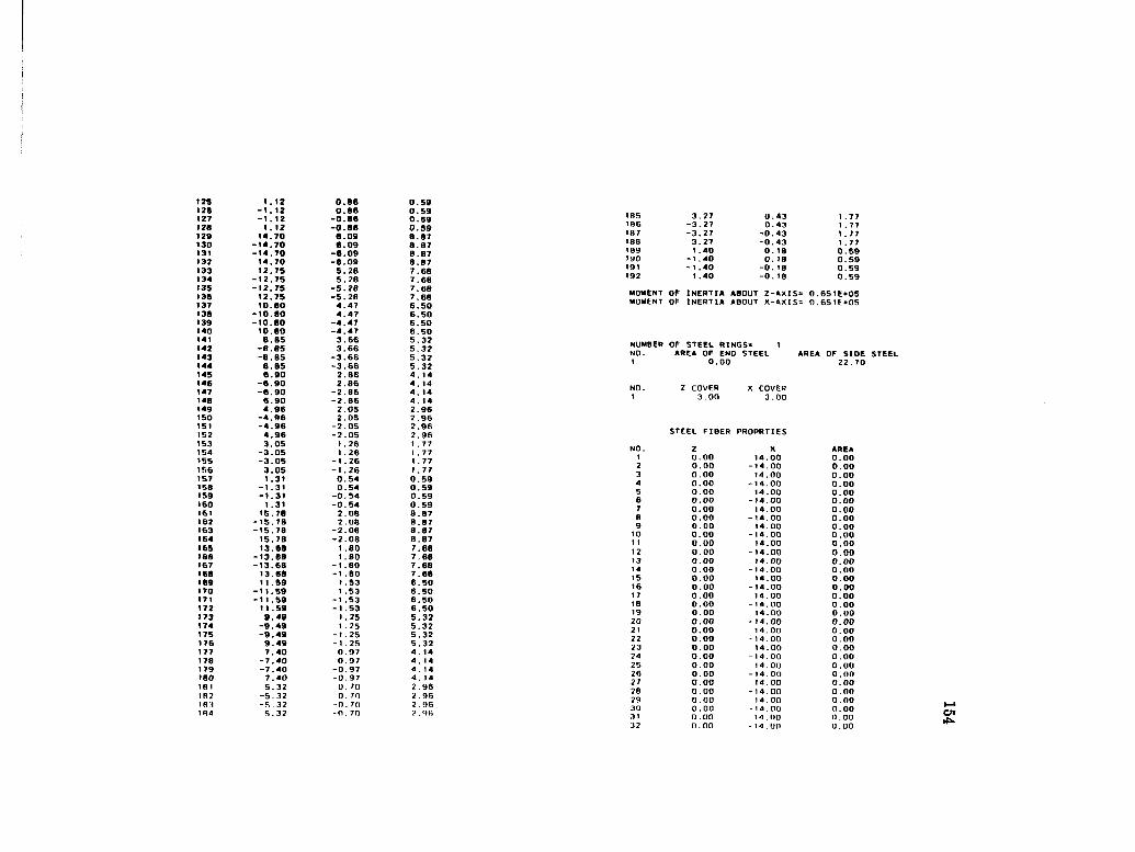
125 1.12 0.86 0.59 126 -1.12 0.86 0.59 127 -1.12 -0.06 0.59 126 1.12 -0.88 0.59 129 14.70 8.09 8.87 130 -14.70 6.09 8.87 131 -14.70 -6.09 8.87 132 14.70 -6.09 8.87 133 12.75 5.28 7.68 134 -12.75 5. 28 7.68 135 -12.75 -5.28 7.68 136 12.75 -5.28 7.68 137 10.80 4.47 6.50 136 -10.80 4.47 6.50 139 -10.80 -4.47 6.50 140 10.00 -4.47 6.50 141 8.65 3.66 5.32 142 -8.85 3.66 5.32 143 -8.85 -3.66 5.32 144 8.85 -3.66 5.32 145 6.90 2.86 4. 14 146 -6.90 2.86 4. 14 147 -6.90 -2.06 4. 14 140 6.90 -2.86 4. 14 149 4.96 2.05 2.96 ISO -4.96 2.05 2.96 151 -4.96 -2.05 2.96 152 4.96 -2.05 2.96 153 3.05 1.26 1 . 77 154 -3.05 1 .26 1 .77 155 -3.05 -1.26 1 . 77 156 3.05 -1.26 1.77 157 1.31 0.54 0.59 156 -1.31 0.54 0.59 159 -1.31 -0.54 0.59 160 1.31 -0.54 0.59 161 15. 78 2.00 0.07 162 -15.78 2.08 0.87 163 -15.70 -2.06 0.07 164 15.78 -2.08 8.87 165 13.68 1 .80 7.68 166 -13.60 1.80 7.68 167 -13.66 -1 .80 7.68 168 13.68 -1 .80 7.60 169 11.59 1 .53 6.50 170 -11.59 1 .53 6.50 171 -11.59 -1 .53 6.50 172 11.59 -1 .53 6.50 173 9.49 1 .25 5.32 174 -9.49 1 .25 5.32 175 -9.49 -1.25 5.32 176 9.49 -1 .25 5.32 177 7.40 0.97 4. 14 178 -7.40 0.97 4. 14 179 -7.40 -0.97 4 . 14 180 7.40 -0.97 4. 14 181 5.32 0. 70 2.96 182 -5.32 0. 70 2.96 18 i -F, .32 -n. 7n 2 .96 1H4 *.32 -n. 7o
105 3. .27 0. .43 1 . .77 186 -3 . 27 0. .43 1 . .77 187 -3. , 27 -0. 43 1 . ,77 188 3. .27 -0. .43 1 , . 77 189 1 . .40 0. . 18 0 .59 190 -1 . .40 0. 10 0. .59 191 -1 , .40 -0. . 10 0. .59 192 1 . .40 -0. . 18 0. .59
MOMENT OF INERTIA ABOUT Z-AXIS* 0.651E+05 MOMENT OF INERTIA ABOUT X-AXIS= 0.651E+05
NUMBER OF STEEL RINGS* 1 NO. AREA OF END STEEL AREA OF SIDE STEEL 1 0.00 22.70
NO. Z COVER X COVER 1 3.00 3.00
STEEL FIBER PROPRTIES
NO. Z X AREA 1 0 00 14 00 0.00 2 0 00 -14 00 0.00 3 0 00 14 00 0.00 4 0 00 -14 00 0.00 5 0 00 14 00 0.00 6 0 00 - 74 00 0.0 0 7 0 00 14 00 0.00 0 0 00 -14 00 0.00 9 0 00 14 00 0.00 10 0 00 -14 00 0.00 1 1 0 00 14 00 0.00 12 0 00 - 14 00 0.00 13 0 00 14 00 0.00 14 0 00 - 1 4 00 0.00 15 0 00 14 00 0.00 16 0 00 - 14 00 0.00 17 0 00 14 00 0.00 18 0 00 - 14 00 0.00 19 0 00 14 00 0.00 20 0 00 - >4 00 0.00 21 0 00 14 00 0.00 22 0 00 - 14 00 0.00 23 0 00 14 00 0.00 24 0 00 - 14 00 0.00 25 0 00 14 00 0.00 26 0 00 - 14 00 0.00 27 0 00 14 00 0.00 28 0 00 - 14 00 0.00 29 0 00 1 4 00 0.00 30 0 00 - 14 00 0.00 31 0 00 14 00 0 . 00 32 0 00 14 00 0.00
155
ooSoocoooSoooooiooooooooooooooooiooSooooo00000000oooicocoioi 0 0 0 0 0 0 0 0 0 0 0 0 0 0 0 0 0 0 0 0 0 0 0 0 0 0 0 0 0 0 0 0 0 0 0 0 0 0 0 0 0 0 0 0 0 0 0 0 0 0 0 0 0 0 0 0 0 0 0 3
oooooooooooooooooooooooioooooooooooooooooooooioooooooSocoiii I I I 1 I I I I I 1 I I I I I I I I I I I I I I I I I 1
ggiSgg§iiiiggg§g§gggiigggg§iggg§gggigggggggggggg§iigg§g|giil ooooooooooooooooooooooooooooooooooooooooooooooooooooooooocsc
S5S§£SS§5SSSSS£i§2=2s:E2^22SjSSSssKass5Sssssssss;?5;S'S;f
gggggggggggggggggggggggggggggggggggigggggggggggggggglggggggg ooooooooooooooooooooooooooooooooooooooooooooooooooooooccoccc
gggggggggggggggggggggggggggggggggggggggggggggggggggggggggiii
~ T i i i i • » i i i i i • • i i i » • « i < • • i 1 • • • '
ggggiggggggggggggggggggggigggggggggggggggggggigggigggggggggg 000000000000000000000000000000000000000000000000000000000000
ssBSfisgs^ssssss^sssssssESSS.ssssssggs^s^KSKSssssssssssssss!
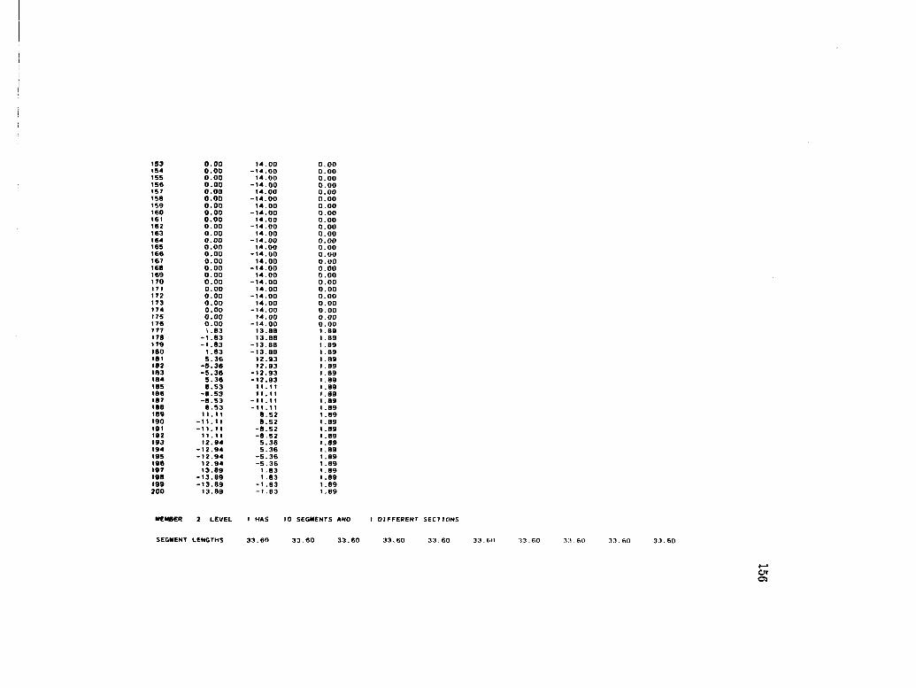
*53 0 00 14 00 0 00 154 0 00 -14 00 0 00 155 0 00 14 00 0 00 156 0 00 -14 00 0 00 157 0 00 14 00 0 00 158 0 00 -14 00 0 00 159 0 00 14 00 0 00 160 0 00 -14 00 0 00 161 0 00 14 00 0 00 162 0 00 -14 00 0 00 163 0 00 14 00 0 00 164 0 oo -14 00 0 00 165 0 00 14 00 0 00 166 0 00 -14 00 0 00 167 0 00 14 00 0 00 168 0 00 -14 00 0 00 169 0 00 14 00 0 00 170 0 00 -14 00 0 00 171 0 00 14 00 0 00 172 0 00 -14 00 0 00 173 0 00 14 00 0 00 174 0 00 -14 00 0 00 175 0 00 T4 00 0 00 176 0 00 - 14 00 0 00 177 1 83 13 88 1 89 178 -1 83 13 88 1 89 179 -1 83 -13 88 1 89 180 1 83 -13 88 1 89 181 5 36 12 93 1 89 182 -5 36 12 93 1 89 183 -5 36 -12 93 1 89 184 5 36 -12 93 1 89 185 8 53 1 1 11 1 89 186 -8 53 11 11 1 89 187 -8 53 -11 1 1 1 89 188 8 53 -1 1 1 1 1 89 189 1 1 1 1 8 52 1 89 190 -1 1 11 8 52 1 89 191 -1 1 11 -8 52 1 89 192 11 11 -8 52 1 89 193 12 94 5 36 1 89 194 -12 94 5 36 1 89 195 -12 94 -5 36 1 89 196 12 94 -5 36 1 89 197 13 89 1 83 1 89 198 -13 89 1 83 1 89 199 -13 89 -1 83 1 89 200 13 89 -1 B3 1 B9
10 SEGMENTS ANO I DIFFERENT SECTIONS
SEGMENT LENGTHS
Of O

THE MEMBER CROSS-SECTION IS SOLID
CONCRETE FIBERS WILL BE MODELLED AS UNCONFINED CONCRETE
STEEL FIBERS ARE GENERATED BV THE PROGRAM
CROSS-SECTION TYPE 1
Z-OIMENSION • 24.00 X-D1MENSION • 48.00
CONCRETE FIBER PROPERTIES
NO. z X AREA 1 -10.80 22.80 5.76 2 -8.40 22.80 5.76 3 -B.00 22.80 5.76 4 -3.80 22.80 5.76 5 -1.20 22.80 5.76 6 1.20 22.80 5.76 7 3.60 22.80 5.76 8 8.00 22.80 5.76 9 8.40 22.80 5.76 to 10. BO 22.80 5.76 11 -10.80 20.40 5.76 12 -8.40 20.40 5.76 13 -8.00 20.40 5.76 14 -3.60 20.40 5. 76 15 -1.20 20.40 5.78 IB 1.20 20.40 5.76 1? 3.80 20.40 5.76 IB 8.00 20.40 5.76 19 8.40 20.40 5.76 20 10.60 20.40 5.76 21 -10.60 16.00 5.76 22 -6.40 18.00 5.76 23 -8.00 18.00 5.76 24 -3.80 18.00 5.76 2S -1.20 18.00 5.76 2B 1.20 18.00 5.76 27 3.60 18.00 5.76 28 6.00 16.00 5.76 29 6.40 16.00 5.76 30 10.80 16.00 5.76 31 -10.60 15.60 5.76 32 -B.40 15.60 5.76 33 -6.00 15.60 5. 76 34 -3.60 15.60 5.76 35 -1.20 15.60 5.76 38 1.20 15.60 5.76 37 3.60 15.60 5.76 38 6.00 15.60 5.76 39 8.40 15.60 5,76 40 10.60 15.60 5. 76 4 1 -10.60 13. 20 5. 76 42 -8.40 13.70 5. 76 43 -6.00 13.70 ^, 76
44 -3 .60 13.20 5 .76 45 -1 .20 13. 20 5 .76 46 1 .20 13.20 5 .76 47 3 .60 13.20 5 .76 48 6 .00 13.20 5 .76 49 B. .40 13.20 5 . 76 50 10 .80 13.20 5 .76 51 -10 .80 10.60 5. .76 52 -8 .40 10.60 5. .76 53 -6. .00 10.80 5. .76 54 -3 .60 10.80 5 .76 55 -1 . 20 10.80 5 .76 56 1. .20 10.80 5. .76 57 3. .60 10.80 5 .76 58 6 .00 10.80 5. .76 59 8 .40 10.80 5. .76 60 10. .80 10.60 5. .76 61 -10. .80 6.40 5. .76 62 -8 .40 8.40 5, .76 83 -6, .00 8.40 5. .78 64 -3. .60 8.40 5, . 76 65 -1. .20 8. 40 5. .76 66 1, . 20 8.40 5, .76 67 3. .60 6.40 5. .76 68 6. .00 8.40 5. .76 69 8. .40 8.40 5, .76 70 10. .60 8.40 5. . 76 71 -10, ,80 6.00 5. .76 72 -8. .40 6.00 5. .76 73 -6 .00 6.00 5 .76 74 -3. .60 6.00 5. .76 75 -1 . .20 6.00 5. . 76 76 1 . .20 6.00 5. ,76 77 3. .60 6.00 5. . 76 78 6. .00 6.00 5. 76 79 8. .40 6.00 5. .76 60 10, .80 6.00 5. .76 81 -10. .80 3.60 5. 76 82 -8. .40 3.60 5. 76 63 -6. 00 3.60 5. 76 04 -3. 60 3.60 5. 76 85 -1 . 20 3.60 5. 76 66 1 . 20 3.60 5. 76 67 3. .60 3.60 5. 76 88 6. 00 3.60 5. 76 69 8. 40 3.60 5. 76 90 10. .80 3.60 5. .76 91 -10. 80 1 . 20 5. 76 92 -8. 40 1 .20 5. 76 93 -6. 00 1 .20 5. 76 94 -3. .60 1 . 20 S. 76 95 -1 . 20 1 . 20 5. 76 96 1 . 20 1 . 20 5. 76 97 3. 60 1 . 20 5. 76 96 6. 00 t . 20 5. 76 99 fl. 40 1 . 20 5. 76 100 10. 60 1 . 20 5. 76 101 - 10. AO - 1 . 70 5. 76 H>2 -B . 40 - 1 . 20 S. 76 103 -6. 00 -1 . ?n 5. 76

104 -3.60 -1 . 20 5. 76 105 -1.20 -1 . 20 5. 76 106 1.20 -1 . .20 5. 76 107 3.60 -1 . 20 5. 76 108 6.00 -1 . 20 5. 76 109 6.40 -1 . .20 5. 76 1 10 10.60 -1 . .20 5. 76 1 1 1 -10.80 -3. 60 5. 76 112 -6.40 -3, .60 5. 76 113 -6.00 -3. .60 5. 76 1 14 -3.60 -3. 60 5. 76 1 15 -1.20 -3. .60 5. 76 116 1.20 -3. .60 5. 70 117 3.60 -3. .60 5. 76 t re 6.00 -3. 60 5. 76 1 19 6.40 -3. .60 5. 76 120 10.80 -3. .60 5. 76 121 -10.80 -6. .00 5. 76 122 -8.40 -6. 00 5. 76 123 -6.00 -6. .00 5. 76 124 -3.60 -6. .00 5. 76 125 -1.20 -6. .00 5. 76 126 1.20 -6. .00 5. 76 127 3.60 -6. .00 5. 76 126 6.00 -6. .00 5. 76 129 8.40 -6. .00 5. .76 130 10.80 -6. .00 5. .76 131 -10.60 -8. .40 5. ,76 132 -8.40 -8 .40 5. . 76 133 -6.00 -B. .40 5. .76 134 -3.60 -8 .40 5. 76 135 -1 .20 -6. .40 5. .76 136 1.20 -8 .40 5. .76 137 3.60 -8. .40 5. 76 136 6.00 -8 .40 5. .76 139 8.40 -8 .40 5. .76 140 10.80 -8. .40 5 .76 141 -10.80 -to .80 5. 76 142 -8.40 -10 .80 5. .76 143 -6.00 -10 .60 5. .76 144 -3.60 -10 .60 5. .76 145 -1.20 -10 .80 5. .76 146 1.20 -10 .BO 5. .76 147 3.60 -10 .60 5 .76 146 6.00 -10 .80 5. .76 149 6.40 -10 .60 5. .76 150 10.80 -10 .80 5 .76 151 -10.80 -13 . 20 5. . 76 152 -8.40 -13 .20 5 .76 163 -6.00 -13 . 20 5. .76 154 -3.60 -13 . 20 5 . 76 155 -1 .20 -13 . 20 5. .76 156 1.20 -13 .20 5. . 76 157 3.60 -13 .20 5. .76 15B 6.00 -13 . 20 5 .76 159 B. 40 -13 .20 5 . 76 160 10.00 - 13 . 20 5 . 76 161 -10.00 -15 .60 f, . 76 162 -8.40 - 15 .60 r> . 76 163 -6.00 - 15 .60 b . 76
164 -3. .60 -15. 60 5. 76 165 -1 . .20 -15, .60 5. 76 166 1 . .20 -15. .60 5. 76 167 3. .60 -15. 60 5. 76 16B 6. .00 -15. .60 5. 76 169 8. .40 -15, .60 5. 76 170 10. .80 -15. .60 5. 76 171 -10. .80 -18. .00 5. 76 172 -8. .40 -18, .00 5. 76 173 -6. .00 -18. .00 5. 76 174 -3. .60 -IB. .00 5. 76 175 -1. .20 -IB. 00 5. 76 176 1, .20 -18. .00 5. 76 177 3. .60 -IB. .00 5. .76 178 6. .00 -18. 00 5. 76 179 6 . .40 -IB. .00 5. 76 1 BO 10. .80 -18. .00 5. 76 161 -10 .80 -20. .40 5. .76 182 -8. .40 -20. .40 5. 76 183 -6. .00 -20. .40 5. 76 184 -3 .60 -20. .40 5. .76 1B5 -1 .20 -20. .40 5. .76 186 1. .20 -20. .40 5. 76 187 3 .60 -20. .40 5. . 76 188 6 .00 -20. .40 5. , 76 189 0 .40 -20 .40 5. .76 190 10 .80 -20. .40 5. 76 191 -10 .60 -22. .80 5. .76 192 -8 .40 -22 .80 5. .76 193 -6 .00 -22 .80 5. .76 194 -3 .60 -22. .80 5. 76 195 -1 .20 -22. .80 5, .76 196 1 .20 -22 .80 5. .76 197 3 .60 -22. .80 5. .76 198 6 .00 -22 .80 5. 76 199 8 .40 -22 .80 5. .76 200 10 .80 -22 .80 5. .76
MOMENT OF INERTIA ABOUT Z-AXtS» 0.22IE+06 MOMENT OF INERTIA ABOUT X-AXIS= 0.547E*05
NUMBER OF STEEL RINGS- 1 NO. AREA OF ENO STEEL AREA OF SIDE ST6CL 1 0.00 11.52
2 COVER X COVER 3.00 3.00
STEEL FIBER PROPERTIES
2 X A R E A -8.73 21.00 0.00 - 8 . 1 0 2 1 . 0 0 0 . 0 0 -7.64 21.00 0.00 Cn oo

11 0 ll(> P 1 ill) H-» ? 1
11 1) zv ft 01) 6-1 11 {) tt'» i I -00 6-l?l i { (1 so L< -00 fc-L 1 0 1 p z \ -00 6-61 1 L 1 0 IL I I -00 6-81 t I 1 0 Pi 1 1 -00 6-L i I ZI 0 09 01 -00 6-91 1 11 0 96 6-00 6-SI i Z 1 0 iU b-00 6-P1 I I I 0 65 H-00 6-£11 Zl 0 56 L-00 6-Zl 1 IX 0 z c L -00 6-1 1 1 Li 0 89 9-00 6-01 1 I l 0 SO 9-00 6-601 IX 0 1 P S-00 6-801 I X 0 LL P-00 6-ZOl IX 0 Pi P-00 6-901 11 0 OS £-00 6-SOI IX 0 98 Z-00 6-»0I IX 0 CZ z-00 6-eoi Zl 0 65 1 -00 6-ZOl L X 0 56 0-00 6-101 II 0 ZC 0-00 6-001 Z I 0 ZC 0 00 6-66 LI 0 56 0 00 6-86 LI 0 65 I 00 6-Z6 Li 0 ez z 00 6-96 L X 0 98 z 00 6-S6 L X 0 OS £ 00 6-*6 L X 0 PI P 00 6-£6 t i 0 LL P 00 6-Z6 LI 0 IP S 00 6-16 L X 0 SO 9 00 6-06 LI 0 69 9 00 6-68 L X 0 ZC L 00 6-88 L X 0 S6 L 00 6-LB L X 0 65 8 00 6-98 L X 0 tz 6 00 6-58 LI 0 98 6 00 6-PB Zl 0 OS 01 00 6-£8 L X 0 Pi 1I 00 6-28 L I 0 LL X X 00 6-18 L 1 0 X¥ zx 00 6-08 L 0 SO CI 00 6-6 L L X 0 89 ei 00 6-BL L I 0 Zt PX 00 6-LL Li 0 56 PX 00 6-9 L L X 0 6S SI 00 6-S L L X 0 zz 91 00 6-PL Zl 0 98 91 00 6-CL zi 0 OS Li 00 6-ZL L X 0 Pi 81 00 6-I L L X 0 LL 81 00 6-0 L L X *0 iP 61 00 6-69 zi 0 SO oz 00 6-89 LX 0 89 oz 00 6-19 00 *0 00 12-ZL e 99 00 0 00 12-ei e S9 00 *0 00 12-*9 L P9
01)' 0 00* u-60* I £9 00 0 (JO IZ-55 9 Z9 00" 0 00" IZ-00 9 19 00 0 00* IZ-Sf ' 5 09 00" 0 00' IZ-16' P 6S 00* 0 00 12-9£' > 05 00' 0 00* 12-28' C ZS 00' 0 00' 12-LZ c 9S 00-0 00' 12-ZC 2 SS 00' 0 00' 12-81' I »S 00' 0 00' 12-P9 1 es 00' 0 00' IZ-60 I 2S 00' 0 00* IZ-SS 0 IS 00' 0 00' 12-00 0 OS 00' 0 00' 12-ss 0-6» 00' 0 00' 12-60 1 -BP 00' 0 00' 1Z-99 ' l-LP 00 0 00' 12-ei 2-9P 00 0 00' 12-Zl 2-St 00' 0 00' 12-u '£-PP 00 0 00' 12-29 'C-ZP 00 0 00' 12-9C IP 00 0 00' 12-16 • *-ip 00 0 00' 12-S» *s-QP 00 0 00' 1Z-00 "9-6E 00 0 00' 12-ss 9-9£ 00 0 00' 12-60 l-Z£ 00 0 00' 12-»9 ' L-9£ 00 0 00' 12-91 9-SC 00 0 00' 12-ZL 9-PZ 00 0 00' 12 ZL 8 ZZ 00 0 00' 12 91 '9 IZ 00 0 00' 12 »9 l IZ 00 0 00' 12 60 'I oz 00 0 00' 12 SS 9 62 00 0 00' 12 00 '9 92 00 0 00' 12 S» '8 LZ 00 0 00' 12 16 '¥ 92 00 0 00' 12 9C '¥ SZ 00 0 00' tz 29 'Z PZ 00 0 00' 12 LZ Z £2 00 0 00' 12 ZL 'Z ZZ 00 0 00' 12 91 '2 12 00 0 00' 12 *9 * 1 02 00 0 00 12 60 ' t 61 00 0 00' 12 SS 0 91 00 0 00' 12 00 0 Zt 00 0 00' 12 SS 0-91 00 0 00' 12 so • l-Si 00 0 00' U •9 • 1-PI 00 0 00' 1Z 91 2-CI 00 0 00' 12 Zl 2-21 00 0 00' 12 LZ 'C-1 1 00 0 00' 12 29 '£-01 00 0 00' IZ 9C " P-6 00 0 00' 12 16 9 00 0 00' 12 sr *S-I 00 0 00' 12 00 *9-9 00 0 00' 12 Sfi *9-S 00 0 00' 12 60 'l-P

I I
I I I I I I t
£
«(A
lO(O
0<
DI0
lOC
tt0
O«
)l0
ttlO
0lf
ilD<
lO(0
<6
l0«
«e
00
lO«
><
O«
0tf
(0tf
<O
iO«
(O<
0«
tf«
(00
«e
0«
fi(0
««
0«
»C
o o
o o
oooo
oooo
oooo
oooo
oooo
oooo
oooo
oooo
oooo
oooo
oooo
oooo
oooo
oooo
O
OO
OO
OO
OO
OQ
OO
OO
OO
OO
OO
OO
OO
OO
OO
OO
OO
OO
OO
OO
OO
OO
OO
OO
OO
OO
OO
OO
OO
OO
O
— —
I I
I I
I I
I I
» I
I I
I 'O
^io
o^s
ota
iwik
AU
MM
'OO
OO
oN
iMU
AJ
kU
ioia
^^a
ioie
o-
'^O
MJI
IfiU
aiO
kN'V
8N
UII
0U
UI0
UlM
aU
I-'4
»O
OIU
<0
U)M
ISU
I'-
ft0
9u
ifi(
nN
>a
J*"s
*oo
iuio
uiN
NiJ
iiou
o)0
»^^
mcB
NU
t<8
ua
)0*
I I
I I
I 6
6o
o«
MM
u»
*uiA
a<
4s
Bto
i0O
«
I «
I I
I I
I I
I • u
uwki
kUio
ioiN
isav
oooo
caa^
oiA
Ui
4b
oa
uiD
uiN
au
i-<
s»
oa
aQ
k^^u
iCD
Nu
i J
^UI(
BN
(jl(
OU
O)O
A^'
tf9
CP
(lt'
^k0
9U
(0
soso
oooo
oooo
oooo
aooo
oooo
oooo
oooo
oooo
oooo
oooo
oooo
oooo
oooo
oooo
ifiioi
O!Ci
0ion)
i0ioa
osiB
oiB
S>i
(7)U
lftU
KI-
<OI0
3)^l
TlU
1b
<0<D
<0<0
C0(0(
0<O(
0^<0<
0(0<0
(0 O
OO
OO
OO
OO
OO
OO
OO
oo
oooo
oooo
oooo
o
oooo
oooo
oooo
ooo
091

••• LOAD CASE
NUMBER OF LOAO INCREMENTS* 1 NUMBER OF MEMBERS LOAOEO = 0 PRINTING INOEX = 1
NUMBER OF FRAME JOINTS LOADED*
JOINT NO. FORCE-X FORCE-V FORCE-Z MOMENT-X MOMENT-V MOMENT-Z 4 O.OOOE+OO -0.113E+07 O.OOOE+OO O.OOOE+OO O.OOOE+OO O.OOOE+OO
o

MEMBER 1
LOAD INCREMENT 1 •••••••••••••••••A*
>>> DISPLACEMENTS <<<
JOINT NO. 1 OISPL.-X O.OOOE+OO
OISPL.-V 0.OOOE+OO
OISPL.-Z 0.OOOE+OO
ROTATION-X 0.OOOE+OO
ROT ATION-V o.oooe»oo
ROTATION-2 0 . OOOE* 00
JOINT NO. 2
OISPL.-X 0.106E-03
DISPL.-Y -0.502E-05
OISPL.-Z -0.662E-13
ROTATION-X -0.650E-14
ROTATION-V 0. I05E-13
ROTATION-Z -0. 107E-04
JOINT NO. 3
OISPL.-X 0.425E-03
OISPL.-V -0. 100E-04
DISPL.-Z -0.25 IE-I 2
ROTATION-X -0.120E-13
ROTATION-V 0.209E- 1 3
ROTATION-Z -0.215E-04
JOINT NO. 4
OISPL.-X 0.956E-03
OISPL.-V -0.1S1E-04
OISPL.-Z -0.535E-12
ROTATION-X -0.165E-13
ROTATION-V 0.314E- 13
ROTATION-Z -0.322E-04
JOINT NO. S
OISPL.-X 0. 170E-02
DISPL.-V -0.201E-04
OISPL.-Z -0.099E-12
ROTATION-X -0.200E-13
ROTATIOM-V 0 . 4 18E-13
ROTA T fON-Z -0.429E-04
JOINT NO. 6
OISPL.-X 0.265E-02
DISPL.-V -0.25IE-04
OISPL.-Z -0. 132E-»I
ROTATION-X -0.225E-13
ROTATION-V 0.523E-13
ROTATION-Z -0.536E-04
JOINT NO. 7
OISPL.-X O.302E-O2
OISPL.-V -0.301E-04
DISPL.-Z -0.170E-11
ROTATION-X -0.240E-I3
ROTATION-V 0.627E- 1 3
ROTATION-Z -0.644E-04
JOINT NO. e
OISPL.-X 0.520E-02
OlSPL.-V -0.351E-04
OISPL.-Z -0.227E-1t
ROTATION-X -0.246E-\3
ROTATION-V 0.732E- I 3
ROTATION-Z -0.751E-04
JOINT NO. 9
OISPL.-X 0.6S0E-02
DISPL.-V -0.40IE-04
DISPL.-Z -0.275E-11
ROTATION-X -0.241E-13
ROTATION-V 0.036E-13
ROTATION-Z -0.B58E-04
JOINT NO. 10
OISPL.-X 0.06OE-O2
OISPL.-V -0.452E-04
OISPL.-Z -0.32IE-tI
ROTATION-X -0.226E-?3
ROTATION-V 0.94IE-13
ROTATION-Z -0.966E-04
JOINT NO. 1 1 OISPL.-X 0.106E-01
DISPL.-Y -0.502E-04
DISPL,-Z -0.364E-11
ROTATION-X -0.201E- 13
ROTATION-V 0 . 105E-12
ROTATION-Z -0. 1 (17E -03
>>> FORCES <**

163

seg.NO. 9 END-A
END-B
SEG.NO. 10 END-A
-0.875E*00
FOACE'X
0.750E+00
-0.750E*00
FORCE-X
0.563E+00
-0.563E+00
-0. 1 t2E+04
FORCE-V
0. 1 12E*04
-0.112E*04
FORCE-V
0. 1 12E+04
-0.1I2E*04
-0.083E-O6
FORCE-Z
0.8B3E-06
-0.B83E-06
FORCE-Z
0.883E-06
-O.B03E-O6
0. 172E-04
MOMENT-X
-0.172E-04
0.346E-04
MOMENT-X
-0.346E-04
0.521E-04
0. 147E-03
MOMENT-V
-0.147E-03
0. 147E-03
MOMENT-V
-0.147E-03
0. 147E-03
-0.»8BE*06
MOMENT-Z
0. 1B6E+06
-0. 1R8E+06
MOMENT-Z
0. yB8E*06
-0.188E+06

MEMBER 2 ••••••••••••
LOAO INCREMENT
>>> DISPLACEMENTS <<<
JOINT NO. 12
DISPL.-X 0.OOOE+OO
OISPL.-V 0.OOOE+OO
DISPL.-Z 0. OOOE+OO
ROTATION-X 0.OOOE+OO
ROTATION-V ROTATION-Z 0.OOOE+OO 0.OOOE+OO
JOINT NO. 13
OISPL.-X 0. 106E-03
DISPL.-V -0.506E-02
OISPL.-Z 0.637E-13
ROTATION-X 0.625E-14
ROTATION-V 0. 104E-13
ROT AT ION-Z -0.107E-04
JOINT NO. 14
DISPL.-X 0.425E-03
DISPL.-V -0.101E-01
DISPL.-Z 0.241E-12
ROTATION-X 0. 1 15E-13
ROTATION-V 0.209E-13
ROTA TION-Z -0.215E-04
JOINT NO. 15
DISPL.-X 0.956E-03
OISPL.-V -0.1S2E-01
DISPL.-Z 0.514E-12
ROTATION-X 0. 158E-13
ROTATION-V 0.3I3E-13
ROTATION-Z -0.322E-04
JOINT NO. 16
DISPL.-X 0.170E-02
DISPL.-V - 0 . 2 0 2 E - 0 1
OISPL.-Z O.062E-12
ROTATION-X 0. 192E-13
ROTATION-V O.4I0E-I3
ROTATION-Z -0.429E-04
DISPL.-X 0.265E-02
DISPL.-V -0.253E-01
DISPL.-Z 0. 127E-11
ROTATION-X 0.215E-13
ROTATION-V 0.522E- 13
ROTATION-Z -0.536E-04
JOINT NO. 10
DISPL.-X 0.302E-O2
OISPL.-V -0.304E-01
OISPL.-Z 0. 171E-11
ROTATION-X 0.229E-13
ROTATION-V 0.627E-13
ROTATION-Z -0.644E-04
JOINT NO. 19
DISPL.-X 0.520E-02
DISPL.-V -0.354E-01
DISPL.-Z 0.217E-H
ROTATION-X 0.234E-13
ROTATION-V 0.73IE-13
ROTATION-Z -0.751E-04
JOINT NO. 20
DISPL.-X 0.6B0E-02
DISPL.-V -0.405E-01
DISPL.-Z 0.263E-11
ROTATION-X 0.220E- 13 ROTATION-Y 0.B35E-13
ROTATION-Z -O.05BE-O4
JOINT NO. 2 1
OISPL.-X 0.B60E-02
DISPL.-V -0.455E-01
OISPL.-Z 0.307E-11
ROTATION-X 0.213E-13
ROTATION-V 0.940E-13
ROTATION-Z -0.966E-04
JOINT NO. 2 2
OISPL.-X 0. 106E-01
DISPL.-V -0.506E-01
DISPL.-Z 0.347E-11
ROTATION-X 0. 108E- 13
ROTATION-V 0.104E-12
ROTATION-Z 0 1D7E-0.1
»>> FORCES «•<«

CO CO yo*3«H» II
l - iNJWUN
90*3881 0-
9o»aeui 0 Z-1N3M0N
90+3881 "0-
90*3081 0
Z-J.N3M0H
90+3B81*0-
90*3891 0
Z--LN3W0W
90+3801'0-
90 + 388 I"0
Z-IN3WOW
90*3881 0-
90+3881 0
Z-J.N3W0M
90+3881'0-
90*3081 0
Z-1N3H0H
90+3881'0-
90*3801 0
Z-IN3W0W
K0 iJUl ' I)
A-J.N3MOW
E0-3**t * 0 C0-3Z*l 0-A-1N3H0M
E0-3Z*1 0 eo-3z*i o-
A-1N3M0W
£0-3Zfrl'0
C0-3ZH 0-A-XN3M0M
ro-3z*i o C0-3£*l o-
A-1N3W0W
E0-3Z*l 0
C0-3Z*l 0-
A-IN3W0H
E0-3Z*l " 0 C0-3ZH 0-
A-XN3M0M
C0-3Z1M *0 eo-3z*i o-A-1N3H0W
UU-39UI O
X *1N3M0M
90-3901*0-
*0-3091 0-
X-J.N3N0W
>0-3091 0
f0-30GG0-
X-1N3M0W
*0-30EC*0
*0-300S'0-
X-i.N3W0H
*0-3005*0
*0-30*90-
X-1N3N0N
*0-30£9'0
*0-31*8*0-
X-J.N3M0M
*0-31*8 * 0
£0-3101*0-X-J.H3N0M
CO-3i 01*0
£0-3611'0-
X-1N3M0M
90-3098 0-
Z-3DU03
90-3098 0
90-3090*0-
Z-3Db03
90-3098"0
90-3099*0-
2-33U0J
90-3098 0
90-3090'0-
2-33U04
90-30900
90-3090*0-
Z-33U03
90-30980
90-3090*0-
Z-33M0J
90-30980
90-30900-
2-33U03
90-3090*0
90-3090 * 0-
2-33U03
Z 0 + 3£I I *0
A-j'jaOd
Z0+3EI I 0-
i0*3ClI 0 A-33B03
Z.0+3EII 0-
iO*3EtI'0
A-33M0J
Z0+3CI1 0-Z0+3EIi '0 A-33U04
Z0+3EII 0-iO*3ElI'0
A-33U03
LQ+3CIl '0-
I0*3£lI*0
A-33U03
Z0+3CIl 0-Z0+3CII '0 A-33M03
Z0+3CU *0-Z0+3EII'0 A-3DdOd
00 + 3889 * 0
X-33d0d
00+3G9fi*0-
00+3C9S0
X-3DH03
00+39060-
00+3906'0
X-33U04
0Q+38Z.S' 0-
oo+aazfi'o
X-3DB03
00+31*9*0-
00+31*9*0
X-33d0i
00+31E50-
00+31ES0
X-33U04
00+3SSS0-
00+3SSS0
X-33W0d
V-0N3 0 ON"OSS
9-0N3
V-QN3 I
0M03S
9-ONi
V-0N3 9
* ON * 03S
Q-0N3
V-QN3 S 0HO3S
9-ON3
W-0N3 * 0N03S
8-0N3
V-0N3 C
'QN'oas
9-0N3
V-QN3 I
*ON'OSS
9-0N3
V-0N3 i
'0N03S
00+3SCS0-
00+3969*0
X-33d0i

END-8 *0. 6BBE+00 -0.M3E + 07 0.860E-06 -0.1B1E-04
SEG.NO. 9 EHD-A
FORCE-X
0.625E+00
FORCE-V
0.113E+07
FORCE-Z
-0.860E-06
MOMENT-x
0. 181E-04
ENO-B -0.625E+00 -0.113E+07 0.860E-06 -0.351E-04
SEG.NO. 10 END-A
FORCE-X
0.594E+00
FORCE-V
0.113E*07
FORCE-Z
-0.660E-06
MOMENT-X
0.351E-04
ENO-B -0.594E+00 -0.113E+07 0.860E-06 -0.521E-04
0.147E-03
MOMENT- V
0 . 147F-03
0. 147F-03
MOMENT-V
•0.147E-03
0. I47E-03
o.tun?*no
MOMENT-Z
0. 1 8BE *06
0 . t BflE + 06
MOMENT-Z
0 . 1 B8E*06
0 . 1B8E+06

MEMBER 3
LOAD INCREMENT 1
>» DISPLACEMENTS <<<
JOINT NO. 23
JOINT NO. 24
JOINT NO. 25
JOINT NO. 26
JOINT NO. 27
JOINT NO. 28
JOINT NO. 29
JOINT NO. 30
JOINT NO. 31
JOINT NO. 32
JOINT NO. 33
01SPL.-X 0.106E-01
DISPL.-X 0.106E-01
DISPL.-X 0.106E-01
DISPL.-X 0.106E-01
DISPL.-X 0.106E-01
DISPL.-X 0.F06E-0!
DISPL.-X 0.106E-01
DISPL.-X 0.106E-01
01SPL.-X 0. ".06E-0I
OISPL.-X 0.T06E-0L
DISPL.-X 0. 106E-01
DISPL.-Y -0.502E-04
01SPL.-V -0.406E-02
DISPL.-V -0.877E-02
DISPL.-V -0.140E-0I
DISPL.-V -0.196E-01
DISPL.-V -O.253E-0I
DISPL.-V -0.3116-01
01SPL.-V -0.367E-01
01SPL.-V -0.419E-01
OISPL.-V -0.466E-01
DISPL.-V -0.506E-01
DISPL.-2 -0.364E-I 1
01SPL.-Z -0.597E-11
DISPL.-Z -0.627E-11
DISPL.-Z -0.506E-11
DISPL.-Z -0.283E-11
OISPL.-Z -0.964E-13
DISPL.-Z 0.264E-11
DISPL.-Z 0.487E-11
DISPL.-Z 0.609E-11
DISPL.-Z 0.579E-H
DISPL.-Z 0.347E-11
ROT ATION-X -0.201E-13
ROTATION-X -0.162E-13
ROTATION -X -0.123E-13
ROTATION-X -0.845E-14
ROTATION-X -0.455E-14
ROTATION-X -0.660E-I5
ROTATION-X 0.323E-14
ROTATION-X 0.713E- 14
ROTATION-X 0.110E-13
ROTATION-X 0. 149E-13
ROTATION-X 0. 18BE-13
ROTATtON-V 0.105E-12
ROTATION-V 0.368E-13
ROTAT1ON-V -0. 159E-13
ROTATION-V -0.536E-13
ROTATION-V -0.762E-13
ROTATION-V -0.837C-J3
ROTATION-V -0.762E-13
ROTATION-V -0.537E-13
ROTATION-V -0.160E-13
ROTATION-V 0.367E-13
ROTATION-V 0.104E-12
ROTATION-2 -0. 107E-03
ROT ATION-Z -0. 1 31E-03
ROT AT ION-Z -0. 149E-0:*
ROT ATION-Z -0.162E-03
ROT ATION-Z -0.1G9E-03
ROTATION-Z -0. I72E-OJ
ROTATION-Z -0.I69E-03
ROT ATION-Z -0.162E-03
ROT ATION-Z -0.149E-03
ROTAT T ON-Z -0. 131E-03
ROT A TION-Z -(). 1 0 7 E - 0 .i
>>> FORCES <<<

- - o
- - o
-
-
»
hj m
n
- - z
o o s
o
ui
in s
w
M
m
- - z
- - z
- - z
- - 2
=
£
n *
1 z
a o
z
o
-
z
691

END-B -0.490E-03 -0.112E+04 -0.857E-06 0.5216-04
SEG.NO. FORCE-X 9 END-A -0.249E+00
FORCE-V
0. M2E+04
-0.112E+04
FORCE-Z
0.859E-06
-0.8S6E-06
MOMENT-X
-0.521E-04
0.521E-04
SEG.NO. FORCE-X FORCE-V FORCE-2 MOMENT-X 10 ENO-A -0.249E+00 0.112E*04 0.849E-06 -0.521E-04
ENO-B 0.249E*00 -0.M2E + 04 -0.B46E-06 0.5216-04
0.801E-04
MOMENT-V
0.879E-04
•0.117E-03
MOMENT-V
0. 1 17E-03
-0.146E-03
0.11 3E*06
MOMENT-Z
0. 1 13E + 06
0. 151E + 0R
MOMENT-Z
0. 151E*06 0. 188E+06

••• LOAD CASE 2
NUMBER OF LOAD INCREMENTS^ 200 NUMBER OF MEMBERS LOADEO = 0 PRINTING INDEX * BO
NUMBER OF FRAME JOINTS LOADEO*
JOINT NO. FORCE-X FORCE-V FORCE-Z MOMENT-X MOMENT-V MOMENT-2 3 0.300E+04 0.000E+00 0.OOOE+OO 0.OOOE+OO 0.0006*00 O.OOOC+OO

MEMBER 1 ••••••••••••
LOAD INCREMENT 1 *••••••••*•••••••••
>>> DISPLACEMENTS <<<
JOINT NO. 1 DISPL.-X O.OOOE+OO
DISPL.-V 0.OOOE+OO
OISPL.-Z 0. OOOE+OO
ROTATION-X 0.OOOE+OO
ROTATION-V 0.OOOE+OO
ROTATION-Z 0 . OOOE+OO
JOINT NO. 2 DISPL.-X 0.2B6E-03
DISPL.-V 0.657E-04
DISPL.-Z -0.371E-12
ROTATION-X -0.365E-13
BOTATION-V -0.243E- 1 2
ROTATION-Z -0.284E-04
JOINT NO. 3 DISPL.-X 0.11tE-02
DISPL.-V 0.121E-03
OISPL.-Z -0.141E-11
ROTATION-X -0.676E-13
ROTATION-V -0.406E-12
ROTATION-Z -0.540E-04
JOINT NO. 4
DISPL.-X 0.241E-02 DISPL.-V 0.* 66E-03
DISPL.-Z -0.302E-11
ROTATION-X -0.934E-13
ROTATION-V -0.728E-12
ROT ATION-Z -0.770E-04
JOINT NO. 5
DISPL.-X 0.4!4E-02
DISPL.-V 0.201E-03
DISPL.-Z -0.508E-11
ROTATION-X -0.114E-12
ROTATION-V -0.971E- 12 ROT AT ION-Z -0.972E-04
JOINT NO. 6
OISPL.-X 0.624E-02
DISPL.-V 0.22SE-03
OISPL.-Z -0.749E-11
ROTATION-X -0.129E-17
ROT ATION-V -0.12IE-11
ROT ATION-Z -0.115E-03
JOINT NO. 7
DISPL.-X 0.B67E-02
DISPL.-V 0. 239E-03
OISPL.-Z -0.101E-10
ROTATION-X -0.13BE-\2
ROT ATION-V -0.146E-11
ROT ATION-Z -0.130E-03
JOINT NO. 8
OISPL.-X 0. I I4E-0'
OlSPL.-V 0.243E-03
OISPL.-Z -0.I29E-10
ROTATION-X -0. I42E-J 2
ROTATION-V -O. I70E-I I
ROTATION-Z -0.J42E-03
JOINT NO. 9
DISPL.-X 0. I43E-0:
OISPL.-v 0.236E-03
OISPL.-Z -0.157E-10
ROTATION-X -0.141E-12
ROT ATION-V -0.194E-11
ROTAT1ON-Z -0.151E-03
JOINT NO. 10
DISPL.-X 0.173E-01
OISPL.-V 0.219E-03
DISPL.-Z -0.185E-10
ROTATION-X -0.135E-12
ROTATION-V -0.719E-11
ROT ATION-Z -0. 1 fjBF -01
DISPL.-X 0.205E-01
OISPL.-V 0. 192E-03
DISPL.-Z -0.21OE- 10 ROTATION-X -0. 123E-12
ROTATJON-V -0.743E-11
ROTATION-Z -0. »f,?E-03
>>> FORCES

173
2
s
c
O "
" o
- -o
- -
IN
Z
Ml
O z«z
UJ 0

0.13SE+04 -0.63BE+03 -0.355E-05
FORCC-X SEG.WO. 9 ENO-A -0.13SE+04
FORCE-V
0.63BE+03
0.13SE+04 -0.63BE+03 -0.3556-05
FORCE-Z MOMENT-X
0.355E-05 -0.522E-04
SEG.NO. FORCE-X 10 ENO-A -0.135E+04
FORCE-V
0.63BE+03
FORCE-Z
0.355E-05
0.I35E+04 -0.638E+03 -0.355E-05
MOMENT-X
-0. 123E-03
O.?93E-03
0.229E-02
MOMENT-V
0.229E-02
0.229E-02
MOMENT-V
0.229E-02
•O.229E-02
0 . 1 6 1 E + 0 6
MOMENT-2
0.1616*06 0. 134E+06
MOMENT-Z
0. 134E*06
0.107E+06

MEMBER 2 ••••••••••••
LOAD INCREMENT 1
>>> DISPLACEMENTS <<<
JOINT NO. 12 DISPL.-X O.OOOE+OO
DISPL.-V 0.OOOE+OO
OLSPL.-2 O.OOOE+OO
ROTATION-X O.OOOE+OO
ROTATION-V 0-OOOE+OO
ROTATION-2 O.OOOE+nO
JOINT NO. 13
OLSPL.-X 0.250E-O3
DISPL.-V -0.506E-02
OLSPL.-Z 0.29BE-12
ROTATION-X 0.293E-13
ROTATION-V 0.270E-12
ROTATION-2 -0.2S7E-04
JOINT NO. 1 4
DISPL.-X 0.100E-02
DISPL.-V -0.101E-01
DISPL.-2 0.1136-11
ROTATION-X 0.543E-13
ROTATION-V 0.539E-12
ROTATION-2 -0.493E-04
JOINT NO. IS
OLSPL.-X 0.220E-02
DISPL.-V -0.152E-01
OLSPL.-2 0.242E-1 1
ROTATION-X 0.751E- 13 ROTATION-V O.B09E-1?
ROTATION-Z -0.7O0E-O4
JOINT NO. 16 OLSPL.-X 0.379E-02
DISPL.-V -0.203E-01
DISPL.-2 0.4006-11
ROTATION-X 0.915E-13
ROTATION-Y 0. 108E-11
ROTATION-Z -0.902E-04
JOINT NO. 17
OLSPL.-X 0.575E-02
OLSPL.-V -0.253E-01
DISPL.-Z 0.602E-11
ROTATION-X 0.104E- 12
ROTATION-V 0. 135E- 1 1
ROTAT10N-Z -0. 108E-03
JOINT NO. 18
DISPL.-X 0.804E-02
DISPL.-V -0.304E-01
DISPL.-Z 0.815E-11
ROTATION-X 0. 1 1 IE- 1 2
ROTATION-V 0.162E-11
ROTATION-Z -0. 123E-03
JOINT NO. 19
DISPL.-X 0.106E-01
DISPL.-V -0.354E-01
DISPL.-2 0.104E-10
ROTATION-X 0. 1 15E-12
ROTATION-V 0.1B9E-11
ROTATION-Z -0.136E-03
JOINT NO. 20 DISPL.-X 0.134E-01
OLSPL.-V -0.405E-01
DISPL.-2 0.127E-10
ROTATION-X 0. 114E-12
ROTATION-V 0.216E-11
ROTATION-Z -0. 147E-03
JOINT NO. 2 1
D1SPL.-X 0.164E-01
DISPL.-V -0.456E-01
OLSPL.-2 0.149E-10
ROTATION-X 0. 109E-12
ROTATION-V 0. 243E-11
ROTATION-Z -0 . 1 F>6E - 03
JOINT NO. 22
01SPL.-X 0.196E-01
DISPL.-V -0.S06E-01
OLSPL.-Z 0.169E-10
ROTATION-X 0.992E-13
ROTATION-V 0.270E-11
ROT ATION-Z -0. 1K2E-0.1
>>> FORCES <<<
- 1 Cn

FORCE-X
-0.1856*04
0.165E+04
FORCE-X
-0.I65E*04
0.1B5E*04
FORCE-X
-0.165E+04
0.165E+04
FORCE-X
-0.165E*04
0.165E+04
FORCE-X
-0.I65E+04
0.165E*04
SEG.NO. 1 END-A
END-B
SEG.NO. 2
END-A
END-B
SEG.NO. 3 END-A
END-B
SEG.NO. 4 END-A
END-B
SEG.NO. S END-A
END-B
SEG.NO. 6 END-A
END-B
SEG.NO. 7 ENO-A
ENO-B
SEG.NO. 8 ENO-A
FORCE-X
-0.I65E+04
0.165E*04
FORCE-X
-0.1B5E+04
0.165E*04
FORCE-x
-0.165E*04
FORCE-V
0. 1 13E+07
-0.113E+07
FORCE-V
0.1!3E*07
-0.113E+07
FORCE-V
0.113E*07
-0.113E+07
FORCE-V
0.113E*07
-0.113E+07
FORCE-V
0. 1 13E+07
-0.113E*07
FORCE-V
0. 1 1 3E + 07
-0.I>3E*07
FORCE-V
0. 1>3E*07
-0.113E*07
FORCE-V
0.1 13E+07
FORCE-2
-0.3S0E-05
0.350E-05
FORCE-Z
-0.350E-05
0.350E-05
FORCE-Z
-0.350E-05
0.350E-05
FORCE-Z
-0.350E-05
0.350E-05
FORCE-Z
-0.350E-05
0.350E-05
FORCE-Z
-0.349E-05
0.349E-05
FORCE-Z
-0.350E-05
0.350E-05
FORCE-Z
-0.349E-05
MOMENT-X
-0.514E-03
0.445E-03
MOMENT-X
-0.445E-03
0.375E-03
MOMENT-X
-0.375E-03
0.304E-03
MOMENT-X
-0.304E-03
0.234E-03
MOMENT-X
-0.234E-03
0.163E-03
MOMENT-X
-0.163E-03
0.917E-04
MOMENT-X
-0.917E-04
0.205E-04
MOMENT-X
-0. 205E -04
MOMENT-V
-0.347E-02
0 . 347E-0?
MOMENT-V
-0.347E-02
0.347E-02
MOMENT-Y
-0.347E-02
0.347E-02
MOMENT-V
-0.347E-02
0.34 7E-02
MOMENT-V
-0.347E-02
0.347E-02
MOMENT-V
-0.347E-02
O. 347E-02
MOMENT-V
-0.347E-02
0.347E-02
MOMENT-V
• O . :\4 7T -0?
MOMENT-Z
0 . 444E*0fi
-0.411E•OB
MOMENT-Z
0.4 i1E*06
-0.370E+O6
MOMENT-Z
0.37BE+06
-0.34SE*06
MOMENT-2
U.345E•06
-0.S\1E+06
MOMENT-Z
0.311E + 06
-0 . ?7 7E* 06
MOMENT-Z
0.27 7E*06
-0.?43E*Of>
MOMENT-Z
0 . 243E+0B
-0.2U9E»««
MOMfNT /
O -'It'll • Oh

0.16SE+04 -0.113E+07 0.349E-05 -0.507E-04 0.347E-02
SEC.NO. 9 ENO-A
FORCE-X
-0. 165E+04
0.te5E+04 -0.»>3E+07
FORCE-V FORCE-Z MOMENT-X MOMENT-V
0.113E+07 -0.350E-05 0.507E-04 -0.347E-0?
0.350E-05 -0.122E-03 0.347E-02
5EG.N0. FORCe-X FORCE-V FORCE-Z MOMENT-X MOMENT-v 10 ENO-A -0.165E+04 0.113E*07 -0.350E-05 0.122E-03 -0.347E-02
ENO-B 0.165E+04 -0.113E+07 0.350E-05 -0.193E-03 0.347E-D2
0 . » 75E »0<i
MOMENT-Z
0 . 1 75E+06
•0. 14 JE*06
MOMENT-Z
0 . 14 f E*06
•0.107E+06

MEMBER 3 •••••••*••••
LOAD INCREMENT 1
>>> DISPLACEMENTS <<<
JOINT NO. 23 DISPL.-X 0.205E-01
OISPL.-V 0. 192E-03
DISPL.-2 -0.210E-10
ROTATION-X -0.123E-12
R0TAT1ON-V -0.243E-I 1
ROTAT10N-Z -0.162E-03
JOINT NO. 24
DISPL.-X 0.2046-01
DISPL.-V -0.517E-02
DISPL.-Z 0.420E-10
ROTATION-X -0.100E-12
ROTATION-Y -0.174E-11
ROT ATION-Z -0.157E-03
JOINT NO. 25
DISPL.-X 0.202E-01
DISPL.-V -0.104E-0I
DISPL.-Z 0.862E- 1 0
ROTATION-X -0.779E-13
ROTATION-V -0.789E-12
ROTATION-Z -0.153E-03
JOINT NO. 26
01SPL.-X 0.201E-01
DISPL.-V -0.154E-01
DISPL.-Z 0.108E-09
ROTATION-X -0.554E-13
ROTATION-V -0.467E-12
ROTAT1ON-2 -0.149E-03
JOINT NO. 27
OISPL.-X 0.201E-01 OISPL.-V -0.204E-01
DISPL.-Z 0.119E-09
ROTATION-X -0.330E-13
ROTATION-V -O.136E-1?
ROTATION-2 -O. 145E-03
JOINT NO. 28
DISPL.-X 0.200E-01
DISPL.-V -0.252E-01
DISPL.-Z 0.123E-09
ROTATION-X -0.120E-13
ROTATION-V -0.211E- 1?
ROTATION-Z -0. t 43E-03
JOINT NO. 29
OISPL.-X 0.200E-01
DISPL.-V -0.300E-01
DISPL.-Z 0. I30E-09
ROTATION-X 0.951E-14
ROTATION-V -0.156E-12
ROTATION-Z -0.145E-03
JOINT NO. 30
OISPL.-X 0.199E-01
OISPL.-V -0.350E-01
OISPL.-Z 0.130E-09
ROTATION-X 0.319E-13
ROTATION-V 0.122E-12
ROTATION-Z -0.149E-03
JOINT NO. 31
DISPL.-X 0. 198E-01
DISPL.-V -0.400E-01
DISPL.-Z 0.114E-09
ROTATION-X 0.544E-13
ROTATION-V 0.770E-12
ROTATION-Z -0.153E-OJ
JOINT NO. 32
D1SPL.-X 0.197E-01
DISPL.-V -0.453E-0I
DISPL.-Z 0.B24E-10
ROTATION-X 0.76BE-I3
ROTATION-Y 0. 149E- 1 1
ROTATION-Z -0. 1 ?>7E -03
JOINT NO. 33 OISPL.-X 0.I96E-01
OISPL.-V -0.506E-01
DISPL.-Z 0.169E-10
ROTATION-X 0.992E-13
ROTATION-V 0.270E- t 1
ROTATION-Z -0.162E-03
>>> FORCES <<<
00

FORCE-X
0.1B5E+04
-0.165E*04
FORCE-X
0. 16SE-+04
-0.165E*04
FORCE-X
0.165E+04
-0.I65E+04
FORCE-X
0.16SE+04
-0.165E*04
SEG.NO. 1
ENO-A
ENO-B
SEG.NO. 2
END-A
END-B
SEG.NO. 3 END-A
ENO-B
SEG.NO. 4 ENO-A
END-6
SEG.NO. 5 ENO-A
ENO-B
SEG.NO. B END-A
END-B
SEG.NO. 7 ENO-A
ENO-B
SEG.NO. B ENO-A
FORCE-X
0.tBSE+04
-0.165E*04
FORCE-X
0.165E+04
-0.165E+04
FORCE-X
0. lB5E*-04
-0.165E+04
FORCE-X
0.165E+04
FORCE-V
0.Q3BE+03
-0.838E+03
FORCE-V
0.63BE+03
-0.638E+03
FORCE-V
0.63BE+03
-0.638E+03
FORCE-V
0.638E+03
-0.638E+03
FORCE-V
0.638E+03
-0.638E+03
FORCE-V
0.63BE+03
-0.638E+03
FORCE-V
0.637E+03
-0.637E*03
FORCE-V
0.638E*03
FORCE-Z
0.3S6E-05
-O.353E-05
FORCE-Z
0.353E-05
-0.353E-05
FORCE-Z
0.352E-05
-0.352E-05
FORCE-Z
0.352E-05
-0.354E-05
FORCE-Z
0.353E-05
-0.353E-05
FORCE-Z
0.355E-05
-0.353E-05
FORCE-Z
0.353E-05
-0.352E-05
FORCE-Z
0.351E-05
MOMENT-X
-0.193E-03
0. 193E-03
MOMENT-X
-0.193E-03
0. 193E-03
MOMENT-X
-0.193E-03
0. 1936-03
MOMENT-X
-0.193E-03
0.193E-03
MOMENT-X
-0.193E-03
0. 193E-03
MOMENT-X
-0.193E-03
0.193E-03
MOMENT-X
-0.193E-03
0. 193E-03
MOMENT-X
-0.193E-03
MOMENT-V
0.229E-02
-0.241E-02
MOMENT-V
0.24IE-02
-0.253E-02
MOMENT-V
0.253E-02
-0.264E-02
MOMENT-V
0.264E-02
-0.276E-02
MOMENT-V
0. 276E-02
-0.288E-02
MOMENT-V
0. 288E-02
-0.300E-02
MOMENT-V
0.300E-02
-0.3IZE-02
MOMFNT-V
u.:? 1 -n?
MOMENT-Z
0.1076*06
0 .85HE*05
MOMENT-Z
0.B5BE+05
0.6436*05
MOMENT-Z
0.b43E*05
0.429E+05
MOMENT-Z
0. 429E + 05
0.215E+05
MOMENT-Z
0.215E+05
0.593E+02
MOMENT-Z
0.559E+02
0.214E+05
MOMENT-Z
0.214E+05
0.42BE+05
MOMFNT-7
(i. <1 ?nF • o r» to

ENO-B -0.165E*04 -0.6306+03
SEG.NO. 9 ENO-A
FORCE-X FORCE-V FORCE-Z MOMENT-X
0.16SE«04 0.63BE+03 0.348E-05 -0.193E-03
-0.I65E+04 -0.63BE+03 -0.346E-05 0.I93E-03
SEG.NO. 10 END~A
FORCE-X
0.165E«04
FORCE-V
0.638E+03
FORCE-Z MOMENT-X
0.34QE-05 -0.193E-03
ENO-B -0.I65E*04 -0.638E+03 -0.347E-05 0.193E-03
0.324E-02
MOMENT-V
0.324E-02
0. 335E-0?
MOMENT-V
0.335E-0?
-0.347E-02
0 . G42E + C15
MOMENT-Z
0.642E+05
0.85 7E + 05
MOMENT-Z
0.857E+05
0.107E+06

MEMBER 1 ••••••••••••
LOAD INCREMENT 80 •••••••••••••••••a*
>>> DISPLACEMENTS <<<
DISPL.-X OISPL.-V 0.OOOE+OO 0.OOOE+OO
DISPL.-Z 0.OOOE+OO
ROTATION-X 0.OOOE + 00
ROTATION-V ROTAT1ON-Z O.OOOE+OO 0.OOOE* 00
JOINT NO. 2
DISPL.-X OISPL.-V 0.144E-01 0.S58E-02
OISPL.-Z 0.245E-10
ROTATION-X 0.2416-11
ROTATION-V 0.201E-10
ROTATION-Z -0. 141E-02
JOINT NO. 3 DISPL.-X OISPL.-V 0.545E-01 0.103E-01
DISPL.-Z 0.926E-10
ROTATION-X 0.447E-11
ROTATION-V 0.399E-10
ROTATION-Z 0.259E-02
JOINT NO. 4
DISPL.-X DISPL.-V 0. 115E + 00 0.141E-01
OISPL.-Z 0.197E-09
ROTATION-X 0.616E-11
ROTAT1ON-V 0.596E-10
ROTATION-Z -0.J52E-02
JOINT NO. 5
OISPL.-X OISPL.-V 0.193E+00 0.170E-01
OISPL.-Z 0.330E-09
ROTATION-X 0.749E-11
ROTATION-V 0.79 1E- 10
ROTATION-Z -0.423E -02
JOINT NO. 6
OISPL.-X D1SPL.-Y 0.28IE+00 0.>896-01
OISPL.-Z 0.485E-09
ROTATION-X 0.848E-» J
ROTATION-V 0.9S4E - If)
ROTAT JON-Z -O.47OE-02
JOINT NO. 7
OISPL.-X OISPL.-V 0.377E*00 0.200E-01
OISPL.-Z 0.654E-09
ROTATION-X 0.913E-11
ROTATION-V 0.118E-09
ROTATION-Z -0.496E-0?
JOINT NO. 8
OISPL.-X OISPL.-V 0.477E+00 0.205E-01
OISPL.-Z 0.832E-09
ROTATION-X 0.945E-11
ROTATION-v 0. 14 IE-09
ROTATION-Z -0.500E-02
JOINT NO. 9
DISPL.-X DISPL.-V 0.574E+00 0.213E-01
OISPL.-Z 0.1O1E-O0
ROTATION-X 0.935E-11
ROTATION-V 0.161E-09
ROTAT1ON-Z -0.480E-02
JOINT NO. to
OISPL.-X DISPL.-V 0.66SE+00 0.230E-0 t
DISPL.-Z 0. 1 18E-08
ROTATION-X 0.890E-}1
ROTATION-V (). 180E-09
ROTATION-Z -U.4HBE-02
DISPL.-X OISPL.-V 0.746E+00 0.255E-01
OISPL.-Z 0. 135E-08
ROTATION-X 0.808E-11
ROTATION-V 0.199E-09
ROT ATION -Z -0.374E-02
00

182
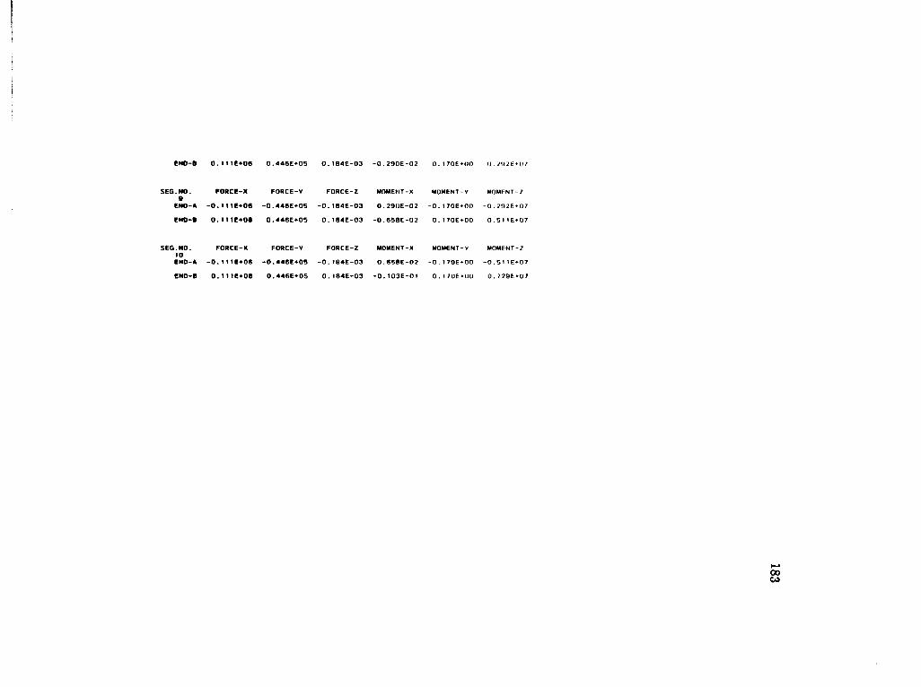
SEG.NO. 9 END-A
END-B
SEG.NO. 10 END-A
END-B
00 CO
0.446E+05 0.t04E-O3 -0.290E-02 0.170E+00 0.292E+U/
FORCE-X FORCE-V FORCE-Z
-O.ltfE^OS -0.446E+05 -0.184E-03
0.111E+08 0.446E+05 0.184E-03
MOMEMT-X MOMENT-V MOMENT-Z
0.29UE-02 -0.170E+00 -0.292E+07
-O.650E-O2 0.170E+00 0.511E+07
FORCE-X FORCE-V FORCE-Z MOMENT-X
-0.1ME+06 -0.446E*05 -O.!04E-O3 O.650E-O2
o.niioe 0 . 446E*05 0 . 184E-03 -0.103E-0I
MOMENT-V MOMENT-Z
-0.170E*00 -0.51}E*Q7
0. 1706*00 0.729E + 07

MEMBER 2 •••••••••«••
LOAD INCREMENT 80 • • • • • • • • • • • • • • • • • • A
>>> DISPLACEMENTS <<<
JOINT NO. 12 OISPL.-X OISPL.-0.OOOE+OO 0.OOOE+O
OISPL.-Z 0,OOOE+OO
ROTATION-X 0.OOOE *00
ROTA TION-V ROTATION-Z 0.OOOE+OO O.OOOE+OO
JOINT NO. 13
DISPL.-X OISPL.-0.I54E-01 -0.377E-C
DISPL.-Z -0. J 78E-10
ROTATION-X -0.175E-1I
ROTATION-V ROTATION-Z -0.226E-10 -0.150E-02
JOINT NO. 14
DISPL.-X DISPL. 0.574E-01 -0.814E-
OISPL.-Z -0.667E-10
ROTATION-X -0.321E-11
ROTATION-V ROTATION-Z -0.442E-10 -0.270E-02
JOINT NO. 15
OISPL.-X DISPL. 0.121E+00 -0.13 IE-
OISPL.-Z -0.141E-09
ROTATION-X -0.439E-1L
ROTATION-V ROTATION-Z -0.647E-10 -0.362E-02
JOINT NO. 16 DISPL.-X 01SPL. 0. 199E+00 -0.184E-
DISPL.-Z -0.234E-09
ROTATION-X -0.531E-\1
ROTATION-V - 0.041E-10 ROTATION-Z -0.429E-02
JOINT NO. 17
DISPL.-X DISPL. 0.2B9E+00 -0.240E-
OISPL.-Z -0.342E-09
ROTATION-X -O.590E-1I
ROTATION-V -0.I03E-09
ROTATION-Z -0.474E-0?
JOINT NO. 18
OISPL.-X OISPL. 0.386E+00 -0.296E-
OISPL.-Z -0.459E-09
ROTATION-X -0.641E-11
ROTATION-V -0. 1 21E-09
ROTATION-Z -0.501E-02
JOINT NO. 19
DISPL.-X DISPL 0.487E+00 -0.351E
.-V -01
DISPL.-Z -0.582E-09
ROTATION-X -0.661E-11
ROTATION-V -0.139E-09
ROTATION-Z -0.512E-02
JOINT NO. 20
DISPL.-X DI'.vP'-0.58BE+00 -O./r/E
. -V - 0 1
DISPL.-Z -0.705E-09
ROTATION-X -0.657E-11
ROTATION-V -0. 157E-09
ROTATION-Z -0.505E-02
JOINT NO. 2 1
DISPL.-X JISPL 0.686E+00 -0.462E
. -V - 0 1
OISPL.-Z -0.824E-09
ROTATION-X -0.630E-1y
ROTATION-V -0.175E-09
ROTATION-7 -O.402E-O?
JOINT NO. 2 2
OISPL.-X DISPL 0.7 77E + 00 -0.518E
. -V -01 OISPL.-Z -0.935E-09
ROTATION-X -0.578E-11
ROTAT XON-V -0.193E-09
ROTATION-Z -0.44 1F-0?
*>> FORCES
00

185

O.129E+O0 -0.118E+07 -0.184E-03 0.264E-02 -0.232E+00
SEG.NO. FORCC-X FORCE-Y FORCE-Z 9 END-A -0.129E+06 0.M8E + O7 O.104E-O3
END-B 0.129E*0« -0.MBE*07 -0.1B4E-03
MOMENT-*
-0.264E-02
0.646E-02
MOMENT-V
0.232E• 00
-0.232E»00
SEG.NO. FORCE-X FORCE-V FORCE-Z MOMENT-X MOMENT-V 10 END-A -0.129E+06 0.119E+07 0.1B4E-03 -0.646E-02 0.232E+00
EHD-B 0.129E+06 -0.1!8E*07 -0.184E-03 0.103E-01 -0.232E*00
(J . ?36E*07
MOMENT-?
0.236E + 0 7
0.503E*0?
MOMENT-2
0.503E+07
0 . 7 70E + 07
00 o>

MEMBER 3 ••••••••••••
LOAO INCREMENT 00
>>> DISPLACEMENTS <<<
JOINT NO. 23
OISPL.-X 0. 746E+00
OISPL.-V 0.255E-01
DISPL.-Z 0. 135E-08
ROTATION-X o.B08E-i y
ROT ATION-V 0.y99E-09
ROT AT ION-Z -0.374E-02
JOINT NO. 24
OISPL.-X 0.?54E*00
OISPL.-V -0.629E-01
DISPL.-Z -0.353E-0B
ROTATION-* 0.648E-11
ROTATION-V 0.101E-09
ROTATION-Z -0.163E-02
JOINT NO. 2S OISPL.-X 0.758E+00
OISPL.-V -0.904E-01
DISPL.-Z -0.574E-08
ROTATION-X 0 . 494E- 1 1
ROTAT tON-V 0.3 7 3E- H)
ROT ATION-Z - 0 . 104F.-03
JOINT NO. 26
D1SPL.-X 0.761E+00
OISPL.-V -0.757E-01
OISPL.-Z -0.63BE-0B
ROTATION-X 0.344E-11
ROTATION-V 0.621E-I1
ROTAT!ON-Z 0.H76E-03
JOINT NO. 27
OISPL.-X 0.761E+00
OISPL.-V -0.366E-01
OISPL.-Z -0.647E-08
ROTATION-X 0.215E-11
ROTATION-V 0.358E-11
ROT ATION-Z 0. 137E-0?
JOINT NO. 2B OISPL.-X
0.760E*00 DISPL.-V 0.118E-01
DISPL.-Z -0.672E-08
ROTATION-X 0 . 1 29E-11
ROTATION-V 0. 1 15E-10
ROTA TION-Z 0. 146E-02
JOINT NO. 29
OISPL.-X 0.760E+00
DISPL.-V 0.S90E-01
DISPL.-Z -0.725E-08
ROTATION-X 0.324E-12
ROTATION-V 0.194E-1U
ROTATION-Z 0. 128E-02
JOINT NO. 30
OISPL.-X 0.760E+00
DISPL.-V 0.932E-0I
DISPL.-Z -0.784E-08
ROTATION-X -0.107E-11
ROTATION-V 0. 1 1 1E-10
ROT ATION-7 0.667E-03
JOINT NO. 31 OISPL.-X 0.763E+00
OISPL.-V 0.985E-01
OISPL.-Z -0.766E-08
ROTATION-X -0.259E-11
ROTATION-v -0.2B4E-10
ROTATtON-Z -0.457E-03
JOINT NO. 32
OISPL.-X 0.769E+00
OISPL.-V 0.566E-01
DISPL.-Z -0.569E-08
ROTATION-X -0.415E-11
ROTATION-V -n.9f>?F- 10
ROT AT(ON-Z - O .
JOINT NO. 33
DISPL.-X 0.777E+00
DISPL.-V -0.51BE-01
DISPL.-Z -0.935E-09
ROTATION-X -0.578E-11
ROTATION-V -O.193F-09
ROT AT[ON- Z -0.441E-0?
>>> FORCES <<<

FORCE-X
0.12BC+0B
-0.128E+06
FORCE-X
0. 1296*00
-0.1296*06
FORCE-X
0.129E*06
-0.1296*06
FORCE-X
0.129E+0B
-0.129E*06
FORCE-X
0.129E+06
-0.129E+06
SEG.NO. 1 END-A
ENO-B
SEG.NO. 2
END-A
ENO-B
SEG.NO. 3 END-A
END-B
SEG.NO. 4 ENO-A
ENO-B
SEG.NO. S END-A
END-B
SEG.NO. 6 END-A
ENO-B
SEG.NO. 7 END-A
END-B
SEG.NO. 8 ENO-A
FORCE-X
0. 1296*06
-0.129E+06
FORCE-X
0.t296*06
-0.129E+06
FORCE-X
0. 129E*0R
FORCE-V
-0.4466*05 0.4466*05
FORCE-V
-0.446E*05
0.4466*05
FORCE-V
-0.446E*05
0.4466*05
FORCE-V
-0.446E*05
0.4466*05
FORCE-V
-0.446E+05
0.4466*05
FORCE-V
-0.446E+05
0.4466*05
FORCE-V
-0.4466*05
0.4466*05
FORCE-V
-0.4466*05
FORCE-Z
-0.1846-03
0. 1846-03
FORCE-Z
-0.184E-03
0. 1846-03
FORCE-Z
-0.104E-O3
0. 1846-03
FORCE-Z
-0.1846-03
0.1846-03
FORCE-Z
-0.184E-03
0. I85E-03
FORCE-Z
-0.184E-03
0.185E-03
FORCE-Z
-0.105E-O3
0. 1056-03
FORCE-Z
-n. 1856-03
MOMENT-X
0. 103E-01
-0.103E-01
MOMENT-X
0.103E-01
-0.1036-01
MOMENT-X
0.103E-01
-0.103E-01
M0M6NT-X
0. 1036-01
-O.1036-01
MOMENT-X
0. 1036-01
-0.I03E-01
MOMENT-X
0.1036-01
-0.103E-01
MOMENT-X
0.103E-01
-0.103F-01
MOMENT-X
o. ?o:u (11
MOMENT-V
-0.1706*00
0. 1766*00
M0M6NT-V
-0.176E+00
0.182E+00
MOMENT-V
-0.1826*00 0. 1 886 *00
MOMENT-V
-0. 1086*00 0 . 1956*00
MOMENT-Y
-n.195E •00
0.20tE*00
MOMENT-V
-0.201E *00 0.2076*00
MOMENT-V
-0.2076*00
0.2136*00
MOMfNT-V
-I) . / 1 M • (HI
MOMENT-Z
0 . 7296*07
0.5806*07
M0M6NT-Z
0.5806*07
0.430E+07
MOMENT-Z
0.4306*07
0 . 2806*07
MOMENT-Z
-0.2806*07
0. 110E»07
M0M6NT-Z
-0. 1 306*07
-0.?026*06
MOMENT-Z
0.2026*06
-0.170E*07
M0M6NT-?
o. T ;OE*O/
-0. 370FM17
MOMFNl /
I) < .'<»F * (1 / 00 00

CND-B -0.129E+06 0.104E-O3 -0.103E-01
SEQ.NO. 9 END-A
FOUCE-X FORCE-V
0.129E+06 -0.446E*05
ENO-B -0.129E+06
FORCE-Z
-0.184E-03
0. 184E-03
MOMENT-X MOMENT-V
0.103E-01 -0.2I9E+00
FORCE-X FORCE-V FORCE-Z
0.129E+06 -0 . 446E*05 -0.1B4E-03
END-B -0.I29E+06 0.446E+05
SEG.NO. TO ENO-A
MOMENT-X MOMENT-V
0.103E-01 -0.226E+00
0.184E-03 -0.I03E-01 0.232E*00
O . 4 70F *0 7
MOMENT-Z
0 . 470E + 07
•0.620E + 0 7
MOMENT-Z
0.620E+07
0 . 7 70E + 07

THE PIER-BENT HAD A CONCRETE COMPRESSION FAILURE
IN MEMBER 2 IN SECTION f OF SEGMENT 1
IN LOAD INCREMENT 148 OF LOAO CASE 2
JUST BEFORE FAILURE • • • • • • • • • • • • • • • • • A *
MAX. COMPRESSIVE CONCRETE STRAINs-0.352E-02 OCCUREO IN LOAO CASE = 2 OCCURED IN INCREMENT = 145 OCCURED IN MEMBER = 2 OCCUREO IN SEGMENT - l OCCURED IN SECTION = 1
MAX. TENSILE STEEL STRAIN: OCCURED IN LOAD CASE OCCUREO IN INCREMENT OCCURED IN MEMBER OCCURED IN SEGMENT OCCUREO IN SECTION
CD o

I
•• FORCES AND DISPLACEMENTS PREVIOUS TO FAILURE ••
CD

MEMBER 1
LOAD INCREMENT MS ••••••••••••••a****
»> DISPLACEMENTS <<<
OtSPL.-X O.OOOE-OO
OISPL.-V 0.000E+00
oisPL.-r 0.OOOE+OO
ROTATION-X 0.000E* 00
ROTATION-V ROTATION-2 0.OOOE •00 0.OOOE »00
JOINT NO. 2
DISPL.-X 0.35BE-01
DISPL.-v 0. 143E-01
OISPL.-Z 0.430E-10
ROTATION-X 0.432E-t t
ROTATION-V ROTATION-2 O.460E-1O -0.331E-02
JOINT NO. 3 DISPL.-X 0.1256*00
OISPL.-V 0.230E-01
OISPL.-Z 0.164E-09
ROTATION-X 0.796E-11
ROTATION-V 0.907F-10
ROTATION-Z -0.561E-02
JOINT NO. 4
DISPL.-X 0.Z55E+00
DISPL.-V 0.298E-0t
OISPL.-Z 0.345E-09
ROTATION-X 0. f JOE-10
ROTATION-V 0.J33E-09
ROT ATION-Z -0. 74 IE-02
JOINT NO. 5
DISPL.-X 0.416E+00
DISPL.-V 0.349E-01
OISPL.-Z 0.573E-09
ROTATION-X 0. I33E-10
ROTATION-V 0. 175E-09
ROTATION-Z -0.075E-O2
JOINT NO. 6
DISPL.-X 0.599E+00
OISPL.-V 0.30IE-01 OISPL.-Z O.037E-O9
ROTATION-X 0.151E-10
ROTATION-V 0.217E-09
ROT ATION-2 -0.9H4E-02
JOINT NO. 7
DISPL.-X 0.795E+00
DISPL.-V 0.396E-01
DISPL.-Z 0. 1 12E-O0
ROTATION-X 0.163E-10
ROTATION-V 0.250E-O9
ROTATION-Z -0. 101E-01
JOINT NO. 6
DISPL.-X 0.996E+00
DISPL.-V 0.399E-0I
OISPL.-Z 0.142E-08
ROTATION-X 0.169E-10
ROTATION-V 0.307E-09
ROT AT ION-Z -0.101E-01
OISPL.-X 0.119E+0I
DISPL.-V 0.412E-01
OISPL.-Z 0.172E-0B
ROTATtON-X 0.167E-10
ROTATION-V 0.349E-09
ROTATION-Z -0.973E-02
JOINT NO. 10
01SPL.-X 0.130E+O1
DISPL.-V 0.442E-01
DISPL.-Z 0.201E-08
ROTATION-X 0.159E-10
ROTATION-V 0.390E-09
ROTATION Z • 0 . R90F •()?
JOINT NO. ! 1 DISPL.-X 0. 1S4E*01
DISPL.-V 0.4B9E-01
DISPL.-Z 0.220E-O8
ROTATION- X 0.145E- 10
ROT ATION-V 0.431E 09
R O T A T I O N - 2 0 . 7(jJE -02
>>> FORCES <<<
CD to
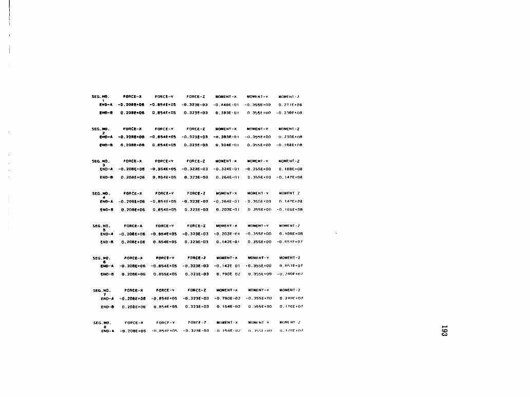
193

0.854E+05 0.323E-03 -0.491E-02 0.355E*00
SEG.NO. FORCE-X FORCE-V 9 ENO-A -0.208E+08 -0.854E«-05
ENO-B 0.20BE+06 0.854E+05
FORCE-2
-0.323E-03
MOMENT-X
0.491E-02
0.323E-03 -0. 1 !5E-01
MOMENT-V
-0.355E*00
0.355E+00
SEG.NO. FORCE-X FORCE-Y FORCE-Z MOMENT-X MOMENT-Y 10 END-A -0.208E+06 -O.054E+O5 -0.323E-03 0.115E-0! -0.355E*00
ENO-8 0.20BE+06 0.854E+0S 0.323E-03 -0.181E-01 0.355E»00
o.=;niE«-o7
MOMENT-2
•0.581 E + 07
0.992E *07
MOMENT-Z
• 0.992E+07
0. 140E *08

MEMBER 2 ••••••••••••
LOAD INCREMENT MB
>>> DISPLACEMENTS <<<
JOINT NO. 12
DISPL.-X D1SPL.-V O.OOOE+OO 0.OOOE+OO
OISPL.-Z O.OOOE+OO
ROTATION-* O.OOOE+OO
ROTATION-V ROT ATION-Z 0.000E *00 0.OOOE + OO
JOINT NO. 13
OlSPL.-X OlSPL.-V 0.365E-01 -0.I6BE-02
OISPL.-Z -0.351E-10
ROTATION-X -0.346E-11
ROT ATION-V ROTATTON-Z -0.563E-10 -0.33BE-02
JOINT NO. 14
OlSPL.-X OlSPL.-V 0.129E+00 -0.428E-02
DISPL.-Z -0.129E-09
ROTATION-X -0.634E - 1 1
ROTATION-V ROT AT!ON-Z -0.10BE-09 -0.5B6E02
JOINT NO. 15
OlSPL.-X DISPL.-V 0.26SE+00 -0.812E-02
OISPL.-Z -0.269E-09
ROTATION-X -0.S63E-11
ROTAT ION-V ROT ATION-Z -0.1S6E 09 0.773E-02
JOINT NO. 16
OlSPL.-X OlSPL.-V 0.432E+00 -0.132E-01
OISPL.-Z -0.442E-09
ROTATION-X -O.104E-10
ROTATION-V -0.200E-09
ROTATION-Z -0.905E-02
JOINT NO. 17
DISPL.-X DISPL.-V 0.620E+00 -0.I93E-01
OISPL.-Z -0.640E-09
ROTATION-X -0.117E-10
ROTATION-V -0.240E-09
ROTATION-Z -0.9B7E-02
JOINT NO. 18
OlSPL.-X OlSPL.-V 0. 820E+00 -0.259E-01
DISPL.-Z -0.8S1E-09
ROTATtON-X -0.125E-10
ROTATION-V -0.277E-09
ROTATION-Z -0.103E-01
JOINT NO. 19
OlSPL.-X OlSPL.-V 0.103E+01 -0.325E-01
OISPL.-Z -0.107E-08
ROTATION-X -0.128E-10
ROTATION-V -0.314E-09
ROTATION-2 -0. I04E-01
JOINT NO. 20
OlSPL.-X DISPL.-V 0.123E+01 -0.390E-01
DISPL.-Z -0.I29E-08
ROTATION-X -0.128E-10
ROTATION-V -0.350E-09
ROTATION-Z -0.102E-01
JOINT NO. 21 DISPL.-X OlSPL.-V
0.143E+01 -0.456E-01 OISPL.-Z
-0.150E-08 ROTATION-X -0.124E-10
ROTATI0N-V O.307E 09
ROTATION-Z -0.972r.-02
JOINT NO. 22 OlSPL.-X OlSPL.-V
0.161E+01 -0.515E-01 OlSPL.-Z
-0.17OE-O0 ROTATION-X -0.115E-10
ROTATION-V -0.428E-09
ROTATION-Z •0.879E-0?
>>> FORCES «<

- - o
- - o
- -
o
- z
3J
-m
rn • •
O ~
961

0.2276*06 -0.122E+07 -0.323E-03 0.442E-02
SEG.NO. FORCE-X 9 ENO-A -0.227E+06
END-B 0.227E*06
FORCE-V
0. 122E+07
-0.122E*07 -0.323E-03
FORCE-Z MOMENT-X
0.323E-03 -0.442E-02
0.112E-01
SEG.NO. FORCE-X FORCE-V FORCE-2 MOMENT-X 10 END-A -0.227E+06 0.122E+07 0.323E-03 -0.M2E-01
ENO-8 0.227E*06 -0.122E*07 -0.323E-03 0.1S1E-01
0.464E+00
MOMENT- V
0.464E+00
•0.464E+00
MOMENT-V
0.464E+00
•0.464E* 00
0 . 525E + 07
MOMENT-Z
0.5 25E *0 7
0.997E *07
MOMENT-Z
0.997E*07
0. T 47E + 08

MEMBER 3 ••••••••••••
LOAD INCREMENT US •••••••••••••••••••
»> DISPLACEMENTS <<<
JOINT NO. 23
DISPL.-X 0. 154E+01
OISPL.-V 0.4B9E-01
OISPL.-Z 0.22BE-0B
ROTATION-X 0.145E-10
ROTATION-V 0.43 1E-09
ROTATION- Z -0.763E-02
JOINT NO. 24
OISPL.-X 0.156E+0I
DISPL.-V -0. I30E+00
DISPL.-Z -0.792E-0B
ROTATION-X 0. 1 i4E-in
ROTATION-V 0 . 202E-09
ROTATION-Z -0.327E-02
JOINT NO. 25
OISPL.-X 0. 157E+01
OISPL.-V -0.183E+00
OISPL.-Z -0.124E-07
ROTATION-* 0 . 048E-11
ROTATION-V 0.739E-10
R0TAT10N-Z -0.865E-04
JOINT NO. 26
DISPL.-X 0. I58E+0I
DISPL.-V -0. I48E+00
DISPL.-Z -0.I35E-07
ROTATION-X 0.57 IE-I 1
ROTATION-V O. 9f>2F- J 1
ROT ATION-Z O. 197F-0^
JOINT NO. 27
OISPL.-X 0. 15BE*01
DISPL.-V -0.622E-01
DISPL.-Z -0.136E-07
ROTATION-X 0.335E-11
ROTATION-Y 0.369E-11
ROT AT ION-Z 0.296E-02
JOINT NO. 28 OISPL.-X 0. 158E*0t
DISPL.-V 0.422E-01
OISPL.-Z -0.140E-07
ROTATION-X 0. 101E-11
ROTATION-V O.204E-10
ROTATI ON-Z 0 . 3 lf»E - 0 2
JOINT NO. 29
OISPL.-X 0.157E+01
DISPL.-V 0. 145E+00
DISPL.-Z -0.150E-07
ROTATION-X 0.883E-13
ROTATION-V 0.367E-10
ROT AT ION-Z 0.2B1E-07
JOINT NO. 30
DISPL.-X 0.I58E+01
DISPL.-V 0. 222E+00
OISPL.-Z -0.161E-07
ROTATION-X -0.245E-11
ROTATION-V 0.208E-10
ROTATION-Z 0. 160E-02
JOINT NO. 31
DISPL.-X O.158E+01
DISPL.-V 0.240E+00
DISPL.-Z -0.15BE-07
ROTATION-X -0.525E-11
ROTATfON-V -0.536E- 10
ROTATION-Z -0.7O0E -03
JOINT NO. 32
DISPL.-X 0.160E+01
DISPL.-V 0.162E+00
DISPL.-2 -0.119E-07
ROTATJON-X -0.B1BE-1 1
ROTATION-V -0.194E-09
ROTATION-Z -0.416E-07
JOINT NO. 33
OISPL.-X 0.161E*01 DISPL.-V -0.515E-01
DISPL.-Z -0.170E-08
ROTATION-X -0.11BE - 10
ROTATION-V -0.47Bf-09
ROTATION-Z -n.H7nr•n?
>»> FORCES <<<
O 00

FORCE-X
0.227E*0B
-0.227E*0®
FORCE-X
0.227E+06
-0.227E-+0B
FORCE-X
0.227E-+06
-0.227E+06
FORCE-X
0.227E+0B
-0.227E+0B
FORCE-X
0.227E+06
-0.227E+06
SEC.NO. t
END-A
ENO-9
SEG.NO. 2
ENO-A
END-B
SEG.NO. 3 ENO-A
ENO-6
SEG.NO. 4 ENO-A
ENO-8
SEG.NO. 5 END-A
END-B
SEG.NO. 6 END-A
END-B
SEG.NO. 7 END-A
ENO-B
SEG.NO. 6 END-A
FORCE-X
0.227E+06
-0.227E+0B
FORCE-X
0. 227E+06
-0.227E*06
FORCE-X
0.227E+06
FORCE-V
-0.B54E+05
O.B55E+05
FORCE-V
-0.B55E+05
0. 855E+05
FORCE-V
-0.855E+05
0.855E+Q5
FORCE-V
-0.B55E+05
0.855E*05
FORCE-V
-0.B55E+05
0 . 8 5 5 6 + 0 5
FORCE-V
-0.855E+05
0.B55E+05
FORCE-V
-0.855E+05
0.855E+05
FORCE-V
-0 . 8*iSE*05
FORCE-Z
-0.323E-03
0.324E-03
FORCE-Z
-0.323E-03
0.3236-03
FORCE-Z
-0.3236-03
0.323E-03
FORCE-Z
-0.323E-03
0.324E-03
FORCE-Z
-0.324E-03
0.324E-03
FORCE-Z
-0.323E-03
0.324E-03
FORCE-Z
-0.324E-03
0.324E-03
FORCE-Z
-0.324E-03
MOMENT-X
0.1B1E-01
-0. 181E-01
MOMENT-X
0.1B1E-01
-0.181E-01
MOMENT-X
0. 1816-01 -0.1816-01
MOMENT-X
0. 1B1E-01
-0.181E-01
MOMENT-X
0. 18 tE-01 -0.181E-01
MOMENT-X
0.1B1E-01
-0.181E-01
MOMENT-X
0. 1B1E-01
-0.1816-01
MOMENT-X
0 . 1 8 1 E - 0 1
MOMENT-V
-0.355E+00
0.3666*00
MOMENT-V
-0.3666+00
0.377E+00
MOMENT-V
-0.3776*00
0.3006*00
MOMENT-V
-0.388E+00
0.390E*00
MOMENT-V
-0.3986+00
0.409E+00
MOMENT-V
-0.409E+00
0.4206+00
M0M6NT-V
-0.420E+00
0.431E+00
MOMENT V
-0 . A lit « Of)
MOMENT-Z
-0. 140E+08
0. 1 12E+0B
MOMENT-Z
-0.112E+0B
0 . 8296 + 07
M0M6NT-Z
-0.829E+07
0.542E+07
MOMENT-Z
-0.542E+07
0.254E+07
MOMENT-Z
-0.254E+07
-0.327E+06
MOMENT-Z
0.3276+06
-0.320E+07
MOMENT-Z
0.320E + 0 7
-0.607E+07
M O M F N T - 7
n f . n / F « u ;

END-B -0.227E+08 0.B55E+05 0.323E-03 -0.1B1E-0I 0 .442E+00 -0 .B94E+07
SEG.NQ. 9 END-A
END-B -0.227E+O0
FORCE-X FORCE-V FORCE-Z
0.227E+06 -0.B55E+05 -0.323E-03
0.B55E+05
MOMENT-X MOMENT-V
0 .1B1E-0 I -0 .442E+00
0 .323E-03 -0 . tB1E-01
MOMENT-Z
O .B94E+07
0 .453E+00 -0 .11BE+08
SEG.NO. 10 END-A
FORCE-X FORCE-Y FORCE-Z
0.227E+06 -0.S55E+05 -0.323E-03
END-B -0.227E*O0 0.8S4E+05
•dOMENT-X MOMENT-Y
0 .1B1E-01 -0 .453E+00
0 .323E-03 -0 .1B1E-01 0 .464E+00
MOMENT-Z
0 . t 18E*0B
-O . 1 47E*08
to o o

201
REFERENCES
ACI 318-83, Building Code Requirements for Reinforced Concrete, American Concrete Institute, Detroit, 1983.
Adams, John, "Non-linear Behavior of Steel Frames," unpublished Ph. D. Dissertation, Massachussets Institute of Technology, June 1973.
Breen, J. E., and Ferguson, P. M., "The Restrained Long Concrete Column as a Part of a Rectangular Frame," ACI Journal, Proceedings, Vol. 61, No. 5, Mav 1964, pp. 563-587.
Broms, B., and Viest, I. M., "Design of Long Reinforced Concrete Columns," Journal of the Structural Division, ASCE, Vol. 84, No. ST 4, Proc. Paper 1694, Julv 1958, pp. 1694-1-1694-28.
Broms, B., and Viest, I. M., "Ultimate Strength Analysis of Long Hinged Reinforced Concrete Columns," Journal of the Structural Division, ASCE, Vol. 84, No. ST 1. Proc. Paper 1510, January 1958, pp. 1510-1-1510-38.
Broms, B., and Viest, I. M., "Ultimate Strength Analysis of Long Restrained Reinforced Concrete Columns," Journal of the Structural Division, ASCE, Vol. 84, No. ST 3, Proc. Paper 1635, May 1958, pp. 1635-1-1635-30.
Chang, W. F., and Ferguson, P. M., "Long Hinged Reinforced Concrete Columns." Proceedings of the American Concrete Institute, Vol. 60, January 1963, pp. 1-25.
Chovichien, Vinit, Gutzwiller, M. J., and Lee, R. H., "Analysis of Reinforced Concrete Columns tinder Sustained Load," ACI Journal, Proceedings Vol. 70, No. 10, October 1973, pp. 692-699.
Diaz, Manuel A., "Evaluation of Approximate Slenderness Procedures for Nonlinear Analysis of Concrete and Steel FVames," Ph. D. Dissertation, University of Texas at Austin, 1984, 233 p.
Ford, Jaines S., "Behavior of Concrete Columns in Unbraced Multipanel Frames," Ph. D. Dissertation, The University of Texas at Austin, December 1977.
Gilliam, T. E., Yamamoto, Y., Poston, R. W., and Breen, J. E., "Verification of Analysis Programs for Solid and Hollow Concrete Bridge Piers," Research Report 254-1, Center of Transportation Research, The University of Texas, Austin, Texas, September 1983.

202
Hognestad, E., "A Study of Combined Bending and Axial Load in Reinforced Concrete Members," Bulletin No. 339, University of Illinois, Engineering Experiment Station, Nov., 1951.
MacGregor, J. G., Breen, J. E., and Pfrang, E. 0., "Design of Slender Concrete Columns," ACI Journal, Proceedings Vol. 67, No. 1, January 1970, pp. 6-2S.
MacGregor, James G., and Hage, Sven E., "Stability Analysis and Design of Concrete Frames," Journal of The Structural Division, Proceedings of ASCE, Vol. 103. No. ST 10, October 1977, pp. 1953-1970.
MacKinnon, D. H., "Reinforced Concrete Columns in Unbraced Frames," M. Sc. Thesis, University of Waterloo, Waterloo, Ontario, 1980.
Notes on ACI 318-83, Building Code Requirements for Reinforced Concrete with Design Applications, Portland Cement Association, Skokie, Illinois, 1984.
Pagay, Shriniwas N., Ferguson, Phil M., and Breen, John E., "Importance of Beam Properties on Concrete Column Behavior," ACI Journal, Proceedings Vol. 67, No. 10, Oct. 1970, pp. 808-815.
Pfrang, Edward O., and Siess, Chester P., "Behavior of Restrained Reinforced Concrete Columns," Journal of the Structural Division, Proceedings of ASCE, Vol. 90, No. ST 5, October 1964, pp. 113-136.
Poston, R. W., Diaz, M., Breen, J. E. and Roesset, J. M., "Design of Slender, Nonprismatic, and Hollow Concrete Bridge Piers," Research Report 254-2F, Center of Transportation Research, The University of Texas at Austin, April 1983.
Saenz, Luis P., and Martin, Ignacio, "Test of Reinforced Concrete Columns with High Slenderness Ratios," ACI Journal Proceedings, Vol. 60, No. 5, May 1963, pp. 589-615.