
INFORMATION MODEL FOR MACHINE-TOOL-PERFORMANCE …
34
INFORMATION MODEL FOR MACHINE-TOOL-PERFORMANCE TESTS Y. Tina Lee Manufacturing Systems Integration Division National Institute of Standards and Technology Gaithersburg, MD 20899-8260 Johannes A. Soons M. Alkan Donmez Automated Production Technology Division National Institute of Standards and Technology Gaithersburg, MD 20899-8220 ABSTRACT This report specifies an information model of machine-tool-performance tests in the EXPRESS [1] language. The information model provides a mechanism capable of describing the properties and results of machine-tool-performance tests. The objective of the information model is a standardized, computer- interpretable representation that allows for efficient archiving and exchange of performance test data throughout the life cycle of the machine. The report also demonstrates the implementation of the information model using three different implementation methods. Keywords: data exchange, EXPRESS language, information model, machine performance test, machine tools DISCLAIMER Certain commercial equipment, instruments, or materials are identified in this paper in order to facilitate understanding. Such identification does not imply recommendation or endorsement by the National Institute of Standards and Technology, nor does it imply that the materials or equipment identified are necessarily the best available for the purpose.
Transcript of INFORMATION MODEL FOR MACHINE-TOOL-PERFORMANCE …

INFORMATION MODEL FOR
MACHINE-TOOL-PERFORMANCE TESTS
Y. Tina LeeManufacturing Systems Integration Division
National Institute of Standards and TechnologyGaithersburg, MD 20899-8260
Johannes A. SoonsM. Alkan Donmez
Automated Production Technology DivisionNational Institute of Standards and Technology
Gaithersburg, MD 20899-8220
ABSTRACTThis report specifies an information model of machine-tool-performance tests in the EXPRESS [1]language. The information model provides a mechanism capable of describing the properties and results ofmachine-tool-performance tests. The objective of the information model is a standardized, computer-interpretable representation that allows for efficient archiving and exchange of performance test datathroughout the life cycle of the machine. The report also demonstrates the implementation of theinformation model using three different implementation methods.
Keywords: data exchange, EXPRESS language, information model, machine performance test, machinetools
DISCLAIMERCertain commercial equipment, instruments, or materials are identified in this paper in order to facilitateunderstanding. Such identification does not imply recommendation or endorsement by the National Instituteof Standards and Technology, nor does it imply that the materials or equipment identified are necessarily thebest available for the purpose.

Table of Contents
1. INTRODUCTION 1
1.1 Objective 11.2 Problem Statement 11.3 Scope 11.4 Modeling Language and Implementation Methods 2
2. INFORMATION MODEL 3
2.1 Structure of Data Requirements 32.2 EXPRESS Information Model 6
2.2.1 Entity Definitions 62.2.2 Type Definition 16
3. IMPLEMENTATION SAMPLES 19
3.1 ISO 10303 Part 21 Exchange Structure 193.2 XML Document 213.3 Relational Tables 24
4. USE OF THE INFORMATION MODEL 26
5. CONCLUSION 26
APPENDIX A EXPRESS KEYWORDS 27
REFERENCES29

1
1. Introduction
1.1 Objective
This report specifies an information model of machine-tool-performance tests in the EXPRESS modelinglanguage [1]. It is based on the information model described in the Data Specification for Machine ToolPerformance Tests, Version 2.3e [2]. The objective of the information model is a standardized, computer-interpretable representation that allows for efficient archiving and exchange of performance test datathroughout the life cycle of a machine tool. It serves as a basis for generating database schemas, databasecalls, and neutral file formats. Performance test data of machine tools is used for machine acceptance,performance tracking, software compensation, and to evaluate the capability of a machine to manufacturea part to specified tolerances.
The information model specifies the test procedure, the test conditions, the used equipment, themeasurement set-up, and the test results. It can be used to describe the properties and results of aperformance test at a level close to the raw measurement data. As such, the information elements enablethe user to re-create the set-up, equipment settings, and measurement procedure. The model captures keyinformation on the large variety of possible test set-ups and measurement procedures, which is essential forthe interpretation of the test results. A subset of the specification can be used to summarize the test,focusing on performance parameters that are estimated from the measurement results.
The information model addresses machine tool properties that are verified by performance tests. Itcomplements machine-tool-specification data that is not tested, e.g., the machine configuration, theworkspace, weight and size of the machine, tool holder standard, auxiliary devices, etc. [3].
The information model is intended to serve as the starting point for a future, standardized representation.The model is expected to change and grow based on further review and future implementation experience.
1.2 Problem Statement
Today’s manufacturing industry greatly relies on computer technology to support activities throughout aproduct’s life cycle. Efficient and distributed access to the performance data of machine tools is importantin manufacturing. The results of performance tests are used for machine acceptance, predictivemaintenance, error compensation, and to evaluate the capability of a machine to manufacture parts tospecified tolerances. A critical enabler to the efficient interchange and storage of performance data is aunified information model for the results and properties of performance tests.
Currently, there is no agreed-upon mechanism for representing the properties and results of machine-tool-performance tests [2]. There exists a variety of software packages for the performance evaluation ofmachine tools. They usually have been developed by the manufacturer of a particular measurement device,such as a laser interferometer or a ball bar, and are tailored to that particular instrument. The softwarepackages employ different data models and store the data in files using vendor-specific formats. Thiscomplicates data exchange, data storage in databases, and use of the data by third-party software.Furthermore, the stored data is often limited to the data required to produce the graphs and numbersspecified in the various standards for machine-tool-performance evaluation (e.g., [4,5,6]). This may resultin inefficient access or even loss of the additional data that is required for other applications, such as virtual

2
machining and software error compensation. Finally, not all tests described in the standards are addressedby existing software for machine tool testing. This is often the case for tests that require genericequipment, such as displacement indicators. Users have created their own “in-house” methods, often usingspreadsheets, to store the properties and results of these tests, often on an ad-hoc basis.
1.3 Scope
This specification supports the majority of instrumented, machine-tool-performance tests defined in theAmerican [4,5] and ISO [6] standards:
a) Positioning accuracy and repeatability of linear and angular positioning axes.b) Geometric errors of linear and angular positioning axes.c) Spindle axis of rotation.d) Machine thermal tests: ETVE, spindle, axis, and composite.e) Critical alignments: parallelism and squareness of machine axes.f) Circular contouring tests.g) Diagonal displacement tests.h) Subsystem repeatability (tool change, turret, gage line, and pallet repeatability).i) Compliance and hysteresis.
Of these tests the following information is described:
a) Date and time of the test.b) Identification of the machine tool on which the test was performed.c) Indication as to why the test was performed.d) The operator who performed the test.e) The machine status and environmental conditions during the test.f) The standard in which the test is defined.g) The equipment and software used to perform the test.h) The measurement set-up and operating parameters.i) The raw measurement data.j) The calculated performance parameters.
1.4 Modeling Language and Implementation Methods
The information model presented in this report is in the EXPRESS language. The EXPRESS modelinglanguage [1] was developed as part of the International Organization for Standardization (ISO), mostcommonly known as the 10303 Standard for the Exchange of Product Model Data (STEP) [7]. STEP is aninternational standard, the result of an effort to develop a mechanism for digitally representing the physicaland functional characteristics of a product throughout the product’s life cycle. STEP includes informationmodels and mechanisms for representing the models and related data. EXPRESS is a formally specifiedstructured language. EXPRESS models have an object-oriented flavor. The reason EXPRESS is chosenhere is three-fold: EXPRESS is primarily an information modeling language, EXPRESS is a textualrepresentation that permits machine processing of the specification, and EXPRESS consists of languageelements that allow an unambiguous object definition and specification of constraints on the objects defined.

3
An information model provides a sharable, stable, and organized structure of information requirements. Itis developed to preserve independence from both usage and implementation. Implementation independenceallows users to select their implementation methods. The selection of an implementation method is heavilydependent on the target environment where the application system resides. Currently, the implementationmethods used by the manufacturing community include:
1) data transfer via a working form, which is a structured, in-memory representation of data2) data transfer via an exchange file, which is a file with a predefined structure or format3) data transfer using a database management system [8]
STEP introduced the 10303 Exchange Structure, or the 10303-21, or the Part 21 file, as an implementationmethod for actual EXPRESS models [9]. A Part 21 file contains instances of the various entities definedby the EXPRESS information model. The Part 21 file format is just one of the implementation methodsthat implement the EXPRESS information models. Tools that support the implementation of EXPRESSinformation models are briefly described in Section 4.
2. Information Model
In this section, an EXPRESS information model for representing the properties and results of machine-tool-performance tests is presented. Subsection 2.1 describes the structure of data requirements. The schemais presented in detail in subsection 2.2. Appendix A contains the listing of EXPRESS keywords that areused in the schema.
2.1 Structure of Data Requirements
The information model presented in subsection 2.2 has been based on the “Data Specification for MachineTool Performance Tests, Version 2.3e”[2]. The large variety of addressed performance tests are classifiedinto four groups:
1) Circular: tests where error motions are measured at points on a circular path in the machineworkspace.
2) Line: tests where error motions are measured at points on a line in the space spanned bythe positioning axes of the machine (e.g., positioning accuracy, axis geometry,diagonal displacement accuracy, axis alignment, and thermal distortion caused byaxis motion).
3) Point: tests where error motions are measured at a single point in the space spanned by thepositioning axes of the machine (e.g., subsystem repeatability, spindle axis ofrotation, spindle thermal stability, and Environmental Temperature Variation Error).
4) Compliance: tests for the compliance and hysteresis of the machine under static loads.
The specifications for other performance tests, e.g., CNC performance tests, machining tests, and testsaddressing the measurement capabilities of a machine tool, are under development and will follow thestructure outlined below. Figure 1 shows the relationships among the major entities in the informationmodel. The figure is presented by EXPRESS-G1 [1], a graphical subset of the EXPRESS language. The 1 EXPRESS-G is represented by graphic symbols forming a diagram. The definitions of data types and schemas within a diagramare denoted by boxes which enclose the name of the item being defined. The relationships between the items are denoted by thelines joining the boxes. Differing line styles provide information on the kind of definition or relationships. For example, a
4
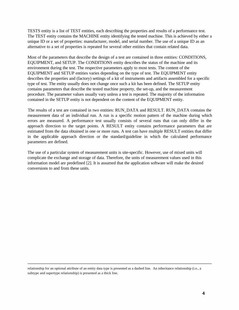
TESTS entity is a list of TEST entities, each describing the properties and results of a performance test.The TEST entity contains the MACHINE entity identifying the tested machine. This is achieved by either aunique ID or a set of properties: manufacturer, model, and serial number. The use of a unique ID as analternative to a set of properties is repeated for several other entities that contain related data.
Most of the parameters that describe the design of a test are contained in three entities: CONDITIONS,EQUIPMENT, and SETUP. The CONDITIONS entity describes the status of the machine and itsenvironment during the test. The respective parameters apply to most tests. The content of theEQUIPMENT and SETUP entities varies depending on the type of test. The EQUIPMENT entitydescribes the properties and (factory) settings of a kit of instruments and artifacts assembled for a specifictype of test. The entity usually does not change once such a kit has been defined. The SETUP entitycontains parameters that describe the tested machine property, the set-up, and the measurementprocedure. The parameter values usually vary unless a test is repeated. The majority of the informationcontained in the SETUP entity is not dependent on the content of the EQUIPMENT entity.
The results of a test are contained in two entities: RUN_DATA and RESULT. RUN_DATA contains themeasurement data of an individual run. A run is a specific motion pattern of the machine during whicherrors are measured. A performance test usually consists of several runs that can only differ in theapproach direction to the target points. A RESULT entity contains performance parameters that areestimated from the data obtained in one or more runs. A test can have multiple RESULT entities that differin the applicable approach direction or the standard/guideline in which the calculated performanceparameters are defined.
The use of a particular system of measurement units is site-specific. However, use of mixed units willcomplicate the exchange and storage of data. Therefore, the units of measurement values used in thisinformation model are predefined [2]. It is assumed that the application software will make the desiredconversions to and from these units.
relationship for an optional attribute of an entity data type is presented as a dashed line. An inheritance relationship (i.e., asubtype and supertype relationship) is presented as a thick line.

5

6
2.2 EXPRESS Information Model
This subsection describes the detailed information for the schema of machine-tool-performance tests. Theschema name is MACHINE_TOOL_PERFORMANCE_TESTS. An EXPRESS schema is composed ofdeclarations of types, entities, constraints, and their relationships. The concept of a type in EXPRESS isthe same as that of a data type in a standard programming language. It defines the kind of values that anobject may assume. Entities are the focal point of an EXPRESS information model. An entity declarationdescribes the information content of an object, as well as some of the constraints on the objects.
In EXPRESS language, a “remark” is used for documentation and is not significant as a language element.The character pair, “(” and “*”, is used to denote the start of an embedded remark, and the character pair,“*” and “)”, is used to denote its end. An embedded remark may appear between any two tokens. In thisreport, the documentation is presented as embedded remarks. Consequently, this entire report can be readinto an EXPRESS parser for further analysis.
*)
SCHEMA MACHINE_TOOL_PERFORMANCE_TESTS;
(*
2.2.1 Entity Definitions
The entities are formally defined in this subsection. The entities presented here are in the “top-down”order, i.e., primitive type definitions are presented last.
*)
ENTITY TESTS_DEF;TESTS: LIST [1:?] OF UNIQUE TEST_DEF;
END_ENTITY;
ENTITY TEST_DEF;ID: OPTIONAL STRING;TEST_CLASS: TEST_CLASS_DEF;DATE: DATE_DEF;TIME: OPTIONAL TIME_DEF;WHY: OPTIONAL WHY_DEF;MACHINE: MACHINE_DEF;CONDITIONS: OPTIONAL CONDITIONS_DEF;OPERATOR: OPTIONAL STRING;STANDARD: OPTIONAL STANDARD_DEF;EQUIPMENT: EQUIPMENT_DEF;SETUP: SETUP_DEF;RUN_DATA: OPTIONAL LIST [1:?] OF RUN_DATA_DEF;RESULT: OPTIONAL LIST [1:?] OF RESULT_DEF;COMMENT: OPTIONAL TEXT;
END_ENTITY;

7
ENTITY DATE_DEF;YYYY: INTEGER;MM: INTEGER;DD: INTEGER;
WHEREWR1: (YYYY >= 1900);
WR2: (1 <= MM) AND (MM <= 12);WR3: (1 <= DD) AND (DD <= 31);
END_ENTITY;
ENTITY TIME_DEF;HH: INTEGER;MM: INTEGER;SS: INTEGER;
WHEREWR1: (0 <= HH) AND (HH <= 24);
WR2: (0 <= MM) AND (MM <= 59);WR3: (0 <= SS) AND (SS <= 59);WR4: ((HH = 24) AND ((MM = 0) AND (SS = 0)));
END_ENTITY;
ENTITY MACHINE_DEF;ID : OPTIONAL STRING;MANUFACTURER: STRING;MACHINE_MODEL: STRING;SERIAL_NUMBER : STRING;LOCATION: OPTIONAL STRING;
END_ENTITY;
ENTITY CONDITIONS_DEF;CLAMPED_AXES: OPTIONAL LIST [1:?] OF AXIS_DEF;
COMPENSATION: OPTIONAL BOOLEAN;COMPENSATION_ID: OPTIONAL STRING;COOLANT: OPTIONAL BOOLEAN;DRIVE_STATUS: OPTIONAL DRIVE_STATUS_DEF;TEMP_ENVIRONMENT: OPTIONAL REAL;WARMUP: OPTIONAL BOOLEAN;WARMUP_DESCRIPTION: OPTIONAL STRING;
END_ENTITY;
ENTITY STANDARD_DEF;ORGANIZATION: STRING;STANDARD_NUMBER: STRING;NAME: OPTIONAL STRING;YEAR: INTEGER;TEST_NAME: OPTIONAL STRING;SECTION_NUMBER: OPTIONAL STRING;SECTION_NAME: OPTIONAL STRING;STATUS: OPTIONAL STANDARD_STATUS_DEF;
WHERE

8
WR1: (YEAR > 1900);END_ENTITY;
ENTITY EQUIPMENT_DEFSUPERTYPE OF (ONEOF (EQUIPMENT_CIRCULAR_DEF,
EQUIPMENT_LINE_DEF,EQUIPMENT_POINT_DEF,EQUIPMENT_COMPLIANCE_DEF));
ID: OPTIONAL STRING;COMPONENT: OPTIONAL LIST [1:?] OF COMPONENT_DEF;SOFTWARE: OPTIONAL SOFTWARE_DEF;RESOLUTION: OPTIONAL REAL;SAMPLE_RATE_RAW: OPTIONAL REAL;
END_ENTITY;
ENTITY COMPONENT_DEF;ID: OPTIONAL STRING;DESCRIPTION: OPTIONAL STRING;MANUFACTURER: STRING;COMPONENT_MODEL: STRING;SERIAL_NUMBER : STRING;CALIBRATION_DATE: OPTIONAL DATE_DEF;CALIBRATION_EXP_DATE: OPTIONAL DATE_DEF;CERTIFICATE_NUMBER: OPTIONAL STRING;CALIBRATION_ORGANIZATION: OPTIONAL STRING;
END_ENTITY;
ENTITY SOFTWARE_DEF;ID: OPTIONAL STRING;MANUFACTURER: STRING;NAME: STRING;VERSION_NUMBER: STRING;
END_ENTITY;
ENTITY SETUP_DEFSUPERTYPE OF (ONEOF (SETUP_CIRCULAR_DEF,
SETUP_LINE_DEF,SETUP_POINT_DEF,SETUP_COMPLIANCE_DEF));
END_ENTITY;
ENTITY RUN_DATA_DEFSUPERTYPE OF (ONEOF (RUN_DATA_CIRCULAR_DEF,
RUN_DATA_LINE_DEF,RUN_DATA_POINT_DEF,RUN_DATA_COMPLIANCE_DEF));
END_ENTITY;
ENTITY RESULT_DEF;STANDARD: STANDARD_DEF;

9
MEASURAND: OPTIONAL MEASURAND_POINT_DEF;PARAMETER: LIST [1:?] OF PARAMETER_DEF;
END_ENTITY;
ENTITY PARAMETER_DEF;NAME: STRING;VAL: REAL;APPROACH_DIRECTION: OPTIONAL APPROACH_DIRECTION_DEF;
END_ENTITY;
ENTITY EQUIPMENT_CIRCULAR_DEFSUPERTYPE OF (ONEOF(BALL_BAR_DEF,
DISK_DEF,GRID_ENCODER_DEF))
SUBTYPE OF (EQUIPMENT_DEF);EQUIPMENT_CLASS: EQUIPMENT_CLASS_CIRCULAR_DEF;ABSOLUTE: BOOLEAN;
FILTER_LS_CENTER: BOOLEAN;FILTER_LS_RADIUS: BOOLEAN;TEMP_REFERENCE_COMP: BOOLEAN;TEMP_REFERENCE_SENSOR: OPTIONAL LIST [1:?] OF TEMP_SENSOR_DEF;TEMP_REFERENCE_COEFFICIENT: REAL;
END_ENTITY;
ENTITY BALL_BAR_DEFSUBTYPE OF (EQUIPMENT_CIRCULAR_DEF);
CALIBRATOR: OPTIONAL BOOLEAN;END_ENTITY;
ENTITY DISK_DEFSUBTYPE OF (EQUIPMENT_CIRCULAR_DEF);
MACHINE_PROBE: BOOLEAN;INNER_CIRCLE: OPTIONAL BOOLEAN;
END_ENTITY;
ENTITY GRID_ENCODER_DEFSUBTYPE OF (EQUIPMENT_CIRCULAR_DEF);
END_ENTITY;
ENTITY SETUP_CIRCULAR_DEFSUPERTYPE OF (ONEOF(SETUP_CIRCULAR_STATIC_DEF,
SETUP_CIRCULAR_DYNAMIC_DEF))SUBTYPE OF (SETUP_DEF);
ID: OPTIONAL STRING;MEAS_MODE: MEAS_MODE_DEF;PLANE: PLANE_DEF;ROTARY_AXIS: OPTIONAL AXIS_DEF;CENTER: MACHINE_POSITION_DEF;TOOL_VECTOR: TOOL_VECTOR_DEF;SPINDLE_NUMBER: OPTIONAL INTEGER;

10
TURRET_NUMBER: OPTIONAL INTEGER;RADIUS_MACHINE: REAL;RADIUS_REFERENCE: REAL;INCLINATION: REAL;FEEDRATE: REAL;OVERSHOOT: OPTIONAL REAL;TEMP_MATERIAL_COMP: BOOLEAN;TEMP_MATERIAL_SENSOR: OPTIONAL LIST [1:?] OF TEMP_SENSOR_DEF;TEMP_MATERIAL_COEFFICIENT: OPTIONAL REAL;SAMPLES_AVERAGED: OPTIONAL INTEGER;POINT_MODE: POINT_MODE_CIRCULAR_DEF;INTERPOLATION: OPTIONAL INTERPOLATION_DEF;NC_PROGRAM_ID: OPTIONAL STRING;ALIGNMENT_METHOD: OPTIONAL ALIGNMENT_METHOD_DEF;ALIGNMENT_WHEN: OPTIONAL ALIGNMENT_WHEN_DEF;DATUM_WHEN: OPTIONAL DATUM_WHEN_DEF;PREVIOUS_TEST_ID: OPTIONAL STRING;
WHEREWR1: (TEMP_MATERIAL_COMP) AND (EXISTS(TEMP_MATERIAL_COEFFICIENT));
END_ENTITY;
ENTITY PLANE_DEF;X: AXIS_DEF;Y: AXIS_DEF;
END_ENTITY;
ENTITY SETUP_CIRCULAR_STATIC_DEFSUBTYPE OF (SETUP_CIRCULAR_DEF);
SETUP_STATIC: SETUP_STATIC_DEF;APPROACH_MODE: APPROACH_MODE_CIRCULAR_DEF;
END_ENTITY;
ENTITY SETUP_CIRCULAR_DYNAMIC_DEFSUBTYPE OF (SETUP_CIRCULAR_DEF);
SETUP_DYNAMIC: SETUP_DYNAMIC_DEF;CAM_SOFTWARE: OPTIONAL SOFTWARE_DEF;NC_CIRCULARITY: OPTIONAL REAL;
END_ENTITY;
ENTITY RUN_DATA_CIRCULAR_DEFSUBTYPE OF (RUN_DATA_DEF);
APPROACH_DIRECTION: APPROACH_DIRECTION_DEF;LS_CENTER_OFFSET_X: OPTIONAL REAL;LS_CENTER_OFFSET_Y: OPTIONAL REAL;LS_RADIUS_ERROR: OPTIONAL REAL;TEMP_REFERENCE: OPTIONAL LIST [1:?] OF TEMP_DATA_DEF;TEMP_MATERIAL: OPTIONAL LIST [1:?] OF TEMP_DATA_DEF;POINTS: LIST[1:?] OF REAL;
WHEREWR1: ((EQUIPMENT_CIRCULAR_DEF.FILTER_LS_CENTER) AND

11
(EXISTS (LS_CENTER_OFFSET_X) AND EXISTS (LS_CENTER_OFFSET_Y)));
WR2: ((EQUIPMENT_CIRCULAR_DEF.FILTER_LS_RADIUS) AND(EXISTS (LS_RADIUS_ERROR)));
END_ENTITY;
ENTITY EQUIPMENT_LINE_DEFSUBTYPE OF (EQUIPMENT_DEF);
EQUIPMENT_CLASS: EQUIPMENT_CLASS_LINE_DEF;FILTER_LS_SLOPE: OPTIONAL BOOLEAN;FILTER_LS_CENTER: OPTIONAL BOOLEAN;FILTER_OFFSET: BOOLEAN;TEMP_REFERENCE_COMP: OPTIONAL BOOLEAN;TEMP_REFERENCE_COEFFICIENT: OPTIONAL REAL;TEMP_REFERENCE_SENSOR: OPTIONAL LIST [1:?] OF TEMP_SENSOR_DEF;LASER_INTERFEROMETER: OPTIONAL LASER_INTERFEROMETER_DEF;TARGET_SHAPE: OPTIONAL TARGET_SHAPE_DEF;TARGET_DIAMETER: OPTIONAL REAL;
END_ENTITY;
ENTITY LASER_INTERFEROMETER_DEF;AIR_HUMIDITY_COMP: OPTIONAL BOOLEAN;AIR_PRESSURE_COMP: OPTIONAL BOOLEAN;DEADPATH_COMP: OPTIONAL BOOLEAN;VOL_COMP_METHOD: OPTIONAL VOL_COMP_METHOD_DEF;
END_ENTITY;
ENTITY SETUP_LINE_DEFSUPERTYPE OF (ONEOF (SETUP_LINE_STATIC_DEF,
SETUP_LINE_DYNAMIC_DEF))SUBTYPE OF (SETUP_DEF);
ID: OPTIONAL STRING; MEAS_MODE: MEAS_MODE_DEF;
MEASURAND: MEASURAND_LINE_DEF;MEAS_METHOD: MEAS_METHOD_DEF;AXIS: OPTIONAL AXIS_DEF;SENSITIVE_DIRECTION: OPTIONAL SENSITIVE_DIRECTION_DEF;START_POINT: MACHINE_POSITION_DEF;END_POINT: OPTIONAL MACHINE_POSITION_DEF;TOOL_VECTOR: TOOL_VECTOR_DEF;SPINDLE_NUMBER: OPTIONAL INTEGER;TURRET_NUMBER: OPTIONAL INTEGER;FEEDRATE: REAL;DEADPATH: OPTIONAL REAL;OVERSHOOT: OPTIONAL REAL;WARMUP_MOVES: OPTIONAL INTEGER;WARMUP_RUNS: OPTIONAL INTEGER;TEMP_MATERIAL_COMP: OPTIONAL BOOLEAN;TEMP_MATERIAL_SENSOR: OPTIONAL LIST [1:?] OF TEMP_SENSOR_DEF;TEMP_MATERIAL_COEFFICIENT: OPTIONAL REAL;

12
TEMP_ADDITIONAL_SENSOR: OPTIONAL LIST [1:?] OF TEMP_SENSOR_DEF;SAMPLES_AVERAGED: OPTIONAL INTEGER;ALIGNMENT: OPTIONAL ALIGNMENT_DEF;DIFFERENTIAL_MEAS_DIR : OPTIONAL DIFFERENTIAL_MEAS_DIR_DEF;SENSOR_OFFSET : OPTIONAL REAL;REVERSAL: OPTIONAL BOOLEAN;
WHEREWR1: (((TEST_DEF.TEST_CLASS =
TEST_CLASS_DEF.DIAGONAL_ACCELERATION) OR (TEST_DEF.TEST_CLASS = TEST_CLASS_DEF.DIAGONAL_ANGULAR) OR (TEST_DEF.TEST_CLASS = TEST_CLASS_DEF.DIAGONAL_POSITION) OR (TEST_DEF.TEST_CLASS = TEST_CLASS_DEF.DIAGONAL_STRAIGHT) OR (TEST_DEF.TEST_CLASS = TEST_CLASS_DEF.DIAGONAL_VELOCITY))
AND (EXISTS(END_POINT)));
WR2: (((TEST_DEF.TEST_CLASS =TEST_CLASS_DEF.DIAGONAL_POSITION) OR
(TEST_DEF.TEST_CLASS =TEST_CLASS_DEF.AXIS_POSITION) OR
(TEST_DEF.TEST_CLASS =TEST_CLASS_DEF.AXIS_REPEAT) OR
(TEST_DEF.TEST_CLASS =TEST_CLASS_DEF.AXIS_REVERSAL) OR
(TEST_DEF.TEST_CLASS =TEST_CLASS_DEF.AXIS_PERIODIC) OR
(TEST_DEF.TEST_CLASS =TEST_CLASS_DEF.THERMAL_AXIS)) AND
(EXISTS(TEMP_MATERIAL_COMP)));WR3: ((TEMP_MATERIAL_COMP) AND
((EXISTS(TEMP_MATERIAL_SENSOR) AND EXISTS(TEMP_MATERIAL_COEFFICIENT))));
WR4: ((MEAS_METHOD = MEAS_METHOD_DEF.DIFFERENTIAL) AND(EXISTS(DIFFERENTIAL_MEAS_DIR)));
END_ENTITY;
ENTITY SETUP_LINE_STATIC_DEFSUBTYPE OF (SETUP_LINE_DEF);
SETUP_STATIC: SETUP_STATIC_DEF;END_ENTITY;
ENTITY SETUP_LINE_DYNAMIC_DEFSUBTYPE OF (SETUP_LINE_DEF);
SETUP_DYNAMIC: SETUP_DYNAMIC_DEF;END_ENTITY;
ENTITY ALIGNMENT_DEF;AXIS_SECOND: AXIS_DEF;TARGETS_SECOND: OPTIONAL LIST[1:?] OF REAL;TARGET_START_SECOND: OPTIONAL REAL;TARGET_END_SECOND: OPTIONAL REAL;
13
MACHINING_TIME: OPTIONAL REAL;SOAK_OUT_TIME: OPTIONAL REAL;
WHEREWR1: (((SETUP_LINE_DEF.MEAS_MODE = MEAS_MODE_DEF.STATIC) AND
(SETUP_LINE_DEF.MEAS_METHOD = MEAS_METHOD_DEF.SQUARE)) AND(EXISTS (TARGETS_SECOND)));
WR2: (((SETUP_LINE_DEF.MEAS_MODE = MEAS_MODE_DEF.DYNAMIC) AND (SETUP_LINE_DEF.MEAS_METHOD = MEAS_METHOD_DEF.SQUARE)) AND(EXISTS (TARGET_START_SECOND) AND EXISTS (TARGET_END_SECOND)));
WR3: (((SETUP_LINE_DEF.MEAS_METHOD = MEAS_METHOD_DEF.PAST_CENTER)OR
(SETUP_LINE_DEF.MEAS_METHOD = MEAS_METHOD_DEF.REVERSE_PART))AND
(EXISTS (MACHINING_TIME) AND EXISTS (SOAK_OUT_TIME)));END_ENTITY;
ENTITY RUN_DATA_LINE_DEFSUBTYPE OF (RUN_DATA_DEF);
APPROACH_DIRECTION: APPROACH_DIRECTION_DEF;LEG: OPTIONAL LEG_DEF;LS_OFFSET: OPTIONAL REAL;LS_CENTER_OFFSET_X: OPTIONAL REAL;LS_CENTER_OFFSET_Y: OPTIONAL REAL;LS_SLOPE: OPTIONAL REAL;TEMP_REFERENCE: OPTIONAL LIST [1:?] OF TEMP_DATA_DEF;TEMP_MATERIAL: OPTIONAL LIST [1:?] OF TEMP_DATA_DEF;TEMP_ADDITIONAL: OPTIONAL LIST [1:?] OF TEMP_DATA_DEF;AIR_HUMIDITY: OPTIONAL LIST [1:?] OF REAL;AIR_PRESSURE: OPTIONAL LIST [1:?] OF REAL;ELAPSED_TIME: OPTIONAL REAL;POINTS: OPTIONAL LIST[1:?] OF REAL;
WHEREWR1: ((EQUIPMENT_LINE_DEF.FILTER_OFFSET) AND EXISTS(LS_OFFSET));WR2: ((EQUIPMENT_LINE_DEF.FILTER_LS_CENTER) AND
(EXISTS(LS_CENTER_OFFSET_X) AND EXISTS(LS_CENTER_OFFSET_Y)));WR3: ((EQUIPMENT_LINE_DEF.FILTER_LS_SLOPE) AND EXISTS(LS_SLOPE));WR4: (((EQUIPMENT_LINE_DEF.EQUIPMENT_CLASS =
EQUIPMENT_CLASS_LINE_DEF.LASER_INTERFEROMETER) OR (EQUIPMENT_LINE_DEF.EQUIPMENT_CLASS =
EQUIPMENT_CLASS_LINE_DEF.ND_LASER)) AND(EXISTS(AIR_HUMIDITY)) AND (EXISTS(AIR_PRESSURE)));
END_ENTITY;
ENTITY EQUIPMENT_POINT_DEFSUBTYPE OF (EQUIPMENT_DEF);
EQUIPMENT_CLASS: OPTIONAL EQUIPMENT_CLASS_POINT_DEF;CUT_OFF: OPTIONAL REAL;SYNCHRONIZATION: OPTIONAL SYNCHRONIZATION_DEF;TEMP_REFERENCE_COEFFICIENT: OPTIONAL REAL;FILTER_LS_CENTER: OPTIONAL BOOLEAN;

14
TARGET_SHAPE : OPTIONAL TARGET_SHAPE_DEF; TARGET_DIAMETER : OPTIONAL REAL;
DUAL_SENSOR : OPTIONAL BOOLEAN;END_ENTITY;
ENTITY SETUP_POINT_DEFSUBTYPE OF (SETUP_DEF);
ID: OPTIONAL STRING;MEAS_MODE: OPTIONAL MEAS_MODE_DEF;MEASURAND: LIST [1:?] OF MEASURAND_POINT_DEF;SENSOR_OFFSET: OPTIONAL REAL;MACHINE_POSITION: MACHINE_POSITION_DEF;TOOL_VECTOR: TOOL_VECTOR_DEF;SPINDLE_NUMBER: OPTIONAL INTEGER;TURRET_NUMBER: OPTIONAL INTEGER;TEMP_ADDITIONAL_SENSOR: OPTIONAL LIST [1:?] OF TEMP_SENSOR_DEF;SAMPLE_RATE: REAL;SAMPLES_AVERAGED: OPTIONAL INTEGER;SENSITIVE_DIRECTION: OPTIONAL SENSITIVE_DIRECTION_DEF;NUMBER_OF_REVOLUTIONS: OPTIONAL INTEGER;AXIS: OPTIONAL AXIS_DEF;SPINDLE_SPEED: OPTIONAL LIST[1:?] OF REAL;DURATION: OPTIONAL LIST[1:?] OF REAL;TOOL_LENGTH_LONG: OPTIONAL REAL;FEEDRATE: OPTIONAL REAL;APPROACH_POINT: OPTIONAL MACHINE_POSITION_DEF;SETUP_STATIC: OPTIONAL SETUP_STATIC_DEF;
END_ENTITY;
ENTITY RUN_DATA_POINT_DEFSUBTYPE OF (RUN_DATA_DEF);
TEMP_ADDITIONAL: OPTIONAL LIST [1:?] OF TEMP_DATA_DEF;LS_CENTER_OFFSET_X: OPTIONAL REAL;LS_CENTER_OFFSET_Y: OPTIONAL REAL;POINTS: LIST[1:?] OF REAL;
WHEREWR1: ((EQUIPMENT_POINT_DEF.FILTER_LS_CENTER) AND
(EXISTS(LS_CENTER_OFFSET_X) AND EXISTS (LS_CENTER_OFFSET_Y)));END_ENTITY;
ENTITY EQUIPMENT_COMPLIANCE_DEFSUBTYPE OF (EQUIPMENT_DEF);
EQUIPMENT_CLASS: OPTIONAL EQUIPMENT_CLASS_COMPLIANCE_DEF;LOAD_MEASUREMENT: OPTIONAL LOAD_MEASUREMENT_DEF;LOAD_RESOLUTION: OPTIONAL REAL;
END_ENTITY;
ENTITY SETUP_COMPLIANCE_DEFSUBTYPE OF (SETUP_DEF);
ID: OPTIONAL STRING;

15
AXIS: AXIS_DEF;EXTERNAL_LOAD: BOOLEAN;AXIS_LOAD: OPTIONAL AXIS_DEF;MEAS_DIR: OPTIONAL MEAS_DIR_DEF;RADIUS: OPTIONAL REAL;MACHINE_POSITION: MACHINE_POSITION_DEF;TOOL_VECTOR: TOOL_VECTOR_DEF;SPINDLE_NUMBER: OPTIONAL INTEGER;TURRET_NUMBER: OPTIONAL INTEGER;SAMPLES_AVERAGED : OPTIONAL INTEGER;
END_ENTITY;
ENTITY RUN_DATA_COMPLIANCE_DEFSUBTYPE OF (RUN_DATA_DEF);
POINTS: LIST[1:?] OF REAL;END_ENTITY;
ENTITY AXIS_POSITION_DEF;AXIS: AXIS_DEF;POSITION: REAL;
END_ENTITY;
ENTITY MACHINE_POSITION_DEF;POSITIONS: LIST [1:?] OF AXIS_POSITION_DEF;
END_ENTITY;
ENTITY SETUP_DYNAMIC_DEF;TARGET_START: REAL;TARGET_END: REAL;TRIGGER_MODE: OPTIONAL TRIGGER_MODE_DEF;SAMPLE_RATE: OPTIONAL REAL;INFEED_MODE: OPTIONAL INFEED_MODE_DEF;INFEED_DISTANCE: OPTIONAL REAL;INFEED_RADIUS: OPTIONAL REAL;INFEED_ANGLE: OPTIONAL REAL;
WHEREWR1: ((INFEED_MODE = INFEED_MODE_DEF.LINEAR) AND
(EXISTS (INFEED_DISTANCE)));WR2: ((INFEED_MODE = INFEED_MODE_DEF.CIRCULAR) AND
(EXISTS (INFEED_RADIUS) AND EXISTS (INFEED_ANGLE)));END_ENTITY;
ENTITY SETUP_STATIC_DEF;TARGETS: OPTIONAL LIST [1:?] OF REAL;REPETITIONS: OPTIONAL INTEGER;TRIGGER_MODE: OPTIONAL TRIGGER_MODE_DEF;TRIGGER_DWELL:OPTIONAL REAL;TRIGGER_WIDTH: OPTIONAL REAL;TRIGGER_STABILITY: OPTIONAL REAL;
END_ENTITY;

16
ENTITY TEMP_SENSOR_DEF;NAME: OPTIONAL STRING;LOCATION: STRING;CHANNEL: OPTIONAL STRING;SERIAL_NUMBER: OPTIONAL STRING;
END_ENTITY;
ENTITY TEMP_DATA_DEF;NAME: OPTIONAL STRING;DATA: LIST [1:?] OF REAL;
END_ENTITY;
ENTITY TOOL_VECTOR_DEF;X: OPTIONAL REAL;Y: OPTIONAL REAL;Z: REAL;
END_ENTITY;
END_SCHEMA; -- END MACHINE_TOOL_PERFORMANCE_TESTS
(*
2.2.2 Type DefinitionsThe types are formally defined in this subsection and they are presented in the alphabetical order.
*)
TYPE ALIGNMENT_METHOD_DEF = ENUMERATION OF(NO_ALIGN, KINEMATIC, QUADRANT, PROBE, GRID_ENCODER_ZERO);
END_TYPE;
TYPE ALIGNMENT_WHEN_DEF = ENUMERATION OF(PREVIOUS, FIRST_RUN, EACH_RUN);
END_TYPE;
TYPE APPROACH_DIRECTION_DEF = ENUMERATION OF(POSITIVE, NEGATIVE, BIDIRECTIONAL, PILGRIM_POSITIVE,
PILGRIM_NEGATIVE);END_TYPE;
TYPE APPROACH_MODE_CIRCULAR_DEF = ENUMERATION OF(AXIS, TANGENT, RADIAL);
END_TYPE;
TYPE AXIS_DEF= STRING;END_TYPE;
TYPE DATUM_WHEN_DEF = ENUMERATION OF(PREVIOUS, FIRST_RUN, EACH_RUN);

17
END_TYPE;
TYPE DIFFERENTIAL_MEAS_DIR_DEF = ENUMERATION OF(X, Y, Z);
END_TYPE;
TYPE DRIVE_STATUS_DEF = ENUMERATION OF(OFF, HOLD, PROG);
END_TYPE;
TYPE EQUIPMENT_CLASS_COMPLIANCE_DEF = ENUMERATION OF(AUTOCOLLIMATOR, CAPACITANCE, INDUCTIVE, LASER_INTERFEROMETER, LEVELS, LVDT, MECHANICAL, ND_LASER, SCALE, TRIANGULATION);
END_TYPE;
TYPE EQUIPMENT_CLASS_CIRCULAR_DEF = ENUMERATION OF(BALL_BAR, DISK, GRID_ENCODER);
END_TYPE;
TYPE EQUIPMENT_CLASS_LINE_DEF = ENUMERATION OF(ALIGNMENTLASER, AUTOCOLLIMATOR, DISPLACEMENT, INDEXING_AUTOCOLLIMATOR, INDEXING_LEVELS, INDEXING_LASER_INTERFEROMETER, INDEXING_DISPLACEMENT, LASER_BALL_BAR, LASER_INTERFEROMETER, LEVELS, MANDREL, ND_LASER, POLYGON_AUTOCOLLIMATOR, POLYGON_LASER_INTERFEROMETER, POLYGON_ND_LASER, ROTARY_ENCODER, SCALE, STRAIGHTEDGE, WIRE);
END_TYPE;
TYPE EQUIPMENT_CLASS_POINT_DEF = ENUMERATION OF(INDUCTIVE, CAPACITANCE, LASER_INTERFEROMETER, LVDT, MECHANICAL, SCALE, TRIANGULATION);
END_TYPE;
TYPE INFEED_MODE_DEF= ENUMERATION OF(CIRCULAR, LINEAR, NONE);
END_TYPE;
TYPE INTERPOLATION_DEF = ENUMERATION OF(CIRCULAR, LINEAR);
END_TYPE;
TYPE LEG_DEF = ENUMERATION OF(FIRST, SECOND);
END_TYPE;
TYPE LOAD_MEASUREMENT_DEF = ENUMERATION OF(FORCE, MOMENT);
END_TYPE;

18
TYPE MEAS_DIR_DEF = ENUMERATION OF(X, Y, Z, A, B, C);
END_TYPE;
TYPE MEAS_METHOD_DEF = ENUMERATION OF(DIFFERENTIAL, DIRECT, REVERSE, SQUARE, PAST_CENTER, REVERSE_PART, TWO_CIRCLE);
END_TYPE;
TYPE MEAS_MODE_DEF = ENUMERATION OF(STATIC, DYNAMIC);
END_TYPE;
TYPE MEASURAND_LINE_DEF = ENUMERATION OF(A, B, C, X, Y, Z, RA, RR, RT, DV, DA);
END_TYPE;
TYPE MEASURAND_POINT_DEF = ENUMERATION OF(X, Y, Z, XS, YS, ZS, A, B, C, RR, RA, RT);
END_TYPE;
TYPE POINT_MODE_CIRCULAR_DEF= ENUMERATION OF(R, AR, XY);
END_TYPE;
TYPE SENSITIVE_DIRECTION_DEF = ENUMERATION OF(FIXED_DIR, ROTATING);
END_TYPE;
TYPE STANDARD_STATUS_DEF = ENUMERATION OF(DRAFT, FINAL);
END_TYPE;
TYPE SYNCHRONIZATION_DEF = ENUMERATION OF(ECCENTRICITY, MARKER, MACHINE, NONE);
END_TYPE;
TYPE TARGET_SHAPE_DEF = ENUMERATION OF(SPHERE, CYLINDER);
END_TYPE;
TYPE TEST_CLASS_DEF = ENUMERATION OF(AXIS_ACCELERATION, AXIS_ANGULAR, AXIS_PERIODIC, AXIS_POSITION, AXIS_REPEAT, AXIS_REVERSAL, AXIS_STRAIGHT, AXIS_VELOCITY, CIRCULAR, COMPLIANCE, DIAGONAL_ACCELERATION, DIAGONAL_ANGULAR, DIAGONAL_POSITION, DIAGONAL_STRAIGHT, DIAGONAL_VELOCITY, PARALLELISM, SPINDLE, SQUARENESS, STRUCTURAL, SUBSYSTEM_GAGE, SUBSYSTEM_PALLET, SUBSYSTEM_TOOL, SUBSYSTEM_TURRET, THERMAL_AXIS, THERMAL_COMPOSITE, THERMAL_ETVE, THERMAL_SPRINDLE);

19
END_TYPE;
TYPE TEXT = STRING;END_TYPE;
TYPE TRIGGER_MODE_DEF = ENUMERATION OF(INFEED, MACHINE, MANUAL, STABILITY, TARGET, TARGET_STABILITY, TIME);
END_TYPE;
TYPE VOL_COMP_METHOD_DEF = ENUMERATION OF(MANUAL, SENSOR, TRACKER);
END_TYPE;
TYPE WHY_DEF = ENUMERATION OF(ACCEPTANCE, COLLISION, MAINTENANCE, MOVE, PERIODIC);
END_TYPE;
(*
3. Implementation SamplesThe example shown in this section is for a dynamic, circular test in the XY-plane of a milling machine. Themeasurements are performed with a ball bar. The programmed circle consists of line segments (an optionmentioned in Appendix E8.2 of the ASME B5.57 standard on turning centers [4]). A calibrator is used todetermine the absolute length of the ball bar.
Three implementation samples on the EXPRESS model are presented for the same data. Subsection 3.1demonstrates the implementation using the ISO 10303-21 Exchange Structure [9]. Subsection 3.2demonstrates an XML (the Extensible Markup Language) [10] implementation. Subsection 3.3demonstrates the implementation using a relational database. All samples have been generated manually.
3.1 ISO 10303 Part 21 Exchange Structure
ISO 10303-21 specifies an exchange structure of product data for which the conceptual model is specifiedin the EXPRESS language. The file format is suitable for transfer among computer systems. Theexchange structure is designed to facilitate parsing by software.
The following is a sample of an exchange structure based on the ISO 10303-21, Clear Text Encoding Ofthe Exchange Structure [9]. Each Part 21 file format may be considered a continuous stream. Thisexchange structure consists of two sections: the header section and the data section. The header sectioncontains information that is applicable to the entire exchange file. The data section contains instances ofentities that correspond to the EXPRESS schema governing the exchange structure as specified in theheader section. An entity instance name is identified by a number sign (#), followed by a unique entityname, which is an unsigned integer of 1 or more digits. When a value is not provided for an optionalattribute, the attribute value is encoded as the dollar sign ($). Both forward and backward references arepermitted. A comment is encoded as a solidus asterisk (/*) followed by any number of characters, andterminated by an asterisk solidus (*/).
/*

20
The exchange file is generated based on the ISO 10303-21: 1994(E).The file has been presented in a line-oriented or record-oriented manner in order to aidreadability.Unnecessary spaces have been added to aid readability.Note that an ordinary Part 21 file is not aligned in this manner, but instead acontinuous stream of characters.*/
/*The following gives the short names for the schema of MACHINE_TOOL_PERFORMANCE_TESTS.
Entity name Short name
BALL_BAR_DEF BALL_BARCOMPONENT_DEF COMPONENTCONDITIONS_DEF CONDITIONSDATE_DEF DATEMACHINE_DEF MACHINEPLANE_DEF PLANEMACHINE_POSITION_DEF MACHINE_POSITIONRESULT_DEF RESULTRUN_DATA_CIRCULAR_DEF RUN_DATA_CIRCULARSETUP_CIRCULAR_DYNAMIC_DEF SETUP_CIRCULAR_DYNAMICSETUP_DYNAMIC_DEF SETUP_DYNAMICSOFTWARE_DEF SOFTWARESTANDARD_DEF STANDARDTEMP_SENSOR_DEF TEMP_SENSORTEST_DEF TESTTIME_DEF TIMETOOL_VECTOR_DEF TOOL_VECTOR*/
ISO-10303-21;HEADER;FILE_DESCRIPTION ((‘THIS FILE CONTAINS A SAMPLE CIRCULAR TEST’),‘2’);FILE_NAME (‘EXAMPLE PART 21 FILE #1’,‘2000-07-17T17:30:00’,(‘TINA LEE’,’NIST’,’MS8260’,’Gaithersburg, MD 20899-8260’),(‘NIST/MEL/MSG’),‘PREPROCESSOR_VERSION NONE’,‘ORIGINATING SYSTEM RELEASE 1.0’,‘APPROVED BY TINA LEE’);FILE_SCHEMA ((‘MACHINE_TOOL_PERFORMANCE_TESTS’));ENDSEC;DATA;#1=DATE(1999,6,22);#2=TIME(10, 6, 0);#3=MACHINE(‘2434’,’XYZ’,’ABC’,’123’,’SHOPS’);#4=CONDITIONS($,.T.,$,$,$,22.5,$,$);#5=STANDARD(‘ASME’,’B5.57’,$,1997,$,$,$,$);#6=COMPONENT($,’BALL_BAR’,’XYZ’,’ABC1’,’123’,$,$,$,$);#7=COMPONENT($,’CALIBRATOR’,’XYZ’,’ABC2’,’456’,$,$,$,$);#8=SOFTWARE($,’XYZ’,’ABC3’,’3.0’);#9=BALL_BAR(‘BALL BAR BOX 123’,(#6,#7),#8,0.1,$, .BALL_BAR.,.T.,.F.,.F.,.F.,$,0.5,.T.);#10=PLANE((.X.,$),(.Y.,$));

21
#11=MACHINE_POSITION(((‘X’,400.0),(‘Y’,350.0),(‘Z’,100.0)));#12=TOOL_VECTOR(0,0,-100.0);#13=SETUP_DYNAMIC(0, 360.0, $,,125.0, $,$,$,$);#14=SETUP_CIRCULAR_DYNAMIC(‘2434’,.DYNMAIC.,#10,$,#11,#12,1,$,150.0,150.0,
0,1500.0,180.0,.T.,(($,’TABLE’,$,$)),11.5,$,.R.,.LINEAR.,$,.KINEMATIC.,$,$,$,#13,$,0.5);
#15=RUN_DATA_CIRCULAR(.POSITIVE.,5.0,22.0,122.0,$,(($,(22.4))),(1.5,0.5,0.6,0.2,0.4,….));
#16=RUN_DATA_CIRCULAR(.NEGATIVE.,8.0,24.0,112.0,$,(($,(22.4))),(0.5,0.5,0.6,0.2,0.4,…));
#17=RESULT(#5,$,((‘LS_RADIUS_ERROR’,122.0,.POSITIVE.),(‘CIRCULARITY’,11.0,.POSITIVE.)));
#18=RESULT(#5,$,((‘LS_RADIUS_ERROR’,112.0,.NEGATIVE.),(‘CIRCULARITY’,14.0,.NEGATIVE.)));
#19=RESULT(#5,$,((‘LS_RADIUS_ERROR’,117.0,.BIDIRECTIONAL.),(‘CIRCULARITY’,22.0,.BIDIRECTIONAL.)));
#20=STANDARD(‘ISO’,’230-4’,$,1996,$,$,$,$);#21=RESULT(#20,$,((‘LS_RADIUS_ERROR’,117.0,.BIDIRECTIONAL.),
(‘CIRCULARITY’,22.0,.BIDIRECTIONAL.),(‘HYSTERESIS’,12.0,.BIDIRECTIONAL.)));#22=TEST(‘BB0699A.RTB’,.CIRCULAR.,#1,#2,.PERIODIC.,#3,#4,’JOHN DOE’,#5,
#9,#14,(#15,#16),(#17,#18,#19,#21),’THIS IS AN EXAMPLE’);ENDSEC;END-ISO-10303-21;
3.2 XML Document
XML, an extensible markup language, is a universal format for structured documents and data on the Web[10]. The language helps make information exchange among a globally distributed computing environmentpossible. XML allows precise encoding of structured information. The XML source contains both data andan indication of the meaning of the data. XML is for the digital representation of documents.
A document type definition (DTD) is the set of rules for using XML to represent documents of a particulartype. A DTD is a series of definitions for element types, attributes, entities, and notations. DTD is optionalfor an XML document. Documents that do not have a DTD are not really invalid, but they are not valideither, because they cannot be validated against a DTD.
The following is an XML document sample. This XML document is well-formed, which means that thetags are properly constructed. This XML document, however, does not contain a document type definition(DTD)2. Our intention for this subsection is to demonstrate the XML implementation of the EXPRESSmodel, the development of the DTD will be the topic for another report. An XML document is composedof a series of characters. It has two main parts: a prolog and a document instance. The prolog is optional,and describes the XML version, DTD, and other characteristics of the document. The document instancefollows the prolog and contains the actual document data organized as a hierarchy of elements. An XMLsource is made up of XML elements, each of which consists of a start-tag, the element content, and anend-tag. An XML start-tag consists of the less-than symbol (<), the name of the element, and a greater-
2 A document type definition (DTD) is the set of rules for using XML to represent documents of a particular type. A DTD is aseries of definitions for element types, attributes, entities, and notations. DTD is optional for an XML document. Documentsthat do not have a DTD are not really invalid, but they are not valid either, because they cannot be validated against a DTD.

22
than symbol (>). Start-tags can also include attributes. An XML end-tag consists of the string “</”, thesame element name as in the start-tag, and a greater-than symbol (>).
<?xml version =”1.0”?>
<TEST><ID>BB0699A.RTB</ID><TEST_CLASS>CIRCULAR</TEST_CLASS><DATE><YYYY>1999</YYYY><MM>06</MM><DD>22</DD></DATE><TIME><HH>10</HH><MM>06</MM><SS>00</SS></TIME><WHY>PERIODIC</WHY><MACHINE>
<ID>2434</ID><MANUFACTURER>XYZ</MANUFACTURER><MACHINE_MODEL>ABC</MACHINE_MODEL><SERIAL_NUMBER>123</SERIAL_NUMBER><LOCATION>SHOPS</LOCATION>
</MACHINE><CONDITIONS>
<COMPENSATION>YES</COMPENSATION><TEMP_ENVIRONMENT>22.5</TEMP_ENVIRONMENT>
</CONDITIONS><OPERATOR> JOHN DOE</OPERATOR><STANDARD>
<ORGANIZATION>ASME</ORGANIZATION><STANDARD_NUMBER>B5.57</STANDARD_NUMBER><YEAR>1997</YEAR>
</STANDARD><EQUIPMENT>
<ID>BALL BAR BOX 123</ID><COMPONENT>
<DESCRIPTION>BALLBAR</DESCRIPTION><MANUFACTURER>XYZ</MANUFACTURER><COMPONENT_MODEL>ABC1</COMPONENT_MODEL><SERIAL_NUMBER>123</SERIAL_NUMBER>
</COMPONENT><COMPONENT>
<DESCRIPTION>CALIBRATOR </DESCRIPTION><MANUFACTURER>XYZ</MANUFACTURER><COMPONENT_MODEL>ABC2</COMPONENT_MODEL><SERIAL_NUMBER>456</SERIAL_NUMBER>
</COMPONENT><SOFTWARE>
<MANUFACTURER>XYZ</MANUFACTURER><NAME>ABC3</NAME><VERSION_NUMBER>3.0</VERSION_NUMBER>
</SOFTWARE><RESOLUTION>0.1</RESOLUTION><EQUIPMENT_CLASS>BALL_BAR</EQUIPMENT_CLASS><ABSOLUTE> YES</ABSOLUTE><FILTER_LS_CENTER>NO</FILTER_LS_CENTER><FILTER_LS_RADIUS>NO</FILTER_LS_RADIUS><TEMP_REFERENCE_COMP>NO</TEMP_REFERENCE_COMP><TEMP_REFERENCE_COEFFICIENT>0.5</TEMP_REFERENCE_COEFFICIENT><CALIBRATOR>YES</CALIBRATOR>
</EQUIPMENT><SETUP>

23
<ID>2434</ID><MEAS_MODE>DYNAMIC</MEAS_MODE><PLANE><X>X</X><Y>Y</Y></PLANE><CENTER>
<AXIS_POSITION><AXIS>X</AXIS><POSITION>400</POSITION>
</AXIS_POSITION><AXIS_POSITION>
<AXIS>Y</AXIS><POSITION>350</POSITION></AXIS_POSITION><AXIS_POSITION>
<AXIS>Z</AXIS><POSITION>100</POSITION></AXIS_POSITION>
</CENTER><TOOL_VECTOR><X>0</X><Y>0</Y><Z>-100</Z></TOOL_VECTOR><SPINDLE_NUMBER>1</SPINDLE_NUMBER><RADIUS_MACHINE>150</RADIUS_MACHINE><RADIUS_REFERENCE>150</RADIUS_REFERENCE><INCLINATION>0</INCLINATION><FEEDRATE>1500</FEED_RATE><OVERSHOOT>180</OVER_SHOOT><TEMP_MATERIAL_COMP>YES</TEMP_MATERIAL_COMP><TEMP_MATERIAL_SENSOR><LOCATION>TABLE</LOCATION></TEMP_MATERIAL_SENSOR><TEMP_MATERIAL_COEFFICIENT>11.5</TEMP_MATERIAL_COEFFICIENT><POINT_MODE>R</POINT_MODE><INTERPOLATION>LINEAR</INTERPOLATION><ALIGNMENT_METHOD>KINEMATIC</ALIGNMENT_METHOD><SETUP_DYNAMIC><TARGET_START>0</TARGET_START><TARGET_END>360</TARGET_END>
<SAMPLE_RATE>125</SAMPLE_RATE></SETUP_DYNAMIC><NC_CIRCULARITY>0.5</NC_CIRCULARITY>
</SETUP><RUN_DATA>
<APPROACH_DIRECTION>POSITIVE</APPROACH_DIRECTION><LS_CENTER_OFFSET_X>5</LS_CENTER_OFFSET_X><LS_CENTER_OFFSET_Y>22</LS_CENTER_OFFEST_Y><LS_RADIUS_ERROR>122</LS_RADIUS_ERROR><TEMP_MATERIAL><DATA>22.4</DATA></TEMP_MATERIAL><POINTS>1.5 0.5 0.6 0.2 0.4 ….. </POINTS>
</RUN_DATA><RUN_DATA>
<APPROACH_DIRECTION>NEGATIVE</APPROACH_DIRECTION><LS_CENTER_OFFSET_X>8</LS_CENTER_OFFSET_X ><LS_CENTER_OFFSET_Y>24</LS_CENTER_OFFSET_Y><LS_RADIUS_ERROR>112</LS_RADIUS_ERROR><TEMP_MATERIAL><DATA>22.4</DATA></TEMP_MATERIAL><POINTS>0.5 0.5 0.6 0.2 0.4 ….. </POINTS>
</RUN_DATA><RESULT>
<STANDARD><ORGANIZATION>ASME</ORGANIZATION><STANDARD_NUMBER>B5.57</STANDARD_NUMBER><YEAR>1997</YEAR>
</STANDARD><PARAMETER>
<NAME>LS_RADIUS_ERROR</NAME><VAL>122</VAL><APPROACH_DIRECTION>POSITIVE</APPROACH_DIRECTION>
</PARAMETER><PARAMETER>

24
<NAME>CIRCULARITY</NAME><VAL>11</VAL><APPROACH_DIRECTION>POSITIVE</APPROACH_DIRECTION>
</PARAMETER></RESULT><RESULT>
<STANDARD><ORGANIZATION>ASME</ORGANIZATION><STANDARD_NUMBER>B5.57</STANDARD_NUMBER><YEAR>1997</YEAR>
</STANDARD><PARAMETER>
<NAME>LS_RADIUS_ERROR</NAME><VAL>112</VAL><APPROACH_DIRECTION>NEGATIVE</APPROACH_DIRECTION>
</PARAMETER><PARAMETER>
<NAME>CIRCULARITY</NAME><VAL>14</VAL><APPROACH_DIRECTION>NEGATIVE</APPROACH_DIRECTION>
</PARAMETER></RESULT><RESULT>
<STANDARD><ORGANIZATION>ASME</ORGANIZATION><STANDARD_NUMBER>B5.57</STANDARD_NUMBER><YEAR>1997</YEAR>
</STANDARD><PARAMETER>
<NAME>LS_RADIUS_ERROR</NAME><VAL>117</VAL><APPROACH_DIRECTION>BIDIRECTIONAL</APPROACH_DIRECTION>
</PARAMETER><PARAMETER>
<NAME>CIRCULARITY</NAME><VAL>22</VAL><APPROACH_DIRECTION>BIDIRECTIONAL</APPROACH_DIRECTION>
</PARAMETER></RESULT><RESULT>
<STANDARD><ORGANIZATION>ISO</ORGANIZATION><STANDARD_NUMBER>230-4</STANDARD_NUMBER><YEAR>1996</YEAR>
</STANDARD><PARAMETER>
<NAME>LS_RADIUS_ERROR</NAME><VAL>117</VAL><APPROACH_DIRECTION>BIDIRECTIONAL</APPROACH_DIRECTION>
</PARAMETER><PARAMETER>
<NAME>CIRCULARITY</NAME><VAL>22</VAL><APPROACH_DIRECTION>BIDIRECTIONAL</APPROACH_DIRECTION>
</PARAMETER><PARAMETER>
<NAME>HYSTERESIS</NAME><VAL>12</VAL><APPROACH_DIRECTION>BIDIRECTIONAL</APPROACH_DIRECTION>
</PARAMETER></RESULT><COMMENT>THIS IS AN EXAMPLE</COMMENT>
</TEST>

25
3.3 Relational Tables
Database technology has evolved rapidly. The evolution has moved from simple files to the use of networkand hierarchical database management systems, and to today’s relational systems and object-orientedsystems. Evolving technology has made data sharing a realistic alternative. Moreover, today’s generationof powerful, inexpensive workstation computers enables users to design software that maintains anddistributes data quickly and inexpensively. Relational database management systems are generallydesirable for data transfer for the manufacturing community.
All information in a relational database is represented explicitly as values in tables. The Structured QueryLanguage (SQL) [11] was developed to service a relational database. SQL was originally made an ANSI(the American National Standards Institute) standard in 1986, was revised and extended in 1989, andaccepted by the ISO (the International Organization for Standards) in 1992. SQL is a set of commandsthat are used to create and maintain database tables, manipulate and retrieve data from the relationaldatabases.
The following is a sample of relational tables for the EQUIPMENT entity. These tables have beenmanually mapped from the respective portion of the EXPRESS information model. Our intention for thissubsection is to demonstrate the relational database implementation of the EXPRESS model, thedevelopment of the SQL statements that map the complete MACHINE_TOOL_FORMANCE_TESTSschema will be the topic for another report.
a) SQL Statements:
CREATE TABLE OID_MAPPING (OID_KEY INTEGER NOT NULL PRIMARY KEY,ENTITY_TYPE VARCHAR(80)
);
CREATE TABLE COMPONENT (COMPONENT_ID INTEGER NOT NULL REFERENCE OID_MAPPING(OID_KEY),ID VARCHAR(100) NULL,DESCRIPTION VARCHAR(100) NULL,MANUFACTURER VARCHAR(100),COMPONENT_MODEL VARCHAR(100),SERIAL_NUMBER VARCHAR(100),CALIBRATION_DATE VARCHAR(100) NULL,CALIBRATION_EXP_DATE VARCHAR(100) NULL,CERTIFICATE_NUMBER VARCHAR(100) NULL,CALIBRATION_ORGANIZATION VARCHAR(100) NULL
);
CREATE TABLE LIST_OF_COMPONENT (LIST_OF_COMPONENT_ID INTEGER NOT NULL REFERENCE OID_MAPPING(OID_KEY),COMPONENT_ID INTEGER,COMPONENT_INDEX INTEGER
);
CREATE TABLE SOFTWARE (SOFTWARE_ID INTEGER NOT NULL REFERENCE OID_MAPPING(OID_KEY),ID VARCHAR(100) NULL,

26
MANUFACTURER VARCHAR(100),NAME VARCHAR(100),VERSION_NUMBER VARCHAR(100)
);
CREATE TABLE EQUIPMENT (EQUIPMENT_ID INTEGER NOT NULL REFERENCE OID_MAPPING(OID_KEY),ID VARCHAR(100) NULL,COMPONENTS_ID INTEGER NULL,SOFTWARE_ID INTEGER NULL,RESOLUTION DOUBLE PRECISION NULL,SAMPLE_RATE_RAW DOUBLE PRECISION NULL
);
CREATE TABLE TEMP_SENSOR (TEMP_SENSOR_ID INTEGER NOT NULL REFERENCE OID_MAPPING(OID_KEY),NAME VARCHAR(100) NULL,LOCATION VARCHAR(100),CHANNEL VARCHAR(100) NULL,SERIAL_NUMBER VARCHAR(100) NULL
);
CREATE TABLE LIST_OF_TEMP_SENSOR (LIST_OF_TEMP_SENSOR_ID INTEGER NOT NULL REFERENCE OID_MAPPING(OID_KEY),TEMP_SENSOR_ID INTEGER,TEMP_SENSOR_INDEX INTEGER
);
CREATE TABLE EQUIPMENT_CIRCULAR (EQUIPMENT_CIRCULAR_ID INTEGER NOT NULL REFERENCE OID_MAPPING(OID_KEY),EQUIPMENT_CLASS VARCHAR(100),ABSOLUTE INTEGER,FILTER_LS_CENTER INTEGER,FILTER_LS_RADIUS INTEGER,TEMP_REFERENCE_COMP INTEGER,TEMP_REFERENCE_SENSORS_ID INTEGER NULL,TEMP_REFERENCE_COEFF DOUBLE PRECISION
);
CREATE TABLE BALL_BAR (BALL_BAR_ID INTEGER NOT NULL REFERENCE OID_MAPPING(OID_KEY),CALIBRATOR INTEGER NULL
);
b) Sample Data:
Table of OID_MAPPING
OID-KEY ENTITY-TYPE 6 “COMPONENT” 7 “COMPONENT” 8 “SOFTWARE” 9 “BALL_BAR”100 “LIST_OF_COMPONENT”

27
Table of EQUIPMENT
EQUIPMENT-ID ID COMPONENT SOFTWARE RESOLUTION SAMPLE-RATE-RAW9 “BALL BAR BOX 123” 100 8 0.1 -
Table of EQUIPMENT_CIRCULAR
EQUIPMENT-CIRCULAR-ID EQUIPMENT-CLASS ABSOLUTE FILTER-LS-CENTER FILTER-LS-RADIUS9 “BALL_BAR” 1 0 0
TEMP-REFERENCE-COMP TEMP-REFERENCE-SENSOR TEMP-REFERENCE-COEFFICIENT0 - 0.5
Table of COMPONENT
COMPONENT-ID ID DESCRIPTION MANUFACTURER COMPONENT-MODEL SERIAL-NUMBER6 - “BALL_BAR” “XYZ” “ABC1” “123”7 - “CALIBRATOR” “XYZ” “ABC2” “456”
CALIBRATION-DATE CALIBRATION-EXP-DATE CERTIFICATE-NUMBER CALIBRATION-ORGANIZATION- - - -- - - -
Table of LIST_OF_COMPONENT
LIST-OF-COMPONENT-ID COMPONENT-ID COMPONENT-INDEX 100 6 1100 7 2
Table of SOFTWARE
SOFTWARE-ID ID MANUFACTURER NAME VERSION-NUMBER 8 - “XYZ” “ABC3” “3.0”
Table of BALL_BAR
BALL-BAR-ID CALIBRATOR9 1
4. Use of the Information ModelThe information model, MACHINE_TOOL_PERFORMANCE_TESTS, presented in section 2.0 specifiesthe information necessary to represent the properties and results of machine-tool-performance tests. Themodel has been successfully parsed using fedex, one of the applications in the NIST EXPRESS Toolkit[12]. The NIST EXPRESS Toolkit is a software library for building software tools for manipulating

28
EXPRESS information models, and fedex is the tool that reports syntactic and semantic errors inEXPRESS schemas.
The MACHINE_TOOL_PERFORMANCE_TESTS information model is independent of anyimplementation method. Several commercial and non-commercial software tools exist to support theimplementation of EXPRESS information models. A document describing software tools and services forEXPRESS was published by Peter Wilson [13] and is available from the ISO TC184/SC4 homepage [14].NIST has released a STEP Toolset for manipulating STEP data; the Toolset is in the public domain and isalso available from SOLIS. The implementors can take advantage of these software tools to generatevarious types of data structures from the information model in order to benefit the exchange of machine-tool-performance data.
5. ConclusionThis report describes the approach being taken by NIST in developing a neutral format for exchangingmachine-tool-performance data. An information model of machine-tool-performance tests in EXPRESShas been developed. The implementations of the information model using the STEP exchange structure,XML, and SQL have been demonstrated. The information model will continue to evolve based onexperience and feedback from others involved in this effort. Our objective is to promote the informationmodel to an official standard. Broader participation in this effort will help the standardization work proceedmore quickly and will also enhance the system performance and user satisfaction.

29
APPENDIX A: EXPRESS Keywords
The following is the list of EXPRESS keywords that are used in the information model in this report. Briefdefinitions of these keywords are summarized for readers’ convenience. Further information, refer to "TheEXPRESS Language Reference Manual" [1].
AND - The reserve word AND is an AND operator. The AND operator requires two logical operandsand evaluates to a logical value.
BOOLEAN - A BOOLEAN data type represents a TRUE or FALSE value.
END_ENTITY - The key word END_ENTITY is used to terminate an entity declaration.
END_SCHEMA - The key word END_SCHEMA is used to terminate a schema declaration.
END_TYPE - The key word END_TYPE is used to terminate a type declaration.
ENTITY - The key word ENTITY is used to specify an entity type. An entity type characterizes acollection of real-world physical or conceptual objects that have common properties. Any entity declaredin a schema can be used as the data type of an attribute, local variable, or formal parameter. Using anentity as an attribute's data type establishes a relationship between the two entities.
ENUMERATION - The key word ENUMERATION is used to specify an enumeration data type. Anenumeration data type is an ordered set of values represented by names. Each enumeration item belongsonly to the data type that defines it and must be unique within that type definition.
FALSE – The reserve word FALSE is a LOGICAL constant representing the logical notion of falsehood.It is compatible with the BOOLEAN and LOGICAL data types.
INTEGER - The key word INTEGER is used to specify an integer data type. An integer data typerepresents a value of an integer number, the magnitude of which is unconstrained.
LIST - The key word LIST is used to specify a list data type. A list data type represents an orderedcollections of like elements. The number of elements that can be held in a list can optionally bespecified. If the size is not specified, the list can hold any number of elements. Duplicate elements areallowed in a list.
OF - The key word OF is used together with other keywords such as BAG, LIST, SET,ENUMERATION, SUBTYPE, SUPERTYPE, etc.
OPTIONAL - The key word OPTIONAL is used to indicate that the attribute need not have a value inorder for an instance of that entity to be valid. In a given entity instance, an attribute marked as optionalmay have no actual value, in which case the value is said to be null. The null value function (NVL), whichreturns either the input value or an alternate value in the case where the input has a null value, may be usedwhen a null value is unacceptable .

30
OR - The reserve word OR is an OR operator. The OR operator requires two logical operands andevaluates to a logical value.
REAL - The key word REAL is used to specify a real data type. A real data type represents rational,irrational, and scientific real numbers. Rational and irrational numbers have infinite resolution and areexact. Scientific numbers represent values that are known only to a specified precision.
SCHEMA - The key word SCHEMA is used to specify a schema type. A schema declaration creates anew scope in which the following objects may be declared: constant, entity, function, procedure, rule, andtype.
STRING - The key word STRING is used to specify a string data type. A string data type represents asequence of zero or more characters.
TRUE – The reserve word TRUE is a LOGICAL constant representing the logical notion of truth. It iscompatible with the BOOLEAN and LOGICAL data types.
TYPE - The key word TYPE is used to specify a defined data type. A defined data type is a userextension to the set of standard data types. A defined data type can be used as any other data type byreferencing the name given to it.
UNIQUE - The key word UNIQUE is used to specify a unique rule. A unique rule specifies either asingle attribute name or a list of two or more attribute names. A rule that specifies a single attribute nameis a "simple uniqueness constraint", requiring that any value of that attribute is associated with only oneinstance of that entity type. A rule that specifies two or more attribute names is a "joint uniquenessconstraint", requiring that any set of values, one from each of the named attributes, is associated with onlyone instance of that entity type.
WHERE - The key word WHERE is used to specify domain rules. Domain rules constrain the values ofindividual attributes or combinations of attributes for every entity instance.

31
REFERENCES:
[1] ISO 10303-11:1994, “Industrial Automation Systems and Integration - Product Data Representation andExchange - Part 11: Description Methods: The EXPRESS Language Reference Manual.”
[2] Soons, Johannes A., “Data Specification for Machine Tool Performance Tests, Version 2.3e,”http://mtrws.nist.gov/dictionary/dictionary.htm.
[3] Jurrens, Kevin K,, Fowler, James E., Algeo, Mary Elizabeth A., “Modeling of Manufacturing ResourceInformation,” National Institute of Standards and Technology, NISTIR 5707, NIST, Gaithersburg, MD,1995.
[4] ASME B5.54:1992, “Methods for Performance Evaluation of Computer Numerically ControlledMachining Centers.”
[5] ASME B5.57:2000, “Methods for Performance Evaluation of Computer Numerically Controlled Lathesand Turning Centers.”
[6] ISO 230, “Test Code for Machine Tools, Parts 1-6.”ISO 230-1:1996, “Geometric Accuracy of Machines Operating under No-load or Finishing
Conditions.”ISO 230-2:1997, “Determination of Accuracy and Repeatability of Positioning Numerically
Controlled Axes.”ISO/FDIS 230-3:2000, “Determination of Thermal Effects.”ISO 230-4:1996, “Circular Tests for Numerically Controlled Machine Tools.”ISO 230-5:2000, “Determination of the Noise Emission.”ISO/DIS 230-6:2000, “Diagonal Displacement Test.”
[7] ISO 10303-1:1994, “Industrial Automation Systems and Integration - Product Data Representation andExchange - Part 1: Overview and Fundamental Principles.”
[8] Lee, Y. Tina, “Information Modeling: From Design to Implementation,” Proceedings of the SecondWorld Manufacturing Congress, Durham, U.K., September 27-30, 1999.
[9] ISO 10303-21:1994, “Industrial Automation Systems and Integration - Product Data Representation andExchange - Part 21: Implementation Methods: Clear Text Encoding of the Exchange Structure. ”
[10] The World Wide Web Consortium, “Extensible Markup Language (XML) 1.0,”http://www.w3.org/TR/REC-xml, 1998.
[11] Stephens, R. K., Plew, R. R., Morgan, B., and Perkins, J., “Teach Yourself SQL in 21 days, SecondEdition,” SAMS Publishing, Indianapolis, IN, 1997.
[12] Libes, Don, “The NIST EXPRESS Toolkit: Introduction and Overview,” National Institute ofStandards and Technology, NISTIR 5242, NIST, Gaithersburg, MD, 1993.
[13] Wilson, P. R., “EXPRESS Tools and Services,” EXPRESS User Group Committee, 1994.

32
[14] ISO TC184 SC4: On-line Information Service (SOLIS), http://www.nist.gov/sc4/www/nsol_hp.htm.


![Traceability on Machine Tool Metrology: A Review...Traceable measurements on machine tools [6]. 2.1. Monitoring machine performance Machine geometry may change during machining operation](https://static.fdocuments.us/doc/165x107/60046b51db50ba3d6f649a60/traceability-on-machine-tool-metrology-a-review-traceable-measurements-on-machine.jpg)


