Information Manuals Brochures Section Builder Manuals Sbmanuals Sbusermanual
93
Computers and Structures, Inc. Berkeley, California, USA Version 8.1.0 December 2002 SectionBuilder Section Builder and Designer for Concrete, Steel, and Composite Sections USER’S MANUAL AND TECHNICAL REFERENCE
description
Manual - CSI Section Builder
Transcript of Information Manuals Brochures Section Builder Manuals Sbmanuals Sbusermanual

Computers and Structures, Inc.Berkeley, California, USA
Version 8.1.0December 2002
SectionBuilder
Section Builder and Designer forConcrete, Steel, and Composite Sections
USER’S MANUAL ANDTECHNICAL REFERENCE


Copyright Computers and Structures, Inc., 2001.The CSI Logo is a trademark of Computers and Structures, Inc.SectionBuilder is a trademark of Computers and Structures, Inc.
Windows is a registered trademark of Microsoft Corporation.AutoCAD is a registered trademark of AutoDesk Inc.
COPYRIGHTThe computer program SectionBuilder and all associated documentation are proprietaryand copyrighted products. Worldwide rights of ownership rest with Computers andStructures, Inc. Unlicensed use of the program or reproduction of the documentation inany form, without prior written authorization from Computers and Structures, Inc., isexplicitly prohibited.
Further information and copies of this documentation may be obtained from:
Computers and Structures, Inc1995 University Avenue
Berkeley, California 94704 USA
Tel: (510) 845-2177Fax: (510) 845-4096
E-mail: [email protected]: www.csiberkeley.com


DISCLAIMERCONSIDERABLE TIME, EFFORT AND EXPENSE HAVE GONE INTO THE DEVELOPMENT ANDDOCUMENTATION OF SectionBuilder. THE PROGRAM HAS BEEN THOROUGHLY TESTED. INUSING THE PROGRAM, HOWEVER, THE USER ACCEPTS AND UNDERSTANDS THAT NOWARRANTY IS EXPRESSED OR IMPLIED BY THE DEVELOPERS OR THE DISTRIBUTORS ONTHE ACCURACY OR THE RELIABILITY OF THE PROGRAM.
THE USER MUST EXPLICITLY UNDERSTAND THE ASSUMPTIONS OF THE PROGRAM ANDMUST INDEPENDENTLY VERIFY THE RESULTS.

Contents
Chapter 1: Introduction 1-1Key Features 1-2
Technical Features 1-2General Features 1-3
New Features in Version 8.1.0 1-3
Structural Shapes and Sections 1-5
Terminology 1-6
Advantages of SectionBuilder 1-7
Results and Output 1-7Geometric Properties 1-8Section Capacity 1-8Stress Distribution Calculations and Plots 1-10
Chapter 2: Screens, Toolbars and Menus 2-1Overview 2-1
Main Working Area 2-3Scroll Bars 2-3Gridlines 2-4Axis 2-4Dimensions 2-5
Toolbars and Menus 2-6
Properties Window 2-14
CSISectionBuilder

CSI Section Builder
ii
Undo Function 2-15
Snap to Grid 2-15
Stress Strain Curves for Materials 2-15
Chapter 3: Defining Sections and Computing Properties 3-1Introduction 3-1
General Process for Creating a Section 3-2
General Process for Creating a Caltrans Section 3-4
Sections and Section Files 3-7Add a Section to a Section File and Change
Its Name 3-7Move from Section to Section within a
Section File 3-7Delete a Section from a Section File 3-8Create and Save a Section File 3-8Open a Section File 3-9Export Sections to a .DXF File 3-9Export Sections to a .PRO File 3-9Delete a Section File 3-9
Add Shapes to a Section 3-12Add Shapes from a Library 3-13Add Shapes by Drawing 3-15Delete a Shape from a Section 3-15
Edit or Modify a Shape 3-16
Shape Editor 3-17Shape Editor Toolbar Buttons 3-19Add Rebar Using the Rebar Calculator 3-23Delete Rebar 3-24Change the Diameter of Rebar 3-25
Shape Layout Editor 3-25
Add Fillets 3-26
Merge Shapes 3-27
Add Holes 3-28
Edit a Shape Using the Mouse 3-39
Edit Shapes using Toolbar Buttons 3-30

Contents
iii
Rotate Entire Section 3-30Computation of Sectional Properties 3-31
Design of Sections 3-33
Create a Report Using the Report Creation Wizard 3-34
Preview the Report 3-35
Printing the Current View 3-36
View Options 3-36Display Color 3-36Drawing Scale 3-37Auto Refresh 3-37
Chapter 4: Designing Sections 4-1Introduction 4-1
Compute Section Capacity 4-2Basic Assumptions 4-2Design Calculation Procedure 4-3
Generate Section Capacity Interaction Diagrams 4-4
View the Interaction Surface Generation Process 4-7
Plotting Stresses on a Section 4-8
Prestress Check 4-11
Plott Moment-Curvature Curves 4-13
Appendix A: Managing Section Files and Shape Libraries A-1Overview A-1
Program Files A-1User Files A-2
Types of Shape Libraries A-3Standard Shape Libraries A-3User-Defined Shape Libraries A-3
Working with Shape Libraries A-4Create a User-Defined Shape Library A-5Add a New Library to the Library List A-6Remove a Library from the Library List A-7

Chapter 1
Introduction
SectionBuilder is a software program for defining and computing prop-erties and designing structural sections. It has been designed to work asan independent program, and to aid analysis in ETABS and SAP2000software.
SectionBuilder includes numerous practical shapes that can be definedparametrically, as well as standard steel section databases. Users also candraws Shapes to meet specific needs.
CSISectionBuilder
n
Figure 1-1SectionBuilderWelcome Scree
1 - 1

Chapter 1 -Introduction
1 - 2 Key Features
SectionBuilder can generate interaction curves and surfaces, and plotmoment-curvature curves and stress plots across a section. These featuresmake SectionBuilder a very useful tool for structural designers in theanalysis and design of members and cross-sections.
This manual presents the technical features of the software and explainshow to use this tool effectively.
Key Features
Technical Features Sections can be created by combining basic concrete shapes, basic steelshapes, standard steel shapes and user-defined shapes.
A Section is made from one or more Shapes. All calculations (proper-ties and capacity calculations) are performed for the Section.
Capacity interaction surface diagrams that are especially useful forevaluating sections subjected to biaxial bending moments can be gen-erated.
Combined stress caused by actions (P, Mx, My) on cross-sections can beplotted.
Moment-curvature curves for any arbitrary shape can be generated.
The cross-section meshing used for various computations can be dis-played graphically.
Torsional constant for any practical shape can be computed.
The location of the centroid and the overall size of section can be dis-played.
The program computes basic geometric properties such as A, Ixx, Iyy, J,Shear Area, Ixy and so forth, as well as extended properties such as Sx,Sy, Zx, Zy, rx, ry and so forth.

SectionBuilder User's Manual
New Features in Version 8.1.0 1 - 3
A section or parts of a section can be rotated at any angle for computa-tion of geometric properties, capacity calculations, as well as for de-termining stress distributions.
General Features Available working units include mm, cm, m, in and ft.
Section properties computed in SectionBuilder can be used directly inSAP2000 and ETABS for analysis purposes using .PRO files.
Computed properties can be automatically updated on-screen immedi-ately after modification of the section.
Different display colors can be assigned to each type of shape and ma-terial; those colors can be modified by the user.
The graphic view can show the shape only or dimensions of the indi-vidual shapes as well as the overall section.
The program works with a completely interactive, graphical interface,using a single window interface (desktop).
The program has extensive report generation capabilities to create pro-fessional calculation reports, with full formatting options. Such reportsinclude summaries of the overall properties, as well as the properties ofeach shape in the section.
Graphics can be exported to AutoCAD using DXF files.
Several graphical editing tools are available, including rotate, flip,align, merge, stack, and so forth.
Unlimited “Undo,” back to the last time the file was saved, is available.
New Features in Version 8.1.0 The following features have been added to SectionBuilder Ver. 8.1.0:
Chapter 1 -Introduction
1 - 4 New Features in Version 8.1.0
Global Properties for sections are computed and reported on the Sec-tion Property window. These properties are calculated about the GlobalXY axis and are dependent on the location of the section with respectto the origin of the Global Axis. This feature allows the computation ofsection properties about any axis other than the centroidal axis.
Section Properties can be exported to .PRO files that can be read bySAP2000 and ETABS.
Entire sSections can be rotated by a specified angle about the centroidor any other point. Sections may also be aligned with the PrincipalAxis using the Section Rotation tool.
Fillets of user-specified radii can be added easily to shapes.
The coordinates points (nodal points) of non-parametric shapes can beedited numerically (keyboard input). This eases the process of drawingand editing user-drawn shapes.
Stresses caused by prestressing forces applied eccentrically or concen-trically and combined stresses caused by biaxial moment and force canbe displayed on the section.
Several new stress-strain curves for both concrete and steel are nowavailable.
Confinement properties of some editable concrete models (e.g., Man-der Confined Concrete Model) can be altered for each shape using theShape Editor. If no parameters are altered for the concrete model, thedefault values assigned to the model on the Material Set Propertiesform are assigned to the shape.
Various parameters, including rebar Fy, stress-strain curve and rebarsize, may be assigned to individual rebar.
In addition to the current output displayed on the moment curvaturecurve, the values of maximum moment and curvature and the yieldmoment and curvature at yielding are also displayed. These results canbe included in the report using the Add to Report tool.

SectionBuilder User's Manual
Structural Shapes and Sections 1 - 5
Selected Shape and rebar parameters used for generating the interac-tion curves are displayed on the Section Capacity Viewer form. Allpoints computed for curve generation are also displayed. These can beincluded in the report using the Add to Report tool.
A surface closing option (cutoff limit) has been included for the inter-action surface and curves for both the tension and compression sides.
Results generated for the interaction surface and curves can be copiedand exported to other software (e.g., MS Excel).
Several additional design codes, including ACI-318-02, ACI-318-95,BS 8110-97, EuroCode2, CSA-A23.3-94, UBC 97, and many others,are now available for section capacity and moment-curvature calcula-tions.
Several parametrically defined sections conforming to CALTRANSrequirements are available. The shapes of these sections are linked toproper confinement models. The parameters defining these confine-ment models are computed using the rebar information provided forthe section.
A single concrete model may have several subtypes defined using dif-ferent parameters. These subtype models may be assigned to individualshapes in a Section.
New, comprehensive, content-sensitive HTML Help is now includedwith the software to make using the program easier and more efficient.
Structural Shapes and Sections Several types of basic shapes can be used to create sections of any arbi-trary shape.
Basic concrete shapes, defined by dimensions.
Basic steel shapes, defined by dimensions.
Standard Hot-Rolled Steel shapes, defined by manufacturers (with op-tional editing capabilities) and read from a database.
Chapter 1 -Introduction
1 - 6 Terminology
User-defined parametric shapes, defined in text files.
Composite and built-up sections made from any combination of theShapes described in the preceding bullets.
User-drawn shapes that can be created graphically using the DrawShape Tool.
Shapes obtained by merging two or more other shapes.
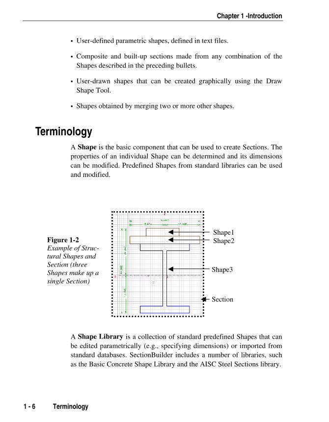
Terminology A Shape is the basic component that can be used to create Sections. Theproperties of an individual Shape can be determined and its dimensionscan be modified. Predefined Shapes from standard libraries can be usedand modified.
\
A Shape Library is a collection of standard predefined Shapes that canbe edited parametrically (e.g., specifying dimensions) or imported fromstandard databases. SectionBuilder includes a number of libraries, suchas the Basic Concrete Shape Library and the AISC Steel Sections library.
Figure 1-2Example of Struc-tural Shapes andSection (threeShapes make up asingle Section)
Shape1Shape2
Shape3
Section

SectionBuilder User's Manual
Advantages of SectionBuilder 1 - 7
A Section is a combination or collection of Shapes placed together to actas a single cross-section. Properties are computed and the design is com-pleted for a Section, NOT for a Shape.
A Section File saves newly defined or previously defined Sections. Morethan one Section can be defined and saved in a single Section File.
A Material Factor or Stiffness Factor allows the user to handle Com-posite Sections. These factors are used to specify the relative weight ofthe Shape in the overall Section. Generally, it is the ratio of the Modulusof Elasticity of a particular Shape to the base or reference Modulus ofElasticity. However, any positive, negative or zero value may be speci-fied to handle solid (filled) and hollow (holes) shapes, or to ignoreShapes in calculation.
Advantages of SectionBuilder Most analysis programs require that the geometric properties of the ele-ment cross-section be provided as an input with the structual geometry.Some software programs have the additional capability to compute thoseproperties automatically for standard Shapes. Some programs also havethe capability to read in properties from Standard Section databases, suchas the Hot-Rolled Steel Shapes. However, many construction and re-search projects demand special sections not defined in the programs oravailable in standard databases. This is especially true with odd concreteshapes used as columns in buildings and bridge piers, for composite sec-tions in bridge decks and built-up sections in steel structures. Section-Builder has been developed to meet these needs for defining and evalu-ating general shapes and sections.
Results and Output Three types of results can be obtained from the program.
Geometric Properties
Section Capacity

Chapter 1 -Introduction
1 - 8 Results and Output
Stress Distribution
The program can handle several types of Sections, including a simpleconcrete Section made from a single Shape, a simple steel Section madefrom a single steel Shape, complex steel and concrete Sections built-upby combining several basic Shapes, a composite Section made up ofShapes of different materials, and reinforced Sections where reinforcingis added to the Shapes. Even for Sections made from concrete Shapesalone, each component Shape may have different properties. It is there-fore important to understand the basis for calculations and the meaningof different results, which will be described in the following subsections.
Geometric Properties The geometric properties are computed and reported in terms of the basematerial property (global material type) defined for the Section. That is,if the material specified for the Section is concrete of a particularstrength, the properties of all Shapes in that Section will be weighted(transformed) with the appropriate factors using the concept of modularratio. The modular ratio of the Shapes in the Section is computed as:
nshape = Eshape/Esection
The individual properties of the Shape will be multiplied by this factorand added to the properties of other Shapes. This is true even if there isonly a single Shape in the Section. Therefore, it is possible to computethe property of even a single Shape Section in terms of other materials.For reference, the base material of the Section is always shown on theStatus bar of the main screen.
Section Capacity The Section capacity can be obtained in basically two ways.
Capacity interaction curves
Moment-curvature plots
The interaction curves are displayed as:

SectionBuilder User's Manual
Results and Output 1 - 9
Load and biaxial moment interaction surface showing a 3D plot be-tween the axial load P, moment Mx and moment My
Load-moment interaction curve showing the relationship of axial loadcapacity and the resultant moment capacity at a specified angle of neu-tral axis
Moment-moment interaction curve showing a plot between momentcapacity about the X-axis and moment capacity about the Y-axis at aspecified axial load level
All these curves can be obtained for the following three cases:
Capacity values including the capacity reduction factors as defined inthe appropriate design code
Capacity values without the capacity reduction factors as defined in theappropriate design code
Capacity values with the specified yield strength of reinforcements in-creased by 25%, without including the capacity reduction factors
The capacity calculations are performed on the basis of the materialproperties specified for individual component Shapes in the Section. Inother words, the capacity of each individual Shape is computed inde-pendently and the individual capacities are then summed to find the ca-pacity of the entire Section. Therefore, the base material properties se-lected and defined for the Section have no effect on the capacity calcula-tions. The capacity calculations are performed on the basis of plasticSections and Shapes and do not consider local buckling of the Sectioncomponents.
IMPORTANT NOTE Although the program can generate capacity curves for any Sectionand combination of different Shapes and materials, it is importantthat this information be used with the proper understanding andchecks of the validity and applicability of such calculations.
In general, the capacity calculations are intended for reinforced concreteSections, but can also be used for fully composite and plastic Sections.All capacity calculations are performed using general first-principle pro-

Chapter 1 -Introduction
1 - 10 Results and Output
cedures and are in accordance with the provisions of the design code se-lected using the Options menu > General Options command. The ca-pacity stress resultants are calculated at the plastic centroid of the overallcross-section.
Stress Distribution Calculations and Plots The program can generate the following stress plots for the section:
The combined normal stresses for axial load P, moment Mx and mo-ment My. This stress calculation is based on elastic properties and lin-ear strain distribution assuming fully composite and connected behav-ior of various Shapes in the Section.
The shear stress distribution caused by shear along the y-axis alone,along the x-axis alone, torsion alone, and their various combinations.
Shear and torsional stresses are computed using the general equations.The same equations are also used to calculate the shear area. All Shapesin the Section are assumed to be fully connected and fully effective in re-sisting torsion and shear force. The shear stress distribution is computedalong two orthogonal axes independently, assuming no interaction, and ifboth the components are present, the computed stresses are added forcombined effect.
Overview 2 - 1
Chapter 2
Screens, Toolbars and Menus
Overview The overall conceptual layout of the SectionBuilder is shown in Figure2-1. The interface is highly user friendly and intuitive. The workspacefeatures various menus, toolbars, graphical editing tools and displays.Figure 2-2 shows the actual layout of features on the startup screen or themain workspace. Each of these components has been described in detailin the subsequent subsections.
The components of the main workspace include the following:
Menus and Toolbars
Main Drawing Area
Properties Window
Status Bar
CSISectionBuilder

Chapter 2 -Screens, Toolbars and Menus
2 - 2 Overview
Figure 2-1: Key Components of SectionBuilder
Figure 2-2: SectionBuilder Main User Interface Layout - Screen Shot
SectionBuilder User's Manual
Main Working Area 2 - 3
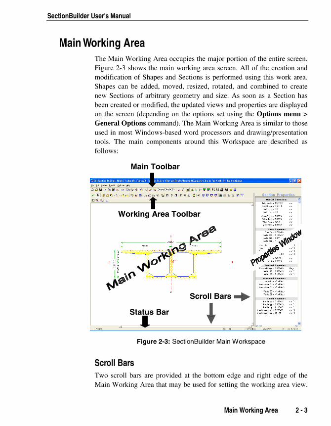
Main Working Area The Main Working Area occupies the major portion of the entire screen.Figure 2-3 shows the main working area screen. All of the creation andmodification of Shapes and Sections is performed using this work area.Shapes can be added, moved, resized, rotated, and combined to createnew Sections of arbitrary geometry and size. As soon as a Section hasbeen created or modified, the updated views and properties are displayedon the screen (depending on the options set using the Options menu >General Options command). The Main Working Area is similar to thoseused in most Windows-based word processors and drawing/presentationtools. The main components around this Workspace are described asfollows:
Working Area Toolbar
Main Toolbar
Status Bar
Scroll Bars
Working Area Toolbar
Main Toolbar
Status Bar
Scroll Bars
Figure 2-3: SectionBuilder Main Workspace
Scroll Bars Two scroll bars are provided at the bottom edge and right edge of theMain Working Area that may be used for setting the working area view.

Chapter 2 -Screens, Toolbars and Menus
2 - 4 Main Working Area
They work in conjunction with the zoom buttons. Scroll Bars becomeactive only if the full section area is not visible. This occurs when usinghigh scale zooms.
Gridlines By default, the Main Working Area is filled with a "graph paper" typegrid. These gridlines are useful for placing, aligning and resizing Shapesand Sections. The gridlines can be customized using options such asHide/Show Gridlines and Snap to Grid (see “Snap to Grid” later in thischapter for more information). Click the Plan Grid Size button to
open the Paper Grid Size form shown in Figure 2-4 to edit the horizontaland vertical grid spacing.
Figure 2-4: Editing Plan Grid Size in SecitonBuilder
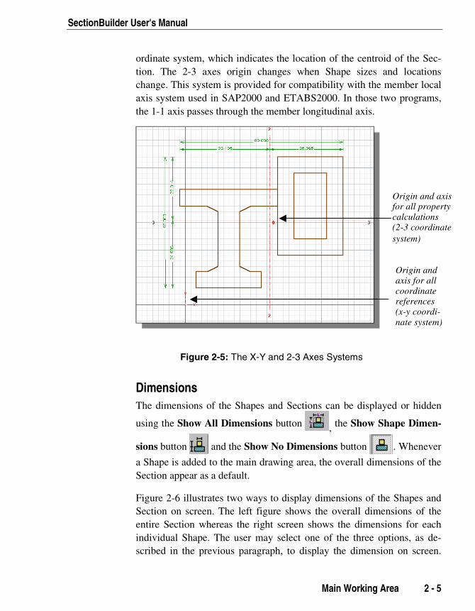
Axis Various editing operations, computed properties, Shape locations, andother items are referenced to the global X and Y axes. These axes help tolocate, move, align, and rotate the Shapes properly by providing a com-mon origin.
In Figure 2-5, the screen shows two pairs of axes. The first pair is X-Y,which is a global fixed reference on the screen. The second is the 2-3 co-
SectionBuilder User's Manual
Main Working Are
ordinate system, which indicates the location of the centroid of the Sec-tion. The 2-3 axes origin changes when Shape sizes and locationschange. This system is provided for compatibility with the member localaxis system used in SAP2000 and ETABS2000. In those two programs,the 1-1 axis passes through the member longitudinal axis.
Figure 2-5: The X-Y and 2-3 Axes Systems
Dimensions The dimensions of the Shapes and Sections can be displaye
using the Show All Dimensions button , the Show Sh
sions button and the Show No Dimensions button
a Shape is added to the main drawing area, the overall dimenSection appear as a default.
Figure 2-6 illustrates two ways to display dimensions of theSection on screen. The left figure shows the overall dimenentire Section whereas the right screen shows the dimensioindividual Shape. The user may select one of the three optscribed in the previous paragraph, to display the dimension
Origin and axisfor all propertycalculations(2-3 coordinatesystem)
Origin andaxis for allcoordinatereferences(x-y coordi-nate system)
a 2 - 5
d or hidden
ape Dimen-
. Whenever
sions of the
Shapes andsions of thens for eachions, as de- on screen.

Chapter 2 -Screens, Toolbars and Menus
2 - 6 Toolbars and Menus
For more information about these toolbar functions, see the "Toolbars"subsection.
Figure 2-6: Dimensions Displayed for the Section andDimensions Displayed for the Shape, respectively
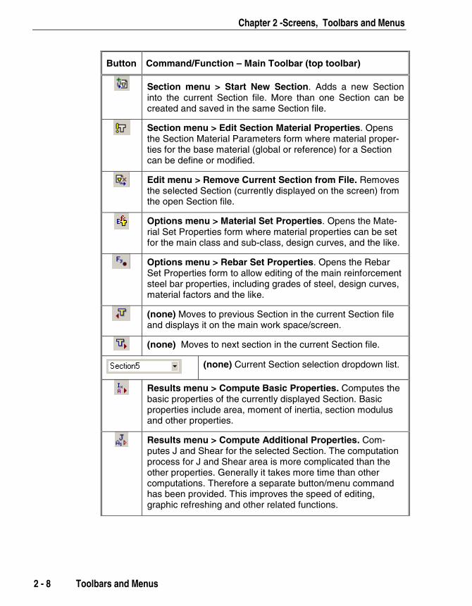
Toolbars and Menus Almost all of the menu commands have an associated toolbar button. Thebuttons have been grouped into toolbars for ease of use based on type offunction/task. The following table provides a graphic of the toolbar but-ton, the menu command, and a description of the function of the but-ton/command. The information is presented in order of the appearance ofthe buttons on the toolbar. Scan the second column of the table to locatemenu commands. When a file menu command has no button, that com-mand is provided following the other commands on the same menu.
Button Command/Function – Main Toolbar (top toolbar)
File menu > New Section File. Creates a new Section file.The previous file is closed and if it has not already beensaved, the program asks for the name of the file to save itbefore closing it.
File menu > Open Section File. Opens an existing Sectionfile. If the current file has not been saved, the user isprompted to save the file before the current section file can beclosed.

SectionBuilder User's Manual
Toolbars and Menus 2 - 7
Button Command/Function – Main Toolbar (top toolbar)
File menu > Save Section File. Saves the current Sectionfile. All the Sections defined in the current file (work session)are saved as a single Section file.
(none) File menu > Project Information. Opens the Project Infor-mation form to edit general information about the current fileand/or project.
(none) File menu > Print Current Section. Sends the current Sec-tion and its details for printing.
(none) File menu > Export to DXF: Exports the geometric data ofthe selected Section(s) to a .DXF file, which can be openedand edited in AutoCAD.
(none) File menu > Export Properties in PRO File. Exports theproperties of the active/current Section using the PROPERSection File or .PRO format. SAP2000 and ETABS can readthe .PRO file format. Use SAP2000 or ETABS import optionsto import .PRO property files saved by SectionBuilder.
(none) File menu > Exit. Exits the program. SectionBuilder willprompt you to save any unsaved Section files before exiting.
Edit menu > Undo. Undoes the previous action. UnlimitedUndo back to the last time the file was saved is available.
Edit menu > Cut. Cuts the selected Shapes from the Draw-ing Area and places them on the Clipboard. The cut Shapescan subsequently be pasted into the Main Drawing Area.
Edit menu > ‘Copy. Copies the selected Shapes in the MainDrawing Area onto the Clipboard. The copied Shapes can besubsequently pasted back into the Main Drawing Area.Shapes can be copied from Section to Section.
Edit menu > Paste. Pastes the Cut or Copied Shapes intothe Main Drawing Area. Shapes from one Section can be cut,copied and pasted to other Sections in the same file.
Edit menu > Delete Selection. Deletes the currently se-lected Shape(s) from the Main Drawing Area. Undo will re-store the deleted Shape(s) as long as the file has not beensaved since the Shape(s) was deleted.
IMPORTANTNOTEStarting a newSection usingthe Sectionmenu > StartNew Sectioncommand isnot the sameas starting anew Sectionfile using theFile menu >New SectionFile com-mand.
Chapter 2 -Screens, Toolbars and Menus
2 - 8 Toolbars and Menus
Button Command/Function – Main Toolbar (top toolbar)
Section menu > Start New Section. Adds a new Sectioninto the current Section file. More than one Section can becreated and saved in the same Section file.
Section menu > Edit Section Material Properties. Opensthe Section Material Parameters form where material proper-ties for the base material (global or reference) for a Sectioncan be define or modified.
Edit menu > Remove Current Section from File. Removesthe selected Section (currently displayed on the screen) fromthe open Section file.
Options menu > Material Set Properties. Opens the Mate-rial Set Properties form where material properties can be setfor the main class and sub-class, design curves, and the like.
Options menu > Rebar Set Properties. Opens the RebarSet Properties form to allow editing of the main reinforcementsteel bar properties, including grades of steel, design curves,material factors and the like.
(none) Moves to previous Section in the current Section fileand displays it on the main work space/screen.
(none) Moves to next section in the current Section file.
(none) Current Section selection dropdown list.
Results menu > Compute Basic Properties. Computes thebasic properties of the currently displayed Section. Basicproperties include area, moment of inertia, section modulusand other properties.
Results menu > Compute Additional Properties. Com-putes J and Shear for the selected Section. The computationprocess for J and Shear area is more complicated than theother properties. Generally it takes more time than othercomputations. Therefore a separate button/menu commandhas been provided. This improves the speed of editing,graphic refreshing and other related functions.
SectionBuilder User's Manual
Toolbars and Menus 2 - 9
Button Command/Function – Main Toolbar (top toolbar)
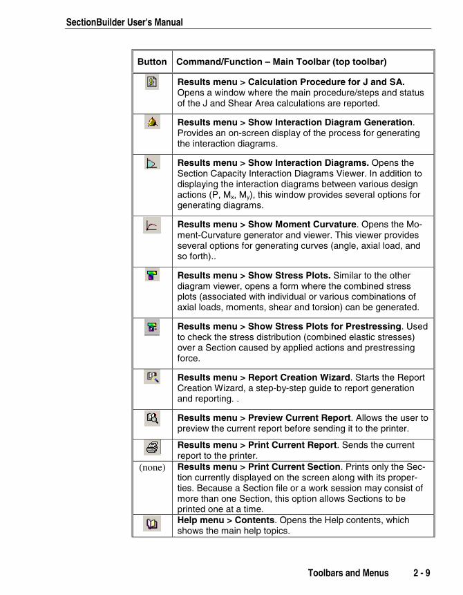
Results menu > Calculation Procedure for J and SA.Opens a window where the main procedure/steps and statusof the J and Shear Area calculations are reported.
Results menu > Show Interaction Diagram Generation.Provides an on-screen display of the process for generatingthe interaction diagrams.
Results menu > Show Interaction Diagrams. Opens theSection Capacity Interaction Diagrams Viewer. In addition todisplaying the interaction diagrams between various designactions (P, Mx, My), this window provides several options forgenerating diagrams.
Results menu > Show Moment Curvature. Opens the Mo-ment-Curvature generator and viewer. This viewer providesseveral options for generating curves (angle, axial load, andso forth)..
Results menu > Show Stress Plots. Similar to the otherdiagram viewer, opens a form where the combined stressplots (associated with individual or various combinations ofaxial loads, moments, shear and torsion) can be generated.
Results menu > Show Stress Plots for Prestressing. Usedto check the stress distribution (combined elastic stresses)over a Section caused by applied actions and prestressingforce.
Results menu > Report Creation Wizard. Starts the ReportCreation Wizard, a step-by-step guide to report generationand reporting. .
Results menu > Preview Current Report. Allows the user topreview the current report before sending it to the printer.
Results menu > Print Current Report. Sends the currentreport to the printer.
(none) Results menu > Print Current Section. Prints only the Sec-tion currently displayed on the screen along with its proper-ties. Because a Section file or a work session may consist ofmore than one Section, this option allows Sections to beprinted one at a time.Help menu > Contents. Opens the Help contents, whichshows the main help topics.

Chapter 2 -Screens, Toolbars and Menus
2 - 10 Toolbars and Menus
Button Command/Function – Main Toolbar (top toolbar)
Help menu > Send Email to CSI. For sending Email to CSI.Internet connection is needed for this option to work.Help menu > Go to CSI Web Site. Connects to the CSIwebsite. Internet connection is needed for this option to work
Button Command/Function – Working Area Toolbar
(none) Refreshes all views and calculates the section proper-ties.
(none) Activates the Shape(s) selection mode.
Section menu > Add Shape from Library. Opens View andSelect Library Shapes form to add Shape to Section.
Section menu > Draw Shape. Changes the editing mode toShape drawing mode. Draw the nodal points of any polyno-mial Shape by clicking on the left mouse button (double clickto end)..
Section menu > Add Basic Concrete Shapes. Opens se-lection list to add Basic Concrete Shapes to the current Sec-tion. Allows user to quickly select and add commonly usedbasic concrete shapes (e.g., rectangular, tee, circular), andalso provides access to other concrete basic shape libraries.
Section menu > Add Basic Steel Shapes. Opens selectionlist to add Basic Steel Shapes to the current Section. Allowsuser to quickly select and add commonly used basic steelshapes (e.g., I, C, T, L) and also provides access to othersteel basic shape libraries.
Section menu > Merge Using Mesh. Merges two currentlyselected Shapes of the same material type using mesh-Merges two selected Shapes that overlap or share a commonboundary using meshing. The area of overlap is removedwhen the Shapes are merged.
Section menu > Merge Using Outline. Merges two currentlyselected Shapes of the same material type using outline-Merges two selected Shapes that overlap or share a commonboundary using outline The lines within the Shape boundaryare neglected when the Shapes are merged.

SectionBuilder User's Manual
Toolbars and Menus 2 - 11
Button Command/Function – Working Area Toolbar
Section menu > Edit Current Shape. Opens the ShapeEditor screen/form for the currently selected Shape. TheShape Editor is used to modify assign the dimensions (e.g.,width, height, thickness), and material properties, PropertyMultiplier, stress-strain curve, rebar, and the like of to atheselected Shape.
Section menu > Edit Shape Points. Shows the node pointsof the current Shape for relocating or moving with using themouse. If the current sShape is a standard database Shape,the user will be prompted to convert it to user-drawn Shape.
Section menu > Edit Shape Layout. Opens the Shape Lay-out Editor form to locate place Shapes by specifying coordi-nates and angleswhere the parameters defining the position(e.g., point coordinates, angle) of a Shape in the Main Work-ing Area can be edited numerically.
Section menu > Rotate and Flip Shapes > Rotate Right.Rotates the selected Shape by 90 degrees to the right.
Section menu > Rotate and Flip Shapes > Rotate Left.Rotates the selected Shape by 90 degrees to the left.
Section menu > Rotate and Flip Shapes > Rotate Section.Rotates the entire Section by a specified angle. The optionsavailable for rotation are as follows:
Rotate to Align with Principal Axis: Rotates the activeSection to align it with its Principal Axis. If the Section’s cur-rent orientation is along the Principal Axis, no rotation takesplace.
Rotate by Angle about Centroid of the Section: Rotatesthe Section about its centroid at a user-defined angle speci-fied in degrees. Positive angles define rotation in the coun-ter clockwise direction while negative angles result in clock-wise rotation.
Rotate by Angle about a Specified Point: Rotates theSection by an angle specified in degrees about any user-specified point defined in terms of x and y coordinate. Posi-tive angles define rotation in the counterclockwise directionwhile negative angles result in clockwise rotation.
Section menu > Rotate and Flip Shapes > Flip Horizontal.Flips the selected Shape on the vertical axis (mirror).
Chapter 2 -Screens, Toolbars and Menus
2 - 12 Toolbars and Menus
Button Command/Function – Working Area Toolbar
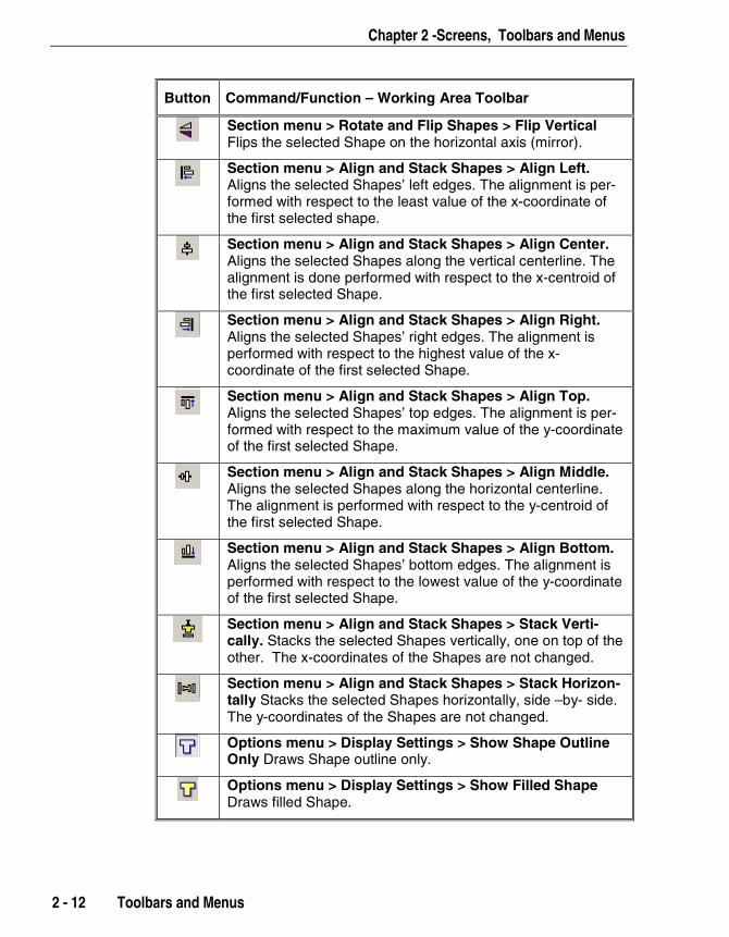
Section menu > Rotate and Flip Shapes > Flip VerticalFlips the selected Shape on the horizontal axis (mirror).
Section menu > Align and Stack Shapes > Align Left.Aligns the selected Shapes’ left edges. The alignment is per-formed with respect to the least value of the x-coordinate ofthe first selected shape.
Section menu > Align and Stack Shapes > Align Center.Aligns the selected Shapes along the vertical centerline. Thealignment is done performed with respect to the x-centroid ofthe first selected Shape.
Section menu > Align and Stack Shapes > Align Right.Aligns the selected Shapes’ right edges. The alignment isperformed with respect to the highest value of the x-coordinate of the first selected Shape.
Section menu > Align and Stack Shapes > Align Top.Aligns the selected Shapes’ top edges. The alignment is per-formed with respect to the maximum value of the y-coordinateof the first selected Shape.
Section menu > Align and Stack Shapes > Align Middle.Aligns the selected Shapes along the horizontal centerline.The alignment is performed with respect to the y-centroid ofthe first selected Shape.
Section menu > Align and Stack Shapes > Align Bottom.Aligns the selected Shapes’ bottom edges. The alignment isperformed with respect to the lowest value of the y-coordinateof the first selected Shape.
Section menu > Align and Stack Shapes > Stack Verti-cally. Stacks the selected Shapes vertically, one on top of theother. The x-coordinates of the Shapes are not changed.
Section menu > Align and Stack Shapes > Stack Horizon-tally Stacks the selected Shapes horizontally, side –by- side.The y-coordinates of the Shapes are not changed.
Options menu > Display Settings > Show Shape OutlineOnly Draws Shape outline only.
Options menu > Display Settings > Show Filled ShapeDraws filled Shape.

SectionBuilder User's Manual
Toolbars and Menus 2 - 13
Button Command/Function – Working Area Toolbar
Options menu > Display Settings > Show Meshed ShapeDraws filled Shape showing mesh used for computing J.
Options menu > Display Settings > Show Mesh Showsmesh used for computing J.
Options menu > Display Settings > Show Overall Dimen-sions Shows overall dimensions of the entire Section.
Options menu > Display Settings > Show Shape Dimen-sions Shows dimensions for each Shape in the Section.
Options menu > Display Settings > Show No DimensionsShows no dimensions on the Section.
(none) Shows/Hides the gridlines. This can be used to hidegridlines for a clearer view of the Shapes and the Sections inthe Main Drawing Area.
(none) Opens the Paper Grid Size form. The spacing of themajor and minor grids can be edited here.
(none) Toggles the Snap to Grid option. If Snap to Grid isactivated, the mouse makes only discrete movements, whichare defined by simple multiples of the grid. This affects mov-ing and resizing Shapes. For more precise control, you maywish to modify the grid sizes: switch off the Snap to Grid op-tion or use the Shape Layout Editor. The left, right, up anddown arrows on the keyboard can also be used to moveShapes.
(none) Resets the current view in such a way that the entireSection is visible, showing all Shapes on the Main DrawingArea.
(none) Increase the Zoom. In many situations it may be nec-essary to display the Shapes and Sections on a larger scale.Sometimes this may also be required to view a small portionof the current Section on a large scale. The Zoom In buttonmay be used in association with the horizontal and verticalscroll bar to set the appropriate view.
(none) Decrease the zoom to see more of the Section in theview. It is the opposite function to Zoom In.
Section menu > Add Section to Report. Adds the currentlydisplayed Section to the current report, which can be custom-ized, previewed, and printed.
Chapter 2 -Screens, Toolbars and Menus
2 - 14 Properties Window
Button Command/Function – Working Area Toolbar
(none) Options menu > General Options. Affects all the sectionsglobally in the current file. Those options include the workingunits, number format and the design code. The standardsspecified in the codes are used for calculating various pa-rameters needed to generate the Capacity Interaction Surfaceand Moment Curvature relationships. Those parameters in-clude capacity reduction factors, cutoff values for axial com-pression, maximum allowable strain in concrete and materialreduction factors.
(none) Options menu > View Options. Specifies different colors forthe display of different items. The border and fill color of thevarious items can be changed. More options are available forsetting the drawing area, switching on or off the auto refresh,calculation of properties options, and the like.
(none) Options menu > Display Settings. Controls show/hide ofShape/Section dimensions, display of filled or outlined areas,and setting for the workspace gridlines
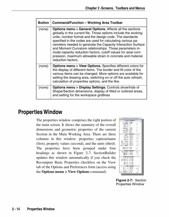
Properties Window The properties window comprises the right portion ofthe main screen. It shows the summary of the overalldimensions and geometric properties of the currentSection in the Main Working Area. There are threecolumns in this window: properties caption/name(first), property values (second), and the units (third).The properties have been grouped under fourheadings as shown in Figure 2-7. SectionBuilderupdates this window automatically if you check theRecompute Basic Properties checkbox on the Viewtab of the Options and Preferences form (access usingthe Options menu > View Options command).
Figure 2-7: SectionProperties Window
SectionBuilder User's Manual
Undo Function 2 - 15
Undo Function The program tracks every user operation. The Undo button and theEdit menu > Undo command can retrace the steps performed back to thelast time the file was saved.
Snap To Grid By default, the movement and sizing of the Shapes is snapped to thenearest grid. The snap location is automatically determined by themovement direction of the Shape. Turn this feature off and on using the
Snap to Grid button . If Snap to Grid is active when the Shape is
moved or resized using the mouse or the arrow keys, the movements willbe multiples of the grid. For more precise control, modify the grid sizesor use the Shape Layout Editor described in Chapter 3.
Stress-Strain Curves for Materials A variety of stress-strain curves are available for concrete, steel and rein-forcing bars in the program. These material curves may be assigned tothe selected Shape using the Shape Editor and choosing the relevantcurve from the Stress-Strain Curve drop-down list. If a Section containsmore than one Shape, different stress-strain curves may be assigned toeach Shape. The curves available for each type of material are listed be-low.
Concrete ACI Whitney Rectangle
BS 8110 Rectangle
CAS Rectangle
EuroCode2 Rectangle
AASHTO Rectangle
NZ Rectangle
UBC97 Rectangle
Chapter 2 -Screens, Toolbars and Menus
2 - 16 Stress-Strain Curves for Materials
IS 456 Rectangle
Simple Parabola
PCA Parabola
BS 8110 Parabola
Mander Circular Confined
Mander Rectangular Confined
Mander Un-confined
Service Triangle
User-Defined Curve (3 Curves Available)
Steel Elasto-Plastic
Elastic Only
Park, Strain Hardening
Simple Strain Hardening
User-Defined Curve (3 Curves Available)
Reinforcing Bars Elasto-Plastic
Elastic Only
Park, Strain Hardening
Simple Strain Hardening
User-Defined Curve (3 Curves Available)

3 - 1
Chapter 3
Creating Sections
IntroductionThis chapter describes how to use SectionBuilder to quickly create newstructural Sections and compute their properties. It is been assumed thatthe user is familiar with the basic concepts of structural mechanics (espe-cially the structural interpretation of the section properties, section ca-pacities, and the like) and structural analysis. The main topics include thegeneral process for creating a Section, and more detailed descriptions ofdefining material properties, adding sections from library files, drawingsections, assigning materials properties to individual Shapes, computingSection properties, and previewing and printing reports.
Before working with a Section, it is essential that you understand the dif-ference between a Shape and a Section as used in SectionBuilder. A Sec-tion is made up of a one or more Shapes of the same or different mate-rial. See Chapter 1 for further clarification.
CSISectionBuilder

SectionBuilder Users Manual
General Process for Creating a Section While the sequence of steps you take may differ, the basic process forcreating and editing Sections in a Section File, computing Section prop-erties, and generating a report is as follows:
1. When you start the program, SectionBuilder opens a default Sectionnamed Section1. The Main Working Area will have a graph-paper-type grid with the X-Y and 2-3 coordinate systems displayed. If de-sired, use the File menu > Project Information command to recordproject information for the Section file (e.g., project name, projectnumber, organization, and so forth). This information will appear onprinted reports. Then use the File menu > Save Section File or the
Save Section File button to save the section file.
2. Set the units to the desired system using the Options menu > Gen-
Note:A section filecan be savedat any timeduringcreation.Saving earlyand often willhelp preventdata loss.
3 - 2 General Process for Creating a Section
eral Options command. Choose inches, feet, millimeters, centime-ters or meters.
3. Use the Options menu > Material Set Properties command or the
Material Set Properties button to access the Material Set Prop-erties form where you can review and change the Basic MaterialProperty and Sub Type Material. The basic material is the global ref-erence material and the material in terms of which all the sectionproperties will be computed. The Sub Type Material allows the useof different grades of concrete and steel.
4. Change the Section name and assign material properties to the Sec-tion. Click the Section menu > Edit Section Properties commandor the Section Materials Properties button to access the Sec-tion Material Parameters form. Type a name for the Section in theSection Caption edit box.
5. Use one of the following tools to add a Shape to the current Section:
Add new shape to current Section button opens theView and Select Library Shapes window where you canselect a Shape from a library and double click on it to addit.
Note:Shapes in thesame Sectioncan have differ-ent materialtypes. However,the materialtypes will beconverted by theprogram to bein terms of thebase materialtype forcalculation.

Chapter 3 - Creating Sections
General Process for Creating a Section 3 - 3
Draw Closed Shape button enables the draw mode; clickthe left mouse button in the Main Working Area at thecorner points of the Shape you want to draw.
Add Basic Concrete Shape button displays a drop-downlist of available concrete Shapes; highlight a Shape to addit.
Add Basic Steel Shape button displays a drop-down listof available steel Shapes; highlight a Shape to add it.
6. If appropriate, use the Add Fillets tools to add fillets at Shape points.
7. Double click on a Shape to access the Shape Editor. Use the ShapeEditor to refine the dimensions and make property assignments, in-cluding a stiffness factor (Property Multiplier) and a stress-strain re-lationship for the Shape. If desired, add rebar to the Shape using theShape Editor toolbar buttons. Save the section file.
8. Click on the Shape(s) and use the arrow keys, mouse and toolbarbuttons to align, rotate, flip, or merge Shapes and add "holes" to cre-ate the desired Section. If appropriate, use the Shape Layout Editorto precisely position shape nodes. Save the section file.
9. To compute the Section properties based on the dimensions and ma-terial properties defined for the Section, click the Compute Basic
Properties button ; when that computation is complete, click the
Compute Torsional Constant and Shear Area button . Save thesection file.
10. Add another Section to the Section file by clicking the Add NewSection button . Change the Section Caption using the SectionMaterial Parameters form (click the Section Materials Propertiesbutton ); if necessary, click the Edit button to access the MaterialSet Properties form to adjust the property definition. Repeat Steps 4through 9. Save the section file.
11. Click the Report Generation Wizard button and select theitems to be included in a printed report for the Section. Click the
Preview Current Report button to review the report before
using the Print Current Report button . Save the section file.
SectionBuilder Users Manual
The other sections in this chapter provide more details about this process,along with explanations about the program and the parameters used in it.
General Process for Creating a Caltrans SectionSeveral parametrically defined Sections conforming to Caltrans require-ments are available. While the sequence of steps you take may differ, thebasic process for creating Caltrans Sections in a Section File, computingSection properties, and generating a report is as follows:
1. When you start the program, SectionBuilder opens a default Sectionnamed Section1. The Main Working Area will have a graph-paper-type grid with the X-Y and 2-3 coordinate systems displayed. If de-sired, use the File menu > Project Information command to recordproject information for the Section file (e.g., project name, projectnumber, organization, and so forth). This information will appear on
Note:Caltrans isthe managerof inter-regionaltransporta-tion servicesfor the stateof California,USA.
printed reports. Then use the File menu > Save Section File or the
Save Section File button to save the section file.
2. Set the units to the desired system using the Options menu > Gen-eral Options command. Choose inches, feet, millimeters, centime-ters or meters.
3. Change the Section name by clicking the Section menu > Edit Sec-tion Properties command or the Section Materials Propertiesbutton to access the Section Material Parameters form. Type aname for the Section in the Section Caption edit box.
4. Click the Section menu > Start New CALTRAN Section commandto bring up the CALTRANS Sections form, shown in Figure 3-1.
Note:A section filecan be savedat any timeduringcreation.Saving earlyand often willhelp preventdata loss.
3 - 4 General Process for Creating a Caltrans Section
5. Select the cross-section type by clicking on the appropriate button inthe Basic Section Type area of the form. The display window willshow the Shape and dimensions of the selected Section type.
6. Select a Cross-section Size from the Standard drop-down list orspecify the Height, H by typing in the edit box. When you select theStandard cross-section type, the Section in the display window willbe automatically updated with the default dimensions. If you specifythe Height, click the Refresh button to display the Section.

Chapter 3 - Creating Sections
General Process for Creating a Caltrans Section 3 - 5
Figure 3-1 Caltrans Sections Form
7. As necessary, specify Outer Layer Rebar and Inner Layer Rebar, toarrange the rebar in the cross-section in two layers. Select the barsize from the drop-down list and specify the number of bars. Differ-ent bar sizes and numbers can be specified for both layers of rein-forcement.
8. Select the bar size for the spiral and its pitch. Transverse reinforce-ment is always provided in spiral form for CALTRANS Sections.This can be changed; see Step 11.
SectionBuilder Users Manual
3 - 6 General Process for Creating a Caltrans Section
9. Specify other material properties as necessary, such as concretestrength, steel yield strength for main and spiral reinforcements, andthe clear cover to the longitudinal bars. The extent of the confinedportion is governed by the cover provided.
By default, the inner circular confined concrete region of all definedSections is assigned a Mander Circular Confined stress-strain curves,while the outer portion is assigned a Mander Unconfined stress-strainrelationship.
10. Assign a steel model to the reinforcing bars. By default, the Park'sStrain Hardening model is assigned. To change the assignment, clickthe Rebar S/S Curve button to activate the Assign Stress-StrainCurve form. Select the required steel model from the drop-down list.Use the Edit button to view/edit the parameters of the selectedcurves.
The confinement extent and parameters are automatically computedby the program using the reinforcing bar size, its spacing and thecover specified.
11. Click the OK button. SectionBuilder will display the Section in theMain Working Area. Save the section file.
Similar to all other parametrically defined Sections, CALTRANSSections can be edited. For example, click the Section menu > EditSection Properties command or the Section Materials Propertiesbutton to access the Section Material Parameters form and clickthe Ties checkbox to change the transverse reinforcement from spiralto ties. Other parameters can be modified by clicking the Edit buttonon the Section Material Parameters form to access the Material SetProperties form. To modify a Shape that makes up the Section, dou-ble click on it to access the Shape Editor.
12. To compute the Section properties based on the dimensions and ma-terial properties defined for the Section, click the Compute Basic
Properties button ; when that computation is complete, click the
Compute Torsional Constant and Shear Area button . Save thesection file.
13. Add another Section to the Section file by clicking the Add NewSection button . Change the Section Caption using the Section

Chapter 3 - Creating Sections
Material Parameters form (click the Section Materials Propertiesbutton ); if necessary, click the Edit button to access the MaterialSet Properties form to adjust the property definition. Repeat Steps 4through 12 as necessary.
14. Click the Report Generation Wizard button to select the itemsto be included in a printed report for the Section. Click the Preview
Current Report button to review the report before using the
Print Current Report button . Save the section file.
Sections and Section FilesSection files store the individual Sections. More than one Section can bestored within a single Section file. The topics covered in the paragraphsthat follow describe adding, naming, accessing, and deleting Sectionswithin a Section file and creating, opening and saving Section files.
Add a Section to a Section File and Change Its NameUse the Section menu > Add New Section command or click the Add
New Section button to add a blank Section to the open section file.SectionBuilder will suggest sequential section names or Section Captions(i.e., Section1, Section2, Section3 and so forth).
Change the Section Caption on the Section Material Parameters form,shown in Figure 3-2, which is accessed using the Section menu > EditSection Material Properties command or the Section Material Proper-ties button .
Note: The statusbar at thebottom of thewindowdisplays thetotal numberof Sections ina Section fileas well as thebase materialtype (i.e.,Concrete orHot-RolledSteel).
Sections and Section Files 3 - 7
Move from Section to Section within a Section FileThe Section Captions for the Sections within the same section file dis-play in the Section List on the toolbar. Use the Previous/Next buttons
(left and right arrows) to navigate between the Sec-tions in the open Section file.

SectionBuilder Users Manual
3 - 8 Sections and Section Files
Figure 3-2 Change Section Captions using theSection Material Parameters Form
Delete a Section from a Section FileUse the Section menu > Remove Current Section From File command
or click on the Remove Current Section form File button to re-move/delete the currently displayed Section from the open Section file.Note that a deleted Section can be restored using the Undo command aslong as the section file has not been saved since the Section was deleted.
Create and Save a Section FileUse the File menu > New Section File command or click the New Sec-
tion File button to create a section file. Similar to other Windows-
based programs, SectionBuilder will prompt you to save the unsavedsection file, if any, before creating a new one. It is recommended thatyou save any unsaved files before starting a new Section file.
Use the File menu > Save Section File or File menu > Save Section
File As command or the Save Section File button to save the sec-
tion file at any stage of creation. SectionBuilder will prompt you for afilename and path.

Chapter 3 - Creating Sections
Define Material Properties 3 - 9
Open a Section FileUse the File menu > Open Section File command or the Open Section
File button to open a previously saved section file. SectionBuilder
will prompt you to save an unsaved section file, if any, before openinganother one. SectionBuilder will prompt you for the filename and path.
Export Sections to a .DXF FileClick the File menu > Export to .DXF File command to access the Ex-port Sections to DXF form and export the geometric data of the selectedSection(s) to a DXF file. AutoCAD can open and DXF files.
In the Select Sections to Include area of the Export Sections to DXFform, check the check boxes of the Sections you wish to include in theexport. SectionBuilder provides default selections for the other prefer-ences on this form, which are generally self-explanatory. Use these pref-erences or select your own from the drop-down lists, or type in the de-sired preferences to the edit boxes. When you click the Generate Filebutton, SectionBuilder will generate the file and store it under the filename and path specified in the Output DFX Filename edit box.
Export the Section File to a .PRO FileUse the File menu > Export Properties to PRO File menu to write thesection properties to a .PRO file that can be read by ETABS andSAP2000.
Delete a Section FileSectionBuilder cannot be used to delete a Section file. Use a file man-agement software, such as Windows Explorer, to delete Section files.
Define Material PropertiesIn SectionBuilder each Shape or Section must have a material property,which is defined from various input parameters. SectionBuilder provides
SectionBuilder Users Manual
3 - 10 Define Material Properties
default material property definitions and also provides tools for changingthose defaults. Define material properties as follows:
1. Click the Options menu > Material Set Properties command or the
Material Set Properties button to display the Section Material
Parameters form, shown in Figure 3-3.
2. On the Material Set Properties form, choose the desired parametersfor the following properties.
Basic Material. Choose Concrete or Hot-Rolled Steel from thedrop-down list to set the basic material type for the open Section.The base material is the global reference material and the materialin terms of which all the section properties will be computed. Dif-ferent Shapes in the same Section can have different material typesbut they will be converted by the program to be in terms of thebase material type for calculations.
Sub Material Type. Use the default or choose a sub-type fromthe drop-down list for the Basic Material. The sub-types define dif-ferent grades of concrete and steel. For example fc’ = 2.5 ksi to 8ksi. Similarly, if Hot-Rolled Steel is the main material type, chooseASTM-36, ASTM-50 or User Defined.
After the main and sub-type have been selected, the program dis-plays default properties values associated with the material type andsubtype for the following items. Use the defaults or overwrite themby typing in the edit boxes.
Concrete fc’ is the ultimate compressive strength of the concrete asdefined in the ACI-318 Code.
Yield Strength fy is the value of the yield strength of steel to beused in design as the main reinforcement.
Yield Strength Fys is the value of the yield strength of steel to beused as the secondary or shear/torsion reinforcement.
Ultimate Strength Fu of the steel when this is the selected mate-rial.
Note:MaterialProperties areassigned to aSection bydefault, but youcan change thepropertiesusing theSection menu >Edit SectionMaterialPropertiescommand.
Chapter 3 - Creating Sections
Define Material Properties 3 - 11
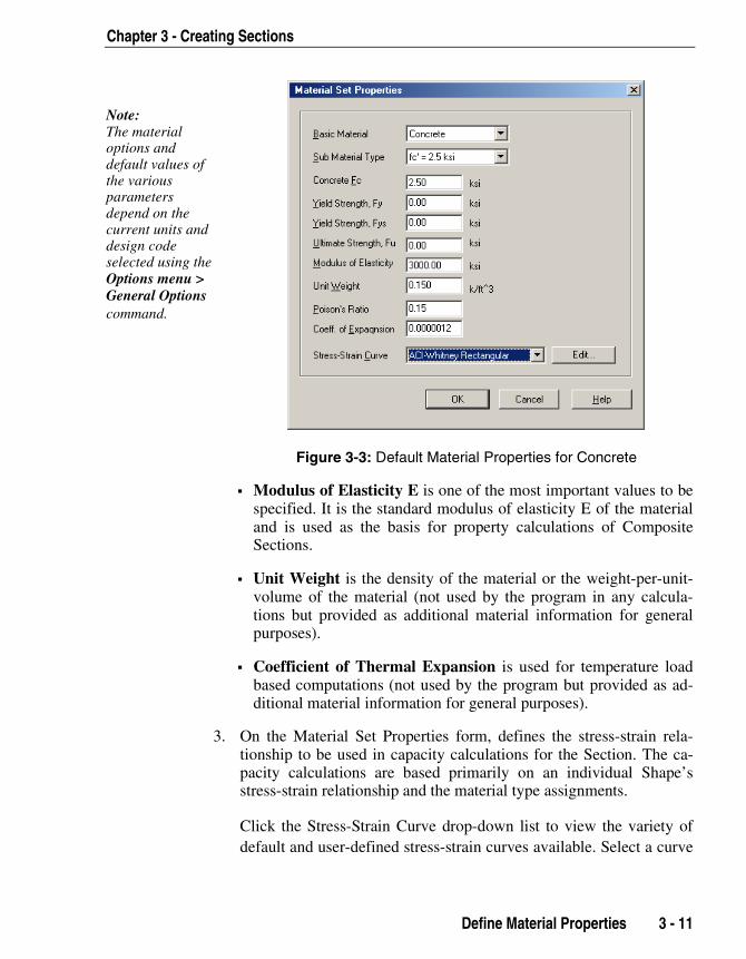
Figure 3-3: Default Material Properties for Concrete
Modulus of Elasticity E is one of the most important values to bespecified. It is the standard modulus of elasticity E of the materialand is used as the basis for property calculations of CompositeSections.
Unit Weight is the density of the material or the weight-per-unit-volume of the material (not used by the program in any calcula-tions but provided as additional material information for generalpurposes).
Coefficient of Thermal Expansion is used for temperature loadbased computations (not used by the program but provided as ad-ditional material information for general purposes).
3. On the Material Set Properties form, defines the stress-strain rela-tionship to be used in capacity calculations for the Section. The ca-pacity calculations are based primarily on an individual Shape’sstress-strain relationship and the material type assignments.
Click the Stress-Strain Curve drop-down list to view the variety ofdefault and user-defined stress-strain curves available. Select a curve
Note:The materialoptions anddefault values ofthe variousparametersdepend on thecurrent units anddesign codeselected using theOptions menu >General Optionscommand.
SectionBuilder Users Manual
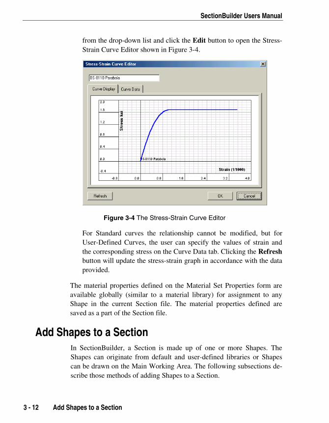
3 - 12 Add Shapes to a Section
from the drop-down list and click the Edit button to open the Stress-Strain Curve Editor shown in Figure 3-4.
Figure 3-4 The Stress-Strain Curve Editor
For Standard curves the relationship cannot be modified, but forUser-Defined Curves, the user can specify the values of strain andthe corresponding stress on the Curve Data tab. Clicking the Refreshbutton will update the stress-strain graph in accordance with the dataprovided.
The material properties defined on the Material Set Properties form areavailable globally (similar to a material library) for assignment to anyShape in the current Section file. The material properties defined aresaved as a part of the Section file.
Add Shapes to a SectionIn SectionBuilder, a Section is made up of one or more Shapes. TheShapes can originate from default and user-defined libraries or Shapescan be drawn on the Main Working Area. The following subsections de-scribe those methods of adding Shapes to a Section.
Chapter 3 - Creating Sections
Add Shapes from a LibraryShape Libraries consist of a collection of predefined Shapes that can beused to create new Shapes and Sections. The entire Shape collection isgrouped into several categories, as follows:
Basic Concrete
Basic Steel
Box Girder
Bridge Pier
Shear Wall
Fillets and Chamfers
Standard Steel Shapes that comply with the following codes:
American Institute of Steel Construction (AISC) (inch and metricunits are in separate libraries)
Canadian Institute of Steel Construction (CISC)
British Standard
User-Defined Shape Libraries
To add a Shape from one of these libraries to an open Section:
1. Select the Section menu > Add Shape From Library command orclick the Add New Shape to Current Section button . Alterna-
tively, click the Add Basic Concrete Shape button or the Add
Basic Steel Shape button and select Add Shape From Library
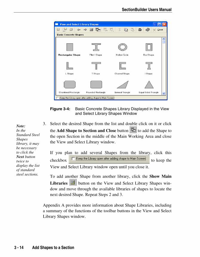
at the bottom of the drop-down list of shapes. This will open theView and Select Library Shape window. Figure 3-4 is a screen shotof the Basic Concrete Shape Library displayed in the View and Se-lect Library Shape window.
2. Select an appropriate library and click the Next button , or dou-
ble click on the selected (highlighted) library icon. A window show-ing all the Shapes in that library will appear on the screen (see Figure3-4 for an example).
Note:Appendix Aprovidesfurther infor-mation aboutShape Librar-ies, includingthe process forcreating auser-definedShape library,which canmake addingfrequently usedShapes to aSection evenquicker andeasier.
Add Shapes to a Section 3 - 13
SectionBuilder Users Manual
Figure 3-4: Basic Concrete Shapes Library Displayed in the Viewand Select Library Shapes Window
3. Select the desired Shape from the list and double click on it or click
the Add Shape to Section and Close button to add the Shape tothe open Section in the middle of the Main Working Area and closethe View and Select Library window.
If you plan to add several Shapes from the library, click this
checkbox to keep the
View and Select Library window open until you close it.
To add another Shape from another library, click the Show Main
Note:In theStandard SteelShapeslibrary, it maybe necessaryto click theNext buttontwice todisplay the listof standardsteel sections.
3 - 14 Add Shapes to a Section
Libraries button on the View and Select Library Shapes win-dow and move through the available libraries of shapes to locate thenext desired Shape. Repeat Steps 2 and 3.
Appendix A provides more information about Shape Libraries, includinga summary of the functions of the toolbar buttons in the View and SelectLibrary Shapes window.
Chapter 3 - Creating Sections
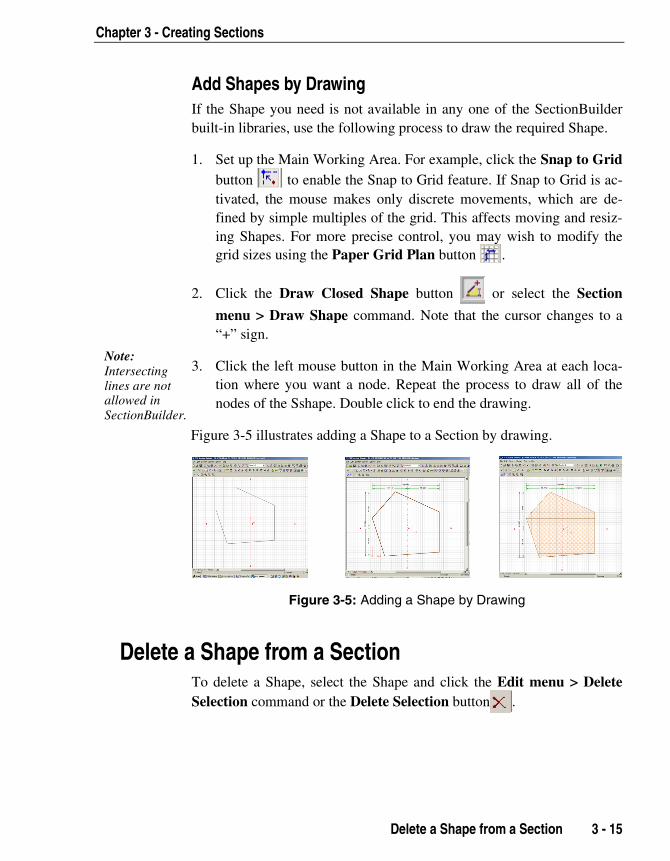
Add Shapes by DrawingIf the Shape you need is not available in any one of the SectionBuilderbuilt-in libraries, use the following process to draw the required Shape.
1. Set up the Main Working Area. For example, click the Snap to Gridbutton to enable the Snap to Grid feature. If Snap to Grid is ac-tivated, the mouse makes only discrete movements, which are de-fined by simple multiples of the grid. This affects moving and resiz-ing Shapes. For more precise control, you may wish to modify thegrid sizes using the Paper Grid Plan button .
2. Click the Draw Closed Shape button or select the Section
menu > Draw Shape command. Note that the cursor changes to a“+” sign.
3. Click the left mouse button in the Main Working Area at each loca-tion where you want a node. Repeat the process to draw all of thenodes of the Sshape. Double click to end the drawing.
Note:Intersectinglines are notallowed inSectionBuilder.
Delete a Shape from a Section 3 - 15
Figure 3-5 illustrates adding a Shape to a Section by drawing.
Figure 3-5: Adding a Shape by Drawing
Delete a Shape from a SectionTo delete a Shape, select the Shape and click the Edit menu > DeleteSelection command or the Delete Selection button .

SectionBuilder Users Manual
3 - 16 Edit or Modify a Shape
Edit or Modify a ShapeDepending on its origin, a Shape's dimensions and properties can bemodified. With respect to making these modifications, the Shapes are ofthe following four types:
Database Shapes: Code-specific steel database Shapes with dimen-sions and properties not computed using SectionBuilder.
Parametric Shapes: Basic steel and concrete Shapes defined para-metrically (i.e., by defining dimensions).
User-Drawn Shapes: Shapes created by drawing on the screen and bymodifying library Shapes added to the Section.
Merged Shapes, Including Holes: Shapes created from at least twoother Shapes.
The following table summarizes the types of Shapes and the methods tomodify them.
Table 3-1 Summary of Editable Shapes
Editing Method DatabaseShapes
ParametricShapes
User- DrawnShapes
MergedShapes Holes
Use Shape Editor tochange parametricdimensions
N/A OK OK OK OK
Use the mouse andresizing handles toresize the overall shape
N/A OK OK OK OK
Use Shape Editor tochange coordinatevalues
N/A N/A OK OK OK
Use the mouse to movenodes/change nodecoordinates
N/A OK OK OK OK
Note: OK = Allowed, N/A = Not allowed
Chapter 3 - Creating Sections
Shape EditorComplete information about a particular Shape can be viewed and editedusing the Shape Editor. The Shape Editor can be accessed using one ofthe following commands:
Click the Section menu > Edit Current Shape command.
Click the Edit Current Shape button .
Double click the left mouse button on the Shape to be edited.
The following describes some important features and functions of ShapeEditor:
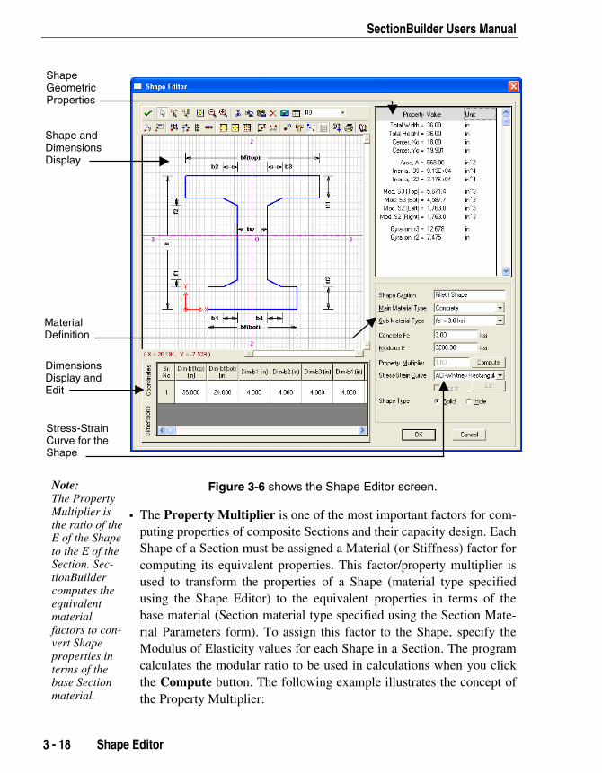
The Shape dimensions are visible on the graphic display/drawingarea. The Shape is shown in the main workspace with the orientation asdefined on the Coordinates tab. The dimensions shown in the mainworkspace match those on the Dimensions tab. Switch the displaybetween the overall dimensions of the Shape and the actual X and Ycoordinates of its corner points by clicking the Dimensions tab and theCoordinates tab. If the Shape is an editable shape (see Table 3-1), theDimensions tab is editable; the Coordinates tab is not (see "Shape Lay-out Editor" to edit coordinates points for editable Shapes). The Prop-erties area of the screen displays the properties computed for the Shapebased on the specified dimensions and material properties. When
changes are made, click the Accept Changes button on the tool-
bar to update the view and recompute the properties.
The Shape Caption, Main Material Type, Sub Material Type, Con-crete Fc and Modulus of Elasticity (E) display the parameters previ-
Note:Coordinatepoints shownon the ShapeEditor are fordisplay onlyand CANNOTbe changed.Use the ShapeLayout Editorto editcoordinates ofeditableShapes.
Note:Understand-ing thefeatures andfunctions ofthe ShapeEditor iscritical tosetting up theSection. Usethe ShapeEditor toassign Shapeproperties aswell as to addrebar to aShape.
ously defined for the Shape using the Section Material Parametersform (accessed using the Section Materials Properties button )
and the Material Set Properties form (accessed using the Material SetProperties button ). Read the next paragraph with respect to modi-
fying these parameters.
Note:Shapes canhave individualShape Cap-tions separatefrom the Sec-tion Caption.
Shape Editor 3 - 17
SectionBuilder Users Manual
3
Figure 3-6 shows the Shape Editor screen.
The Property Multiplier is one of the most important factors for com-puting properties of composite Sections and their capacity design. EachShape of a Section must be assigned a Material (or Stiffness) factor forcomputing its equivalent properties. This factor/property multiplier isused to transform the properties of a Shape (material type specifiedusing the Shape Editor) to the equivalent properties in terms of thebase material (Section material type specified using the Section Mate-rial Parameters form). To assign this factor to the Shape, specify theModulus of Elasticity values for each Shape in a Section. The programcalculates the modular ratio to be used in calculations when you clickthe Compute button. The following example illustrates the concept ofthe Property Multiplier:
Shape andDimensionsDisplay
ShapeGeometricProperties
MaterialDefinition
DimensionsDisplay andEdit
Stress-StrainCurve for theShape
Note:The PropertyMultiplier isthe ratio of theE of the Shapeto the E of theSection. Sec-tionBuildercomputes theequivalentmaterialfactors to con-vert Shapeproperties interms of thebase Sectionmaterial.
- 18 Shape Editor

Chapter 3 - Creating Sections
E for Section = 4,000 ksi (specified using the Section MaterialParameters form)
E for Shape = 3,000 ksi (specified using the Shape Editor)
Thus, the Property Multiplier for the Shape = 3,000/4,000 = 0.75
Use the Stress-Strain Curve drop-down list to assign a stress-strainrelationship to the current Shape. (The available curves were defined inthe Material Set Properties form.) Assigning a stress-strain curve toeach Shape in the Section is important with respect to computing Sec-tion capacities, as explained in Chapter 4.
Use the Shape Type check boxes to specify that the current Shape be asolid or hollow part of the Section. Use this option in conjunction withthe Stacking commands to create a Section that has a hole. Note thatthe program does not check the validity of the hole, location or size.
Shape Editor Toolbar ButtonsThe Shape Editor toolbar consists of the following buttons.
Button Function
Note:The ShapeEditordoes nothave anUndobutton.
Shape Editor 3 - 19
Accepts the latest changes and updates the graphics andproperties window. The Shape Editor window remains ac-tive.
Sets the cursor to select mode so you can select items in thedisplay area.
Click to add rebar, then place the cursor in the display areaand click the left mouse button to add rebar of the diametershown on the drop down list. This mode will remain activatedas long as this button remains selected. Click on it again toreturn to normal mode (selection mode) or click the selectionbutton.

SectionBuilder Users Manual
3 - 20 Shape Editor
Button Function
Click this button and then move the cursor to "hover" overrebar in the display area. A message box will then appearand display the rebar property.
Select rebar in the display area and click this button to re-move it and place it on the Clipboard. The cut Shape canthen be pasted onto the Shape Editor display area. Holddown the Shift key while clicking on the rebar or use win-dowing to select multiple rebar.
Select rebar in the display area and click this button to copyit to the Clipboard. The copied rebar can then be pastedwithin the Shape Editor display area. Hold down the Shiftkey while clicking on the rebar or use windowing to selectmultiple rebar.
Click this button after using the Cut or Copy commands toPaste the rebar from the Clipboard into the Shape Editordisplay area. Note that SectionBuilder pastes the rebar intothe center of the display area. Click the Selection button
, click on the rebar, and drag the mouse to move it to thedesired location.
Select rebar and click this button to delete it. Hold down theShift key while clicking on the rebar or use windowing to se-lect multiple rebar.
Select rebar and click this button to access the Assign RebarStrength form where you can specify a rebar strength for theselected rebar. Hold down the Shift key while clicking on therebar or use windowing to select multiple rebar.
Select rebar and click this button to access the Assign RebarCurve form where you can specify a rebar stress-straincurve for the selected rebar. Hold down the Shift key whileclicking on the rebar or use windowing to select multiple re-bar.
Accesses the Adding Rebar by List window, which providesvarious tools to add multiple rebar in a single operation.
Accesses the Rebar Location Editor where you can modifythe X and Y coordinates for the rebar by typing values inassociated edit boxes.
Chapter 3 - Creating Sections
Shape Editor 3 - 21
Button Function
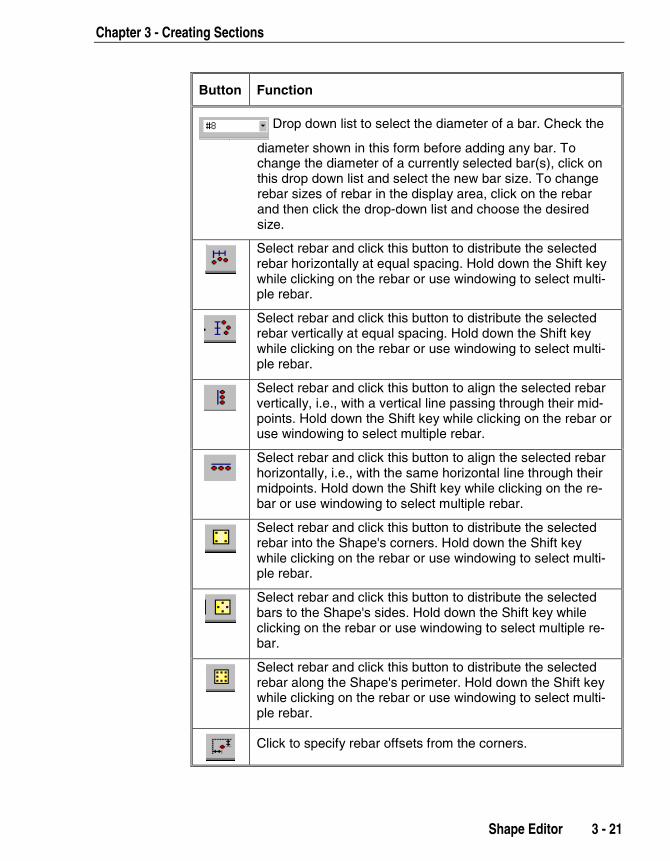
Drop down list to select the diameter of a bar. Check the
diameter shown in this form before adding any bar. Tochange the diameter of a currently selected bar(s), click onthis drop down list and select the new bar size. To changerebar sizes of rebar in the display area, click on the rebarand then click the drop-down list and choose the desiredsize.
Select rebar and click this button to distribute the selectedrebar horizontally at equal spacing. Hold down the Shift keywhile clicking on the rebar or use windowing to select multi-ple rebar.
Select rebar and click this button to distribute the selectedrebar vertically at equal spacing. Hold down the Shift keywhile clicking on the rebar or use windowing to select multi-ple rebar.
Select rebar and click this button to align the selected rebarvertically, i.e., with a vertical line passing through their mid-points. Hold down the Shift key while clicking on the rebar oruse windowing to select multiple rebar.
Select rebar and click this button to align the selected rebarhorizontally, i.e., with the same horizontal line through theirmidpoints. Hold down the Shift key while clicking on the re-bar or use windowing to select multiple rebar.
Select rebar and click this button to distribute the selectedrebar into the Shape's corners. Hold down the Shift keywhile clicking on the rebar or use windowing to select multi-ple rebar.
Select rebar and click this button to distribute the selectedbars to the Shape's sides. Hold down the Shift key whileclicking on the rebar or use windowing to select multiple re-bar.
Select rebar and click this button to distribute the selectedrebar along the Shape's perimeter. Hold down the Shift keywhile clicking on the rebar or use windowing to select multi-ple rebar.
Click to specify rebar offsets from the corners.

SectionBuilder Users Manual
3 - 22 Shape Editor
Button Function
Click to specify minimum spacing between rebar.
Click to display/hide the rebar diameter/size caption.
Click to show or hide the plate lines defined for the Shape
Click to turn Snap to Grid on and off.
Click to display or hide gridlines in the display area.
Click to reset the entire view for best fit after using the ZoomOut and Zoom In buttons.
Click this button and the left mouse button to zoom out, de-creasing the size of the Shape in the display area.
Click this button and the left mouse button to zoom in, in-creasing the size of the Shape in the Display area.
Click to add the current output (for the Shape shown) to thereport.
Click to print this Shape only.
Add Rebar Using the Rebar CalculatorThe previous section lists the toolbar buttons available in Shape Editor toadd, delete, arrange and align the rebar "manually." This section de-scribes using the Rebar Calculator to easily add multiple rebar in a singleoperation. After the rebar have been added using the Rebar Calculator,use the other toolbar buttons to make adjustments or changes.
1. With a Shape displayed in the Main Working Area, activate theShape Editor using one of the following methods:
Select the Section menu > Edit Current Shape command.
Click the Edit Current Shape button .
Double click on the Shape to be edited in the Main Working Area.
Chapter 3 - Creating Sections
Shape Editor 3 - 23
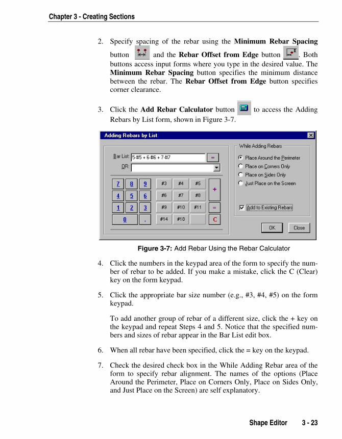
2. Specify spacing of the rebar using the Minimum Rebar Spacing
button and the Rebar Offset from Edge button . Bothbuttons access input forms where you type in the desired value. TheMinimum Rebar Spacing button specifies the minimum distancebetween the rebar. The Rebar Offset from Edge button specifiescorner clearance.
3. Click the Add Rebar Calculator button to access the AddingRebars by List form, shown in Figure 3-7.
Figure 3-7: Add Rebar Using the Rebar Calculator
4. Click the numbers in the keypad area of the form to specify the num-ber of rebar to be added. If you make a mistake, click the C (Clear)key on the form keypad.
5. Click the appropriate bar size number (e.g., #3, #4, #5) on the formkeypad.
To add another group of rebar of a different size, click the + key onthe keypad and repeat Steps 4 and 5. Notice that the specified num-bers and sizes of rebar appear in the Bar List edit box.
6. When all rebar have been specified, click the = key on the keypad.
7. Check the desired check box in the While Adding Rebar area of theform to specify rebar alignment. The names of the options (PlaceAround the Perimeter, Place on Corners Only, Place on Sides Only,and Just Place on the Screen) are self explanatory.

SectionBuilder Users Manual
3 - 24 Shape Editor
In the event that the current corner clearance and minimum barspacing specified in Step 2 are incompatible with the alignmentchoice, SectionBuilder will place as many bars as possible in thespecified alignment and then place the remaining bars adjacent to theShape for manual placement. Depending on the number of rebar notaligned, it may be advantageous to delete the rebar that have beenadded and return to Step 2 to specify new values for the clearanceand minimum spacing.
8. Indicate if the rebar are to be added to existing rebar (check the Addto Existing Rebar check box) or replace existing rebar (uncheck theAdd to Existing Rebar check box).
Delete RebarThe rebar already added on the Shape can be deleted at any stage as fol-lows:
1. Select the rebar that you want to delete by clicking on them or win-dowing over them in the display area of the Shape Editor.
2. Click the Delete Selection button or the Delete key on the key-board.
3. Click the Accept Change button to update the properties.
Change the Diameter of the RebarTo change the diameter of the rebar:
1. Select the rebar to be changed by clicking on them or windowingover them in the display area of the Shape Editor.
2. Select the new diameter from the drop-down list .
3. Click the Accept Change button to update the properties.
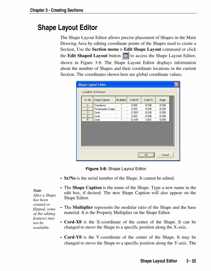
Chapter 3 - Creating Sections
Shape Layout EditorThe Shape Layout Editor allows precise placement of Shapes in the MainDrawing Area by editing coordinate points of the Shapes used to create aSection. Use the Section menu > Edit Shape Layout command or clickthe Edit Shaped Layout button to access the Shape Layout Editor,
shown in Figure 3-8. The Shape Layout Editor displays informationabout the number of Shapes and their coordinate locations in the currentSection. The coordinates shown here are global coordinate values.
Figure 3-8: Shape Layout Editor
Sr/No is the serial number of the Shape. It cannot be edited.
The Shape Caption is the name of the Shape. Type a new name in theedit box, if desired. The new Shape Caption will also appear on theShape Editor.
The Multiplier represents the modular ratio of the Shape and the basematerial. It is the Property Multiplier on the Shape Editor.
Cord-X0 is the X-coordinate of the center of the Shape. It can bechanged to move the Shape to a specific position along the X-axis.
NoteAfter a Shapehas beenrotated orflipped, someof the editingfeatures maynot beavailable.
Shape Layout Editor 3 - 25
Cord-Y0 is the Y-coordinate of the center of the Shape. It may bechanged to move the Shape to a specific position along the Y-axis. The

SectionBuilder Users Manual
3 - 26 Add Fillets
X and Y coordinates are in respect to the coordinate origin shown asthe X –Y (not the 2-3 system) on the main working area.
The Angle is the angle of the Shape with respect to the X-axis meas-ured in the counterclockwise direction. The angle can be specified toalign a Shape at any orientation between 0 and 360 degrees. Vertical orhorizontal orientation of a Shape can be set or changed using the flipand rotate buttons on the toolbar.
Add FilletsFillets of user-specified radii can be added to selected Shapes. The datarequired to add a fillet to a Shape is the point where you want to add thefillet, the radius of the fillet and the number of points on the curve of thefillet. To add a fillet to a Shape:
1. Select the Shape to which you want to add the fillet in the MainDrawing Area.
2. Click the Section menu > Add Fillets command or the Add Fillet at
Selected Point button to access the Add Fillet at Shape Pointform. The coordinate points (nodal points) of the selected Shape willbe displayed on the Main Working Area. If you have selected aparametric or a database shape, SectionBuilder will prompt tochange it to a polynomial.
3. From the drop-down list, select the node point to which you want toadd the fillet.
4. Specify the radius of the fillet you intent to add and the number ofpoints on the curve of the fillet. The number of points will determinethe smoothness of the curve. More points will result in a smoothercurve. The program will automatically calculate the included angle atthe selected point for the given radius.
5. Click OK. The specified fillet will be added to the selected Shape onthe Main Working Area.
Note:Adding afillet to aparametricShape (i.e.,libraryShape) converts theShape to apolynomialthat can nolonger bemodifiedparametri-cally.

Chapter 3 - Creating Sections
Merge Shapes 3 - 27
Merge ShapesTwo editable Shapes (see Table 3-1) with the same material propertiesthat have a common edge or that overlap can be merged, with the fol-lowing exceptions.
Holes cannot be merged with solid Shapes.
Holes cannot be merged with holes.
No more than two Shapes can be merged at a time.
To merge two Shapes:
1. Select the two Shapes to be merged.
2. Click the Section menu > Merge Shapes Using Mesh command orthe Attempt to Merge Shapes Using Mesh button or the Sec-tion menu > Merge Shapes Using Outline command or the At-
tempt to Merge Shapes Using Outline button .
3. Verify that the two Shapes have been successfully merged by dis-playing the Shape outline or as a filled Shape using the buttons iden-tified in Table 3-2.
When you merge two Shapes, the new Shape takes on the properties andproperty assignment of the first Shape selected for merging.
Table 3-2 Buttons to Display Shape Outlines and Fills
Displays the Shape outline only.
Displays the Shape as a solid.
Displays the solid Shape as well as the mesh used tocompute J.
Displays only the mesh used to compute J.

SectionBuilder Users Manual
3 - 28 Add Holes
If the final merged Shape is not as expected, or as it should be, try one ofthe following:
a. Undo the task using the Undo button , and try again.
b. Accept the new Shape (i.e., click the Accept Changes and RefreshWindows button). Select the Shape and click the Edit CurrentShape Points button to display the nodal points of the merged
Shape. Select the nodal points and drag them with the mouse to thedesired location.
Add HolesUse the following procedure to create a hole in a Shape or Section:
1. Add a Shape (first Shape). By default, the Shape Type is Solid untilyou change.
2. Add a Shape whose size is equal to the size of the hole (secondShape).
3. Move the second Shape to the place where the hole is to be created(generally inside the first Shape). To move the Shape, select it anddrag it with the mouse or use the arrow keys on the keyboard.
4. Double click on the second Shape or use the Edit Current Shapebutton to open the Shape Editor. Set the Shape Type to Hole
.
5. Click OK to accept the change and return to the main workspace.
Verify that the hole has been created properly by making the "solid" por-tion of the Shape visible using any of the buttons identified in Table 3-2.
Edit a Shape Using the MouseThe geometry of a Shape is defined by a number of lines/curves con-necting nodes. Nodes are defined by coordinates with respect to some

Chapter 3 - Creating Sections
reference axes. In addition to modifying the coordinates of the nodes us-ing the Shape Editor, a Shape can be changed using the mouse. Figure 3-9 illustrates a Shape modified using the mouse.
Figure 3-9: Shape Editing by Moving Nodes (top right node moved)
To move the node of a Shape using the mouse:
1. Select the Shape to be modified.
2. Click the Section menu > Edit Current Shape Points command orthe Edit Current Shape Points button to highlight the nodal
points of the Shape on the screen.
3. Select a node and drag it to the desired location. Repeat with addi-tional nodes as necessary to achieved the desired Shape.
Edit Shapes using Toolbar ButtonsDepending on the geometry of a Section, the arrangement of the Shapesthat make up the Section may vary from very simple to relatively com-plex. To handle all such situations, SectionBuilder has a large number oftoolbar buttons for aligning, flipping, rotating and stacking the Shapes.Refer to the "Toolbars" and "Menus" sections in Chapter 2 for a descrip-tion of the various toolbar functions to accomplish Shape alignment.
It is important to note that in SectionBuilder Stacking is performed on
Note:First selecta Shape,then clickthe desiredShapealignmenttool.
Edit Shapes using Toolbar Buttons 3 - 29
the basis of the relative location of the Shapes, whereas the alignment isperformed on the basis of the first Shape selected, in the order of selec-tion.

SectionBuilder Users Manual
3 - 30 Computation of Sectional Properties
Two important notes about rotating and flipping: If you want to rotate as well as flip a Shape, do the rotation first and
then the flipping. The opposite order may create some unexpected re-sults.
After a Shape has been rotated or flipped, some of the editing featuresmay not be available.
Rotate Entire Section
The Rotate Entire Section tool activates the Rotate Section form.Use that form to specify the angle of rotation for the entire Section. Theoptions available for rotation are as follows:
Rotate to Align with Principal Axis: Rotates the active Section toalign it with its Principal Axis. If the Section’s current orientation isalong the Principal Axis, no rotation takes place.
Rotate by Angle about Centroid of the Section: Rotates the Sectionabout its centroid at a user-defined angle. The angle may be specifiedin degrees. Positive angles define rotation in the counterclockwise di-rection, while negative angles result in clockwise rotations.
Rotate by Angle about a Specified Point: Rotates the Section aboutany user specified point defined in terms of the x and y coordinate. Theangle is specified in degrees. Specify the angle of rotation and thepoint about which the rotation is required. Positive angles define rota-tion in the counterclockwise direction while negative angles result inclockwise rotations.
Computation of Sectional Properties To improve the overall performance of the program, the Section proper-ties are computed using two separate commands.
Use the Results menu > Compute Basic Properties command or the
Compute Basic Properties button (or Click F7) to compute all
the properties except the Torsional Constant J and Shear Area.

Chapter 3 - Creating Sections
Computation of Sectional Properties 3 - 31
Use the Results menu > Compute Torsional Constant J command or
the Compute Torsional Constant and Shear Area button (or
Click F8) to compute J.
The process for computing Torsional Constant J and Shear Area is itera-tive and generally time consuming, which slows down the interactiveprocess. This becomes more important when the user has selected theoption to compute properties automatically after each modification (Op-tions menu > View Options command). Moreover these properties maynot be required as often as the rest of the properties in the practical de-sign world.
The geometric properties for closed Shapes are computed using the pro-cedures explained in Chapter 4 of this manual. The basic properties com-puted by the program are summarized in Table 3-3.
IMPORTANT NOTE
All of the geometric properties of the Section are computed in terms of the
base material defined for the Section. For example, assume a Section is
made up of Shapes of normal reinforced concrete (including reinforcing)
and hot rolled steel. If the base material defined for the entire Section is
ordinary concrete (the same as the first Shape), the properties of other
Shapes are converted into equivalent ordinary concrete Shapes. This pro-
cess of transformation from materials of different properties into a single
common base material enables us to treat the Transformed Section as a
Section of homogeneous materials. The equivalent property in terms of
base material is computed using the Modular Ratio or the ratio of the
modulus of elasticity of the base material, to that of the material of the
Shape that needs to be transformed.

SectionBuilder Users Manual
3 - 32 Computation of Sectional Properties
Table 3-3 Summary of Properties Computer by SectionBuilder
Property Specific Data Type
Section Size and Location: Total Width Total Height Center Xo, the location of the centroid with
respect to the coordinate origin Center Yo, the location of the centroid with
respect to the coordinate origin
Centroids of the Section withrespect to section bounda-ries:
X-bar (Right) X-bar (Left) Y-bar (Top) Y-bar (Bottom)
Gross Cross Sectional Area: Area (Ax)
Second Moments of Inertia ofthe Gross Area:
Inertia (I33) Inertia (I22) Inertia (I32)
Section Modulii: Modulus S3 (Top) Modulus S3 (Bot) Modulus S2 (Left) Modulus S2 (Right)
Principal Radius of Gyrations: Gyration (r3) Gyration (r2)
Principal Moments of Inertiaand Angles:
Principal Angle (θ) Inertia (I33’) Inertia (I22’)
Torsional Constant: Torsional J
Effective Shear Areas: Shear Area A3 Shear Area A2
Plastic Section Modulii: Plastic Modulus (Z3) Plastic Modulus (Z2)

Chapter 3 - Creating Sections
Design of Sections 3 - 33
Design of SectionsIn addition to defining and computing Section properties, SectionBuildercan be used to design structural Sections. The interaction curves, interac-tion surfaces, moment-curvature curves, and stress plots are based onuser-specified design codes and specifications. At present, the programsupports various standard codes of practice for steel and concrete Shapes,including AISC and ACI. Options related to design of stress-straincurves are provided. The Section capacities are computed using the firstprinciple, and adjusted capacity factors are specified in the design code.
Chapter 4 explains SectionBuilder's Capacity Calculations and Designcapabilities.
Create a Report Using the Report Creation WizardAs the name indicates, the report creation wizard helps the user to gener-ate and format the report in a systematic way. When you click the Re-sults menu > Report Creation Wizard command or the Report Crea-
tion Wizard button , the Report Creation Wizard form shown in Fig-
ure 3-10 appears:
Figure 3-10: Report Creation Wizard
1. In the Select Sections to be Included area of the form, check thecheck boxes of the sections to be included in the report.

SectionBuilder Users Manual
3 - 34 Preview the Report
2. In the Output Items to be Included area of the form, check the checkboxes of the items to be included in the report.
It is possible to select different items for different Sections. For ex-ample, items such as project information, calculation procedures, andso forth can be selected for the first Section, and then for the remain-ing Sections, you can choose to print only the results, assuming thatthe project information, calculation procedures and so on are consis-tent across all Sections in the Section File.
3. After the required items have been selected, click the Generate Re-port button to finish the report generation process.
Preview the ReportClick the Results menu > Preview Current Report command or the
Preview Current Report button to preview the report before send-
ing it for final printing. Figure 3-11 shows a preview of a sample report.Various navigational buttons (first page, next page, page up / down andso forth) are provided to view different report pages. Clicking the leftand right mouse button on the preview window will zoom in and out ofthe view respectively.
To print the report, click the Print button in the upper left-hand corner ofthe report previewer.
To close the previewer without printing, click Close button near the mid-dle of the toolbar at the top of the screen.

Chapter 3 - Creating Sections
Print the Current View 3 - 35
Figure 3-11: Previewing the Report
Print the Current ViewAny graphic view currently displayed on the screen can be sent forprinting by clicking the File menu > Print Current Section command
or the Print Current Report button. This is useful for quick print-
ing of the current section without using the Report Generation Wizard.
The current view can be added to the report by clicking the Add Cur-rent View to the Report button . The report can then be printed
later.

SectionBuilder Users Manual
3 - 36 View Options
View OptionsUse the Options menu > View Options command to specify optionsrelated to display color, drawing scales and auto refreshing on the ViewTab of the Options and Preferences form.
Display ColorDifferent colors can be assigned to different Shapes comprising a Sec-tion. Color assignment apply to both on-screen display and printed out-put, assuming the output is generated using a color printer. The three op-tions for defining color-coding are as follows:
Color Based on Shape Number. Each Shape in a Section will displayin a different color, regardless of the material properties assigned to theShape.
Color Based on Stress Strain Curve. Each type of stress-strain curvewill display in a different color. Use this option to display Shapes as-signed the same stress-strain curve in the same color.
Color Based on Material. Each type of material (i.e., steel, concreteand hollow Shapes) will display in a unique color. Use this option todisplay Shapes assigned the same material type in the same color. Bothborder and fill colors can be specified for this option.
NOTE: If two or more overlapping Shapes have the same Property Mul-tiplier but different stress-strain relationship, it is possible that bothshapes will displayed in the same color, signifying that one of the mate-rials has superseded the other. In such a case, increase or decrease theModulus of Elasticity of either material slightly. The material with thehigher Modulus of Elasticity will retain its mesh and the other materialwill not be shown in the area of overlap.
Drawing ScalesAll Shapes added from a Shape library are drawn in true proportions onscreen as well as when printed. SectionBuilder automatically scales thedrawing area to fit the Shapes.
Chapter 3 - Creating Sections
View Options 3 - 37
To create extra space around the Section or Shape drawing, specify thefixed drawing area larger than necessary.
Auto RefreshSectionBuilder can automatically refresh graphic views and results afterchanges have been made in the Main Drawing Area. Three options areavailable.
Refresh Graphic View. The cross-section displayed in the MainWorking Area will automatically be updated following any changesto the Shapes comprising the Section.
Recompute Basic Properties. The data displayed in the Propertiesarea of the SectionBuilder screen will automatically update followingany changes to the dimensions or property assignments.
Recompute Additional Properties. SectionBuilder will automati-cally recompute the additional properties following any changes tothe Shapes comprising the Section.

4- 1
Chapter 4
Designing Sections
Introduction In addition to defining Sections and computing their geometric proper-ties, SectionBuilder can calculate Section capacities, plot the resultsgraphically, and quickly and easily generate reports that include the inputdata, the output data, and the graphical presentation.
The main topics presented in this chapter describe plotting the combinedstresses caused by various combinations of P, Mx and My (or M2 and M3
as used in ETABS and SAP2000) and Shear and Torsional stresses; andgenerating interaction curves and surfaces and viewing the generationprocess. In addition, the steps required to plot moment-curvature curvesare also described.
It is assumed that the user is familiar with the basic concepts of structuralconcrete mechanics (especially the structural interpretation of the designparameters) and structural analysis results.
CSISectionBuilder

Chapter 4 -Designing Sections
4 - 2 Compute Section Capacity
Compute Section Ca The following assucomputes Section c
Basic Assumpt All component
dance with thewithout bucklimean that the e
SectionBuilder computes the
each Shape based on the ma
provided for that Shape. The c
ming the contribution of each
Capacity is NOT COMPUTED
ing geometric properties. This
ties and stress-strain curves f
tionBuilder does compute the
fore deciding which part of wh
or compression). A Shape mig
Entirely under compres
Entirely under tension
Under compression and
After deciding the prevailing s
stress-strain relationship is us
Shape is computed using rigo
Shapes in the Section. Finally
summing the capacity of each
viewed graphically using the I
VERY IMPORTANT
capacity of a Section using the mesh derived for
terial properties and the stress-strain relationship
apacity of the entire Section is computed by sum-
individual Shape. This means that the Section
based on equivalent Section as used for comput-
is also the reason for specifying separate proper-
or individual Shapes of a Section. However, Sec-
neutral axis and centroid for the entire Section be-
ich Shape falls in which stress zone (under tension
ht be:
sion
tension
tress condition in each Shape, the corresponding
ed to compute its capacity. The capacity of each
rous first principles. This process is repeated for all
, the total capacity of the Section is computed by
Shape (rebar included). This process can be
nteraction Surface Generation Viewer.
pacitymptions and procedures apply when SectionBuilderapacities.
ionss of the Section are capable of deformation in accor- stress-strain curve defined for them (for each Shape),ng or without local failure. This does not necessarilyntire Section has to be plastic. It is possible that some

SectionBuilder User's Manual
Compute Section Capacity 4 - 3
parts of the Section are made from separate Shapes with their stress-strain curve defined in such a way that the Shape fails even beforereaching its yield strain. This assumption signifies that the Sectioncapacity is computed using the stress-strain curves defined for eachSection component.
The assumption of strain compatibility is valid across various com-ponents of the Section. In other words, a perfect bond or connectionexists between all components of the Section.
It is not necessary to assume that plane sections remain plane afterdeformation. A nonlinear strain distribution across the Section depthmay be specified. In fact, it is possible to define separate stress-strainrelationships for different parts of the same Shape, by dividing theShape into Sub-Shapes with desired stress-strain properties.
Design Calculation Procedure The Section to be designed can be defined in terms of individual Con-crete Shapes, Steel Reinforcing, Pre-Stressing Strands, Steel Shapes or acombination of these types of Shapes. The stress-strain relationship foreach material is defined separately. In addition, different stress-strain re-lationship can be defined for the same material (e.g., different Shapes de-fined using the same material can be assigned different stress-strain rela-tionships). After the Section has been defined, it is automatically meshedinto quadrilateral and triangular elements. A strain distribution for theShape is then assumed based on a specific angle and depth of the neutralaxis. For the assumed strain distribution, the strain in the individualmeshed elements is computed. For that strain, stress in the element isobtained from the appropriate stress strain curve defined for the materialat the element location. The stress within each element is then integratedusing the appropriate Shape function. Then the resulting stresses for theentire Section are summed to determine the axial section capacity. Asimilar approach has been used to determine the moment capacity of twoorthogonal axes.
This theoretical capacity is then modified using the appropriate capacityreduction factors (based on the design code).
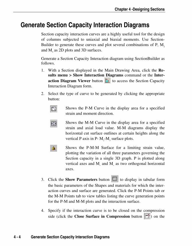
Chapter 4 -Designing Sections
4 - 4 Generate Section Capacity Interaction Diagrams
Generate Section Capacity Interaction Diagrams Section capacity interaction curves are a highly useful tool for the designof columns subjected to uniaxial and biaxial moments. Use Section-Builder to generate these curves and plot several combinations of P, M2
and M3 as 2D plots and 3D surfaces.
Generate a Section Capacity Interaction diagram using SectionBuilder asfollows.
1. With a Section displayed in the Main Drawing Area, click the Re-sults menu > Show Interaction Diagrams command or the Inter-action Diagram Viewer button to access the Section CapacityInteraction Diagram form.
2. Select the type of curve to be generated by clicking the appropriatebutton:
Shows the P-M Curve in the display area for a specifiedstrain and moment direction.
Shows the M-M Curve in the display area for a specifiedstrain and axial load value. M-M diagrams display thehorizontal cut surface outlines at certain heights along thevertical P axis in P- M2-M3 surface plots.
Shows the P-M-M Surface for a limiting strain value,plotting the variation of all three parameters governing theSection capacity in a single 3D graph. P is plotted alongvertical axes and Mx and My as two orthogonal horizontalaxes.
3. Click the Show Parameters button to display in tabular form
the basic parameters of the Shapes and materials for which the inter-action curves and surface are generated. Click the P-M Points tab orthe M-M Points tab to view tables listing the curve generation pointsfor the P-M and M-M plots and the interaction surface.
4. Specify if the interaction curve is to be closed on the compression
side (click the Close Surface in Compression button ) on the

SectionBuilder User's Manual
Generate Section Capacity Interaction Diagrams 4 - 5
tension side (click the Close Surface in Tension button ) or on
both sides (click both buttons). Note that closing the curve on thetension side may result in a shift of the curve because the last inte-gration point will be on the vertical axis. This may not be the actualbehavior of the Section. The shift is significant in cases with un-symmetrical sections.
5. Click the Limiting Strain button to define the Maximum Strain
on the Limiting Face of the Section for generating the curve. Realis-tic strain values will produce realistic results; unrealistic strain valueswill produce results with no meaning.
6. Select a capacity reduction factor from the drop-down list:
a. With phi factors (capacity reduction factors applied)
b. Without phi factors
c. Without phi factors and Fy increased by 25%
7. Customize the display depending on the type of capacity plot or sur-face selected in Step 2:
a. P-M diagram (P-M Curve button ). Select one of the fol-
lowing:
Plot the P-Mx Curve (angle = 0)
Plot the P-My Curve (angle = 90)
Select or specify the angle of neutral axis, from 0 to 360.
b. M-M diagrams (M-M Curve button ). Select a Pu value
from the drop-down list.
c. Interaction Surface (P-Mx-My button ). Color coding of the
various P-Mx-My parameters is used to display the InteractionSurface. To “read” the display, compare the color used in the
IMPORTANTNOTEMake sure thatthe maximumstrain value isrealistic.Unrealisticstrain valueswill generateresults with nomeaning.
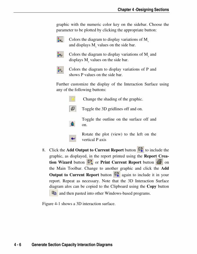
Chapter 4 -Designing Sections
4 - 6 Generate Section Capacity Interaction Diagrams
graphic with the numeric color key on the sidebar. Choose theparameter to be plotted by clicking the appropriate button:
Colors the diagram to display variations of Mx
and displays Mx values on the side bar.
Colors the diagram to display variations of My anddisplays My values on the side bar.
Colors the diagram to display variations of P andshows P values on the side bar.
Further customize the display of the Interaction Surface usingany of the following buttons:
Change the shading of the graphic.
Toggle the 3D gridlines off and on.
Toggle the outline on the surface off andon.
Rotate the plot (view) to the left on thevertical P axis
8. Click the Add Output to Current Report button to include the
graphic, as displayed, in the report printed using the Report Crea-tion Wizard button or Print Current Report button on
the Main Toolbar. Change to another graphic and click the Add
Output to Current Report button again to include it in your
report. Repeat as necessary. Note that the 3D Interaction Surfacediagram alos can be copied to the Clipboard using the Copy button
and then pasted into other Windows-based programs.
Figure 4-1 shows a 3D interaction surface.

SectionBuilder User's Manual
Generate Section Capacity Interaction Diagrams 4 - 7
Figure 4-1: A 3D Interaction Surface
View the Interaction Surface Generation Process Generating interaction curves and surfaces requires a significant amountof mathematical computations. The process requires that the Sectionproperties be calculated several times. With a Section displayed in theMain Drawing Area, click the Generate Interaction Surface button
on the Main Toolbar (not on the Capacity Interaction Diagram
form) to activate the Interaction Surface Generation viewer.
This viewer allows you to view the complete 3D interaction surface gen-eration process as the location of neutral axis changes for each cycle ofcalculation. The user has control over the level of refinement, which canbe achieved by setting increment angles, number of points on the curveand slice thickness.
Because of repeated cycles of computations, the process to generate thecomplete 3D surface generally takes time. However, once started, theprocess can be stopped (interruppted) at any time by clicking the Cancel
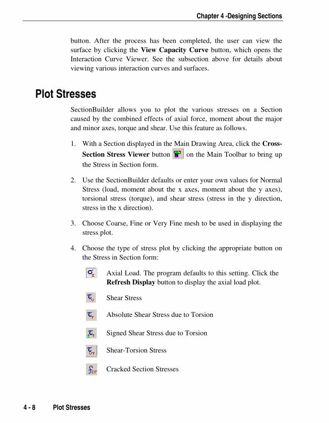
Chapter 4 -Designing Sections
4 - 8 Plot Stresses
button. After the process has been completed, the user can view thesurface by clicking the View Capacity Curve button, which opens theInteraction Curve Viewer. See the subsection above for details aboutviewing various interaction curves and surfaces.
Plot Stresses SectionBuilder allows you to plot the various stresses on a Sectioncaused by the combined effects of axial force, moment about the majorand minor axes, torque and shear. Use this feature as follows.
1. With a Section displayed in the Main Drawing Area, click the Cross-
Section Stress Viewer button on the Main Toolbar to bring up
the Stress in Section form.
2. Use the SectionBuilder defaults or enter your own values for NormalStress (load, moment about the x axes, moment about the y axes),torsional stress (torque), and shear stress (stress in the y direction,stress in the x direction).
3. Choose Coarse, Fine or Very Fine mesh to be used in displaying thestress plot.
4. Choose the type of stress plot by clicking the appropriate button onthe Stress in Section form:
Axial Load. The program defaults to this setting. Click theRefresh Display button to display the axial load plot.
Shear Stress
Absolute Shear Stress due to Torsion
Signed Shear Stress due to Torsion
Shear-Torsion Stress
Cracked Section Stresses

SectionBuilder User's Manual
Plot Stresses 4 - 9
Color coding of the stress distribution is used to display the plot. To“read” the display, compare the color used in the graphic with thenumeric color key on the sidebar.
5. If desired, display the stress distribution along a specified line of the
Section by clicking the Show Curve Guides button and the
Show Stress Curves button or the Show Stress Curves Out-
line button . Use the mouse to move the guides over the graphic
display to the desired location. Click the Refresh Display button.
6. Click the Add Output to Current Report button to include thegraphic as displayed in the report printed using the Report CreationWizard button or Print Current Report button on the
Main Toolbar. Change to another stress plot and click the Add Out-
put to Current Report button again to include another plot in
your report. Repeat as necessary.
Use the following buttons to adjust the display:
Show dimensions and centroidal axis on the section.
Display the plot on a black background (default).
Display the plot on a white background.
Zoom in and out of the Section display.
The Figures 4-2 and 4-3 show some examples of stress plots in a Section.

Chapter 4 -Designing Sections
4 - 10 Plot Stresses
Figure 4-2: Axial Stress Plot
Figure 4-3: Absolute Shear Stress Plot of Torsion

SectionBuilder User's Manual
Prestress Check 4 - 11
Prestress Check SectionBuilder provides an effective tool for checking stresses on aprestressed Section. Use this feature as follows:
1. With a Section displayed in the Main Drawing Area, click the Cross-
Section Stress Viewer for PS button on the Main Toolbar to
bring up the Prestress Check form.
2. Specify values for load, moment about the x axes, and moment aboutthe y axes.
Specify a prestress Force in kips and the location of the force (CenterX and Center Y relative to the Section centroid). The location of theprestress force will be identified in the display by a "bullseye" .Click on it and drag it with the mouse to change the values for Cen-ter X and Center Y graphically. The display automatically updateswith every movement of the force location. Color coding of thestress distribution is used to display the plot. To “read” the display,compare the color used in the graphic with the numeric color key onthe sidebar.
3. Choose Coarse, Fine or Very Fine mesh to be used in displaying thestress plot.
4. Click the Refresh Display button to display the plot based on the in-put parameters.
5. If desired, display the stress distribution along a specified line of the
Section by clicking the Show Curve Guides button and the
Show Stress Curves button or the Show Stress Curves Out-
line button . Use the mouse to move the guides over the graphic
display to the desired location. Click the Refresh Display button.
6. Click the Add Output to Current Report button to include thegraphic as displayed in the report printed using the Report CreationWizard button or Print Current Report button on the
Main Toolbar. Repeat Steps 2 through 6 and click the Add Output
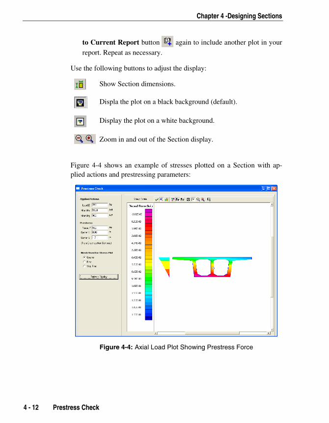
Chapter 4 -Designing Sections
4 - 12 Prestress Check
to Current Report button again to include another plot in your
report. Repeat as necessary.
Use the following buttons to adjust the display:
Show Section dimensions.
Displa the plot on a black background (default).
Display the plot on a white background.
Zoom in and out of the Section display.
Figure 4-4 shows an example of stresses plotted on a Section with ap-plied actions and prestressing parameters:
Figure 4-4: Axial Load Plot Showing Prestress Force
SectionBuilder User's Manual
Plotting Moment-Curvature Curves SectionBuilder allows you to plot moment-curvature curves at a speci-fied neutral axis angle of a Section for a given axial load. These curvesare intended primarily for Reinforced Concrete Sections. Use this featureas follows:
1. With a Section displayed in the Main Drawing Area, click the Mo-
ment-Curvature Viewer button to access the Moment Curva-
ture Diagram form.
2. Specify a maximum strain (i.e., strain at failure) and the increments
Note: The compu-tation re-quired to plota moment-curvaturecurve cantake sometime. Pleasebe patient.
Plotting Moment-Curvature Curves 4 - 13
to be used in plotting the strain.
3. Specify the failure criterion by checking the appropriate check box:
a. Maximum strain is reached
b. Any part of section fails
c. All parts of section fail
d. The first rebar fails
e. Selected Section part fails. Choose a section part from the drop-down list. If the Section is a single Shape, the Section will be theonly option.
4. Specify the section angle.
5. Specify the axial load. Any value of axial load can be specified, in-cluding zero.
6. Click the Generate button. Strain values display on the status bar asSectionBuilder completes the computation. When complete, Sec-tionBuilder displays values for Yield Moment, Yield Curve, Maxi-mum Moment, and Maximum Curvature in the Results area of theform.
7. Click the Add Output to Current Report button to include the
graphic as displayed in the report printed using the Report Creation

Chapter 4 -Designing Sections
4 - 14 Plotting Moment-Curvature Curves
Wizard button or Print Current Report button on the
Main Toolbar. Repeat Steps 2 through 6 to include another plot inyour report. Repeat as necessary.
To stop the calculation process, click the Cancel button (lower left por-tion of the form).
To close the Moment Curvature Diagram form, click the Close button(upper right corner of the form).
Figure 4-5: Moment-Curvature Curve Plot

A- 1
Appendix A
Managing Section Files and Shape Libraries
OverviewThis Appendix describes various types of files used and created by Sec-tionBuilder. Some of these files are for the internal use of the program(called Program Files) and some are created and managed by the user(called User Files).
Program FilesProgram files are installed automatically in appropriate directories duringprogram installation. Do not delete, move, modify or edit these files inany way. Program files consist of two categories: standard shape libraryfiles and program data files.
Standard Shape Library FilesStandard shape library files contain editable parametric Shapes andnon-editable Shapes from various steel databases. Some of these files
CSISectionBuilder
SectionBuilder Users Manual
A - 2 Overview
are installed in the program directory and some in the \Shape Li-braries subdirectory. These files have .csf and .lsd extensions.
Program Data FilesProgram data files contain material properties, unit conversion fac-tors, rebar sets and similar program data. All of these files are in-stalled in the program directory and have an .ssf extension.
User FilesUser files can be created, modified or deleted and consist of two types:section files and user-defined shape library files.
Section FilesSection files store the Sections. They can be saved and opened fromany directory on the hard disk and can be moved or copied usingstandard Windows file operations. Section files have a .csb extensionand are managed using the commands on the File menu.
User-Defined Shape Library File(s)As the name suggests, user-defined shape library files are created bythe user to organize the basic Shapes available in the standard shapelibrary files. After a user-defined library file has been created, it canbe used in the same way a standard Shape library file is used. User-defined shape libraries are managed using the toolbar buttons on theLibrary Viewer, which is used to add Shapes to the current Section.Details on how to use this toolbar are provided later in this Appen-dix.
The subsequent pages in this Appendix provide information on the con-tents of the files identified previously, and describe tools to create andmange these files.

Appendix A - Managing Section Files and Shape Libraries
Types of Shape Libraries A - 3
Types of Shape LibrariesSectionBuilder uses Shape Libraries to organize various standard and ba-sic Shapes that may have sub-shapes associated with them. The sub-shapes are the same as the parent Shape but they have different dimen-sions.
The Shape Libraries consist of two categories: standard shape librariesand user-defined shape libraries.
Standard Shape LibrariesStandard shape libraries consists of editable parametric shape files andnon-editable database files of code-specific steel shapes.
1. The editable parametric shapes are provided in the Basic Shape Li-braries and include the following types of shapes:
Basic Concrete Basic Steel Box Girder Bridge Pier Shear Wall Fillets and Chamfers
2. The non-editable code-specific steel shapes are consistent with thefollowing codes:
American Institute of Steel Construction (AISC) (inch and metricunits are in separate libraries)
Canadian Institute of Steel Construction (CISC) British Standard
User-Defined Shape LibrariesAs the name suggests, user-defined shape libraries are created by theuser. Frequently used shapes from the standard shape libraries can be or-ganized into these easy access user-defined libraries.
For example, if you often work with industrial projects involving steeltrusses and concrete columns, you may only require some of the readily

SectionBuilder Users Manual
A - 4 Working with Shape Libraries
available AISC-Metric shapes, such as L or C shapes (which are storedin the ACI-Metric Shapes library), and some concrete shapes such asrectangle or circular (which are stored in the basic concrete shapes li-brary). You can create a user-defined Shape library and copy the desiredshapes from the other libraries into it for easier frequent access. User-defined Shape libraries can be stored on any directory and can be addedto or removed from the main Library List at any time.
Do not confuse user-defined Shape libraries with Section files. Sectionfiles store Sections. User-defined Shape libraries store shapes selectedfrom other Shape libraries.
Working with Shape LibrariesTo access any of the Shape Libraries, click the Section menu > AddShape From Library command to bring up the View and Select LibraryShapes window. The toolbar buttons on View and Select Library Shapeswindow are enabled or disabled depending on the level of the librarywhere you are working. Please refer to the section entitled "Add Shapesfrom a Library" in Chapter 3 for an explanation of the procedures forviewing, selecting, and adding library shapes to Sections from a library.
The functions of the buttons in the View and Select Library Shapes win-dow are described as follows:
Button Function
Saves the current library with default or current name.
Saves the current library with a user specified name.
Saves all library files.
Moves back one level in the library
Moves down one level in the library.

Appendix A - Managing Section Files and Shape Libraries
Working with Shape Libraries A - 5
Button Function
Jumps to the top level (the main library list).
Adds the currently highlighted Shape to the mainworkspace and closes the View and Edit LibraryShapes window.
Opens a file selection window to select and open anew library file.
Removes the currently highlighted library from the cur-rent file.
Cuts the currently selected Shape and places it on theClipboard.
Copies the currently selected Shape and places it onthe Clipboard.
Pastes the Shape temporarily stored on the Clipboardto the current library.
Prints the Shapes list in the current library.
Starts SectionBuilder Help.
Create a User-Defined Shape LibraryTo create a user-defined library,
1. Click the Section menu > Add Shape From Library commandor the Add New Shape to current Section button to bring upthe View and Select Library Shapes form.
2. Click on <New Library> in the Main Library List of the Viewand Select Library Shapes form to highlight it, and then click theOpen Library button.
3. Specify the name of the library in the Create New Shape Libraryform and click the OK button. A blank library with no Shapeswill be displayed in the Library List.
4. Use the toolbar buttons, such as the Show Main Libraries button, to move through the available libraries of shapes and lo-
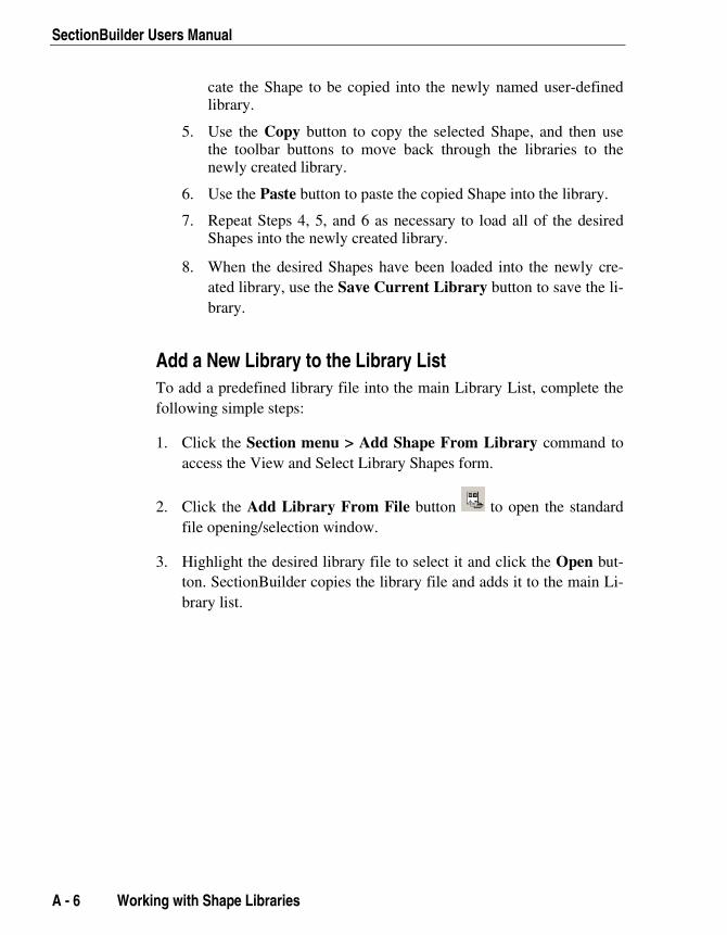
SectionBuilder Users Manual
A - 6 Working with Shape Libraries
cate the Shape to be copied into the newly named user-definedlibrary.
5. Use the Copy button to copy the selected Shape, and then usethe toolbar buttons to move back through the libraries to thenewly created library.
6. Use the Paste button to paste the copied Shape into the library.
7. Repeat Steps 4, 5, and 6 as necessary to load all of the desiredShapes into the newly created library.
8. When the desired Shapes have been loaded into the newly cre-ated library, use the Save Current Library button to save the li-brary.
Add a New Library to the Library ListTo add a predefined library file into the main Library List, complete thefollowing simple steps:
1. Click the Section menu > Add Shape From Library command toaccess the View and Select Library Shapes form.
2. Click the Add Library From File button to open the standardfile opening/selection window.
3. Highlight the desired library file to select it and click the Open but-ton. SectionBuilder copies the library file and adds it to the main Li-brary list.
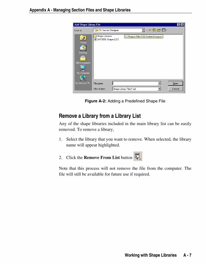
Appendix A - Managing Section Files and Shape Libraries
Working with Shape Libraries A - 7
Figure A-2: Adding a Predefined Shape File
Remove a Library from a Library ListAny of the shape libraries included in the main library list can be easilyremoved. To remove a library,
1. Select the library that you want to remove. When selected, the libraryname will appear highlighted.
2. Click the Remove From List button
Note that this process will not remove the file from the computer. Thefile will still be available for future use if required.