Information Interchange on Holographic Versatile Disc … · Information Interchange on Holographic...
138
Information Interchange on Holographic Versatile Disc (HVD) Recordable Cartridges – Capacity: 200 Gbytes per Cartridge ECMA-377 1 st Edition / May 2007
Transcript of Information Interchange on Holographic Versatile Disc … · Information Interchange on Holographic...

ECMA-377
Information Interchange on Holographic Versatile Disc (HVD) Recordable Cartridges – Capacity: 200 Gbytes per Cartridge
1st Edition / May 2007

COPYRIGHT PROTECTED DOCUMENT
© Ecma International 2007
patrick
Stamp

Ecma International Rue du Rhône 114
D ecma_377.doc
IH(CG
Sta
EC1st Ed
ndard
MA-377 ition / May 2007
CH-1204 Geneva T/F: +41 22 849 6000/01 www.ecma-international.org
nformation Interchange on olographic Versatile Disc HVD) Recordable artridges – Capacity: 200 bytes per Cartridge

.

NOTIFICATION AND DISCLAIMER
Ecma international draws attention to the possibility that the practice, use or implementation of this Ecma Standard or of parts thereof may involve the use of one or more Intellectual Property Rights, in particular such as a patent or a patent application.
Ecma International takes no position concerning the existence, evidence, scope of protection, validity or applicability of any or all of such Intellectual Property Rights, whether asserted by Ecma International members or others outside of the Ecma Standard development process worldwide. In particular, Ecma International does not identify any or all of such Intellectual Property Rights, does not evaluate the scope of protection and validity of any or all of such Intellectual Property Rights, and does not evaluate the question whether the practice, use or implementation of this Ecma Standard or of parts thereof does or does not make use of any or all of such Intellectual Property Rights. Furthermore, Ecma International does not assume – under any circumstances – any responsibility in this respect.
Ecma International informs that as of the date of approval of this Standard, Ecma International has received notice of Intellectual Property Rights. Implementers and users are cautioned that this may not represent the latest information which is available and are therefore strongly urged to consult the Ecma International website for further information.


Introduction
In October 2004 a group of Companies, known as the HVD Alliance, proposed to Ecma to develop a standard for the first member of a family of holographic media. Ecma adopted this project and Ecma Technical Committee TC44 was established for the standardization of holographic media.
This Standard ECMA-377 is the first standard for a Holographic Disk Cartridge (HDC).
This Ecma Standard has been adopted by the General Assembly in May 2007.


- i -
Table of contents
Section 1 - General 1
1 Scope 1
2 Conformance 1
2.1 Holographic Disk Cartr idge 1
2.2 Generat ing system 1
2.3 Receiving system 1
2.4 Compatibi l i ty statement 1
3 References 2
4 Definit ions 2
4.1 asymmetry 2
4.2 case 2
4.3 case reference plane 2
4.4 clamping zone 2
4.5 cover layer 2
4.6 Data Page 2
4.7 Data Page hologram 2
4.8 Data Page hologram pitch 2
4.9 data reading beam 2
4.10 data reading energy 2
4.11 data recording beam 2
4.12 data recording energy 2
4.13 disk reference plane 3
4.14 entrance surface 3
4.15 Error Correct ion Code (ECC) 3
4.16 f inal izing 3
4.17 f ix ing 3
4.18 format 3
4.19 hologram track 3
4.20 holographic disk 3
4.21 Holographic Disk Cartr idge (HDC) 3
4.22 holographic recording 3
4.23 packet 3
4.24 Permanent holographic information (Phi) type (of medium) 3

- ii -
4.25 pit 3
4.26 pit layer 3
4.27 pit t rack 3
4.28 pixel 3
4.29 recording layer 4
4.30 Reference Dr ive 4
4.31 Reference Pattern 4
4.32 Reed-Solomon code 4
4.33 spat ial l ight modulator 4
4.34 Specif ic Disk Information (SDI) 4
4.35 spindle 4
4.36 Sub-Page 4
4.37 substrate 4
4.38 Symbol 4
4.39 Sync Mark 4
4.40 t rack 4
4.41 t rack ing/addressing beam 4
4.42 t rack ing/addressing reading power 4
4.43 t rack pitch 4
4.44 User data Zone 4
4.45 write- inhibit hole 5
4.46 zone 5
5 Conventions and notations 5
5.1 Representat ion of numbers 5
5.2 Names 5
6 Acronyms 5
7 General description 5
8 General requirement 6
8.1 Environments 6
8.1.1 Operat ing environment 6
8.1.2 Storage environment 6
8.1.3 Transportat ion 7
8.2 Temperature shock 7
8.3 Safety requirements 7
8.4 Flammabil i ty 7

- iii -
9 Reference Drive 7
9.1 Optical system 7
9.2 Track ing and Addressing Channel 9
9.2.1 Track ing/addressing beam 9
9.2.2 Track ing/Addressing/SDI s ignals 9
9.3 Data Holographic Recording Channel 9
9.3.1 Recording beam 9
9.3.2 Spatial l ight modulator 10
9.4 Data Holographic Reading Channel 11
9.4.1 Read beam 11
9.4.2 Spatial l ight modulator 12
9.4.3 Photodetector array 12
9.5 Condit ions for measur ing the operat ional s ignals 12
9.5.1 Track ing, Addressing, Specif ic Disk Information 12
9.5.2 Data recording 12
9.5.3 Data reading 12
9.5.4 Normalized servo transfer funct ions 12
9.5.5 Rotat ion of the disk 12
9.6 Fix ing 12
Section 2 - Mechanical and physical characteristics 13
10 Dimensional, mechanical, and physical characteristics of the case 13
10.1 General descr ipt ion of the case 13
10.2 Reference axes and case reference plane 13
10.3 Case drawings 13
10.4 Dimensions of the case 13
10.4.1 Overal l dimensions 13
10.4.2 Locat ion hole 14
10.4.3 Alignment hole 14
10.4.4 Surfaces on Case Reference Plane P 15
10.4.5 Insert ion s lots and detent features 15
10.4.6 Gripper s lots 16
10.4.7 W rite- inhibit hole 16
10.4.8 Media ident i f icat ion sensor areas 16
10.4.9 Head and motor windows 17
10.4.10 Shutter 17
10.4.11 Shutter unlock ing levers 17
10.4.12 Slider for shutter opener 19
10.4.13 Feature to prevent insert ion into UDO, MO and W O dr ives 19
10.4.14 User label areas 19
10.5 Mechanical character ist ics 19
10.5.1 Mater ials 19
10.5.2 Mass 19

- iv -
10.5.3 Edge distort ion 19
10.5.4 Compliance 20
10.5.5 Shutter opening force 20
10.5.6 Levers unlock ing forces 20
10.6 Light-proof character ist ics 20
10.7 Drop test 20
10.8 Electro-stat ic discharge test 20
11 Dimensional, mechanical, and physical characteristics of the disk 34
11.1 General descr ipt ion of the disk 34
11.2 Reference axis and plane of the disk 34
11.3 Dimensions of the disk 35
11.4 Clamping Zone 35
11.5 Mechanical character ist ics 35
11.5.1 Mater ial 35
11.5.2 Mass 35
11.5.3 Moment of inert ia 35
11.5.4 Imbalance 35
11.5.5 Axial def lect ion 35
11.5.6 Axial accelerat ion 36
11.5.7 Radial runout 36
11.5.8 Radial accelerat ion 36
11.5.9 Til t 36
11.6 Optical character ist ics 37
11.6.1 Substrate 37
11.6.2 Metadata layer 37
11.6.3 Gap layer 1 37
11.6.4 Dichroic mirror layer 37
11.6.5 Gap layer 2 37
11.6.6 Holographic recording layer 37
11.6.7 Cover layer 37
11.6.8 Thicknesses of the stack of layers 37
11.6.9 Biref r ingence of the stack of layers 39
12 Interface between cartridge and drive 39
12.1 Clamping method 39
12.2 Tapered cone for disk c lamping 39
12.3 Clamping force 39
12.4 Capture cyl inder 39
12.5 Disk posit ion in operat ing condit ion 39
Section 3 - Format of information 41
13 General description 41

- v -
14 Tracking and addressing information format / Specif ic Disk Information
format 41
14.1 Pit t rack pitch 41
14.2 Pit t rack format 41
14.2.1 Sector 41
14.2.2 Header 42
14.2.3 Sync 46
14.2.4 Track ing data 46
14.2.5 Land 47
14.3 Specif ic Disk Information (SDI) 47
14.3.1 SDI bytes encoding 47
14.4 Channel bits radial al ignment 47
15 Data information format 48
15.1 Data Page holograms layout in the recording layer 48
15.1.1 Radial Data Page hologram pitch 48
15.1.2 Data Page hologram layout within tracks 48
15.1.3 Zones / Tangent ial Data Page hologram pitch / Number of Data Page holograms per Peapod 48
15.2 Data Page encoding 50
15.2.1 User data 50
15.2.2 Header 50
15.2.3 Footer 50
15.2.4 ECC 50
15.2.5 Scrambling 51
15.3 Digital to image conversion 52
15.3.1. 8 to 16 bits conversion 52
15.3.2 Symbol/Sub-Page 53
15.4 Data Page hologram - Reference Pattern 54
16 Formatted Zone 55
16.1 General descr ipt ion of the Formatted Zone 55
16.2 Content/usage of the Formatted Zone 55
16.2.1 Zone 0 – Lead- in Zone / Buf fer Zone 1 / Test Zone / Buf fer Zone 2 55
16.2.2 Zones 1 to 15 - User data Zone 55
16.2.3 Zone 16 - Lead-out Zone 56
17 Finalizing 56
Section 4 - Characteristics of the tracking/addressing and SDI information 56
18 Method of testing 56
18.1 Environment 56
18.2 Use of the Reference Dr ive 56

- vi -
18.2.1 Optics and mechanics 56
18.2.2 Track ing/addressing beam power 56
18.2.3 Track ing requirements 56
18.3 Def init ion of s ignals 56
19 Signal requirements 57
19.1 Ref lect ivi ty 57
19.2 Normalized Push Pul l s ignal 57
19.3 Modulat ion 58
19.4 Resolut ion 58
19.5 4Ttop modulat ion 58
19.6 Asymmetry 58
19.6.1 Asymmetry (4T - 2T) 58
19.6.2 Asymmetry (16T - 4T) 58
19.7 Jit ter 58
19.8 Phase depth 58
Section 5 - Characteristics of the recording layer 59
20 Method of testing 59
20.1 Environment 59
20.2 Reference Dr ive 59
20.2.1 Optics and mechanics 59
20.2.2 Data recording energy 59
20.2.3 Data reading energy 59
20.2.4 Track ing requirements 59
20.2.5 Relat ive posit ioning of the focus of the data recording/reading beam and the track ing/addressing beam 59
20.2.6 Data detect ion for test ing purposes 59
20.3 W rit ing condit ions 59
20.3.1 W rite pulse 59
20.3.2 W rite pulse energy determinat ion 59
21 Recording layer characteristics requirements 60
22 Holographic material characteristics 60
22.1 Read energy damage 60
Section 6 - Characteristics of user data 60
23 User data – Method of testing 60
23.1 Environment 60
23.2 Reference Dr ive 60

- vii -
23.2.1 Optics and mechanics 60
23.2.2 Track ing/addressing reading power 60
23.2.3 Data energy 60
23.2.4 Track ing requirements 60
23.2.5 Relat ive posit ioning of the focus of the data reading beam and the track ing/addressing beam 60
23.2.6 Data detect ion for test ing purposes 61
24 Minimum quality of a Data Page 61
25 Data interchange requirements 61
25.1 Track ing 61
25.2 User-wr it ten data 61
25.3 User-read data 61
Annex A (normative) Edge distort ion test 63
Annex B (normative) Compliance test 65
Annex C (normative) Cartridge l ight-proof test 69
Annex D (normative) Electro-static discharge test 71
Annex E (normative) Measurement of l ight reflectance 73
Annex F (normative) Measurement of birefringence 75
Annex G (normative) Tapered cone for disk clamping 79
Annex H (normative) Specif ic Disk Information 81
Annex I (normative) ECC 85
Annex J (normative) 16 bits to Symbols conversion look-up table 89
Annex K (normative) Finalizing data 105
Annex L (normative) Tracking/Addressing and Data Reading Channels
characteristics 107
Annex M (normative) Asymmetry measuring definit ion 111
Annex N ( informative) Off ice environment 113
Annex O ( informative) Transportation 115
Annex P ( informative) Track deviation measurement 117


- 1 -
Section 1 - General
1 Scope
This Ecma Standard specifies the mechanical, physical, and optical characteristics of a Holographic Disk Cartridge (HDC) that employs holographic recording to enable data interchange between such disks.
The disk is of the Phi (Permanent holographic information) type providing for data once written to be read a multiplicity of times.
The 120 mm diameter disk has a nominal capacity of 200 Gigabytes.
This Ecma Standard specifies
- the conditions for conformance testing and the Reference Drive;
- the environments in which the cartridges are to be operated and stored;
- the mechanical, physical and dimensional characteristics of the cartridge so as to provide mechanical interchangeability between data processing systems;
- the format of the information on the disk, both embossed and user-written, including the physical disposition of the tracks and data pages, the error correction codes, the modulation methods used;
- the characteristics of the embossed information on the disk;
- the holographic characteristics of the disk, enabling processing systems to write and read data onto/from the disk;
- the minimum quality of user-written data on the disk, enabling data processing systems to read data from the disk.
This Ecma Standard provides for interchange between holographic disk drives. Together with a standard for volume and file structure, it provides for full data interchange between data processing systems.
2 Conformance
2.1 Holographic Disk Cartridge
An HDC shall be in conformance with this Ecma Standard if it meets all mandatory requirements specified therein.
2.2 Generating system
A system generating an HDC for interchange shall be in conformance with this Ecma Standard if it meets the mandatory requirements of this Ecma Standard.
2.3 Receiving system
A system receiving an HDC for interchange shall be in conformance with this Ecma Standard if it is able to process any recording made on the cartridge according to 2.1.
2.4 Compatibility statement
A claim of conformance with this Ecma Standard shall include a statement listing any other disk cartridge standard supported by the system for which conformance is claimed. This statement shall specify the number of the standard(s), including, where appropriate, the disk cartridge type(s), and whether support includes reading only or both reading and writing.

- 2 -
3 References
The following Standards contain provisions, which through reference in this text, constitute provisions of this Ecma Standard. At the time of publication, the editions indicated were valid. All standards are subjected to revision, and parties to agreements based on this Ecma Standard are encouraged to investigate the possibility of applying the most recent editions of the following Standards.
ECMA-287 (2002) Safety of electronic equipment
ECMA-328 (2001) Detection and measurement of chemical emissions from electronic equipment
4 Definitions
For the purpose of this Ecma Standard the following definitions apply.
4.1 asymmetry
The deviation between the centre levels of signals generated by two distinct repeating pit and land patterns.
4.2 case
The housing that protects the disk and facilitates disk interchange.
4.3 case reference plane
A plane to which the dimensions of the case are referred.
4.4 clamping zone
The annular part of the disk within which the clamping force is applied by the clamping device.
4.5 cover layer
A transparent layer of the disk, which protects other layers.
4.6 Data Page
A two-dimensional representation of data.
4.7 Data Page hologram
A hologram storing a Data Page.
4.8 Data Page hologram pitch
The distance between adjacent Data Page hologram centres in the recording layer, measured in the radial direction (radial Data Page hologram pitch) or in the tangential direction (tangential Data Page hologram pitch).
4.9 data reading beam
The beam used to reconstruct the image stored in the recorded hologram.
4.10 data reading energy
The optical energy, incident at the entrance surface of the disk, of the hologram reading beam.
4.11 data recording beam
The beam used to record the hologram.
4.12 data recording energy
The optical energy, incident at the entrance surface of the disk, of the hologram recording beam.

- 3 -
4.13 disk reference plane
A plane defined by the perfectly flat annular surface of an ideal spindle onto which the clamping zone of the disk is clamped, and which is normal to the axis of rotation.
4.14 entrance surface
The surface of the disk onto which the optical beams first impinge.
4.15 Error Correction Code (ECC)
An error-detecting code designed to correct certain kinds of errors in data.
4.16 finalizing
The operation after which no further recording is allowed.
4.17 fixing
The operation for deactivating the holographic recording material by the use of an illumination so that it is no longer sensitive to light.
4.18 format
The arrangement or layout of information on the disk. The annular area on the disk bearing the format is the Formatted Zone.
4.19 hologram track
Track in the recording layer that contains or may contain holograms.
4.20 holographic disk
A disk that will accept and retain information in the form of a holographic recording in a recording layer.
4.21 Holographic Disk Cartridge (HDC)
A device consisting of a case containing a holographic disk.
4.22 holographic recording
An optical recording using holograms.
4.23 packet
A group of bytes/bits processed together during data encoding/decoding.
4.24 Permanent holographic information (Phi) type (of medium)
A medium with a holographic recording layer, which can be fixed (see 4.17).
4.25 pit
A local depression used to store data information.
4.26 pit layer
A layer of the disk bearing pits.
4.27 pit track
Track in the pit layer that contains pits.
4.28 pixel
The smallest independent element of a Data Page. An "On-pixel" is an illuminated pixel and an "Off-pixel" is a non-illuminated pixel.

- 4 -
4.29 recording layer
A layer of the disk in which data is written during manufacture and/or use. The recording layer may actually consist of a multiple layer stack of different materials or composite materials.
4.30 Reference Drive
A drive with well defined properties used to test conformance to the Standard of the write/read parameters of the disk.
4.31 Reference Pattern
A light pattern used to generate the Data Page hologram, and recover its image content.
4.32 Reed-Solomon code
An error detection and/or correction code which is particularly suited to the correction of errors that occur in bursts or are strongly correlated.
4.33 spatial light modulator
A light modulator used to modulate the intensity of a light beam following a two-dimensional pattern.
4.34 Specific Disk Information (SDI)
Manufacturing information recorded on the disk.
4.35 spindle
The part of the disk drive that contacts the disk.
4.36 Sub-Page
A subdivision of a Data Page.
4.37 substrate
A layer of the disk provided for mechanical support of other layers.
4.38 Symbol
An encoding data unit of Data Page.
4.39 Sync Mark
A pattern of data pixels used for synchronization of Page data.
4.40 track
A path that is followed by the focus of an optical beam during exactly one revolution of the disk.
4.41 tracking/addressing beam
The beam used to read the tracking/addressing information.
4.42 tracking/addressing reading power
The optical power, incident at the entrance surface of the disk, of the tracking/addressing beam.
4.43 track pitch
The distance between adjacent track centrelines, measured in a radial direction.
4.44 User data Zone
The zone of the disk intended for the recording of user data.

- 5 -
4.45 write-inhibit hole
A hole in the case which, when detected by the drive to be open, inhibits write operations.
4.46 zone
An annular area of the disk.
5 Conventions and notations
5.1 Representation of numbers
A measured value is rounded off to the least significant digit of the corresponding specified value. For instance, it implies that a specified value of 1,26 with a positive tolerance of + 0,01 and a negative tolerance of - 0,02 allows a range of measured values from 1,235 to 1,275.
Numbers in decimal notations are represented by the digits 0 to 9.
Numbers in hexadecimal notation are represented by the hexadecimal digits 0 to 9 and A to F in parentheses.
The setting of bits is denoted by ZERO and ONE.
Numbers in binary notations and bit patterns are represented by strings of digits 0 and 1, with the most significant bit shown to the left.
Negative values of numbers in binary notation are given as Two’s complement.
In each field the data is recorded so that the most significant byte (MSB), identified as Byte 0, is recorded first and the least significant byte (LSB) last. In a field of 8n bits, bit b(8n-1) shall be the most significant bit (msb) and bit b0 the least significant bit (lsb). Bit b(8n-1) is recorded first.
A binary digit which can be set indifferently to ZERO or to ONE is represented by “x”.
5.2 Names
The names of entities, e.g. specific fields, areas, zones, etc. are given a capital initial.
6 Acronyms
ECC Error Correction Code HDC Holographic Disk Cartridge HVD Holographic Versatile Disc LDPC Low Density Parity Check (code) LSB Least Significant Byte lsb least significant bit MO Magneto Optical MSB Most Significant Byte msb most significant bit Phi Permanent holographic information (type) SDI Specific Disk Information Sync Synchronization UDO Ultra Density Optical WO Write Once
7 General description
The Holographic Disk Cartridge, which is the subject of this Ecma Standard, consists of a case containing a holographic disk.
The case is a protective enclosure for the disk. It has access windows on each side covered by a shutter. The windows are automatically uncovered by the drive when the cartridge is inserted into it.

- 6 -
The holographic disk consists of a substrate bearing a stack of layers.
Data can be written onto the disk as holographic fringes in the volume of the recording layer, using a focused optical beam. Data can be read by a focused optical beam.
A layer of the disk contains tracking/addressing data carried by pre-embossed pits. This data can be read using the diffraction of a focused optical beam by the pits.
The beams access the recording and pit layers through the transparent cover layer of the disk.
8 General requirement
8.1 Environments
8.1.1 Operating environment
The operating environment is the environment where air immediately surrounding the Holographic Disk Cartridge has the following properties:
8.1.1.1 Operating environment for a Holographic Disk Cartridge before f inalizing
Temperature 35 °C ± 2 °C
Atmospheric pressure 60 kPa to 106 kPa
Relative humidity 20 % to 60 %
Absolute humidity 25 g/m3 max.
Ambient light shutter close: 135 µW/cm2, shutter open (in drive): 1 nW/cm
2
Air cleanliness Office environment (see Annex N)
No condensation on or in the Holographic Disk Cartridge shall occur. If a Holographic Disk Cartridge has been exposed during storage and/or transportation to a condition outside the above values, before use the cartridge shall be conditioned in the operating environment for a time at least equal to the period during which it has been out of the operating environment, up to a maximum of 24 h.
8.1.1.2 Operating environment for a Holographic Disk Cartridge after f inalizing
Temperature 35 °C ± 2 °C
Atmospheric pressure 60 kPa to 106 kPa
Relative humidity 20 % to 80 %
Absolute humidity 25 g/m3 max.
Ambient light shutter close: 135 µW/cm2,
shutter open (in drive): 1 nW/cm2
Air cleanliness Office environment (see Annex N)
No condensation on or in the Holographic Disk Cartridge shall occur. If a Holographic Disk Cartridge has been exposed during storage and/or transportation to a condition outside the above values, before use the cartridge shall be conditioned in the operating environment for a time at least equal to the period during which it has been out of the operating environment, up to a maximum of 24 h.
8.1.2 Storage environment
The Holographic Disk Cartridge without any protective enclosure shall not be stored in an environment outside the range allowed for storage. The storage environment is defined as an environment where the air immediately surrounding the Holographic Disk Cartridge has the following properties:

- 7 -
8.1.2.1 Storage environment for a Holographic Disk Cartridge before f inalizing
Temperature 16°C to 32 °C
Atmospheric pressure 60 kPa to 106 kPa
Relative humidity 20 % to 40 %
Absolute humidity 25 g/m3 max.
Ambient light (shutter close) 135 µW/cm2
Air cleanliness Office environment (see Annex N)
No condensation on or in the Holographic Disk Cartridge shall occur.
8.1.2.2 Storage environment for a Holographic Disk Cartridge after f inalizing
Temperature 16 °C to 32 °C
Atmospheric pressure 60 kPa to 106 kPa
Relative humidity 20 % to 80 %
Absolute air humidity 25g/m3 max.
Ambient light (shutter close) 135 µW/cm2
Air cleanliness Office environment (see Annex N)
No condensation on or in the Holographic Disk Cartridge shall occur.
8.1.3 Transportation
This Ecma Standard does not specify requirements for transportation. Guidance for transportation is given in Annex O.
8.2 Temperature shock
The Holographic Disk Cartridge shall withstand a temperature shock of up to 10 °C when inserted into, or removed from, the drive.
8.3 Safety requirements
The cartridge shall satisfy the safety requirements of Standards ECMA-287 and ECMA-328, when used in the intended manner or in any foreseeable use in an information processing system.
8.4 Flammability
The cartridge and its components shall be made from materials that comply with the flammability class for HB materials, or better, as specified in Standard ECMA-287.
9 Reference Drive
The Reference Drive is a drive several critical components of which have well defined properties and which is used to test the write; read parameters of the disk for conformance to this Ecma Standard. This section gives an outline of all components; components critical for tests in specific sections are specified in those sections.
9.1 Optical system
The basic set-up of the optical system of the Reference Drive used for measuring the write and read parameters is shown in Figure 1a. Different components and locations of components are permitted, provided that the performance remains the same as that of the set-up in Figure 1a. The optical system shall be such that the detected light reflected from the entrance surface of the disk is minimized so as not to influence the accuracy of the measurements.

The combination of the polarizing beamsplitter PBS2 and quarter-wave plate separates the incident recording/reading beam and the recording/reading beam reflected from the holographic disk. The polarizing beamsplitter PBS2 shall have, at the recording/reading beam wavelength λR, a p-s intensity transmittance ratio of at least 1000 and s-p intensity reflectance ratio of at least 80.
The dichroic beamsplitter DBS shall have a reflectance of at least 99 % for the tracking/addressing wavelength λT and a transmittance of at least 98 % for the recording/reading wavelength λR.
The combination of the polarizing beamsplitter PBS1 and quarter-wave plate separates the incident tracking/addressing optical beam and the tracking/addressing beam reflected from the holographic disk. The polarizing beamsplitter PBS1 shall have, at the tracking/addressing beam wavelength λT, a p-s intensity reflectance ratio of at least 100.
λT : Wave
λR : Wave
I1, I2 : Outp
Figure 1
Spatial light modulator
Data r
D ording and re
Objective lens
Polarizing beam splitter PBS2
Quarter wave plate
Hologrdis
G
Data input
d.c.-
Dichroic beam splitter DBS
λR
Removable rotating frosted glass plate
ata rec
- 8 -
length of the tracking/addressing beam
length of the data recording/reading be
ut currents from the split photodetector
a – Optical system of the Reference Drive
Photodetector array
eading beam
ading beam
Tracking/addressing laser
Data recording and reading laser
Split p
Radial tracking signal
Data output
I1 2
Collimating lens
Addressing/SDI signal
d.c.-cc
Polarizing beam splitter PBS1
λT
I1
2 ti
+ -
oupled amplifier K1
oupled amplifier K2
+ +
I
Iam
on of pit tracks
Direchotodetector
aphic k

- 9 -
9.2 Tracking and Addressing Channel
The Tracking and Addressing Channel shall be used to generate tracking/addressing information and read manufacture Specific Disk Information (SDI).
9.2.1 Tracking/addressing beam
The laser beam used for tracking/addressing shall have the following characteristics.
+ 10 nm Wavelength 655 nm - 5 nm Polarization Circular
Focal length of objective lens Such that to conform to 9.5.2 and 9.5.3 specifications
Numerical aperture 0,39 ± 0,01
Light intensity at the rim of the pupil of the objective lens
� 40% of the maximum intensity level in the
radial direction, and �
40% in the tangential
direction
Wave front aberration from an ideal spherical wave front after passing through an ideal stack of disk layers 0,033 λ rms max.
Relative Intensity noise (RIN) -126 dB/Hz max.
9.2.2 Tracking/Addressing/SDI signals
The method of generating the axial tracking error is not specified for the Reference Drive.
The radial tracking error signal shall be generated from the output currents of a split photodiode detector, the division of which runs parallel to the image of the pit tracks on the diode (see Figure 1a). The radial tracking error signal relates to the difference in the amount of light in the two halves of the exit pupil of the objective lens.
The amplifier K1 after the photodetector shall be d.c.-coupled with the bandwidth characteristics specified in Clause 18.
The addressing information signal is generated from the reading signal issued from the sum of the output currents of the split photodiode detector. The addressing information reading signal relates to the total amount of light in the exit pupil of the objective lens. The amplifier K2 after the photodetector shall be d.c.-coupled with the bandwidth characteristics specified in Clause 18.
The SDI signal shall be derived from the reading of the content of tracking data area of specific tracks, as specified in Clause 18.
9.3 Data Holographic Recording Channel
The Data Holographic Recording Channel shall be used to record the hologram of the Data Page image generated by the spatial modulator, which receives the data to be recorded.
9.3.1 Recording beam
The laser pulsed beam used for data recording shall have the following characteristics.
Wavelength 532,0 nm ± 0,1 nm
Polarization Circular
Focal length of objective lens 5,000 mm ± 0,002 mm
Numerical aperture 0,50 ± 0,01

- 10 -
Light intensity at the rim of the pupil of the objective lens
� 55% of the maximum intensity level,
in radial and tangential directions
Wave front aberration from an ideal spherical wave front after passing through an ideal stack of disk layers 0,012 λ rms max.
Coherent length �
1,8 mm
Laser pulse width �50 ns at half maximum
Laser pulse energy as specified in SDI (see Annex H)
9.3.2 Spatial l ight modulator
The spatial light modulator shall comprise 358x358 elements that shall modulate the recording beam into a data image representing the data pattern to be recorded in form of hologram in the recording layer (See Figure 1b).
The hologram shall be constituted of fringes resulting of the interference of light issued of the modulated Data Page and light issued of the annular reference area around the Data Page (see 15.4).
The pitch of spatial modulator elements shall be 13,68 µm ± 0,02 µm.
Their fill factor shall be 85,2% ± 0,1 %.
The Modulation ratio of the On/Off pixels generated by the spatial light modulator shall be at least 500.
The relative positioning, in the spatial modulator plane, of the Data Page pattern versus the optical axis and spindle axis shall be as shown on Figures 1b and 1 c. The orientation axis of the spatial modulator shall be disposed in direction of the spindle axis
with a tolerance α (see Figure 1c) better ± 0,01°.
Figure 1b – Position of the spatial light modulator versus the optical axis
(seen from the incoming beam side)
Data Page pattern = 192x192 pixels
Spatial light modulator = 358x358 pixels
Optical axis
Pupil diameter
Annular reference area
Orientation axis
Page Sync Mark

- 11 -
Figure 1c - Orientation of the spatial light modulator versus the spindle axis
(seen from the incoming beam side)
9.4 Data Holographic Reading Channel
The Data Holographic Reading Channel shall be used to reconstitute the image from the recorded hologram and read back the recorded data.
9.4.1 Read beam
The pulsed laser beam used for data reading shall have the following characteristics.
Wavelength 532 nm ± 0,1 nm
Polarization Circular
Focal length of objective lens 5,000 mm ± 0,002 mm
Numerical aperture 0,50 ± 0,01
Light intensity at the rim of the pupil of the objective lens
� 55% of the maximum intensity
level, in radial and tangential directions
Wave front aberration from an ideal spherical wave front after passing through an ideal stack of disk layers 0,012 λ rms max.
Coherent length �
1,8 mm
Laser pulse width �50 ns at half maximum
Laser pulse energy as specified in SDI (see Annex H)

- 12 -
9.4.2 Spatial l ight modulator
During data reading the modulating elements of the spatial light modulator shall be in a state generating only the Reference Pattern beam (see 15.4).
9.4.3 Photodetector array
The photodetector array shall be constituted of 576x576 elements that shall be used for the detection of data recorded in the Data Page.
The pitch of the elements shall be 12,0 µm ± 0,5 µm. The signal generated by each photodetector array element shall be linearly related to the energy received by this element during each reading pulse.
Data detection shall be performed as specified in Annex L.2.
9.5 Conditions for measuring the operational signals
9.5.1 Tracking, Addressing, Specif ic Disk Information
During the measurement of the signals, the focus of the tracking/addressing beam shall have an axial deviation of not more than
emax (axial) = 0,23 µm
from the pit layer, and it shall have a radial deviation of not more than
emax (radial) = 0,022 µm
from the centre of the track.
9.5.2 Data recording
During recording, the relative positioning of the centres of the focus of the data recording beam and the tracking/addressing beam shall be such that their axial distance shall be
100 µm ± 1 µm, and their radial and tangential misalignments shall be less than 0,1 µm.
9.5.3 Data reading
During reading, the relative positioning of the centres of the focus of the data reading beam and the tracking/addressing beam shall be such that their axial distance shall be
100 µm ± 1 µm, and their radial and tangential misalignments shall be less than 0,1 µm.
9.5.4 Normalized servo transfer functions
9.5.4.1 Reference servo for axial tracking
The reference servo for axial tracking used for measurement of servo related parameters specifications shall be as specified in 11.5.6.
9.5.4.2 Reference servo for radial tracking
The reference servo for axial tracking used for measurement of servo related parameters specifications shall be as specified in 11.5.8.
9.5.5 Rotation of the disk
The spindle shall position the disk as specified in 12.5.
It shall rotate the disk at 300 rpm ± 30 rpm.
The direction of rotation of the disk shall be counter-clockwise when viewed from the objective lens.
9.6 Fixing
The fixing of an area of the disk shall be done by illumination of this area through a removable rotating frosted glass plate introduced, only during fixing, in the Recording Channel between the spatial light modulator and beam separator PBS2 (see Figure 1a).
The frosted glass shall be obtained by polishing with #1500 sand paper. It shall rotate at
30 rpm ± 10 rpm.

- 13 -
The pattern used to illuminate the disk shall be a Data Page with all pixels "On" (see 15.3), with energy as specified in the SDI (see Annex H).
Section 2 - Mechanical and physical characteristics
10 Dimensional, mechanical, and physical characteristics of the
case
10.1 General description of the case
The case (see Figure 2) is a protective container of rectangular shape. It has windows on each side to allow the spindle of the drive to clamp the disk by its centre hole and to allow the head to access the disk. A shutter uncovers the windows upon insertion into the drive, and automatically covers them upon removal from the drive. The case has media identification, write-inhibit, mis-insertion features, detent for autoloading, gripper slots for an autochanger, label areas, and side identification inscriptions.
10.2 Reference axes and case reference plane
There is a Case Reference Plane P on side A of the case. The Case Reference Plane P contains two orthogonal axes X and Y to which the dimensions of the case are referred. The intersection of the X and Y axes defines the centre of the location hole. The X-axis extends through the centre of the alignment hole.
10.3 Case drawings
The case is represented schematically by the following drawings.
Figure 2 shows a composite drawing of Side A of the case in isometric form, with the major features identified from this side.
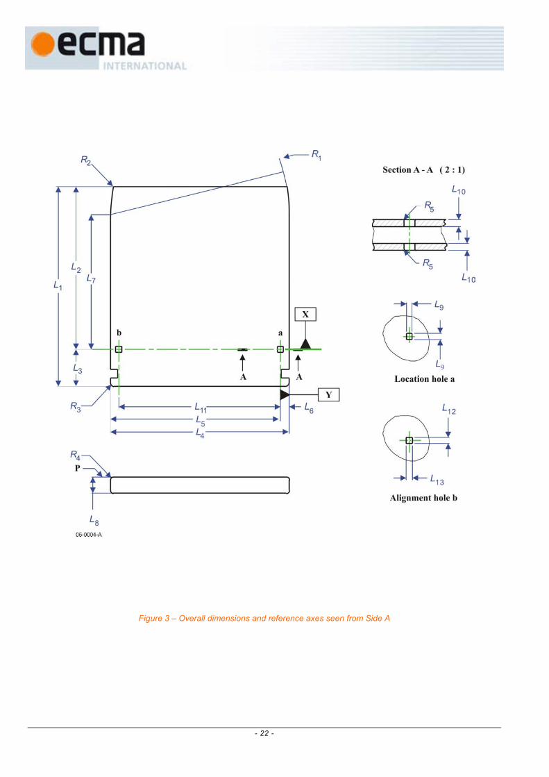
Figure 3 shows the envelope of the case with respect to a location hole at the intersection of the X and Y axes of Case Reference Plane P.
Figure 4 shows the surfaces S1, S2, S3 and S4 that establish the Case Reference Plane P located on side A.
Figure 4a shows the details of surface S3.
Figure 5 shows the details of the insertion slots and detents.
Figure 6 shows the gripper slots, used for automatic handling.
Figure 7 shows the write-inhibit hole.
Figure 8 shows the media identification sensor areas.
Figure 9 shows the head and motor windows.
Figure 10 shows the shutter opening features.
Figure 10a shows the locked/unlocked shutter levers configurations.
Figure 10b shows the shutter slider.
Figures 11a and 11b show the user label areas.
10.4 Dimensions of the case
10.4.1 Overall dimensions
The total length of the case (see Figure 3) shall be
L1 = 153,0 mm ± 0,4 mm
The distance from the top of the case to the reference axis X shall be
L2 = 127,0 mm ± 0,3 mm

- 14 -
The distance from the bottom of the case to the reference axis X shall be
L3 = 26,0 mm ± 0,3 mm
The total width of the case shall be
+ 0,0 mm L4 = 135,0 mm - 0,6 mm
The distance from the left-hand side of the case to the reference axis Y shall be
+ 0,0 mm L5 = 128,5 mm - 0,5 mm
The distance from the right-hand side of the case to the reference axis Y shall be
L6 = 6,5 mm ± 0,2 mm
The width shall be reduced on the top by the radius
R1 = L4
originating from a point defined by L5 and
L7 = 101,0 mm ± 0,3 mm
The two corners of the top shall be rounded with a radius
R2 = 1,0 mm ± 0,5 mm
and the two corners at the bottom with a radius
R3 = 3,0 mm ± 0,5 mm
The thickness of the case shall be
L8 = 11,00 mm ± 0,30 mm
The eight long edges of the case shall be rounded with a radius
R4 = 1,0 mm max.
10.4.2 Location hole
The centre of the location hole (see Figure 3) shall coincide with the intersection of the reference axes X and Y. It shall have a square form with a side length of
+ 0,00 mm L9 = 4,10 mm - 0,06 mm
held to a depth of
L10 = 2,4 mm ± 0,2 mm
The lead-in edges shall be rounded with a radius
R5 = 0,5 mm max.
10.4.3 Alignment hole
The centre of the alignment hole (see Figure 3) shall lie on reference axis X at a distance of
L11 = 122,0 mm ± 0,2 mm
from the reference axis Y.
The dimensions of the hole shall be
+ 0,00 mm L12 = 4,10 mm - 0,06 mm
and

- 15 -
+ 0,2 mm L13 = 5,0 mm - 0,0 mm
held to a depth of L10.
The lead-in edges shall be rounded with radius R5.
10.4.4 Surfaces on Case Reference Plane P
The Case Reference Plane P (see Figure 4) located on Side A of the case shall contain four surfaces (S1, S2, S3 and S4) on that side of the case, specified as follows:
- Two circular surfaces S1 and S2:
Surface S1 shall be a circular area centred on the square location hole and have a diameter of
D1 = 9,0 mm min.
Surface S2 shall be a circular area centred on the rectangular alignment hole and have a diameter of
D2 = 9,0 mm min.
- Two elongated surfaces S3 and S4 that follow the contour of the case:
Surfaces S3 and S4 are shaped symmetrically on the two top sides of the case.
Surface S3 (see also Figure 4a) on the right hand side shall extend from a height defined by distance L7 from the reference axis X to
L14 = 26,0 mm ± 0,3 mm
with a width of
L15 =1,35 mm ± 0,2 mm
and a right hand side boundary with radius
R6 = 132,65 mm
The top surface of the case shall not be higher than the Reference Plane on a width
L16 = 4,15 mm min.
located at the left hand boundary of S3.
10.4.5 Insertion slots and detent features
The case shall have two insertion slots with embedded detent features (see Figure 5). These slots shall be symmetrical relatively to the two sides of the case.
The slots shall have a length of
L17 = 44,0 mm ± 0,3 mm
a width of
+ 0,3 mm
L18 = 6,0 mm - 0,0 mm
and a depth of
L19 = 3,0 mm ± 0,1 mm
located
L20 = 2,5 mm ± 0,2 mm
from Case Reference Plane P.

- 16 -
The slots shall have a lead-in chamfer given by
L21 = 0,5 mm max.
L22 = 5,0 mm max.
The detent notch shall be a semi-circle of radius
R7 = 3,0 mm ± 0,2 mm
with the origin given by
L23 = 13,0 mm ± 0,3 mm
L24 = 2,0 mm ± 0,1 mm
L25 = 114,0 mm ± 0,3 mm
The dimensions L2, L23, and L25 are interrelated; their values shall be such so that they are all three within specification.
10.4.6 Gripper slots
The case shall have two symmetrical gripper slots (see Figure 6) with a depth of
L26 = 5,0 mm ± 0,3 mm
from the edge of the case and a width of
L27 = 6,0 mm ± 0,3 mm
The upper edge of a slot shall be
L28 = 12,0 mm ± 0,3 mm
above the bottom of the case.
10.4.7 Write-inhibit hole
The case shall have a write-inhibit hole (see Figure 7). The case shall include a device for opening and closing this hole.
When writing on the disk is not allowed, the write-inhibit hole shall be open all through the case. It shall have a diameter
D3 = 4,0 mm min.
Its centre shall be specified by
L29 = 8,0 mm ± 0,2 mm
L30 = 111,0 mm ± 0,3 mm
on Side A of the case.
When writing is allowed on the disk, the write-inhibit hole shall be closed, at a depth of typically L10, i.e. the wall thickness of the case. In this state, the opposite side of the hole, at Side B of the case, shall be closed and not recessed from the external surface of this side by more than
L31 = 0,4 mm max.
10.4.8 Media identif ication sensor areas
Media identifications sensor holes are considered to be used for identification of future other holographic cartridges. The cartridge specified in this Ecma Standard is considered to correspond to a closed state of these holes.
Identification of the cartridge of this Ecma Standard shall be done by sensing that the external surface of Side A of case is not deviating from Case Reference Plane P by more than 0,3 mm within the four identification areas (see Figure 8) having a diameter
+ 0,3 mm
D4 = 4,0 mm - 0,0 mm

- 17 -
and centres specified by
L32 = 19,5 mm ± 0,2 mm and L30
L33 = 105,0 mm ± 0,3 mm
L34 = 17,0 mm ± 0,2 mm
L35 = 11,0 mm ± 0,2 mm.
10.4.9 Head and motor windows
The case shall have a window on each side to allow the spindle of the drive to clamp the disk by its centre hole and to allow the head to access the disk (see Figure 9). The dimensions are referenced to a centreline, located at a distance of
L36 = 61,0 mm ± 0,2 mm
to the left of reference axis Y.
The width of the head access shall be defined by
L37 = 16,0 mm min.
L38 = 16,0 mm min.
and its height shall extend to
L39 = 113,2 mm min.
The two inside corners shall be rounded with a radius of
R8 = 3,0 mm max.
The motor spindle access shall have a diameter of
D5 = 32,0 mm min.
and its centre shall be defined by L36 and
L40 = 43,0 mm ± 0,2 mm
10.4.10 Shutter
The case shall have one spring-loaded, unidirectional shutter (see Figure 10), designed to completely cover the head and motor windows when closed. In the closed position the shutter shall be locked and the case shall have the light-proof characteristics of 10.6. +1,4 mm
A shutter movement of 38,7 mm shall ensure that the head and motor windows are -0,7 mm
opened to the minimum size specified in 10.4.9.
When unlocked, the shutter shall be free to slide in a recessed area of the case in such a way as to ensure that the overall thickness of the case and shutter shall not exceed L8.
The top surface of the shutter shall not be over the top edge of the case.
10.4.11 Shutter unlocking levers
Unlocking of the shutter shall be only obtained by a combined action on two spring-loaded levers configured as shown on Figures 10 and 10a.The levers shall be designed to be operated by a mechanism of the drive. The first lever shall be displaced by a defined distance (L46) to unlock the second lever, which shall be then displaced by another defined distance (L57) to unlock the shutter, which can then be pushed open.
The locked and unlocked configurations of the levers shall be as shown on Figure 10a.
The first lever shall be located on the right hand edge of Side A of the case.
When the shutter is locked in its closed position, the distances from the extremity of the first lever to references axes X and Y shall be
L41 = 103,6mm ± 0,3 mm

- 18 -
L42 = 6,0 mm ± 0,2 mm.
The height of the first lever shall be
L43 = 5,6mm ± 0,2 mm.
Its centre shall be
L44 = 5,5 mm± 0,2 mm
from the Case Reference Plane P of the case, and its width shall be
L45 = 4,0 mm ± 0,2 mm
The first lever displacement to unlock the second lever shall be
+1,2 mm
L46 = 2,0 mm
-0,5 mm
A rectangular sub-slot shall be located in the insertion slot on each side of the lever (see Figure 10a)
The sub-slot shall have a length of
L47 = 38,0 mm ± 0,3 mm
with a width of
L48 = 2,80 mm ± 0,15 mm
A symmetrical sub-slot shall be located in the left-hand side insertion slot.
The distance from the bottom of the right-hand side sub-slot to reference axis Y shall be
+ 0 mm
L49 = 2,8 mm - 0,2 mm
and the distance from the bottom of the left-hand side sub-slot to the reference axis Y shall be
+ 0 mm
L50 = 124,8 mm - 0,4 mm
The second lever shall be located on side A of the case.
This lever shall be moved by its rectangular hole.
The distances from the centre of the rectangular hole to the reference axes X and Y shall be
L51 = 117,7 mm ± 0,3 mm
L52 = 11,3 mm ± 0,3 mm
The length of the rectangular hole shall be
L53 = 4,2mm ± 0,2 mm
The width of the rectangular hole shall be
L54 = 4,1mm ± 0,2 mm
The distance from the top of the rectangular hole to the Case Reference Plane P shall be
L55 = 2,5 mm± 0,2 mm
The thickness of the second lever shall be
L56 = 6,0 mm± 0,2 mm
The second lever displacement to unlock the shutter shall be
+1,3 mm
L57 = 2,2mm -0,5 mm

- 19 -
10.4.12 Slider for shutter opener
The shutter shall have one slider (see Figures 10 and 10b) that can be operated by the shutter opener of the drive to open the shutter, after unlocking by the two levers. The slider shall be dimensioned as follows:
When the shutter is closed, the right-hand of projection of the slider used to push the shutter open shall be located at a distance of
L58 = 3,5 mm ± 0,3 mm
from reference axis Y.
The width of the projection of the slider shall be
L59 = 2,0 mm ± 0,2 mm
The height of the projection of the slider shall be
L60 = 3,2 mm ± 0,2 mm
The centre of the projection of the slider from the Case Reference Plane P of the case shall be
L61 = 5,5 mm ± 0,2 mm
The length of the projection of the slider shall be
L62 = 3,5 mm max.
The top of the projection of the slider shall be at a distance L2 of the reference axis X.
10.4.13 Feature to prevent insertion into UDO, MO and WO drives
The top edge side of the shutter shall have no slot (see Figures 2 and 10) so as to prevent from insertion into UDO, MO, WO drives using cartridges conforming to Standards ECMA-350, ECMA-322, ECMA-280, ECMA-238, ECMA-195, ECMA-184, ECMA-183 and ECMA-153.
10.4.14 User label areas
The case shall have the following minimum areas for user labels (see Figures 11a and 11b):
on Sides A and B: 25 mm x 79 mm
on the bottom side: 7,0 mm x 115,0 mm
These areas shall be recessed by 0,2 mm min. Their positions are specified by the following dimensions and relations between dimensions.
L63 = 14,5 mm min.
L64 – L63 = 79 mm min.
L66 – L65 = 25 mm min.
L4 – L67 – L68 = 115,0 mm min.
L8 – L69 – L70 = 7,0 mm min.
10.5 Mechanical characteristics
All requirements of this clause shall be met in the operating environment.
10.5.1 Materials
The case shall be constructed from any suitable materials such that it meets the requirements of this Ecma Standard.
10.5.2 Mass
The mass of the case without the holographic disk shall not exceed 200 g.
10.5.3 Edge distort ion
The cartridge shall meet the requirement of the edge distortion test defined in Annex A.

- 20 -
10.5.4 Compliance
The cartridge shall meet the requirement of the compliance (flexibility) test defined in Annex B. The requirement guarantees that a cartridge can be constrained in the proper plane of operation within the drive.
10.5.5 Shutter opening force
The spring force on the shutter shall be such that the force required to open the shutter does not exceed 2 N. It shall be sufficiently strong to close a free-sliding shutter, irrespective of the orientation of the case.
10.5.6 Levers unlocking forces
The spring forces on the levers shall be sufficiently strong to maintain the shutter locked in any orientations of the case, and such that the force exerted on each lever to unlock the shutter does not exceed 1N.
10.6 Light-proof characteristics
The Holographic Disk Cartridge with closed and locked shutter shall withstand the light proof test as defined in Annex C.
10.7 Drop test
The Holographic Disk Cartridge shall withstand dropping on each surface and on each corner from a height of 0,75 m onto a concrete floor covered with a vinyl layer 2 mm thick. The cartridge shall withstand all such impacts without any functional failure.
The write-inhibit switch shall not move to change the state (open or closed) of the write-inhibit hole during the drop test.
10.8 Electro-static discharge test
The Holographic Disk Cartridge shall meet the electro-static discharge requirements specified in Annex D.

- 21 -
Figure 2 – Case seen from Side A
- 22 -
Figure 3 – Overall dimensions and reference axes seen from Side A

- 23 -
Figure 4 – Surfaces S1, S2, S3 and S4 of the Case Reference Plane P on Side A

- 24 -
Figure 4a – Details of surface S3

- 25 -
Figure 5 – Insertion slots and detents

- 26 -
Figure 6 – Gripper slots

- 27 -
Figure 7 – Write-inhibit hole seen from Side A

- 28 -
Figure 8 – Media identification sensor areas on Side A

- 29 -
Figure 9 – Head and motor windows on Side A

- 30 -
Figure 10 – Shutter opening features seen from Side A

- 31 -
Shutter closed and locked Shutter closed and unlocked
Figure 10a – Locked/unlocked shutter levers configurations

- 32 -
Figure 10b – Shutter slider seen from Side A

- 33 -
Figure 11a – User label area on Side A
Figure11b – User label area on bottom surface
- 34 -
11 Dimensional, mechanical, and physical characteristics of the
disk
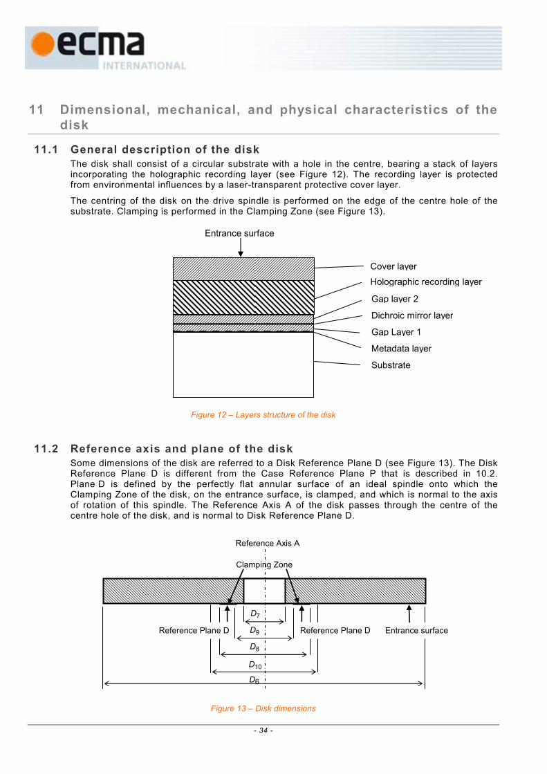
11.1 General description of the disk
The disk shall consist of a circular substrate with a hole in the centre, bearing a stack of layers incorporating the holographic recording layer (see Figure 12). The recording layer is protected from environmental influences by a laser-transparent protective cover layer.
The centring of the disk on the drive spindle is performed on the edge of the centre hole of the substrate. Clamping is performed in the Clamping Zone (see Figure 13).
Figure 12 – Layers structure of the disk
11.2 Reference axis and plane of the disk
Some dimensions of the disk are referred to a Disk Reference Plane D (see Figure 13). The Disk Reference Plane D is different from the Case Reference Plane P that is described in 10.2. Plane D is defined by the perfectly flat annular surface of an ideal spindle onto which the Clamping Zone of the disk, on the entrance surface, is clamped, and which is normal to the axis of rotation of this spindle. The Reference Axis A of the disk passes through the centre of the centre hole of the disk, and is normal to Disk Reference Plane D.
Figure 13 – Disk dimensions
Cover layer
Holographic recording layer
Dichroic
Gap layer 2
Metadat
Substra
Entrance
Gap Lay
Referenc
Clamping
Reference Plane D
D7
D9
D8
D10
D6
Reference Plane D
Entrance surfaceZone
e Axis A
er 1
surface
te
a layer
mirror layer

- 35 -
11.3 Dimensions of the disk
The dimensions of the disk shall be measured in the operating environment. The outer diameter of the disk shall be (see Figure 13)
D6 = 120 mm ± 0,30 mm
The centre hole shall have a diameter
+ 0,15 mm
D7 = 15,00 mm - 0,00 mm
There shall be no burr on the edges of the centre hole.
The edge of the centre hole shall be rounded off or chamfered. The rounding radius shall be 0,1 mm max. The chamfer shall extend over a height of 0,1 mm max.
The total thickness of the disk shall be 2,3 mm min. and 2,6 mm max.
11.4 Clamping Zone
The Clamping Zone is the area on the entrance surface of the disk where the clamping mechanism of the drive grips the disk and is defined by D8 and D9 (see Figure 13).
The clearance zone extending from the outer diameter of the Clamping Zone (D8) to the inner diameter of the reflective zone (D10) (see Clause 17) shall be excluded from the total thickness requirement; however there shall be no projection from the Disk Reference Plane D in the direction of the optical system of more than 0,2 mm in this zone.
The outer diameter of the Clamping Zone shall be
D8 = 28 mm min.
The inner diameter of the Clamping zone shall be
D9 = 22 mm max.
11.5 Mechanical characteristics
All requirements in this clause shall be met in the operating environment.
11.5.1 Material
The disk shall be made from any suitable materials such that it meets the requirements of this Ecma Standard.
11.5.2 Mass
The mass of the disk shall not exceed 80 g.
11.5.3 Moment of inert ia
The moment of inertia of the disk relative to axis A shall not exceed 0,160 g⋅m2.
11.5.4 Imbalance
The imbalance of the disk relative to axis A shall not exceed 0,040 g⋅m.
11.5.5 Axial deflection
The axial deflection of the disk is measured as the axial deviation of the tracking/addressing layer. Thus it comprises the tolerances on the thicknesses of the crossed layers, on their indexes of refraction, and the deviation of the entrance surface from the Disk Reference Plane D.
The deviation of any point of the tracking/addressing layer from its nominal position, in a direction normal to the Disk Reference Plane D, shall not exceed 0,3 mm in the Formatted Zone for rotational frequencies of the disk as specified in 9.5. The deviation shall be measured by the optical system defined in 9.1.

- 36 -
11.5.6 Axial acceleration
The maximum allowed axial error emax (see Annex P) shall not exceed 0,23 µm, measured using the Reference Servo for axial tracking of the tracking/addressing layer. The rotational frequency of the disk shall be as specified in 9.5. The stationary part of the motor is assumed to be motionless (no external disturbances). The measurement shall be made using a servo with the transfer function
0
00
3ω
i+1
ω
3i+1
i
ω
3
1)(i
2
s ω
ω
ωωH ××=
where ω = 2πf, ω0/2π = 450 Hz, i = -1
or any other servo with 1 + H within the 20 % of 1 + Hs in the bandwidth of 5 Hz to 1 kHz. Thus, the disk shall not require an acceleration of more than 0,38 m/s
2 at low frequencies from
the servo motor of the Reference Servo.
11.5.7 Radial runout
The radial runout of the tracks in the tracking/addressing layer is measured as seen by the optical head of the Reference Drive. Thus it includes the distance between the axis of rotation of the spindle and reference axis A, the tolerances on the dimensions between axis A and the location of the track, and effects of non-uniformities in the index of refraction of the stack of layers.
The radial runout is the difference between the maximum and the minimum distance of any track from the axis of rotation, measured along a fixed radial line over one track. The radial runout shall not exceed 70 µm as measured by the optical system under conditions of a disk mounted on a perfect sized test fixture shaft, for rotational frequencies of the disk as specified in 9.5.
11.5.8 Radial acceleration
The maximum allowed radial error emax (see Annex P) shall not exceed 0,022 µm, measured using the Reference Servo for radial tracking of the tracks. The rotational frequency of the disk shall be as specified in 9.5. The stationary part of the motor is assumed to be motionless (no external disturbances).
The measurement shall be made using a servo with the transfer function
0
00
3ω
i+1
ω
3i+1
i
ω
3
1)(i
2
s ω
ω
ωωH ××=
where ω = 2πf, ω0/2π = 650 Hz, i = -1
or any other servo with 1 + H within the 20 % of 1 + Hs in the bandwidth of 5 Hz to 1,0 kHz. Thus, the disk shall not require an acceleration of more than 0,08 m/s
2 at low
frequencies from the servo motor of the Reference Servo.
11.5.9 Tilt
The tilt angle, defined as the angle that the normal to the entrance surface, averaged over a circular area of 1 mm diameter, makes with the normal to the Disk Reference Plane D, shall not exceed 0,80° in the radial direction and 0,30° in the tangential direction, in the Formatted Zone.

- 37 -
11.6 Optical characteristics
11.6.1 Substrate
The substrate has no optical requirement.
11.6.2 Metadata layer
The Metadata layer shall be constituted of a reflective layer bearing data pits.
11.6.3 Gap layer 1
The thickness and index of refraction of Gap layer 1 at wavelength λT shall be such than within the Formatted Zone, the combined stack of layers specifications of 11.6.8 and 11.6.9 shall be met.
11.6.4 Dichroic mirror layer
The reflectance of the dichroic mirror layer within the Formatted Zone, measured according to Annex E, shall be at least 80% at wavelength λR specified in 9.3 and 9.4.
11.6.5 Gap layer 2
The thickness, index of refraction and birefringence of Gap layer 2 at wavelength λT and λR shall be such than within the Formatted Zone, the combined stack of layers specifications of 11.6.8 and 11.6.9 shall be met.
11.6.6 Holographic recording layer
The holographic recording layer shall be used to record the Data Page holograms.
The recording layer characteristics are specified in Section 5.
Its thickness, index of refraction and birefringence shall be such than within the Formatted Zone, the combined stack of layers specifications of 11.6.8 and 11.6.9 shall be met.
11.6.7 Cover layer
The cover layer shall be used to protect the other layers.
Its thickness and index of refraction shall be such than within the Formatted Zone, the combined stack of layers specifications of 11.6.8 and 11.6.9 shall be met.
11.6.8 Thicknesses of the stack of layers
The thickness within the Formatted Zone of the stack "cover layer + holographic recording layer + Gap layer 2 + Dichroic mirror layer + Gap layer 1" shall be determined versus the average index of refraction Nav at wavelength λT, as specified in Figure 14.
The thickness within the Formatted Zone of the stack "cover layer + holographic recording layer + Gap layer 2" shall be determined versus the average index of refraction Nav at wavelength λR, as specified in Figure 15.
The average index Nav of the stack of layers with individual thicknesses and indexes Ti and Ni shall be calculated as Nav = ∑ Ni.Ti / ∑Ti , with 1,45 ≤ Ni ≤ 1,65

(3) HVD - between surface and Reflective layer
1.10
1.14
1.18
1.22
1.26
1.30
1.34
1.38
1.4 1.45 1.5 1.55 1.6 1.65 1.7
Index of re
Figure 14 – Thickness of stack of layer between entrance surface and reflective pit Layer
(2) HVD - between surface and Dichroic mirror layer
1.10
1.14
1.18
1.22
1.26
1.30
1.34
1.38
1.4 1.45
Figure 15 – Thickness of stack of
Thickness of the stack of layers between entrance surface and reflective pit layer
Thickness of the stack of layers between entrance surface and dichroic mirror layer
Avera
Average index of refra
mm
mm
- 38 -
1.5 1.5
Index of
layers between e
ge index of refra
fractionction at λT
5 1.6 1.65 1.7
refractionction at λR
ntrance surface and dichroic mirror layer

- 39 -
11.6.9 Birefringence of the stack of layers
The birefringence of the layers within the Formatted Zone, measured according to Annex F, shall be less than:
- 100 nm for the stack "cover layer + holographic recording layer + Gap layer 2 + Dichroic mirror layer + Gap layer 1" at wavelength λT,
- 100 nm for the stack "cover layer + holographic recording layer + Gap layer 2" at wavelength λR.
12 Interface between cartridge and drive
12.1 Clamping method
When the cartridge is inserted into the drive, the shutter of the case is opened and the drive spindle engages the disk. The disk is held against the spindle by an axial clamping force. The radial positioning of the disk is provided by the centring of the axis of the spindle in the centre hole of the disk. A turntable of the spindle shall support the disk in its Clamping Zone, determining the axial position of the disk in the case.
12.2 Tapered cone for disk clamping
The device used for centring the disk for test measurements shall be a cone as defined in Annex G.
12.3 Clamping force
The clamping force exerted by the spindle shall be less than 2,0 N ± 0,2 N.
12.4 Capture cylinder
The capture cylinder (see Figure 16) is defined as the volume in which the spindle can expect the centre of the external side of the hole of the disk to be, just prior to capture. The size of the cylinder limits the allowable play of the disk inside its cavity in the case. This cylinder is referred to perfectly located and perfectly sized alignment and location pins in the drive, and includes tolerances of dimensions of the case and the disk between the pins mentioned and the said centre of the hole of the disk. The bottom of the cylinder is parallel to the Case Reference Plane P, and shall be located at a distance of
L71 = 2,45 mm min.
above the Case Reference Plane P of the case. The top of the cylinder shall be located at a distance of
L72 = 6,45 mm max.
above the Case Reference Plane P. The diameter of the cylinder shall be
D11 = 2,8 mm max.
Its centre shall be defined by the nominal values of L36 and L40 (see 9.4.9).
12.5 Disk position in operating condition
When the disk is in the operating condition within the drive (see Figure 16), the disk shall not contact the case when the axis of rotation is within a circle of diameter
D12 = 0,2 mm max.
and a centre given by the nominal values of L36 and L40 (see 9.4.9),
and the position of the pit layer shall be
L73 = 4,8 mm ± 0,15 mm
above the Case Reference Plane P of the case.

- 40 -
Figure 16 – Capture cylinder

- 41 -
Section 3 - Format of information
13 General description
This section specifies:
- the format of the tracking/addressing information and manufacture specific disk information contained in the pit layer,
- the format of the data information stored in form of holograms in the recording layer.
14 Tracking and addressing information format / Specific Disk
Information format
The tracking/addressing information and manufacture Specific Disk Information shall be disposed along circular concentric tracks on the internal surface of the substrate and shall consist of successive depressions as seen from the entrance surface of the disk, called pits, in the otherwise flat reflective layer. The information shall be represented by variations of pit length and distance between pits.
There shall be 20 172 pit tracks. + 0,2 mm
The first pit track at the inside of the disk shall be located at radius 22,4 mm - 0,0 mm
14.1 Pit track pitch
The pit track pitch shall be 1,6 µm ± 0,1 µm.
The pit track pitch averaged over the Formatted Zone shall be 1,6 µm ± 0,01 µm.
14.2 Pit track format
The pit track format is described hereafter in term of Channel bits.
Each track shall contain 302 400 Channel bits. At the nominal test rotation speed of 300 rpm the nominal channel bit time period T shall be 661 ns.
The physical Channel bit length shall consequently vary with the track radius.
14.2.1 Sector
The track (one revolution) shall be divided in 120 Sectors numbered from 0 to 119.
The Sector layout shall be as shown in Figure 17.
Header Sync Tracking data Land
Number of Channel bits per field
184 40 2 288 8
Sector total Channel bits = 2 520
Figure 17 – Sector format

- 42 -
14.2.2 Header
The header layout shall be as shown in Figure 18.
Address Mark Address data ECC Reserved field
Number of Channel bits per field
48 64 32 40
Header total Channel bits = 184
Figure 18 – Header format
14.2.2.1 Address Mark
The Address Mark shall consist of a pattern that does not occur elsewhere in the Sector. It shall have length of 48 Channel bits with the following pattern:
4T 4T 14T 4T 4T 14T 4T
land
pit
Total: 48 Channel bits
Figure 19 – Address Mark
14.2.2.2 Address data
The Address data format shall be as shown in Figure 20.
Control data Track number H Track number L Sector number
Number of Channel bits per field
16 16 16 16
Address total Channel bits = 64
Figure 20 – Address data
The Control data bits shall be generated as shown in Figure 20.a.
The track address of the first track at inner radius shall be –1 280.
The track addresses of tracks located at radii larger than Track –1 280 shall be increased by 1 for each track.

- 43 -
Figure 20.a – Generation of Control data
The higher 16 bits, Track Number H, of Track Number data bits shall be generated as shown in Figure 20.b.
Figure 20.b – Generation of higher digits of Track Number data

- 44 -
The lower 16 bits, Track Number L, of Track Number data bits shall be generated as shown in Figure 20.c.
Figure 20.c – Generation of lower digits of Track Number data
The Sector Number data bits shall be generated as shown in Figure 20.d.
Figure 20.d – Generation of Sector Number data

- 45 -
14.2.2.3 ECC
The ECC data format shall be as shown in Figure 21.
Control data ECC Track number H ECC Track number L ECC Sector number ECC
Number of Channel bits per field
8 8 8 8
ECC total Channel bits = 32
Figure 21 – ECC data
The higher digits of ECC data bits shall be generated as shown in Figure 21.a.
Figure 21.a – Generation of higher digits of ECC data
The lower digits of ECC data bits shall be generated as shown in Figure 21.b.

- 46 -
Figure 21.b – Generation of lower digits of ECC data
14.2.2.4 Reserved f ield
The reserved field shall be a blank space of 40 Channel bits length.
The reserved field shall be ignored in interchange.
14.2.3 Sync
This field shall have a 40 channel bits length and shall consist of a 3T/16T/16T/5T land/pit pattern, as shown on Figure 22.
3T 16T 16T 5T
land
pit
Total: 40 Channel bits
Figure 22 – Sync field pattern
14.2.4 Tracking data
This field shall have a 2 288 channel bits length and shall consist of a 4T land / 4T pit pattern, starting with a 4T land as shown on Figure 23.

4T 4T 4T 4T 4T 4T 4T 4T
land
pit
Total: 2 288 Channel bits
Figure 23 – Tracking data pattern
14.2.5 Land
Each Sector shall finish with a land field with a length of 8 Channel bits.
14.3 Specific Disk Information (SDI)
The Specific Disk Information (SDI) shall be recorded in the tracking data area of the Lead-in tracks of the pit layer, as specified in Annex H.
14.3.1 SDI bytes encoding
The encoding of the SDI bytes shall be processed as shown on Figure 24.
The encoded bits shall be represented by pits and lands of the pit tracks.
Figure 24 – SDI bytes encoding
14.4 Channel bits radial alignment
The misalignment δ of the Channel bits of adjacent tracks, as defined on Figure 25, shall be less than ± 50 nm.
(n+1)th track
nth track
δ
- 47 -
Figure 25 – Channel bit alignment

- 48 -
15 Data information format
The data information shall be stored in the form of holograms in the volume of the recording layer. Each hologram shall contain a Data Page of information.
15.1 Data Page holograms layout in the recording layer
All hologram layout format characteristics shall be specified in reference to the pit layer, as access to the information in the holographic recording layer is defined through the tracking/addressing features of the pit layer. The hologram track address shall be in particular designated by the corresponding pit track address.
15.1.1 Radial Data Page hologram pitch
The radial Data Page hologram pitch, the hologram track pitch, shall correspond to 4 pit track pitches.
15.1.2 Data Page hologram layout within tracks
The holograms shall be recorded in each track through n successive disk rotations, as shown on Figure 26, where numbers correspond to the sequential order of recorded holograms. The series of n holograms recorded that way shall constitute a "Peapod".
Once all 840 Peapods of a track have been recorded, the recording shall be continued the same way on the following track.
Figure 26 – Data Page holograms layout in a hologram track
15.1.3 Zones / Tangential Data Page hologram pitch / Number of Data Page holograms
per Peapod
The holograms shall be exclusively recorded in the tracking data area of the track. Within this area the tangential Data Page hologram pitch shall be the same in Zones defined in Table 1. This pitch shall vary from 12 to 4 Channel bit periods depending on the Zone.
The centre of holograms shall coincide with passages to Zero of the Channel bit period signal. The centre of the first hologram in a track shall coincide with the third transition of the pit signal in the tracking data area (see Figure 27).
The number of Data Page holograms per Peapod shall vary from Zone to Zone, as shown in Table 1.
At each rotation a hologram shall be recorded in each Peapod until all available space is filled. The number of holograms recorded in the last (7
th) Peapod of each Sector (see Table 1) shall
be reduced due to the smaller tracking data area space available for this Peapod at the end of each Sector.

- 49 -
Table 1 – Zones with dif ferent tangential Data Page hologram pitches
Zone Start pit track number
End pit track number
Number of pit tracks
Start address
End address
Number of hologram
tracks
Tangential hologram pitch
(Number of Channel bit
periods)
Holograms per Peapod
Peapods* 0,1, … 5
7, 8, … 12 ………….
833, 834,… 838
Peapods** 6, 13,
…….. 839
0 - 1 280 - 1 1 280 (FB00) (FFFF) 47*** 12 30 10
1 0 1 279 1 280 (0000) (04FF) 320 8 45 15
2 1 280 2 559 1 280 (0500) (09FF) 320 8 45 15
3 2 560 3 839 1 280 (0A00) (0EFF) 320 8 45 15
4 3 840 5 119 1 280 (0F00) (13FF) 320 8 45 15
5 5 120 6 399 1 280 (1400) (18FF) 320 8 45 15
6 6 400 7 679 1 280 (1900 (1DFF) 320 8 45 15
7 7 680 8 959 1 280 (1E00) (22FF) 320 8 45 15
8 8 960 10 239 1 280 (2300) (27FF) 320 8 45 15
9 10 240 11 519 1 280 (2800) (2CFF) 320 8 45 15
10 11 520 12 799 1 280 (2D00 (31FF) 320 8 45 15
11 12 800 14 079 1 280 (3200) (36FF) 320 8 45 15
12 14 080 15 359 1 280 (3700) (3BFF) 320 8 45 15
13 15 360 16 639 1 280 (3C00) (40FF) 320 4 90 30
14 16 640 17 919 1 280 (4100) (45FF) 320 4 90 30
15 17 920 18 879 960 (4600) (49BF) 240 4 90 30
16 18 880 18 891 12 (49C0) (49CB) 3 4 90 30
NOTES: * First six Peapods of Sectors.
** Last seventh Peapods of Sectors
*** Only a part of Zone 0 is used to store holograms (see 16.2.1).
Figure 27 – Position of the first Data Page hologram in a track

- 50 -
15.2 Data Page encoding
15.2.1 User data
The user data bytes shall be processed as shown on Figure 28 to generate the content of the Data Page of the hologram.
Each 192 512 user data bytes shift shall be formatted in 188 packets of 1 024 bytes (see Figure 29).
These bytes shall be processed by addition of Header, Footer, Inter-Page ECC, Page number, Intra-Page ECC, scrambling to generate the content of the Data Page holograms.
Figure 28 – Data Page encoding
Figure 29 – Addition of Page number, Header and Footer
15.2.2 Header
28 bytes Header shall be added to each 1 024 user bytes packet (See Figures 28 and 29).
These bytes shall be set to ZERO. They shall be ignored in interchange.
15.2.3 Footer
16 bytes Footer shall be added to each 1 024 user bytes packet (See Figures 28 and 29).
These bytes shall be set to ZERO. They shall be ignored in interchange.
15.2.4 ECC
Error Correction Code (ECC) bytes are used by the error detection and correction system to rectify erroneous data in Data Pages.
User data Addition of Header and Footer
Addition of Page number
Scrambling Data Page content
Addition of Intra-Page ECC
Addition of Inter-Page ECC

- 51 -
15.2.4.1 Inter-Page ECC
The 1 068 bytes of 188 user data packets constituted of Header + User data + Footer shall be processed by a Reed-Solomon code, as specified in Annex I1, to generate 20 packets of 1 068 Inter-Page ECC bytes, as shown on Figure 30.
15.2.4.2 Page number
4 bytes sequential Page numbers shall be added to each of the preceding 188+20 = 208 packets. Page number 0 shall be given to the first Page at inner diameter. Page numbers shall be incremented by one for each following Page.
15.2.4.3 Intra-Page ECC
The 1 072 bytes of each of the here above 208 packets shall be processed as specified in Annex I2 to generate 560 Intra-Page ECC bytes that shall be added to each of these 1 072 bytes to constitute the 1 632-bytes content of the Data Page, as shown on Figure 30.
Page number + Header + User data + Footer 0 1 072 bytes Intra-Page ECC 560 bytes
Page number + Header + User data + Footer 1 1 072 bytes Intra-Page ECC 560 bytes
…… : … … …… … …
Page number + Header + User data + Footer m 1 072 bytes Intra-Page ECC 560 bytes
…… : … … …… … …
Page number + Header + User data + Footer 187 1 072 bytes Intra-Page ECC 560 bytes
Page number + Inter-Page ECC 0 1 072 bytes Intra-Page ECC 560 bytes
…… : … … …… … …
Page number + Inter-Page ECC 19 1 072 bytes Intra-Page ECC 560 bytes
Data before 8 to 16 bits conversion
Page number 4 bytes Header + User data + Footer 0 1 068 bytes Page number + Header +User data + Footer 0 2 144 bytes Intra-Page ECC 560 bytes
Page number 4 bytes Header + User data + Footer 1 1 068 bytes Page number + Header + User data + Footer 1 2 144 bytes Intra-Page ECC 560 bytes
… … … …… : … … : : …… : … … : …… … …
… … … …… : … … : : …… : … … : …… … …
Page number 4 bytes Header + User data + Footer m 1 068 bytes 8 bits/16 bits Page number + Header + User data + Footer m 2 144 bytes Intra-Page ECC 560 bytes
… … … …… : … … : conversion : …… : … … : …… … …
… … … …… : … … : through : …… : … … : …… … …
Page number 4 bytes Header + User data + Footer 187 1 068 bytes the Page number + Header + User data + Footer 187 2 144 bytes Intra-Page ECC 560 bytes
look-up
table
Page number 4 bytes Inter-Page ECC 0 1 068 bytes Page number + Inter-Page ECC 0 2 144 bytes Intra-Page ECC 560 bytes
… … … …… : … … : : …… : … … : …… … …
Page number 4 bytes Inter-Page ECC 19 1 068 bytes Page number + Inter-Page ECC 19 2 144 bytes Intra-Page ECC 560 bytes
Figure 30 – Inter-Page and Intra-Page ECC codes
15.2.5 Scrambling
The 1 632-bytes Data Page content shall be scrambled by means of the circuit shown in Figure 31 which shall consist of a feedback bit shift register in which bits r7 (msb) to r0 (lsb) represent a scrambling byte at each 8-bit shift. The scrambling shall start at the beginning of each every 208 Pages, with pre-set values of positions r14 to r0 of the shift register as specified in Figure 31.
Figure 31 – Feedback shift register for generating the scrambling bytes

- 52 -
15.3 Digital to image conversion
15.3.1. 8 to 16 bits conversion
Each of the 1 632 bytes corresponding to the content of a page shall be transformed to 2x1 632 bytes by a 8 to 16 bits conversion using the look-up table shown on Figure 32.
This conversion shall be such that three 1's shall appear within each successive 16 bits.
Each 1 632 obtained bytes shall represent the hologram recorded content of a Data Page (see Figure 33).
Data (hex) 15 14 13 12 11 10 9 8 7 6 5 4 3 2 1 0 Digit
0 0 0 0 0 0 0 0 0 0 0 0 1 1 0 1 0
01 0 0 0 0 0 0 0 0 0 0 1 0 0 1 0 1
02 0 0 0 0 0 0 0 0 0 0 1 0 1 0 0 1
: : :
: : :
80 0 0 0 0 1 0 1 0 0 0 0 0 0 1 0 0
B m, n 81 0 0 0 0 1 0 1 0 0 0 0 0 1 0 0 0 BB m, n
8 bits, 1 byte 82 0 0 0 0 1 0 1 0 0 0 0 1 0 0 0 0 16 bits, 2 bytes: : :
: : :
FD 1 0 0 0 0 1 0 0 0 0 1 0 0 0 0 0
FE 1 0 0 0 0 1 0 0 1 0 0 0 0 0 0 0
FF 1 0 0 0 0 1 0 1 0 0 0 0 0 0 0 0
8 bits, 1 byte 16 bits, 2 bytes
Three "1"s for each 16-bits (2-bytes) data
Look-up table for 8 to 16 bits conversion
B 0, 0 B 1, 0 … B 1 071, 0 BB 0, 0 BB 1, 0 … BB 1 071, 0
B 0, 1 B 1, 1 … B 1 071, 1 BB 0, 1 BB 1, 1 … BB 1 071, 1
: : :
B 0, n B 1, n … B 1 071, n BB 0, n BB 1, n … BB 1 071, n
: : : : : :
B 0, 207 B 1, 207 … B 1 071, 207 BB 0, 207 BB 1, 207 … BB 1 071, 207
1 072 bytes 1 072 x 2 : 2144 bytes
Figure 32 – 8 to 16 bits conversion
Figure 33 – Data Page image generation
Data Page 0 1 632 bytes Page Data Page 1 1 632 bytes Coding
Data Page … … bytes : : Data Page … … bytes : : Data Page m 1 632 bytes 8 to 16 bits : Data Page … … bytes : conversion : Data Page … … bytes : : Data Page 187 1 632 bytes Digital : Data Page 188 1 632 bytes data : Data Page … … bytes : : Data Page 207 1 632 bytes pixel image

- 53 -
15.3.2 Symbol/Sub-Page
After the 8 to 16 bits conversion, each 16 bits shall be represented in the Data Page by a 4X4 On/Off-pixels Symbol, as illustrated on Figure 34, using the look-up table of Annex J. Bits to One shall correspond to On (illuminated) - pixels of the Data Page. Bits to Zero shall correspond to Off (non-illuminated) - pixels of the Data Page.
0 1 2 3
4 5 6 7
digits digits 8 9 10 11
7 6 5 4 3 2 1 0 15 14 13 12 11 10 9 8 7 6 5 4 3 2 1 0 12 13 14 15
0 0 0 0 0 0 0 0 0 0 0 0 0 0 0 0 0 0 0 1 1 0 1 0 �������������������� ������������: : :
: : :
0 0 0 0 1 0 0 1 0 0 0 0 0 0 0 0 1 0 0 1 0 1 0 0 �������������������� ������������: : :
: : :
1 1 1 1 1 1 1 1 1 0 0 0 0 1 0 1 0 0 0 0 0 0 0 0 �������������������� ������������8 bit 16 bit Symbol
Figure 34 – Data Page pixel symbols representation after 8 to 16 bits conversion
A Sub-Page Sync Mark constituted of 16 On-pixels shall be added to 32 Symbols to constitute the Sub-Page image that shall be organized as shown on Figure 35.
Figure 35 – Pixel Symbols organization of the content of a Sub-Page
See look
On-pixel
Off-pixel
-up table in Annex J

A Page Sync Mark constituted of 16 On-pixels shall be added to 51 Sub-Pages to generate the Data Page image that shall be organized as shown on Figure 36.
Fig
15.4 Data Page hologram
The Data Page image genrecording layer with the Ref
This pattern shall be consmodulator. The inner and obe 1 pixel.
Figure 37 – Refere
1 2 3
4 5 6 7 8 9
10 11 12 13 14 15 16 17
18 19 20 21 22 23 24 25
26 27 28 29 30 31 32 33
34 35 36 37 38 39 40 41
42 43 44 45 46 47
38 49 50 51
Page Sync -Page
1 Page = 1
Page Sync Mark + 51 Sub-Pages = 1 632 bytesMark = 16 centred On-pixels Sub
- 54 -
ure 36 – Sub-Page organization of a Page
- Reference Pattern
erated as specified in 15.3.2 shall be recorded as a hologram in the erence Pattern shown in Figure 37.
tituted of 120 radial lines of On-pixels generated by the spatial light uter diameters shall be 230 and 358 pixels. The width of the lines shall
nce Pattern used to record the hologram of the Data Page

- 55 -
16 Formatted Zone
16.1 General description of the Formatted Zone
The Formatted Zone contains all information on the disk relevant for data interchange. This information comprises tracking/addressing/SDI provisions, and possibly user written data. In this clause the term "data" is reserved for the content of the data field of a Data Page, which, in general, is transferred to the host.
Clause 16 defines the layout of the information. The characteristics of signals obtained from this information are specified in sections 4 and 6.
16.2 Content/usage of the Formatted Zone
The Formatted Zone shall be structured and used as shown in Table 2.
Table 2 – Content/usage of the Formatted Zone
Content /
usage
Zone
number(s)
Pit track
addresses
(Decimal)
Pit track
addresses
(Hexadecimal)
Number of
pit tracks
Number of
hologram
tracks
Lead-in Zone 0 -1 280 to -831 (FB00) to (FCC1) 450 ….
Buffer Zone 1 0 -830 to -511 (FCC2) to (FE01) 320 …
Test Zone 0 -510 to -321 (FE02) to (FEBF) 190 47
Buffer Zone 2 0 -320 to -1 (FEC0) to (FFFF) 320 ….
User data Zone
1 to 15 0 to 18 879 (0000) to (49BF) 18 880 4720
Lead-out Zone 16 18 880 to 18 8911
(49C0) to (49CB) 12 3
16.2.1 Zone 0 – Lead-in Zone / Buffer Zone 1 / Test Zone / Buffer Zone 2
The Zone 0 shall be divided in 4 Sub-Zones
16.2.1.1 Lead-in Zone
The Lead-in Zone shall be used for storing the SDI. The Lead-in Zone shall comprise 450 pit tracks.
16.2.1.2 Buffer Zone 1
The Buffer Zone 1 shall comprise 320 pit tracks.
16.2.1.3 Test Zone
The Test Zone shall be used for write/read tests. The Test Zone shall comprise 190 pit tracks corresponding to 47 hologram tracks.
16.2.1.4 Buffer Zone 2
The Buffer Zone 2 shall comprise 320 pit tracks.
16.2.2 Zones 1 to 15 - User data Zone
Zones 1 to 15 shall constitute the User data Zone used to record user data.
The User data Zone shall comprise 18 880 pit tracks corresponding to 4720 hologram tracks that may contain 191 520 000 holograms recording 173 104 615 user Data Pages.
The first user hologram on the disk shall be recorded centred on pit Track 0.

- 56 -
16.2.3 Zone 16 - Lead-out Zone
The Lead-out Zone shall be used to record finalizing data. The Lead-out Zone shall comprise 12 pit tracks corresponding to 3 hologram tracks.
17 Finalizing
Finalizing of the recorded disk shall be performed in recording the data specified in Annex K in a Data Page recorded repetitively in the 3 hologram tracks of the Lead-out Zone. After finalizing no further recording shall be permitted.
Section 4 - Characteristics of the tracking/addressing and SDI
information
18 Method of testing
The format of the pit tracking/addressing and SDI information on the disk is defined in Clause 14. Clause 19 specifies the requirements for the signals from the tracks, addresses and SDI, as obtained when using the Reference Drive specified in Clause 9.
18.1 Environment
All signals specified in Clause 19 shall be within their specified ranges with the cartridge in any environment in the range of allowed operating environments defined in 8.1.2.
18.2 Use of the Reference Drive
All signals specified in Clause 19 shall be measured in the indicated channel of the Reference Drive. The drive shall have the following characteristics for the purpose of these tests.
18.2.1 Optics and mechanics
The drive shall have a Tracking/Addressing Channel, with the implementation as given in 9.2.
The tracking/addressing beam shall have the properties defined in 9.2.1.
The disk shall rotate as specified in 9.5.5.
18.2.2 Tracking/addressing beam power
The tracking/addressing beam power shall be 0,5 mW ± 0,2 mW.
18.2.3 Tracking requirements
During the measurement of the signals, the focus of the beam shall follow the pit track with the requirements defined in Clause 9.5.1.
18.3 Definition of signals
Figure 38 shows the signals specified in Clause 19.
All signals are linearly related to currents I1 and I2 derived from the outputs of the split photodiode detector of the Reference Drive (see 9.1), and are therefore linearly related to the optical power falling on the detector.
The reading signal I provided by the Addressing Channel is the high bandwidth sum signal
I = I1 + I2
as processed by the band-pass filter described in Annex L.1.

- 57 -
Beam on track in the tracking data field
I1 + I2 (I1 + I2) max (I1 + I2) min I1 – I2
0 Level
Figure 38a – Signals from the tracking data field
Figure 39b – Signal I = I1 + I2 in the different fields
Figure 38 – Illustration of the various parameters for tracking/addressing signal characteristics
19 Signal requirements
19.1 Reflectivity
The reflectivity is defined as the ratio of the upper level of signal I = I1 + I2 obtained from a 4T land to the signal I = I1 + I2 obtained from a totally reflecting disk.
The reflectivity shall not be less than 18%.
19.2 Normalized Push Pull signal
The push-pull signal is the sinusoidal difference signal (I1 - I2) in the Radial Tracking Channel, when the focus of the optical beam crosses the tracks. This signal can be used as error signal for radial tracking. The normalized peak-to-peak value of the push-pull signal shall meet the following requirement in the Formatted Zone:
(I1 - I2)PP
0,4 ≤ ≤ 0,8 (I1 + I2) av

- 58 -
19.3 Modulation
The modulation of signal I = I1 + I2 is the ratio of its average peak-to-peak value to its average top value.
(I1 + I2)PP Modulation = (I1 + I2)top av
The modulation shall not be less than 0,3 for the tracking data 4T marks.
19.4 Resolution
The resolution InT / ImT is the ratio of the average peak-to-peak value InT of the signal obtained from nT pits and nT lands to the average peak-to-peak value of the signal ImT obtained from mT pits and mT lands.
InT PP av Resolution InT / ImT = InT PP av
The resolution I2T / I4T shall not be less than 0,5 for the address data or ECC 2T pits and tracking data 4T pits.
The resolution I16T / I4T shall not be less than 0,5 for the Sync 16T pits and tracking data 4T pits.
19.5 4Ttop modulation
The 4Ttop modulation is the ratio of the peak-to-peak variation value of the upper envelope of the signal obtained from 4T pits to its maximum upper level value.
(I4T top) PP 4Ttop modulation = (I4T top) max.
The 4T top modulation shall be less than 10% on a disk revolution.
19.6 Asymmetry
The asymmetry (see Annex M) relates to the deviation of the centre levels of the signals of two distinct repeating pit and land patterns.
19.6.1 Asymmetry (4T - 2T)
The asymmetry (4T - 2T) shall be less than ± 10% for the address data or ECC 2T pits and tracking data 4T pits.
19.6.2 Asymmetry (16T - 4T)
The asymmetry (16T - 4T) shall be less than ± 10% for the Sync 16T pits and tracking data 4T pits.
19.7 Jitter
Jitter is the standard deviation (sigma) of the time variation of the digitized data.
The jitter of the 4T pits and lands, measured as a percentage of the nominal pits and lands durations, shall be less than 8%.
19.8 Phase depth
The phase depth of pits
n × d × 360° λT
where n is the index of refraction of the cover layer, d is the pit depth, and λT is the wavelength of
the tracking/addressing laser, shall be less than 90°.

- 59 -
Section 5 - Characteristics of the recording layer
20 Method of testing
Clause 21 describes tests to assess the optical properties of the recording layer, as used for writing data. The write read operations necessary for the tests shall be made on the same Reference Drive.
20.1 Environment
The requirement of Clause 21 shall be obtained with the cartridge in any environment in the range of allowed operating environments defined in 8.1.1.
20.2 Reference Drive
The write tests described in Clause 21 shall be measured in the Data Reading Channel of the Reference Drive. The drive shall have the following characteristics for the purpose of these tests.
20.2.1 Optics and mechanics
The reference drive shall have Tracking/Addressing Channel and Data holographic Recording and Reading Channel as given in 9.2, 9.3 and 9.4.
The Reference Pattern used to record and read the data image shall be as specified in 15.4.
The disk shall rotate as specified in 9.5.5.
20.2.2 Data recording energy
The data recording energy shall be as specified in the SDI (see Annex H).
20.2.3 Data reading energy
The data reading energy shall be as specified in the SDI (see Annex H).
20.2.4 Tracking requirements
During the measurement of the signals, the focus of the tracking/addressing beam shall follow the pit track with the requirements defined in 9.5.1.
20.2.5 Relative posit ioning of the focus of the data recording/reading beam and the
tracking/addressing beam
During data recording/reading, the relative positioning of the centres of the focus of the data recording/reading beam and the tracking/addressing beam shall be as specified in 9.5.2 and 9.5.3.
20.2.6 Data detection for testing purposes
Data shall be detected for testing purposes as specified in Annex L.2.
20.3 Writing conditions
20.3.1 Write pulse
Pages are recorded on the disk by pulses of optical energy EW at the test rotational frequency.
The write pulse energy EW shall be as specified in the SDI.
The measurement of laser energy shall be done in pulsed operation by averaging. The averaging method of measuring the laser power will minimize the accumulation of pulse width and pulse amplitude tolerances. The media manufacturer shall determine the value of the pulse energy levels EW that are recorded in the SDI.
The maximum energy level used for recording on any disk at any radius shall not exceed 5,0 µJ/pulse.
20.3.2 Write pulse energy determination
The media manufacturer shall determine the value of the write pulse energy levels parameters.
The write parameters recorded in the SDI shall generate written data that complies with the requirement of Clause 21.

- 60 -
21 Recording layer characteristics requirements
The recording layer characteristics shall be such that Data Pages written and read with conditions conforming to Clauses 20 shall not contain any byte errors that cannot be corrected by the error correction circuit.
22 Holographic material characteristics
22.1 Read energy damage
Stored data shall not become damaged due to the repetitive reading of pages. Media shall be tested against reading energy damage.
No error shall appear after ECC decoding after 1 million readouts.
Section 6 - Characteristics of user data
23 User data – Method of testing
Clauses 23 and 24 describe measurements to test conformance of the user data on the disk with this Ecma Standard. It checks the legibility of user written data. The user written data is assumed to be arbitrary. The user written data may have been written by any drive in any environment. The read tests shall be performed on the Reference Drive.
The requirements in Clauses 24 and 25 define a minimum quality of the data, necessary for data interchange.
23.1 Environment
All specifications of Clauses 24 and 25 shall be verified with the cartridge in any environment in the range of allowed operating environments defined in 8.1.1.
23.2 Reference Drive
All specifications of Clauses 24 and 25 shall be measured in the Reference Drive. The drive shall have the following characteristics for the purpose of these tests:
23.2.1 Optics and mechanics
The reference drive shall have Tracking/Addressing and Reading Channels as given in 9.2 and 9.4.
The Reference Pattern used to read the data image shall be as specified in 15.4.
The disk shall rotate as specified in 9.5.5.
23.2.2 Tracking/addressing reading power
The tracking/addressing reading power shall be 0,5 mW ± 0,2 mW.
23.2.3 Data energy
The data reading energy shall be as specified in the SDI (see Annex H).
23.2.4 Tracking requirements
During the measurement of the signals, the focus of the tracking/addressing beam shall follow the pit track with the requirements defined in 9.5.1.
23.2.5 Relative posit ioning of the focus of the data reading beam and the
tracking/addressing beam
During data reading, the relative positioning of the centres of the focus of the data reading beam and the tracking/addressing beam shall be as specified in Clause 9.5.3.

- 61 -
23.2.6 Data detection for testing purposes
Data shall be detected for testing purposes as specified in Annex L.2.
24 Minimum quality of a Data Page
This clause specifies the minimum quality of a Data Page as required for interchange of the data contained in that page. The quality shall be measured on the Reference Drive specified in 23.2.
A byte error occurs when one or more bits in a byte have a wrong setting, as detected by ECC circuits.
The written data in a Data Page shall not contain any byte errors that cannot be corrected by the error correction circuit.
25 Data interchange requirements
A disk offered for interchange of data shall comply with the following requirements.
25.1 Tracking
The focus of the optical beam shall not jump pit tracks unintentionally.
25.2 User-written data
Data for interchange shall be written anywhere within the User data Zone.
25.3 User-read data
Any recorded Page shall not contain byte errors during reading, after the error correction circuit.

- 62 -

- 63 -
Annex A (normative)
Edge distortion test
A.1 Purpose
The distortion test checks if the case is free from unacceptable distortion and protrusions along its edges. The test is made by causing the cartridge to pass through the vertical slot of a gauge while applying a specified force in addition to the gravitational pull.
A.2 Distortion gauge construction
The gauge shall be made of a suitable material, e.g. of chrome-plated carbon steel. The inner surfaces shall be polished to a surface finish of 5 µm peak-to-peak.
A.3 Distortion gauge dimensions
The dimensions shall be as follows (see Figure A.1):
A = 155,0 mm
B = 136,0 mm ± 0,1 mm
C = 10,0 mm ± 0,1 mm
D = 11,40 mm ± 0,01 mm
E = 11,60 mm min.
A.4 Requirement
When the cartridge is inserted vertically into the gauge, a vertical downward force F of 2,7 N maximum, applied to the centre of the top edge of the cartridge, shall cause the cartridge to pass through the gauge.

- 64 -
Figure A.1 – Distortion gauge

- 65 -
Annex B (normative)
Compliance test
B.1 Purpose
The compliance test checks the flatness and flexibility of the case by forcing the four reference surfaces of the cartridge into a plane.
B.2 Reference surfaces
The location of the four reference surfaces S1, S2, S3, and S4 is defined in 10.4.4 and Figure 4.
B.3 Compliance gauge
The test gauge consists of a base plate on which four posts P1, P2, P3, and P4 are fixed so as to correspond to the surfaces S1, S2, S3, and S4 respectively (see Figure B.1). The dimensions are as follows (see Figures B.2 and B.3):
La = 122,0 mm ± 0,2 mm
Lb = 133,0 mm ± 0,5 mm
Lc = 110,0 mm ± 0,5 mm
Da = 6,50 mm ± 0,01 mm
+ 0,00 mm Db = 4,00 mm - 0,02 mm
Dc = 5,50 mm ± 0,01 mm
Ha = 1,0 mm ± 0,1 mm
Hb = 2,0 mm max.
After assembly, the upper annular surfaces of the four posts shall lie between two horizontal planes spaced 0,01 mm apart.
B.4 Test conditions
The cartridge shall be placed with its reference surfaces onto the posts of the horizontal gauge. A vertical down force F of 0,4 N shall be exerted on the cartridge opposite each of the four posts.
B.5 Requirement
Under the conditions of B.4, any three of the four surfaces S1 to S4 shall be in contact with the annular surface of respective posts. Any gap between the remaining surface S and the annular surface of its post shall not exceed 0,1 mm.

- 66 -
Figure B.1 – Compliance gauge

- 67 -
Figure B.2 – Location of the posts
Figure B.3 – Detail of the posts

- 68 -

- 69 -
Annex C (normative)
Cartridge light-proof test
All cartridge specifications must be fulfilled, after illumination test of the cartridge with an air-cooled Xenon lamp used under conditions (hereafter) complying with the ISO 105-B02 Standard.
Test conditions:
• Black Panel Temperature: < 40 °C
• Relative humidity: 70% - 80%
• Disk inside of case
• Duration of illumination: Such that the European Blue Wool Reference #5 shows a contrast between exposed and unexposed portions equal to grey scale grade 3 (see ISO 105-A02 Standard)
Remark:
The change in colour of the cartridge is irrelevant for this test.

- 70 -

- 71 -
Annex D (normative)
Electro-static discharge test
D.1 Test procedure
The test procedure shall use the following steps:
1 Acclimate test cartridges at 10 % relative humidity for at least 12 hours before testing.
2 Remove all charge from the test cartridge using ionized air.
3 Mount the cartridge in the fixture shown in Figure D.1.
4 Apply 1,00 kV to the charge plate.
5 10 seconds ± 1 second after applying 1,00 kV, remove the voltage source (charge plate is floating).
6 Measure the decay time defined as the time required for the charged plate voltage to decay 5 % to 950 V.
Prior to testing a cartridge, ensure there is a non-ionizing environment by performing steps 4 - 6 above with no cartridge present. Decay time with no cartridge shall be larger than 100 seconds.
D.2 Specification
The decay time shall be smaller than 30 seconds at 10 % relative humidity and 25 °C.
Figure D.1 – Cartridge electro-static discharge test fixture

- 72 -

- 73
Annex E (normative)
Measurement of light reflectance
E.1 Calibration method
A good reference disk shall be chosen, for instance a glass disk with a golden reflective mirror. This reference disk shall be measured by a parallel beam as shown in Figure E.1
Figure E.1 - Reflec
In this figure the following applies.
I = incident beam
r = reflectance of the entrance surface
Rs = main reflectance of the measured reflec
Rint = other reflectance's of the entrance sur
R// = measured value, using the arrangemen
R// = r + Rs + Rint
r = ((n-1) / (n+1))2 where n is the refraction
Rs = R// - r -Rint
Rs = [(1-r)2 × (R// - r)] / [1-r × (2 - R//)]
The reference disk shall be measured onfocused beam is equated to Rs as determine
Now the arrangement is calibrated and threflectivity of the measured reflective layer, surface.
I
Rint
r
Rs
-
tance calibration
tive layer
face and of the measured
t of Figure E.1
index of the cover layer
a reference drive andd above.
e focused reflectivity isindependently from the r
r
Rreflective layer
Imirror measured by the
a linear function of the eflectivity of the entrance

- 74 -
E.2 Measuring method
The measuring method comprises the following steps.
a) Measure the reflective light power Ds from the reference disk with calibrated reflectivity Rs
b) Measure IXX in a defined area of the disk.
c) Calculate the reflectivity as follows
s
xxsxx ×=
D
IRR

- 75 -
Annex F (normative)
Measurement of birefringence
F.1 Principle of the measurement
In order to measure the birefringence, circularly polarized light in a parallel beam is used. The phase retardation is measured by observing the ellipticity of the reflected light.
Figure F.1 - Ellipse with ellipticity e = b/a and orientation θ
The orientation θ of the ellipse is determined by the orientation of the optical axis
θ = γ – π/4 (I)
where γ is the angle between the optical axis and the radial direction.
The ellipticity e = b/a is a function of the phase retardation δ
e = tan ] ) -2
π(
2
1[ δ (II)
When the phase retardation δ is known the birefringence BR can be expressed as a fraction of the wavelength
BR = δ π2
λ nm (III)
Thus, by observing the elliptically polarized light reflected from the disk, the birefringence can be measured and the orientation of the optical axis can be assessed as well.
F.2 Measurements conditions
The measurement of the birefringence specified above shall be made under the following conditions:
Mode of measurement in reflection, double pass through the specified stack of layers

- 76 -
Wavelength λ of the laser light λT or λR nm ± 15 nm
Beam diameter (Full width half maximum) 1,0 mm ± 0,2 mm
Angle β of incidence in radial direction relative to
the radial plane perpendicular to Reference Plane P 7,0° ± 0,2°
Clamping and chucking conditions as specified in 12.2 and 12.3
Disk mounting horizontally
Rotation less than 1 Hz
Temperature and relative humidity as specified in 8.1.1
F.3 Example of a measuring set-up
Whilst this Ecma Standard does not prescribe a specific device for measuring birefringence, the device shown schematically in Figure F.2 as an example, is well suited for this measurement.
Figure F.2 - Example of a device for the measurement of birefringence
Light from a laser source, collimated into a polarizer (extinction ratio ≈ 10-5
), is made circular by a λ/4 plate. The ellipticity of the reflected light is analyzed by a rotating analyzer and a photo detector. For every location on the disk, the minimum and the maximum values of the intensity I are measured.
The ellipticity can then be calculated as
e2 = Imin / Imax (IV)
Combining equations II, III and IV yields
BR = λ /4 - λ/π × arctang max
min��
This device can be easily calibrated as follows
− Imin is set to 0 by measuring a polarizer or a λ/4 plate,
− Imin = Imax when measuring a mirror

- 77 -
Apart of the d.c. contribution of the front surface reflection, a.c. components may occur, due to the interference of the reflection(s) of the front surface with the reflection(s) from the internal layers. These a.c. reflectance effects are significant only if the disk substrate has an extremely accurate flatness and if the light source has a high coherence.

- 78 -

- 79 -
Annex G (normative)
Tapered cone for disk clamping
The device used for centring the disk for measurement shall be a cone with a taper angle
β = 40,0°± 0,5° (see Figure G.1).
Figure G.1 - Tapered cone
Entrance surface
β

- 80 -

- 81 -
Annex H (normative)
Specific Disk Information
The Specific Disk Information (SDI) recorded in the tracking data area of the Lead-in tracks shall contain the items/parameters listed in Tables H.1 and H.2.
Format, number of bytes and position in the tracks of each item/parameter shall be as specified in the tables.
The energy Ew used to write the holograms shall be as specified in Table H.2 versus Track, Sector, Rotation and Peapod.

- 82 -
Table H.1 – SDI content
* NOTE: The Channel bits in each Sector are numbered from 1 to 2 520.
Pit Track number Pit Sector number Start Channel bit * Items Format / Meaning Bytes
DEC HEX DEC HEX DEC HEX
-1 280 FB00 0 00 224 00E0 Version of disk format 1 / HVD-R 200GB 2 256 0100 Version of Specific Disk n / (Version n) x 100 2 288 0120 Disk category 1 / HVD-R 2 320 0140 Disk size 1 / 120 mm 2 352 0160 Disk capacity n / n Gbytes 2 384 0180 Reserved Set to Zero 10 544 0220 Energy density for permanent n / n 2 576 0240 Reserved Set to Zero 2 608 0260 Hologram read energy n / n nanoJoules 2 640 0280 Write strategy 1 / Sequential 1 656 0290 Reserved Set to Zero 22
1 008 03F0 Hologram write energy Ew n / n nanoJoules 94 2 512 09D0
1 01 224 00E0 Reserved Set to Zero 1 240 00F0 Hologram write energy Ew n / n nanoJoules 142
2 512 09D0 2 02 224 00E0 Reserved Set to Zero 1
240 00F0 Hologram write energy Ew n / n nanoJoules 142 2 512 09D0
: : : : : : : 199 C7 224 00E0 Reserved Set to Zero 1
240 00F0 Hologram write energy Ew n / n nanoJoules 142 2 512 09D0
-1 279 FB01 0 00 224 00E0 Repeat of Channel bits 224 to 655 27 656 0290 Hologram write energy Ew n / n nanoJoules 116
2 512 09D0 1 01 224 00E0 Reserved Set to Zero 1
240 00F0 Hologram write energy Ew n / n nanoJoules 142 2 512 09D0
2 02 224 00E0 Reserved Set to Zero 1 240 00F0 Hologram write energy Ew n / n nanoJoules 142
2 512 09D0 : : : : : : :
199 C7 224 00E0 Reserved Set to Zero 1 240 00F0 Hologram write energy Ew n / n nanoJoules 142
2 512 09D0 : :
-1 231 FB31 0 00 224 00E0 Repeat of Channel bits 224 to 655 27 656 0290 Hologram write energy Ew n / n nanoJoules 116
2 512 09D0 1 01 224 00E0 Reserved Set to Zero 1
240 00F0 Hologram write energy Ew n / n nanoJoules 142 2 512 09D0
2 02 224 00E0 Reserved Set to Zero 1 240 00F0 Hologram write energy Ew n / n nanoJoules 142
2 512 09D0 : : : : : : :
199 C7 224 00E0 Reserved Set to Zero 1 240 00F0 Hologram write energy Ew n / n nanoJoules 142
2 512 09D0 -1 230 FB32
Repeat of Tracks –1 280 to –1 231 : : -1 181 FB63 -1 180 FB64
Repeat of Tracks –1 280 to –1 231 : : -1 131 FB95

- 83 -
Table H.2 – Ew SDI content
Rotation
Sector 0 … Sector 119
Peapod Peapod Peapod Peapod Peapod Peapod Peapod Peapod
Zone Track 0 1 2 3 … … … 836 837 838 839
1
0
0 Ew0 Ew1 Ew2 Ew3 Ew3 Ew3 Ew3 Ew3 Ew4 Ew5 Ew6
1 Ew7 Ew8 Ew9 Ew10 Ew10 Ew10 Ew10 Ew10 Ew11 Ew12 Ew13
: : : : : : : : : : : :
44 Ew308 Ew309 Ew310 Ew311 Ew311 Ew311 Ew311 Ew311 Ew312 Ew313 Ew314
4
0 Ew315 Ew316 Ew317 Ew318 Ew318 Ew318 Ew318 Ew318 Ew319 Ew320 Ew321
1 Ew322 Ew323 Ew324 Ew325 Ew325 Ew325 Ew325 Ew325 Ew326 Ew327 Ew328
: : : : : : : : : : : :
44 Ew623 Ew624 Ew625 Ew626 Ew626 Ew626 Ew626 Ew626 Ew627 Ew628 Ew629
Every 4
tracks :
: : : : : : : : : : :
: : : : : : : : : : :
: : : : : : : : : : :
: : : : : : : : : : :
316
0 Ew24885 Ew24886 Ew24887 Ew24888 Ew24888 Ew24888 Ew24888 Ew24888 Ew24889 Ew24890 Ew24891
1 Ew24892 Ew24893 Ew24894 Ew24895 Ew24895 Ew24895 Ew24895 Ew24895 Ew24896 Ew24897 Ew24898
: : : : : : : : : : : :
44 Ew25193 Ew25194 Ew25195 Ew25196 Ew25196 Ew25196 Ew25196 Ew25196 Ew25197 Ew25198 Ew25199
320
0 Ew25200 Ew25201 Ew25202 Ew25203 Ew25203 Ew25203 Ew25203 Ew25203 Ew25204 Ew25205 Ew25206
1 Ew25207 Ew25208 Ew25209 Ew25210 Ew25210 Ew25210 Ew25210 Ew25210 Ew25211 Ew25212 Ew25213
: : : : : : : : : : : :
44 Ew25508 Ew25509 Ew25510 Ew25511 Ew25511 Ew25511 Ew25511 Ew25511 Ew25512 Ew25513 Ew25514
352
0 Ew25515 Ew25516 Ew25517 Ew25518 Ew25518 Ew25518 Ew25518 Ew25518 Ew25519 Ew25520 Ew25521
1 Ew25522 Ew25523 Ew25524 Ew25525 Ew25525 Ew25525 Ew25525 Ew25525 Ew25526 Ew25527 Ew25528
: : : : : : : : : : : :
44 Ew25823 Ew25824 Ew25825 Ew25826 Ew25826 Ew25826 Ew25826 Ew25826 Ew25827 Ew25828 Ew25829
Every 32
tracks :
: : : : : : : : : : :
: : : : : : : : : : :
: : : : : : : : : : :
: : : : : : : : : : :
1 248
0 Ew34335 Ew34336 Ew34337 Ew34338 Ew34338 Ew34338 Ew34338 Ew34338 Ew34339 Ew34340 Ew34341
1 Ew34342 Ew34343 Ew34344 Ew34345 Ew34345 Ew34345 Ew34345 Ew34345 Ew34346 Ew34347 Ew34348
: : : : : : : : : : : :
44 Ew34643 Ew34644 Ew34645 Ew34646 Ew34646 Ew34646 Ew34646 Ew34646 Ew34647 Ew34648 Ew34649
2
1 280
0 Ew34650 Ew34651 Ew34652 Ew34653 Ew34653 Ew34653 Ew34653 Ew34653 Ew34654 Ew34655 Ew34656
1 Ew34657 Ew34658 Ew34659 Ew34660 Ew34660 Ew34660 Ew34660 Ew34660 Ew34661 Ew34662 Ew34663
: : : : : : : : : : : :
44 Ew34958 Ew34959 Ew34960 Ew34961 Ew34961 Ew34961 Ew34961 Ew34961 Ew34962 Ew34963 Ew34964
Every 32
tracks
0 : : : : : : : : : : :
1 : : : : : : : : : : :
: : : : : : : : : : : :
44 : : : : : : : : : : :
2 528
0 Ew46935 Ew46936 Ew46937 Ew46938 Ew46938 Ew46938 Ew46938 Ew46938 Ew46939 Ew46940 Ew46941
1 Ew46942 Ew46943 Ew46944 Ew46945 Ew46945 Ew46945 Ew46945 Ew46945 Ew46946 Ew46947 Ew46948
: : : : : : : : : : : :
44 Ew47243 Ew47244 Ew47245 Ew47246 Ew47246 Ew47246 Ew47246 Ew47246 Ew47247 Ew47248 Ew47249
3
2 560 0 Ew47250 Ew47251 Ew47252 Ew47253 Ew47253 Ew47253 Ew47253 Ew47253 Ew47254 Ew47255 Ew47256
: : : : : : : : : : : :
Every 32
tracks
: : : : : : : : : : : :
: : : : : : : : : : : :
: : : : : : : : : : : :
3 808 : : : : : : : : : : : :
44 Ew59843 Ew59844 Ew59845 Ew59846 Ew59846 Ew59846 Ew59846 Ew59846 Ew59847 Ew59848 Ew59849
: : : : : : : : : : : : : :
5
5 120 0 Ew72450 Ew72451 Ew72452 Ew72453 Ew72453 Ew72453 Ew72453 Ew72453 Ew72454 Ew72455 Ew72456
: : : : : : : : : : : :
Every 32
tracks
: : : : : : : : : : : :
: : : : : : : : : : : :
: : : : : : : : : : : :
6 368 : : : : : : : : : : : :
44 Ew85043 Ew85044 Ew85045 Ew85046 Ew85046 Ew85046 Ew85046 Ew85046 Ew85047 Ew85048 Ew85049
6
6 400 0 Ew85050 Ew85051 Ew85052 Ew85052 Ew85052 Ew85052 Ew85052 Ew85052 Ew85052 Ew85053 Ew85054
: : : : : : : : : : : :
Every 32
tracks
: : : : : : : : : : : :
: : : : : : : : : : : :
: : : : : : : : : : : :
7 648 : : : : : : : : : : : :
44 Ew94045 Ew94046 Ew94047 Ew94047 Ew94047 Ew94047 Ew94047 Ew94047 Ew94047 Ew94048 Ew94049
: : : : : : : : : : : : : :
12
1 4080 0 Ew139050 Ew139051 Ew139052 Ew139052 Ew139052 Ew139052 Ew139052 Ew139052 Ew139052 Ew139053 Ew139054
: : : : : : : : : : : :
Every 32
tracks
: : : : : : : : : : : :
: : : : : : : : : : : :
: : : : : : : : : : : :
15 328 : : : : : : : : : : : :
44 Ew148045 Ew148046 Ew148047 Ew148047 Ew148047 Ew148047 Ew148047 Ew148047 Ew148047 Ew148048 Ew148049

- 84 -
Rotation
Sector 0 … Sector 119
Peapod Peapod Peapod Peapod Peapod Peapod Peapod Peapod
Zone Track 0 1 2 3 … … … 836 837 838 839
13
15 360
0 Ew148050 Ew148051 Ew148052 Ew148052 Ew148052 Ew148052 Ew148052 Ew148052 Ew148052 Ew148053 Ew148054
1 Ew148055 Ew148056 Ew148057 Ew148057 Ew148057 Ew148057 Ew148057 Ew148057 Ew148057 Ew148058 Ew148059
: : : : : : : : : : : :
89 Ew148495 Ew148496 Ew148497 Ew148497 Ew148497 Ew148497 Ew148497 Ew148497 Ew148497 Ew148498 Ew148499
15 364
0 Ew148500 Ew148501 Ew148502 Ew148502 Ew148502 Ew148502 Ew148502 Ew148502 Ew148502 Ew148503 Ew148504
1 Ew148505 Ew148506 Ew148507 Ew148507 Ew148507 Ew148507 Ew148507 Ew148507 Ew148507 Ew148508 Ew148509
: : : : : : : : : : : :
89 Ew148945 Ew148946 Ew148947 Ew148947 Ew148947 Ew148947 Ew148947 Ew148947 Ew148947 Ew148948 Ew148949
Every 4
tracks :
: : : : : : : : : : :
: : : : : : : : : : :
: : : : : : : : : : :
: : : : : : : : : : :
15 548
0 Ew169200 Ew169201 Ew169202 Ew169202 Ew169202 Ew169202 Ew169202 Ew169202 Ew169202 Ew169203 Ew169204
1 Ew169205 Ew169206 Ew169207 Ew169207 Ew169207 Ew169207 Ew169207 Ew169207 Ew169207 Ew169208 Ew169209
: : : : : : : : : : : :
89 Ew169645 Ew169646 Ew169647 Ew169647 Ew169647 Ew169647 Ew169647 Ew169647 Ew169647 Ew169648 Ew169649
15 552
0 Ew169650 Ew169651 Ew169652 Ew169652 Ew169652 Ew169652 Ew169652 Ew169652 Ew169652 Ew169653 Ew169654
1 Ew169655 Ew169656 Ew169657 Ew169657 Ew169657 Ew169657 Ew169657 Ew169657 Ew169657 Ew169658 Ew169659
: : : : : : : : : : : :
89 Ew170095 Ew170096 Ew170097 Ew170097 Ew170097 Ew170097 Ew170097 Ew170097 Ew170097 Ew170098 Ew170099
15 584
0 Ew170100 Ew170101 Ew170102 Ew170102 Ew170102 Ew170102 Ew170102 Ew170102 Ew170102 Ew170103 Ew170104
1 Ew170105 Ew170106 Ew170107 Ew170107 Ew170107 Ew170107 Ew170107 Ew170107 Ew170107 Ew170108 Ew170109
: : : : : : : : : : : :
89 Ew170545 Ew170546 Ew170547 Ew170547 Ew170547 Ew170547 Ew170547 Ew170547 Ew170547 Ew170548 Ew170549
Every 32
tracks :
: : : : : : : : : : :
: : : : : : : : : : :
: : : : : : : : : : :
: : : : : : : : : : :
16 320
0 Ew180000 Ew180001 Ew180002 Ew180002 Ew180002 Ew180002 Ew180002 Ew180002 Ew180002 Ew180003 Ew180004
1 Ew180005 Ew180006 Ew180007 Ew180007 Ew180007 Ew180007 Ew180007 Ew180007 Ew180007 Ew180008 Ew180009
: : : : : : : : : : : :
89 Ew180445 Ew180446 Ew180447 Ew180447 Ew180447 Ew180447 Ew180447 Ew180447 Ew180447 Ew180448 Ew180449
14
16 640 0 Ew180450 Ew180451 Ew180452 Ew180452 Ew180452 Ew180452 Ew180452 Ew180452 Ew180452 Ew180453 Ew180454
: : : : : : : : : : : :
Every 32
tracks
: : : : : : : : : : : :
: : : : : : : : : : : :
: : : : : : : : : : : :
17 888 : : : : : : : : : : : :
44 Ew198445 Ew198446 Ew198447 Ew198447 Ew198447 Ew198447 Ew198447 Ew198447 Ew198447 Ew198448 Ew198449
15
17 920 0 Ew198450 Ew198451 Ew198452 Ew198452 Ew198452 Ew198452 Ew198452 Ew198452 Ew198452 Ew198453 Ew198454
: : : : : : : : : : : :
Every 32
tracks
: : : : : : : : : : : :
: : : : : : : : : : : :
: : : : : : : : : : : :
18 848 : : : : : : : : : : : :
44 Ew211945 Ew211946 Ew211947 Ew211947 Ew211947 Ew211947 Ew211947 Ew211947 Ew211947 Ew211948 Ew211949
16 18 880 0 Ew211950 Ew211951 Ew211952 Ew211952 Ew211952 Ew211952 Ew211952 Ew211952 Ew211952 Ew211953 Ew211954
Reserved Ew211955 to Ew424799
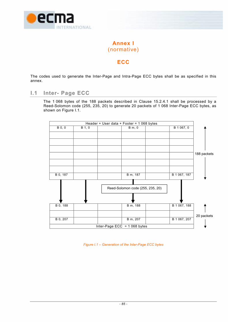
- 85 -
Annex I (normative)
ECC
The codes used to generate the Inter-Page and Intra-Page ECC bytes shall be as specified in this annex.
I.1 Inter- Page ECC
The 1 068 bytes of the 188 packets described in Clause 15.2.4.1 shall be processed by a Reed-Solomon code (255, 235, 20) to generate 20 packets of 1 068 Inter-Page ECC bytes, as shown on Figure I.1.
Header + User data + Footer = 1 068 bytes
B 0, 0 B 1, 0 B m, 0 B 1 067, 0
B 0, 187 B m, 187 B 1 067, 187
Figure I.1 – Generation of the Inter-Page ECC bytes
B 0, 188 B m, 188 B 1 067, 188
B 0, 207 B m, 207 B 1 067, 207
Inter-Page ECC = 1 068 bytes
Reed-Solomon code (255, 235, 20)
188 packets
20 packets

- 86 -
I.2 Intra-Page ECC
The 1 072 bytes packets of Clause 15.2.4.1 corresponding to User data + Inter-Page ECC bytes shall be first converted in 2 144 bytes packets through the 8 bits to 16 bits conversion table shown in Figure I.2.
data(hex) 15 14 13 12 11 10 9 8 7 6 5 4 3 2 1 0 Digit
00 0 0 0 0 0 0 0 0 0 0 0 1 1 0 1 0
01 0 0 0 0 0 0 0 0 0 0 1 0 0 1 0 1
02 0 0 0 0 0 0 0 0 0 0 1 0 1 0 0 1
: : :
: : :
80 0 0 0 0 1 0 1 0 0 0 0 0 0 1 0 0
B m, n 81 0 0 0 0 1 0 1 0 0 0 0 0 1 0 0 0 BB m,n
8bits, 1byte 82 0 0 0 0 1 0 1 0 0 0 0 1 0 0 0 0 16bits, 2bytes
: : :
: : :
FD 1 0 0 0 0 1 0 0 0 0 1 0 0 0 0 0
FE 1 0 0 0 0 1 0 0 1 0 0 0 0 0 0 0
FF 1 0 0 0 0 1 0 1 0 0 0 0 0 0 0 0
8bits, 1byte 16bits, 2bytes
Three "1"s for each16-bit (2-Byte) data
Look Up Table for 8bit - 16bit Conversion
B 0, 0 B 1, 0 … B 1 071, 0 BB 0, 0 BB 1, 0 … BB 1 071, 0
B 0, 1 B 1, 1 … B 1 071, 1 BB 0, 1 BB 1, 1 … BB 1 071, 1
: : :
B 0, n B 1, n … B 1 071, n BB 0, n BB 1, n … BB 1 071, n
: : : : : :
B 0, 207 B 1, 207 … B 1 071, 207 BB 0, 207 BB 1, 207 … BB 1 071, 207
1 072 bytes 1 072x2= 2 144 bytes
Figure I.2 – 8 to 16 bits conversion
These 2 144 bytes packets shall be then processed by the ECC/LDPC encoding of Figure I.3a, I.3b and I.3c to generate 560 Intra-Page ECC bytes added to each of the initial 1 072 bytes packets.
1 072 x 2 = 2 144 bytes
BB 0, n BB 1, n … BB m, n … BB1 071, n
C 0 C 1 C 2 C 3 C 4 C 5 C 6 C 7 134 x 2 134 x 2 134 x 2 134 x 2 134 x 2 134 x 2 134 x 2 134 x 2 = 268 = 268 = 268 = 268 = 268 = 268 = 268 = 268 bytes bytes bytes bytes bytes bytes bytes bytes
1 072 x 2 1 072 x 2 1 072 x 2 1 072 x 2 1 072 x 2 1 072 x 2 1 072 x 2 1 072 x 2 = 2 144 = 2 144 = 2 144 = 2 144 = 2 144 = 2 144 = 2 144 = 2 144
bits bits bits bits bits bits bits bits
D 0 D 1 D 2 … D i … D 2 143 R 0 R 1 … R 559
Q 0 Q 1 Q 2 Q 3 Q 4 Q 5 Q 6 Q 7 560 560 560 560 560 560 560 560 bits bits bits bits bits bits bits bits 70 70 70 70 70 70 70 70
bytes bytes bytes bytes bytes bytes bytes bytes
1 072 bytes Intra-Page ECC 560 bytes B 0, n B 1, n … B m, n … B 1 071, n B 1 072, n … B 1 631, n
Intra-Page ECC (LDPC redundancy)
Header + User Data + Footer
2 144 bytes = 2 144bits x 8
560 bits x 8 = 560 bytes
C k Q k
LDPC redundancy 560bits Intra-Page ECC
construction

- 87 -
Figure I.3a – Generation of the Intra-Page ECC bytes
Figure I.3b – Intra-Page ECC code structure
Figure I.3c – Intra-Page ECC code structure
I I I I … … … I 0 0 0 0 0 0 80 bits
I αααα1x1 αααα2x1 αααα3x1… … … 0 I 0 0 0 0 0 80 bits
I αααα1x2 αααα2x2 αααα3x2… … … 0 0 I 0 0 0 0 80 bits
H = I αααα1x3 αααα2x3 αααα3x3… … … 0 0 0 I 0 0 0 80 bits 560 bits Width
I αααα1x4 αααα2x4 αααα3x4… … … 0 0 0 0 I 0 0 80 bits
I αααα1x5 αααα2x5 αααα3x5… … … 0 0 0 0 0 I 0 80 bits
I αααα1x6 αααα2x6 αααα3x6… … … 0 0 0 0 0 0 I 80 bits
80 80 80 80 … … … 80 80 80 80 80 80 80
bits bits bits bits … … … bits bits bits bits bits bits bits
0 1 0 0 0 … … … 0 1 0 0 … … 0
0 0 1 0 0 … … … 0 0 1 0 :
0 0 0 1 0 … … … 0 0 0 1 . : 64
: : : . . . : 0 0 0 . . : bits
αααα = : : : . . . : 80 bits I' = : : : . . 0 80 bits
: : : . . . : : : : . 1
: : : . . 0 : : : 0
0 0 0 . 1 : : : :
1 0 0 … … … … … 0 0 0 0 … … 0
80 64
bits bits
αααα25x4
bits
( αααα26x3 )'
80
αααα25x3
I I'
αααα25x1
αααα25x2
( αααα26x1 )'
( αααα26x2 )'
Length
( αααα26x4 )'
( αααα26x5 )'
( αααα26x6 )'
64
bitsbits
αααα25x5
αααα25x6
2704
0 … … … … R j Initial value
x x x … … x … … x x D 0 D 1 D 2 D i D 2 142 D 2 143
R 0 R 1 R 2 … R j …
H 0, 0 H 1, 0 H 2, 0 … H i, 0 … H 2 143, 0 … H 2 703, 0 H 0, 1 H 1, 1 H 2, 1 … H i, 1 … H 2 143, 1 … H 2 703, 1 H 0, 2 H 1, 2 H 2, 2 … H i, 2 … H 2 143, 2 … H 2 703, 2
H = : : : : : : : : : H 0, j H 1, j H 2, j … H i, j … H 2 143, j … H 2 703, j
: : : : : : : : : H 0, 559 H 1, 559 H 2, 559 … H i, 559 … H 2 143, 559 … H 2 703, 559
H 2 143, j H 2 142, j H 0, j H 1, j H 2, j H i, j
D 0 D 2 D 1 R 559 D i ……… ……… D 2 143
For I = 0: 2 143 Rj = (Rj) xor (Hij and Di) End

- 88 -

- 89 -
Annex J (normative)
16 bits to Symbols conversion look-up table
The conversion of the 16-bits data in Symbols shall be done as shown in Table J.1.
Bits to One shall correspond to ON (illuminated) pixels.
Bits to Zero shall correspond to Off (non-illuminated) pixels.

- 90 -
Table J.1 – 16-bits data to Symbols conversion

- 91 -
Table J.1 – 16-bits data to Symbols conversion

- 92 -
Table J.1 – 16-bits data to Symbols conversion

- 93 -
Table J.1 – 16-bits data to Symbols conversion

- 94 -
Table J.1 – 16-bits data to Symbols conversion

- 95 -
Table J.1 – 16-bits data to Symbols conversion

- 96 -
Table J.1 – 16-bits data to Symbols conversion

- 97 -
Table J.1 – 16-bits data to Symbols conversion

- 98 -
Table J.1 – 16-bits data to Symbols conversion

- 99 -
Table J.1 – 16-bits data to Symbols conversion

- 100 -
Table J.1 – 16-bits data to Symbols conversion

- 101 -
Table J.1 – 16-bits data to Symbols conversion

- 102 -
Table J.1 – 16-bits data to Symbols conversion

- 103 -
Table J.1 – 16-bits data to Symbols conversion

- 104 -

- 105 -
Annex K (normative)
Finalizing data
The Finalizing data recorded in the Lead-out Zone shall be as shown in Table K.1.
The 41 finalizing bytes shall be recorded at the beginning of a Data Page filled with additional bytes containing Zero data.
Table K.1 – Final izing data
Item Format/ Meaning Bytes
Version of disk format 1 / HVD-R 200 GB 2
Version of Specific Disk Information n / Version number x 100 2
Disk category 1 / HVD-R, 2 / HVD-ROM 2
Disk size 1 / 120 mm 2
Disk capacity n / n Gbytes 2
Reserved Set to Zero 10
Energy density for permanent fixing n / n Joules.cm-2
2
Reserved Set to Zero 2
Hologram read energy n / n nanoJoules 2
Write strategy 1 / Sequential 1
Hologram maximum write energy n / n nanoJoules 2
Start track of user data n / Track address number 2
Start Sector of user data n / Sector address number 1
Start Channel bit of user data n / Channel bit number 2
End track of user data n / Track address number 2
End Sector of user data n / Sector address number 1
End Channel bit of user data n / Channel bit number 2
Amount of stored data n / n Gbytes 2

- 106 -

- 107 -
Annex L (normative)
Tracking/Addressing and Data Reading Channels
characteristics
L.1 Tracking/Addressing Channel characteristics
Analog signals and jitter shall be measured in the Tracking/Addressing Channel using the following circuit:
From reading
amplifier K1
Figure L.1 – Addressing Channel block diagram
The band-pass filter shall be of the 2nd
Order Bessel type with a bandwidth frequency of 20 Hz to 2 MHz.
L.2 Data Reading Channel characteristics
Data shall be detected in the Data Reading Channel by the following circuit:
Figure L.2 – Data Reading Channel block diagram
omparator Ed
dete
Band-
filt
Photo
Curreco
log/digital onverter
Decoder
Analog Jitter t
Trailin
Leadin
Data
g edge
g edge
est points
test pointnt/voltage nverter
Anac
detector array
Cpass
er
ge
ctor

- 108 -
L.2.1 Sync Marks detection
The Data Page Sync Mark shall be detected, as shown on Figure K.3a, by calculating the sum of the intensity of 12x12 (-6 to +6) pixels square for different positions of centre of this square in a range of 40x40 (-20 to +20) pixels around its supposed nominal position.
The position of the Data Page Sync Mark corresponds to the maximum of the detected sum.
S(x+x’, y+y’) is the pixel signal intensity on the photodetector array.
Figure L.3a – Example of detection process of the Data Page Sync Mark

- 109 -
The Sub-Page Sync Mark shall be detected, as shown on Figure L.3b, by calculating the sum of the intensity of 12x12 (-6 to +6) pixels square for different positions of centre of this square in a range of 40x40 (-20 to +20) pixels around its supposed nominal position
The position of the Sync Mark corresponds to the maximum of the detected sum.
Figure L.3b – Example of detection process of the Sub-Page Sync Mark

- 110 -
L.2.2 Symbol decoding
The Symbol decoding shall be performed by a correlation process, as shown on Figure L.4.
The data content of the Symbol shall be the data content of the filter Fi(x,y) giving the maximum of the multiplication signal Ci.
Figure L.4 – Symbol decoding

- 111 -
Annex M (normative)
Asymmetry measuring definition
The asymmetry of signals from mT and nT pits and lands shall be measured based on the following definitions. See Figure L.1.
mT pits and lands nT pits and lands mT pits and lands IH
IL IL bot IL top IH bot IH top 0 Level
Figure M.1 – Signal from tracking/addressing data with mT and nT pits and lands
1/2 [(IL top + IL bot) - (IH top + IH bot)] Asymmetry (mT-nT) = IL top - IL bot
where
IL and IH are the peak-to-peak values of the Tracking/Addressing Channel signals for mT and nT pits and lands, read under the conditions specified in 20.2.
IL top, IH top, IL bot, IH bot are the top and bottom levels of IL and IH.

- 112 -

- 113 -
Annex N (informative)
Office environment
N.1 Air cleanliness
Due to their construction and mode of operation, Holographic Disk Cartridges have considerable resistance to the effects of dust particles around and inside the disk drive. Consequently, it is not generally necessary to take special precautions to maintain a sufficiently low concentration of dust particles.
Operation in heavy concentrations of dust should be avoided, e.g. in a machine shop or on a building site.
Office environment implies an environment in which personnel may spend a full working day without protection and without suffering temporary or permanent discomfort.
N.2 Effects of operation
In the office environment (as well as other environments) it is possible for a holographic disk drive to degrade the quality of the written pixels if the reading energy is applied to a track for a long period of time.
The media manufacturer’s selection of the value for the maximum reading energy allowed in the User data Zones, as well as the drive manufacturer’s reading energy management method, should reflect this possibility and be designed to minimize any risk to data integrity.

- 114 -

- 115 -
Annex O (informative)
Transportation
O.1 General
As transportation occurs under a wide range of temperature and humidity variations, for different periods, by many methods of transport and in all parts of the world it is not possible to specify conditions for transportation or for packaging.
The following gives recommendations.
O.2 Packaging
The form of packaging should be agreed between sender and recipient or, in the absence of such agreement, is the responsibility of the sender. It should take account of the following hazards.
O.2.1 Temperature and humidity
Insulation and wrapping should be designed to maintain the following conditions during transportation.
O.2.1.1 Cartridges before f inalizing
Temperature 10°C to 30°C
Atmospheric pressure 60 kPa to 106 kPa
Relative Humidity 5% to 50%
Absolute air humidity 25g/m3 max.
Ambient light (shutter close) 135 µW/cm2
Duration 10 consecutive days max.
No condensation in or on the cartridge.
O.2.1.2 Cartridges after f inalizing
Temperature 5°C to 32°C
Atmospheric pressure 60 kPa to 106 kPa
Relative Humidity 5% to 80%
Absolute air humidity 25 g/m3 max.
Ambient light (shutter close) 135 µW/cm2
No condensation in or on the cartridge.
O.2.2 Impact loads and vibration
Avoid mechanical loads that would distort the shape of the cartridge.
Avoid dropping the cartridge.
Cartridges should be packed in a rigid box containing adequate shock absorbent material.
The final box should have a clean interior and a construction that provides sealing to prevent the ingress of dirt and moisture.

- 116 -
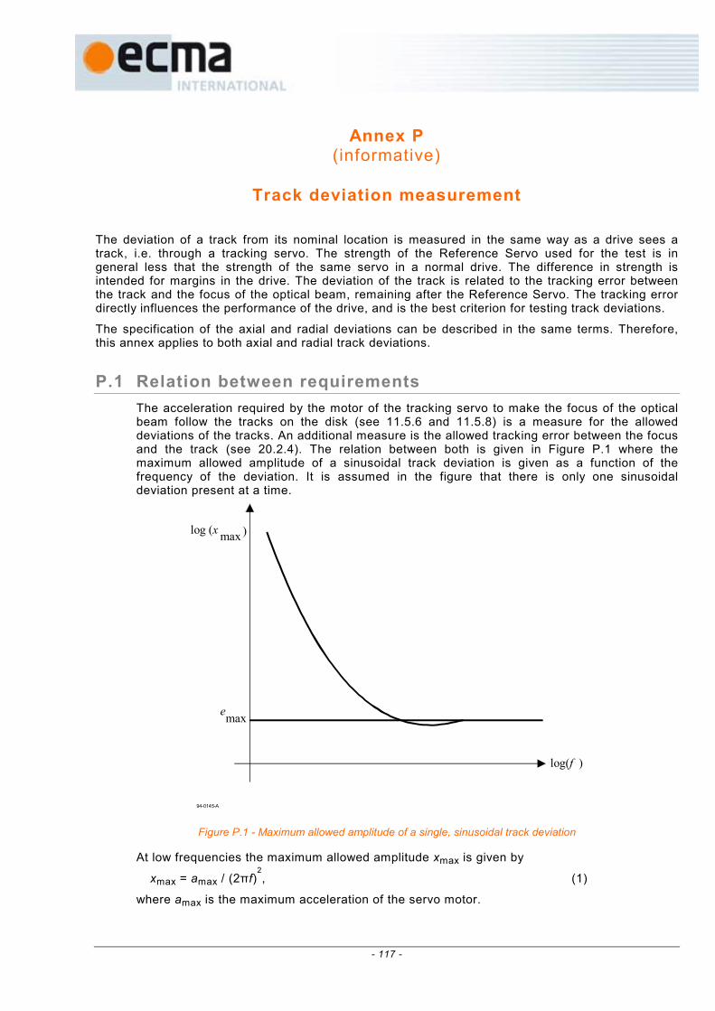
- 117 -
Annex P (informative)
Track deviation measurement
The deviation of a track from its nominal location is measured in the same way as a drive sees a track, i.e. through a tracking servo. The strength of the Reference Servo used for the test is in general less that the strength of the same servo in a normal drive. The difference in strength is intended for margins in the drive. The deviation of the track is related to the tracking error between the track and the focus of the optical beam, remaining after the Reference Servo. The tracking error directly influences the performance of the drive, and is the best criterion for testing track deviations.
The specification of the axial and radial deviations can be described in the same terms. Therefore, this annex applies to both axial and radial track deviations.
P.1 Relation between requirements
The acceleration required by the motor of the tracking servo to make the focus of the optical beam follow the tracks on the disk (see 11.5.6 and 11.5.8) is a measure for the allowed deviations of the tracks. An additional measure is the allowed tracking error between the focus and the track (see 20.2.4). The relation between both is given in Figure P.1 where the maximum allowed amplitude of a sinusoidal track deviation is given as a function of the frequency of the deviation. It is assumed in the figure that there is only one sinusoidal deviation present at a time.
94-0145-A
log (xmax )
emax
log(f )
Figure P.1 - Maximum allowed amplitude of a single, sinusoidal track deviation
At low frequencies the maximum allowed amplitude xmax is given by
xmax = amax / (2πf)2
, (1)
where amax is the maximum acceleration of the servo motor.

- 118 -
At high frequencies the maximum allowed amplitude xmax is given by
xmax = emax (2)
where emax is the maximum allowed tracking error. The connection between both frequency regions is given in P.3.
P.2 Reference Servo
The above restrictions of the track deviations are equal to the restriction of the track deviations for a Reference Servo. A Reference Servo has a well-defined transfer function, and reduces a single, sinusoidal track deviation with amplitude xmax to a tracking error emax as in Figure P.1.
The open-loop transfer function of the Reference Servo shall be
( )
0
0
cω
i1
ω
ci1
i
ω
c
1i
2
s ω
ω
ωωH
+
+
××=0
(3)
where i = -1 , ω = 2πf and ω0 = 2πf0, with f0 the 0 dB frequency of the open-loop transfer function. The constant c gives the cross-over frequencies of the lead-lag network of the servo:
the lead break frequency c
ff
01 = and the lag break frequency cff 02 ×= . The reduction of a
track deviation x to a tracking error e by the Reference Servo is given by
s+1
1=
Hx
e (4)
If the 0 dB frequency is specified as
max
max0
c=ω
e
a (5)
then a low-frequency track deviation with an acceleration amax will be reduced to a tracking error emax, and a high frequency track deviation will not be reduced. The curve in Figure P.1 is given by
xmax = emax 1 + Hs (6)
The maximum acceleration required from the motor of this Reference Servo is
amax (motor) = emax ω2 1 + Hs (7)
At low frequencies f > f0 / c applies
amax (motor) = amax (track) =c
ω max2
0e
(8)
Hence, it is permitted to use amax(motor) as specified for low frequencies in 11.5.6 and 11.5.8 for the calculation of ω0 of a Reference Servo.

- 119 -
P.3 Requirement for track deviations
The track deviations shall be such that, when tracking with a Reference Servo on a disk rotating at the specified frequency, the tracking error shall not be larger than emax during more than 10 µs.
The open-loop transfer function of the Reference Servo for axial and radial tracking shall be given by equation (3) within an accuracy such that |1 + H| does not differ by more than ± 20% from its nominal value in a bandwidth from 20 Hz to 150 kHz. The constant c shall be 3. The
0 dB frequency 2π
ω0 shall be given by equation (5), where amax and emax for axial and radial
tracking are specified in 11.5.6, 11.5.8 and 20.2.4.
P.4 Measurement implementation
Three possible implementations for axial or radial measurement systems have been given below.
Ha is the open-loop transfer function of the actual tracking servo of the drive. Hs is the transfer function for the Reference Servo as given in equation (3). x and y are the position of the track and the focus of the optical beam. es is the tracking error after a Reference Servo, the signal of which has to be checked according to the previous paragraph.
94-0081-B
Position sensorFilter 11 + HS
+
+y
ea
esx
Servo
Figure P.2 - Implementation of a Reference Servo by filtering the track position signal with the reduction characteristics
of the Reference Servo
94-0082-B
Hs
Ha
+
x
-
y
es
Ha
Figure P.3 - Implementation of a Reference Servo by changing the transfer function of the actual servo

- 120 -
94-0083-B
1+ Hs
1+ Ha
+
x
-
y
es
ea
Ha
Figure P.4 - Implementation of a Reference Servo by changing the tracking error of the actual servo
The optimum implementation depends on the characteristics Ha and Hs. Good results for motors in leaf springs are often obtained by using separate circuits in a low and high frequency channel. The implementation of Figure P.2 is used in the low-frequency channel, while that of Figures P.3 or P.4 is used in the high-frequency channel. The signals from both channels are added with a reversed cross-over filter to get the required tracking error. In the low-frequency channel one can also use the current through the motor as a measure of the acceleration of the motor, provided the latter is free from hysteresis. The current must be corrected for the transfer function of the motor and then be converted to a tracking error with a filter with a
transfer function 2
=ωx
e
a
e derived from equation (4).

- 121 -

- 122 -