Influence of uniform basement extension on faulting in cover sediments
8
Influence of uniform basement extension on faulting in cover sediments Tim Harper a , Haakon Fossen b, * , Jonny Hesthammer c a Geosphere Ltd, Netherton Farm, Sheepwash, Beaworthy, Devon EX21 5PL, UK b Department of Geology, University of Bergen, Allegt. 41, N-5007 Bergen, Norway c Statoil, N-5020 Bergen, Norway Received 6 December 1999; revised 1 June 2000; accepted 6 June 2000 Abstract Numerical predictions are compared with the results obtained from sandbox experiments intended to reproduce the effects of uniform basement extension. For mechanically homogeneous or uniformly layered sediments that are not strain-softened, faults are not expected to develop during uniform basement extension. Even in heterogeneous or strain-softening sediments subject to uniform basement extension, the only faults to develop reveal an irregular and uncharacteristic distribution of displacements along the fault plane. It is inferred that minor and inevitable gradients in strain rate are the most important reason why faulting was observed in the sandbox models. Irregularities such as topographic variation can also lead to faulting. Numerical experiments show that with increasing thickness of a basal elastic layer (rubber membranes in sandbox models) faulting of the cover sediments can cause the strain in the underlying elastic “basement” layer to become non-uniform. Faulting during uniform basement extension is controlled by irregularities particular to each example, and thus does not give rise to a characteristic structural style in the overlying sediments. Thus, sandbox experiments of this type cannot be used as templates for structural interpretation except for the rare case when the initial distribution of sediment and basement material properties are known and their influence is explored from extensive numerical experimentation. q 2001 Elsevier Science Ltd. All rights reserved. 1. Introduction Our understanding of geological deformation is continu- ously enhanced by means of field analysis, numerical simu- lation and physical modelling. As for the latter, sandbox experiments have proved to be a useful tool in the investiga- tion of structural development during extension as well as other deformation types. The extensive use of sandbox experiments to investigate extensional faulting has been summarised by Ishikawa and Otsuki (1995). These authors, innovatively applying strain gradients in sandbox experi- ments, showed that half grabens tended to develop in the presence of a strain gradient. In contrast, drawing on the results of previous modelling, Ishikawa and Otsuki (1995) concluded that horst and graben structures tended to develop in the presence of a homogeneously (uniformly) extending basement (uniform bulk extension/pure shear). Recent sandbox experiments intended to reproduce uniform basement extension are described by McClay and Ellis (1987a,b), Vendeville et al. (1987) and Vendeville and Cobbold (1988). In these experiments, the base of the moving wall of the sandbox was connected to the base of the fixed wall by a rubber membrane. The rubber membrane is referred to as “basement”. During all of these experi- ments, horst and graben systems evolved with end results strikingly similar to seismically imaged structures in natural rift systems. In particular, the structures produced by McClay and Ellis (1987a,b) were remarkably similar to extensional structures in the North Sea, some of which contain very large accumulations of hydrocarbons (e.g. the Gullfaks structure; Fossen and Hesthammer, 1998). Some of the sandbox results are thus of major economic as well as academic interest. In particular, accurate description of the tectonic “boundary conditions” is an essential pre-requisite of predicting subseismic structure by modelling the struc- tural history of a reservoir. It should be noted that uniform stretching of a basement (rubber sheet) that remains flat during extension is unrepre- sentative of most geological settings. A basement unit is always mechanically heterogeneous, with pre-existing weak faults and shear zones and weak, tilted layers. Strain is expected to concentrate on such basement structures and influence fault growth in the sedimentary cover. Rotation of basement blocks is inevitable, and contradicts the assump- tion of a flat basement throughout the strain history. Some of Journal of Structural Geology 23 (2001) 593–600 0191-8141/01/$ - see front matter q 2001 Elsevier Science Ltd. All rights reserved. PII: S0191-8141(00)00107-3 www.elsevier.nl/locate/jstrugeo * Corresponding author. E-mail address: [email protected] (H. Fossen).
-
Upload
tim-harper -
Category
Documents
-
view
218 -
download
4
Transcript of Influence of uniform basement extension on faulting in cover sediments
In¯uence of uniform basement extension on faulting in cover sediments
Tim Harpera, Haakon Fossenb,*, Jonny Hesthammerc
aGeosphere Ltd, Netherton Farm, Sheepwash, Beaworthy, Devon EX21 5PL, UKbDepartment of Geology, University of Bergen, Allegt. 41, N-5007 Bergen, Norway
cStatoil, N-5020 Bergen, Norway
Received 6 December 1999; revised 1 June 2000; accepted 6 June 2000
Abstract
Numerical predictions are compared with the results obtained from sandbox experiments intended to reproduce the effects of uniform
basement extension. For mechanically homogeneous or uniformly layered sediments that are not strain-softened, faults are not expected to
develop during uniform basement extension. Even in heterogeneous or strain-softening sediments subject to uniform basement extension, the
only faults to develop reveal an irregular and uncharacteristic distribution of displacements along the fault plane. It is inferred that minor and
inevitable gradients in strain rate are the most important reason why faulting was observed in the sandbox models.
Irregularities such as topographic variation can also lead to faulting. Numerical experiments show that with increasing thickness of a basal
elastic layer (rubber membranes in sandbox models) faulting of the cover sediments can cause the strain in the underlying elastic ªbasementº
layer to become non-uniform.
Faulting during uniform basement extension is controlled by irregularities particular to each example, and thus does not give rise to a
characteristic structural style in the overlying sediments. Thus, sandbox experiments of this type cannot be used as templates for structural
interpretation except for the rare case when the initial distribution of sediment and basement material properties are known and their
in¯uence is explored from extensive numerical experimentation. q 2001 Elsevier Science Ltd. All rights reserved.
1. Introduction
Our understanding of geological deformation is continu-
ously enhanced by means of ®eld analysis, numerical simu-
lation and physical modelling. As for the latter, sandbox
experiments have proved to be a useful tool in the investiga-
tion of structural development during extension as well as
other deformation types. The extensive use of sandbox
experiments to investigate extensional faulting has been
summarised by Ishikawa and Otsuki (1995). These authors,
innovatively applying strain gradients in sandbox experi-
ments, showed that half grabens tended to develop in the
presence of a strain gradient. In contrast, drawing on the
results of previous modelling, Ishikawa and Otsuki (1995)
concluded that horst and graben structures tended to develop
in the presence of a homogeneously (uniformly) extending
basement (uniform bulk extension/pure shear).
Recent sandbox experiments intended to reproduce
uniform basement extension are described by McClay and
Ellis (1987a,b), Vendeville et al. (1987) and Vendeville and
Cobbold (1988). In these experiments, the base of the
moving wall of the sandbox was connected to the base of
the ®xed wall by a rubber membrane. The rubber membrane
is referred to as ªbasementº. During all of these experi-
ments, horst and graben systems evolved with end results
strikingly similar to seismically imaged structures in natural
rift systems. In particular, the structures produced by
McClay and Ellis (1987a,b) were remarkably similar to
extensional structures in the North Sea, some of which
contain very large accumulations of hydrocarbons (e.g. the
Gullfaks structure; Fossen and Hesthammer, 1998). Some of
the sandbox results are thus of major economic as well as
academic interest. In particular, accurate description of the
tectonic ªboundary conditionsº is an essential pre-requisite
of predicting subseismic structure by modelling the struc-
tural history of a reservoir.
It should be noted that uniform stretching of a basement
(rubber sheet) that remains ¯at during extension is unrepre-
sentative of most geological settings. A basement unit is
always mechanically heterogeneous, with pre-existing
weak faults and shear zones and weak, tilted layers. Strain
is expected to concentrate on such basement structures and
in¯uence fault growth in the sedimentary cover. Rotation of
basement blocks is inevitable, and contradicts the assump-
tion of a ¯at basement throughout the strain history. Some of
Journal of Structural Geology 23 (2001) 593±600
0191-8141/01/$ - see front matter q 2001 Elsevier Science Ltd. All rights reserved.
PII: S0191-8141(00)00107-3
www.elsevier.nl/locate/jstrugeo
* Corresponding author.
E-mail address: [email protected] (H. Fossen).
these sources of non-uniform basement deformation are
eliminated if the basement±cover interface is represented
as a low-angle detachment fault. However, in this case the
detachment is better modelled as a low-friction slip surface
rather than an extension-controlling ªrubber sheetº. The aim
of this paper, however, is not to model a speci®c geologic
example, but to examine the effect of uniform basement
extension which, as noted above, has provided apparently
important results in the past. In pursuing the primary objec-
tive of determining the geological relevance of the structural
styles observed in previous sandbox analogues, the investi-
gation serves also to emphasise that uniform basement
extension is geologically improbable.
Below we present numerical experiments and compare
the numerical predictions with the results obtained from
the sandbox experiments intended to reproduce the effects
of uniform basement strain. In particular, the numerical
analyses suggest that the uniform extension condition
described by McClay and Ellis gives rise to essentially
homogeneous strain (no major faults). Consequently, we
emphasise that, despite the remarkable similarity of struc-
ture developed in the sandbox experiments of McClay and
Ellis and those of ®eld examples such as Gullfaks, such
structural arrangements should not be interpreted to result
from uniform basement extension. To the contrary, they
could be interpreted to be partly a consequence of inhomo-
geneous basement extension. Such structural arrangements
would be more consistent with the conclusions of Ishikawa
and Otsuki (1995).
2. Modelling faulting in geological materials
Certain aspects of fault initiation and propagation in
geological materials are sometimes misunderstood in struc-
tural geology. For example, the belief that local weaknesses,
such as grain boundaries or microcracks, are required for
fault initiation in a deforming continuum is not uncommon.
Such weaknesses, present in physical models but usually not
in numerical models, have no signi®cant effect on the style
of faulting. Failing to recognise this fact can lead to an
unfounded preference for sandbox results relative to the
output of numerical models. Consequently, we restate
some of the fundamental conclusions drawn by previous
workers that lucidly explain localisation during shear
deformation.
Localisation is the spontaneous formation of zones of
concentrated deformation. Cundall (1990) explained that
the possibility for localisation arises when one or more
stress components at any location in a continuum are able
to decrease with increasing strain. The strain then tends to
be concentrated at this location. Cundall (1990) listed three
ways in which the stress at a point can decrease with
increasing strain: (a) large geometric distortionsÐbuckling
of a thin beam is an extreme example of this; (b) material
softening, by which the intrinsic material becomes weaker,
e.g. a dilatant material becomes looser and hence weaker;
and (c) a change in stress state such that at least one com-
ponent decreases. Cundall (1990) developed this third
effect, ªstress state softeningº, emphasising that it can
occur even when a material is getting stronger (hardening).
These effects occur in a deforming continuum and do not
rely on the presence of pre-existing ¯aws, discontinuities or
other form of heterogeneity.
Heterogeneity is a typical characteristic of geological
materials. It can affect the locus of initiation of a shear
band in that localisation occurs in the immediate vicinity
of a hard or soft ªinclusionº (Desrues, 1990). Nevertheless,
the overall style of deformation is independent of micro-
scale heterogeneity.
Examining the potential for modelling fault genesis in an
initial continuum, Cundall (1990) investigated the in¯uence
of element size and loading rate on the results, and also large
strain effects. Poliakov et al. (1993) reviewed the suitability
of the FLAC algorithm used here for simulating sedi-
mentary rock behaviour. Readers requiring a more detailed
description of the processes of localisation than the brief
comments given here are referred to Jenkins (1990),
Poliakov et al. (1993), Vermeer (1990), MuÈhlaus and
Vardoulakis (1987) and Rudnicki and Rice (1975). The
paper by Poliakov et al. (1993) also includes a discussion
of shear band formation in numerical models including the
mesh-dependence when modelling strain-softening materials.
3. Description of the numerical method and conditionsused here
Numerical experiments were conducted using the geo-
mechanical code FLAC 3.4 (Fast Lagrangian Analysis of
Continua; Itasca Consulting Group Inc., 1998). FLAC is an
explicit, plane strain ®nite difference method, which uses
Lagrangian analysis, and explicitly solves the dynamic
equations of motion. The stresses, velocities and displace-
ments at each grid point are calculated for each time step.
Incremental displacements are added to the coordinates so
that the grid moves and deforms with the material it repre-
sents (the Lagrangian formulation). Each element in FLAC
behaves according to a prescribed linear or non-linear stress/
strain law in response to the applied forces and boundary
conditions. Linear elastic or elastic-perfectly plastic proper-
ties were used in the present experiments.
FLAC is able to model the development and evolution of
shear bands. This is partly because FLAC is formulated
using the dynamic equations of motion that are damped to
achieve static or pseudo-static solutions (i.e. the kinetic
energy that accompanies shear band formation is released
and dissipated in a physically realistic way). The thickness
of the shear bands depends upon the smallest width that can
be resolved by the grid. Almost invariably, this width is
much greater than the actual size of a shear band (fault) in
a brittle material. Numerically developed shear bands may
T. Harper et al. / Journal of Structural Geology 23 (2001) 593±600594

vary in thickness from one zone if the band is parallel to grid
axes, to 3±4 zones if the band is inclined. This effect bears
similarities to sandbox experiments, where the relatively
large grain size results in shear zones rather than discrete
faults.
Advantages of such numerical experiments over physical
models include the complete control of boundary condi-
tions, the absence of scaling problems and complete control
of each step during the deformation history. The current
experiments were conducted using FLAC in large strain
mode directly at the true scale of a representative North
Sea-type reservoir sequence (initially 2 km pre-compaction
thickness and 10 km in length).
In most cases the sediments were represented as a homo-
geneous sand with the following properties: shear modulus�3 £ 107 Pa; bulk modulus � 1 £ 108 Pa; buoyant density�1000 kg/m3; cohesion � 0; friction � 358; tensile strength �0. In one additional experiment, two clay layers were included
with the following properties: shear modulus� 1 £ 108 Pa;
bulk modulus� 3 £ 108 Pa; buoyant density� 1000 kg/m3;
cohesion� 8 £ 103 Pa; friction� 158; tensile strength� 0.
With certain exceptions the sediments were modelled as
neither strain-softening nor as strain-hardening, i.e. elas-
tic±perfectly plastic, Mohr±Coulomb material. Properties
of the elastic basement layer are given in Appendix A.
Although a strain-softening material is more prone to
produce shear bands, as noted above, Cundall (1990)
emphasised that ªfaultsº can develop naturally in FLAC
and other models without the need to invoke complications
such as strain-softening.
Reference points for recording of the history of displace-
ments and shear stresses were equally spaced inside the
model 1.5 km above the base and at the base, as shown in
Fig. 1a.
The following are the main types of experiments per-
formed with cover sediments above a uniformly extending
basement surface: 1) extension of a homogeneous sand
sequence; 2) extension of homogeneous sand with two
clay layers; 3) extension of a sand sequence with hetero-
geneous mechanical properties and two homogeneous clay
layers; 4) extension of a sand having an initial density
heterogeneity; and 5) extension of strain-softening sand.
Experiments were also conducted of the extension of homo-
geneous sand above a non-uniformly extending basement.
4. Results
4.1. Extension above a uniformly stretching basement
To reproduce the second experimental series of McClay
and Ellis (1987a), or the ®rst series of Vendeville et al.
(1987), a 100 m thick elastic layer at the base of the
sequence was overlain by 1.9 km thick Mohr±Coulomb
material with properties as outlined above (Fig. 1a). The
elastic layer corresponds to the rubber sheet in the sandbox
models, whereas the Mohr±Coulomb material corresponds
to the sand. The base of the model, i.e. immediately below
the rubber membrane, is a frictionless (roller) boundary.
Uniform basement extension was obtained, as a result of
the uniform, linear nature of the elastic layer. Additional
comments on the in¯uence of the sediment deformation
on the uniformity or of the deformation on the elastic
membrane (basement) are given in Section 4.4.
No signi®cant structures developed during the stretching
history, which was taken to 100% extension (Fig. 1b). The
very minor variation of cumulative shear strain shown may
be an artefact relating to the model boundaries (in compari-
son, the models by McClay and Ellis (1987a,b) produced a
total of 50% extension). The resulting homogeneous incre-
mental, as well as ®nite, strain is con®rmed by monitoring
the rate of extension of the individual reference points at the
base of the model (Fig. 1a and Fig. 2a) and by shear stress
histories of the sedimentary cover (Fig. 1a and Fig. 3a). The
®nite deformation state is seen to be homogeneous pure
shear, as opposed to the heterogeneous strain produced in
the sandbox experiments. The mechanical explanation for
the homogeneous ®nite strain is directly related to the
uniformity of the strain of the uniform elastic basement.
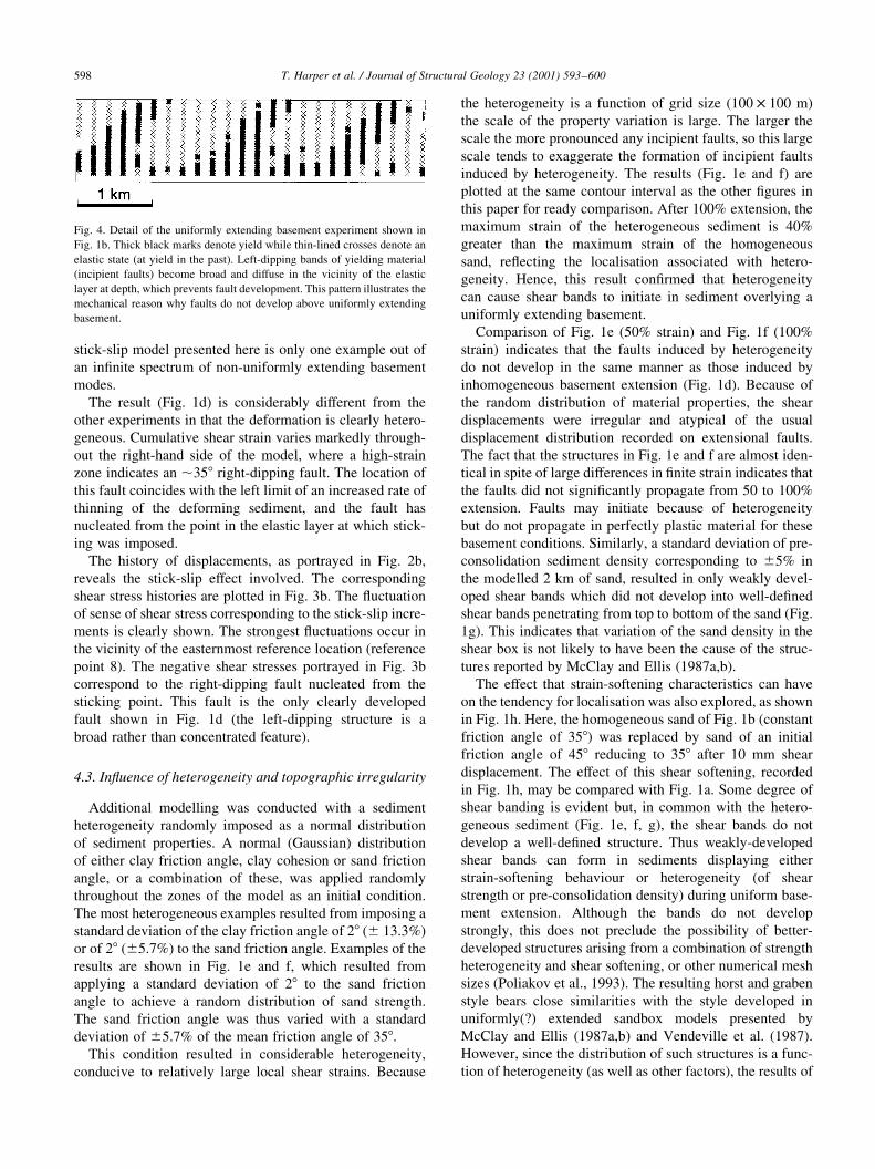
Fig. 4 shows a detail of the state of the sediments shown
in Fig. 1b. It is evident that there are dipping bands of
sediment at yield but that these bands become diffuse
(broader) at depth in the vicinity of the basement. Outside
these bands, yield at an earlier (post-consolidation) phase of
the extension is indicative of the evolving nature of the
pattern of incipient shear bands, none of which becomes a
concentrated zone of shear strain.
An additional experiment was performed, where a
sequence had an elastic layer at the base with an elastic
modulus 10 times less than that of all the other models
(i.e. very much softer). The result of this experiment (not
shown here) is similar to the one above, implying that
softening the modulus of the elastic layer has no effect on
the result.
An additional uniformly stretching basement experiment
was performed. This experiment was similar to the one
described above, except that two clay layers were intro-
duced in the upper half of the model (properties listed
above). The purpose of this run was to investigate the effect
of such heterogeneity on the deformation.
The distribution of cumulative shear strain (Fig. 1c) is
very similar to that obtained for homogeneous sand.
Hence, it appears that normal lithological (rheological)
strati®cation does not change the observations from the
®rst experiment, i.e. that the extensional strain above a
uniformly extending basement is homogeneous and thus
fails to produce structures.
4.2. Extension above a non-uniformly stretching basement
Having noticed that a uniformly extending basement fails
to produce structures in its cover, an experiment was
T. Harper et al. / Journal of Structural Geology 23 (2001) 593±600 595

Fig. 1. (a) Initial set-up of the experiments, showing the constant velocity applied to the right-hand side of the model and reference points for the measurements
shown in Figs. 2 and 3. (b) Cumulative shear strain after 100% extension of the homogeneous sand sequence above a uniformly extending basement. No
localisation (faulting) is evident, simply a gentle gradient of cumulative shear strain. (c) Cumulative shear strain for the model of homogeneous sand including
two clay layers. Note that the distribution of cumulative shear strain is similar to (b) and that the clay layers clearly demonstrate the lack of structure. (d)
Experiment where the elastic layer (rubber membrane of McClay and Ellis, 1987a,b) was extended irregularly. A right-dipping fault is particularly well
developed in the right-hand side of the model. (e) Result after 50% extension of a two-clay layer model similar to (c), but with heterogeneity (varying friction
angle throughout the sand). Note localisation of shear strain to create conjugate structures with irregular displacement distribution; (f) same as (e) but after
100% extension. The result is similar to (e) with additional homogeneous pure shear. (g) Cumulative shear strain after 50% uniform extension of sediments of
density varying with a standard deviation equivalent to ^5%. (h) Cumulative shear strain after 50% uniform extension of homogeneous strain-softening sand.
See text for discussion.
performed in which the elastic layer (rubber membrane of
McClay and Ellis, 1987a,b and Vendeville et al., 1987) was
subjected to heterogeneous extension. The 8 km on the left
of the elastic layer was alternately prevented from extending
and allowed to extend. A stick-slip behaviour of the elastic
layer was thus modelled. The right-hand 20% of the
sequence was allowed to extend continuously and homo-
geneously, but a point located one-®fth from the right end
of the model was assumed to be subject to stick-slip
behaviour (Fig. 1d). The 80% to the left of this stick-slip
point alternately stretched or experienced constant strain. In
this case, only 50% extension was modelled. The simple
T. Harper et al. / Journal of Structural Geology 23 (2001) 593±600 597
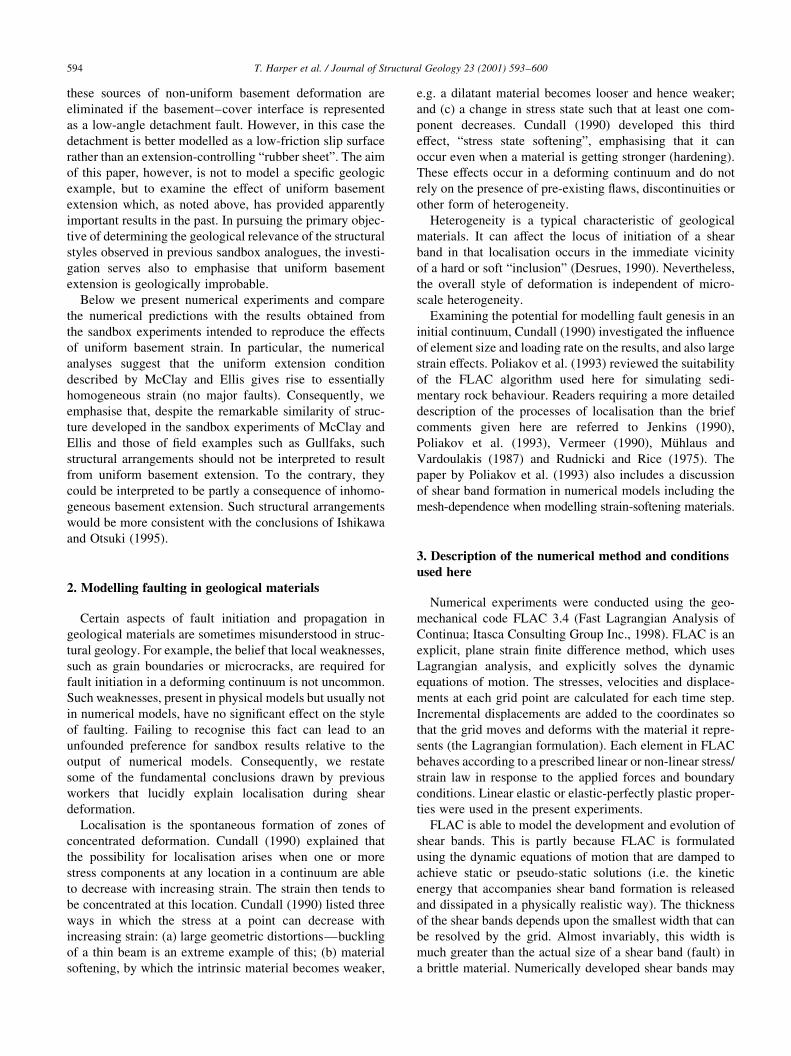
Fig. 3. Shear stress histories of the reference points shown in Fig. 1a for (a)
the experiment with homogeneously extending basement, and (b) hetero-
geneously-extending basement. In (a) the shear stresses oscillate as the
deformation progresses, but the ¯uctuation is essentially centred about
zero and individual reference point curves are indistinguishable. In (b) the
¯uctuation of shear stress corresponding to the stick-slip increments is
clearly portrayed. The strongest ¯uctuations (thick black line) occur in
the vicinity of the reference location 8 in the model (see Fig. 1a). The
negative shear stress corresponds to the right-dipping fault nucleated
from the sticking point. The oscillatory nature of the shear stress re¯ects
the nature of the FLAC formulation and the boundary conditions applied in
this modelling. The dynamic equations of motion are included in the formu-
lation with inertial terms and the generation and dissipation of kinetic
energy. Increments of work are done on the sedimentary pile at each
time step corresponding to the constant velocity boundary condition.
Fig. 2. Horizontal displacement versus the displacement of the right-hand
end of the sequence for (a) the experiment with homogeneously extending
basement, and (b) the experiment where the elastic layer was extended
irregularly. The lines represent the displacement of the reference points
shown in Fig. 1a. Note that the rate of extension is almost perfectly linear
in (a) and step-like non-linear in (b).
stick-slip model presented here is only one example out of
an in®nite spectrum of non-uniformly extending basement
modes.
The result (Fig. 1d) is considerably different from the
other experiments in that the deformation is clearly hetero-
geneous. Cumulative shear strain varies markedly through-
out the right-hand side of the model, where a high-strain
zone indicates an ,358 right-dipping fault. The location of
this fault coincides with the left limit of an increased rate of
thinning of the deforming sediment, and the fault has
nucleated from the point in the elastic layer at which stick-
ing was imposed.
The history of displacements, as portrayed in Fig. 2b,
reveals the stick-slip effect involved. The corresponding
shear stress histories are plotted in Fig. 3b. The ¯uctuation
of sense of shear stress corresponding to the stick-slip incre-
ments is clearly shown. The strongest ¯uctuations occur in
the vicinity of the easternmost reference location (reference
point 8). The negative shear stresses portrayed in Fig. 3b
correspond to the right-dipping fault nucleated from the
sticking point. This fault is the only clearly developed
fault shown in Fig. 1d (the left-dipping structure is a
broad rather than concentrated feature).
4.3. In¯uence of heterogeneity and topographic irregularity
Additional modelling was conducted with a sediment
heterogeneity randomly imposed as a normal distribution
of sediment properties. A normal (Gaussian) distribution
of either clay friction angle, clay cohesion or sand friction
angle, or a combination of these, was applied randomly
throughout the zones of the model as an initial condition.
The most heterogeneous examples resulted from imposing a
standard deviation of the clay friction angle of 28 (^ 13.3%)
or of 28 (^5.7%) to the sand friction angle. Examples of the
results are shown in Fig. 1e and f, which resulted from
applying a standard deviation of 28 to the sand friction
angle to achieve a random distribution of sand strength.
The sand friction angle was thus varied with a standard
deviation of ^5.7% of the mean friction angle of 358.This condition resulted in considerable heterogeneity,
conducive to relatively large local shear strains. Because
the heterogeneity is a function of grid size (100 £ 100 m)
the scale of the property variation is large. The larger the
scale the more pronounced any incipient faults, so this large
scale tends to exaggerate the formation of incipient faults
induced by heterogeneity. The results (Fig. 1e and f) are
plotted at the same contour interval as the other ®gures in
this paper for ready comparison. After 100% extension, the
maximum strain of the heterogeneous sediment is 40%
greater than the maximum strain of the homogeneous
sand, re¯ecting the localisation associated with hetero-
geneity. Hence, this result con®rmed that heterogeneity
can cause shear bands to initiate in sediment overlying a
uniformly extending basement.
Comparison of Fig. 1e (50% strain) and Fig. 1f (100%
strain) indicates that the faults induced by heterogeneity
do not develop in the same manner as those induced by
inhomogeneous basement extension (Fig. 1d). Because of
the random distribution of material properties, the shear
displacements were irregular and atypical of the usual
displacement distribution recorded on extensional faults.
The fact that the structures in Fig. 1e and f are almost iden-
tical in spite of large differences in ®nite strain indicates that
the faults did not signi®cantly propagate from 50 to 100%
extension. Faults may initiate because of heterogeneity
but do not propagate in perfectly plastic material for these
basement conditions. Similarly, a standard deviation of pre-
consolidation sediment density corresponding to ^5% in
the modelled 2 km of sand, resulted in only weakly devel-
oped shear bands which did not develop into well-de®ned
shear bands penetrating from top to bottom of the sand (Fig.
1g). This indicates that variation of the sand density in the
shear box is not likely to have been the cause of the struc-
tures reported by McClay and Ellis (1987a,b).
The effect that strain-softening characteristics can have
on the tendency for localisation was also explored, as shown
in Fig. 1h. Here, the homogeneous sand of Fig. 1b (constant
friction angle of 358) was replaced by sand of an initial
friction angle of 458 reducing to 358 after 10 mm shear
displacement. The effect of this shear softening, recorded
in Fig. 1h, may be compared with Fig. 1a. Some degree of
shear banding is evident but, in common with the hetero-
geneous sediment (Fig. 1e, f, g), the shear bands do not
develop a well-de®ned structure. Thus weakly-developed
shear bands can form in sediments displaying either
strain-softening behaviour or heterogeneity (of shear
strength or pre-consolidation density) during uniform base-
ment extension. Although the bands do not develop
strongly, this does not preclude the possibility of better-
developed structures arising from a combination of strength
heterogeneity and shear softening, or other numerical mesh
sizes (Poliakov et al., 1993). The resulting horst and graben
style bears close similarities with the style developed in
uniformly(?) extended sandbox models presented by
McClay and Ellis (1987a,b) and Vendeville et al. (1987).
However, since the distribution of such structures is a func-
tion of heterogeneity (as well as other factors), the results of
T. Harper et al. / Journal of Structural Geology 23 (2001) 593±600598
Fig. 4. Detail of the uniformly extending basement experiment shown in
Fig. 1b. Thick black marks denote yield while thin-lined crosses denote an
elastic state (at yield in the past). Left-dipping bands of yielding material
(incipient faults) become broad and diffuse in the vicinity of the elastic
layer at depth, which prevents fault development. This pattern illustrates the
mechanical reason why faults do not develop above uniformly extending
basement.
such sandbox models cannot be used as templates for struc-
tural interpretation (e.g. McClay, 1995) unless the distribu-
tion of sediment material properties are known and their
in¯uence investigated by an exhaustive series of numerical
experiments.
Mandl (1988) reported a numerical experiment whereby
shear band formation was initiated by imposing a notch in
the sediment sequence overlying uniformly extending base-
ment. This implies that topographic irregularity can also
cause fault initiation. Again, the results are of no value as
structural templates without a supporting programme simi-
lar to that mentioned above.
4.4. Sediment-basement coupling
Uniform basement extension was achieved in our experi-
ments by means of a linearly elastic layer at the base of the
model. Preliminary numerical investigations of the in¯u-
ence of developing faults in the cover sediments revealed
that the initially uniform extension of the elastic layer can
become non-uniform if conditions in the cover sediment
sequence are such that faults do after all develop in the
cover. In our preliminary experiments this could be
achieved by doubling the thickness of the elastic basement
to 200 m rather than attempting to model a (relatively thin)
membrane as used to represent the sandbox results which
motivated this investigation. It was noted that if faulting in
the cover can develop suf®ciently to cause a local thinning
of the basement layer, then the consequent local reduction in
basement thickness simply led to a local increase of base-
ment strain. Of particular interest, was that the local base-
ment thinning was not stationary as extension progressed,
such that the basement-cover coupling resulted in a quasi-
periodic evolution of the geometry of deformation. Further
exploration of this interesting behaviour was deemed
beyond the scope of this investigation. Thus we infer that
not only does a non-uniformity of basement extension give
rise to faults in the overlying sediment but that the reverse
also occurs, i.e. the sediment and basement are coupled.
Because coupling was only observed when the thickness
of the elastic layer in our models exceeded a certain
value, we expect that the effect may not be observed in
sandbox models using thin basal rubber membranes.
Note that the basement in these models was stronger than
the cover in that no plastic yield criterion is included in the
description of the basement constitutive behaviourÐthe
basement simply remains linearly elastic for all applied
stresses. It therefore follows from the results that the
cover sediments can in¯uence the basement rocks regard-
less of relative strength.
The numerical results reported by Mandl (1988) were
achieved using a boundary condition whereby the basement
displacements were forced to be uniform throughout the
experiment. Our preliminary results thus suggest that such
a boundary condition can yield misleading results.
5. Discussion
Uniform basement extension gives rise to essentially
homogeneous strain of homogeneous sand. No signi®cant
structures are developed in this case unless the sand has
strain-softening properties. Even with strongly strain-
softening sand, only weakly developed faults with an atypi-
cal displacement distribution were generated during our
experiments. Thus, the results of previous sandbox experi-
ments intended to represent a uniform basement extension
are misleading. Softening the modulus of the elastic layer
makes no difference to the results, nor does inclusion of two
clay layers. However, structure did develop when sticking
of the elastic membrane was simulated.
It is inferred that the rubber membrane used in the experi-
ments by McClay and Ellis (1987a,b) and Vendeville et al.
(1987) did not extend uniformly during the course of their
experiments. Mechanical heterogeneity of the sand might
have played a part in the initiation of faults but any such
heterogeneity-initiated faults are not likely to have propa-
gated and formed prominent structures as seen in the sand-
box experiments. We have no evidence that the sand was not
strain-softened and, although improbable, the possibility
that faulting initiated in response to heterogeneity and
propagated in response to strain-softening cannot be entirely
eliminated. The sand used in the physical experiments was
loose and probably not strain-softened, but if a contribution
to faulting by softening is nevertheless assumed, we note
that the effect is shown here to be limited under conditions
of uniform basement extension. As indicated by the experi-
ment with homogeneous strain-softening sand (Fig. 1h),
fault propagation with the assistance of strain-softening
does not lead to well-developed concentrations of shear
strain when controlled by uniform basement extension.
McClay and Ellis (1987a) report some early hetero-
geneous extension of the rubber sheet (10±15% extension),
but we suspect that the rubber sheet may have extended
heterogeneously also at higher extensions. The later hetero-
geneity of extension may not have been large, as it was not
recognised.
These ®ndings emphasise two important points; 1) minor
heterogeneity of basement extension is suf®cient to nucleate
faults, and 2) although not the only in¯uential factor, the
location of such heterogeneity in¯uences the position,
spacing and dip direction of faults. These discoveries call
for further numerical exploration of models with hetero-
geneously extending basements, where their sensitivity to
variations in typical basement and cover heterogeneity,
including typical lithological variations, should be the
focus.
Where basement extension is entirely or largely uniform,
as concluded by Ishikawa and Otsuki (1995), horst and
graben style will predominate (where conditions have been
suitable for faults to initiate and propagate). It is stressed,
however, that the distribution of faults will be a function of
the irregularities of basement extension, sediment properties
T. Harper et al. / Journal of Structural Geology 23 (2001) 593±600 599
(other than uniform layering) and topography. Relatively
straightforward numerical modelling can be used to assess
the in¯uence of each of these.
6. Conclusions
Our conclusions may be summarised as follows:
1. Well-de®ned faults do not form in layered but otherwise
homogeneous sediments subject to uniform extension of
the underlying basement.
2. Faults can initiate in heterogeneous sediments subjected
to uniform basement extension in response to the hetero-
geneity. These faults do not evolve into clear fault
structures in sediment that is not strain-softening.
Strain-softening alone is not suf®cient to give prominent
structures under these conditions. We have not attempted
to eliminate the possibility that heterogeneous strain-
softening sediments subject to uniform basement exten-
sion could give rise to well-developed faults because the
distribution of any such structures would also be a func-
tion of the irregularities (heterogeneity) that in¯uenced
fault initiation. Irregularities such as the topography can
also lead to faulting.
3. Faults formed in cover sediments overlying an initially
uniformly extending basement, in response to hetero-
geneity and/or topographic irregularity, can give rise to
non-uniform basement extension by means of a coupling
effect as extension progresses.
4. Uniform basement extension, in itself a geologically
improbable condition, does not give rise to a character-
istic structural style in the overlying sediments that can
be used as a single structural template for interpretation
purposes.
Acknowledgements
We thank Statoil for ®nancial support. Peter Cundall
kindly provided comments that helped us to clarify the
paper. Detailed reviews by Bruno Vendeville and Steve
McKinnon as well as comments by Ken McClay on an
earlier version are also appreciated.
Appendix A. Experimental details
An initial 2000 zone grid was scaled to represent a 10 km
long by 2 km deep section. The sides and base of the model
were ®xed normal to the boundary and free in the plane of
the boundary (i.e. roller boundaries). The model was ®rst
consolidated under gravity as a linear elastic material.
Excepting the zones immediately adjacent to the base of
the model, the material was then given perfectly plastic,
Mohr±Coulomb properties and further consolidated. The
properties of the basal elastic layer were: bulk modulus �1 £ 108 Pa; shear modulus � 0.64 £ 108 Pa. The material
was extended at a strain rate of 1025 per calculation cycle by
applying a constant velocity to the right boundary while the
left boundary remained ®xed. The effect of sticking of a
basal membrane in a sandbox was investigated by sequen-
tially and repeatedly imposing a zero velocity condition on
basal gridpoints 2±80 for periods of 5000 cycles and then
restoring the roller boundary condition.
References
Cundall, P., 1990. Numerical modelling of jointed and faulted rock. In:
Rossmanith, A. (Ed.). Mechanics of Jointed and Faulted Rock. Balkema,
Rotterdam, pp. 11±18.
Desrues, J., 1990. Shear band initiation in granular materials: experimenta-
tion and theory. In: Darve, F. (Ed.). Geomaterials, Constitutive Equa-
tions and Modelling. Elsevier, Oxford, pp. 283±310.
Ishikawa, M., Otsuki, K., 1995. Effects of strain gradient on asymmetry of
experimental normal fault systems. Journal of Structural Geology 17,
1047±1053.
Itasca Consulting Group Inc., 1998. FLAC (Fast Lagrangian Analysis of
Continua), version 3.4. ICG, Minneapolis.
Jenkins, J.T., 1990. Localization in granular materials. Applied Mechanics
Review 43, 194±195.
Fossen, H., Hesthammer, J., 1998. Structural geology of the Gullfaks Field,
northern North Sea. In: Coward, M.P., Johnson, H., Daltaban, T.S.
(Eds.). Structural Geology in Reservoir Characterization. Geological
Society Special Publication 127, pp. 231±261.
Mandl, G., 1988. Mechanics of Tectonic Faulting. Elsevier, Amsterdam.
McClay, K.R., 1995. 2D and 3D analogue modelling of extensional fault
structures: templates for seismic interpretation. Petroleum Geoscience
1, 163±178.
McClay, K.R., Ellis, P.G., 1987aa. Analogue models of extensional fault
geometries. In: Coward, M.P., Dewey, J.F., Hancock, P.L. (Eds.).
Continental Extensional Tectonics. Geological Society Special Publica-
tion 28, pp. 109±125.
McClay, K.R., Ellis, P.G., 1987bb. Geometries of extensional fault systems
developed in model experiments. Geology 15, 341±344.
MuÈhlaus, H.-B., Vardoulakis, I., 1987. The thickness of shear bands in
granular materials. Geotechnique 37, 271±283.
Poliakov, A.N.B., Podladchikov, Yu., Talbot, C., 1993. Initiation of salt
diapirs with frictional overburdens: numerical experiments. Tectono-
physics 228, 199±210.
Rudnicki, J.W., Rice, J.R., 1975. Conditions for the localization of the
deformation in pressure-sensitive dilatant materials. Journal of
Mechanics and Physics of Solids 23, 371±394.
Vendeville, B., Cobbold, P.R., 1988. How normal faulting and sedimenta-
tion interact to produce listric fault pro®les and stratigraphic wedges.
Journal of Structural Geology 10, 649±659.
Vendeville, B., Cobbold, P.R., Davy, P., Brun, J.P., Choukroune, P., 1987.
Physical models of extensional tectonics at various scales. In: Coward,
M.P., Dewey, J.F., Hancock, P.L. (Eds.). Continental Extensional
Tectonics. Geological Society Special Publication 28, pp. 95±107.
Vermeer, P.A., 1990. The orientation of shear bands in biaxial tests.
GeÂotechnique 40, 223±236.
T. Harper et al. / Journal of Structural Geology 23 (2001) 593±600600


![e o l o gy & Reda El Gammal and Orabi, J Geol Geophys 2019 ... · Paleogene sediments [32,33]. The basement complex is unconformably overlain by the 500-700 m thick of Pri-Rift sediments.](https://static.fdocuments.us/doc/165x107/5f07f6a07e708231d41fa41b/e-o-l-o-gy-reda-el-gammal-and-orabi-j-geol-geophys-2019-paleogene-sediments.jpg)