Influence of the Hole Chamfer on the Characteristics of a ...
11
Fluid Dynamics & Materials Processing FDMP, vol.15, no.4, pp.391-401, 2019 FDMP. doi:10.32604/fdmp.2019.07771 www.techscience.com/fdmp Influence of the Hole Chamfer on the Characteristics of a Multi- hole Orifice Flowmeter Caizhe Hao 1 , Xiaoming Song 1, * and Zhining Jia 1 Abstract: In order to analyze the influence of the hole chamfer on the metering performances of a Multi-hole Orifice Flowmeter and optimize the related orifice structure, a multi-hole orifice flowmeter with DN80 and throttle ratio of 0.45 was considered in the present study. The flow field characteristics were determined in the framework of a CFD technique. The results show that the multi-hole orifice flowmeter with filleting transition around the throttle orifice has higher accuracy in a wide range of the space of parameters, and is more suitable for accurate measurement of fluid in process control. Keywords: Multi-hole orifice, differential pressure, chamfer, CFD simulation. 1 Introduction Flow measurement is widely used such as in energy transmission, industrial production process and environment protection engineering, covering chemical industry, petroleum, medicine and people's livelihood and other fields [Sun (2018); Medeiros, Barbosa and Oliveira (2015)]. It has become an important means and effective sword for automatic control of industrial production process, energy management and economic accounting, energy-saving and emission-reduction, and pollution abatement. Among of all flow measurement instruments, the traditional differential pressure flowmeter has the advantages of simple structure, low price, wide application range of fluid medium, high standardization, reliable experimental data, etc. [Reader, Sattary, Spearman et al. (1995); Reader, Barton and Hodges (2012); Wang, Priestman, Beck et al. (1996)]. However, the contradictions such as narrow measurement range, high requirements for installation and processing cannot be ignored, which limits its application scope in actual production [Dong, Jing, Peng et al. (2018); Shah, Joshi, Kalsi et al. (2012)]. In order to overcome the shortcomings of traditional standard orifice differential pressure flowmeter, non-standard flowmeter based differential pressure theory had come into being and developed rapidly over the past decades. At present, the most representative non-standard differential pressure flowmeters are mainly conical flowmeter and multi- hole orifice flowmeter. The latter not only inherits the advantages of standard orifice differential pressure flowmeter, but also can quickly balance and adjust the flow field, 1 Chengde Petroleum College, Hebei Instrument & Meter Engineering Technology Research Center, Hebei Instrument & Meter Industry Technology Research Institute, Chengde, 067000, China. * Corresponding Author: Xiaoming Song. Email: [email protected].
Transcript of Influence of the Hole Chamfer on the Characteristics of a ...
Fluid Dynamics & Materials Processing FDMP, vol.15, no.4, pp.391-401, 2019
FDMP. doi:10.32604/fdmp.2019.07771 www.techscience.com/fdmp
Influence of the Hole Chamfer on the Characteristics of a Multi-hole Orifice Flowmeter
Caizhe Hao1, Xiaoming Song1, * and Zhining Jia1
Abstract: In order to analyze the influence of the hole chamfer on the metering performances of a Multi-hole Orifice Flowmeter and optimize the related orifice structure, a multi-hole orifice flowmeter with DN80 and throttle ratio of 0.45 was considered in the present study. The flow field characteristics were determined in the framework of a CFD technique. The results show that the multi-hole orifice flowmeter with filleting transition around the throttle orifice has higher accuracy in a wide range of the space of parameters, and is more suitable for accurate measurement of fluid in process control. Keywords: Multi-hole orifice, differential pressure, chamfer, CFD simulation.
1 Introduction Flow measurement is widely used such as in energy transmission, industrial production process and environment protection engineering, covering chemical industry, petroleum, medicine and people's livelihood and other fields [Sun (2018); Medeiros, Barbosa and Oliveira (2015)]. It has become an important means and effective sword for automatic control of industrial production process, energy management and economic accounting, energy-saving and emission-reduction, and pollution abatement. Among of all flow measurement instruments, the traditional differential pressure flowmeter has the advantages of simple structure, low price, wide application range of fluid medium, high standardization, reliable experimental data, etc. [Reader, Sattary, Spearman et al. (1995); Reader, Barton and Hodges (2012); Wang, Priestman, Beck et al. (1996)]. However, the contradictions such as narrow measurement range, high requirements for installation and processing cannot be ignored, which limits its application scope in actual production [Dong, Jing, Peng et al. (2018); Shah, Joshi, Kalsi et al. (2012)]. In order to overcome the shortcomings of traditional standard orifice differential pressure flowmeter, non-standard flowmeter based differential pressure theory had come into being and developed rapidly over the past decades. At present, the most representative non-standard differential pressure flowmeters are mainly conical flowmeter and multi-hole orifice flowmeter. The latter not only inherits the advantages of standard orifice differential pressure flowmeter, but also can quickly balance and adjust the flow field,
1 Chengde Petroleum College, Hebei Instrument & Meter Engineering Technology Research Center, Hebei
Instrument & Meter Industry Technology Research Institute, Chengde, 067000, China. * Corresponding Author: Xiaoming Song. Email: [email protected].
392 FDMP, vol.15, no.4, pp.391-401, 2019
significantly reduce eddy current, dead-zone effect and fluid kinetic energy loss [Singh., Singh, Seshadri (2010); Mia, Srdjan, Margaritis et al. (2010)], which has attracted wide attention in the world. Nevertheless, the formulas (equations) for calculating the structural parameters and discharge coefficient of multi-hole orifice flowmeter have not been disclosed due to the so-called commercial confidentiality and the consideration of corporation’s interests. To master the core technologies, Chinese researchers carried out real-flow experiments and simulation studies on the flowmeter. Ma et al. [ Ma, Wang, Zhang et al. (2010)] proved that the metering performance of multi-hole orifice flowmeter was higher than that of standard orifice flowmeter. Zhao et al. [Zhao, Zhang (2008)] studied the local resistance coefficient of specific throttle orifice layout and the key factors affecting the coefficient. Cheng et al. [Cheng and Liu (2015)] discussed the effect of function hole structure of the multi-hole orifice on permanent pressure loss. Yu Hongshi and his coworkers [Yu, Zhang, Zhao et al. (2014); Yu, Zhang, Xu (2015)] used CFD (Computational Fluid Dynamics) numerical simulation technology to predict the internal flow field and studied the influence of structural parameters of multi-hole orifice flowmeter on measurement performance. The author and his colleagues in Hebei Instrument & Meter Engineering Technology Research Center have done a lot of research work on multi-hole orifice flowmeter. Combining the measuring principle of porous rectifier and standard orifice plate, a design method of symmetrical multi-hole orifice differential pressure flowmeter (i.e., a number of holes distributed uniformly around the central orifice) was proposed. CFD numerical simulation was applied to accurately predict its internal flow field. And also, the influence of the hole number on the flow field characteristics was investigated [Song, Jia, Yang et al. (2018); Hao, Song, Jia et al. (2018)] There are many factors affecting the flow field characteristics of multi-hole orifice flowmeter, such as the hole number, the hole distribution, chamfer/fillet and other structural parameters. To further optimize the orifice structure and improve the measurement performance, the paper used CFD numerical simulation technique based on Fluent software to reveal the influence of hole chamfer/fillet on the flow field properties of multi-hole orifice flowmeter. It is found that the permanent pressure loss of the orifice flowmeter at chamfer is lower than that of none chamfer, and the outflow coefficient is higher than that of none chamfer.
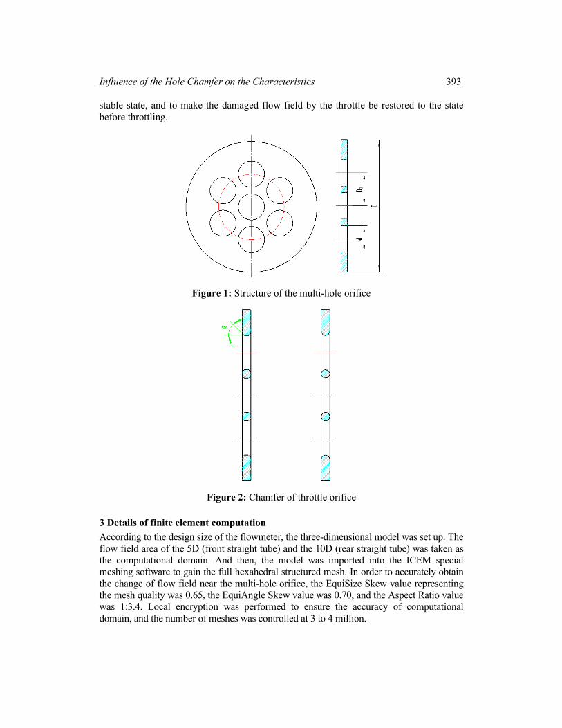
2 Structure of orifice In the literature [Hao, Song, Jia et al (2018)], the central symmetrically distributed 7-hole orifice flowmeter had better metering performance. Therefore, to study the effect of hole chamfer on the metering performance, a 7-hole orifice flowmeter was used as the research object, and its holes were chamfered or filleted. The orifice structure is shown in Fig. 1, where D=80 mm, d=13.6 mm, D1=40 mm. The condition of the holes is: symmetrical chamfering α=30°, 45°, 60° and symmetrical filleting treatment respectively, as shown in Fig. 2. Based on the design manual of flow measurement throttle, the geometric sizes of the flowmeter were established. The upstream and downstream parts of the flowmeter were designed with a certain straight pipe to ensure that the flow field is in a uniform and
Influence of the Hole Chamfer on the Characteristics 393
stable state, and to make the damaged flow field by the throttle be restored to the state before throttling.
Figure 1: Structure of the multi-hole orifice
Figure 2: Chamfer of throttle orifice
3 Details of finite element computation According to the design size of the flowmeter, the three-dimensional model was set up. The flow field area of the 5D (front straight tube) and the 10D (rear straight tube) was taken as the computational domain. And then, the model was imported into the ICEM special meshing software to gain the full hexahedral structured mesh. In order to accurately obtain the change of flow field near the multi-hole orifice, the EquiSize Skew value representing the mesh quality was 0.65, the EquiAngle Skew value was 0.70, and the Aspect Ratio value was 1:3.4. Local encryption was performed to ensure the accuracy of computational domain, and the number of meshes was controlled at 3 to 4 million.
394 FDMP, vol.15, no.4, pp.391-401, 2019
Because of the flow field complexity of multi-hole orifice flowmeter, the Standard k-ε turbulence model commonly used in engineering was adopted in the Fluent simulation. In the calculation, the entrance condition was the speed entrance (velocity-inlet), the exit was the free development flow (outflow). The coupling method of the speed and pressure was selected as SIMPLEC, with the residual difference of each parameter less than 0.00001 as the convergence standard. The flow field characteristics of the multi-hole orifice flowmeter were calculated under several inlet velocities such as 0.5, 1.0, 3.0, 7.0 m/s, respectively. The simulation calculation of the multi-hole orifice plate was described in detail in literature [Song, Jia, Yang et al. (2018)].
4 Flow field characteristics 4.1 Flow field distribution The simulation results are processed and analyzed to obtain the velocity distribution cloud maps, as shown in Figs. 3-6. By the velocity distribution cloud maps, it can be seen that after the medium passes through the orifice, a plurality of jets are formed. As inevitable results, a wall surface recirculation zone and a jet recirculation zone exist in the wake flow field, and various vortices such as a reflux vortex are present in the recirculation zone. The calculation results are consistent with the theory of double jet mechanics. The downstream velocity field of the multi-hole orifice has a clear convergence trend, and the upstream and downstream flow can quickly be resorted to the stable state.
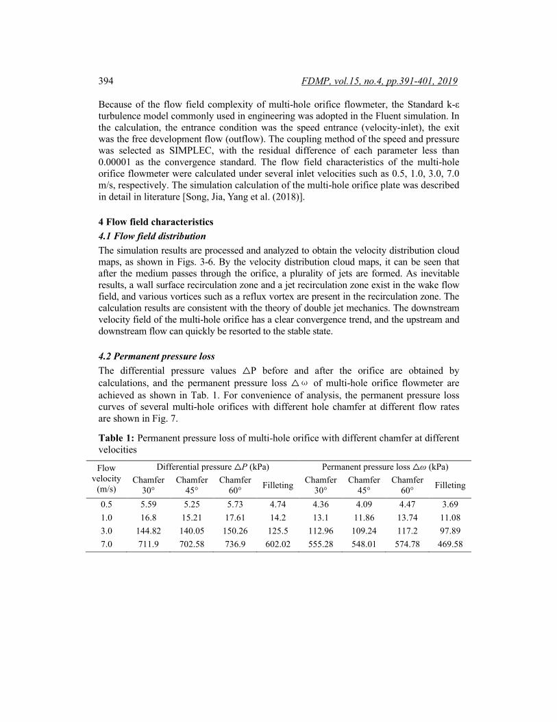
4.2 Permanent pressure loss The differential pressure values △P before and after the orifice are obtained by calculations, and the permanent pressure loss △ω of multi-hole orifice flowmeter are achieved as shown in Tab. 1. For convenience of analysis, the permanent pressure loss curves of several multi-hole orifices with different hole chamfer at different flow rates are shown in Fig. 7.
Table 1: Permanent pressure loss of multi-hole orifice with different chamfer at different velocities
Flow velocity
(m/s)
Differential pressure △P (kPa) Permanent pressure loss △ω (kPa) Chamfer
30° Chamfer
45° Chamfer
60° Filleting Chamfer 30°
Chamfer 45°
Chamfer 60° Filleting
0.5 5.59 5.25 5.73 4.74 4.36 4.09 4.47 3.69 1.0 16.8 15.21 17.61 14.2 13.1 11.86 13.74 11.08 3.0 144.82 140.05 150.26 125.5 112.96 109.24 117.2 97.89 7.0 711.9 702.58 736.9 602.02 555.28 548.01 574.78 469.58

Influence of the Hole Chamfer on the Characteristics 395
a) 0.5 m/s b) 1.0 m/s
c) 3.0 m/s d) 7.0 m/s
Figure 3: Velocity cloud map of orifice flowmeter with 30° chamfer

396 FDMP, vol.15, no.4, pp.391-401, 2019
a) 0.5 m/s b) 1.0 m/s
c) 3.0 m/s d) 7.0 m/s
Figure 4: Velocity cloud map of orifice flowmeter with 45° chamfer
Influence of the Hole Chamfer on the Characteristics 397
a) 0.5 m/s b) 1.0 m/s
c) 3.0 m/s d) 7.0 m/s
Figure 5: Velocity cloud map of orifice flowmeter with 60° chamfer

398 FDMP, vol.15, no.4, pp.391-401, 2019
a) 0.5 m/s b) 1.0 m/s
c) 3.0 m/s d) 7.0 m/s
Figure 6: Velocity cloud map of orifice flowmeter with filleting

Influence of the Hole Chamfer on the Characteristics 399
Figure 7: Permanent pressure loss curves vs. flow velocity
As can be seen from Tab. 1 and Fig. 7, the permanent pressure losses of multi-hole orifice flowmeter with chamfering transition around the throttle orifice are not prominently different. The permanent pressure loss of orifice flowmenter with chamfer 45° is slightly smaller and lower than that without chamfered orifice. Meanwhile, the permanent pressure loss of multi-hole orifice flowmeter with filleting is smaller than that with chamfering. Therefore, in the actual engineering design, the first consideration should be given to the transition of chamfering 45° or the direct filleting.
4.3 Outflow coefficient C According to the differential pressure value △P of the front and before orifice, the outflow coefficient C was calculated by the method in literature [Song, Jia, Yang et al. (2018)]. The outflow coefficient curves of several multi-hole orifices with different chamfer of holes at different flow rates are shown in Fig. 8. From the Fig. 8, whether at low or high flow rates, the outflow coefficient of multi-hole orifice flowmeter with filleting is higher than that with chamfering, and the stability is better. So, the multi-hole orifice flowmeter with filleting has a high metering accuracy over a wide range. At the same time, compared to the non-chamfered multi-hole orifice flowmeter, the multi-hole orifice flowmeter with chamfering has a higher outflow coefficient, and it can maintain good stability and has high measurement accuracy with the change of the flow rate.
400 FDMP, vol.15, no.4, pp.391-401, 2019
Figure 8: Outflow coefficient curve vs. flow velocity
5 Conclusions Taken the multi-hole orifice flowmeter with DN80 and throttle ratio of 0.45 as the research object, CFD simulation analysis were (was) carried out under different chamfer of holes. The conclusions are as follows: The symmetrical chamfer and fillet of the throttle hole are important factors affecting the permanent pressure loss, adjusting the wake flow field, improving the measurement accuracy and broadening the measurement range. The multi-hole orifice differential pressure flowmeter with fillet of the throttle hole has smaller permanent pressure loss value, higher outflow coefficient and better stability, and so has higher measurement accuracy in a wide range of measurement. Acknowledgement: The authors acknowledge the financial supports of Hebei province high-tech industry multiplier project (No. 16211702D) and Chengde science and technology & development project (No. 20152013).
References Cheng, Y.; Liu, Y. C. H. (2015): Research on function pore structure of porous orifice flowmeter. Instrumental Technique and Sensor, vol. 2, no. 3, pp. 23-25. Dong, M. Y.; Jing, C. J.; Peng, Y.; Liu, Y.; Ren, H. et al. (2018): Study on the measurement accuracy of an improved cemented carbide orifice flowmeter in natural gas pipeline. Flow Measurement & Instrumentation, vol. 59, no. 2, pp. 52-62. Hao, C. Z.; Song, X. M.; Jia, Z. N.; Yang, Y. (2018): Influence of hole number on flow field of multi-hole orifice flowmeter. Quarterly Journal of Indian Pulp and Paper Technical Association, vol. 30, no. 4, pp. 484-491. Medeiros, K. A. R.; Barbosa, C. R. H.; Oliveira, E. C. D. (2015): Flow measurement
Influence of the Hole Chamfer on the Characteristics 401
by piezoelectric accelerometers: application in the oil industry. Liquid Fuels Technology, vol. 33, no.13-14, pp. 81-84. Mia, B.; Srdjan, S.; Margaritis, K.; Lars, B.; Thomas J. R. P. (2010): Siginal-and two-phase numerical modes of dissolved ari flotation: comparison of 2d and 3d simulations. Colloids and Surfaces a: Physicochemical and Engineering Aspects, vol. 5, no. 365, pp. 139-141. Ma, T. Y.; Wang, D.; Zhang, B. D.; Lin, Z. H. (2010): Experimental study on flow measurement of multi-well plates. Nuclear Power Engineering, vol. 31, no. 2, pp. 126-130. Reader-Harris, M.; Barton, N.; Hodges, D. (2012): The effect of contaminated orifice plates on the discharge coefficient. Flow Measurement and Instrumentation, vol. 25, no. 3, pp. 3-5. Reader-Harris, M. J.; Sattary, J. A.; Spearman, E. P. (1995): The orifice plate discharge coefficient equation-further work. Flow Measurement and Instrumentation, vol. 6, no. 2, pp. 101-114. Sun, X. L. (2018): Strengthen the research of flow measurement methods, promote the steady development of energy measurement. Metrology and Testing Technology, vol. 45, no. 12, pp. 81-84. Shah, M. S.; Joshi, J. B.; Kalsi, A. S.; Prasad, C. S. R.; Shukla, D. S. (2012): Analysis of flow through an orifice meter: cfd simulation. Chemical Engineering Science, vol. 71 no. 2, pp. 300-306. Song, X. M.; Jia, Z. N.; Yang, Y.; Wang, Z. Q. (2018): A symmetrical multi-hole orifice pressure differential flowmeter. Journal of Electronic Measurement and Instrument, vol. 32, no. 6, pp. 33-38. Singh, R. K.; Singh, S. N.; Seshadri, V. (2010): Performance evaluation of orifice plate assemblies under non-standard conditions using cfd. Indian Journal of Engineering and Materials Science, vol. 17, no. 6, pp. 399-406. Wang, H.; Priestman, G. H.; Beck, S. B. M.; Boucher, R. F. (1996): Development of fluidic flowmeters for monitoring crude oil production. Flow Measurement and Instrumentation, vol. 7, no. 2, pp. 94-98. Yu, H. S.; Zhang, T.; Xu, W. D. (2015): Influence of orifice chamfering on the flow field characteristic of muti-hole orifice flowmeter. Journal of Electronic Measurement and Instrumentation, vol. 29, no. 9, pp. 1356-1364. Yu, H. S.; Zhang, T.; Zhao, S. S.; Jiang, W. (2014): Simulation of the flow field of multi-hole orifice flowmeter. Journal of Tianjin University (Science and Technology), vol. 47, no. 1, pp. 61-66. Zhao, T. Y.; Zhang, J. L. (2008): Experimental investigation of key parameters pertinent to multi-hole orifice throttling characteristic. Journal of Harbin Institute of Technology: New Series, vol. 15, no. 1, pp. 9-10.