Influence of membrane fouling on the removal of pharmaceutical
74
Faculty of Bioscience Engineering Academic year 2010 – 2012 Influence of membrane fouling on the removal of pharmaceutical Bui Thao Nguyen Promotor: Prof. dr. ir. Arne Verliefde Tutor: Oranso Themba Mahlangu Master‟s dissertation submitted in partial fulfillment of the requirements for the degree of Master in Environmental Sanitation
Transcript of Influence of membrane fouling on the removal of pharmaceutical

Faculty of Bioscience Engineering
Academic year 2010 – 2012
Influence of membrane fouling on the removal of
pharmaceutical
Bui Thao Nguyen
Promotor: Prof. dr. ir. Arne Verliefde
Tutor: Oranso Themba Mahlangu
Master‟s dissertation submitted in partial fulfillment of the requirements for the degree of
Master in Environmental Sanitation
Influence of membrane fouling on the removal of pharmaceutical
i
COPYRIGHT
„The author and the promoter authorize consultation and partial reproduction of this
thesis for personal use. Any other reproduction or use is subject to copyright protection.
Citation should clearly mention the reference of this work.‟
„De auteur en de promoter geven toelating deze thesis voor consultative beschikbaar te
stellen en delen ervan te kopieren voor persoonlijk gebruik. Elke ander gebruik valt
onder de beperkingen van het auteursrecht, in het bijzonder met betrekking tot de
verplichting de bron te vermelden bij het aanhalen van resultaten uit deze scriptie.‟
Gent, August 2012
The promoter The author
De promoter De auteur
Prof. Dr. ir. Arne Verliefde Bui Thao Nguyen

Influence of membrane fouling on the removal of pharmaceutical
ii
ACKNOWLEDGEMENTS
First and foremost, I would like to express my sincere gratitude to my promoter Prof. dr.
ir. Arne Verliefde for giving me an opportunity to work in the Laboratory of the
Department of Applied Analytical and Physical Chemistry. His good advices and support
have been invaluable on my academic achievement.
I would especially thank to my tutors, Oranso Themba Mahlangu and Arnout Dhaese
for their unreserved support and guidance during the whole thesis research.
I am deeply grateful to Prof. dr. ir. Paul Van der Meeren who gave background about
membrane through the course Membrane Technology in Environmental Treatment.
Thank Quenten Denon for repairing the pilot set-up and the TOC analyser. Especially,
all staffs in the lab have always created such a wonderful working environment and for
that, I thank all of them.
I am also grateful to the Prof. M. Van der Heede and Coordinators of Centre for
environmental Sanitation for assisting me in many different ways throughout the two
years of the master programme.
Last but not the least, I wish to thank my parents, little brother and two cousin who
have always supported, encouraged and believed in me. I dedicate this thesis to them.
Bui Thao Nguyen
August 2012

Influence of membrane fouling on the removal of pharmaceutical
iii
ABBRIVIATIONS
Abbriviation Description
NF Nanofiltration
MF Microfiltration
UF Ultrafiltration
RO Reverse Osmosis
CECP Cake enhanced concentration polarization
CP Concentration polarization
TMP The applied pressure
Δ𝜋 The osmosis pressure
MWCO Molecular weight cut off
SA Sodium alginate
SD Standard deviation
WWTP Wastewater treatment plant
DLS Dynamic light scattering
PCS Photon correlation spectroscopy
TOC Total organic carbon

Influence of membrane fouling on the removal of pharmaceutical
iv
TABLE OF CONTENTS
CHAPTER 1: INTRODUCTION .................................................................................................. 1
CHAPTER 2: LITERATURE REVIEW ........................................................................................ 3
2.1. MEMBRANE TECHNOLOGY ................................................................................................ 3
2.1.1. The growth of membrane technology ............................................................................... 3
2.1.2. Principles of membrane separation and classification ...................................................... 4
2.2. MEMBRANE FOULING ......................................................................................................... 6
2.2.1. The problems of membrane operation .............................................................................. 6
2.2.2. Concentration polarization and fouling ............................................................................. 7
2.3. MEMBRANE FOULING MECHANISMS ............................................................................. 11
2.3.1. Increased hydraulic resistance........................................................................................ 12
2.3.2. Cake-enhanced concentration polarisation ..................................................................... 12
2.4. ORGANIC SOLUTE REJECTION BY MEMBRANES ......................................................... 14
2.4.1 Conventional treatment over RO/NF membranes........................................................... 14
2.4.2 Organic solute rejection by NF/RO membranes ............................................................. 15
2.4.3 Qualitative rejection prediction of organic solutes ......................................................... 16
2.5. THEORETICAL BACKGROUND AND MEMBRANE TRANSPORT MODELS –
QUANTITATIVE REJECTION PREDICTION ...................................................................... 18
2.5.1. Membrane transport models ........................................................................................... 18
2.5.2. Determination of hindrance factors Kc and Kd ................................................................ 21
2.5.3. Determination of the solute partition coefficient ∅ ......................................................... 21
2.6. GOAL OF THIS THESIS ....................................................................................................... 22
CHAPTER 3: MATERIALS AND METHODS ........................................................................... 24
3.1. MEMBRANE FILTRATION SET UP AND EXPERIMENTAL PROTOCOL ....................... 24
3.1.1. Cross-flow filtration set-up and experimental protocol ................................................... 24
3.1.2. Dead-end filtration set-up and filtration protocol............................................................ 26
Influence of membrane fouling on the removal of pharmaceutical
v
3.2. CHEMICALS AND REAGENTS ........................................................................................... 27
3.2.1. Model foulants ............................................................................................................... 27
3.2.2. Model pharmaceutical .................................................................................................... 29
3.2.3. Other chemicals.............................................................................................................. 31
3.3. NANOFILTRATION MEMBRANE ....................................................................................... 32
3.3.1. Membrane properties ..................................................................................................... 32
CHAPTER 4: RESULTS AND DISCUSSION ........................................................................... 24
4.1. INFLUENCE OF MEMBRANE FOULING ON PERMEATE FLUX..................................... 35
4.1.1. Permeate flux of clean membrane ................................................................................. 35
4.1.2. Fouling by aluminum oxide ............................................................................................ 36
4.1.3. Fouling by latex.............................................................................................................. 37
4.1.4. Fouling by sodium alginate ............................................................................................ 39
4.1.5. Fouling by combined foulants......................................................................................... 41
4.2. EFFECTS OF MEMBRANE FOULING ON INORGANIC SALT REJECTION .................... 42
4.2.1. Salt rejection of clean membrane ................................................................................... 42
4.2.2. Salt rejection of fouled membranes ................................................................................ 43
4.3. REJECTION OF CARBAMAZEPINE ................................................................................... 46
4.3.1 Rejection of carbamazepine by clean membrane ........................................................... 46
4.3.2 Rejection of carbamazepine by fouled membranes ........................................................ 47
4.4. CARBAMAZEPINE-MEMBRANE AFFINITY ..................................................................... 50
CHAPTER 5: CONCLUSIONS AND RECOMMENDATIONS ................................................... 24
5.1. CONCLUSIONS .................................................................................................................... 53
5.2. RECOMMENDATIONS FOR FUTURE WORKS ................................................................. 54

Influence of membrane fouling on the removal of pharmaceutical
vi
LIST OF TABLES
Table 2.1: Overview of liquid pressure driven membrane processes ............................. 5
Table 3.1: Concentrations of foulants for experimental runs ........................................ 28
Table 3.2: Properties of Carbamazepine ...................................................................... 30
Table 3.3: Some properties of membrane given by manufacturer ................................ 32
Table 4.4: Surface tension components and the free-energy of intertactions
for clean and fouled membranes ................................................................ 50

Influence of membrane fouling on the removal of pharmaceutical
vii
LIST OF FIGURES
Figure 2.1: Schematic representation of a two-phase system separated by a
membrane ................................................................................................. 4
Figure 2.2: Flux behavior as a function of time ............................................................. 6
Figure 2.3: Concentration polarization profile under steady-state conditions ............... 8
Figure 2.4: Flux as a function of time for both concentration polarization and fouling 10
Figure 2.5: Overview of various types of resistances towards mass transport across a
membrane in pressure driven process ..................................................... 11
Figure 2.6: Flow chart for prediction of rejection of organics by high pressure
membranes .............................................................................................. 18
Figure 3.1: Nanofiltration set-up for rejection experiments with selected membranes 25
Figure 3.2: Filtration protocol for fouling/rejection experiments .................................. 26
Figure 4.1: Relative flux as a function of time for clean membrane ............................ 35
Figure 4.2: Relative flux as a function of time for fouling experiment with Al2O3 + CaCl2
................................................................................................................. 36
Figure 4.3: Relative flux as a function of time for latex fouling experiments with and
without CaCl2 ........................................................................................... 38
Figure 4.4: Relative flux as a function of time for SA fouling experiment with and without
CaCl2 ....................................................................................................... 40
Figure 4.5: The evolutions of permeate fluxes in combined fouling experiments
................................................................................................................. 41
Figure 4.6: Salt rejection for clean membrane as a function of time .............................. 43
Figure 4.7: The reduction of salt rejection of clean membrane and different fouled
membrane ................................................................................................ 44
Figure 4.8: Experimental values for carbamazepine rejection by the clean membrane
as a function of time ................................................................................. 47

Influence of membrane fouling on the removal of pharmaceutical
viii
Figure 4.9a: Carbamazepine rejection behavior of fouled membrane with the absence
of CaCl2 .................................................................................................... 47
Figure 4.9b: Carbamazepine rejection behavior of fouled membrane with the presence
of CaCl2 ................................................................................................... 48
Figure 4.9c: Carbamazepine rejection behavior of fouled membrane with combined
foulants .................................................................................................... 48
Figure 4.10: Comparison between the reduction of salt rejection and carbamazepine
rejection .................................................................................................... 49
Figure 4.11: The reductions of salt rejection and carbamazepine rejection vs.
interaction energy ..................................................................................... 52

Influence of membrane fouling on the removal of pharmaceutical
ix
ABSTRACT
The occurrence of pharmaceuticals in water bodies has become an increasing concern,
particularly due to possible problems related to human health effects. However, these
pollutants are not completely removed by conventional water treatment plants and even
state-of-the-art high pressure membrane filtration installations sometimes demonstrate
incomplete removal. Therefore, the aim of this study was to elucidate mechanisms
affecting pharmaceutical removal by high pressure membranes, and to evaluate the
impact of membrane fouling on this removal. The widely used pharmaceutical
carbamazepine was used as a model solute, and an NF 270 membrane was chosen as
representative membrane. Aluminum oxide, sodium alginate, latex and their
combinations were used as model foulants to simulate fouling in nanofiltration process.
These foulants were chosen to mimic foulants naturally present in surface water.
Filtration and fouling experiments were conducted in the presence and absence of
divalent cations, since these are known to aggravate membrane fouling. The
membranes and foulants were further characterized to elucidate the effects of (physico-
chemical properties of) the fouling layers on rejection of carbamazepine and salts. It was
observed that membrane fouling by latex resulted in a very severe flux decline, but the
effects on salt rejection and carbamazepine rejection were minor. Sodium alginate
fouling, on the other hand, resulted in less flux decline, but did cause significant
reductions in both salt and carbamazepine rejections. Cake-enhanced concentration
polarization was found to play a crucial role in the rejection of salts and carbamazepine.
Surprisingly, free energies of interaction between carbamazepine and the fouled
membranes did not correlate very well with the determined rejection. This is most likely
caused by the overwhelming effect of cake-enhanced concentration polarization.

Influence of membrane fouling on the removal of pharmaceutical
1
CHAPTER 1
INTRODUCTION
Recently, there has been an increasing concern about the emergence of trace organic
contaminants in the water resources worldwide. These pollutants include
pharmaceutically active compounds, endocrine disrupting compounds and personal care
products. They are present in municipal sewage, mainly as a result of improper human
disposal. In some cases, pesticides are also detected in drinking water resources due to
agricultural run-offs [1]. However, there is limited knowledge regarding health problems
associated with consumption of water contaminated with trace amounts of these
pollutants.
During the last decades, high pressure membrane processes such as nanofiltration (NF)
and reverse osmosis (RO) became widely employed mainly in new water treatment
systems. Currently, NF/RO membranes are mostly employed for the production of high
quality potable water which conventional treatment plants not using membranes cannot
produce. Although NF/RO are very promising for the removal of organics, traces of
some of the pollutants are still detected in the effluent of NF/RO membrane systems.
Moreover, it has been observed in many NF and RO plants that this incomplete rejection
efficiency can even be aggravated membrane fouling, which is an inevitable
phenomenon in full-scales applications. Many studies on membrane fouling have been
carried out [2-13] because the accumulation of foulants on the membrane surface result
in serious operational problems, such as a decline in permeate flux and a resulting
energy increase. However, less studies have clearly focused on the underlying
mechanisms of the effects of fouling on rejection of trace organic compounds. The latter
is a difficult research field, mainly due to the complexity of the mixtures and the
variability in the characteristics of organic compounds to be rejected, the foulants and
the membranes. Therefore, there is a need to further investigate the effect of membrane
fouling by different foulants (separately, but more interestingly when they co-exist in the
Influence of membrane fouling on the removal of pharmaceutical
2
same solution with others) on rejection of organic compounds. This is very important as
it generally represents the situation in real NF/RO applications.
Therefore, this dissertation was aimed at investigating the influence of membrane
fouling on the removal of the model pharmaceutical carbamazepine in surface water
applications. Three types of foulants were used to foul the membrane. One type of
organic foulants was used (sodium alginate, mimicking biopolymers in surface water),
and two types of inorganic foulants, mimicking colloids in surface water. Fouling
experiments were performed with each foulant existing solely in the feed water and also
in the presence of other foulants. The observed permeate flux and salt rejection as a
function of time were used to determined the magnitude of fouling. The membrane and
foulants characteristics were carefully determined, to see if a correlation could be found
between the physico-chemical characteristics of the foulants and the pharmaceuticals,
and the observed flux declines and changing rejection values.

Influence of membrane fouling on the removal of pharmaceutical
3
CHAPTER 2
LITERATURE REVIEW
2.1. MEMBRANE TECHNOLOGY
2.1.1. The growth of membrane technology
There has been a significant growth in development and application of membrane
technology in the last few decades. Currently membrane processes such as
microfiltration, nanofiltration, ultrafiltration and reverse osmosis are used in a wide range
of applications, in sectors such as food and beverages, metallurgy, pulp and paper,
textile, pharmaceutical, dairy, biotechnology and in the chemical industry [14]. This
increase in use is mainly due to the rise in environmental concerns about water quality
and scarcity, since membrane technology has been recognized as one of the
applications that could be used to provide safe water from impaired sources such as
seawater desalination, surface water treatment and reclamation of wastewater. This
makes potable water and wastewater treatment plants the largest markets for
membrane consumption, accounting for nearly half of the sales. Demand for membranes
globally has reached €13 billion yearly and 2012, and an average percent annual rise is
further expected. The BRIC countries (Brazil, Russia, India and China) and other
countries which are arranged as strongly developing industries and/or under stress of
water resources will see the fastest growth of membrane technology. In terms of
regional distribution, North America will occupy the largest membrane market. However,
the growth will be limited in many developing countries, particularly in Africa and parts of
South Asia, due to the still hefty capital investment costs that are required. The largest
investments in membrane technology for water treatment (mainly seawater desalination)
are currently found in the Middle East, to guarantee sufficient water supply for drinking,
agriculture and industries [15].

Influence of membrane fouling on the removal of pharmaceutical
4
2.1.2. Principles of membrane separation and classification
There are several types of membrane processes dependent on the driving force that is
used. In all processes, the membrane acts as a (semi-permeable) barrier between two
phases, and the membrane controls the passage of different chemical substances from
one phase to the other. The separation process is dependent on the characteristics of
both the chemical substances that need to be retained and the membrane.
A preferential passage of solvent molecules through the membrane, versus a dedicated
limited passage of solute molecules, leads to a reduction in concentration of that solute
in the produced water (the permeate) and an increase in the feed water if filtration is
carried in a full recirculation mode. Figure 2.1 shows a schematic representation of a
typical membrane separation process.
Figure 2.1: Schematic representation of a two-phase system separated by a
membrane
As can be seen in Figure 2.1, by application of a driving force to the components in the
feed side, transportation through the membrane takes place. The driving force can be a
chemical potential difference or an electrical potential difference as a result of
differences in either applied pressure, solute concentration, temperature,
∆𝑪,∆𝑷,∆𝑻,∆𝑬
Driving force
Feed Permeate
Phase 1 Membrane
Phase 2
Influence of membrane fouling on the removal of pharmaceutical
5
and/orelectrical potential between the different sides of the membrane. Pressure-driven
membrane processes are the most common in water treatment.
Pressure-driven membranesystems are classified based on several factors, including
the materials from which they are made, their physical configurations and pore sizes,
and the conditions under which the systemsare operated. The most used criteria in
pressure-driven membrane processes are the pore size and or the applied
transmembrane pressure. As such, pressure-driven membrane processes are grouped
into microfiltration (MF), ultrafiltration (UF), nanofiltration (NF) and reverse osmosis (RO)
membranes [14,16]. Table 2.1 presents an overview of these pressure driven membrane
processes.
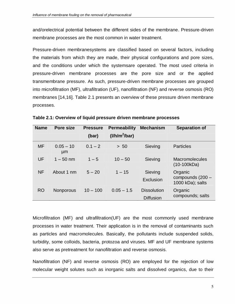
Table 2.1: Overview of liquid pressure driven membrane processes
Name Pore size Pressure
(bar)
Permeability
(l/h/m2/bar)
Mechanism Separation of
MF 0.05 – 10 µm
0.1 – 2 > 50 Sieving Particles
UF 1 – 50 nm 1 – 5 10 – 50 Sieving Macromolecules (10-100kDa)
NF About 1 nm 5 – 20 1 – 15 Sieving
Exclusion
Organic compounds (200 – 1000 kDa); salts
RO Nonporous 10 – 100 0.05 – 1.5 Dissolution
Diffusion
Organic compounds; salts
Microfiltration (MF) and ultrafiltration(UF) are the most commonly used membrane
processes in water treatment. Their application is in the removal of contaminants such
as particles and macromolecules. Basically, the pollutants include suspended solids,
turbidity, some colloids, bacteria, protozoa and viruses. MF and UF membrane systems
also serve as pretreatment for nanofiltration and reverse osmosis.
Nanofiltration (NF) and reverse osmosis (RO) are employed for the rejection of low
molecular weight solutes such as inorganic salts and dissolved organics, due to their

Influence of membrane fouling on the removal of pharmaceutical
6
small pore sizes. Due to their higher membrane resistance, a much higher pressure
must be applied to force the same amount of solvent through the membrane. NF and
RO are often considered as one process because they have the same basic principles
of separation (see further).
Although NF/RO membranes may serve as good candidates for the removal of organics,
unfortunately their operation can be greatly affected by membrane fouling which has
been reported to cause membranes performing poorly [2,48].
2.2. MEMBRANE FOULING
2.2.1. The problems of membrane operation
Membrane performance in terms of flux and solute removal (rejection) can change
significantly with time. A typical flux behaviour as a function of time is shown in Figure
2.2.
Figure2.2: Flux behavior as a function of time
Flux decline during seperation is one of the most crucial reasons why membrane
filtration processes are not more extensively used, since it results in increased pumping
costs, higher costs for membrane cleaning and thus has a negative influence on the
economics of a membrane [14].
Concentration polarization and membrane fouling are the main causes of membrane flux
decline. The former occurs directly and is reversible when flux is alleviated while the
later is long-term and irreversible. These two phenomena result from the nature of both
Flux
Time

Influence of membrane fouling on the removal of pharmaceutical
7
membrane and the feed, and by interactions between the membrane and the feed.
These phenomena are also dependent on other factors such as solute concentration,
particle size, pH and ionic strength of the feed, as well as the fluid shear forces [17].
2.2.2. Concentration polarization and fouling
2.2.2.1. Concentration polarization
In pressure-driven membrane applications, water is transported through the membrane
by an applied hydraulic pressure. However, as water is transported towards the
membrane, also the dissolved solutes are transported towards the membrane surface.
The solvent permeates through the membrane while the solutesare (partially) rejected
by the membrane. As a result, the rejected solute can accumulate at the membrane
surface, leading to a higher concentration of the solute at the membrane surface. Due to
this concentration build-up, there will be a driving force for diffusion of the solute away
from the membrane surface, back to the bulk of the feed (so-called back diffsion). This
back-diffusion is accelerated by a higher cross-flow velocity or a greater turbulence at
the membrane surface, since this increases mass transfer. After a short time of
operation,, a steady-state condition will be established whereby the convective solute
flow to the membrane surface exactly equals the diffusive solute flow away from the
membrane surface to the bulk (in some cases plus the solute flux through the membrane
if the membrane is not completely selective). In this steady-state mechanism, there will
still be a slightly higher concentration of solutes at the membrane surface compared to
the bulk. This phenomenon is called concentration polarization [14,17]. The
concentration profile that has been establish is schematically shown in Figure 2.3.

Influence of membrane fouling on the removal of pharmaceutical
8
Figure 2.3: Concentration polarization profile under steady-state conditions
The accumulation of solute within the concentration polarization (CP) layer can be
presented by the convection-diffusion equation:
𝐽 ∗ 𝐶 = 𝐽 ∗ 𝐶𝑝 − 𝐷 ∗𝑑𝐶
𝑑𝑦 (2.1)
where
- 𝐽: the solvent flux
- C : the solute concentration in the bulk
- Cp : the solute concentration in the permeat
- D : the diffusion coefficient
For spherical particles, the diffusion coefficient follows the Stokes-Einstein equation:
𝐷𝑜 =𝑘𝐵𝑇
3𝜋𝜇𝑑𝑝 (2.2)
where
- KB : the Boltzmann constant
- T : the absolute temperature
MEMBRANE
PERMEATE FEED
Boundary layer
Cb
Bulk concentration Cp
Permeate concentration
Permeate flux
J.Cp
Cm
Bulk feed
Convective
flow
Diffusive flow
Influence of membrane fouling on the removal of pharmaceutical
9
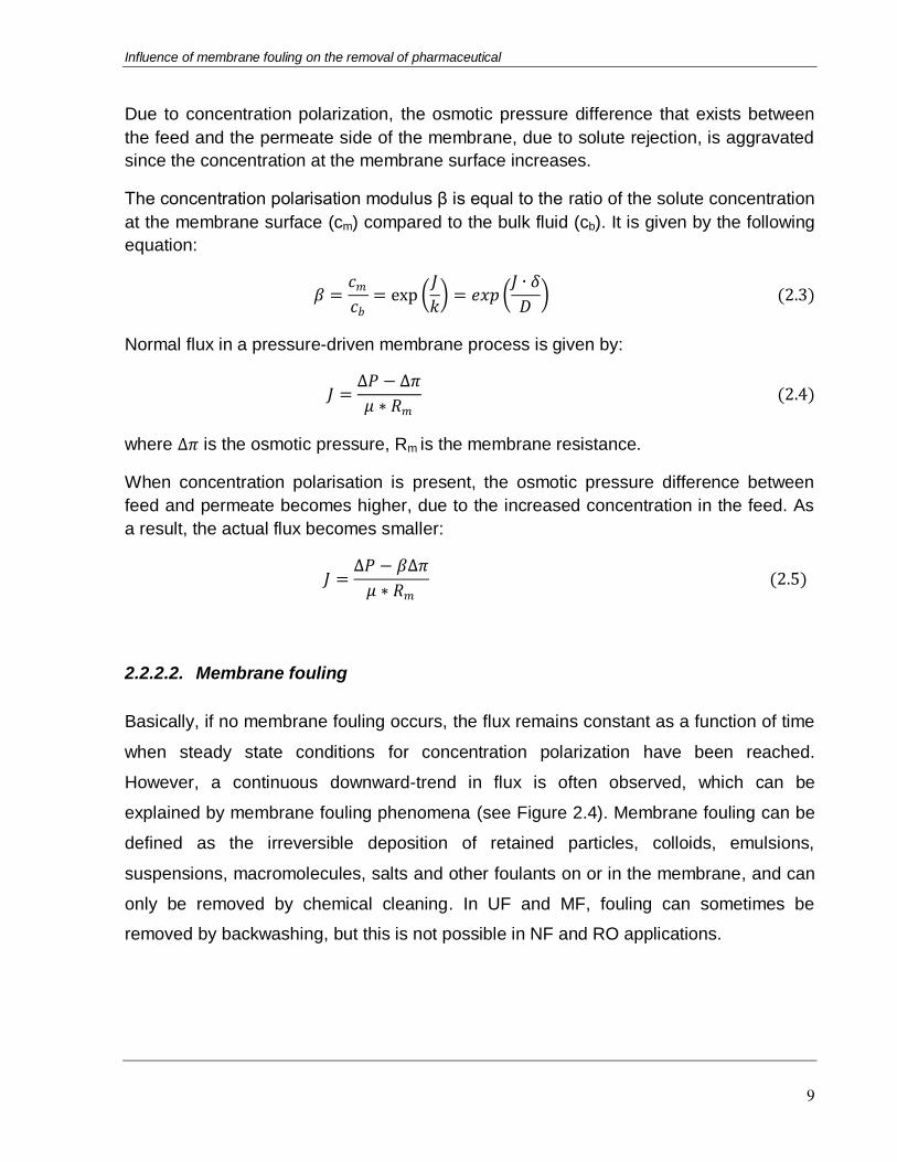
Due to concentration polarization, the osmotic pressure difference that exists between
the feed and the permeate side of the membrane, due to solute rejection, is aggravated
since the concentration at the membrane surface increases.
The concentration polarisation modulus β is equal to the ratio of the solute concentration
at the membrane surface (cm) compared to the bulk fluid (cb). It is given by the following
equation:
𝛽 =𝑐𝑚𝑐𝑏
= exp 𝐽
𝑘 = 𝑒𝑥𝑝
𝐽 ∙ 𝛿
𝐷 (2.3)
Normal flux in a pressure-driven membrane process is given by:
𝐽 =∆𝑃 − ∆𝜋
𝜇 ∗ 𝑅𝑚 (2.4)
where ∆𝜋 is the osmotic pressure, Rm is the membrane resistance.
When concentration polarisation is present, the osmotic pressure difference between
feed and permeate becomes higher, due to the increased concentration in the feed. As
a result, the actual flux becomes smaller:
𝐽 =∆𝑃 − 𝛽∆𝜋
𝜇 ∗ 𝑅𝑚 (2.5)
2.2.2.2. Membrane fouling
Basically, if no membrane fouling occurs, the flux remains constant as a function of time
when steady state conditions for concentration polarization have been reached.
However, a continuous downward-trend in flux is often observed, which can be
explained by membrane fouling phenomena (see Figure 2.4). Membrane fouling can be
defined as the irreversible deposition of retained particles, colloids, emulsions,
suspensions, macromolecules, salts and other foulants on or in the membrane, and can
only be removed by chemical cleaning. In UF and MF, fouling can sometimes be
removed by backwashing, but this is not possible in NF and RO applications.

Influence of membrane fouling on the removal of pharmaceutical
10
When the flux decline disappears by using pure water instead of the feed solution, the
flux decline is reversible and should not be considered as fouling, but is mainly the result
of concentration polarization [18]. Membrane fouling itself is not reversible when just
flushing with clean water. Membrane fouling includes adsorption, pore blocking, gel
layer formation and concentration polarization, which is described in the Figure 2.5.
In fact, fouling is basically an increase in membrane resistance due to the accumulation
on the membrane surface. Thus, the total resistance is constituted of all the above
resistances. In the ideal case where no fouling occurs, the only resistance is the
membrane resistance Rm. Through the filtration, however, the accumulation of solutes
near the membrane surface causes a highly concentrated layer near the membrane and
this layer forms a concentration polarization resistance. When the solute concentration
becomes too high, a gel layer can be formed and this refers to a gel layer resistance Rg.
Moreover, the solute particles can penetrate to the membrane pores and block these
pores which lead to a formation of pore-blocking resistance Rp. Finally, adsorption can
happen at the membrane surface and within the pore, Ra, and thus causes a rise in the
total resistance [14].
Figure 2.4: Flux as a function of time for both concentration
polarization and fouling
Flux
Concentration
polarization
Fouling Fouling
Time

Influence of membrane fouling on the removal of pharmaceutical
11
Figure 2.5: Overview of various types of resistances towards mass transport
across a membrane in pressure driven process.
2.3. MEMBRANE FOULING MECHANISMS
As mentioned above, fouling is a major problem influencing the operational performance
of the membrane, membrane stability and also energy cost. Despite many efforts to
reduce membrane fouling, for example, by improvement of membrane properties,
optimization of hydraulic conditions, and pretreatment of influent water, fouling is often
still inevitable. The phenomenon of fouling is very complex and difficult to describe.
Fouling depends on physical and chemical parameters, involving foulant concentration,
temperature, pH, ionic strength and specific interactions [14].
Fouling is mainly an accumulation of solids or dissolved solids on the membrane
surface. This can lead to an increased hydraulic resistance, which limits the driving force
Rcp
Porous
membrane Feed
Rp
Ra
Rm
Rg
Various resistances
- Rp : pore-blocking
- Ra : adsorption
- Rm : membrane
- Rg : gel layer formation
- Rcp : concentration
polarization

Influence of membrane fouling on the removal of pharmaceutical
12
that can actually be applied to drive water through the membrane. In addition, for NF
and RO membranes, flux decline can also be caused by another mechanism, the so-
called “cake-enhanced concentration polarization”.
2.3.1. Increased hydraulic resistance
The membrane resistance model can be employed to describe the permeate flow
through a membrane (see Equation 2.4). If the fouling layer only consists of equal-sized
spherical particles, the specific cake resistance (i.e. the resistance per unit cake
thickness) is usually predicted using the Carman-Kozeny equation:
𝑅𝑐 =180𝜇 1 − 휀𝑐
𝜌𝑝𝑑𝑝2휀𝑐3 2.6
where
- 휀𝑐 : the cake layer porosity
- 𝜌𝑝 : the solid density of the particle
- 𝑑𝑝 : the particle diameter
From this equation, it is predicted that a reduction in cake porosity and particle diameter
lead to a rise of the specific cake layer resistance. Of course, also as the thickness of
the cake increases, the membrane resistance will increase.
In practice, however, cake resistances are not that easy to calculate, since most cakes
do not only exist out of ideal spherical-shaped particles. Therefore, it is difficult to predict
the extra hydraulic resistance Rc due to fouling.
2.3.2. Cake-enhanced concentration polarisation
Since NF and RO are salt rejection membranes, there will always be an increase of salts
at the membrane surface (concentration polarization). This concentration polarization is

Influence of membrane fouling on the removal of pharmaceutical
13
usually kept under control by a cross-flow alongside the membrane, which creates back-
diffusion of salts to the bulk.
However, when NF and RO membranes get fouled by colloids and/or organic foulants,
the presence of these foulants can actually increase the concentration polarization of the
salts, since the back-diffusion of the salts is limited by the foulant cake on the membrane
surface. This increased concentration polarization results in an increase in osmotic
pressure difference across the membrane, and thus a decreased driving force for water
transport.
Mathematically, the increase in concentration polarization due to fouling, can be
represented by a change in the diffusion coefficient of the salts in the concentration
polarization model shown above. When there is a presence of a cake layer on the
membrane surface, the back-diffusion of smaller solutes (such as salts, which have a
high osmotic pressure) is hindered by the presence of the cake layer due to the tortuous
pathway of transport. This results in a hindered diffusion coefficient D* for back diffusion.
This hindered diffusion coefficient is related to the original diffusion coefficient, but also
to the porosity and the tortuosity of the cake layer and can be written as follows:
𝐷∗ =𝐷𝑜휀
𝜏2 (2.7)
The slower back diffusion due to the smaller diffusion coefficient (smaller porosity and
higher tortuosity lead to smaller diffusion) results in a faster accumulation of salts solutes
and therefore creates a higher concentration in the cake layer. This cake-enhanced
concentration polarization (CECP) is not only an important contributor to membrane flux
decline (mainly observed in colloidal fouling of NF and RO membranes), but is often also
accompanied by a drop of salt rejection over time (as a result of the concentration of salt
at the membrane surface going up).
Cake-enhanced concentration polarization, however, is not only limited to salts: with
dissolved organic compounds which are small enough and able to penetrate the
(colloidal) cake layer, CECP may also happen. As a consequence, the concentration of

Influence of membrane fouling on the removal of pharmaceutical
14
organic solutes such as pharmaceuticals in the cake layer can also increase, leading to
lower rejection values (see below) [3].
2.4. ORGANIC SOLUTE REJECTION BY MEMBRANES
Since membranes are often used for production of water from impaired water sources,
and impaired water sources are often polluted by trace organic chemicals such as
pesticides, pharmaceuticals, etc., it is important that these organic solutes are well
removed by the membranes
2.4.1 Conventional treatment over RO/NF membranes
Pharmaceuticals are developed to enhanced human health, but recently they have
become one of the notorious water pollutants [1,19]. A wide range of drug brands such
as antibiotics, anti-depressants, tranquillizers, cancer treatment pills and pain killers
have been detected in different water bodies at high concentrations [20]. Main sources
of these pollutants are hospitals, pharmaceutical industries and medical facilities as well
as households which dispose solutions of these contaminants directly into the drain
without treatment. Due to their polarity, persistence and water solubility, they are able to
pass through waste water treatment plants (WWTP). Their low adsorption on sludge and
soil may cause contamination of surface and ground waters. Although it is argued that
pharmaceuticals are not a problem to human beings due to their very low
concentrations, it is believed that long-term exposure to pharmaceuticals and similar
compounds is likely to interfere with hormone production. Moreover, the life of aquatic
flora and fauna are at great risk. As an evidence of this, anti-depressants have been
blamed for altering sperm levels and spawning patterns in marine life. Therefore, many
studies of pharmaceuticals in water mainly focus on aquatic animals [21].
In conventional wastewater treatment plants, the removal of antibiotics fluctuates
greatly. Nevertheless, several organic compounds are removed by some activated
sludge treatment processes via hydrolysis, biotransformation or sorption onto flocs,
suspended solid or activated sludge and then separated by sedimentation [22,23]. The

Influence of membrane fouling on the removal of pharmaceutical
15
removal efficiency of pharmaceutical pollutants is also influenced by the operating
conditions of the treatment process, such as temperature, hydraulic retention time (HTR)
and particularly solid retention time (STR). Due to high health risks associated with
ingestion of pharmaceuticals, there is a need to remove them in source water before it is
consumed by some of the removal processes (both advanced and tertiary) including
tertiary media filtration, ozonation, chlorination, UV radiation, activated carbon
adsorption and NF/RO filtration. Sand filtration and UV disinfection are less efficient in
removing almost all antibiotics. However, NF and RO membrane filtration processes are
much more effective in rejecting pharmaceuticals under optimal operation.
2.4.2 Organic solute rejection by NF/RO membranes
Organic solute rejection by membranes is dependent on a number of things, such as
hydrodynamic effects, concentration, pH and background electrolyte. However, the most
important factor is the solute-membrane interactions at the membrane interface. Indeed,
solute-membrane interactions are the key factors to determine the rejection of organic
solutes by membrane. These interactions include steric hindrance, solute-membrane
non-electrostatic affinity (often mistakenly referred to as hydrophobic interactions) and
electrostatic interactions. These solute-membrane interactions are mainly dependent on
solute and membrane physico-chemical properties, although process conditions and
feed water composition may play a role as well [4,24].
The first solute-membrane interaction is steric hindrance which is primarily a sieving
mechanism, and is thus mainly determined by membrane pore size and solute size:
solutes with a size larger than the membrane pore size are efficiently rejected, whereas
solutes with a smaller size can easily pass through the membrane. This mechanism
results in a typical sigmoidal (S-shaped) curve when rejection is plotted as a function of
the solute size or solute molar mass. This S-shape (instead of a step-curve) results from
the fact that the membrane has a certain pore size distribution around the average pore
size [25].

Influence of membrane fouling on the removal of pharmaceutical
16
Solute-membrane non-electrostatic affinity interactions typically include hydrophobic
attraction, hydrogen bonding and dielectric effects which are mainly determined by
solute and membrane physicochemical parameters. These interactions might have an
influence on the rejection, in addition to the steric hindrance. Solutes with high affinity to
membrane will be able to partition into the membrane matrix and diffuse through the
membrane, and finally leads to a lower rejection values. From a study conducted by
Verliefde et al [26], they demonstrated that there is a dramatic influence of solute-
membrane affinity on organic rejection by NF and RO membranes.
The third factor that also plays a crucial role in the rejection of organic solutes is
electrostatic interactions. Electrostatic interactions occur between charged solutes and
charged functional groups of the membranes. On the membrane surface, functional
groups may be carboxyl groups, amine groups and many others. In practice, most NF
and RO membranes are negatively charged due to the overwhelming presence of
carboxylic acid functional groups.
2.4.3 Qualitative rejection prediction of organic solutes
In order to predict the rejection of a solute by NF or RO membranes, it is essential to
know the contributions of the different physico-chemical interaction mechanisms.
Therefore, a number of physical/chemical properties of solute and membrane as well as
solution chemistry have to be carefully considered. These physic-chemical properties
include molecular size, charge, hydrophobicity of the solute, pore size, membrane
morphology, membrane and solute charge and membrane hydrophobicity.
Bellona et al. (2004) developed a simple flow chat (see Figure 2.6) that can be
qualitatively used to predict rejection of organics by high pressure membranes [28]. By
using the flow chart, one can initially estimate the rejection efficiency of NF/RO for non-
charged and negatively charged organic solutes. The organic compounds are classified
based on different physico-chemical characteristics including charge (based on the acid
constant)), hydrophobicity (expressed as the logarithm of the octanol-water partitioning
coefficient) and molecular size, in order to identify the main mechanisms responsible for

Influence of membrane fouling on the removal of pharmaceutical
17
rejection. Based on this diagram (which is based on a wide experimental database), the
dominant mechanisms of rejection can be determined and the rejection qualitatively
estimated when the physico-chemical characteristics of the solute and membrane are
known. The diagram is followed from the top to the bottom and incorporates the effect of
different physico-chemical characteristics of solute and membrane and also operating
conditions, for example the pH of feed water (since this determines the charge
properties). The general rejection prediction is given in qualitative terms of high,
moderate or low rejection; determined after passing through several levels of parameter
decisions.
Although this diagram is the useful tool for qualitative prediction of organic compounds
by membrane filtration, there are some limitations in its applicability for predicting
chemical behavior in real – full scale treatment system. Firstly, it is mainly used for a
qualitative estimation, while a quantitative estimation which is an extremely important
aspect of rejection is not involved. A further limitation of the membrane diagram is that it
only accounts for increased rejections due to electrostatic repulsion between the
negatively charged solutes and negatively charged membranes. In a study performed on
negatively charged membranes by Verliefde et al. [26], it was concluded that
electrostatic attractive forces may also occur between positively charged solutes and the
negatively charged membrane surface. These attractions result in the accumulation of
the positively charged solutes at the membrane surface and create an extra
concentration-polarization effect, leading to lower rejections of the positively charged
solutes.. Another drawback is that log Kow, as a descriptor of solute hydrophobicity, is
used to determine affinity interactions of the solute with the membrane. This is a serious
flaw, since log Kow only takes hydrophobic interactions into account. A final drawback of
the qualitative model, is that it does not take effects of membrane fouling into account.

Influence of membrane fouling on the removal of pharmaceutical
18
Figure 2.6: Flow chart for prediction of rejection of organics by high pressure
membranes
2.5. THEORETICAL BACKGROUND AND MEMBRANE TRANSPORT MODELS –
QUANTITATIVE REJECTION PREDICTION
2.5.1. Membrane transport models
To cope with the limitations of the qualitative rejection graph of Bellona et al., more
quantitative rejection models were developed over time. In the recent years, consensus
has been reached on the fact that transport through NF/RO membranes can be best
described by convection-diffusion models for pore transport. The most comprehensive
transport model for solutes through high-pressure membranes is the extended Nernst-
Planck equation, which gives the basic description of the transport of ions and organic

Influence of membrane fouling on the removal of pharmaceutical
19
solutes through the membranes (in fact the membrane pores). The equation is written as
(2.8):
𝐽𝑠 = −𝐷𝑝𝑑𝑐
𝑑𝑥−
𝑧𝑐𝐷𝑝
𝑅𝑇𝐹𝑑𝑣
𝑑𝑥+
𝐽𝑣
휀𝐾𝑐𝑐 (2.8)
Where
- Js and Jv : respectively the solute and solvent flux,
- ε : the membrane porosity
- Dp = KdD∞ : the solute diffusion coefficient in the membrane
- D∞ : the solute diffusion coefficient in water
- c : the solute concentration
- x : the axial position within the membrane
- Kc : the hindrance factor against convection transport
- Kd : the hindrance factor against diffusive transport
- z : valence of ion
- R : gas constant
- T : absolute temperature (oK)
- F : Faraday constant (Cmol-1)
The terms on the right hand side represent solute transport due to diffusion, the electric
field gradient and convection respectively.
For uncharged (organic) solutes, the effects of the electric field gradient can be
neglected. In these cases, the solute flux equation simplifies to the well-known Spiegler-
Kedem model, which states that transport of uncharged solute through nanofiltration and
reverse osmosis membranes can be presented by irreversible thermodynamics by a
combination of diffusive and convective transport [16,29] :
𝐽𝑠 = 𝑉 𝐶𝑝 = −𝐷𝑝𝑑𝑐
𝑑𝑥+
𝐽𝑣
휀𝐾𝑐 (2.9)
where 𝑉 is the average fluid velocity in pores ( 𝑉 =𝐽𝑣
휀) and Cp is the solute bulk
permeate concentration.

Influence of membrane fouling on the removal of pharmaceutical
20
In order to obtain an expression for solute rejection, Equation 2.9 needs to be integrated
with the following boundary conditions, which use the solute partition coefficient ∅. The
solute partition coefficient is the ratio of the solute concentration inside the membrane
pore over the solute concentration in the feed, so it describes whether a solute will easily
penetrate into the membrane or not. As such, it is probably the most important
parameter determining solute rejection.
Thus,
x = 0 (within the membrane at feed side):
cx=0 = cf = ∅Cm= ∅βCf (2.10)
x = Δx ( within the membrane at lower surface):
cx=Δx = cp = ∅Cp (2.11)
where
- Δx: the membrane thickness
- β : the hydrodynamic concentration polarization
- cf: the solute concentration in the membrane matrix at the feed side
- cp: the solute concentration in the membrane matrix at the permeate side
- Cf : the solute feed concentration in the bulk
- Cp: the solute permeate concentration in the bulk
- Cm : the solute feed concentration at the membrane surface
After integration, equation 2.9 becomes:
𝑅 = 1 −𝐶𝑝𝐶𝑓
= 1 −𝛽∅𝐾𝑐
1 − 1 − ∅𝐾𝑐 exp(−𝑃𝑒) (2.12)
where the Peclet number, 𝑃𝑒 is defined as:
𝑃𝑒 = 𝐽𝑣𝐾𝑑∆𝑥
𝐾𝑑휀𝐷∞ (2.13)
Equation (2.12) can be used to predict solute rejection by clean NF and RO membranes,
given that the values of all constants in the equation are known.

Influence of membrane fouling on the removal of pharmaceutical
21
2.5.2. Determination of hindrance factors Kc and Kd
In this study, the membrane is assumed to be porous with uniformed pores. If the solute
velocity profile is fully developed inside the membrane pores with a parabolic Hagen-
Poisseuille profile, these hindrance factors for convection and diffusion can be
calculated as [16]:
Kc = (2 - (1 – λ)2) (1 + 0.054λ – 0.988λ2 + 0.441λ3) (2.14)
Kd = 1 – 2.3λ + 1.154λ2 + 0.224λ3 (2.15)
Where λ = rs/rp which is the ratio of solute to pore radius.
2.5.3. Determination of the solute partition coefficient ∅
The solute partitioning coefficient is given by the following equation:
∅ = (1 − 𝜆)2 exp −∆𝐺𝑖𝑘𝑇
(2.16)
Where k is the Boltzmann constant, T is the absolute temperature (in oK) and ΔGi is the
free-energy difference associated with the differences in interactions of the solute in the
water phase and the membrane phase. The partition coefficient therefore depends on
ΔGi and the steric hindrance (expressed by the factor (1-λ)2. ΔGi can be used as a
quantification of attractive or repulsive solute-membrane affinity interactions. If ΔGi is
negative, transport of the solute to the membrane will be facilitated since the solute has
a high affinity for the membrane; when ΔGi is positive, the solute will be repulled by the
membrane and partitioning will be less. Only when ΔGi = 0,the traditional models which
only consider the size exclusion effects apply. It is clear that ΔG i thus has a large
influence on rejection. When there is less partitioning, rejection is higher.
ΔGi can be calculated based on the surface tensions of the solute (S), membrane (M)
and liquid (L):

Influence of membrane fouling on the removal of pharmaceutical
22
∆𝐺𝑖 = 𝐴∆𝐺𝑆𝐿𝑀
= 2
𝛾𝑆
𝐿𝑊𝛾𝐿𝐿𝑊 + 𝛾𝑀
𝐿𝑊𝛾𝐿𝐿𝑊 − 𝛾𝑠
𝐿𝑊𝛾𝑀𝐿𝑊 − 𝛾𝐿
𝐿𝑊
+ 𝛾𝐿+ 𝛾𝑆
− + 𝛾𝑀− + 𝛾𝐿
− − 𝛾𝑠+𝛾𝑀
− + 𝛾𝐿−( 𝛾𝑆
+ + 𝛾𝑀+ − 𝛾𝐿
+) − 𝛾𝑠−𝛾𝑀+
(2.17)
In which 𝛾𝑖𝐿𝑊 is the apolar (Lifshitz-van der Waals) component of the surface tension,
𝛾𝑖+and 𝛾𝑖
− are the electron – acceptor and electron – donor component of surface
tension, respectively. If water is used as a solvent, the values for 𝛾𝐿𝐿𝑊 , 𝛾𝐿
+ and 𝛾𝐿− are
known from literature. The remaining surface tension components for the membrane and
the solute can be calculated by contact angle measurements via the Dupré Young
equation:
1 + 𝑐𝑜𝑠𝜃 𝛾𝐿 = 2 𝛾𝑀𝐿𝑊𝛾𝐿
𝐿𝑊 + 𝛾𝑀+𝛾𝐿
− + 𝛾𝑀−𝛾𝐿
+ (2.18)
Where θ is the contact angle measured between a droplet of liquid L on the membrane
surface. By repetition of contact angle measurements with 3 different liquids with known
surface tension components and then solving the set of 3 equations, the surface tension
components of the membrane and compressed plates of solutes can be determined.
2.6. GOAL OF THIS THESIS
The objective of this thesis research is investigate the influence of fouling on the
removal of carbamazepine by the nanofiltration membrane process. Carbamazepine is
chosen as model pharmaceutical because it is one of pharmaceuticals that have the
highest concentration appearing in European surface waters [30]. Three model foulants
(aluminum oxide, latex and sodium alginate) are used. Aluminum oxide and latex are
model substitutes for inorganic colloids found in surface and waste water, whereas
sodium alginate acts as a model for biopolymers found in these water types. Aluminum
oxide and latex have different charge properties (the former positively charge, the latter
negative), to elucidate if charge effects play a role in membrane fouling and the

Influence of membrane fouling on the removal of pharmaceutical
23
influence on rejection. The membranes are fouled by these substituents separately, and
also by mixtures of these foulants. Fouling is monitored by the temporal changes of flux
and salt rejection. By spiking carbamazepine during the fouling runs, the influence of
fouling on carbamazepine rejection is also determined.
To investigate if the surface energy approach developed to model rejection for clean
membranes (see Equations (2.17) to (2.18) is also valid for fouled membranes, the
interaction energies between carbamazepine and the fouled membranes will be
determined and related to rejection behavior.
This study is mainly conducted on a small laboratory scale set-up with flat sheet
membrane coupons in a cross-flow mode. In addition, dead-end experiments are also
carried out to obtain smooth fouling layers for easier characterization of the membrane
surface properties.

Influence of membrane fouling on the removal of pharmaceutical
24
CHAPTER 3
MATERIALS AND METHODS
3.1. MEMBRANE FILTRATION SET UP AND EXPERIMENTAL PROTOCOL
3.1.1. Cross-flow filtration set-up and experimental protocol
3.1.1.1. Set-up
A laboratory-scale cross-flow reverse osmosis set-up was used in this study (Figure
3.1). The pilot RO installation (Boerenbond, Agro-Industries, Leuven, Belgium) consists
of a cylindrical membrane cell in which the membranes are packed in circular plate-and-
frame modules, in a sandwich like structure. The total effective surface area of the
membrane is 0.04 m2. For each fouling experiment, a new membrane piece was used to
eliminate the influence of the previous experiments.
The feed solution is delivered to the cell from a reservoir (10L) by a piston pump. The
concentrate flow rate was monitored by a rotameter. The feed pressure and cross-flow
velocity were controlled by means of a bypass valve and back pressure regulator. The
feed water temperature was kept constant (25 ± 2 OC) using a temperature controller
equipped with a stainless steel heater exchanger coil, which was submerged directly to
the feed reservoir. The concentrate and permeate fluxes were recycled back to the feed.
The permeate, was collected in a volumetric flask and timed to measure permeate flux.

Influence of membrane fouling on the removal of pharmaceutical
25
Figure 3.1: Nanofiltration set-up for rejection experiments with selected
membranes
3.1.1.2. Filtration protocol
Membrane fouling and subsequent retention experiments were conducted in two steps:
a first compaction step, followed by the actual and fouling run and rejection
measurement. A schematic of the filtration protocol depicts in Figure 3.2. Firstly, the
membrane was compacted using Milli-Q water at 8 bars in 2 hours or until the flux
stabilized. The In the next stage, a mixed solution containing electrolyte (10 mM NaCl),
carbamazepine (10 mg/l) and foulants were introduced to the feed reservoir and the
cross-flow velocity was adjusted to 0.2 m/s and the pressure was fixed at 3bars
(300kPa).

Influence of membrane fouling on the removal of pharmaceutical
26
Figure 3.2: Filtration protocol for fouling/rejection experiments
In these experiments, the fouling layer on the membrane surface was developed during
the filtration experiments which mean that the foulants and pharmaceutical were dosed
homogenously at the start. This is the situation which is the most representative for
practical membrane operation. Foulants were at first added separately to access single
foulant effect. They were then dosed in different combinations to evaluate the effect of
combined fouling on the permeate flux, the rejection of salt and the pharmaceutical
(carbamazepine). The experiment was run for 74h and the pH of the feed solution
(approximately 7.0) was adjusted.
The permeate samples were collected in glass vials with stoppers and stored in the 4oC
refrigerator before analysis of carbamazepine as total organic carbon.
3.1.2. Dead-end filtration set-up and filtration protocol
Due to the specific structure of the plastic frames used for the cross-flow mode, and due
to the washing off by the cross-flow velocity, fouled membranes from the cross-flow unit
Compaction: Milli-Q water
2 hours
Fouling run: Milli-Q water + Carbamazepine+ foulants
74 hours
Flux
Time

Influence of membrane fouling on the removal of pharmaceutical
27
had a non-uniform distribution of the cake layer. Therefore, it was difficult to characterize
this cake by characteristic analyses, including contact angle and streaming potential
measurements. To solve this problem, dead-end experiments were carried out on lab-
scale, to achieve denser and more uniform fouling layers. A membrane of a required
diameter of 51mm was cut and placed at the bottom of the unit. After sealing the unit, it
was pressured up to 10 bar using N2.
The filtration was run for 4 hour period, which allowed a thick layer of foulants
accumulated on the membrane. The fouled membranes were then removed from this
filtration system and then put on a desiccator in 24 hours. Contact angle measurements
were performed to determine surface properties of the fouled membranes and then
calculate the free energy of interactions between the solute and membranes.
3.2. CHEMICALS AND REAGENTS
3.2.1. Model foulants
Latex, Sodium Alginate and Aluminum oxide were used as model foulants in the
following experiments.
Latex is a liquid which extracted by some plants or trees, particularly rubber trees. It is
being used in many different applications such as adhesives, inks, paints, coating, drug
delivery systems, floor polish, films, carpet packing and so on [31]. Colloidal Latex was
obtained from EOC group, Industrial park, B9700 Oudenaarde. It was supplied at 50%
suspension in water and was successively stored in a refrigerator at 4oC.
Sodium alginate was supplied by Sigma – Aldrich (Product of United Kingdom).It was
originally extracted from brown algae. Sodium alginate (SA) was employed as a model
constituent of polysaccharide, one of the most ubiquitous constituents of extracellular
polymeric substances (EPS) in the secondary wastewater effluent. Its molecular weight
reported by the manufacturer is 10 – 60 kDa or 8291 g/mol.

Influence of membrane fouling on the removal of pharmaceutical
28
Commercial aluminum oxide Al2O3 colloids were employed as model colloids in the
fouling experiments. It was provided as 30% suspension by Evonik Degussa GmbH
(Hanau-Wolfgang, Belgium) with pH value of 3.0 – 5.0 and the density of 1.26 g/m3.
In order to investigate the effects of the selected foulants in the presence of divalent
ions, calcium chloride (CaCl2) was added to the feed solution. Table 3.1 summarizes
foulants chemistry used for the fouling experiments in this study.
Table 3.1: Concentrations of foulants for experimental runs
Fouling experiments Concentration (mg/l)
Al2O3 SA Latex CaCl2
Al2O3 30 - - -
Al2O3 + CaCl2 30 - - 2
SA - 20 - -
SA + CaCl2 - 20 - 2
Latex - - 30 -
Latex + CaCl2 - - 30 2
Al2O3 + SA + CaCl2 30 20 - 2
Latex +SA + CaCl2 - 20 30 2
3.2.1.1. Zeta potential measurements of the foulants
The value of the zeta potential describes the potential stability of the colloidal system. If
particles in suspension have a large negative or positive zeta potential, they will tend to
repel each other and no flocculation occurs. These particles are said to be stable. The
dividing line between stable and unstable suspension is generally put at either +30mV or
-30mV [11].
The zeta-potential of the individual colloids and the alginate molecules as function of pH
were measured by a Zetasizer2C (Malvern Instruments, United Kingdom). The particles
and molecules were suspended in electrolyte (10 mM of KCl), prepared with deionized
water. The electrolyte‟s pH was adjusted with either hydrochloric acid or sodium
hydroxide.

Influence of membrane fouling on the removal of pharmaceutical
29
The Zetasizer determines the electrophoretic mobility of particles in a solution. The
electrophoretic mobility refers to a velocity of a particle in an electric field. Zeta potential
was calculated from measured electrophoretic mobility by using the Helmholtz-
Smoluchowski Equation 3.1:
𝑈𝐸 =2휀𝑧𝑓 (𝑘𝑎 )
3𝜂 (3.1)
Where z is zeta potential, UE is electrophoretic mobility, ε and η are dielectric constant
and viscosity respectively, and f(ka) is the Henry‟s function.
3.2.1.2. Particle size measurements of the foulants
Particles were measured by the photon correlation spectroscopy (PCS 100M, Zetasizer
2C, Malvern Instruments, England). The measurement is based on laser light scattering.
Particles in a light beam will scatter light into space, with angles and intensities which
depend on the particle size, the optical properties of these particles, the light source and
their suspending medium. The Zetasizer 2C has a resolution between 0.05 μm and 3.5
mm.
3.2.2. Model pharmaceutical
Carbamazepine was chosen in this study as a model pharmaceutical.C15H12N2O is the
formula of carbamazepine and its molecular weight is 236.28 g/mol [10,32].
Carbamazepine is a widely used anti-epileptic drug and considered as a representative
pharmaceutically active compound. It is often found at trace levels in many different
water resources [34].In practice, this pharmaceutical can be quite persistent to the
conventional biological sewage treatment process [22]. However it be removed
effectively by nanofiltration or reverse osmosis filtration. Moreover, carbamazepine is

Influence of membrane fouling on the removal of pharmaceutical
30
also representative of the emerging trace organic contaminants commonly encountered
in secondary treatment effluent and sewage treatment [35].
A stock solution of carbamazepine (1 g/l) was prepared in Milli-Q water, stored at 4oC
and used within 1 month. In this study, carbamazepine was used at a concentration of
10 mg/l for all experiments. The purity of this chemical was reported to be 90% or
higher. Some typical properties of carbamazepine are given in the Table 3.2.
Table 3.2: Properties of Carbamazepine
Properties of Carbamazepine Carbamazepine
Solubility, mg/l 121
pKa 13.9
Log Kow 2.45
Charge at pH 7 Neutral
Molecular weight, g/mol 236.28
Molecular width1, nm 0.507
Molecular height1, nm 0.529
Molecular length1, nm 0.891
Molecular structure
1 Reference source: [10]
In order to evaluate the rejection of the non-ionzable pharmaceutical carbamazepine by
clean and fouled membranes, the TOC concentration of carbamazepine in permeate
samples were measured during the experimental runs. Since the degradation or
volatilization of carbamazepine did not occur in the relatively long period of experiments
(74 hours), the feed concentration was assumed to be constant throughout the
experiments. TOC measurements were conducted in 24 hours after samples were
collected.

Influence of membrane fouling on the removal of pharmaceutical
31
Carbamazepine concentration was measured as TOC using a Total organic carbon
(TOC) analyzer (Shimadzu TOC-VCSH, Shimadzu Scientific Instruments, USA). The
TOC analyser was calibrated for TC and IC using concentrations of 100 ppm TC and 20
ppm IC. Feed and permeate samples were analysed for TOC and rejection was
calculated using Equation 3.2.
𝑅𝑖 = 1 − 𝑐𝑝 ,𝑖
𝑐𝑓 ,𝑖 (3.2)
Where i is the solute of interest, and Ri, cp,I, and cf,I are the rejection, the permeate and
feed concentrations of solute i respectively. All samples were analyzed immediately after
the collection of the last sample.
To make sure that carbamazepine was the only compound responsible for TOC in the
permeate, blank experiments without addition of carbamazepine were carried out, which
showed negligible TOC in the permeate. This indicates that the rejection of sodium
alginate and other foulants is 100%, which was also expected based on their size
compared to the membrane pore size.
3.2.3. Other chemicals
Sodium chloride (supplied by VWR International bvba/sprl) was used to prepare the
background electrolytes for the feed solutions. Calcium chloride (supplied by Merck
Eurolab nv/sa) was employed to investigate the influence on the fouling rate of selected
foulants. These chemicals were dosed at 10 mM and 2 mg/l respectively.
Salt concentrations (sodium chloride) in the feed and permeate were measured using a
conductivity meter (Consort K612, Belgium). Salt rejection was also calculated by
Equation 3.1 with cp,I, and cf,I being conductivity of permeate and feed respectively. In
the concentration region used (10 mM of NaCl), salt concentration is linearly to
conductivity. Therefore, conductivity of the feed and permeate water were measured to
calculate salt rejection following previous research works [36].

Influence of membrane fouling on the removal of pharmaceutical
32
All solutions and feed water were prepared with Milli-Q water which had conductivity of
less than 1μS/cm at room temperature.
3.3. NANOFILTRATION MEMBRANE
3.3.1. Membrane properties
A low salt-rejection thin-film compositenanofiltration membrane (NF 270) was selected
for this study. The NF 270 membrane was supplied by Dow-FilmTec, Minneapolis. The
membrane is a typical nanofiltration membrane with wide applications in the drinking
water production [37]. The membrane has a polyamide skin layer on top of a
polysulphone/polyester support layer. Some properties of the membrane as given by the
manufacturer are presented in Table 3.3:
Table 3.3: Some properties of membrane given by manufacturer
Properties of NF 270 membrane Value
PWP1 at 25oC, L/m2.h.bar 12
MWCO, Da 200 – 300
Rejection (%)
- MgSO4 >97
- NaCl ~50
- CaCl2 40 - 60
Max operating pressure, bar 41
Max operating temperature, oC 45
Pore size2, nm 0.71 ± 0.14
PWP1 is the pure water permeability
Pore size2: reference [38].
As soon as it was received, the membrane was immediately stored in a refrigerator prior
to use at 4 OC. Prior to fouling experiments, sufficient membrane samples were cut from

Influence of membrane fouling on the removal of pharmaceutical
33
the flat sheet roll and soaked in deionized (DI) water at room temperature for at least
48h to remove preservation liquids present in the membrane.
3.3.2. Membrane characterization
3.3.2.1. Streaming potential measurements
The electrokinetic properties of a membrane describe the electrical characteristics of
membrane surface. These properties were measured by means of streaming potential
measurements [39]. By studying the streaming potential of the membrane at a certain
range of pH, the membrane surface isoelectric point can also be identified. Streaming
potential is the electrical potential discrepancy when there is a relative motion between a
fluid containing charged species and charged surface due to hydrostatic pressure
gradient [40].
Measurements were performed on clean membrane as a function of pH in the range of
3.0 to 10.0. The background electrolyte was 10mM potassium chloride (KCl) and the pH
was adjusted with small quantities of 1 M sodium hydroxide (NaOH) and 1M
hydrochloric acid (HCl).
The zeta potential and the streaming potential are related by the Helholtz-Smoluchowski
equation (3.3)
ζ = 𝜂𝐾
𝐷휀0
∆𝐸
∆𝑃 (3.3)
Where ζ is the apparent zeta potential, D is the dielectric constant of the medium, εo is
the permittivity of vacuum, η and K are the viscosity and conductivity of the bulk solution,
respectively, and ΔE/ΔP is the streaming potential developed as a result of an applied
pressure gradient [41].

Influence of membrane fouling on the removal of pharmaceutical
34
3.3.2.2. Contact angle measurements
Contact angle measurements were used to determine surface tension properties of the
membranes. Contact angle measurements with probe liquids were carried out using the
sessile drop method. The three probe liquids with well-known surface tension properties
that were used are ultrapure water, diiodomethane and glycerol. These liquids are
chosen on the premise that two must be polar (ultrapure water and glycerol) and one
must be apolar (diiodomethane) [42].
Sessile drop measurements were carried out using a commercial contact angle analyser
and drop shape analysis software (Kruss, Germany. Model: DSA 10-MK2).In order to
minimize the influence of surface morphology on the contact angle, at least
10measurements were carried out for each liquid on each membrane sample and the
average of the measurements was taken. Membrane samples were dried in a desiccator
for 24 h prior to contact angle analysis. The measured contact angles were then used
for the calculation of surface tension components and free energy of solute-membrane
interaction, according to [42].
Surface tension components of carbamazepine were determined in a similar manner, by
carrying out contact angle measurements on a compressed plate of pharmaceutical
powder.
3.3.2.3. Scanning electron microscopy (SEM)
In order to identify the morphology of the membrane surface, the scanning electron
microscopy (SEM) technique was used. For the purpose of this study, images of the top
surface (active layer) and the bottom (support layer) of the membrane were taken.
Membrane species were first dried in a desiccator for 24 h before the coupons were sent
to the Department of Materials Science and Engineering (Technologiepark, Zwijnaarde,
Belgium) for analysis. Membrane samples were sputter-coated with gold before
analysis.

Influence of membrane fouling on the removal of pharmaceutical
35
CHAPTER 4
RESULTS AND DISCUSSION
4.1. INFLUENCE OF MEMBRANE FOULING ON PERMEATE FLUX
4.1.1. Permeate flux of clean membrane
Permeate flux results with the NF270 membranes are described in this section. Results
are reported in terms of relative flux as a function of time. The relative flux (JR) is the flux
at any time (Ji) during the fouling text divided by the initial flux (Jo): 𝐽𝑅(%) = 1 − 𝐽𝑖/𝐽𝑜 ∗
100%.
The evolution of flux for the filtration of pure water with background electrolyte (so the
clean membrane baseline, see Figure 4.1) shows a relatively stable flux, although it
does slightly decline over time (relative flux dropped from 100% to 97.9%). The very
slight reduction of permeate flux in the experiment with the clean NF 270 membrane can
most probably be explained by membrane compaction, although an increased
concentration of the background electrolyte might play a role as well: some permeate
samples are taken over time to measure conductivity and flux. This leads to a slight
reduction in volume of the feed water, and since permeate samples contain less salt
(due to salt rejection by the membrane), the concentration of the salts in the feed water
increases. This might indeed lead to a lower flux, because of a higher osmotic pressure.
However, this effect is only expected to be minor and the main reason for the slight flux
decline in the absence of foulants is expected to be membrane compaction due to the
high applied pressure.. This type of flux decline for a virgin membrane has also been
mentioned in previous publications [4,9,36,44]. It will also be seen in the fouling
experiments.

Influence of membrane fouling on the removal of pharmaceutical
36
Figure 4.1: Relative flux as a function of time for clean membrane
4.1.2. Fouling by aluminum oxide
Experimental data for the membranes fouled by aluminum oxide with and without the
addition of calcium chloride in the electrolyte are presented in Figure 4.2. In general, the
presence of alumina colloids in the feed did not result in a significant flux decline
compared to the clean membrane. Also the addition of CaCl2 did not significantly affect
this permeate flux.
Figure 4.2: Relative flux as a function of time for fouling experiment
with Al2O3 + CaCl2
0.0
20.0
40.0
60.0
80.0
100.0
0 10 20 30 40 50 60 70 80
Re
lati
ve fl
ux
(%)
Time (hour)
Clean membrane
0
20
40
60
80
100
0 10 20 30 40 50 60 70 80
Re
lati
ve fl
ux
(%)
Time (hour)
Al2O3
Clean
Al2O3
Al2O3+ CaCl2

Influence of membrane fouling on the removal of pharmaceutical
37
There are several possible explanations that could used to explain the flux data of the
aluminum oxide fouling experiment. The first explanation would be that there is hardly
any deposition of Al2O3 colloids on the membrane surface. From visual observations
with the bare eye, no clear fouling layer could be distinguished on the membrane. It is
however not very plausible that positively charged Al2O3 particles (see appendix for
Al2O3characterisation) would not interact with the negatively charged membrane (see
appendix for membrane surface charge characterization). It is possible that a stable
monolayer coverage of the membrane by Al2O3 was formed due to charge attraction
between the membrane and the Al2O3 particles, but that further development of the
Al2O3 cake was hampered by charge repulsion between the already deposited Al2O3
particles and other Al2O3 particles from suspension (Al2O3 colloids form a stable
suspension, as is shown by the relatively high zeta-potential of the particles at neutral
pH).
One other reason for the limited flux decline could be the limited hydraulic resistance of
the Al2O3 foulant cake. From particle size analysis of the aluminum oxide colloids, it is
clear that the average size is approximately 139.4 nm, which is much larger than the
membrane pore size (around 0.71 nm [44]). As such, it is likely that the fouling layer has
large pores and a high porosity. As such, it is possible that the aluminum oxide fouling
layer would not result in a significant hydraulic resistance compared to the membrane
resistance.
No significant effects on flux were measured when CaCl2 was present in the feed
solution, possibly because there is no specific interaction between calcium ions and
colloids. This could be expected, since positively charged colloids are not expected to
show significant interactions with multivalent cations.
4.1.3. Fouling by latex
Fouling experiments with negatively charged latex colloids were also conducted under
similar experimental conditions. Results are shown in Figure 4.3.

Influence of membrane fouling on the removal of pharmaceutical
38
Figure 4.3: Relative flux as a function of time for latex fouling experiments
with and without CaCl2
It can immediately be seen in Fig 4.4 that the flux decline is much more clearly
detectable compared to the experiment with Al2O3 particles, especially when CaCl2 is
absent in the solution.
As an evidence of this, the permeate flux rapidly dropped by around 52% after 24 hours
of operation before the relative flux leveled off until the end of the experiment (most
probably due to a depletion of latex in the bulk feed). In contrast, as shown above,
permeate flux in the experiments with aluminum oxide was almost constant.
It is thus clear that latex settles onto the negatively charged membrane much more
easier than positively charged Al2O3-particles. Although this is surprising, one possible
explanation for this might be the lower charge of the latex particles compared to Al2O3.
This will lead to less charge repulsion between the latex colloids amongst themselves,
and most probably lead to a faster build-up of fouling beyond the monolayer coverage.
In this case, monolayer coverage of the negatively charged particles on the negatively
charged membranes might be the most difficult step, but further settling of particles
might be faster than is the case for Al2O3.
0
20
40
60
80
100
0 10 20 30 40 50 60 70 80
Re
lati
ve fl
ux
(%)
Time (hour)
Latex foulant
Clean
Latex
Latex + CaCl2

Influence of membrane fouling on the removal of pharmaceutical
39
Also the influence of CaCl2 on the flux decline might indicate that charge repulsion and
thus stability of the colloids plays an important role: when Ca2+ is added, the charge of
the colloids becomes almost completely screened. This results in less fouling compared
to the case where no CaCl2 is present. This is suprising, but might be due to the size of
the colloidal latex when CaCl2 is present.
It is thus clear that there will be a coverage of latex colloids onto the membrane. These
can however lead to flux decline in two different manners: firstly, there could be an
increased hydraulic resistance due to the cake. However, it is unlikely that this cake
resistance will be very high, since the latex particles are in the same size range as the
Al2O3-particles, and there no significant hydraulic resistance was observed.
Secondly, the flux could be declined due to the effect of cake-enhanced concentration
polarization. When there is a cake layer of latex colloids on the membrane, the
concentration of salts at the membrane surface will increase due to decreased back-
diffusion, leading to a higher osmotic pressure difference and thus a lower flux. The fact
that this CECP is more pronounced for latex is probably due to the larger deposits of
colloids on the membrane surface compared to Al2O3. It could also be due to a charge
effect: once salts are rejected by the membrane (due to charge repulsion with the
negative membrane), they have to diffuse back through the colloidal layer. Since latex,
just as the membrane, is also negatively charged, this back-diffusion will also be
hindered by charge repulsion, leading to more hindered back-diffusion and higher
CECP. For Al2O3-particles, the charge of the colloids is positive, and there will be less
charge repulsion with negative charged ions rejected by the negatively charged
membrane, leading to higher back-diffusion and thus less CECP.
4.1.4. Fouling by sodium alginate
Fouling experiments with sodium alginate (SA) were also carried out under the same
experimental conditions, with both the presence and absence of CaCl2. Relative flux
curves are shown in Figure 4.4.

Influence of membrane fouling on the removal of pharmaceutical
40
Figure 4.4: Relative flux as a function of time for SA fouling experiment
with and without CaCl2
SA alone induced a noticeable flux decline, although it was less pronounced than for
latex. As shown, the flux for NF 270 membrane fouled by SA quickly dropped by about
12% within 4 hours after the start of filtration. Afterwards, the flux decline was more
gradual and after one day of filtration, up to the end of the experimental run, the
permeate flux remained constant. This can again be explained by two reasons, including
CECP and an increased hydraulic resistance. Results seem to indicate that a
combination of the two phenomena is the most plausible reason: the flux is immediately
lowered at the beginning of the experiment and does not seem to decline further. This
would indicate that there is an immediate fouling layer formed by sodium alginate, which
leads to increased hydraulic resistance and increased CECP. However, the cake build-
up is limited, since the flux does not decline further over time.
The presence of calcium ions has been shown in other studies to induce an extra
permeate flux decline for filtration of SA [45,46]. However, in this study, the combination
with CaCl2 actually resulted in less flux decline. The most probable reason is that the
presence of calcium ions in the concentrations used in this experiment caused a gel
layer formation of SA. This has been described before in literature as the „egg-box‟
model. In our case, the gel-like calcium-alginate complex appears to have a lower
0
20
40
60
80
100
0 10 20 30 40 50 60 70 80
Rla
tive
flu
x (%
)
Time (hour)
Sodium Alginate
Clean
SA
SA + CaCl2

Influence of membrane fouling on the removal of pharmaceutical
41
hydraulic resistance to membrane flux compared to the experiment without CaCl2.
Indeed, from a s tudy conducted by van de Ven et al. on sodium alginate [4747], the
lower hydraulic resistance in the presence of CaCl2 can be explained by two reasons.
Firstly, it was observed that the viscosity was lower for SA solutions with the addition of
CaCl2 compared to the case without CaCl2. This lower viscosity resulted in a lower value
for resistance (Equation 2.4). The second reason is due to the size of the SA due to
aggregation when adding CaCl2 (see attachment). Larger particles cause a more open
fouling layer than smaller ones, which leads to a lower hydraulic resistance.
4.1.5. Fouling by combined foulants
Foulants were mixed in the feed solution with the same concentrations used for
experiments with single foulant. The relative flux data of mixtures of selected foulants as
a function of time are plotted in Figure 4.5.
Figure 4.5: The evolutions of permeate fluxes in combined fouling experiments.
The difference in flux decline within the first hours was indistinguishable for the two
fouing experiments. After 10 hours, the flux reduction in combined fouling experiment of
SA + Latex + CaCl2 started to be more detrimental than that of Al2O3 + SA + CaCl2, with
0
20
40
60
80
100
0 10 20 30 40 50 60 70 80
Rel
ativ
e fl
ux(
%)
Time (hour)
Combined foulants
Clean
Al2O3 + SA + CaCl2
SA+_Latex+CaCl2

Influence of membrane fouling on the removal of pharmaceutical
42
the values of relative flux at the end of the experiments ending at approximately 56%
and 76% of the initial flux, respectively.
In detail, in comparison with fouling experiments of individual aluminum oxide and
individual sodium alginate, the combination of foulants caused a greater flux reduction
which indicates a synergistic effect on flux. As was shown for the flux decline with
alginate, both CECP and increased hydraulic resistance had an influence of flux. For
Al2O3, no significant flux decline was observed. However, in the case of the combined
fouling, Al2O3 seems to aggravate the flux decline, indicating that combination of Al2O3
with alginate leads to more severe CECP, or more severe hydraulic resistance.
However, at this point, it is unclear what the main fouling mechanism is.
The same holds for the combination of latex and sodium alginate. The flux decline is
lower than the separate flux declines observed for the separate foulants. Again, at this
point, it is unclear what the main fouling mechanism is.
4.2. EFFECTS OF MEMBRANE FOULING ON INORGANIC SALT REJECTION
4.2.1. Salt rejection of clean membrane
The effects of membrane fouling on the membrane behavior and separation efficiency
were further examined by comparing the salt rejection values of the clean and the fouled
membranes. The salt rejection was calculated based on Equation 3.1 and the measured
conductivity values of the feed and the permeate which were measured throughout the
experimental runs. The evolution of salt rejection by the clean membrane is represented
in Figure 4.6.

Influence of membrane fouling on the removal of pharmaceutical
43
Figure 4.6: Salt rejection for clean membrane as a function of time
Figure 4.6 shows the rejection value of salt for the unfouled membrane. The observed
NaCl rejection of the NF 270 membrane at the start of the experiment was 45.4%, which
is relatively consistent with the data given by the manufacture, which shows in Table 3.3.
It‟s clearly seen that the salt rejection was reduced over filtration time even in case of
virgin membrane. This phenomenon may be explained by the change of feed volume at
the end of the experiment compared to the initial volume. In fact, there were 26
permeate samples which the volume of 20ml for each were taken for the latter TOC
analysis in each experiment and therefore, the volume of the feed was gradually lost
during the filtration. This leads to the increase in the feed concentrations over time and a
lower salt rejection was observed. The result was in accordance with a finding in a study
of S. Lee et al. [48].
4.2.2. Salt rejection of fouled membranes
Salt rejection of the fouled membranes is further discussed in term of reduction of salt
rejection over time. The reduction of rejection is equal to the difference of salt rejection
values at the start and the end of each experimental run. These values are plotted for all
membranes (also for the clean membrane) in Figure 4.7.
0
10
20
30
40
50
60
0 10 20 30 40 50 60 70 80
Salt
re
ject
ion
(%)
Time (hour)
Clean membrane

Influence of membrane fouling on the removal of pharmaceutical
44
Figure 4.7: The reduction of salt rejection of clean membrane and different fouled
membrane
The obtained results appear to shed more light on what the dominant fouling
mechanisms are for the different foulants. Since cake-enhanced concentration, when
present, will lead to increased concentrations of salts at the membrane surface, this
CECP will also lead to lower observed rejections.
As is clear from Figure 4.8, there is only a slightly higher decrease in rejection for Al2O3-
fouled and latex fouled membranes compared to the clean membrane. This would seem
to indicate that for these foulants, no CECP is present. Thus, the main reason for the
flux declines are most probably due to increased hydraulic resistances. Since the sizes
of latex and Al2O3 are more or less the same, the specific cake resistance (hydraulic
resistance per unit cake thickness) of the two colloids should be the same. Therefore,
since latex membranes show more flux decline, it is evident that the latex cakes are
thicker than the cakes formed by Al2O3. As stated above, this is probably due to the
stability of the colloids. Since Al2O3-particles have a higher surface charge, there will be
0.0
5.0
10.0
15.0
20.0
25.0
30.0
Re
du
ctio
n o
f sa
lt r
eje
ctio
n (%
)
Reduction of Salt rejection

Influence of membrane fouling on the removal of pharmaceutical
45
more resistance against high cake-layer height build-up, due to Al2O3-Al2O3 repulsion.
For latex, the surface charge is lower, and even lower in the case when CaCl2 is also
added, thus leading to more deposits on the membrane surface and a thicker cake.
When CaCl2 is present, however, the colloids will cluster, and result in a cake with a
larger porosity. This leads to less hydraulic resistance than for the case where no CaCl2
is present, however, cake formation and increased hydraulic resistance are still the main
reasons for flux decline (not CECP).
As can be clearly seen from Figure 4.8, as a single foulant in the feed, SA fouling does
significantly reduce the salt rejection efficiency. Apparently, the fouling layer formed by
the deposition of SA on the membrane surface, does increase the salt concentration at
the membrane surface dramatically. This means that the back-diffusion of salts through
the alginate cake must be much smaller than the back-diffusion in the case of latex and
aluminum oxide. This is highly plausible, since alginate forms a more gel-like layer on
the membrane, with less porosity and higher tortuosity compared to the colloidal cakes.
As such, fouling by alginate is most likely due to a combination of cake-enhanced
concentration polarization and increased hydraulic resistance. The fact that hydraulic
resistance also plays an important role, is demonstrated by the fact that the salt rejection
declines in a similar manner for the SA-fouled membrane as for the SA-fouled
membrane in the presence of CaCl2, indicating that CECP is the same for both fouled
membranes. However, due to the larger particle size of alginate in the presence of
CaCl2, the hydraulic resistance of the cake is lower in the presence of CaCl2, leading to
lower flux declines.
It is interesting to note that the mixtures of sodium alginate with aluminum oxide or latex
also caused similar behaviors on rejection as just alginate. In contrast, the flux results
showed a worse behavior when alginate was combined with both of the foulants. This
also confirms the hypotheses about fouling mechanisms mentioned above. Since Al2O3
has no hydraulic resistance and does not cause CECP, both the effects on flux and on
rejection in the combined fouling of Al2O3 and alginate are caused by alginate, which
has CECP and increased hydraulic resistances. Since no increased CECP is seen in the
combined fouling runs compared to the alginate fouled membranes (since no significant
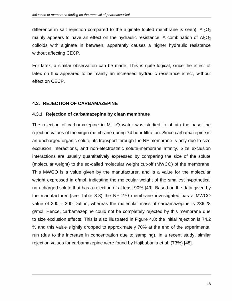
Influence of membrane fouling on the removal of pharmaceutical
46
difference in salt rejection compared to the alginate fouled membrane is seen), Al2O3
mainly appears to have an effect on the hydraulic resistance. A combination of Al2O3
colloids with alginate in between, apparently causes a higher hydraulic resistance
without affecting CECP.
For latex, a similar observation can be made. This is quite logical, since the effect of
latex on flux appeared to be mainly an increased hydraulic resistance effect, without
effect on CECP.
4.3. REJECTION OF CARBAMAZEPINE
4.3.1 Rejection of carbamazepine by clean membrane
The rejection of carbamazepine in Milli-Q water was studied to obtain the base line
rejection values of the virgin membrane during 74 hour filtration. Since carbamazepine is
an uncharged organic solute, its transport through the NF membrane is only due to size
exclusion interactions, and non-electrostatic solute-membrane affinity. Size exclusion
interactions are usually quantitatively expressed by comparing the size of the solute
(molecular weight) to the so-called molecular weight cut-off (MWCO) of the membrane.
This MWCO is a value given by the manufacturer, and is a value for the molecular
weight expressed in g/mol, indicating the molecular weight of the smallest hypothetical
non-charged solute that has a rejection of at least 90% [49]. Based on the data given by
the manufacturer (see Table 3.3) the NF 270 membrane investigated has a MWCO
value of 200 – 300 Dalton, whereas the molecular mass of carbamazepine is 236.28
g/mol. Hence, carbamazepine could not be completely rejected by this membrane due
to size exclusion effects. This is also illustrated in Figure 4.8: the initial rejection is 74.2
% and this value slightly dropped to approximately 70% at the end of the experimental
run (due to the increase in concentration due to sampling). In a recent study, similar
rejection values for carbamazepine were found by Hajibabania et al. (73%) [48].

Influence of membrane fouling on the removal of pharmaceutical
47
Figure 4.8: Experimental values for carbamazepine rejection by
the clean membrane as a function of time
Besides size exclusion effects, also non-electrostatic solute-membrane affinity will have
an effect on rejection. This will be dealt with in a further paragraph.
4.3.2 Rejection of carbamazepine by fouled membranes
Carbmazepine rejection of the fouled membranes is given in Figure 4.9. Fouling
obviously reduced the removal efficiency of this non-ionic hydrophobic trace organic.
However, the magnitude of decrease in rejection of carbamazepine was different for the
different foulants because of their different characteristics such as different size, charge
and hydrophobicity, and thus a different effect on membrane fouling as well.
0
20
40
60
80
100
0 10 20 30 40 50 60 70 80
Car
bam
aze
pin
e re
jcti
on
(%)
Time (hour)
0
20
40
60
80
100
0 10 20 30 40 50 60 70 80
Re
lati
ve r
ejc
tio
n (%
)
Time (hour)
Clean
Latex
Al2O3
SAa)

Influence of membrane fouling on the removal of pharmaceutical
48
Figure 4.9: Carbamazepine rejection behavior of fouled membrane with (a) the
absence of CaCl2, (b) the presence of CaCl2 and (c) combined foulants.
Figure 4.9a clearly shows that fouling layers of latex and aluminum oxide induced an
apparent decrease in the rejection of carbamazepine, which the values of relative
rejection at the end of the experimental runs were 75.9% and 70.6% respectively.
However, the curves describing the changes of carbamazepine rejection by these two
foulants are relatively similar. This is consistent with the effects of fouling on salt
rejection for these foulants.
The change in retention of carbamazepine in the presence of SA fouling was much more
pronounced than individual aluminum oxide or latex fouling. For instance, the rejection
of carbamazepine by SA fouled membrane decreased to 37.6% after 74 hour of
filtration. The decrease in rejection by SA fouling is consistent with the results obtained
0
20
40
60
80
100
0 10 20 30 40 50 60 70 80
Re
lati
ve r
eje
ctio
n (%
)
Time (hour)
CleanAl2O3+ CaCl2Latex + CaCl2SA + CaCl2
0
20
40
60
80
100
0 10 20 30 40 50 60 70 80
Rel
ativ
e r
eje
ctio
n (%
)
Time (hour)
Clean
Al2O3 + SA + CaCl2
SA+Latex+CaCl2
b)
c)
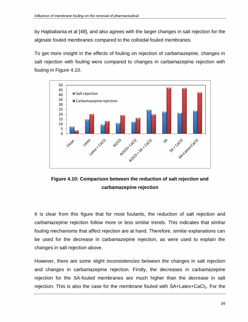
Influence of membrane fouling on the removal of pharmaceutical
49
by Hajibabania et al [48], and also agrees with the larger changes in salt rejection for the
alginate fouled membranes compared to the colloidal fouled membranes.
To get more insight in the effects of fouling on rejection of carbamazepine, changes in
salt rejection with fouling were compared to changes in carbamazepine rejection with
fouling in Figure 4.10.
Figure 4.10: Comparison between the reduction of salt rejection and
carbamazepine rejection
It is clear from this figure that for most foulants, the reduction of salt rejection and
carbamazepine rejection follow more or less similar trends. This indicates that similar
fouling mechanisms that affect rejection are at hand. Therefore, similar explanations can
be used for the decrease in carbamazepine rejection, as were used to explain the
changes in salt rejection above.
However, there are some slight inconsistencies between the changes in salt rejection
and changes in carbamazepine rejection. Firstly, the decreases in carbamazepine
rejection for the SA-fouled membranes are much higher than the decrease in salt
rejection. This is also the case for the membrane fouled with SA+Latex+CaCl2. For the
05
101520253035404550
Salt rejection
Carbamazepine rejection

Influence of membrane fouling on the removal of pharmaceutical
50
membrane fouled with SA+Al2O3+CaCl2, on the other hand, this difference between the
decrease in salt rejection and carbamazepine rejection was not observed.
This would seem to indicate that, although similar fouling mechanisms and influences on
rejection are at hand, there is another mechanisms playing a role for carbamazepine
rejection compared to salt rejection. This mechanism may be the non-electrostatic
interaction between the carbamazepine and the fouling layer, which can be calculated
from the surface tension values. Therefore, in the following paragraph, rejection values
are plotted as a function of interaction energies.
4.7. CARBAMAZEPINE-MEMBRANE AFFINITY
Table 4.4 gives an overview of the free energies of interaction, ΔGi, between
carbamazepine and the clean and fouled membranes, calculated from contact angle
values to evaluate the affinity between them.
Table 4.4: Surface tension components and the free-energy of intertactions
for clean and fouled membranes
Name γLWM γ+M γ-M γ tot ΔGi
(x10-18J)
Clean membrane 38.62 1x10⁻⁶ 42.01 38.63 2.53
Al2O3 41.97 1x10⁻⁶ 17.90 41.98 -2.39
Al2O3 + CaCl2 41.13 3.29 9.61 52.39 -5.07
Latex 40.93 1x10⁻⁶ 3.74 40.94 -7.06
Latex + CaCl2 37.49 1x10⁻⁶ 1x10⁻⁶ 37.47 -10.9
SA 31.02 1x10⁻⁶ 17.24 31.03 -1.63
SA + CaCl2 37.47 2.49 1x10⁻⁶ 37.48 -1.11
SA + Latex + CaCl2 39.89 1x10⁻⁶ 18.87 37.90 -1.99
SA + Al2O3 + CaCl2 47.54 4.21 1x10⁻⁶ 47.54 -12.0

Influence of membrane fouling on the removal of pharmaceutical
51
For the clean membrane, the free energy of interactions positive, indicating that no
spontaneous partitioning of carbamazepine into the membrane due to solute-membrane
affinity will occur. Consequently, the rejection of carbamazepine by the virgin membrane
was relatively high, since non-electrostatic repulsion was present in addition to steric
effects.
In contrast to the clean membrane, all fouled membranes (or at least the fouling layers
on top of the membranes), have significant affinity for carbamazepine, as can be seen
from negative values of ΔGi in Table 4.4. This confirms that the transfer of
carbamazepine to the membrane will be facilitated in the presence of fouling layer which
could give an indication for the lower rejection values of carbamazepine observed for the
fouled membranes.
In the results shown above, it was shown that carbamazepine rejection closely followed
salt rejection for the colloidal fouled membranes, but a higher decrease in rejection was
seen for carbamazepine compared to the salt rejection for all sodium alginate fouled
membranes (including the combined foulants), except for the combined fouling with
Al2O3 and sodium alginate. Since the colloidal fouled membranes show similar trends for
carbamazepine and salt rejection, the same mechanisms of rejection and influence of
fouling on rejection apply.
For the SA fouled (including combined fouling) membranes, however, an extra
mechanism seems to play a role. This could be the effect of non-electrostatic solute
membrane affinity. When carbamazepine rejection differences with the clean membrane
are plotted for all the sodium-alginate fouled membranes as a function of solute-
membrane interaction, it is clear that the SA-fouled, the SA+CaCl2 fouled and the
SA+Latex+CaCl2 fouled membranes all have similar behavior and more or less similar
interaction energies. For the SA+Al2O3+CaCl2 fouled membrane, however, there is a
much more intense interaction (attraction) between the carbamazepine and the foulant.

Influence of membrane fouling on the removal of pharmaceutical
52
Figure 4.11: The reductions of salt rejection and carbamazepine rejection
vs. interaction energy
This could be a hint at what is happening for the fouled membranes. For the colloidal
fouled membranes, there is no clear effect that CECP is playing a role. For all SA-fouled
membranes, however, it has been shown that CECP is indeed affecting rejection. It
could be theoretically expected that if carbamazepine shows more affinity for the foulant,
this would lead to more pronounced CECP. However, here, an opposite trend seems to
emerge. This can be explained as follows: convective drag of carbamazepine towards
the membrane will not be significantly altered by the interaction energy between
carbamazepine and the foulants, since the driving force for permeation through the large
pore size of the fouling layer is relatively high. However, the interaction energy will have
a pronounced effect on back-diffusion, since the driving force for back-diffusion is much
lower. Therefore, it is expected that for the fouling layers which have a higher affinity for
carbamazepine, the back-diffusion will occur much faster than for the other foulants,
since the solute is attracted by the foulant and thus partitions back to the feed through
the foulant layer much easier. This explains the completely different trends seen for
SA+Al2O3+CaCl2 compared to the similar behavior of all the other SA-fouled
membranes.
-140
-120
-100
-80
-60
-40
-20
0
20
40
60
Salt rejection
Carbamazepine rejection
Interaction energy

Influence of membrane fouling on the removal of pharmaceutical
53
CHAPTER 5
CONCLUSIONS AND RECOMMENDATIONS
5.1. CONCLUSIONS
In this dissertation, three types of foulants were used to simulate membrane fouling and
to assess the impact of fouling on the rejection of carbamazepine by NF/RO
membranes.
The reported result indicated that the largest flux decline was observed when the
membrane was fouled by latex colloids. However, there was no flux decline
observed on filtration of feed water containing aluminum oxide particles. The flux
decline behavior with sodium alginate was in between that of these two foulants.
The presence of calcium chloride generally improved the fluxes in both experiments
with sodium alginate and latex, compared to that of the individual foulant. With
combined fouling experiments, the fluxes illustrated synergistic effects of combined
foulants but the flux declines are not as significant as latex.
Aluminum oxide and latex were only caused a slight decrease since there was no
presence of cake-enhanced concentration polarization. Nevertheless, sodium
alginate caused the most remarkable loss in salt rejection which can be explained by
the strong impact of alginate cake to the hindrance of back – diffusion of salt This
was also hypothesized that the same fouling mechanisms induced the similar
behaviors for the combinations of sodium alginate with aluminum oxide and latex.
Interestingly, the carbamazepine rejection almost followed the trends of salt
rejection. This indicated that the existence of similar fouling mechanisms between
carbamazepine and salt rejection.
In term of free energies of interactions (ΔGi), all fouled membranes had negative
values which showed a significant affinity to carbamzepine and therefore, lower

Influence of membrane fouling on the removal of pharmaceutical
54
rejection values were observed. It was concluded that non-electrostatic solute-
membrane affinity played a crucial role for the sodium alginate fouled membranes. It
was concluded that non-electrostatic solute-membrane affinity played a crucial role
for the sodium alginate fouled membranes. Indeed, the interaction energy have
significantly effects on the back-diffusion since the driving force for the back-
diffusion is much lower compared to that of the permeate flow. Back-diffusion is
likely to occur much faster for fouling layers have a high affinity for carbamazepine.
5.2. RECOMMENDATIONS FOR FUTURE WORKS
Based on the conclusions obtained in this study, the following recommendations are
made for future works:
This study was carried out with only carbamazepine in the feed water. In practice,
there are other trace organic contaminants detected in high concentrationsin
drinking water resources. Some of the contaminants which may pose a health risk
to human beings, include sulfamethoxazole, bisphenol A, N-
nitrosodimethylamine, 17β-Estradiol and so on. More experiments with a wide
range of solutes with varying physico-chemical properties will give a clearer
observation about the influence of fouling on their removal.
Future research should include atomic force microscopy (AFM) and scanning
electron microscopy (SEM) analysis of fouled membranes in order to elucidate
the thickness of the cake layers, as well as the levels of coverage of the
membranes by the foulants.
A model that predicts rejection of organics by high pressure membrane in water
purification has been introduced before been introduced, by Verliefde et
al.(2009).However, it becomes clear from the experiments carried out here that
this model is only applicable for clean membranes and not always efficient in
predicting observed behavior when the membranes are fouled. Therefore, there is
a need for development of models that will predict and explain behavior of NF/RO

Influence of membrane fouling on the removal of pharmaceutical
55
membrane when they are fouled by colloids, natural organic matter and
combinations of such foulants. Based on result of this study, a mathematically
model for prediction of organic pollutants removal by these types of foulants
should be considered and published in the future. One possible way of doing this,
would be to deal with the foulant layer as a secondary membrane on the dense
membrane, and integrate the convection-diffusion equation not only over the
membrane, but on the combined system of membrane and fouling layer (a
“membrane-in-series” model).

Influence of membrane fouling on the removal of pharmaceutical
56
REFERENCES
1. T. Heberer. Occurance, fate and removal of pharmaceutical residues in the aquatic
environment: a review of recent research data. Toxicology letters 131 (2002), 5 –
17.
2. P.Xu, J.E. Drewes, T.U. Kim, C. Bellona, G. Amy. Effect of membrane fouling on
transport of organic contaminants in NF/RO membrane applications. Journal of
Membrane Science 279 (2006), 165-175.
3. A.E. Contreras, A. Kim and Q. Li. Combined fouling of nanofiltration membranes:
mechanisms and effect of organic matter. Journal of Membrane Science 327
(2009), 87 – 95.
4. A.R.D. Verliefde, E.R. Cornelissen, S.G.J.Heijman, I.Petrinic, T.Luxbacher,
G.L.Amy, B.V.D. Bruggen, J.C.V. Dijk. Influence of membrane fouling by
(pretreated) surface water on rejection of pharmaceutically active compounds
(PhACs) by nanofiltration membranes. Journal of Membrane Science 330 (2009),
90 - 103.
5. R.D. Cohen and R.F. Probstein. Colloidal fouling of Reverse Osmosis Membranes.
Journal of Colloid and Interface Science, 114 (1986), 194 – 207.
6. E.M.V. Hoek, A.S. Kim, M. Elimmelech. Influence of crossflow membrane filter
geometry and shear rate on colloidal fouling in reverse osmosis and nanofiltration
separations. Environmental Engineering Science 19 (2002), 357 – 372.
7. H.Y. Ng, M. Elimelech. Influence of colloidal fouling on rejection of trace organic
contaminants by reverse osmosis. Journal of Membrane Science 244 (2004), 215
– 226.
8. S.G. Yiantsios and A.J. Karabelas. The effect of colloid stability on membrane
fouling. Desalination 118 (1998), 143 – 152.
9. X.Zhu and M.Elimelech. Fouling of reverse osmosis membranes by aluminum
oxide colloids. Journal of environmental engineering (1995), 884 – 892.
10. L.D. Nghiem, S. Hawkes. Effect of membrane fouling on the nanofiltration of
pharmaceutically active compounds (PhACs): Mechanism and the role of
membrane pore size. Seperation and Purification Technology 57 (2007), 182 –
190.
11. S.G. Yiantsios, D. Sioutopoulos, A.J. Karabelas. Colloidal fouling of RO
membranes: an overview of key issues and efforts to develop improved prediction
techniques. Desalination 183 (2005), 257 – 272.
12. L.D. Nghiem, P.J. Coleman, C. Espendiller. Mechanisms underlying the effects of
membrane fouling on the nanofiltration of trace organic contaminants. Desalination
250 (2010), 682 – 687.

Influence of membrane fouling on the removal of pharmaceutical
57
13. L.D. Nghiem, C. Espendiller, G. Braun. Influence of organic and colloidal fouling on
the removal of sulphamethoxazole by nanofiltration membranes. Water Science
and Technology 58 (2008), 163 – 169.
14. M. Mulder. Basic principles of membrane technology. Kluwer Academic Publishers
(1996).
15. The world membrane separation technologies, Industry study with forecasts for
2012 and 2017. The Freedonia group (2009), 1 – 34.
16. W.R. Bowen, A.W. Mohammad and N. Hilal. Characterisation of nanofiltration
membranes for predictive purposes use of salts, uncharged solutes and atomic
force microscopy. Journal of Membrane Science 126 (1997), 91 – 105.
17. P.V.D Meeren. Membrane processes in environmental technology course note.
Univeristy of Gent (2011).
18. B.V.D. Bruggen, L. Braeken, C. Vandecasteele. Flux decline in nanofiltration due to
adsorption of organic compounds. Seperation and Purification Technology 29
(2003) 23 – 31.
19. S. J. Khan, J. E. Ongerth. Modelling of pharmaceutical residues in Australian
sewage by quantities of use and fugacity calculation. Chemosphere 54 (2004), 355
-367.
20. M. S. Diaz-Cruz, M. J. L Alda, D. Barcelo. Environmental behavior and analysis of
veterinary and human drugs in soils, sediments and sludge. Trends in Analytical
Chemistry 22 (2003), 340 – 351.
21. Pharmaceuticals in our water supplies.
http://ag.arizona.edu/azwater/awr/july00/feature1.htm. Last accessed on
5/15/2012.
22. N. Le-Minh, S.J. Khan, J.E.Drewes, R.M. Stuetz. Fate of antibiotics during
municipal water recycling treatment. Water Research 44 (2010), 4295 – 4323.
23. J. Beausse. Selected drugs in solid matrices: a review of environmental
determination, occurrence and properties of principal substances. Trends in
Analytical Chemistry, Vol 23 (2004), 10-11.
24. A.R.D. Verliefde, S.G.J Heijman, E.R.Cornelissen, G.L. Amy, B.V.D Bruggen and
J.C.V Dijk. Rejection of trace organic pollutants with high pressure membrane
(NF/RO). Volume 27 Environmental Progress (2008), 181 - 193.
25. B.V.D. Bruggen, C. Vandecasteele. Modelling of the retention of uncharged
molecules with nanofiltration. Water Research 36 (2002), 1361-1365.
26. A.R.D. Verliefde, E.R.Cornelissen, S.G.J.Hejiman, J.Q.J.C. Verberk, G.L. Amy,
B.V.D Bruggen, J.C.V. Dijk. The role of electrostatic interaction on the rejection of
organic solutes in aqueous solutions with nanofiltation. Journal of Membrane 322
(2008), 53.
27. C. Liu, S. Caothien, J. Hayes, T.Caothuy, T. Otoyo, T. Ogawa. Membrane
chemical cleaning: From art to science. American Water Works Association
MTC53852 (2001), 1-12.

Influence of membrane fouling on the removal of pharmaceutical
58
28. C. Bellona, J.E. Drewes, P. Xu, G. Amy. Factors affecting the rejection of organic
solutes during NF/RO treatment – a literature review. Water Research 38 (2004),
2795 – 2809.
29. K.S. Spiegler and O. Kedem. Thermodynamics of hyperfiltration (reverse osmosis):
criteria for efficient membranes. Desalination 1(1966), 311 – 326.
30. L. Puijker, M. Mons. Pharmaceuticals and personal care products in water cycle –
international review. Kiwa report KWR 04. 013. Kiwa N.V. Water Research,
Nieuwegein, The Netherlands, 2004.
31. C.D. Anderson and E.S. Daniels. Emulsion Polymerization and Latex Applications.
(2003), 156p.
32. R. Duwadi. Electric field assisted ultrafiltration: modeling and experimental
validation. Department of applied analytical and physical chemistry, Particle &
Interfacial and Technology Group, Gent University (2009), 95p.
33. K. Kotcharaksa. The mechanisms, Products, and Kinetic of Carbamazepine-Free
Chlorine Reactions. Faculty of the Virginia Polytechnic Institute and State
University (2008), 1-45.
34. D. Fatta and A. Achilleos. Analytical methods for tracing pharmaceutical residue in
water and wastewater. Trends in Analytical Chemistry 26 (2007), 515 – 533.
35. S. A. Snyder, J. Leising, P. Westerhoff, Y. Yoon, H. Mash and B. Vanderford.
Biological and physical Attentuation of Endocrine Disruptors and Pharmaceuticals:
Implications for Water Use. Ground Water Monitoring and Remediation 24 (2004),
108 – 118.
36. E.M.V. Hoek and M. Elimelech. Cake-enhanced concentration polarization: A new
fouling mechanism for salt-rejection membranes. Environmental Science &
Technology 37 (2003), 5581 – 5588.
37. K. Boussu, Y. Zhang, J. Coquyt, P.V.D. Meeren, A. Volodin, C.V. Haesendonck,
J.A. Martens, B.V.D. Bruggen. Characterization of polymeric nanofiltration
membranes for systematic analysis of membrane performance. Journal of
Membrane Science 278 (2006), 418 – 427.
38. N. Hilal, H. Al-Zoubi, N.A. Darwish, A.W. Mohammad. Characterisation of
nanofiltration membranes using atomic force microscopy. Desalisation 177 (2005),
187 – 199.
39. K. Kontturi, M.Vouristo. Adsorption of globular proteins on polymerics microfiltration
membranes. Desalination 104 (1996), 99 – 105.
40. A. Al-Amoudi, R.W. Lovitt. Fouling strategies and the cleaning system of NF
membranes and factors affecting cleaning efficiency. Journal of Membrane
Science 303 (2007), 4 - 28.
41. N.D. Lawrence, J.M. Perere, M. Iyer, M.W. Hickey and G.W. Stevens. The use of
streaming potential measurements to study the fouling and cleaning of ultrafiltration
membranes. Seperation and Purification Technology, 48 (2006), 106 – 112.

Influence of membrane fouling on the removal of pharmaceutical
59
42. A.R.D. Verliefde, E.R.Cornelissen, S.G.J.Hejiman, E.M.V. Hoek, G.L. Amy, B.V.D.
Bruggen, and J.C.V. Dijk. Influence of Solute-Membrane Affinity on Rejection of
Uncharged Organic Solutes by Nanofiltration Membranes. Environmental Science
and Technology 43 (2009), 2400 – 2406.
43. J.A. Brant and A.E. Childress. Assessing short-range membrane –colloids
interactions using surface energetic. Journal of Membrane Science 203 (2002),
257 – 273.
44. B.J. Marinas and R.E. Selleck. Reverse osmosis treatment of multicomponent
electrolyte solutions. Journal of Membrane Science 72 (1992), 211 – 229.
45. R. Kummert and W. Stumm. The surface complexation of Organic acids on
hydrous Al2O3. Journal of Colloidal and Interace Science, 75 (1986), 373 – 385.
46. S.J. Hwang, D.J. Chang, C.H.Chen. Steady-state permeate flux for particle cross-
flow filtration. The Chemical Engineering Journal 61(1996), 171 – 178.
47. W.J.C. Ven, K.V. Sant, I.G.M. Punt, A. Zwijnenburg, A.J.B. Kemperman, W.G.J.
Meer, M. Wessling. Hollow fiber dead-end ultrafiltration: Influence of ionic
environment on filtration of alginate. Journal of Membrane Science 308 (2008), 218
-229.
48. S. Hajibabania, A. Verliefde, J.E. Drewes, L.D. Nghiem, J. McDonal, S. Khan and
P. Le-Clech. Effect of fouling on removal of trace organic compounds by
nanofiltration. Drinking Water Engineering and Science Discussions 4 (2011), 117
– 149.
49. B.V.D. Bruggen, J. Schaep, D. Wilms, C. Vandecasteele. Influence of molecular
size, polarity and charge on the retention of organic molecules by nanofiltration.
Journal of Membrane Science 156 (1999), 29 – 41
50. S.Hong, R.S. Faibish and M. Elimelech. Kinetics of Permeate Flux Decline in
Crossflow Membrane Filtration of Colloidal Suspensions. Journal of Colloid and
Interface Science 196 (1997), 267 – 277.
51. L.D. Nghiem, A.I. Schafer and M. Elimelech. Role of electrostatic interactions in the
retention of pharmaceutically active contaminants by a loose nanofiltration
membrane. Journal of Membrane Science 286 (2006), 52-59.
52. A.R.D. Verliefde, S.G.J. Heiman, E.R. Cornelissen, G. Amy, B.V.D Bruggen and
J.C.V. Dijk. Influence of electrostatic interactions on the rejection with NF and
assessment of the removal efficiency during NF/GAC treatment of
pharmaceutically active compounds in surface water. Water research 41 (2007),
3227 – 3240.
53. W. Norde, Colloids and Interfaces in Life Sciences. Dekker, New York, 2003.
54. G. Singh and L.Song. Quantifying the effect of ionic strength on colloidal fouling
potential in membrane filtration. Journal of Colloid and Interface Science 284
(2005), 630 – 638.
Influence of membrane fouling on the removal of pharmaceutical
60
55. M. Zhang and L. Song. Mechanisms and parameters affecting flux declinein cross-
flow microfiltration and ultrafiltration of colloids. Environmental Science and
Technology, 34 (2000), 3767 – 3773.
56. P.V.D. Meeren, H. Saveyn, S.B. Kassa, W. Doyen and R. Leysen. Colloid-
membrane interaction effects on flux decline during cross-flow ultrafiltration of
colloidal silica on semi-ceramic membrane. Physical Chemistry Chemical Physics,
6 (2004), 1408 – 1412.
57. M.A. Zazouli, M. Ulbricht, S. Nasseri, H. Susanto. Effect of hydrophilic and
hydrophobic organic matter on amoxicillin and cephalexin residuals rejection from
water by nanofiltration. Iranian Journal of Environmental Health Science and
Engineering 7 (2010), 15 – 24.
58. Q. Li, M. Elimelech. Synergistic effects in combined fouling of a loose nanofiltration
membrane by colloidal materials and natural organic matter. Journal of Membrane
Science 278 (2006), 72 – 82.
59. G. Artug, J. Hapke. Characterization of nanofiltration membranes by their
morphology, charge and filtration performance parameters. Desalination 200
(2006), 178 – 180.
60. E.M. Vrijenhoek, S. Hong, M. Elimelech. Influence of membrane surface properties
on initial rate of colloidal fouling of reverse osmosis and nanofiltration membranes.
Journal of Membrane Science 188 (2001), 115 - 128.
61. J. Zhao and W. Brown. Surface Characteristics of Polystyrene Latex Particles and
Comparison with Styrene-Butadiene Copolymer Latex Particles Using Dynamic
Light Scattering and Electrophoretic Light Scattering Measurements. Journal of
Colloid and Interface Science 179 (1996), 255 – 260.
62. W.S. Ang, A. Tiraferri, K.L. Chen, M. Elimelech. Fouling and cleaning of RO
membranes fouled by mixtures of organic foulants simulating wastewater effluent.
Journal of Membrane Science 376 (2011), 196 – 206.
63. A.V. Delgado, F. Gonzalez-Caballero, R.J. Hunter, L.K. Koopal, and J. Lyklema.
Measurment and Interpretation of Electrokinetic phenomena. Pure and Applied
Chemistry 77, 1753 – 1805.
64. S.H. Belhrens and M. Borkovec. Influence of secondary interaction energy
minimum on the early stages of colloidal aggregation. Journal of Colloid and
Interface Science 225 (2000), 460 – 465.
65. K. Listiarini, W. Chun, D.D. Sun, J.O. Leckie. Fouling mechanism and resistance
analyses of the systems containing sodium alginate, calcium, alum and their
combination in dead-end fouling of nanofiltration membranes. Journal of
Membrane Science 344 (2009), 244 -251.
66. J.W.S. Goossens and A. Zembrod. Characterization of the surface of polymer
lattice by photon correlation spectroscopy. Journal of Dispersion Science and
Technology 2 (1981), 255 – 266.

Influence of membrane fouling on the removal of pharmaceutical
61
67. M.A. Zazouli, M. Ulbricht, S. Nasseri, H. Susanto. Effect of hydrophilic and
hydrophobic organic matter on amoxicillin and cephalexin residuals rejection from
water by nanofiltration. Iran. J. Environ. Health. Sci. Eng 7 (2010), 15 – 24.
68. S. Lee, J. Cho, M. Elimelech. Influence of colloidal fouling and feed water recovery
on salt rejection of RO and NF membrane. Desalination 160 (2004), 1 – 12.
69. L. Braeken, R. Ramaekers, Y. Zhang, G. Maes, B.V.D Bruggen, C. Vandecasteele.
Influence of hydrophobicity on retention in nanofiltration of aqueous solutions
containing organic compounds. Journal of Membrane Science 252 (2005), 195 –
203.
70. Y. Yoon, P. Westerhoff, S.A. Snyder, E.C. Wert. Nanofiltration and Ultrafiltration of
endocrine disrupting compounds, pharmaceuticals and personal care products.
Journal of membrane Science 270 (2006), 88.
71. A.J. Kerchove and M. Elimelech. Formation of Polysaccharides Gel layers in the
Presence of Ca2+ and K+ ions: measurement and mechanisms.
Biomacromolecules 8 (2007), 113 – 121.

Influence of membrane fouling on the removal of pharmaceutical
62
APPENDIX
Table 1: Measured properties of the NF 270 membrane
Properties Value
Permeability, l/m2.h.bar 10.5 m/s 8.8x10⁻⁶
Contact angle water 42o ± 0.5o glycerol 66o ± 1.3o diiodomethane 33o ± 1.6o
Figure 1: Variation of the zeta potential of NF 270 membrane with pH.
Figure 2: SEM images of the surface (a) and bottom (b) of NF 270 membrane
-60
-40
-20
0
20
40
60
0 1 2 3 4 5 6 7 8 9 10 11 12
Zet
a P
ote
nti
al
(mV
)
pH
Clean NF 270 Membrane
a) b)

Influence of membrane fouling on the removal of pharmaceutical
63
Figure 3: Zeta potential as a function of pH for Al2O3, sodium alginateand latex
Table 2: Particles size of different foulants
Foulants Diameter (nm) SD (nm)
Al2O3 139.4 2.8 Al2O3 + CaCl2 143.2 1.6 Latex 153.6 2.9 Latex + CaCl2 159.8 1.5 SA 300.7 5.4 SA +CaCl2 1938.0 1044.8 Al2O3 +SA +CaCl2 198.0 2.1 Latex +SA+ CaCl2 178.8 1.0
-60
-40
-20
0
20
40
60
0 2 4 6 8 10 12
Zeta
po
ten
tial
(mV
)
pH
Al2O3
-60
-40
-20
0
20
40
60
0 2 4 6 8 10 12
Zeta
po
ten
tial
(mV
)
pH
Latex
-60
-40
-20
0
20
40
60
0 2 4 6 8 10 12
Zeta
po
ten
tial
(mV
)
pH
Sodium alginate

Influence of membrane fouling on the removal of pharmaceutical
64
Table 4: Contact angles of fouled membranes with three liquid probes
Fouling experiment Diiodomethane (o) Glycerol (o) Water (o)
Al2O3 28.2± 3.7 64.0±1.6 62.6±1.0
Al2O3 + CaCl2 39.1±3.1 53.7±2.2 59.7± 2.8
Latex 31.9± 3.6 62.0±2.4 84.2±2.9
Latex + CaCl2 38.3± 3.2 91.1±2.5 77.7±2.9
SA 50.1±2.2 80.9±1.3 71.1±2.6
SA +CaCl2 43.4± 3.7 62.4±2.4 71.3±2.8
Al2O3 +SA +CaCl2 18.3± 2.1 43.3±1.4 67.7±1.7
Latex +SA+ CaCl2 41.3±1.9 65.6± 1.8 61.8±1.3