Influence of electrostatic force and the van der Waals attraction on the pull-in instability of the...
11
ARTICLE Influence of electrostatic force and the van der Waals attraction on the pull-in instability of the CNT-based probe–actuator Norodin Fazli, Ali Koochi, Asieh Sadat Kazemi, and Mohamadreza Abadyan Abstract: In recent years, carbon nanotubes (CNTs) have attracted great attention in the fabrication of probe tips and actuators for scanning microscopes. Herein, the pull-in instability of CNT-based probe is investigated using a nanoscale continuum model. The Euler–Bernoulli beam theory is applied to model the elastic response of the CNT. The van der Waals attraction is computed from the simplified Lennard-Jones potential. Two analytical methods (i.e., Homotopy perturbation method and Adomian decompo- sition method) are applied to solve the nonlinear governing equation of the system. Furthermore, the obtained results are validated by comparing with experimental results in the literature as well as numerical solutions of the finite difference method. The pull-in parameters are determined and effect of van der Waals force and a geometrical parameter effect on the instability behavior of the CNT is discussed. Moreover, the detachment length and minimum initial gap of the freestanding CNT probe are determined. PACS Nos.: 85.85.+j, 61.48.De, 46.32.+x, 45.10.−b. Résumé : Ces dernières années, les nanotubes de carbone (CNTs) ont fortement attiré l’attention pour la fabrication de pointe de sonde et d’actuateurs pour les microscopes a ` balayage. Nous étudions ici l’instabilité de collage d’une sonde basée sur des CNT en utilisant un modèle du continuum a ` l’échelle nano. Nous appliquons la théorie de la poutre de Euler–Bernouilli pour modéliser la réponse élastique du CNT. Nous calculons l’attraction de van der Waals a ` partir d’un potentiel simplifié de Lennard-Jones. Deux méthodes analytiques, a ` savoir la méthode perturbative d’homotopie et la décomposition d’Adomian, sont utilisées pour résoudre les équations directrices non linéaires du système. Nous validons nos résultats en les comparant a ` des données expérimentales trouvées dans la littérature et avec des résultats de calcul par éléments finis. Nous déterminons les paramètres de collage et discutons les effets de la force de van der Waals et du paramètre géométrique sur l’instabilité du CNT. Nous déterminons aussi la longueur de décollement et la séparation initiale minimale de la sonde CNT libre. [Traduit par la Rédaction] 1. Introduction With the recent growth in nanotechnology, carbon nanotubes (CNTs) are increasingly applied in developing atomic force micro- scope (AFM) probe tips [1–3], nanotweezers [4], and nanoelectro- mechanical system (NEMS) actuators [5–8]. It has been reported that the stiffness, flexibility, and strength of CNTs are much higher than conventional materials [9]. Consider a typical cantile- ver CNT probe suspended near an electrode surface with a small gap in between. Applying a voltage difference between the canti- lever CNT and the conductive ground causes the CNT to deflect and be attracted toward the ground surface because of the pres- ence of electrostatic forces. Once this voltage exceeds a critical value, an increase in the electrostatic force becomes greater than the corresponding increase in the restoring force, resulting in the unstable collapsing of the CNT to the ground position. This behav- ior is known as the pull-in instability and the critical voltage is called the pull-in voltage. When the rate of voltage variation can- not be ignored (for example in suddenly electrostatic charging), the dynamic issues (i.e., the effect of inertia) should be considered in the model [10]. The pull-in instability related to this situation is called dynamic pull-in. As the gap decreases from micro- to nanoscale, the van der Waals interaction predominates. The prediction of the molecular force-induced instability of CNT is a critical subject in the design of AFM probes and NEMS switches and actuators. With a decrease in the distance between the AFM probe and the sample surface, the probe jumps onto the contact with the substrate, this negates its imaging performance [11–13]. Similarly if the minimum gap between the switch and substrate is not considered, a NEMS switch might adhere to the substrate even without an applied voltage because of the presence of intermolecular forces [14–17]. To study nanostructures, several approaches have been em- ployed. Molecular dynamics and molecular mechanics simula- tions were used to study the mechanical behavior of carbon-based nanomaterials [18–21]. However these methods are very time- consuming and might not be easily used in modeling the perfor- mance of complex structures. An alternative reliable approach to simulate the instability behavior of a CNT interacting with an extremely large number of ground atoms is to apply an appropri- ate nanoscale continuum model. A hybrid continuum model can be similarly used to calculate the van der Waals energy, in lieu of the discrete Lennard-Jones potential [20, 21]. Although continuum models are more time-saving than the molecular mechanics and molecular dynamics, their approach often leads to nonlinear equa- tions that might not be amenable by common analytical methods [22, 23]. To solve the nonlinear equation of nanosystems, one can apply analytical methods such as Adomian decomposition [24–28], variational iteration [29], and homotopy perturbation [30–33]. In this paper, we investigate the pull-in instability of the canti- lever CNT probe–actuator by taking into account the effect of Coulomb electrostatic and van der Walals molecular forces. We apply a nanoscale continuum model based on Euler beam theory Received 24 April 2013. Accepted 8 October 2013. N. Fazli. Shahrekord University of Medical Sciences, Shahrekord, Iran. A. Koochi and M. Abadyan. Shahrekord Branch, Islamic Azad University, Shahrekord, Iran. A.S. Kazemi. Bojnourd Branch, Islamic Azad University, Bojnourd, Iran. Corresponding author: Mohamadreza Abadyan (e-mail: [email protected]). 1047 Can. J. Phys. 92: 1047–1057 (2014) dx.doi.org/10.1139/cjp-2013-0202 Published at www.nrcresearchpress.com/cjp on 18 December 2013. Can. J. Phys. Downloaded from www.nrcresearchpress.com by Ohio State University on 12/22/14 For personal use only.
-
Upload
mohamadreza -
Category
Documents
-
view
214 -
download
0
Transcript of Influence of electrostatic force and the van der Waals attraction on the pull-in instability of the...

ARTICLE
Influence of electrostatic force and the van der Waals attractionon the pull-in instability of the CNT-based probe–actuatorNorodin Fazli, Ali Koochi, Asieh Sadat Kazemi, and Mohamadreza Abadyan
Abstract: In recent years, carbon nanotubes (CNTs) have attracted great attention in the fabrication of probe tips and actuatorsfor scanning microscopes. Herein, the pull-in instability of CNT-based probe is investigated using a nanoscale continuum model.The Euler–Bernoulli beam theory is applied to model the elastic response of the CNT. The van der Waals attraction is computedfrom the simplified Lennard-Jones potential. Two analytical methods (i.e., Homotopy perturbation method and Adomian decompo-sition method) are applied to solve the nonlinear governing equation of the system. Furthermore, the obtained results are validatedby comparing with experimental results in the literature as well as numerical solutions of the finite difference method. The pull-inparameters are determined and effect of van der Waals force and a geometrical parameter effect on the instability behavior of the CNTis discussed. Moreover, the detachment length and minimum initial gap of the freestanding CNT probe are determined.
PACS Nos.: 85.85.+j, 61.48.De, 46.32.+x, 45.10.−b.
Résumé : Ces dernières années, les nanotubes de carbone (CNTs) ont fortement attiré l’attention pour la fabrication de pointede sonde et d’actuateurs pour les microscopes a balayage. Nous étudions ici l’instabilité de collage d’une sonde basée sur des CNTen utilisant un modèle du continuum a l’échelle nano. Nous appliquons la théorie de la poutre de Euler–Bernouilli pour modéliser laréponse élastique du CNT. Nous calculons l’attraction de van der Waals a partir d’un potentiel simplifié de Lennard-Jones. Deuxméthodes analytiques, a savoir la méthode perturbative d’homotopie et la décomposition d’Adomian, sont utilisées pour résoudre leséquations directrices non linéaires du système. Nous validons nos résultats en les comparant a des données expérimentales trouvéesdans la littérature et avec des résultats de calcul par éléments finis. Nous déterminons les paramètres de collage et discutons les effetsde la force de van der Waals et du paramètre géométrique sur l’instabilité du CNT. Nous déterminons aussi la longueur de décollementet la séparation initiale minimale de la sonde CNT libre. [Traduit par la Rédaction]
1. IntroductionWith the recent growth in nanotechnology, carbon nanotubes
(CNTs) are increasingly applied in developing atomic force micro-scope (AFM) probe tips [1–3], nanotweezers [4], and nanoelectro-mechanical system (NEMS) actuators [5–8]. It has been reportedthat the stiffness, flexibility, and strength of CNTs are muchhigher than conventional materials [9]. Consider a typical cantile-ver CNT probe suspended near an electrode surface with a smallgap in between. Applying a voltage difference between the canti-lever CNT and the conductive ground causes the CNT to deflectand be attracted toward the ground surface because of the pres-ence of electrostatic forces. Once this voltage exceeds a criticalvalue, an increase in the electrostatic force becomes greater thanthe corresponding increase in the restoring force, resulting in theunstable collapsing of the CNT to the ground position. This behav-ior is known as the pull-in instability and the critical voltage iscalled the pull-in voltage. When the rate of voltage variation can-not be ignored (for example in suddenly electrostatic charging),the dynamic issues (i.e., the effect of inertia) should be consideredin the model [10]. The pull-in instability related to this situation iscalled dynamic pull-in.
As the gap decreases from micro- to nanoscale, the van derWaals interaction predominates. The prediction of the molecularforce-induced instability of CNT is a critical subject in the designof AFM probes and NEMS switches and actuators. With a decreasein the distance between the AFM probe and the sample surface,
the probe jumps onto the contact with the substrate, this negatesits imaging performance [11–13]. Similarly if the minimum gapbetween the switch and substrate is not considered, a NEMSswitch might adhere to the substrate even without an appliedvoltage because of the presence of intermolecular forces [14–17].
To study nanostructures, several approaches have been em-ployed. Molecular dynamics and molecular mechanics simula-tions were used to study the mechanical behavior of carbon-basednanomaterials [18–21]. However these methods are very time-consuming and might not be easily used in modeling the perfor-mance of complex structures. An alternative reliable approach tosimulate the instability behavior of a CNT interacting with anextremely large number of ground atoms is to apply an appropri-ate nanoscale continuum model. A hybrid continuum model canbe similarly used to calculate the van der Waals energy, in lieu ofthe discrete Lennard-Jones potential [20, 21]. Although continuummodels are more time-saving than the molecular mechanics andmolecular dynamics, their approach often leads to nonlinear equa-tions that might not be amenable by common analytical methods[22, 23]. To solve the nonlinear equation of nanosystems, one canapply analytical methods such as Adomian decomposition [24–28],variational iteration [29], and homotopy perturbation [30–33].
In this paper, we investigate the pull-in instability of the canti-lever CNT probe–actuator by taking into account the effect ofCoulomb electrostatic and van der Walals molecular forces. Weapply a nanoscale continuum model based on Euler beam theory
Received 24 April 2013. Accepted 8 October 2013.
N. Fazli. Shahrekord University of Medical Sciences, Shahrekord, Iran.A. Koochi and M. Abadyan. Shahrekord Branch, Islamic Azad University, Shahrekord, Iran.A.S. Kazemi. Bojnourd Branch, Islamic Azad University, Bojnourd, Iran.Corresponding author: Mohamadreza Abadyan (e-mail: [email protected]).
1047
Can. J. Phys. 92: 1047–1057 (2014) dx.doi.org/10.1139/cjp-2013-0202 Published at www.nrcresearchpress.com/cjp on 18 December 2013.
Can
. J. P
hys.
Dow
nloa
ded
from
ww
w.n
rcre
sear
chpr
ess.
com
by
Ohi
o St
ate
Uni
vers
ity o
n 12
/22/
14Fo
r pe
rson
al u
se o
nly.

to derive the nonlinear constitutive equation of the system. Fur-thermore, we utilize the Homotopy perturbation method (HPM)to solve the governing equation of this CNT-based system as wellas Adomian decomposition method (ADM). The obtained resultsare verified by comparing with those from the literature and nu-merical solutions of the finite difference method (FDM).
2. Theoretical modelLet us consider a freestanding multiwalled CNT above a ground
plane consisting of multiple graphene layers, with an interlayerdistance of d = 3.35 Å, as illustrated in Fig. 1. The length of the CNTis L and the initial gap between the CNT and the ground is D. Theboundary conditions of the CNT are defined as a cantilever fixed atone end with no displacement and rotation, and traction free atthe free end with no shear force and moment.
2.1. Coulomb attractionWhen a conductive nanotube is placed over a conductive sub-
strate (in the presence of an applied potential difference betweenthe tube and the electrode), the electrostatic charge is induced onboth the tube and the substrate. To calculate the electrical forcesacting on the tube, a capacitance model may be used. For conduc-tive cylinder with infinite length, the capacitance per unit lengthis given by [34]
C(D) �2��0
arccosh[1 � (D/Rw)](1)
where D is the initial distance between the tube and ground plate,and �0 = 8.854 × 10⁻¹² c2/Nm2 is the permittivity of vacuum. There-fore, the electrostatic energy per unit length is given by
Eelec �1
2C(D)V2 �
��0V2
arccosh[1 � (D/Rw)](2)
Therefore the electrostatic force per unit length, felec, can be ob-tained from (2) as
felec �d(Eelec)
dD�
��0V2
�D(D � 2Rw)arccosh2[1 � (D/Rw)](3)
where Rw is the radius of CNT, and V is the applied voltage.By applying an external voltage differential, the nanotube de-
flects towards the ground and the distance between the nanotubeand the ground reduces to D – U. By considering D ± Rw ≈ D theelectrostatic force per unit length of the deflected probe can befurther simplified as
felec ≈��0V2
(D � U)arccosh2[(D � U)/RW]≈
��0V2
(D � U)ln2[2(D � U)/RW](4)
2.2. van der Waals (vdW) attractionA reliable continuum model has been established to compute
the vdW energy by the double-volume integral of the Lennard-Jones potential [35]. This method provides acceptable results forexplaining the CNT–graphene substrate attraction compared tothat of direct pairwise summation through molecular dynamics.For a single walled CNT (SWCNT) over a graphene surface and fordistances larger than 5 Å, the difference between the two values ofthe vdW energy, as specified by the continuum model and molec-ular dynamics, is less than 1% [19]. The Lennard-Jones potential is asuitable model to describe vdW interaction between bodies. Itdefines the potential between atoms i and j by
�ij �C12
rij12
�C6
rij6
(5)
where rij is the distance between atoms i and j while C6 and C12 arethe attractive and repulsive constants, respectively. For distances
Fig. 1. Schematic representation of the cantilever CNT switch–actuator.
1048 Can. J. Phys. Vol. 92, 2014
Published by NRC Research Press
Can
. J. P
hys.
Dow
nloa
ded
from
ww
w.n
rcre
sear
chpr
ess.
com
by
Ohi
o St
ate
Uni
vers
ity o
n 12
/22/
14Fo
r pe
rson
al u
se o
nly.
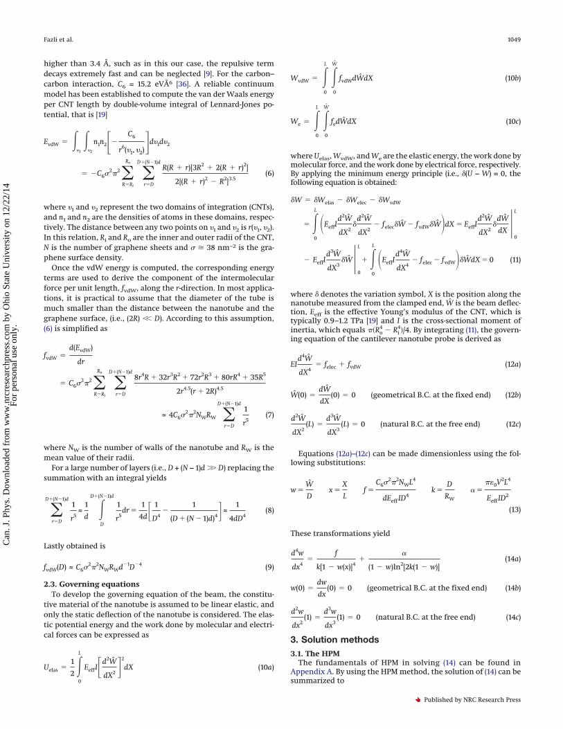
higher than 3.4 Å, such as in this our case, the repulsive termdecays extremely fast and can be neglected [9]. For the carbon–carbon interaction, C6 = 15.2 eVÅ6 [36]. A reliable continuummodel has been established to compute the van der Waals energyper CNT length by double-volume integral of Lennard-Jones po-tential, that is [19]
EvdW � ��1
��2
n1n2��C6
r6(�1, �2)�d�1d�2
� �C62�2�R�Ri
Ro
�r�D
D�(N�1)dR(R � r)[3R2 � 2(R � r)2]
2[(R � r)2 � R2]3.5(6)
where �1 and �2 represent the two domains of integration (CNTs),and n1 and n2 are the densities of atoms in these domains, respec-tively. The distance between any two points on �1 and �2 is r(�1, �2).In this relation, Ri and Ro are the inner and outer radii of the CNT,N is the number of graphene sheets and � 38 nm−2 is the gra-phene surface density.
Once the vdW energy is computed, the corresponding energyterms are used to derive the component of the intermolecularforce per unit length, fvdW, along the r-direction. In most applica-tions, it is practical to assume that the diameter of the tube ismuch smaller than the distance between the nanotube and thegraphene surface, (i.e., (2R) �� D). According to this assumption,(6) is simplified as
fvdW �d(EvdW)
dr
� C62�2�R�Ri
Ro
�r�D
D�(N�1)d8r4R � 32r3R2 � 72r2R3 � 80rR4 � 35R5
2r4.5(r � 2R)4.5
≈ 4C62�2NWRW �r�D
D�(N�1)d1
r5(7)
where NW is the number of walls of the nanotube and RW is themean value of their radii.
For a large number of layers (i.e., D + (N − 1)d �� D) replacing thesummation with an integral yields
�r�D
D�(N�1)d1
r5≈
1
d�D
D�(N�1)d
1
r5dr �
1
4d� 1
D4�
1
(D � (N � 1)d)4�≈
1
4dD4(8)
Lastly obtained is
fvdW(D) ≈ C62�2NWRWd�1D�4 (9)
2.3. Governing equationsTo develop the governing equation of the beam, the constitu-
tive material of the nanotube is assumed to be linear elastic, andonly the static deflection of the nanotube is considered. The elas-tic potential energy and the work done by molecular and electri-cal forces can be expressed as
Uelas �1
2�0
L
EeffI�d2W
dX2 �2
dX (10a)
WvdW � �0
L
�0
W
fvdWdWdX (10b)
We � �0
L
�0
W
fedWdX (10c)
where Uelas, WvdW, and We are the elastic energy, the work done bymolecular force, and the work done by electrical force, respectively.By applying the minimum energy principle (i.e., (U − W) = 0, thefollowing equation is obtained:
W � Welas � Welec � WvdW
� �0
L
�EeffId2W
dX2
d2W
dX2� felecW � fvdWWdX � EeffI
d2W
dX2
dW
dX 0
L
� EeffId3W
dX3W
0
L
� �0
L
�EeffId4W
dX4� felec � fvdWWdX � 0 (11)
where denotes the variation symbol, X is the position along thenanotube measured from the clamped end, W is the beam deflec-tion, Eeff is the effective Young’s modulus of the CNT, which istypically 0.9–1.2 TPa [19] and I is the cross-sectional moment ofinertia, which equals ��Ro
4 � Ri4�/4. By integrating (11), the govern-
ing equation of the cantilever nanotube probe is derived as
EId4W
dX4� felec � fvdW (12a)
W(0) �dW
dX(0) � 0 (geometrical B.C. at the fixed end) (12b)
d2W
dX2(L) �
d3W
dX3(L) � 0 (natural B.C. at the free end) (12c)
Equations (12a)–(12c) can be made dimensionless using the fol-lowing substitutions:
w �W
Dx �
X
Lf �
C62�2NWL4
dEeff ID4
k �D
RW
� ���0V2L4
Eeff ID2
(13)
These transformations yield
d4w
dx4�
f
k[1 � w(x)]4�
�
(1 � w)ln2[2k(1 � w)](14a)
w(0) �dw
dx(0) � 0 (geometrical B.C. at the fixed end) (14b)
d2w
dx2(1) �
d3w
dx3(1) � 0 (natural B.C. at the free end) (14c)
3. Solution methods3.1. The HPM
The fundamentals of HPM in solving (14) can be found inAppendix A. By using the HPM method, the solution of (14) can besummarized to
Fazli et al. 1049
Published by NRC Research Press
Can
. J. P
hys.
Dow
nloa
ded
from
ww
w.n
rcre
sear
chpr
ess.
com
by
Ohi
o St
ate
Uni
vers
ity o
n 12
/22/
14Fo
r pe
rson
al u
se o
nly.

w(x) � �Ax2
2!� B
x3
3!� � f
k�
�
ln2(2k)x4
4!� �4f
k�
�
ln2(2k)�
2�
ln3(2k)A
x6
6!� �4f
k�
�
ln2(2k)�
2�
ln3(2k)B
x7
7!
� �� f
k�
�
ln2(2k)�4f
k�
�
ln2(2k)�
2�
ln3(2k)�6A2�10f
k�
�
ln2(2k)�
3�
2ln3(2k)�
3�
ln4(2k)�x8
8!� … (15)
where the constants A and B can be determined by solving the resulting algebraic equation from the B.C. at x = 1 (i.e., using (14b)). Thissolution led to two different read values for A and B, in this paper we only discus the stable values of results (see Appendix B). For anygiven values of f, �, and k, (15) can be used to obtain the pull-in parameters of the CNT probe. The instability in (15) occurs whend�(x = 1)/dw ¡ 0. The pull-in voltage of the system can be determined by plotting the coordinates u versus �.
3.2. The ADMThe basic idea of the ADM is explained in ref. 37. To apply the ADM, the boundary value problem is solved using an infinite
converged series. The details of the method and mathematical computations are explained in Appendix C. Briefly, the analyticalADM solution of (14) can be obtained as the following formula:
w(x) � �Ax2
2!� B
x3
3!� � f
k�
�
ln2(2k)x4
4!� �4f
k�
�
ln2(2k)�
2�
ln3(2k)A
x6
6!� �4f
k�
�
ln2(2k)�
2�
ln3(2k)B
x7
7!�
1
8!�� f
k�
�
ln2(2k)
× �4f
k�
�
ln2(2k)�
2�
ln3(2k)B � 6A�10f
k�
�
ln2(2k)�
3�
ln3(2k)�
3�
ln4(2k)�x8 � 20�10f
k�
�
ln2(2k)�
3�
ln3(2k)�
3�
ln4(2k)AB
x9
9!� … (16)
where the constants A and B can be determined by solving theresulting algebraic equation from the B.C. at x = 1 (i.e., using (14b)).This solution led to two different read values for A and B, in thispaper we only discuss the stable values of results (see Appendix B).For any given values of f, �, and k, (16) can be used to obtain thepull-in parameters of the nanotube. The instability in (16) occurswhen d�(x = 1)/dw ¡ 0. The pull-in voltage of the system can bedetermined by plotting the coordinates u versus �.
3.3. FDMTo validate the results of the analytical solutions, a procedure
based on FDM is developed in this study for making meaningfulcomparisons (see Appendix D for the details). Following the stan-dard FDM procedure, the beam is discretized into n equal sections(elements) separated by (n + 1) nodes. By discretizing the governingdifferential equation for each element and incorporating the bound-ary conditions, an algebraic system of equations is obtained as
Aw � F (17)
where w, F, and A are displacement vector, force vector, and thestiffness matrix, respectively. By numerically solving the alge-braic system of equations, the nodal deflections of the CNT arecomputed. When the instability occurs, no solution exists for (17)and the pull-in parameters of the system can be determined byplotting the CNT tip deflection versus the applied force.
4. Results and discussionIn this section, we first examine the accuracy of the present
model for simulating the instability of CNT probe by comparingour theoretical results with the experimental ones reported in theliterature. Furthermore we discuss the obtained results from theviewpoint of the forces acting on the device.
4.1. Comparison with experimentIn ref. 7 the pull-in instability voltage of CNT probe is evaluated
experimentally. To verify the computed values, the pull-in voltageof the cantilever CNT probe with the following parameters wascompared to experimental data in Table 1. The length of the nano-tube is L = 6.8 �m, the initial gap between the nanotube andelectrode is D = 3 �m, and the radius and modulus of CNT areRw = 5 nm and E = 1 TPa, respectively. As shown, the theoreticalresults are in good agreement with the experimental data. From
the experiments, the pull-in occurs at 48 V. Numerical method(FDM) predicts the value of 49.79 V for snap down voltage of thesystem. This parameter is analytically computed as 48.36 and50.40 using HPM and ADM, respectively for the mentioned probegeometry.
4.2. CNT deflection and pull-in instabilityFigure 2 shows the centerline deflection (wtip) of a typical CNT
probe–actuator (k = 10) for different voltage values considering thevdW intermolecular force (f = 5). By increasing the external volt-age from zero to its critical value (pull-in voltage), the tip displace-ment is increased to the final stable deflection (pull-in deflection).This figure shows that the CNT have an initial deflection evenwhen no voltage differential applied. This is because of the pres-ence of molecular vdW force.
Figure 2 shows that the ADM results are closer to FDM numer-ical solution and are more accurate than HPM results. The relativeerror of analytical methods with respect to the numerical solutionis within the acceptable range for most engineering applicationsand can be reduced by selecting more series terms.
The relations between the applied voltage and centerline tipdeflection are presented in Fig. 3 for various k values. As seen,increasing the voltage difference between CNT and the ground,results in increasing the CNT displacement. When the appliedvoltage exceeds its critical value, VPI, then no solution exists forwtip and the pull-in instability occurs. Note that the operationdistance of the CNT probe–actuator is limited by this instability. Itshould be mentioned that the intersections of the curves with thehorizontal axis correspond to the initial tip deflection of CNTinduced by the presence of vdW attraction.
4.3. Probe at microdistancesFor microscale gap, the Coulomb force is dominant and vdW
attraction can be neglected because of the large distance betweenthe CNT and ground. If the distance between the CNT and groundis of the order of few micrometres, the presence of vdW force canbe neglected.
Figure 4a shows the variation of centerline dimensionless dis-placement of typical CNT (k = 100) for different applied voltagevalues neglecting the vdW force. Variation of dimensionless tipdeflection of the arms (wtip) as a function of the voltage parameter(�) is presented in Fig. 4b. By increasing the external voltage, thetip displacement is increased until the voltage exceeds its criticalvalue, �PI, and instability occurs. Note that as seen in Fig. 4c, the
1050 Can. J. Phys. Vol. 92, 2014
Published by NRC Research Press
Can
. J. P
hys.
Dow
nloa
ded
from
ww
w.n
rcre
sear
chpr
ess.
com
by
Ohi
o St
ate
Uni
vers
ity o
n 12
/22/
14Fo
r pe
rson
al u
se o
nly.
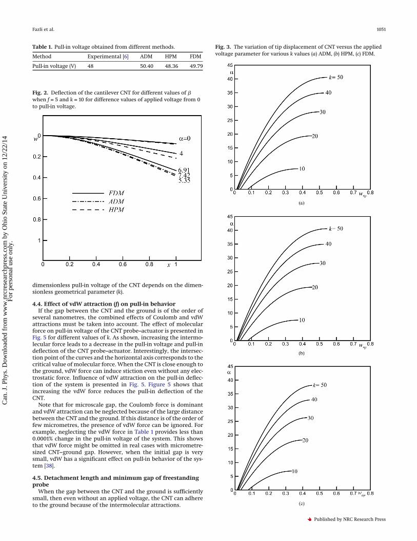
dimensionless pull-in voltage of the CNT depends on the dimen-sionless geometrical parameter (k).
4.4. Effect of vdW attraction (f) on pull-in behaviorIf the gap between the CNT and the ground is of the order of
several nanometres, the combined effects of Coulomb and vdWattractions must be taken into account. The effect of molecularforce on pull-in voltage of the CNT probe–actuator is presented inFig. 5 for different values of k. As shown, increasing the intermo-lecular force leads to a decrease in the pull-in voltage and pull-indeflection of the CNT probe–actuator. Interestingly, the intersec-tion point of the curves and the horizontal axis corresponds to thecritical value of molecular force. When the CNT is close enough tothe ground, vdW force can induce stiction even without any elec-trostatic force. Influence of vdW attraction on the pull-in deflec-tion of the system is presented in Fig. 5. Figure 5 shows thatincreasing the vdW force reduces the pull-in deflection of theCNT.
Note that for microscale gap, the Coulomb force is dominantand vdW attraction can be neglected because of the large distancebetween the CNT and the ground. If this distance is of the order offew micrometres, the presence of vdW force can be ignored. Forexample, neglecting the vdW force in Table 1 provides less than0.0001% change in the pull-in voltage of the system. This showsthat vdW force might be omitted in real cases with micrometre-sized CNT–ground gap. However, when the initial gap is verysmall, vdW has a significant effect on pull-in behavior of the sys-tem [38].
4.5. Detachment length and minimum gap of freestandingprobe
When the gap between the CNT and the ground is sufficientlysmall, then even without an applied voltage, the CNT can adhereto the ground because of the intermolecular attractions.
Table 1. Pull-in voltage obtained from different methods.
Method Experimental [6] ADM HPM FDM
Pull-in voltage (V) 48 50.40 48.36 49.79
Fig. 2. Deflection of the cantilever CNT for different values of when f = 5 and k = 10 for difference values of applied voltage from 0to pull-in voltage.
Fig. 3. The variation of tip displacement of CNT versus the appliedvoltage parameter for various k values (a) ADM, (b) HPM, (c) FDM.
Fazli et al. 1051
Published by NRC Research Press
Can
. J. P
hys.
Dow
nloa
ded
from
ww
w.n
rcre
sear
chpr
ess.
com
by
Ohi
o St
ate
Uni
vers
ity o
n 12
/22/
14Fo
r pe
rson
al u
se o
nly.

The maximum length of the CNT, Lmax, at which the CNT doesnot stick to the substrate without the application of a voltagedifference is called the detachment length [8, 14, 23, 38]. The de-tachment length is the maximum permissible length of the free-standing CNT. On the other hand, if the length of the CNT isknown, there is a minimum gap, Dmin, which prevents stictionbecause of the vdW forces. The Lmax and Dmin are very importantfor reliable operation of CNT probe–actuator and can be deter-mined from the critical value of vdW force. The critical values ofvdW force, f *, and the corresponding CNT critical tip deflection,wtip
PI , can be acquired by setting � = 0 and then plotting w(x = 1)versus f/k. Substituting f * into the definition of f in (13), we cancalculate the values of Lmax and Dmin. Table 2 shows the compar-ison between the Lmax and Dmin values obtained by various meth-
Fig. 4. Behavior of micro-switch–actuator. (a) CNT deflection fordifference values of applied voltage from 0 to pull-in voltage. (b) Tipdisplacement of CNT versus the applied voltage parameter fork = 100. (c) Effect of k values on pull-in voltage.
Fig. 5. Effect of the vdW force, f, on pull-in voltage, �PI, for k = (a) 10and (b) 50.
1052 Can. J. Phys. Vol. 92, 2014
Published by NRC Research Press
Can
. J. P
hys.
Dow
nloa
ded
from
ww
w.n
rcre
sear
chpr
ess.
com
by
Ohi
o St
ate
Uni
vers
ity o
n 12
/22/
14Fo
r pe
rson
al u
se o
nly.
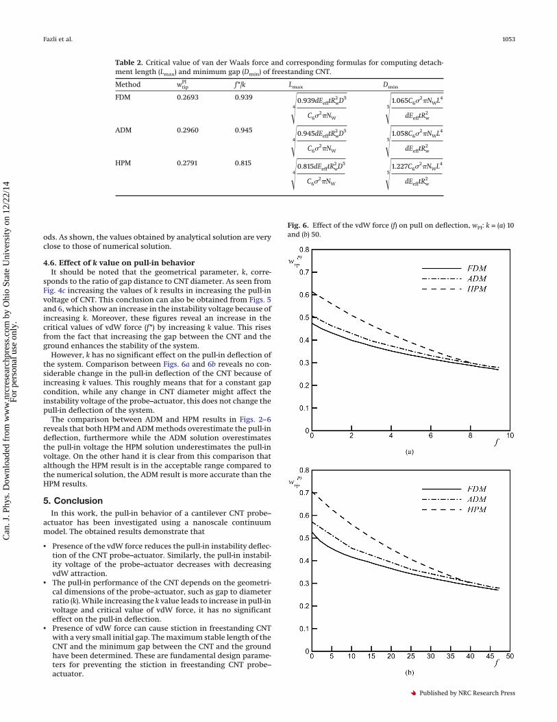
ods. As shown, the values obtained by analytical solution are veryclose to those of numerical solution.
4.6. Effect of k value on pull-in behaviorIt should be noted that the geometrical parameter, k, corre-
sponds to the ratio of gap distance to CNT diameter. As seen fromFig. 4c increasing the values of k results in increasing the pull-involtage of CNT. This conclusion can also be obtained from Figs. 5and 6, which show an increase in the instability voltage because ofincreasing k. Moreover, these figures reveal an increase in thecritical values of vdW force (f *) by increasing k value. This risesfrom the fact that increasing the gap between the CNT and theground enhances the stability of the system.
However, k has no significant effect on the pull-in deflection ofthe system. Comparison between Figs. 6a and 6b reveals no con-siderable change in the pull-in deflection of the CNT because ofincreasing k values. This roughly means that for a constant gapcondition, while any change in CNT diameter might affect theinstability voltage of the probe–actuator, this does not change thepull-in deflection of the system.
The comparison between ADM and HPM results in Figs. 2–6reveals that both HPM and ADM methods overestimate the pull-indeflection, furthermore while the ADM solution overestimatesthe pull-in voltage the HPM solution underestimates the pull-involtage. On the other hand it is clear from this comparison thatalthough the HPM result is in the acceptable range compared tothe numerical solution, the ADM result is more accurate than theHPM results.
5. ConclusionIn this work, the pull-in behavior of a cantilever CNT probe–
actuator has been investigated using a nanoscale continuummodel. The obtained results demonstrate that
• Presence of the vdW force reduces the pull-in instability deflec-tion of the CNT probe–actuator. Similarly, the pull-in instabil-ity voltage of the probe–actuator decreases with decreasingvdW attraction.
• The pull-in performance of the CNT depends on the geometri-cal dimensions of the probe–actuator, such as gap to diameterratio (k). While increasing the k value leads to increase in pull-involtage and critical value of vdW force, it has no significanteffect on the pull-in deflection.
• Presence of vdW force can cause stiction in freestanding CNTwith a very small initial gap. The maximum stable length of theCNT and the minimum gap between the CNT and the groundhave been determined. These are fundamental design parame-ters for preventing the stiction in freestanding CNT probe–actuator.
Table 2. Critical value of van der Waals force and corresponding formulas for computing detach-ment length (Lmax) and minimum gap (Dmin) of freestanding CNT.
Method wtipPI f */k Lmax Dmin
FDM 0.2693 0.939
4 0.939dEefftRw2 D5
C62�NW 5 1.065C62�NWL4
dEefftRw2
ADM 0.2960 0.945
4 0.945dEefftRw2 D5
C62�NW 5 1.058C62�NWL4
dEefftRw2
HPM 0.2791 0.815
4 0.815dEefftRw2 D5
C62�NW 5 1.227C62�NWL4
dEefftRw2
Fig. 6. Effect of the vdW force (f) on pull on deflection, wPI: k = (a) 10and (b) 50.
Fazli et al. 1053
Published by NRC Research Press
Can
. J. P
hys.
Dow
nloa
ded
from
ww
w.n
rcre
sear
chpr
ess.
com
by
Ohi
o St
ate
Uni
vers
ity o
n 12
/22/
14Fo
r pe
rson
al u
se o
nly.
• While ADM overestimates the instability voltage in comparisonwith FDM, the HPM underestimates the pull-in voltage. How-ever, both these analytical methods overestimate the pull-indeflection of the system. In comparison with HPM, ADM resultsare closer to the FDM numerical solution. Moreover it is foundthat the results of the proposed model are in a good agreementwith the experimental results reported in the literature.
References1. C. Li, E.T. Thostenson, and T.W. Chou. Compos. Sci. Technol. 68, 1227 (2008).
doi:10.1016/j.compscitech.2008.01.006.2. S. Akita. Appl. Phys. Lett. 79, 1591 (2001).3. Y. Cao, Y. Liang, S. Dong, and Y. Wang. Ultramicroscopy, 103, 103 (2005).
doi:10.1016/j.ultramic.2004.10.007. PMID:15774271.4. G.W. Wang, Y. Zhang, Y.P. Zhao, and G.T. Yang. J. Micromech. Microeng. 14,
1119 (2004). doi:10.1088/0960-1317/14/8/001.5. M. Paradise and T. Goswami. Mater. Des. 28, 1477 (2007). doi:10.1016/j.matdes.
2006.03.008.6. R.H. Baughman, C. Cui, A.A. Zakhidov, Z. Iqbal, J.N. Barisci, G.M. Spinks,
G.G. Wallace, A. Mazzoldi, D.D. Rossi, A.G. Rinzler, O. Jaschinski, S. Roth, andM. Kertesz. Science, 284, 1340 (1999). doi:10.1126/science.284.5418.1340.PMID:10334985.
7. C.H. Ke, N. Pugno, B. Peng, and H.D. Espinosa. J. Mech. Phys. Solids, 53, 1314(2005). doi:10.1016/j.jmps.2005.01.007.
8. W.H. Lin and Y.P. Zhao. Chinese Phys. Lett. 20, 2070 (2003). doi:10.1088/0256-307X/20/11/049.
9. A.M.K. Esawi and M.M. Farag. Mater. Des. 28, 2394 (2007). doi:10.1016/j.matdes.2006.09.022.
10. M. Moghimi and M.T. Ahmadian. Mech. Res. Commun. 36, 851 (2009). doi:10.1016/j.mechrescom.2009.03.004.
11. E.S. Snow, P.M. Campbell, and J.P. Novak. J. Vac. Sci. Technol. B, 20, 822(2002). doi:10.1116/1.1469017.
12. N. Jalili and K. Laxminarayana. Mechatronics, 14, 907 (2004). doi:10.1016/j.mechatronics.2004.04.005.
13. E.S. Snow, P.M. Campbell, and J.P. Novak. Appl. Phys. Lett. 80, 2002 (2002).doi:10.1063/1.1461073.
14. W.H. Lin and Y.P. Zhao. Microsyst. Technol. 11, 80 (2005). doi:10.1007/s00542-004-0411-6.
15. M. Abadyan, A. Novinzadeh, and A.S. Kazemi. Phys. Scr. 81, 015891 (2010).16. A. Koochi, A. Noghrehabadi, M. Abadyan, and E. Roohi. Int. J. Modern Phys.
B, 25, 3965 (2011). doi:10.1142/S0217979211102083.17. A. Koochi, A.S. Kazem, A. Noghrehabadi, A. Yekrangi, and M. Abadyan. Ma-
ter. Des. 32, 2949 (2011). doi:10.1016/j.matdes.2010.08.002.18. J.L. Tsai and J.F. Tu. Mater. Des. 31, 194 (2010). doi:10.1016/j.matdes.2009.06.
032.19. K.I. Tserpes. Mater. Des. 28, 2197 (2007). doi:10.1016/j.matdes.2006.07.002.20. M. Desquenes, S.V. Rotkin, and N.R. Alaru. Nanotechnology, 13, 120 (2002).
doi:10.1088/0957-4484/13/1/325.21. R.C. Batra and A. Int. J. Solids Struc. 44, 7577 (2007). doi:10.1016/j.ijsolstr.2007.
04.029.22. S.S. Gupta and R.C. Batra. Comput. Mater. Sci. 43, 715 (2008). doi:10.1016/j.
commatsci.2008.01.032.23. W.H. Lin and Y.P. Zhao. Chaos Solitons Fractals, 23, 1777 (2005). doi:10.1016/
j.chaos.2004.07.007, 10.1016/S0960-0779(04)00442-4.24. R. Soroush, A. Koochi, A.S. Kazemi, and M. Abadyan. Int. J. Struc. Stab. Dyn.
12, 1250036 (2012). doi:10.1142/S0219455412500368.25. A. Koochi, A.S. Kazemi, Y. Tadi Beni, A. Yekrangid, and M. Abadyan. Physica
E, 43, 625 (2010). doi:10.1016/j.physe.2010.10.009.26. J.S. Duan, R. Rach, and A.M. Wazwaz. Int. J. Non-Linear Mech. 49, 159 (2013).
doi:10.1016/j.ijnonlinmec.2012.10.003.27. A.M. Wazwaz, R. Rach, and J.S. Duan. Appl. Math. Comput. 219, 5004 (2013).
doi:10.1016/j.amc.2012.11.012.28. J.S. Duan and R. Rach. Appl. Math. Comput. 218, 2810 (2011). doi:10.1016/j.
amc.2011.08.024.29. D. Lesnic. Chaos Solitons Fractals, 28, 776 (2006). doi:10.1016/j.chaos.2005.08.
003.30. M. Mojahedi, M. Moghimi Zand, and M.T. Ahmadian. Appl. Math. Model. 34,
1032 (2010). doi:10.1016/j.apm.2009.07.013.31. M. Moghimi Zand, M.T. Ahmadian, and B. Rashidian. J. Sound Vib. 325, 382
(2009). doi:10.1016/j.jsv.2009.03.023.32. M. Bayat, I. Pakarand, and M. Bayat. Latin American J. Solids Struct. 8, 149
(2011).33. M.I. Pakar and G. Domairry. Latin American J. Solids Struct. 9, 145 (2012).34. W.H. Hayt and J.A. Buck. Engineering Electromagnetics, 6th ed. McGraw-
Hill, New York. 2001.35. J.E. Lennard-Jones. Proc. R. Soc. A, 129, 598 (1930). doi:10.1098/rspa.1930.0177.36. L.A. Girifalco, M. Hodak, and R.S. Lee. Phys. Rev. B, 62, 13104 (2000). doi:10.
1103/PhysRevB.62.13104.37. E. Momoniat, T.A. Selway, and K. Jina. Nonlinear Anal. 66, 2315 (2007). doi:
10.1016/j.na.2006.03.021.
38. A. Koochi, A.S. Kazemi, and M. Abadyan. Nano, 6, 419 (2011). doi:10.1142/S1793292011002731.
39. J.H. He. Int. J. Non-Linear Mech. 35, 37 (2000). doi:10.1016/S0020-7462(98)00085-7.
40. S. Guellal and Y. Cherruault. Int. J. Bio-Medical Comput. 36, 223 (1994).doi:10.1016/0020-7101(94)90057-4.
41. A.H. Nayfeh, M.I. Younis, and E.M. Abdel-Rahman. Nonlinear Dyn. 41, 211(2005). doi:10.1007/s11071-005-2809-9.
42. G. Adomian. Stochastic Systems, Academic Press, London. 1983.
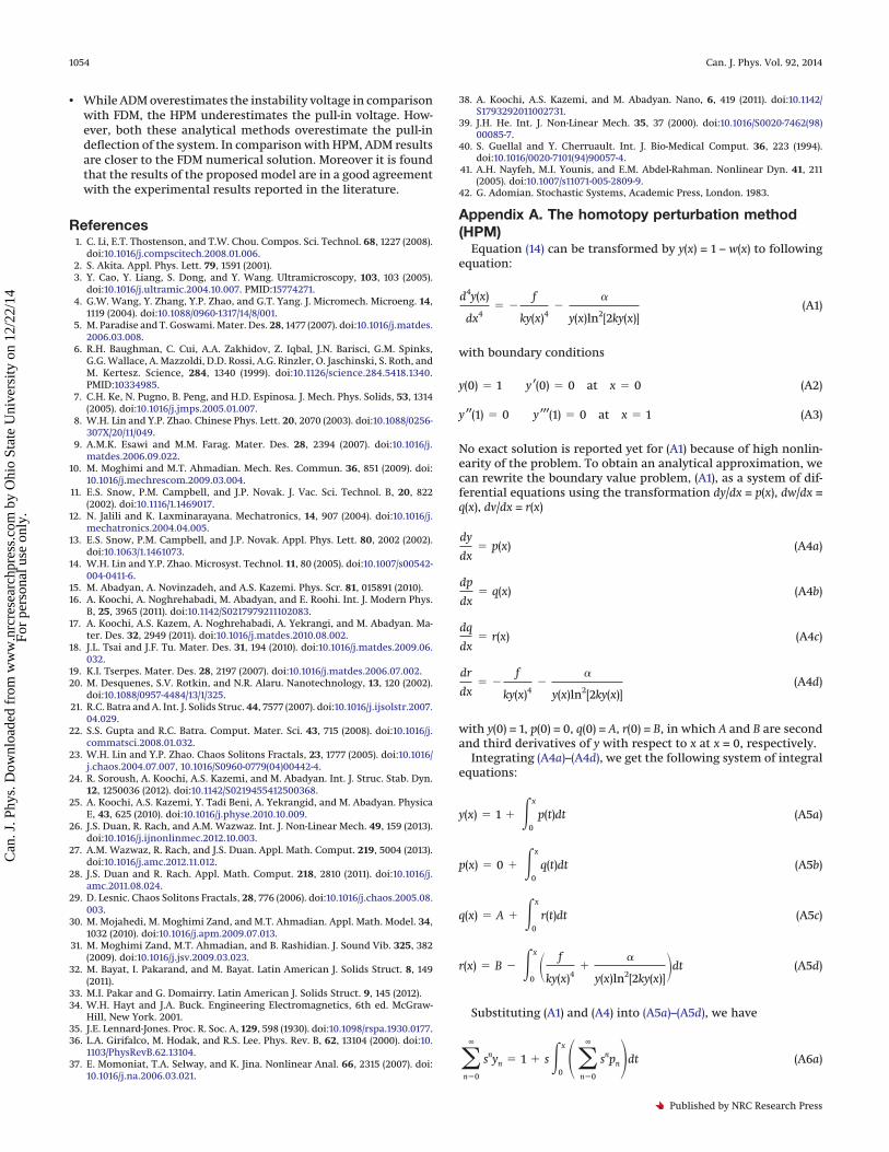
Appendix A. The homotopy perturbation method(HPM)
Equation (14) can be transformed by y(x) = 1 – w(x) to followingequation:
d4y(x)
dx4� �
f
ky(x)4�
�
y(x)ln2[2ky(x)](A1)
with boundary conditions
y(0) � 1 y ′(0) � 0 at x � 0 (A2)
y ′′(1) � 0 y ′′′(1) � 0 at x � 1 (A3)
No exact solution is reported yet for (A1) because of high nonlin-earity of the problem. To obtain an analytical approximation, wecan rewrite the boundary value problem, (A1), as a system of dif-ferential equations using the transformation dy/dx = p(x), dw/dx =q(x), dv/dx = r(x)
dy
dx� p(x) (A4a)
dp
dx� q(x) (A4b)
dq
dx� r(x) (A4c)
dr
dx� �
f
ky(x)4�
�
y(x)ln2[2ky(x)](A4d)
with y(0) = 1, p(0) = 0, q(0) = A, r(0) = B, in which A and B are secondand third derivatives of y with respect to x at x = 0, respectively.
Integrating (A4a)–(A4d), we get the following system of integralequations:
y(x) � 1 � �0
x
p(t)dt (A5a)
p(x) � 0 � �0
x
q(t)dt (A5b)
q(x) � A � �0
x
r(t)dt (A5c)
r(x) � B � �0
x � f
ky(x)4�
�
y(x)ln2[2ky(x)]dt (A5d)
Substituting (A1) and (A4) into (A5a)–(A5d), we have
�n�0
∞
snyn � 1 � s�0
x��n�0
∞
snpndt (A6a)
1054 Can. J. Phys. Vol. 92, 2014
Published by NRC Research Press
Can
. J. P
hys.
Dow
nloa
ded
from
ww
w.n
rcre
sear
chpr
ess.
com
by
Ohi
o St
ate
Uni
vers
ity o
n 12
/22/
14Fo
r pe
rson
al u
se o
nly.

�n�0
∞
snpn � 0 � s�0
x��n�0
∞
snqndt (A6b)
�k�0
∞
snqn � A � s�0
x��n�0
∞
snrndt (A6c)
�n�0
∞
snrn � B � s�0
x��n�0
∞
sn�ndt (A6d)
The functions �n approximating the nonlinear term �f/kyn4� �
��/ynln2�2kyn�� are determined in Taylor series [39]
�n �1
n!
dn
dsn��i�0
∞
si� f
kyi4
��
yiln2[2kyi]
�s�0
(A7)
Substituting (A7) into (A6a)–(A6d) and comparing the coefficient oflike powers of p in (A6a)–(A6d), we obtain
s(0) : �y0 � 1p0 � 0q0 � Ar0 � B
s(1) : �y1 � 0p1 � Axq1 � Bx
r1 � �� f
k�
�
ln2(2k)x
s(2) :
y2 � Ax2
2
p2 � Bx2
2
q2 � �� f
2k�
�
2ln2(2k)x2
r2 � 0
s(3) :
y3 � Bx3
6
p3 � �� f
6k�
�
6ln2(2k)x3
q3 � 0
r3 � �2f
3k�
�
6ln2(2k)�
�
3ln3(2k)Ax3
s(4) :
y4 � �� f
24k�
�
24ln2(2k)x4
p4 � 0
q4 � � f
6k�
�
24ln2(2k)�
�
12ln3(2k)Ax4
r4 � � f
6k�
�
24ln2(2k)�
�
12ln3(2k)Bx4
s(5) :
y5 � 0
p5 � � f
30k�
�
120ln2(2k)�
�
60ln3(2k)Ax
q5 � � f
30k�
�
120ln2(2k)�
�
60ln3(2k)Bx5
r5 � ��� f
k�
�
ln2(2k)� f
30k�
�
125ln2(2k)�
�
60ln3(2k)�� f
2k�
�
20ln2(2k)�
3�
20ln3(2k)�
3�
20ln4(2k)A2�x5
s(6) :
y6 � � f
180k�
�
720ln2(2k)�
�
360ln3(2k)Ax6
p6 � � f
180k�
�
720ln2(2k)�
�
360ln3(2k)Bx6
q6 � ��� f
k�
�
ln2(2k)� f
180k�
�
750ln2(2k)�
�
360ln3(2k)�� f
12k�
�
120ln2(2k)�
�
40ln3(2k)�
�
40ln4(2k)A2�x6
…
s(7) : �y7 � � f
1260k�
�
5040ln2(2k)�
�
2520ln3(2k)Bx7
p7 � ��� f
k�
�
ln2(2k)� f
1260k�
�
5040ln2(2k)�
�
2520ln3(2k) � � f
84k�
�
840ln2(2k)�
�
280ln3(2k)�
�
280ln4(2k)A2�x7
…
s(8) :�y8 � ��� f
k�
�
ln2(2k)� f
10080k�
�
40320ln2(2k)�
�
20160ln3(2k) � � f
672k�
�
6720ln2(2k)�
�
2240ln3(2k)�
�
2240ln4(2k)A2�x8
…
…. : {… (A8)
Fazli et al. 1055
Published by NRC Research Press
Can
. J. P
hys.
Dow
nloa
ded
from
ww
w.n
rcre
sear
chpr
ess.
com
by
Ohi
o St
ate
Uni
vers
ity o
n 12
/22/
14Fo
r pe
rson
al u
se o
nly.
Appendix B. Considerations concerned with pull-inbehavior
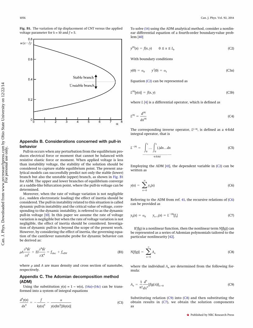
Pull-in occurs when any perturbation from the equilibrium pro-duces electrical force or moment that cannot be balanced withresistive elastic force or moment. When applied voltage is lessthan instability voltage, the stability of the solution should beconsidered to capture stable equilibrium point. The present ana-lytical models can successfully predict not only the stable (lower)branch but also the unstable (upper) branch, as shown in Fig. B1for ADM. The upper and lower branches of equilibrium convergeat a saddle-like bifurcation point, where the pull-in voltage can bedetermined.
Moreover, when the rate of voltage variation is not negligible(i.e., sudden electrostatic loading) the effect of inertia should beconsidered. The pull-in instability related to this situation is calleddynamic pull-in instability and the critical value of voltage, corre-sponding to the dynamic instability, is referred to as the dynamicpull-in voltage [10]. In this paper we assume the rate of voltagevariation is negligible but when the rate of voltage variation is notnegligible, the effect of inertia should be considered. Investiga-tion of dynamic pull-in is beyond the scope of the present work.However, by considering the effect of inertia, the governing equa-tion of the cantilever nanotube probe for dynamic behavior canbe derived as:
�A�2W
�t2� EI
�4W
�X4� felec � fvdW (B1)
where � and A are mass density and cross section of nanotube,respectively.
Appendix C. The Adomian decomposition method(ADM)
Using the substitution y(x) = 1 − w(x), (14a)–(14c) can be trans-formed into a system of integral equations
d4y(x)
dx4� �
f
ky(x)4�
�
y(x)ln2[2ky(x)](C1)
To solve (14) using the ADM analytical method, consider a nonlin-ear differential equation of a fourth-order boundary-value prob-lem [40]
y(4)(x) � f(x, y) 0 ≤ x ≤ Lb (C2)
With boundary conditions
y(0) � �0 y ′(0) � �1 (C3a)
Equation (C2) can be represented as
L(4)[y(x)] � f(x, y) (C3b)
where L [4] is a differential operator, which is defined as
L(4) �d(4)
dx(4)(C4)
The corresponding inverse operator, L(−4), is defined as a 4-foldintegral operator, that is
L�(4) � �0
x
…�0
x
(.)dx…dx
Ç
4-fold
(C5)
Employing the ADM [41], the dependent variable in (C2) can bewritten as
y(x) � �n�0
∞
yn(x) (C6)
Referring to the ADM from ref. 41, the recursive relations of (C6)can be provided as
y0(x) � �0 yn�1(x) � L�(4)[fk] (C7)
If f(g) is a nonlinear function, then the nonlinear term N[f(g)] canbe represented as a series of Adomian polynomials tailored to theparticular nonlinearity [42].
N[f(g)] � �n�0
∞
An (C8)
where the individual An are determined from the following for-mula:
An �1
n!
dn
d�n[f(g(�))]��0 (C9)
Substituting relation (C9) into (C8) and then substituting theobtain results in (C7), we obtain the solution componentsas
Fig. B1. The variation of tip displacement of CNT versus the appliedvoltage parameter for k = 10 and f = 5.
1056 Can. J. Phys. Vol. 92, 2014
Published by NRC Research Press
Can
. J. P
hys.
Dow
nloa
ded
from
ww
w.n
rcre
sear
chpr
ess.
com
by
Ohi
o St
ate
Uni
vers
ity o
n 12
/22/
14Fo
r pe
rson
al u
se o
nly.

y0 � 1 y1 �1
2!C1x
2 �1
3!C2x
3 �1
4!� f
k�
�
ln2(2k)x4
y2 �1
6!�4f
k�
�
ln2(2k)�
2�
ln3(2k)C1x
6 �1
7!�4f
k�
�
ln2(2k)�
2�
ln3(2k)C2x
7 �1
8!� f
k�
�
ln2(2k)�4f
K�
�
ln2(2k)�
2�
ln3(2k)C2x
8
y3 � �1
8!�60f
k�
6�
ln2(2k)�1 �
3
ln(2k)�
3
ln2(2k)�C1
2x8 �1
9!�200f
k�
20�
ln2(2k)�1 �
3
ln(2k)�
3
ln2(2k)�C1C2x
9
�1
10!�60�� f
2k�
�
2ln2(2k)C1 �
C22
3��10f
k�
�
ln2(2k)�1 �
3
ln(2k)�
3
ln2(2k)� � �4f
k�
�
ln2(2k)�
2�
ln3(2k)2�x10
�1
11!�70� f
k�
�
ln2(2k)�10f
K�
�
ln2(2k)�1 �
3
ln(2k)�
3
ln2(2k)� � �4f
K�
�
ln2(2k)�
2�
ln3(2k)2�C2x
11
�1
12!�� f
k�
ln2(2k)�4f
K�
ln2(2k)�
2
ln3(2k)2
� 840�10f
k�
ln2(2k)�1 �
3
ln(2k)�
3
ln2(2k)��4f
k�
ln2(2k)�
2
ln3(2k)2�x12
Ê
(C10)
Appendix D. Finite difference method (FDM)To solve the governing equation using FDM, the beam is dis-
cretized into n equal elements separated by n + 1 nodes. For eachelement, the governing equation, (14), in the discretized form canbe written as
ui�2 � 4ui�1 � 6ui � 4ui�1 � ui�2
�x4� Fi (D1)
where �x is the grid spacing, ui is the deflection of ith grid and
Fi �f
k(1 � wi)4
��
(1 � wi)ln2[2k(1 � wi)]
(D2)
Applying (D1) to all of the elements and incorporating the bound-ary conditions, (14b) and (14c), a matrix form system of algebraicequations is obtained as
Au � F (D3)
where u = [u1, u2, …, un]T, F = [F1, F2, …, Fn]T and A matrix can bedefined as
A � �7 �4 1 0 0 … 0 0 0 0
�4 6 �4 1 0 … 0 0 0 01 �4 6 �4 1 … 0 0 0 00 1 �4 6 �4 … 0 0 0 00 0 1 �4 6 … 0 0 0 00 0 0 1 �4 … 0 0 0 0É É É É É Ì É É É É0 0 0 0 0 Ê �4 6 �4 10 0 0 0 0 Ê 1 �4 5 �20 0 0 0 0 Ê 0 1 �2 1
� (D4)
By numerically solving (D3), the nodal deflections that govern theoverall deflection of the CNT arms are computed.
MATLAB commercial software is employed to numerically solve(D3) for the nodal deflections that govern the overall deflection ofthe beam.
Fazli et al. 1057
Published by NRC Research Press
Can
. J. P
hys.
Dow
nloa
ded
from
ww
w.n
rcre
sear
chpr
ess.
com
by
Ohi
o St
ate
Uni
vers
ity o
n 12
/22/
14Fo
r pe
rson
al u
se o
nly.