Influence of dilution effect on the electrochemical performance of integrated 0.5Li(Mn1.5Ni0.5)O4....
21
Author's Accepted Manuscript Influence of dilution effect on the electrochemical performance of integrated 0.5Li(Mn 1.5 Ni 0.5 )O 4 . 0.5 (Li 2 MnO 3 -li(Mn 0.5 Ni 0.5 )O 2 cathodes In Hyung Choi, Jae Min Choi, Yun Ju Hwang, Vanchiappan Aravindan, Yun Sung Lee, Kee Suk Nahm PII: S0272-8842(14)00722-6 DOI: http://dx.doi.org/10.1016/j.ceramint.2014.04.167 Reference: CERI8535 To appear in: Ceramics International Received date: 28 March 2014 Revised date: 24 April 2014 Accepted date: 30 April 2014 Cite this article as: In Hyung Choi, Jae Min Choi, Yun Ju Hwang, Vanchiappan Aravindan, Yun Sung Lee, Kee Suk Nahm, Influence of dilution effect on the electrochemical performance of integrated 0.5Li(Mn 1.5 Ni 0.5 )O 4 . 0.5(Li 2 MnO 3 -li (Mn 0.5 Ni 0.5 )O 2 cathodes, Ceramics International, http://dx.doi.org/10.1016/j.cera- mint.2014.04.167 This is a PDF file of an unedited manuscript that has been accepted for publication. As a service to our customers we are providing this early version of the manuscript. The manuscript will undergo copyediting, typesetting, and review of the resulting galley proof before it is published in its final citable form. Please note that during the production process errors may be discovered which could affect the content, and all legal disclaimers that apply to the journal pertain. www.elsevier.com/locate/ceramint
Transcript of Influence of dilution effect on the electrochemical performance of integrated 0.5Li(Mn1.5Ni0.5)O4....

Author's Accepted Manuscript
Influence of dilution effect on the electrochemicalperformance of integrated 0.5Li(Mn1.5Ni0.5)O4. 0.5(Li2MnO3-li(Mn0.5Ni0.5)O2 cathodes
In Hyung Choi, Jae Min Choi, Yun Ju Hwang,Vanchiappan Aravindan, Yun Sung Lee, Kee SukNahm
PII: S0272-8842(14)00722-6DOI: http://dx.doi.org/10.1016/j.ceramint.2014.04.167Reference: CERI8535
To appear in: Ceramics International
Received date: 28 March 2014Revised date: 24 April 2014Accepted date: 30 April 2014
Cite this article as: In Hyung Choi, Jae Min Choi, Yun Ju Hwang, VanchiappanAravindan, Yun Sung Lee, Kee Suk Nahm, Influence of dilution effect on theelectrochemical performance of integrated 0.5Li(Mn1.5Ni0.5)O4. 0.5(Li2MnO3-li(Mn0.5Ni0.5)O2 cathodes, Ceramics International, http://dx.doi.org/10.1016/j.cera-mint.2014.04.167
This is a PDF file of an unedited manuscript that has been accepted for publication. As aservice to our customers we are providing this early version of the manuscript. Themanuscript will undergo copyediting, typesetting, and review of the resulting galley proofbefore it is published in its final citable form. Please note that during the production processerrors may be discovered which could affect the content, and all legal disclaimers that applyto the journal pertain.
www.elsevier.com/locate/ceramint

1
Influence of dilution effect on the electrochemical performance of
integrated 0.5Li(Mn1.5Ni0.5)O4 . 0.5(Li2MnO3-Li(Mn0.5Ni0.5)O2 cathodes
In Hyung Choia, Jae Min Choia, Yun Ju Hwangb, Vanchiappan Aravindand, Yun Sung
Leee,* Kee Suk Nahma,b,c*
aDepartment of Energy Storage and Conversion Engineering, bR&D Education Center for Fuel
Cell Materials & Systems, and cSchool of Chemical Engineering, Chonbuk National University,
Jeon-ju 561-756, Korea
dEnergy Research Institute @ NTU (ERI@N), Nanyang Technological University, Research
Techno Plaza, 50 Nanyang Drive, Singapore 637553
eFaculty of Applied Chemical Engineering, Chonnam National University, Gwang-ju 500-757,
Korea
Abstract
We report the influence of dilution effect on the synthesis and electrochemical profiles of
integrated spinel-layered 0.5Li(Mn1.5Ni0.5)O4 . 0.5(Li2MnO3-Li(Mn0.5Ni0.5)O2 cathodes prepared
by scalable continuous stirred tank reactor (CSTR). Apparently, the dilution of chelating agent or
precursor solutions leads to the formation of unavoidable impurity phases. However, the
presence of such impurity traces certainly improves the electrochemical stability of such spinel-
* Corresponding author.
Tel : +82-63-270-2311, Fax : +82-63-270-3909, E-mail : [email protected] (K.S. Nahm)
Tel.& Fax : +82 62 530 1904, E-mail : [email protected] (Y.S. Lee)
2
layered integrated electrodes. In addition, influence of operating potential also investigated and
found that 2.4-4.8 V vs. Li is optimal condition to yield high capacity and high performance
cathode material.
Introduction
Zero emission transportation applications like hybrid electric vehicles (HEV) and electric
vehicles (EV) requires high energy density Li-ion power packs. Nevertheless, the construction of
high energy Li-ion batteries (LIB) are completely depends on the utilization of high capacity and
high voltage cathodes[1]. Unfortunately, the commercially available existing layered type
LiCoO2 is limited to 0.5 moles of Li (~137 mAh g–1) only[2]. On the other hand, native spinel
(LiMn2O4) and olivine phosphates (LiMPO4, M=Fe, Mn and Co) and its derivatives are
exhibiting the practical capacity less than 150 mAh g–1 [3]. In addition, V2O5 and orthosilicates
(Li2MSiO4, M=Fe, Mn and Co) are also considered as promising cathode with high theoretical
limitations however irreversible structural change and inferior electrochemical profiles of former
and latter counterparts renders them as “show-case” cathodes[3-6]. Mixture of two cathodes are
also one of the solutions to achieve desirable high capacity and high power cathodes for LIB
applications which has been successfully adopted for the Sony’s NEXLION configuration
(LiCoO2 + Li(Co-Ni-Mn)O2)[1]. These kinds of integrated cathodes can be prepared easily by
conventional synthesis route or simple mechanical/manual mixing of two electrode counterparts.
Apart from the capacity point of view, eco-friendliness and cost effectiveness cannot be ruled out
for such cathodes. In this line, Fe and Mn based electrodes are the choice, but richness in the
oxidation states, higher operating potential and high stability makes Mn based materials are
attractive than Fe, although having the issue of Jahn-Teller distortion[7].

3
Among the Mn based candidates, layered type Li2MnO3 (analogue of α-NaFeO2) is
exhibiting the high theoretical capacity ~459 mAh g–1 for the removal of two moles of Li [8-10].
Unfortunately, the Li2MnO3 is electrochemically inactive, hence the removal of Li is not
plausible, because the transition metal Mn is already in the 4+ state and it is impossible to
oxidize further in to 5+ state[8]. Hitherto, there are four main reasons believed for the
electrochemical activity of such layered type Li2MnO3, (i) Oxidation of Mn3+ associated with
oxygen deficiency (Li2MnO3-δ), (ii) Removal of lithium accompanied by oxygen loss (Li2O), (iii)
Oxidation of electrolyte solution and subsequent exchange of H+ for Li+ and (iv) Oxidation of
other transition-metal elements (observed only in the solid-solutions)[11, 12]. For the preparation
of integrated electrodes, the solid solution plays a vital role to determine the energy density i.e.
operating potential. Generally, the integrated electrodes comprising the formula xLi2MnO3.(1-
x)LiMO2, M=Ni, Co, M for “layered-layered” and x Li2MnO3. (1-x)LiM2O4, M=Ni, Co, Mn for
“layered-spinel”, in which Li2MnO3 translates better structural and electrochemical stability
irrespective of either layered LiMO2 or spinel LiM2O4 components for wider operating potential
[13, 14]. In addition to the native layered and spinel counterparts, the metal substituted
derivatives also investigated to improve the cycleability and electrochemical profiles. Amongst,
layered-layered electrodes are found promising in terms capacity, but the net energy density is
more or less equal to that of layered LiCoO2 only. Hence, the research focus is directed to
layered-spinel integrated cathodes, since Ni-substituted spinel (LiMn2O4) exhibits the higher
redox potential than native compound[15]. In this line we made an attempt to explore the
possibility of using high voltage and high capacity integrated electrodes (0.5Li(Mn1.5Ni0.5)O4 .
0.5(Li2MnO3-Li(Mn0.5Ni0.5)O2)) by carbonate co-precipitation technique. The extensive
structural and electrochemical profiles were evaluated and described in detail.

4
Experimental
The solid-solution composed of integrated spinel-layered type x Li(Mn1.5Ni0.5)O4 . (1-x)
[Li2MnO3-Li(Mn0.5Ni0.5)O2], where x =0.5 was prepared by carbonate co-precipitation technique
in a continuous stirred tank reactor (CSTR). All the analytical grade starting materials like
Li2CO3, Na2CO3, MnSO4, NiSO4, NH4OH were procured and used as such. The Na2CO3 solution
was used as the chelating agent to control the precipitation of the precursor. For the preparation
of layered-spinel integrated materials precursor, transition metal (Mn:Ni) ratio was fixed to 3:1.
Several synthesis parameters were used to tailor the Mn0.75Ni0.25CO3 precursor. The resultant
Mn0.75Ni0.25CO3 was filtered, washed well with distilled water and dried at 100 oC for 12 h in air
atmosphere. The desired product was yielded after reacting with appropriate amount of Li2CO3
in solid-state reaction at 650 oC for 5 h, and then fired at 900 oC for 12 h in air.
Structural properties were analyzed by X-ray diffraction (XRD) measurements using Rint
1000 Regaku, Japan equipped with Cu Kα radiation. Morphological features of the powders
were observed by field emission scanning electron microscopy. The electrochemical
characterizations were performed in CR2032 coin-cell configuration. The composite electrodes
were formulated with accurately weighed 20 mg of active material, 3 mg of conductive additive
(Ketzen black) and 3 mg of Teflonized acetylene black (TAB-2) using ethanol and pressed over
150 mm2 nickel mesh and dried at 160 oC for 4 h in vacuum oven. Test cells were fabricated with
metallic lithium which was separated by porous polypropylene separator (Celgard 3401) under
Ar filled Glove box. 1 M LiPF6 ethylene carbonate (EC)/di-methyl carbonate (DMC) (1:1 v/v)
was used as electrolyte solution. The galvanostatic charge–discharge studies were performed
between 2 – 4.9 V vs. Li at current density of 0.1 mA cm–2 (0.05 C) in ambient temperature
conditions.

5
Results and discussion
Influence of dilution of the transition metal and chelating agent was on the synthesis of mixed
carbonate studied. Precursor, Mn0.75Ni0.25CO3 have been prepared with various conditions like
inclusion of NH4OH solution (P1), large amount of chelating agent usage (P2), diluting the
chelating agent and without diluting transition metal counterparts (P3 and P4), dilution of both
transition metal solution and chelating agent (P5 and P6) in CSTR with 150-400 rpm.
Irrespective of the synthesis conditions, the precipitation of mixed transition metal carbonate was
obtained. Figure 1 represents the powder- XRD patterns of Mn0.75Ni0.25CO3 precursor prepared
with various conditions according to table 1. A trace amount of NiOOH is noted which is clearly
evident from the XRD reflections (peak observed at ~11o) along with MnCO3 content. The
prominent reflection at ~31o ensures the crystallinity of the prepared mixed carbonate[16]. This
clearly suggests the dilution of precursor or chelating agent did not influence the structural
properties of the precursor. Morphological features of the Mn0.75Ni0.25CO3 were analyzed by FE-
SEM and given in figure 2. Apparent to note that, all the resultant Mn0.75Ni0.25CO3 powders
exhibited the spherical shaped morphology, although slight variation in the particulate shape.
The breaking of the spherical shaped morphology is also noted which is mainly associated with
the high speed rotation of the blade in the CSTR. Then, the Mn0.75Ni0.25CO3 powders were
manually ground with appropriate amount of Li2CO3 to yield the desired integrated layered-
spinel phase compound by solid-state reaction.
XRD pattern of layered-spinel 0.5Li(Mn1.5Ni0.5)O4 – 0.5[Li2MnO3-Li(Mn0.5Ni0.5)O2] powder
is given in figure 3. All the XRD patterns clearly showed the strong reflections which composed
of layered, spinel and superstructure, for example the appearance of small peaks between 20o to
25o are indicates the characteristic of Li2MnO3 superstructure[17, 18]. The Li2MnO3 phase is
6
indexed according to the monoclinic structure C2/m space group in which [0 0 1] closed packed
plane is coincident with [0 0 3] plane. Generally, the superstructure formation is caused from the
short-range ordering between Li-ions and transition metal atoms in the transition metal slab. In
the present case, a clear separation of superstructure is noted which suggests the dominant
characteristic of layered type Li2MnO3. Apart from the dilution, a basic condition is necessary to
yield a single phase materials, which is clearly observed from the XRD reflections, for example a
trace amount of unknown impurity phase is observed for all the cases (P2 - P6), except NH4OH
treated one (P1). Presence of spinel phase is clearly identified from the existence of the peak at
2θ = ~37o and ~44o which corresponds to the (3 1 1) and (4 0 0) planes, respectively. On the
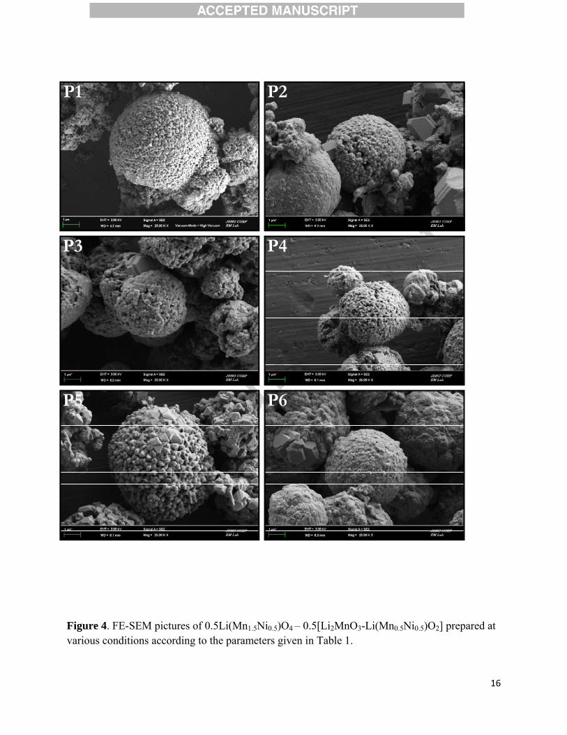
other hand, there is no much variation in the spherical shaped morphology noted compared to the
mixed carbonate precursors which is clearly supported from the FE-SEM pictures (Figure 4).
The electrochemical profiles of layered-spinel 0.5Li(Mn1.5Ni0.5)O4.0.5[Li2MnO3-
Li(Mn0.5Ni0.5)O2] were evaluated between 2-4.9 V vs. Li at current density of 0.1 mA cm–2 (0.05
C rate) in ambient temperature conditions (Figure 5). In the first charge curve is entirely different
than rest of the charge curves. During the charging, a sharp increase in potential from open
circuit voltage to ~4.5 V vs. Li is corresponds to the removal of Li from the Li(Mn0.5Ni0.5)O2
lattice by single phase reaction and it is reversible as well. The presence of slopping region
above ~4.5 V vs. Li is corresponds to the removal of Li and oxygen (net removal of Li2O) and
associated activation of layered Li2MnO3 (Li2MnO3-δ) which is an irreversible reaction. Unlike
that of charging process, several reactions are noted during the discharge reaction. A small
plateau around ~4.7 V vs. Li is corresponds to the reversible Li-insertion in to tetrahedral sites
i.e. reduction of Ni4+/2+ in spinel component (Li(Mn1.5Ni0.5)O4)[19]. The slopping region between
~4.5-2.7 V vs. Li is corresponds to the contribution of layered type counterparts like Li2MnO3-δ

7
and Li(Mn0.5Ni0.5)O2 i.e. redox reaction of Ni3+/2+ and partially Mn4+/3+. The small plateau around
~2.7 V vs. Li is attributed to the reversible Li-insertion in to octahedral sites of spinel phase
Li(Mn1.5Ni0.5)O4 in two-phase reaction mechanism i.e. reduction of Mn4+/2+ [20, 21]. The cell
(P1) delivered the reversible capacity of ~170 mAh g–1 whereas other diluted samples present the
reversible capacity of ~150 mAh g–1 only under the same current density, except P4 which
exhibits ~170 mAh g–1. Irrespective of the layered-spinel integrated electrodes, increasing
capacity profiles are noted for all the cases. Such increasing capacity profiles are common for the
case of Li2MnO3 based cathodes, which is mainly due to the slower participation of the active
material in the electrochemical reaction because of the presence of Mn4+ ions. Plot of discharge
capacity vs. cycle number is depicted in figure 6. All the materials show the increasing capacity
profile upon cycling, which is mainly attributed to the slower participation of the active
materials. Unfortunately, after certain number of cycles (10-20 cycles) the decrease in capacity
trends is noted. This decrease in capacity trends are mainly because of the cubic-tetragonal
transformation occurred in the spinel counterpart which leads to structural instability. Moreover,
the partial reduction of Mn4+ in to Mn3+ reduction in layered part and reversible insertion at ~2.7
V vs. Li (reduction of Mn4+ in to Mn3+) leads to the presence of Mn3+ ion, which is also having
the problem of Jahn-Teller distortion. As a consequence, decrease in capacity profiles is noted
for all the materials. Interestingly, except P1 all the materials rendered good electrochemical
stability, we believe such stability is mainly because of the unknown impurity. But, our aim is to
prepare the phase pure electrodes with improved electrochemical activity.
Then, we evaluated the influence of cut-off potential to improve the electrochemical profiles
of phase pure spinel-layered integrated electrodes (P1) under the same current density of 0.1 mA
cm–2 and given in figure 7 & 8. All the cases, first two cycles are performed between 2-4.9 V vs.

8
Li to activate the layered electrode Li2MnO3. Apparent to note that, improved capacity retention
is noted between 2.4-4.8 V vs. Li when compared to 2-4.9 V vs. Li, for example the integrated
spinel-layered delivered the capacity of ~135 and ~85 mAh g–1 for former and latter cut-off
potentials respectively. However, the maximum deliverable capacity has been suppressed. This
clearly suggests the 2.4-4.8 V vs. Li is optimal condition to yield high capacity cathode active
material. Further studies are in progress to improve the capacity fading during cycling.
Conclusion
We studied the dilution effect of integrated spinel-layered 0.5Li(Mn1.5Ni0.5)O4 –
0.5[Li2MnO3-Li(Mn0.5Ni0.5)O2] cathodes synthesized via CSTR. Present results clearly reveal the
dilution of either chelating agent or precursor results the formation of unwanted impurity phase
along with the desired phase. Further, influence of testing potential also validated to improve the
electrochemical stability during cycling. Amongst, testing window 2.4-4.8 V vs. Li was found
optimum to yield high capacity and high performance cathode. This preliminary result strongly
encouraging to develop such integrated spinel-layered cathodes to fabricate high energy density
Li-ion power packs for HEV and EV applications.
Acknowledgements
This research was supported by Basic Science Research Program through the National Research
Foundation of Korea (NRF) funded by the Ministry of Education(No. 2013R1A1A2012656) and
was also supported by research funds of Chonbuk National University in 2011.

9
References
[1] V. Aravindan, J. Gnanaraj, Y.-S. Lee, S. Madhavi, LiMnPO4 - A next generation cathode
material for lithium-ion batteries. Journal of Materials Chemistry A, 1 (2013) 3518-3539.
[2] Y. Nishi, The development of lithium ion secondary batteries. The Chemical Record, 1
(2001) 406-413.
[3] C. Masquelier, L. Croguennec, Polyanionic (Phosphates, Silicates, Sulfates) Frameworks as
Electrode Materials for Rechargeable Li (or Na) Batteries. Chemical Reviews, 113 (2013) 6552-
6591.
[4] V. Aravindan, K. Karthikeyan, K.S. Kang, W.S. Yoon, W.S. Kim, Y.S. Lee, Influence of
carbon towards improved lithium storage properties of Li2MnSiO4 cathodes. Journal of Materials
Chemistry, 21 (2011) 2470-2475.
[5] V. Aravindan, K. Karthikeyan, S. Ravi, S. Amaresh, W. Kim, Y. Lee, Adipic acid assisted
sol–gel synthesis of Li2MnSiO4 nanoparticles with improved lithium storage properties. Journal
of Materials Chemistry, 20 (2010) 7340-7343.
[6] V. Aravindan, K. Karthikeyan, J. Lee, S. Madhavi, Y. Lee, Synthesis and improved
electrochemical properties of Li2MnSiO4 cathodes. Journal of Physics D: Applied Physics, 44
(2011) 152001.
[7] S. Okada, J.-i. Yamaki, Iron-based Cathodes/anodes for Li-ion and Post Li-ion Batteries.
Journal of Industrial and Engineering Chemistry, 10 (2004) 1104-1113.
[8] A.D. Robertson, P.G. Bruce, The origin of electrochemical activity in Li2MnO3. Chemical
Communications, 0 (2002) 2790-2791.
[9] A.D. Robertson, P.G. Bruce, Mechanism of Electrochemical Activity in Li2MnO3.
Chemistry of Materials, 15 (2003) 1984-1992.

10
[10] P. Kalyani, S. Chitra, T. Mohan, S. Gopukumar, Lithium métal rechargeable cells using
Li2MnO3 as the positive electrode. Journal of Power Sources, 80 (1999) 103-106.
[11] K. Kubota, T. Kaneko, M. Hirayama, M. Yonemura, Y. Imanari, K. Nakane, R. Kanno,
Direct synthesis of oxygen-deficient Li2MnO3−x for high capacity lithium battery electrodes.
Journal of Power Sources, 216 (2012) 249-255.
[12] Y. Koyama, I. Tanaka, M. Nagao, R. Kanno, First-principles study on lithium removal
from Li2MnO3. Journal of Power Sources, 189 (2009) 798-801.
[13] M.M. Thackeray, S.-H. Kang, C.S. Johnson, J.T. Vaughey, R. Benedek, S.A. Hackney,
Li2MnO3-stabilized LiMO2 (M = Mn, Ni, Co) electrodes for lithium-ion batteries. Journal of
Materials Chemistry, 17 (2007) 3112-3125.
[14] N. Yabuuchi, K. Yoshii, S.-T. Myung, I. Nakai, S. Komaba, Detailed Studies of a High-
Capacity Electrode Material for Rechargeable Batteries, Li2MnO3−LiCo1/3Ni1/3Mn1/3O2. Journal
of the American Chemical Society, 133 (2011) 4404-4419.
[15] J. Cabana, S.-H. Kang, C.S. Johnson, M.M. Thackeray, C.P. Grey, Structural and
Electrochemical Characterization of Composite Layered-Spinel Electrodes Containing Ni and
Mn for Li-Ion Batteries. Journal of The Electrochemical Society, 156 (2009) A730-A736.
[16] D. Wang, I. Belharouak, G.M. Koenig, G. Zhou, K. Amine, Growth mechanism of
Ni0.3Mn0.7CO3 precursor for high capacity Li-ion battery cathodes. Journal of Materials
Chemistry, 21 (2011) 9290-9295.
[17] K. Karthikeyan, S. Amaresh, G.W. Lee, V. Aravindan, H. Kim, K.S. Kang, W.S. Kim, Y.S.
Lee, Electrochemical performance of cobalt free, Li1.2(Mn0.32Ni0.32Fe0.16)O2 cathodes for lithium
batteries. Electrochimica Acta, 68 (2012) 246-253.

11
[18] K. Karthikeyan, S. Amaresh, V. Aravindan, W.S. Kim, K.W. Nam, X.Q. Yang, Y.S. Lee,
Li(Mn1/3Ni1/3Fe1/3)O2–Polyaniline hybrids as cathode active material with ultra-fast charge–
discharge capability for lithium batteries. Journal of Power Sources, 232 (2013) 240-245.
[19] M.C. Kim, K.-W. Nam, E. Hu, X.-Q. Yang, H. Kim, K. Kang, V. Aravindan, W.-S. Kim,
Y.-S. Lee, Sol–Gel Synthesis of Aliovalent Vanadium-Doped LiNi0.5Mn1.5O4 Cathodes with
Excellent Performance at High Temperatures. ChemSusChem, 7 (2014) 829-834.
[20] S. Jayaraman, V. Aravindan, P. Suresh Kumar, W.C. Ling, S. Ramakrishna, S. Madhavi,
Synthesis of porous LiMn2O4 hollow nanofibers by electrospinning with extraordinary lithium
storage properties. Chemical Communications, 49 (2013) 6677-6679.
[21] F. Jiao, J. Bao, A.H. Hill, P.G. Bruce, Synthesis of Ordered Mesoporous Li–Mn–O Spinel
as a Positive Electrode for Rechargeable Lithium Batteries. Angewandte Chemie International
Edition, 47 (2008) 9711-9716.

12
Table 1: 0.5Li(Mn1.5Ni0.5)O4 – 0.5[Li2MnO3-Li(Mn0.5Ni0.5)O2] were obtained by various conditions . All the concentrations are in milliliter (ml).
sample 1.5M MnSO4
0.5M NiSO4
D.I. water 2M Na2CO3
1M NH4OH D.I. water
P1 250 250 0 250 250 0
P2 250 250 0 500 0 0
P3 250 250 0 250 0 250
P4 250 250 0 500 0 500
P5 250 250 500 250 0 250
P6 250 250 500 500 0 500

13
Figure 1. Powder X-ray diffraction pattern of Mn0.75Ni0.25CO3 prepared at various conditions according to the parameters given in Table 1.
10 20 30 40 50 60 70 80
P6
P5
P4
P3
P2
Inte
nsi
ty (
arb
. un
its)
2θ (degrees)
P1
MnCO3 JCPDF File 44-1472

14
Figure 2. FE-SEM pictures of Mn0.75Ni0.25CO3 prepared at various conditions according to the parameters given in Table 1.
P1 P2
P3 P4
P5 P6

15
Figure 3. XRD patterns of 0.5Li(Mn1.5Ni0.5)O4 – 0.5[Li2MnO3-Li(Mn0.5Ni0.5)O2] prepared at various conditions according to the parameters given in Table 1.Red and black coloured indexing belongs to the spinel and layered structures, respectively. The highlighted region belongs to the characteristics of Li2MnO3 superstructure.
10 20 30 40 50 60 70 80 2θ (degrees)
P6
P5
P4
P3
P2
In
ten
sity
(ar
b. u
nit
s)
P1
16
Figure 4. FE-SEM pictures of 0.5Li(Mn1.5Ni0.5)O4 – 0.5[Li2MnO3-Li(Mn0.5Ni0.5)O2] prepared at various conditions according to the parameters given in Table 1.
P1 P2
P3 P4
P5 P6

17
Figure 5. Galvanostatic charge-discharge profiles of integrated spinel-layered 0.5 Li(Mn1.5Ni0.5)O4 –0.5[Li2MnO3-Li(Mn0.5Ni0.5)O2] electrodes cycled between 2-4.9 V vs. Li at current density of 0.1 mA cm–2
0 50 100 150 200 250 300
2.0
2.5
3.0
3.5
4.0
4.5
5.0
Pot
enti
al (
V v
s. L
i)
Capacity (mAh g-1)
P1
0 50 100 150 200 250 300
2.0
2.5
3.0
3.5
4.0
4.5
5.0
1st cycle
2nd cycle
10th cycle
20th cycle
30th cycle
40th cycle
50th cycle
Pot
enti
al (
V v
s. L
i)
Capacity (mAh g-1)
P2
0 50 100 150 200 250 300
2.0
2.5
3.0
3.5
4.0
4.5
5.0
Pot
enti
al (
V v
s. L
i)
Capacity (mAh g-1)
P3
0 50 100 150 200 250 300
2.0
2.5
3.0
3.5
4.0
4.5
5.0
Pot
enti
al (
V v
s. L
i)
Capacity (mAh g-1)
P4
0 50 100 150 200 250 300
2.0
2.5
3.0
3.5
4.0
4.5
5.0
Pot
enti
al (
V v
s. L
i)
Capacity (mAh g-1)
P5
0 50 100 150 200 250 300
2.0
2.5
3.0
3.5
4.0
4.5
5.0
Pot
enti
al (
V v
s. L
i)
Capacity (mAh g-1)
P6

18
Figure 6. Cycling profiles of integrated spinel-layered 0.5Li(Mn1.5Ni0.5)O4 –0.5[Li2MnO3-Li(Mn0.5Ni0.5)O2] electrodes cycled between 2-4.9 V vs. Li at current density of 0.1 mA cm–2
0 10 20 30 40 500
50
100
150
200
250
300
P1 P2 P3 P4 P5 P6
Dis
char
ge c
apac
ity
(mA
h g
-1)
Cycle number

19
Figure 7. Galvanostatic charge-discharge profiles of integrated spinel-layered 0.5Li(Mn1.5Ni0.5)O4 –0.5[Li2MnO3-Li(Mn0.5Ni0.5)O2] electrodes cycled at current density of 0.1 mA cm–2 with various cut-off potentials.
0 50 100 150 200 250 300
2.0
2.5
3.0
3.5
4.0
4.5
5.0
Pot
enti
al (
V v
s. L
i)
Capacity (mAh g-1)
2.4~4.8 V
0 50 100 150 200 250 300
2.0
2.5
3.0
3.5
4.0
4.5
5.0
Pot
enti
al (
V. v
s. L
i)
Capacity (mAh g-1)
2.4~4.8 V
0 50 100 150 200 250 300
2.0
2.5
3.0
3.5
4.0
4.5
5.0
Pot
enti
al (
V v
s. L
i)
Capacity (mAh g-1)
2.25~4.8 V
0 50 100 150 200 250 300
2.0
2.5
3.0
3.5
4.0
4.5
5.0
Pot
enti
al (
V v
s. L
i)
Capacity (mAh g-1)
2.25~4.6 V
0 50 100 150 200 250 300
2.0
2.5
3.0
3.5
4.0
4.5
5.0
Pot
enti
al (
V v
s. L
i)
Capacity (mAh g-1)
2.4~4.6 V
0 50 100 150 200 250 300
2.0
2.5
3.0
3.5
4.0
4.5
5.0
Pot
enti
al (
V v
s. L
i)
Capacity (mAh g-1)
2~4.9 V

20
Figure 8. Cycling profiles of integrated spinel-layered 0.5Li(Mn1.5Ni0.5)O4 –0.5[Li2MnO3-Li(Mn0.5Ni0.5)O2] electrodes cycled at current density of 0.1 mA cm–2 with various cut-off potentials.
0 10 20 30 40 500
50
100
150
200
250
300
2.4~4.8 V 2.4~4.8 V 2.25~4.8 V 2.25~4.6 V 2.4~4.6 V 2.0~4.9 V
Dis
char
ge c
apac
ity
(mA
h g
-1)
Cycle number