Influence of damping ratio on the dynamic response of a reinforced ...
12
Influence of damping ratio on the dynamic response of a reinforced concrete telecommunications pole Alexandre de M. Wahrhaftig 1 , Reyolando M.L.R.F. Brasil 2 , Alex Alves Bandeira 3 1 Professor of Civil Engineering, Federal University of Bahia, Salvador, Bahia, Brazil, [email protected] 2 Professor of Civil Engineering, University of São Paulo, São Paulo, Brazil, [email protected] 3 Professor of Civil Engineering, Federal University of Bahia, Salvador, Bahia, Brazil, [email protected] ABSTRACT The Brazilian Code on the design of structures subjected to Wind forces is NBR 6123/88 – Forces due to wind on buildings [1]. It gives three ways how to consider the effects of wind for design purposes. The engineer may choose one or the other according to the fundamental mode frequency and the height of the building. In Brazil, as the transference to private enterprise of the mobile cellular telephone system in the 90’s years occurred very rapidly, there was not time for the professionals involved in the design of the structures for telecommunications to adapt their models and they kept using the ones they were used to. Thus, the projects for the telecommunications poles were based on the method given by item 4 of NBR 6123/88, which we will call in this paper static model. Even though the Brazilian Code gives indications of how to compute the dynamic response to wind, many doubts on how to compute frequencies, damping rations and modal shape still persist to this day. This paper is an evaluation of the design procedures for the action of Wind of the Brazilian Code. For the dynamic response of the sample structure two different damping ratios were adopted and geometric and material nonlinearities were considered in a simplified fashion. INTRODUCTION The particular interesting in wind action investigation of reinforcement concrete telecommunications poles is the fact that Brazil, since 1998, promoted a reorganization of its telecommunications system to stimulate the growth and the telephony services globalization. Furthermore, it favored the implantation, in all Brazilian territory, of thousands of stations for the signal transmission of mobile telephony, see Brasil [2, 3] and Wahrhaftig [4]. For this purpose, the industry operators used, in many cases, only of cantilever poles, with high slenderness and with low natural frequencies of vibration. The mobile telephony system implantation was carried out in a speed up rhythm. The professionals involved in the structural design didn’t have enough time to develop new calculation models for these structures and, therefore, kept the standard models in use. On this direction, the projects developed for telecommunications poles construction were based on the process of calculation foreseen in item 4 of NBR 6123/88, called static model, and described briefly in the following section. The present article aims to evaluate the produced difference between the static model of wind action calculation, used in structure design, and the dynamic models presented in NBR 6123/88, using the two possible critical damping parameters to be adopted. The present work analyzes two important aspects of armed concrete telecommunications poles: non-linearity, taken in account the reinforced concrete by means of the reduction of the bending rigidity and
Transcript of Influence of damping ratio on the dynamic response of a reinforced ...

Influence of damping ratio on the dynamic response of a reinforced concrete
telecommunications pole
Alexandre de M. Wahrhaftig1, Reyolando M.L.R.F. Brasil
2, Alex Alves Bandeira
3
1Professor of Civil Engineering, Federal University of Bahia, Salvador, Bahia, Brazil,
[email protected] 2 Professor of Civil Engineering, University of São Paulo, São Paulo, Brazil,
[email protected] 3Professor of Civil Engineering, Federal University of Bahia, Salvador, Bahia, Brazil,
ABSTRACT
The Brazilian Code on the design of structures subjected to Wind forces is NBR 6123/88 –
Forces due to wind on buildings [1]. It gives three ways how to consider the effects of wind for
design purposes. The engineer may choose one or the other according to the fundamental mode
frequency and the height of the building. In Brazil, as the transference to private enterprise of
the mobile cellular telephone system in the 90’s years occurred very rapidly, there was not time
for the professionals involved in the design of the structures for telecommunications to adapt
their models and they kept using the ones they were used to. Thus, the projects for the
telecommunications poles were based on the method given by item 4 of NBR 6123/88, which we
will call in this paper static model. Even though the Brazilian Code gives indications of how to
compute the dynamic response to wind, many doubts on how to compute frequencies, damping
rations and modal shape still persist to this day. This paper is an evaluation of the design
procedures for the action of Wind of the Brazilian Code. For the dynamic response of the sample
structure two different damping ratios were adopted and geometric and material nonlinearities
were considered in a simplified fashion.
INTRODUCTION
The particular interesting in wind action investigation of reinforcement concrete
telecommunications poles is the fact that Brazil, since 1998, promoted a reorganization of its
telecommunications system to stimulate the growth and the telephony services globalization.
Furthermore, it favored the implantation, in all Brazilian territory, of thousands of stations for
the signal transmission of mobile telephony, see Brasil [2, 3] and Wahrhaftig [4]. For this
purpose, the industry operators used, in many cases, only of cantilever poles, with high
slenderness and with low natural frequencies of vibration.
The mobile telephony system implantation was carried out in a speed up rhythm. The
professionals involved in the structural design didn’t have enough time to develop new
calculation models for these structures and, therefore, kept the standard models in use. On this
direction, the projects developed for telecommunications poles construction were based on the
process of calculation foreseen in item 4 of NBR 6123/88, called static model, and described
briefly in the following section.
The present article aims to evaluate the produced difference between the static model of
wind action calculation, used in structure design, and the dynamic models presented in NBR
6123/88, using the two possible critical damping parameters to be adopted. The present work
analyzes two important aspects of armed concrete telecommunications poles: non-linearity, taken
in account the reinforced concrete by means of the reduction of the bending rigidity and

geometrical non-linearity, treated through the concept of geometric stiffness, allowing for a
simplified nonlinear analyses.
WIND ACTION ACCORDING TO BRAZILIAN CODE
The basic aim of NBR 6123/88 (Forces due to the wind in constructions [1]) is to define in the
calculations imposed conditions for the forces due to the static and dynamic wind action. NBR
6123/88 presents three models of calculation for the wind action in structures, namely: static
forces generated by the wind or static model; simplified dynamic model and discrete dynamic
model, that will be described, in this section.
The consideration of the dynamic effect and extreme vibration of the structures due to the
wind action is described in item 9 of NBR 6123/88. Blessmann [4] clarifies that the Brazilian
code presents a equivalent static action of the wind, based in the method of random vibration
considered by Davenport. Differs from it in the parameters determination which define this
action. The existing recommendations in NBR 6123/88 for the dynamic analysis take into
account the variation in the module and in the orientation of the average wind speed. The
average speed produces static effect in the structure, whereas the fluctuations or gusts produce
important oscillations, “especially in high constructions”. This model of dynamic analysis of
high structures is also commented by Simiu& Scalan [5] who associates it with the necessity of
the induced vibrations analysis for floating loads. NBR 6123/88 incorporates these concepts and
says that constructions with basic period superior of 1 s, frequencies up to 1 Hz, can present
important floating reply in the direction of the average wind.
STATIC FORCES DEVELOPED BY THE WIND OR STATIC MODEL
The static forces due to the wind are determined as following. The basic speed of the wind, V0, is
related to the place where the structure will be constructed. By definition it is the speed of a gust
of 3 seconds, exceeded in average once in 50 years, measured 10 m above ground, in open and
flat area. The Brazilian norm brings isopleths of the basic speed of Brazil. As general rule, one
admits that the basic wind can blow of any horizontal direction. When it is calculated, the basic
speed is multiplied by the factors S1, S2 and S3 to obtain the characteristic velocity of the wind
Vk, for the considered part of the construction, so:
k 0 1 2 3V V S S S= (1)
The topographical factor S1 takes in account the variations of the relief of the land and the
increase of the wind speed in the presence of mounts and slopes, but it doesn’t consider the
reduction of the turbulence when the wind speed increase. The S2 factor considers the combined
effect of the ground asperity, the variation of the wind speed with the height above ground and
the dimensions of the construction or part of it in consideration. The NBR 6123/88 suggests that
the land asperities should be divided in 5 categories. Regarding the dimensions, the constructions
had been divided in 3 classes. To take in account the height of the land in the calculation of the
S2 factor, the Brazilian Norm establishes formula (2).
p
2 rS (z) bF (z /10)= (2)
with p e b given on Table 2. For this model calculation, the wind dynamic action is taken in
account by mean factor Fr specified for open ground in level or approximately in level, with few

isolated obstacles, such as low trees and constructions (Category II). The time that defines the
gust factor is a function of the construction class. It will be of 3 s, 5 s or 10 s, according to the
construction class A, B or C, respectively. The characteristic velocity of the wind is then used to
determine the wind pressure by
2
kq 0,613V= (3)
The component of the global force in the wind direction, drag force Fa, is given by
a a eF C qA= (4)
where Ca denotes the drag coefficient and Ae the effective frontal area (area of the orthogonal
projection of the construction, structure or structural element on a perpendicular plan to the wind
direction). The drag coefficient is a function of the Reynolds number, of the dimensions and of
the body forms, given by e k 1R 70000V L= , where Vk is given in m/s in (1) and, L1, is the
reference dimension. The drag coefficients possess values prescribed in tables or abacuses of
NBR 6123/88 for diverse situations of calculation.
SIMPLIFIED DYNAMIC MODEL
If the construction has constant cross section and uniform mass distribution, the simplified
calculation method can be applied, if the structure doesn’t exceed 150 m height. For a dynamic
response using the simplified method, only the retention of the first vibration mode is enough.
For this case, expression (5) considers the mean response regarding the maximum amplitude of
the floating wind action.
2p p
2
0
r r
z h z 1 2q(z) q b
z z h 1 p
γ + γ = + ξ
+ γ +
(5)
Thus, the pressure q(z) is a continuous function of the land height, ξ is the dynamic
amplitude coefficient, function of the construction dimensions, critical damping ratio and
frequency, rz is the reference height e 0q is the pressure at the reference height. These
parameters will be detailed in the description of the discrete dynamic model. The NBR 6123/88
alternatively, supplies the period of the first vibration mode and the exponent γ of Equation (6),
which represents the first vibration mode. Both values can be founded in
Table 1.
zx
h
γ
=
(6)
The coefficients p and b are presented in Table 2. Both parameters are explained in detail
in the Norm. Defined the wind pressure, the internal efforts of the structure are gotten by usual
calculation procedures.

Table 1: Parameters to determine the dynamic effect (NBR 6123/88).
Type of construction γ ζ T1
Building in reinforced concrete structure, without concrete
walls 1.2 0.020
0.05h + 0.015h
(h em metros)
Building in reinforced concrete structure, with concrete walls
to absorb horizontal forces 1.6 0.015 0.05h + 0.012h
Concrete towers and smoke stacks, variable sections 2.7 0.015 0.02h
Concrete towers, poles and smoke stacks, uniform section 1.7 0.010 0.015h
Buildings with welded steel structure 1.2 0.010 0.29 √h - 0.4
Steel towers and smoke stacks, uniform section 1.7 0.008
Wood structures - 0.030
Table 2: Exponent p and parameter b (NBR 6123/88).
Category of asperities I II III IV V
p 0.095 0.15 0.185 0.23 0.31
b 1.23 1 0.86 0.71 0.5
DISCRETE DYNAMIC MODE
If constructions possess variable properties along the height, as normally founded in
telecommunications poles, it must be represented by a discrete model, as shown in Figure 1.
x
z
x1
xi
xn-1
xn
zi
mn
mn-1
mi
m1
Figure 1: Model for a discrete dynamic mode (NBR 6123/88).
The NBR 6123/88 prescribes that the calculation of the total dynamic response must be
considered as the superposition of the average and floating resposes, as follows.
The design speed must be gotten using the expression (7)
p 0 1 3V 0,69V S S= (7)
correspondent to the average speed of 10 minutes in 10 meters of height above the ground, in
category II ground. When it is desired to determine the modal contributions in the dynamic
response of the discretized model, for the degree of freedom i, the total load iX on the wind
direction is the sum of the mean component iX and the fluctuant component iX̂ , so:
i i iˆX X X= + (8)
where the mean load iX is:
2p
j2
i 0 j j
r
zX q b C A
z
=
(9)
and the fluctuant component iX̂ is defined by:
i H i iX̂ F x= ψ (10)
where
ii
0
m
mψ = ,
n
i i2 i 1
H 0 0 n2
i i
i 1
x
F q b A
x
=
=
β
= ξ
ψ
∑
∑ (11)
and
p
i ii ai
0 r
A zC
A z
β =
,
2
0 pq 0,613V=
(12)
where the parameters b and p are indicated in NBR 6123/88; rz is the reference level and again,
pV is the design velocity, 0q (in N/m
2) is the dynamic pressure, iz , ix , im , 0m , iA , 0A , ξ e
aiC are, respectively, the height, the correspondent vibration mode in coordinate i; the
concentrated mass in the degree of freedom i; the reference mass; the equivalent mass for the
degree of freedom i; the reference mass; the amplification dynamic coefficient; and the drag
coefficient corresponding to the coordinate i.
The dynamic amplification coefficients was computed by Galindez (1979) admitting the
modal form of the equation (6), and has been transformed into abacuses and included in NBR
6123/88 for the five ground categories. To use them it is necessary to determine the width of the
construction by
n
i
i 11
A
Lh
==∑
(13)

where h is the edification height.
The calculation process is finished by a similar form of the static one, through the
superposition of the intervening variable effect.
When more than one vibration mode is used in the solution, NBR 6123/88 establishes
that the joint effect can be calculated by the criterion of the square roots. Let iQ̂ be any static
variable (force, bending moment, tension, etc) or a geometric variable (deformation,
displacement, and rotation), correspondent to a mode i, the overlapping of effects is calculated
by:
1/2
n2
i
j 1
ˆ ˆQ Q=
= ∑ (14)
Beyond inducing longitudinal vibrations, the random fluctuations of the instantaneous
speed regarding the average wind speed are responsible for structural vibrations in the
perpendicular direction to the average flow direction. NBR 6123/88 prescribes that the resultant
in the perpendicular direction to the wind direction can be calculated computing 1/3 of the
effective forces in the wind direction.
Thus, the final response of the structure developed by the wind actions must obey the
rules of the vectorial calculation. Note that no vortex shedding consideration has being made.
CHARACTERISTICS OF THE SAMPLE STRUCTURE
It is a reinforced concrete pole for telecommunications service 46 meters high, including its
foundations, 40 meters outside ground. It has circular cross section with some straight portions
and others varying with height. The slenderness ratio is 334. Fixed to the structure there is a set
of antennas and a platform at the top with total mass of 1097.76 kg. There is also a ladder with
additional distributed mass of 40 kg/m. The areas exposed to the wind are 9.34 m2; 1.40 m
2;
0.40 m2/m and 0.05 m
2/m; respectively for the antennas, platform, ladder and cables.
Aerodynamic coefficients are: 0.6 for the pole; ladder and cables 1.2; platform and antennas 1.
The specific mass adopted for the reinforced concrete for foundations is around 2500
kg/m3, whereas for the superstructure it was considered 2600 kg/m
3, due to being a centrifuged
concrete. The elasticity modulus of the concrete is calculated by using the expression established
by the NBR 6118/04 – Structural Design for Reinforced Concrete [7], by using the following
expression ci ckE = 5600 f , where ckf is the characteristic resistance for compression of the
concrete given in MPa. The secant elasticity modulus of the concrete, recommended for elastic
analysis, is defined by the NBR 6118/04 using cs ciE = 0,85E . The fck adopted is around 45 MPa
for the pole, and 20 MPa for the foundations, according to the available data, and as usually
defined in the construction of structures. The section properties are changed throughout the
length due to change of the section and the variation of the steel area along the longitudinal axis
of the structure. It is important to mention that the inertia of the cross section must be majored
because of existing steel section, which we did not apply due lack of information.
The geometry data of the superstructure is presented in Table 3. The foundation is a large
diameter manually dug pile with the following characteristics: base diameter of 140 cm, body
diameter of 80 cm, body length of 580 cm and base height of 20 cm, see Table 4 for more detail.

Table 3: Data and diccretization of the superstructure model.
height φext e height φext e height φext e height φext e
(m) (cm) (cm) (m) (cm) (cm) (m) (cm) (cm) (m) (cm) (cm)
40 70 13 30 70 13 20 70 13 10 74 15
39 70 13 29 70 13 19 70 13 9 75.5 15
38 70 13 28 70 13 18 70 13 8 77 15
37 70 13 27 70 13 17 70 13 7 78.5 15
36 70 13 26 70 13 16 70 13 6 80 15
35 70 13 25 70 13 15 70 13 5 80 15
34 70 13 24 70 13 14 70 13 4 80 15
33 70 13 23 70 13 13 70 13 3 80 15
32 70 13 22 70 13 12 71 15 2 80 15
31 70 13 21 70 13 11 72.5 15 1 80 15
0 80 15
(φext = extern diameter, e = thickness of the pole cross section)
Table 4: Data e dicretization of the foundation.
Base Diameter 140 cm
Body Diameter 80 cm
Body Height 580 cm
Base Height 20 cm
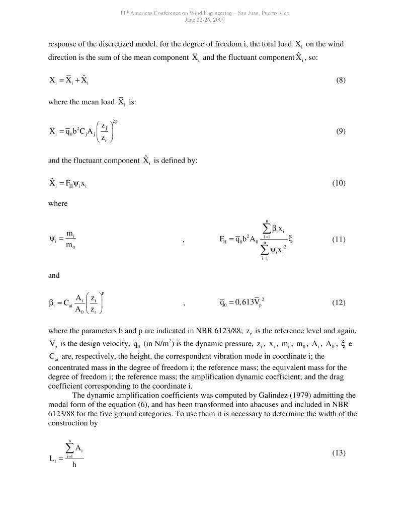
Photos of the structure are shown in Figure 2 and its geometry in Figure 3.
Figure 2: Photos of the structure.
This type of structure predominantly is submitted to bending effects. In these cases, the
item 15.7.3 of the NBR 6118/03, allows to use ci c0,5E I in the approached analyses considering
the physical not-linearity of the concrete, for structures with Gamma Z less than 1.3. The Gamma
Z coefficient measures the global efforts importance of the second order, being calculated for the
following expression:
ztot ,d
1,tot,d
1
M1
M
γ =∆
−
(15)
where:
1,tot,dM is the bending moment on the structure base,
tot ,dM∆ is the sum up of all products of the vertical forces developed in the structure by the
displacements of its respective points of application, gotten in the first order analysis.
It is important to mention the necessity of more detailed studies to validate the
application of the coefficient Gamma Z in reinforced concrete poles analysis. The coefficient
Gamma Z (γz), gotten by the efforts in linear discrete dynamic analysis is 1.05.
20
580
600
700
27
00
460
0
140
80
80
VAR
70
e = 15
e = 15
e = 13
Soil
Figure 3: Geometry - measures in centimeters.

The natural vibration frequencies and modes were numerically obtained via Finite
Element Method. The structure was modeled by beam elements of constant and variable cross
sections. We defined 51 finite elements for foundations and superstructure. We considered the
structure clamped at its base and the soil modeled by lateral distributed springs with stiffness
around 2668.93 kN/m3. We have also considered a lumped mass at the top and distributed mass
along the pole due to the ladder and cables. These masses also produce axial forces in the
structure.
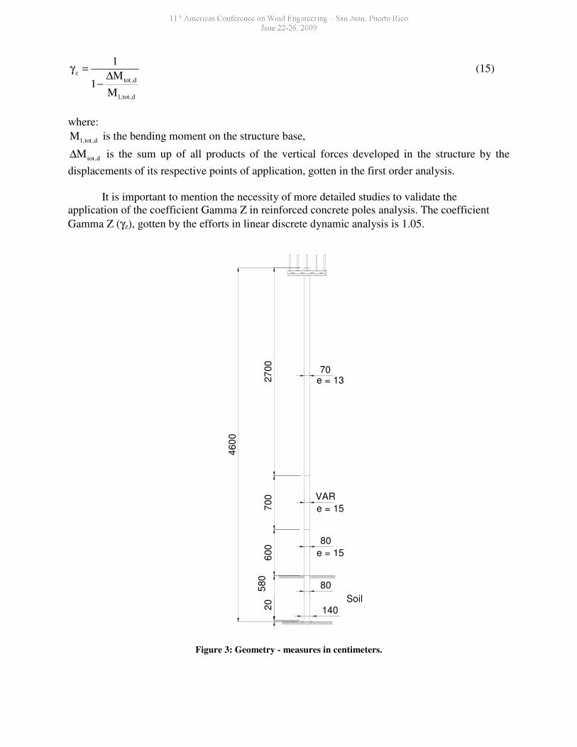
Figure 4 presents the finite element model and its discretization. The vibration mode and
the obtained frequencies are presented in Figure 5.
Figure 4: Finite Element Model.
(a) 3D Model
(b) Lateral view
(a) Discretization
Nat
ura
l m
od
es o
f v
ibra
tion
1st Mode 2
nd Mode 3
th Mode 4
th Mode 5
th Mode
Linear 0.2169 Hz 1.1958 Hz 3.3887 Hz 6.2485 Hz 10.1235 Hz
NLG e NLM 0.1413 Hz 0.9138 Hz 2.5481 Hz 5.0020 Hz 8.0972 Hz
(NLG represents a non-linearity of the geometry and NLM a non-linearity of the material)
Figure 5: Natural Modes of vibration
RESULTS
Parameters used in the analysis of the wind action are: topography factor S1 = 1.1; asperities
factor of the ground S2 corresponding to the category IV, class B, according to expression (2)
using the parameters p = 0.125, b = 0.85 e Fr = 0.98 (Table 2); statistic factor S3 = 1.1; basic
velocity of the wind V0 = 35 m/s and height over ground of 40 m.
In the dynamic response determination, using the simplified continuous model, the
following parameters were used: width of construction 0.723 m and height of 46 m for the
calculation of the frequency. The basic frequency was gotten making T1 = 0.02h (
Table 1), resulting f1 = 1.0870 Hz. The modal form obeyed expression (6) with γ equals to 2.7.
Known the design airspeed and the natural frequency of the structure, we computed the non
dimensional relation Vp/(f1L) of 0.013, which leads, with a critical ratio of damping ζ equal to
0.015, to a coefficient of dynamic amplification ξ of 1.131.
Calculating the structure frequency by using the Finite Elements Method, without
nonlinear considerations, a frequency for the fundamental mode is around 0.2169 Hz. The non
dimensional relationship Vp/(f1L) for linear discrete dynamic analysis becomes 0.075, which
leads to a dynamic amplification factor ξ around 1.702, considering the same critical damping. In
a discrete dynamic response calculation, with the inclusion of the geometric and material not-
linearity, additional modes 2 to 5, the dynamic amplification factors, given the frequencies
presented in Figure 5, are, respectively: 1.796; 1.492; 1.321; 1.321, for the same ratio of critical
damping.
For the critical damping ratio of 0.01, the simplified dynamic model has the modal form
of the Equation (6) and a correspondent exponent 1.7. The period of oscillation in the first mode
is computed as 1.5% of the structure height, which supplies the fundamental frequency of 0.69
Hz, leading to a dynamic amplification coefficient of 1.740. When the structure frequency is
gotten by a linear Finite Elements model, the dynamic amplification coefficient, for the wind
action calculation of the linear discrete dynamic model is ξ=2.553. If frequencies are calculated
using a nonlinear finite element model, presented in Figure 5 and the dynamic amplification

coefficients obtained are 2.703, 1.769, 1.470, 1.301 and 1.302, correspondent to each vibration
mode.
We have evaluated the differences due to the choice of damping ratios between a linear analysis
and a fully geometric and material nonlinear one. For a damping ratio equal to 0.015 the difference
between maximum bending moments obtained in a linear analysis and a nonlinear one is 18%.
0
200
400
600
800
1000
1200
1400
1600
0 10 20 30 40
Height (m)
Mo
me
nt
(kN
m)
Static ModelSimplified Dynamic ModelLinear Discret Dynamic ModelNon Linear Discret Dynamic Model - Mode 1Non Linear Discret Dynamic Model - Mode 1 and 2Non Linear Discret Dynamic Model - Mode 1 to 3Non Linear Discret Dynamic Model - Mode 1 to 4Non Linear Discret Dynamic Model - Mode 1 to 5
Figure 6: Wind action (ζ = 0.015)ζ = 0.015)ζ = 0.015)ζ = 0.015)
For a damping ratio of 0.01 the difference between the maximum bending moment for the linear
analysis and a nonlinear one reaches 41%.
0
200
400
600
800
1000
1200
1400
1600
0 10 20 30 40
Height(m)
Mo
me
nt
(kN
m)
Static ModelSimplified Dynamic ModelLinear Discret Dynamic ModelNon Linear Discret Dynamic Model - Mode 1Non Linear Discret Dynamic Model - Modes 1 and 2Non Linear Discret Dynamic Model - Mode 1 to 3Non Linear Discret Dynamic Model - Mode 1 to 4Non Linear Discret Dynamic Model - Mode 1 to 5
Figure 7: Wind action (ζ = 0.01)ζ = 0.01)ζ = 0.01)ζ = 0.01)
For any critical damping ratio the fluctuations of the first mode represent the most
significant contributions in the structure response.
ACKNOWLEDGEMENT
The authors express theirs gratefulness for the support given by CAPES and CNPq. Both are
research funding Brazilian federal agencies.

REFERENCES
[1] Associação Brasileira de Normas Técnicas (ABNT); NBR 6123 - Forças devidas ao vento em
edificações. Rio de Janeiro, dez. 1987.
[2] R. Brasil; M. Silva; A. Wahrhaftig. Non-Linear Dynamic Analysis Based on Experimental Data of RC
telecommunication Towers to Wind Loading. Twelfth International Conference On Wind Engineering
(12icwe). Cairns, Austrália, 2007.
[3] R. Brasil, M. Silva, D. Bower, N.J. Smit., RC large displacements: Optimization applied to
experimental results. Journal of Computers & Stuctures 84 (2006) 1164-1171, Ed Elsevier, 2006.
[4] A. Wahrhaftig. An experimental and numerical evaluation of the geometric stiffness effect on the
dynamic response of slender structures under wind excitation (in Portuguese), Doctorate Thesis,
University of São Paulo, São Paulo, Brasil, 2008.
[5] J. Blessmann. Ação do Vento em edifícios. 2 ed., rev. Ed. Universidade/UFRGS. Porto Alegre, 1989.
[6] E. Simiu, R. H. Scalan. Wind Effects on Structures – Fundamentals and Applications Design, John
Wiley & Sons. New Yok, 1996.
[7] Associação Brasileira de Normas Técnicas (ABNT); NBR 6118/04 - Projeto de Estruturas de
Concreto Armado. Rio de Janeiro, mar. 2003.