Inflatable structures for Mars Base 10 - SpaceArchitect.org · Inflatable Structures for Mars Base...
12
American Institute of Aeronautics and Astronautics 1 Inflatable Structures for Mars Base 10 Thomas Sinn 1 Advanced Space Concepts Laboratory / University of Strathclyde, Glasgow, G1 2TB, United Kingdom Ondrej Doule 2 Space Innovations / International Space University, Illkirch-Graffenstaden, 67400, France A permanent manned settlement on the Martian surface requires the use of advanced technology concepts in order to become technically and financially feasible. The former developed Mars Base 10 concept incorporates novel ideas, increasing the feasibility of a continous human base on Mars. The most advanced feature of the MB10 design is the concept of increasing the habitable space of the Mars base once landed with an inflatable torus like structure. This paper gives an overview on the MB10 design and has its primary focus on the deployment of the inflatable structure. The deployment simulations show the final inflated shape of the MB10 concept on Mars from an un-inflated initial shape on Earth. The deployment strategy, simulations and rigidization techniques are discussed to provide a conceptual solution for large inflatable components of the MB10 habitat. Further applications of secondary inflatable smart structures are presented as well. These secondary structures are self deploying at the Martian ambient pressure which results in low storage volume and mass. These structures are well-suited to carry on for astronauts on EVAs for example. Nomenclature EDL = Entry Descent Landing EVA = Extra Vehicular Activity EVOH = Ethylene Vinyl Alcohol FEM = Finite Element Method IMOD = Inflatable Module (Thales Study) ISRU = In Situ Resource Utilisation LEO = Low Earth Orbit LMO = Low Mars Orbit MB10 = Mars Base 10 NASA ARC = NASA Ames Research Center PA-NYLON = Polyamide PE = Polyethylene PVDC = Polyvinylidene Chloride PU = Polyurethane SAM = Self-inflating Adaptive Membrane SMP = Shape Memory Polymer TRL = Technology Readiness Level UV = Ultraviolet 1 M.Sc., Ph.D.-Candidate, Advanced Space Concepts Laboratory / University of Strathclyde, Department of Mechanical & Aerospace Engineering, 347 Cathedral Street, Glasgow G1 2TB, Glasgow, United Kingdom, [email protected] , and AIAA member since 2008. 2 M.Arch., M.Sc., Ph.D, Space Innovations / International Space University, Parc d’I nnovation, 1, rue JeanDominique Cassini, 67400 Illkirch-Graffenstaden, France 42nd International Conference on Environmental Systems 15 - 19 July 2012, San Diego, California AIAA 2012-3557 Copyright © 2012 by Thomas Sinn, Ondrej Doule. Published by the American Institute of Aeronautics and Astronautics, Inc., with permission.
Transcript of Inflatable structures for Mars Base 10 - SpaceArchitect.org · Inflatable Structures for Mars Base...

American Institute of Aeronautics and Astronautics
1
Inflatable Structures for Mars Base 10
Thomas Sinn
1
Advanced Space Concepts Laboratory / University of Strathclyde, Glasgow, G1 2TB, United Kingdom
Ondrej Doule2
Space Innovations / International Space University, Illkirch-Graffenstaden, 67400, France
A permanent manned settlement on the Martian surface requires the use of advanced
technology concepts in order to become technically and financially feasible. The former
developed Mars Base 10 concept incorporates novel ideas, increasing the feasibility of a
continous human base on Mars. The most advanced feature of the MB10 design is the
concept of increasing the habitable space of the Mars base once landed with an inflatable
torus like structure. This paper gives an overview on the MB10 design and has its primary
focus on the deployment of the inflatable structure. The deployment simulations show the
final inflated shape of the MB10 concept on Mars from an un-inflated initial shape on Earth.
The deployment strategy, simulations and rigidization techniques are discussed to provide a
conceptual solution for large inflatable components of the MB10 habitat. Further
applications of secondary inflatable smart structures are presented as well. These secondary
structures are self deploying at the Martian ambient pressure which results in low storage
volume and mass. These structures are well-suited to carry on for astronauts on EVAs for
example.
Nomenclature
EDL = Entry Descent Landing
EVA = Extra Vehicular Activity
EVOH = Ethylene Vinyl Alcohol
FEM = Finite Element Method
IMOD = Inflatable Module (Thales Study)
ISRU = In Situ Resource Utilisation
LEO = Low Earth Orbit
LMO = Low Mars Orbit
MB10 = Mars Base 10
NASA ARC = NASA Ames Research Center
PA-NYLON = Polyamide
PE = Polyethylene
PVDC = Polyvinylidene Chloride
PU = Polyurethane
SAM = Self-inflating Adaptive Membrane
SMP = Shape Memory Polymer
TRL = Technology Readiness Level
UV = Ultraviolet
1 M.Sc., Ph.D.-Candidate, Advanced Space Concepts Laboratory / University of Strathclyde, Department of
Mechanical & Aerospace Engineering, 347 Cathedral Street, Glasgow G1 2TB, Glasgow, United Kingdom,
[email protected] , and AIAA member since 2008. 2 M.Arch., M.Sc., Ph.D, Space Innovations / International Space University, Parc d’Innovation, 1, rue
JeanDominique Cassini, 67400 Illkirch-Graffenstaden, France
42nd International Conference on Environmental Systems15 - 19 July 2012, San Diego, California
AIAA 2012-3557
Copyright © 2012 by Thomas Sinn, Ondrej Doule. Published by the American Institute of Aeronautics and Astronautics, Inc., with permission.

American Institute of Aeronautics and Astronautics
2
I. Introduction
ESTRICTED by launch vehicle dimensions, future extraterrestrial outposts need to be designed and built
deployably to provide the habitable volume required for long term human space missions. One innovative
option to overcome these restrictions is the use of inflatable structures. Inflatable structures are an emerging class of
gossamer structures enabling very high volume to mass ratio spacecrafts. For the last decades, research institutes
across the globe were working on this promising structural concept to increase its TRL to become a major
alternative to conventional space structures. [1,2] New membrane materials have been discovered that can withstand
the space environment, advanced simulation tools were developed that capture the highly non-linear behavior of the
inflation process and rigidization techniques have been investigated making the structure non-reliant on the inflation
gas after deployment. [3,4] Inflatable structures have a number of benefits, including their simple deployment
mechanism, deployment reliability, and ease of manufacturing. All these attributes are of great importance to human
spaceflight in order to make them affordable with the budget constraints given to all space agencies nowadays. A
habitable structure holding an artificial atmosphere such as the Mars Base 10 (MB10) concept is extremely
dependent on structures like inflatables that enable rapid deployment of habitable volume. [5,6] A rapid deployment
enables the use of the entire habitation space immediately after landing on the Martian surface. Folded and stowed
inflatable structures are able to withstand the launch and landing loads easily with the non-existestence of any rigid
parts or joint elements. An inflating system has the capability of a completely autonomous deployment without the
need of any additional and probably dangerous EVA work of the astronauts.
II. Design of Mars Base 10
This paper focuses on the deployment simulation of large inflatable pressurized structures for Martian
greenhouses as part of the MB10 design. Further applications of other highly flexible smart inflatable structures are
introduced as well. These smart structures can adapt themselves to various environmental conditions increasing the
versatility of MB10 which can be seen in Figure 1.
Figure 1: 3D sketch of the MB10 deployed on Martian surface.
A. Mission Design of Mars Base 10
The main goal of the mission to Mars envisioned in the scenario is considering the MB10 base [7,8] as a main
pillar to provide a permanent habitat for a crew of 10 astronauts on the Martian surface. The main purpose of the
Mars Base 10 is to enable scientific research on the surface of Mars while withstanding the harsh environmental
conditions. The scientific objectives include search for extinct or extant Martian life (primarily astrobiology
research) and Mars climate surveillance which were given by Dr. McKay from NASA ARC as a part of a task for a
MB10 concept design in 2008.
R

American Institute of Aeronautics and Astronautics
3
The mission strategy considers a high number of important elements that
are currently not accessible or that are under development at the moment. A
heavy launch vehicle will be the major component to deliver the entire
structure to the Martian surface. The launcher has to be capable of launching a
mass of 136 tons to LEO and thus be able to deliver the 30 tons MB10
module payload to an orbit around Mars. Although the MB10 module
interplanetary transfer is unmanned and the module is intended to perform an
automatic Entry Descent Landing (EDL) sequence, it has to be supported by a
number of elements including an additional spacecraft transporting the crew
from LEO to LMO, a spacecraft for transport from LMO to the Mars surface
(Figure 2), heavy pressurized rovers for power generator placement, ISRU, crew transport and exploration.
Aditionally there is the need for a constellation of Mars stationary orbit and polar orbit satellites for remote sensing,
communication, navigation and weather forecasting which preferably should be launched first.
Figure 3: MB10 EDL sequence scheme (left A) and on-surface deployment scheme (right B)
The MB10 habitat and greenhouse, folded in one blunt body capsule, is the topic of this paper (Figure 3).
Particular focus is given to the inflatable structures which are the most critical part (Figure 4) of the proposed Mars
base. Radiation protection is achieved by water tanks on top of almost the entire structure. Thermal control to the
ground will be realized with trapped air layers in the bladder material on the ground; the trapped air will greatly
increase the insulation capabilities of the membrane itself. Their deployment stowage possibility needs to be
explored to confirm feasibility of the MB10 habitat concept.
Figure 2: MB10 module during
Martian atmospheric entry

American Institute of Aeronautics and Astronautics
4
Figure 4: MB10 section – functional
B. Inflatable Structure
The Inflatable structures are stowed in a blunt body (Figure 2) of the MB10 module during launch, interplanetary
journey to Mars and landing on the extraterrestrial body. The deployment of the inflatable structures is performed
after touchdown on the Martian surface. The inflation gets initiated after the successful deployment of the solar
panels that are structurally a part of the blunt body shell and behind which the inflatable structure is stored during
the interplanetary journey. The next step is the inflation process that utilizes atmospheric gas tanks on board of the
MB10 (Figure 10, appendix). The goal is to provide a presuure of 1 bar in the inflatable greenhouses as an optimum
for the benefits of the crew that will have the possibility to “live in” the greenhouses, to maintain and operate them
personally. Greenhouses may nevertheless operate also in lower pressure conditions as a backup solution. The
inflatable structure can be adjusted according to the structure deployment system. The inflatable structure should not
exceed the windows of the command center and it should have a mild, 1-5 degrees roof like slope on top to decrease
the risk of buildup of debris or dust from possible Martian sand storms.
C. Inflatable Simulations
The program used for the simulation of the inflatable system was LS-DYNA by Livermore Software Technology
Corporation (LSTC). LS-DYNA is a popular simulation tool for inflatable structures in the industry, mainly for
airbag deployment simulation. Another reason why LS-DYNA was selected for this kind of study was its
availability with an ANSYS/LS-DYNA academic license at the University of Strathclyde, Glasgow, UK. The LS-
DYNA software’s code is based on highly non-linear, transient dynamic finite element analysis using explicite time
integration3. LS-DYNA’s flexible finite element analysis packages were used e.g., on NASA JPL Mars Pathfinders
airbags landing simulations. Other areas where this software is used include automotive industry (crash simulations),
explosions (naval, underwater) and metal manufacturing (sheet metal stamping).
1. Simulation Setup
The used *AIRBAG_SIMPLE_AIRBAG_MODEL_ID is a LS-DYNA model which employs the control volume
method. The *AIRBAG_SIMPLE_AIRBAG_MODEL_ID method was developed to simulate the inflation of
airbags by assuming an equal pressure to the inside of a defined control volume, e.g. the whole airbag. The particle
method is more precise but requires more computational power. For the simulations a simplified rigid conical shape
3 http://www.lstc.com/products/ls-dyna
American Institute of Aeronautics and Astronautics
5
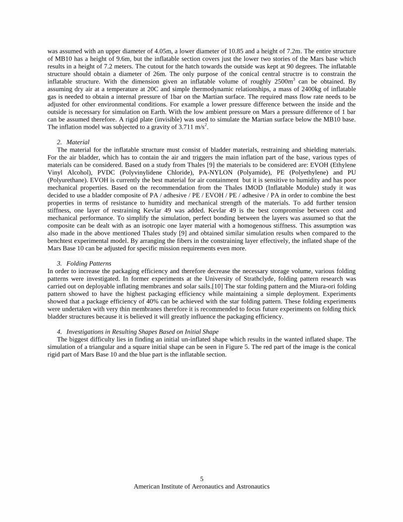
was assumed with an upper diameter of 4.05m, a lower diameter of 10.85 and a height of 7.2m. The entire structure
of MB10 has a height of 9.6m, but the inflatable section covers just the lower two stories of the Mars base which
results in a height of 7.2 meters. The cutout for the hatch towards the outside was kept at 90 degrees. The inflatable
structure should obtain a diameter of 26m. The only purpose of the conical central structre is to constrain the
inflatable structure. With the dimension given an inflatable volume of roughly 2500m3 can be obtained. By
assuming dry air at a temperature at 20C and simple thermodynamic relationships, a mass of 2400kg of inflatable
gas is needed to obtain a internal pressure of 1bar on the Martian surface. The required mass flow rate needs to be
adjusted for other environmental conditions. For example a lower pressure difference between the inside and the
outside is necessary for simulation on Earth. With the low ambient pressure on Mars a pressure difference of 1 bar
can be assumed therefore. A rigid plate (invisible) was used to simulate the Martian surface below the MB10 base.
The inflation model was subjected to a gravity of 3.711 m/s2.
2. Material
The material for the inflatable structure must consist of bladder materials, restraining and shielding materials.
For the air bladder, which has to contain the air and triggers the main inflation part of the base, various types of
materials can be considered. Based on a study from Thales [9] the materials to be considered are: EVOH (Ethylene
Vinyl Alcohol), PVDC (Polyvinylidene Chloride), PA-NYLON (Polyamide), PE (Polyethylene) and PU
(Polyurethane). EVOH is currently the best material for air containment but it is sensitive to humidity and has poor
mechanical properties. Based on the recommendation from the Thales IMOD (Inflatable Module) study it was
decided to use a bladder composite of PA / adhesive / PE / EVOH / PE / adhesive / PA in order to combine the best
properties in terms of resistance to humidity and mechanical strength of the materials. To add further tension
stiffness, one layer of restraining Kevlar 49 was added. Kevlar 49 is the best compromise between cost and
mechanical performance. To simplify the simulation, perfect bonding between the layers was assumed so that the
composite can be dealt with as an isotropic one layer material with a homogenous stiffness. This assumption was
also made in the above mentioned Thales study [9] and obtained similar simulation results when compared to the
benchtest experimental model. By arranging the fibers in the constraining layer effectively, the inflated shape of the
Mars Base 10 can be adjusted for specific mission requirements even more.
3. Folding Patterns
In order to increase the packaging efficiency and therefore decrease the necessary storage volume, various folding
patterns were investigated. In former experiments at the University of Strathclyde, folding pattern research was
carried out on deployable inflating membranes and solar sails.[10] The star folding pattern and the Miura-ori folding
pattern showed to have the highest packaging efficiency while maintaining a simple deployment. Experiments
showed that a package efficiency of 40% can be achieved with the star folding pattern. These folding experiments
were undertaken with very thin membranes therefore it is recommended to focus future experiments on folding thick
bladder structures because it is believed it will greatly influence the packaging efficiency.
4. Investigations in Resulting Shapes Based on Initial Shape
The biggest difficulty lies in finding an initial un-inflated shape which results in the wanted inflated shape. The
simulation of a triangular and a square initial shape can be seen in Figure 5. The red part of the image is the conical
rigid part of Mars Base 10 and the blue part is the inflatable section.

American Institute of Aeronautics and Astronautics
6
a) b)
c) d)
Figure 5: (a,c) initial shapes before folding; (b,d) final shapes after unfolding and inflation
The rectangular approach clearly requires a higher amount of membrane material then the triangular approach but
also offers more habitation volume.
5. Results
For the inflation simulation, a fully constructed inflated structure was modeled in the LS-DYNA pre-compressor
LS-PREPOST. Close attention was payed to create a structure similar to the outline of the MB10 design described in
the beginning of the paper. The modeled structure can be seen in Figure 6 where the red part is the rigid part of the
landing apparatus and the blue elements are the inflatable structure.
a) b)
Figure 6: (a) Isometric and (b) front view of FEM set up for inflation simulation
The prediction of the inflated shape before inflation is difficult if the shapes are getting more complex. Often the
modeled shape before folding looks different to the final inflated shape. Therefore the bending moment of each of
the FEM elements is not equal to zero.The folding of the structure was realized by using rigid moving walls that are
compressing the structure from four sides and the top until the structure is attached closely to the conical rigid part

American Institute of Aeronautics and Astronautics
7
(red). This storage of the inflatable structure is done in the same simulation as the deployment in order to ensure that
the shell elements of the inflating structure remember their initial shape without getting distorted.
Figure 7: Displacement resultant contour plot of deploying MB10 inflatable part with 0.2 seconds simulation
time steps
Figure 7 shows the deployment simulation of the Mars Base 10 with displacement resultant contour plots in 0.2
seconds steps. The fast deployment inflation time of four seconds was chosen to decrease the computational time
significantly. Longer LS-DYNA simulations were carried out to validate the shorther inflation time. A 30 second
inflation time simulation showed similar results to the shorter one. It was therefore decided to continue the study
with the shorther, less computational expensive simulations. Figure 11 in the appendix shows the mass inflow, the
total mass, the internal pressure and the internal volume of the inflation process. It can be seen, especially in the
volume plot, that the structure is getting compressed towards the rigid cone in the first second. In the first second the
deployable structures is getting folded and stored in LS-DYNA. After one second, the deployment starts with a
triangular mass inflow. Earlier experiments on inflatable tubes for tensegrity structures [11] showed that the
triangular mass inflow can be assumed from a gas generator. Furthermore, the pressure plot in Figure 11 shows that
after 4 seconds of inflation time (5 seconds total elapsed time), the internal pressure reaches 100000Pa which is the
required one atmosphere with the inflation volume of 2500m3.
6. Overview of Available Rigidization Technologies
In order to make the structure rigid and resistant to micrometeoroid and space-debris impact [12], the structure
needs to be rigidized from the flexible inflated state to a stiff rigid state. The rigidization also serves the purpose of
obtaining a structure that is independent on the inflation gas after inflation. The rigidization technologies range from
thermally cured thermosets to expandable aluminum film composites. The following overview gives a quick
summary on available rigidization techniques today. It is not meant to be a detailed scientific explanation of each of
the available technologies. For more detailed explanation on the technologies please refer to the references.
One option is the use of thermally cured thermoset composites that consist of a fibrous substructure impregnated
with a thermoset polymer resin. By introducing heat by for example solar illumination or resistive heating, the resin
will cure and rigidize the structure [13]. With glass transition temperature rigidization, the stored structure is heated
by the surrounding electronics and therefore stays flexible. As soon as the structure gets subjected to the cold space
environment the structure becomes rigid [14]. The composites are also known as second order transition change or
SMP composites. Another option are composites that cure in ultraviolet (UV) light [15,16]. The inflated structure is
impregnated with a resin that will cure at certain wavelengths. The two ways of rigidizing the structure are either
through the UV energy of the sun or the energy transmitted by UV lights embedded in the structure. The use of

American Institute of Aeronautics and Astronautics
8
plasticizer or solvent boil-off is another possibility to rigidize inflatable structures. The principle behind this
technique is that a softening component in the resin evaporates once subjected to the space environment and thereby
rigidizes the composite. Foam rigidization fills the cavities of the inflating structure with structural foam that
reinforces the structure once deployed. The oldest technology is the aluminum and film laminate rigidization
technology which was used in NASA’s ECHO II program in the 1960s. The thin laminates used for this approach
are made from ductile aluminum and polymer film. The principle behind this technique is to stretch the aluminum
beyond the aluminum`s hardening stress. After stretching, the pressure is released and the aluminum is in a
compressive stage while the polymer is still in its elastic range, the result is a rigid structure.
One of the biggest problems with the ridization is that in a real life application the rigidization will most likely
be uneven which is almost impossible to predict or simulate. Another factor that needs to be considered is the
toxicity to the environment of the various rigidization techniques. The toxic rigidizing structures need to be arranged
in a way that there is no danger for the crew. One option would be the introduction of various different layers of
material, like a protection cover layer.
D. Inflatable Smart Structures
The Mars Base 10 offers countless additional application areas for inflatable structures. Current research at the
Advanced Space Concepts Laboratory is focused on smart inflatable structures which can adapt themselves to
various mission requirements and stages. The idea
behind the inflatable structure is to develop a structure
which is lightweight, easily deployable and adaptable to
its environment. Such a smart space structure which
uses the principle of nature’s heliotropism is outlined
here. Heliotropism is the growth or movement of an
organism towards the direction of the sunlight. By
changing the turgor pressure between adjacent cells in
the plant’s stem, called motor cells, the stem of the plant
flexes. Due to the simplicity of the principle, the
movement due to pressure change seems perfect for the
application on deployable space structures. The design
of the Self-inflating Adaptive Membrane (SAM) [10]
consists of an array of cells which are inflated by
employing residual air inflation. An array of 38
spherical elements can be seen in Figure 8.
Residual air inflation uses the expansion of trapped air inside the structure when subjected to vacuum conditions
to inflate the structure. A high packing efficiency and deployment reliability can be achieved by using this passive
deployment technique coupled with a multiple unit membrane design. Figure 9 shows two inflating benchtest
spheres in the vacuum chamber. By assuming Mars’ atmospheric pressure of 4-5mbar and low gravity, the
deployment using residual air inflation will be sufficient. The available inflatable volume can be further increased by
either adding a coating that undergoes a phase-change in vacuum conditions [17] or a powder that sublimes into gas
to provide additional vapor pressure to the inflating structure [18]. In order to adapt heliotropism to these space
membranes, micro pumps were added between two adjacent cells to create a pressure difference between them
resulting in a volume variation of the two cells.
These Self-inflating Adaptive Membranes (SAM)
have various application areas in and around Mars Base
10; they can be used as transmission antennas, solar
concentrators adjusting the focal point based on the
season to increase their efficiency or as sun shields also
in form of small shelters to protect parts of Mars Base
10 or any deployed scientific, mining, or transportation
hardware against radiation and Martian sand storms.
They can be used for portable EVA shelters for crew as
well as hardware. Further application may include also
components of deployable exploration flyers and backup
hardware. The big advantage of these structures is that
they can be deployed out of a small container wherever,
Figure 8: Deployment simulation on array of 19
spherical units
Figure 9 Circular prototypes inflating under vaccum
conditions

American Institute of Aeronautics and Astronautics
9
whenever they are needed. It is therefore not necessary to transport the deployed structure first into earth orbit and
then to Mars. The transport of SAM in the storage box also decreases the risks of damaging the structure on the
journey to Mars from micro meteoroids or high radiation environments for example in the van-Allen belts.
III. Conclusion
This paper shows the design of a large inflatable MB10 greenhouse based on an optimal solution with a vision to
broaden the application of inflatable structures on the Mars base MB10 with regards to different environmental
conditions. The presented MB10 design has a conical rigid body that lands on the Martian surface and then deploys
an inflating torus-like structure to increase the habitation space. An inflation simulation was carried out to provide
an increase of habitation space from 291m3 by a magnitude to 2500m
3 with a pressure environment of one
atmosphere due to the inflating structure. Such an increase of volume can only be achieved by inflatable structures
nowadays. As a bladder material a composite of EVOH (Ethylene Vinyl Alcohol, PE (Polyethylene) and PU
(Polyurethane) was used. The simulation presented showed a FEM model of a deployed Mars Base 10 which got
then stored by compressing it with rigid moving walls followed by the inflation deployment. For this simulation a
very short inflation time of just 4 seconds was used to decrease the computational time and memory required for the
simulation. Additionally, the paper shows the difficulty of obtaining the initial shape of the inflating part of the Mars
Base. The two initial shapes presented are the triangular and rectangular approach which were simulated with the
simple airbag method of LS-DYNA. Further research needs to be undertaken with longer inflation times on a more
powerful computational system. Further applications of inflatable structures have been outlined as well, the research
showed that a new kind of smart membrane called SAM can be used for various application in and around Mars
Base 10, for example as concentrators, reflectors or protection devices.

American Institute of Aeronautics and Astronautics
10
Appendix
In the following the detailed structural layout of MB10 (Figure 10) and the inflation curves of the MB10
simulation in Figure 7 can be seen (Figure 11). The Figures show the mass inflow, the total mass of the MB10, the
internal pressure and the internal volume of the inflating structure.
Figure 10: Structural scheme of MB10 section

American Institute of Aeronautics and Astronautics
11
a) b)
c) d)
Figure 11: (a) Mass inflow of inflation gas, (b) total mass of inflating system, (c) internal pressure and (d)
internal volume of deploying inflatable structure of Mars Base 10
Acknowledgments
The authors would like to thank the Advanced Space Concepts Laboratory of the University of Strathclyde and
the International Space University for their continuous support in this research. Furthermore the authors would like
to thank the technician Tom McCanny of Strathclyde’s department of physics workshop to help in finding new
workspace for the bench tests of the inflatable structures outlined in this paper after a fire in the Mechanical
Engineering building of the University of Strathclyde.
References 1Freeland, R., Bilyeu, G., Veal, G., and Mikulas, M. "Inflatable deployable space structures technology summary," 49th
International Astronautical Congress. Melbourne, Australia, 1998.
2Bernasconi, M. C. "Flexible-wall expandable structures for space applications: forty years of trying" 1st European
Workshop on Inflatable Space Structures, 21-22 May. Noordwijk, The Netherlands, 2002.
3Bernasconi, M. C. "Chemically rigidized expandable structures (CRES): rigidization and materials," 2nd European
Workshop on Inflatable Space Structures, 21-23 June. Tivoli, Italy, 2004.
4Defoort, B. "Polymerization of composite materials in free space environment," 4th European Workshop on Inflatable
Structures, 16-18 June. Noordwijk, The Netherlands, 2008.
5 Kennedy, Kriss, “Lessons from TransHab: An Architect’s Experience” AIAA Space Architecture Symposium, 10-11
October 2002, Houston, Texas, AIAA 2002-6105
6 Petrov, G., Park, K. S. , Adams, c., "Optimization of Inflatable Spacecraft Interior Volume Using Constraints Driven
Design" AIAA 2010-6070, Proceedings of the 40th International Conference on Environmental Systems (ICES)

American Institute of Aeronautics and Astronautics
12
7Braun, R. D.; Manning, R. M., 2006. Mars Exploration Entry, Descent and Landing Challenges. Journal of Spacecraft and
Rockets, 44 (2), 310-323.
8Doule, O., 2009, Mars Base 10 - A Permanent Settlement on Mars for 10 Astronauts (SAE 2009-01-2385). 39th
International Conference on Environmental Systems (ICES), Savannah, Georgia, USA, 12-16 July 2009. Warrendale,
Pennsylvania, USA.
9 Nebiolo M., Palmieri, P., Gomiero, F., Pirolli M., Langlois, S.”Inflatable Technology for Manned Space Applications: the
IMOD Experience“, 5th European Workshop on Inflatable Space Structures, ESA/ESTEC, Noordwijk, The Netherlands, 10-12
May, 2011
10Sinn, T., Vasile, M., Gunnar, T. “Design and Development of Deployable Self-inflating Adaptive Membrane” AIAA-2012-
1517, 13th AIAA Gossamer Systems Forum as part of 53rd Structures, Structural Dynamics, and Materials and Co-located
Conferences, Honolulu, Hawaii, 23 - 26 April, 2012
11Sinn, T., Vasile, M. “Deployment Simulation of Very Large Inflatable Tensegrity Reflectors”, IAC-11.C2.2.10, 62nd
International Astronautical Congress (IAC) 2011, 3 – 7 October, Cape Town, South Africa, 2011
12Neal, M. "Meteoroid damage to filamentary structures (Micrometeoroid impact fracture rates in wire, flat tapes, and thin-
walled hollow tubes)," 1967. 30 P, 1967.
13Cadogan, D., and Scarborough, S. "Rigidizable materials for use in gossamer space inflatable structures," American
Institute of Aeronautics and Astronautics (AIAA 01-1417), 2001.
14Lichodziejewski, D., and Cassapakis, C. "Inflatable power antenna technology," 37th AIAA Aerospace Sciences Meeting
and Exhibit, January 11-14. Reno, Nevada, USA, 1999.
15Simburger, E. J., Lin, J. K., Scarborough, S. E., and Curtis, H. B. "Development, design, and testing of powersphere
multifunctional ultraviolet-rigidizable inflatable structures," Journal of spacecraft and rockets Vol. 42, No. 6, 2005, pp. 1091-
1100.
16Straubel, M. "On-ground Rigidised, Inflatable CFRP Booms for Various Deployable Space Structures," 5th European
Workshop on Inflatable Space Structures, 10-12 May. Noordwijk, The Netherlands, 2011.
17Cowan, T., Darling, A., Kruse, M., Llauro, A., Heitel, J., Kellam, C., Ohlson, M., Cheek, W., Lewis, M., VanPelt III, J.,
Buckley, D., Crosby, J., Sarisky, M., Argibay, N., Cabera, C., and Nipper, C. "Inflate-A-Brake - A Gossamer Structures
Technology Demostrator for De-orbiting Pico-Satellites," FUNSAT Design Competition - Gossamer Gators / University of
Florida, 2004.
18Simburger, E. J., Matsumoto, J., Lin, J., Knoll, C., Rawal, S., Perry, A., Barnett, D., Peterson, T., Kerslake, T., and Curtis,
H. "Development of a multifunctional inflatable structure for the powersphere concept," American Institute of Aeronautics and
Astronautics (AIAA 02-1707), 2002.