![INFCIRC 540c II HB INFCIRC 254 1 HB INFCIRC 254 2 ... - Europa · Dual-use equipment and materials listed in the NSG guidelines Part 2 [5]. References to the NSG exist in several](https://static.fdocuments.us/doc/165x107/60719199a00de01672150115/infcirc-540c-ii-hb-infcirc-254-1-hb-infcirc-254-2-europa-dual-use-equipment.jpg)
INFCIRC/254/Rev.13/Part 1 - Communication received from the … · 2018-09-11 · International...
121
Information Circular INFCIRC/254/Rev.13/Part 1 a Date: 8 November 2016 General Distribution Original: English Communication received from the Permanent Mission of the Republic of Korea to the International Atomic Energy Agency regarding Certain Member States’ Guidelines for the Export of Nuclear Material, Equipment and Technology 1. The Secretariat has received a note verbale from the Permanent Mission of the Republic of Korea, dated 24 October 2016, in which it requests that the Agency circulate to all Member States, a letter of 21 October 2016 from the Chairperson of the Nuclear Suppliers Group, Ambassador Young- wan Song, to the Director General, on behalf of the Governments of Argentina, Australia, Austria, Belarus, Belgium, Brazil, Bulgaria, Canada, China, Croatia, Cyprus, Czech Republic, Denmark, Estonia, Finland, France, Germany, Greece, Hungary, Iceland, Ireland, Italy, Japan, Kazakhstan, Republic of Korea, Latvia, Lithuania, Luxembourg, Malta, Mexico, Netherlands, New Zealand, Norway, Poland, Portugal, Romania, Russian Federation, Serbia, Slovakia, Slovenia, South Africa, Spain, Sweden, Switzerland, Turkey, Ukraine, the United Kingdom of Great Britain and Northern Ireland and the United States of America b , providing further information on those Governments' Guidelines for Nuclear Transfers. 2. In light of the wish expressed in the above-mentioned note verbale, the text of the note verbale, as well as the letter and attachments thereto, are hereby reproduced for the information of all Member States. __________________________________________________________________________________ a INFCIRC/254/Part 2, as amended, contains Guidelines for transfers of nuclear-related dual-use equipment, materials, software and related technology. b The European Commission and the Chair of the Zangger Committee participate as observers.
Transcript of INFCIRC/254/Rev.13/Part 1 - Communication received from the … · 2018-09-11 · International...
Information Circular
INFCIRC/254/Rev.13/Part 1a
Date: 8 November 2016
General DistributionOriginal: English
Communication received from the PermanentMission of the Republic of Korea to the
International Atomic Energy Agency regarding Certain Member States’ Guidelines for the Export of Nuclear Material, Equipment and
Technology
1. The Secretariat has received a note verbale from the Permanent Mission of the Republic of Korea, dated 24 October 2016, in which it requests that the Agency circulate to all Member States, a letter of 21 October 2016 from the Chairperson of the Nuclear Suppliers Group, Ambassador Young-wan Song, to the Director General, on behalf of the Governments of Argentina, Australia, Austria, Belarus, Belgium, Brazil, Bulgaria, Canada, China, Croatia, Cyprus, Czech Republic, Denmark, Estonia, Finland, France, Germany, Greece, Hungary, Iceland, Ireland, Italy, Japan, Kazakhstan, Republic of Korea, Latvia, Lithuania, Luxembourg, Malta, Mexico, Netherlands, New Zealand, Norway, Poland, Portugal, Romania, Russian Federation, Serbia, Slovakia, Slovenia, South Africa, Spain, Sweden, Switzerland, Turkey, Ukraine, the United Kingdom of Great Britain and Northern Ireland and the United States of Americab, providing further information on those Governments' Guidelines for Nuclear Transfers.
2. In light of the wish expressed in the above-mentioned note verbale, the text of the note verbale, as well as the letter and attachments thereto, are hereby reproduced for the information of all Member States.
__________________________________________________________________________________ a INFCIRC/254/Part 2, as amended, contains Guidelines for transfers of nuclear-related dual-use equipment, materials, software and related technology.
b The European Commission and the Chair of the Zangger Committee participate as observers.
INFCIRC/254/Rev.13/Part 1 Attachment


NSG Part 1 Guidelines – INFCIRC/254/Rev.13/Part 1
- 1 -
GUIDELINES FOR NUCLEAR TRANSFERS
1. The following fundamental principles for safeguards and export controls should apply to
nuclear transfers for peaceful purposes to any non-nuclear-weapon State and, in the case
of controls on retransfer, to transfers to any State. In this connection, suppliers have
defined an export trigger list.
Prohibition on nuclear explosives
2. Suppliers should authorise transfer of items or related technology identified in the trigger
list only upon formal governmental assurances from recipients explicitly excluding uses
which would result in any nuclear explosive device.
Physical protection
3. (a) All nuclear materials and facilities identified by the agreed trigger list should be
placed under effective physical protection levels to prevent unauthorised use and
handling, consistent with the relevant International Atomic Energy Agency (IAEA)
recommendations, in particular those set out in Information Circular (INFCIRC)/225.
(b) The implementation of measures of physical protection in the recipient country is the
responsibility of the Government of that country. However, in order to implement the
terms agreed upon amongst suppliers, the levels of physical protection on which these
measures have to be based should be the subject of an agreement between supplier and
recipient.
(c) In each case, special arrangements should be made for a clear definition of
responsibilities for the transport of trigger list items.
Safeguards
4. (a) Suppliers should transfer trigger list items or related technology to a non-nuclear
weapon State only when the receiving State has brought into force an agreement with
the IAEA requiring the application of safeguards on all source and special fissionable
material in its current and future peaceful activities. Suppliers should authorise such
transfers only upon formal governmental assurances from the recipient that:
− if the above-mentioned agreement should be terminated the recipient will bring
into force an agreement with the IAEA based on existing IAEA model safeguards
agreements requiring the application of safeguards on all trigger list items or
related technology transferred by the supplier or processed, or produced or used in
connection with such transfers; and
− if the IAEA decides that the application of IAEA safeguards is no longer possible,
the supplier and recipient should elaborate appropriate verification measures. If
the recipient does not accept these measures, it should allow at the request of the
supplier the restitution of transferred and derived trigger list items.
NSG Part 1 Guidelines – INFCIRC/254/Rev.13/Part 1
- 2 -
(b) Transfers covered by paragraph 4(a) to a non-nuclear-weapon State without such a
safeguards agreement should be authorised only in exceptional cases when they are
deemed essential for the safe operation of existing facilities and if safeguards are
applied to those facilities. Suppliers should inform and, if appropriate, consult in the
event that they intend to authorise or to deny such transfers.
(c) The policy referred to in paragraph 4(a) and 4(b) does not apply to agreements or
contracts drawn up on or prior to April 3, 1992. In case of countries that have adhered
or will adhere to INFCIRC/254/Rev. 1/Part 1 later than April 3, 1992, the policy only
applies to agreements (to be) drawn up after their date of adherence.
(d) Under agreements to which the policy referred to in paragraph 4(a) does not apply (see
paragraphs 4(b) and (c)) suppliers should transfer trigger list items or related
technology only when covered by IAEA safeguards with duration and coverage
provisions in conformity with IAEA document GOV/1621. However, suppliers
undertake to strive for the earliest possible implementation of the policy referred to in
paragraph 4(a) under such agreements.
(e) Suppliers reserve the right to apply additional conditions of supply as a matter of
national policy.
5. Suppliers will jointly reconsider their common safeguards requirements, whenever
appropriate.
Special controls on sensitive exports
6. Suppliers should exercise a policy of restraint in the transfer of sensitive facilities,
equipment, technology and material usable for nuclear weapons or other nuclear explosive
devices, especially in cases when a State has on its territory entities that are the object of
active Nuclear Suppliers Group (NSG) Guidelines Part 2 denial notifications from more
than one NSG Participating Government.
(a) In the context of this policy, suppliers should not authorise the transfer of enrichment
and reprocessing facilities, and equipment and technology therefore if the recipient
does not meet, at least, all of the following criteria:
(i) Is a Party to the Treaty on the Non-Proliferation of Nuclear Weapons and is in
full compliance with its obligations under the Treaty;
(ii) Has not been identified in a report by the IAEA Secretariat which is under
consideration by the IAEA Board of Governors, as being in breach of its
obligations to comply with its safeguards agreement, nor continues to be the
subject of Board of Governors decisions calling upon it to take additional steps
to comply with its safeguards obligations or to build confidence in the peaceful
nature of its nuclear programme, nor has been reported by the IAEA Secretariat
as a state where the IAEA is currently unable to implement its safeguards
agreement. This criterion would not apply in cases where the IAEA Board of
Governors or the United Nations Security Council subsequently decides that
adequate assurances exist as to the peaceful purposes of the recipient's nuclear
programme and its compliance with its safeguards obligations. For the

NSG Part 1 Guidelines – INFCIRC/254/Rev.13/Part 1
- 3 -
purposes of this paragraph, “breach” refers only to serious breaches of
proliferation concern;
(iii) Is adhering to the NSG Guidelines and has reported to the Security Council of
the United Nations that it is implementing effective export controls as
identified by United Nations Security Council Resolution (UNSCR) 1540;
(iv) Has concluded an inter-governmental agreement with the supplier including
assurances regarding non-explosive use, effective safeguards in perpetuity, and
retransfer;
(v) Has made a commitment to the supplier to apply mutually agreed standards of
physical protection based on current international guidelines; and
(vi) Has committed to IAEA safety standards and adheres to accepted international
safety conventions.
(b) In considering whether to authorise such transfers, suppliers, while taking into account
paragraphs 4(e), 6(a), and 10, should consult with potential recipients to ensure that
enrichment and reprocessing facilities, equipment and technology are intended for
peaceful purposes only; also taking into account at their national discretion, any
relevant factors as may be applicable.
(c) Suppliers will make special efforts in support of effective implementation of IAEA
safeguards for enrichment or reprocessing facilities, equipment or technology and
should, consistent with paragraphs 4 and 14 of the Guidelines, ensure their peaceful
nature. In this regard suppliers should authorise transfers, pursuant to this paragraph,
only when the recipient has brought into force a Comprehensive Safeguards
Agreement, and an Additional Protocol based on the Model Additional Protocol or,
pending this, is implementing appropriate safeguards agreements in cooperation with
the IAEA, including a regional accounting and control arrangement for nuclear
materials, as approved by the IAEA Board of Governors.
(d) In accordance with paragraph 17(b) of the Guidelines, prior to beginning transfers of
enrichment or reprocessing facilities, equipment, or technology, suppliers should
consult with Participating Governments regarding the non-proliferation-related terms
and conditions applicable to the transfer.
(e) If enrichment or reprocessing facilities, equipment, or technology are to be transferred,
suppliers should encourage recipients to accept, as an alternative to national plants,
supplier involvement and/or other appropriate multinational participation in resulting
facilities. Suppliers should also promote international (including IAEA) activities
concerned with multinational regional fuel cycle centres.
Special arrangements for export of enrichment facilities, equipment and technology
7. All States that meet the criteria in paragraph 6 above are eligible for transfers of
enrichment facilities, equipment and technology. Suppliers recognise that the application
of the Special Arrangements below must be consistent with principles of the Treaty on the
Non-Proliferation of Nuclear Weapons (NPT), in particular Article IV. Any application by
NSG Part 1 Guidelines – INFCIRC/254/Rev.13/Part 1
- 4 -
the suppliers of the following Special Arrangements may not abrogate the rights of States
meeting the criteria in paragraph 6.
(a) For a transfer of an enrichment facility, or equipment or technology therefor, suppliers
should seek a legally-binding undertaking from the recipient state that neither the
transferred facility, nor any facility incorporating such equipment or based on such
technology, will be modified or operated for the production of greater than 20%
enriched uranium. Suppliers should seek to design and construct such an enrichment
facility or equipment therefor so as to preclude, to the greatest extent practicable, the
possibility of production of greater than 20% enriched uranium.
(b) For a transfer of an enrichment facility or equipment based on a particular enrichment
technology which has been demonstrated to produce enriched uranium on a significant
scale as of 31 December 2008, suppliers should:
(1) Avoid, as far as practicable, the transfer of enabling design and manufacturing
technology associated with such items; and
(2) Seek from recipients an appropriate agreement to accept sensitive enrichment
equipment, and enabling technologies, or an operable enrichment facility under
conditions that do not permit or enable replication of the facilities.
Information required for regulatory purposes or to ensure safe installation and
operation of a facility should be shared to the extent necessary without divulging
enabling technology.
(c) Cooperative enrichment enterprises based on a particular enrichment technology
which has not been demonstrated to produce enriched uranium on a significant scale as
of 31 December 2008, may be developed by participants individually or jointly; and
any transfer of the resulting facilities and equipment will become subject to paragraph
7(b) no later than prior to the deployment of a prototype. For the purposes of
paragraph 7(c) of the Guidelines, a prototype is a system or facility which is operated
to generate technical information to confirm the technical potential or viability of the
separation process for large-scale separation of uranium isotopes.
Suppliers may propose alternative arrangements relating to control of transfers of new
enrichment technology to facilitate cooperation on enrichment technology. Such
arrangements should be equivalent to those in paragraph 7(b), and the NSG should be
consulted on these arrangements. Participating Governments will review the
arrangements for export of enrichment facilities, equipment and technology every five
years beginning in 2013 for the purpose of addressing changes in enrichment
technology and commercial practices.
(d) Suppliers recognise that when implementing the arrangements envisaged by paragraph
7 in relation to existing and new cooperative enrichment enterprises, enabling
technology may be held by, shared among, and transferred between partners of such
enterprises, if partners agree to do so on the basis of their established decision making
processes. Suppliers recognise that uranium enrichment may involve supply chains for
the production and transfer of equipment for enrichment facilities and such transfers
can be made, subject to the relevant provisions of these Guidelines.
NSG Part 1 Guidelines – INFCIRC/254/Rev.13/Part 1
- 5 -
(e) Suppliers should make special efforts to ensure effective implementation of IAEA
safeguards at supplied enrichment facilities, consistent with paragraphs 14 and 15 of
the Guidelines. For a transfer of an enrichment facility, the supplier and recipient state
should work together to ensure that the design and construction of the transferred
facility is implemented in such a way so as to facilitate IAEA safeguards. The supplier
and recipient state should consult with the IAEA about such design and construction
features at the earliest possible time during the facility design phase, and in any event
before construction of the enrichment facility is started. The supplier and recipient
state should also work together to assist the recipient state in developing effective
nuclear material and facilities protection measures, consistent with paragraphs 13 and
15 of the Guidelines.
(f) Suppliers should satisfy themselves that recipients have security arrangements in place
that are equivalent or superior to their own to protect the facilities and technology
from use or transfer inconsistent with the national laws of the receiving state.
Definitions Section:
For the purpose of implementing paragraph 7 of the Guidelines “Cooperative Enrichment
Enterprise” means a multi-country or multi-company (where at least two of the companies
are incorporated in different countries) joint development or production effort. It could be
a consortium of states or companies or a multinational corporation.
Controls on supplied or derived material usable for nuclear weapons or other nuclear
explosive devices
8. Suppliers should, in order to advance the objectives of these guidelines and to provide
opportunities further to reduce the risks of proliferation, include, whenever appropriate
and practicable, in agreements on supply of nuclear materials or of facilities which
produce material usable for nuclear weapons or other nuclear explosive devices,
provisions calling for mutual agreement between the supplier and the recipient on
arrangements for reprocessing, storage, alteration, use, transfer or retransfer of any
material usable for nuclear weapons or other nuclear explosive devices involved.
Controls on retransfer
9. (a) Suppliers should transfer trigger list items or related technology only upon the
recipient’s assurance that in the case of:
(1) retransfer of such items or related technology,
or
(2) transfer of trigger list items derived from facilities originally transferred by the
supplier, or with the help of equipment or technology originally transferred by the
supplier;
the recipient of the retransfer or transfer will have provided the same assurances as
those required by the supplier for the original transfer.

NSG Part 1 Guidelines – INFCIRC/254/Rev.13/Part 1
- 6 -
(b) In addition the supplier’s consent should be required for:
(1) any retransfer of trigger list items or related technology and any transfer referred
to under paragraph 9(a) (2) from any State which does not require full scope
safeguards, in accordance with paragraph 4(a) of these Guidelines, as a condition
of supply;
(2) any retransfer of enrichment, reprocessing or heavy water production facilities,
equipment or related technology, and for any transfer of facilities or equipment of
the same type derived from items originally transferred by the supplier;
(3) any retransfer of heavy water or material usable for nuclear weapons or other
nuclear explosive devices.
(c) To ensure the consent right as defined under paragraph 9(b), government to
government assurances will be required for any relevant original transfer.
(d) Suppliers should consider restraint in the transfer of items and related technology
identified in the trigger list if there is a risk of retransfers contrary to the assurances
given under paragraph 9(a) and (c) as a result of a failure by the recipient to develop
and maintain appropriate, effective national export and transshipment controls, as
identified by UNSCR1540.
Non-proliferation Principle
10. Notwithstanding other provisions of these Guidelines, suppliers should authorise transfer
of items or related technology identified in the trigger list only when they are satisfied that
the transfers would not contribute to the proliferation of nuclear weapons or other nuclear
explosive devices or be diverted to acts of nuclear terrorism.
Implementation
11. Suppliers should have in place legal measures to ensure the effective implementation of
the Guidelines, including export licensing regulations, enforcement measures, and
penalties for violations.
SUPPORTING ACTIVITIES
Support for access to nuclear material for peaceful uses
12. Suppliers should, in accordance with the objective of these guidelines, facilitate access to
nuclear material for the peaceful uses of nuclear energy, and encourage, within the scope
of Article IV of the NPT, recipients to take the fullest possible advantage of the
international commercial market and other available international mechanisms for nuclear
fuel services while not undermining the global fuel market.
NSG Part 1 Guidelines – INFCIRC/254/Rev.13/Part 1
- 7 -
Physical security
13. Suppliers should promote international co-operation in the areas of physical security
through the exchange of physical security information, protection of nuclear materials in
transit, and recovery of stolen nuclear materials and equipment. Suppliers should promote
broadest adherence to the respective international instruments, inter alia, to the
Convention on the Physical Protection of Nuclear Material, as well as implementation of
INFCIRC/225, as amended from time to time. Suppliers recognise the importance of these
activities and other relevant IAEA activities in preventing the proliferation of nuclear
weapons and countering the threat of nuclear terrorism.
Support for effective IAEA safeguards
14. Suppliers should make special efforts in support of effective implementation of IAEA
safeguards. Suppliers should also support the IAEA's efforts to assist Member States in the
improvement of their national systems of accounting and control of nuclear material and
to increase the technical effectiveness of safeguards.
Similarly, they should make every effort to support the IAEA in increasing further the
adequacy of safeguards in the light of technical developments and the rapidly growing
number of nuclear facilities, and to support appropriate initiatives aimed at improving the
effectiveness of IAEA safeguards.
Trigger list plant design features
15. Suppliers should encourage the designers and makers of trigger list facilities to construct
them in such a way as to facilitate the application of safeguards and to enhance physical
protection, taking also into consideration the risk of terrorist attacks. Suppliers should
promote protection of information on the design of trigger list installations, and stress to
recipients the necessity of doing so. Suppliers also recognise the importance of including
safety and non-proliferation features in design and construction of trigger list facilities.
Export Controls
16. Suppliers should, where appropriate, stress to recipients the need to subject transferred
trigger list items and related technology and trigger list items derived from facilities
originally transferred by the supplier or with the help of equipment or technology
originally transferred by the supplier to export controls as outlined in UNSCR1540.
Suppliers are encouraged to offer assistance to recipients to fulfil their respective
obligations under UNSCR1540 where appropriate and feasible.
Consultations
17. (a) Suppliers should maintain contact and consult through regular channels on matters
connected with the implementation of these Guidelines.
(b) Suppliers should consult, as each deems appropriate, with other governments
concerned on specific sensitive cases, to ensure that any transfer does not contribute to
risks of conflict or instability.

NSG Part 1 Guidelines – INFCIRC/254/Rev.13/Part 1
- 8 -
(c) Without prejudice to sub-paragraphs (d) to (f) below:
− In the event that one or more suppliers believe that there has been a violation of
supplier/recipient understanding resulting from these Guidelines, particularly in the
case of an explosion of a nuclear device, or illegal termination or violation of IAEA
safeguards by a recipient, suppliers should consult promptly through diplomatic
channels in order to determine and assess the reality and extent of the alleged
violation. Suppliers are also encouraged to consult where nuclear material or
nuclear fuel cycles activity undeclared to the IAEA or a nuclear explosive activity
is revealed.
− Pending the early outcome of such consultations, suppliers will not act in a manner
that could prejudice any measure that may be adopted by other suppliers concerning
their current contacts with that recipient. Each supplier should also consider
suspending transfers of Trigger List items while consultations under 17(c) are
ongoing, pending supplier agreement on an appropriate response.
− Upon the findings of such consultations, the suppliers, bearing in mind Article XII
of the IAEA Statute, should agree on an appropriate response and possible action,
which could include the termination of nuclear transfers to that recipient.
(d) If a recipient is reported by the IAEA to be in breach of its obligation to comply with
its safeguards agreement, suppliers should consider the suspension of the transfer of
Trigger List items to that State whilst it is under investigation by the IAEA. For the
purposes of this paragraph, “breach” refers only to serious breaches of proliferation
concern.
(e) Suppliers support the suspension of transfers of Trigger List items to States that
violate their nuclear non-proliferation and safeguards obligations, recognising that the
responsibility and authority for such decisions rests with national governments or the
United Nations Security Council. In particular, this is applicable in situations where
the IAEA Board of Governors takes any of the following actions:
− Finds, under Article XII.C of the Statute, that there has been non-compliance in the
recipient, or requires a recipient to take specific actions to bring itself into
compliance with its safeguards obligations;
− Decides that the IAEA is not able to verify that there has been no diversion of
nuclear material required to be safeguarded, including situations where actions
taken by a recipient have made the IAEA unable to carry out its safeguards mission
in that State.
An extraordinary Plenary meeting will take place within one month of the Board of
Governors’ action, at which suppliers will review the situation, compare national
policies and decide on an appropriate response.
(f) The provisions of subparagraph (e) above do not apply to transfers under paragraph
4(b) of the Guidelines.

NSG Part 1 Guidelines – INFCIRC/254/Rev.13/Part 1
- 9 -
18. Unanimous consent is required for any changes in these Guidelines, including any which
might result from the reconsideration mentioned in paragraph 5.
ANNEX A
TRIGGER LIST REFERRED TO IN GUIDELINES
GENERAL NOTES
1. The object of these controls should not be defeated by the transfer of component parts.
Each government will take such actions as it can to achieve this aim and will continue to
seek a workable definition for component parts, which could be used by all suppliers.
2. With reference to paragraph 9(b)(2) of the Guidelines, same type should be understood as
when the design, construction or operating processes are based on the same or similar
physical or chemical processes as those identified in the Trigger List.
3. Suppliers recognise the close relationship for certain isotope separation processes between
plants, equipment and technology for uranium enrichment and that for isotope separation
of “other elements” for research, medical and other non-nuclear industrial purposes. In that
regard, suppliers should carefully review their legal measures, including export licensing
regulations and information/technology classification and security practices, for isotope
separation activities involving “other elements” to ensure the implementation of
appropriate protection measures as warranted. Suppliers recognise that, in particular cases,
appropriate protection measures for isotope separation activities involving “other
elements” will be essentially the same as those for uranium enrichment. (See Introductory
Note in Section 5 of the Trigger List.) In accordance with paragraph 17(a) of the
Guidelines, suppliers shall consult with other suppliers as appropriate, in order to promote
uniform policies and procedures in the transfer and protection of plants, equipment and
technology involving isotope separation of “other elements”. Suppliers should also
exercise appropriate caution in cases involving the application of equipment and
technology, derived from uranium enrichment processes, for other non-nuclear uses such
as in the chemical industry.
TECHNOLOGY CONTROLS
The transfer of “technology” directly associated with any item in the List will be subject to as
great a degree of scrutiny and control as will the item itself, to the extent permitted by
national legislation.
Controls on “technology” transfer do not apply to information “in the public domain” or to
“basic scientific research”.
In addition to controls on “technology” transfer for nuclear non-proliferation reasons,
suppliers should promote protection of this technology for the design, construction, and
operation of trigger list facilities in consideration of the risk of terrorist attacks, and should
stress to recipients the necessity of doing so.

NSG Part 1 Guidelines – INFCIRC/254/Rev.13/Part 1
- 10 -
SOFTWARE CONTROLS
The transfer of “software” especially designed or prepared for the “development”,
“production” or “use” of any item in the List will be subject to as great a degree of scrutiny
and controls as will the item itself, to the extent permitted by national legislation.
For the purposes of implementation of the Guidelines for “software” transfers, suppliers
should apply the same principles as for “technology” transfers.
DEFINITIONS
“basic scientific research” - Experimental or theoretical work undertaken principally to
acquire new knowledge of the fundamental principles of phenomena and observable facts, not
primarily directed towards a specific practical aim or objective.
“development” is related to all phases before “production” such as:
− design
− design research
− design analysis
− design concepts
− assembly and testing of prototypes
− pilot production schemes
− design data
− process of transforming design data into a product
− configuration design
− integration design
− layouts
“in the public domain” as it applies herein, means “technology” or “software” that has been
made available without restrictions upon its further dissemination. (Copyright restrictions do
not remove “technology” or “software” from being in the public domain).
“microprograms” - A sequence of elementary instructions, maintained in a special storage, the
execution of which is initiated by the introduction of its reference instruction into an
instruction register.
“other elements” - All elements other than hydrogen, uranium and plutonium.
“production” means all production phases such as:
− construction
− production engineering
− manufacture
− integration
− assembly (mounting)
− inspection
− testing
− quality assurance

NSG Part 1 Guidelines – INFCIRC/254/Rev.13/Part 1
- 11 -
“program” - A sequence of instructions to carry out a process in, or convertible into, a form
executable by an electronic computer.
“software” means a collection of one or more “programs” or “microprograms” fixed in any
tangible medium of expression.
“technical assistance” may take forms such as: instruction, skills, training, working
knowledge, consulting services.
Note: “Technical assistance” may involve transfer of “technical data”.
“technical data” may take forms such as blueprints, plans, diagrams, models, formulae,
engineering designs and specifications, manuals and instructions written or recorded on other
media or devices such as disk, tape, read-only memories.
“technology” means specific information required for the “development”, “production”, or
“use” of any item contained in the List. This information may take the form of “technical
data”, or “technical assistance”.
“use” - Operation, installation (including on-site installation), maintenance (checking), repair,
overhaul or refurbishing.
NSG Part 1 Guidelines – INFCIRC/254/Rev.13/Part 1
- 12 -
MATERIAL AND EQUIPMENT
1. Source and special fissionable material
As defined in Article XX of the Statute of the International Atomic Energy Agency:
1.1. “Source material”
The term “source material” means uranium containing the mixture of isotopes
occurring in nature; uranium depleted in the isotope 235; thorium; any of the
foregoing in the form of metal, alloy, chemical compound, or concentrate; any other
material containing one or more of the foregoing in such concentration as the Board of
Governors shall from time to time determine; and such other material as the Board of
Governors shall from time to time determine.
1.2. “Special fissionable material”
i) The term “special fissionable material” means plutonium-239(239Pu); uranium-
233(233U); “uranium enriched in the isotopes 235 or 233”; any material containing
one or more of the foregoing; and such other fissionable material as the Board of
Governors shall from time to time determine; but the term “special fissionable
material” does not include source material;
ii) The term “uranium enriched in the isotopes 235 or 233” means uranium containing
the isotopes 235 or 233 or both in an amount such that the abundance ratio of the
sum of these isotopes to the isotope 238 is greater than the ratio of the isotope 235
to the isotope 238 occurring in nature.
However, for the purposes of the Guidelines, items specified in subparagraph (a)
below, and exports of source or special fissionable material to a given recipient
country, within a period of one calendar year (1 Jan – 31 Dec), below the limits
specified in subparagraph (b) below, shall not be included:
(a) Plutonium with an isotopic concentration of plutonium-238 (238Pu) exceeding 80%;
Special fissionable material when used in gram quantities or less as a sensing
component in instruments; and
Source material which the Government is satisfied is to be used only in non-
nuclear activities, such as the production of alloys or ceramics;
(b) Special fissionable material 50 effective grams;
Natural uranium 500 kilograms;
Depleted uranium 1000 kilograms; and
Thorium 1000 kilograms.
NSG Part 1 Guidelines – INFCIRC/254/Rev.13/Part 1
- 13 -
2. Equipment and Non-nuclear Materials
The designation of items of equipment and non-nuclear materials adopted by the
Government is as follows (quantities below the levels indicated in the Annex B being
regarded as insignificant for practical purposes):
2.1. Nuclear reactors and especially designed or prepared equipment and
components therefor (see Annex B, section 1.);
2.2. Non-nuclear materials for reactors (see Annex B, section 2.);
2.3. Plants for the reprocessing of irradiated fuel elements, and equipment especially
designed or prepared therefor (see Annex B, section 3.);
2.4. Plants for the fabrication of nuclear reactor fuel elements, and equipment
especially designed or prepared therefor (see Annex B, section 4.);
2.5. Plants for the separation of isotopes of natural uranium, depleted uranium or
special fissionable material and equipment, other than analytical instruments,
especially designed or prepared therefor (see Annex B, section 5.);
2.6. Plants for the production or concentration of heavy water, deuterium and
deuterium compounds and equipment especially designed or prepared therefor
(see Annex B, section 6.);
2.7. Plants for the conversion of uranium and plutonium for use in the fabrication of
fuel elements and the separation of uranium isotopes as defined in sections 4 and
5 respectively, and equipment especially designed or prepared therefor (see
Annex B, section 7.).

NSG Part 1 Guidelines – INFCIRC/254/Rev.13/Part 1
- 14 -
ANNEX B
Note: The International System of Units (SI) is used in this Annex as well as Annex A and C.
In all cases, the physical quantity defined in SI units should be considered the official
recommended control value.
Commonly used abbreviations (and their prefixes denoting size) in the Annexes are as
follows:
A - ampere(s) - Electric current
CAS - Chemical Abstracts Service -
°C - degree(s) Celsius - Temperature
cm - centimetre(s) - Length
cm2
- square centimetre(s) - Area
cm3
- cubic centimetre(s) - Volume
° - degree(s) - Angle
g - gram(s) - Mass
g0 - acceleration of gravity (9.80665 m/s2) - Acceleration
GHz - gigahertz - Frequency
GPa - gigapascal(s) - Pressure
H - henry(s) - Electrical inductance
h - hour(s) - Time
Hz - hertz - Frequency
kg - kilogram(s) - Mass
kHz - kilohertz - Frequency
kJ - kilojoule(s) - Energy, work, heat
kPa - kilopascal(s) - Pressure
kW - kilowatt(s) - Power
K - kelvin - Thermodynamic temperature
m - metre(s) - Length
m2 - square metre(s) - Area
m3 - cubic metre(s) - Volume
mA - milliampere(s) - Electric current
min - minute(s) - Time
MPa - megapascal(s) - Pressure
mm - millimetre(s) - Length
µm - micrometre(s) - Length
N - newton(s) - Force
nm - nanometre(s) - Length
Ω - ohm(s) - Electric resistance
Pa - pascal(s) - Pressure
s - second(s) - Time
" - second(s) of arc - Angle
V - volt(s) - Electrical potential
VA - volt-ampere(s) - Electric power

NSG Part 1 Guidelines – INFCIRC/254/Rev.13/Part 1
- 15 -
CLARIFICATION OF ITEMS ON THE TRIGGER LIST
(as designated in Section 2 of MATERIAL AND EQUIPMENT of Annex A)
1. Nuclear reactors and especially designed or prepared equipment and
components therefor
INTRODUCTORY NOTE
Various types of nuclear reactors may be characterised by the moderator used (e.g.,
graphite, heavy water, light water, none), the spectrum of neutrons therein (e.g.,
thermal, fast), the type of coolant used (e.g., water, liquid metal, molten salt, gas), or
by their function or type (e.g., power reactors, research reactors, test reactors). It is
intended that all of these types of nuclear reactors are within scope of this entry and all
of its sub-entries where applicable. This entry does not control fusion reactors.
1.1. Complete nuclear reactors
Nuclear reactors capable of operation so as to maintain a controlled self-sustaining
fission chain reaction.
EXPLANATORY NOTE
A nuclear reactor basically includes the items within or attached directly to the reactor
vessel, the equipment which controls the level of power in the core, and the
components which normally contain or come in direct contact with or control the
primary coolant of the reactor core.
EXPORTS
The export of the whole set of major items within this boundary will take place only in
accordance with the procedures of the Guidelines. Those individual items within this
functionally defined boundary which will be exported only in accordance with the
procedures of the Guidelines are listed in paragraphs 1.2. to 1.11. The Government
reserves to itself the right to apply the procedures of the Guidelines to other items
within the functionally defined boundary.
1.2. Nuclear reactor vessels
Metal vessels, or major shop-fabricated parts therefor, especially designed or prepared
to contain the core of a nuclear reactor as defined in paragraph 1.1. above, as well as
relevant reactor internals as defined in paragraph 1.8. below.
EXPLANATORY NOTE
Item 1.2. covers nuclear reactor vessels regardless of pressure rating and includes
reactor pressure vessels and calandrias. The reactor vessel head is covered by item 1.2.
as a major shop-fabricated part of a reactor vessel.

NSG Part 1 Guidelines – INFCIRC/254/Rev.13/Part 1
- 16 -
1.3. Nuclear reactor fuel charging and discharging machines
Manipulative equipment especially designed or prepared for inserting or removing
fuel in a nuclear reactor as defined in paragraph 1.1. above.
EXPLANATORY NOTE
The items noted above are capable of on-load operation or at employing technically
sophisticated positioning or alignment features to allow complex off-load fuelling
operations such as those in which direct viewing of or access to the fuel is not
normally available.
1.4. Nuclear reactor control rods and equipment
Especially designed or prepared rods, support or suspension structures therefor, rod
drive mechanisms or rod guide tubes to control the fission process in a nuclear reactor
as defined in paragraph 1.1. above.
1.5. Nuclear reactor pressure tubes
Tubes which are especially designed or prepared to contain both fuel elements and the
primary coolant in a reactor as defined in paragraph 1.1. above.
EXPLANATORY NOTE
Pressure tubes are parts of fuel channels designed to operate at elevated pressure,
sometimes in excess of 5 MPa.
1.6. Nuclear fuel cladding
Zirconium metal tubes or zirconium alloy tubes (or assemblies of tubes) especially
designed or prepared for use as fuel cladding in a reactor as defined in paragraph 1.1.
above, and in quantities exceeding 10 kg.
N.B.: For zirconium pressure tubes see 1.5. For calandria tubes see 1.8.
EXPLANATORY NOTE
Zirconium metal tubes or zirconium alloy tubes for use in a nuclear reactor consist of
zirconium in which the relation of hafnium to zirconium is typically less than 1:500
parts by weight.
1.7. Primary coolant pumps or circulators
Pumps or circulators especially designed or prepared for circulating the primary
coolant for nuclear reactors as defined in paragraph 1.1. above.
EXPLANATORY NOTE
NSG Part 1 Guidelines – INFCIRC/254/Rev.13/Part 1
- 17 -
Especially designed or prepared pumps or circulators include pumps for water-cooled
reactors, circulators for gas-cooled reactors, and electromagnetic and mechanical
pumps for liquid-metal-cooled reactors. This equipment may include pumps with
elaborate sealed or multi-sealed systems to prevent leakage of primary coolant,
canned-driven pumps, and pumps with inertial mass systems. This definition
encompasses pumps certified to Section III, Division I, Subsection NB (Class 1
components) of the American Society of Mechanical Engineers (ASME) Code, or
equivalent standards.
1.8. Nuclear reactor internals
Nuclear reactor internals especially designed or prepared for use in a nuclear reactor
as defined in paragraph 1.1. above. This includes, for example, support columns for
the core, fuel channels, calandria tubes, thermal shields, baffles, core grid plates, and
diffuser plates.
EXPLANATORY NOTE
Nuclear reactor internals are major structures within a reactor vessel which have one
or more functions such as supporting the core, maintaining fuel alignment, directing
primary coolant flow, providing radiation shields for the reactor vessel, and guiding
in-core instrumentation.
1.9. Heat exchangers
(a) Steam generators especially designed or prepared for the primary or intermediate
coolant circuit of a nuclear reactor as defined in paragraph 1.1. above.
(b) Other heat exchangers especially designed or prepared for use in the primary
coolant circuit of a nuclear reactor as defined in paragraph 1.1. above.
EXPLANATORY NOTE
Steam generators are especially designed or prepared to transfer the heat generated in
the reactor to the feed water for steam generation. In the case of a fast reactor for
which an intermediate coolant loop is also present, the steam generator is in the
intermediate circuit.
In a gas-cooled reactor, a heat exchanger may be utilised to transfer heat to a
secondary gas loop that drives a gas turbine.
The scope of control for this entry does not include heat exchangers for the supporting
systems of the reactor (e.g., the emergency cooling system or the decay heat cooling
system).
1.10. Neutron detectors
Especially designed or prepared neutron detectors for determining neutron flux levels
within the core of a reactor as defined in paragraph 1.1. above.
NSG Part 1 Guidelines – INFCIRC/254/Rev.13/Part 1
- 18 -
EXPLANATORY NOTE
The scope of this entry encompasses in-core and ex-core detectors which measure flux
levels in a wide range, typically from 104 neutrons per cm
2 per second or more. Ex-
core refers to those instruments outside the core of a reactor as defined in paragraph
1.1. above, but located within the biological shielding.
1.11. External thermal shields
External thermal shields especially designed or prepared for use in a nuclear reactor as
defined in paragraph 1.1. for reduction of heat loss and also for containment vessel
protection.
EXPLANATORY NOTE
External thermal shields are major structures placed over the reactor vessel which
reduce heat loss from the reactor and reduce temperature within the containment
vessel.

NSG Part 1 Guidelines – INFCIRC/254/Rev.13/Part 1
- 19 -
2. Non-nuclear materials for reactors
2.1. Deuterium and heavy water
Deuterium, heavy water (deuterium oxide) and any other deuterium compound in
which the ratio of deuterium to hydrogen atoms exceeds 1:5000 for use in a nuclear
reactor as defined in paragraph 1.1. above in quantities exceeding 200 kg of deuterium
atoms for any one recipient country within a period of one calendar year (1 Jan – 31
Dec).
2.2. Nuclear grade graphite
Graphite having a purity level better than 5 ppm (parts per million) boron equivalent
and with a density greater than 1.50 g/cm3 for use in a nuclear reactor as defined in
paragraph 1.1. above, in quantities exceeding 1 kg.
EXPLANATORY NOTE
For the purpose of export control, the Government will determine whether or not the
exports of graphite meeting the above specifications are for nuclear reactor use.
Boron Equivalent (BE) may be determined experimentally or is calculated as the sum
of BEz for impurities (excluding BEcarbon since carbon is not considered an impurity)
including boron, where:
BEz ppm = CF x concentration of element Z (in ppm);
CF is the conversion factor: (σz x AB) divided by (σB x Az);
σB and σz are the thermal neutron capture cross sections (in barns) for naturally
occurring boron and element Z respectively; and
AB and Az are the atomic masses of naturally occurring boron and element Z
respectively.

NSG Part 1 Guidelines – INFCIRC/254/Rev.13/Part 1
- 20 -
3. Plants for the reprocessing of irradiated fuel elements, and equipment especially
designed or prepared therefor
INTRODUCTORY NOTE
Reprocessing irradiated nuclear fuel separates plutonium and uranium from intensely
radioactive fission products and other transuranic elements. Different technical
processes can accomplish this separation. However, over the years Purex has become
the most commonly used and accepted process. Purex involves the dissolution of
irradiated nuclear fuel in nitric acid, followed by separation of the uranium,
plutonium, and fission products by solvent extraction using a mixture of tributyl
phosphate in an organic diluent.
Purex facilities have process functions similar to each other, including irradiated fuel
element chopping, fuel dissolution, solvent extraction, and process liquor storage.
There may also be equipment for thermal denitration of uranium nitrate, conversion of
plutonium nitrate to oxide or metal, and treatment of fission product waste liquor to a
form suitable for long term storage or disposal. However, the specific type and
configuration of the equipment performing these functions may differ between Purex
facilities for several reasons, including the type and quantity of irradiated nuclear fuel
to be reprocessed and the intended disposition of the recovered materials, and the
safety and maintenance philosophy incorporated into the design of the facility.
A plant for the reprocessing of irradiated fuel elements includes the equipment and
components which normally come in direct contact with and directly control the
irradiated fuel and the major nuclear material and fission product processing streams.
These processes, including the complete systems for plutonium conversion and
plutonium metal production, may be identified by the measures taken to avoid
criticality (e.g., by geometry), radiation exposure (e.g., by shielding), and toxicity
hazards (e.g., by containment).
EXPORTS
The export of the whole set of major items within this boundary will take place only in
accordance with the procedures of the Guidelines.
The Government reserves to itself the right to apply the procedures of the Guidelines
to other items within the functionally defined boundary as listed below.
Items of equipment that are considered to fall within the meaning of the phrase “and
equipment especially designed or prepared” for the reprocessing of irradiated fuel
elements include:
NSG Part 1 Guidelines – INFCIRC/254/Rev.13/Part 1
- 21 -
3.1. Irradiated fuel element chopping machines
Remotely operated equipment especially designed or prepared for use in a
reprocessing plant as identified above and intended to cut, chop or shear irradiated
nuclear fuel assemblies, bundles or rods.
EXPLANATORY NOTE
This equipment breaches the cladding of the fuel to expose the irradiated nuclear
material to dissolution. Especially designed metal cutting shears are the most
commonly employed, although advanced equipment, such as lasers, may be used.
3.2. Dissolvers
Critically safe tanks (e.g., small diameter, annular or slab tanks) especially designed or
prepared for use in a reprocessing plant as identified above, intended for dissolution of
irradiated nuclear fuel and which are capable of withstanding hot, highly corrosive
liquid, and which can be remotely loaded and maintained.
EXPLANATORY NOTE
Dissolvers normally receive the chopped-up spent fuel. In these critically safe vessels,
the irradiated nuclear material is dissolved in nitric acid and the remaining hulls
removed from the process stream.
3.3. Solvent extractors and solvent extraction equipment
Especially designed or prepared solvent extractors (such as packed or pulse columns,
mixer settlers or centrifugal contactors) for use in a plant for the reprocessing of
irradiated fuel. Solvent extractors must be resistant to the corrosive effect of nitric
acid. Solvent extractors are normally fabricated to extremely high standards (including
special welding and inspection and quality assurance and quality control techniques)
out of low carbon stainless steels, titanium, zirconium, or other high quality materials.
EXPLANATORY NOTE
Solvent extractors both receive the solution of irradiated fuel from the dissolvers and
the organic solution which separates the uranium, plutonium, and fission products.
Solvent extraction equipment is normally designed to meet strict operating
parameters, such as long operating lifetimes with no maintenance requirements or
adaptability to easy replacement, simplicity of operation and control, and flexibility
for variations in process conditions.
3.4. Chemical holding or storage vessels
Especially designed or prepared holding or storage vessels for use in a plant for the
reprocessing of irradiated fuel. The holding or storage vessels must be resistant to the
corrosive effect of nitric acid. The holding or storage vessels are normally fabricated
of materials such as low carbon stainless steels, titanium or zirconium, or other high

NSG Part 1 Guidelines – INFCIRC/254/Rev.13/Part 1
- 22 -
quality materials. Holding or storage vessels may be designed for remote operation
and maintenance and may have the following features for control of nuclear criticality:
1. Walls or internal structures with a boron equivalent of at least 2% ;
2. A maximum diameter of 175 mm for cylindrical vessels; or
3. A maximum width of 75 mm for either a slab or annular vessel.
EXPLANATORY NOTE
Three main process liquor streams result from the solvent extraction step. Holding or
storage vessels are used in the further processing of all three streams, as follows:
(a) The pure uranium nitrate solution is concentrated by evaporation and passed to a
denitration process where it is converted to uranium oxide. This oxide is re-used
in the nuclear fuel cycle.
(b) The intensely radioactive fission products solution is normally concentrated by
evaporation and stored as a liquor concentrate. This concentrate may be
subsequently evaporated and converted to a form suitable for storage or disposal.
(c) The pure plutonium nitrate solution is concentrated and stored pending its transfer
to further process steps. In particular, holding or storage vessels for plutonium
solutions are designed to avoid criticality problems resulting from changes in
concentration and form of this stream.
3.5. Neutron measurement systems for process control
Neutron measurement systems especially designed or prepared for integration and use
with automated process control systems in a plant for the reprocessing of irradiated
fuel elements.
EXPLANATORY NOTE
These systems involve the capability of active and passive neutron measurement and
discrimination in order to determine the fissile material quantity and composition. The
complete system is composed of a neutron generator, a neutron detector, amplifiers,
and signal processing electronics.
The scope of this entry does not include neutron detection and measurement
instruments that are designed for nuclear material accountancy and safeguarding or
any other application not related to integration and use with automated process control
systems in a plant for the reprocessing of irradiated fuel elements.

NSG Part 1 Guidelines – INFCIRC/254/Rev.13/Part 1
- 23 -
4. Plants for the fabrication of nuclear reactor fuel elements, and equipment
especially designed or prepared therefor
INTRODUCTORY NOTE
Nuclear fuel elements are manufactured from one or more of the source or special
fissionable materials mentioned in MATERIAL AND EQUIPMENT of this annex.
For oxide fuels, the most common type of fuel, equipment for pressing pellets,
sintering, grinding and grading will be present. Mixed oxide fuels are handled in glove
boxes (or equivalent containment) until they are sealed in the cladding. In all cases,
the fuel is hermetically sealed inside a suitable cladding which is designed to be the
primary envelope encasing the fuel so as to provide suitable performance and safety
during reactor operation. Also, in all cases, precise control of processes, procedures
and equipment to extremely high standards is necessary in order to ensure predictable
and safe fuel performance.
EXPLANATORY NOTE
Items of equipment that are considered to fall within the meaning of the phrase “and
equipment especially designed or prepared” for the fabrication of fuel elements
include equipment which:
(a) normally comes in direct contact with, or directly processes, or controls, the
production flow of nuclear material;
(b) seals the nuclear material within the cladding;
(c) checks the integrity of the cladding or the seal;
(d) checks the finish treatment of the sealed fuel; or
(e) is used for assembling reactor fuel elements.
Such equipment or systems of equipment may include, for example:
1. Fully automatic pellet inspection stations especially designed or prepared for
checking final dimensions and surface defects of the fuel pellets;
2. Automatic welding machines especially designed or prepared for welding end
caps onto the fuel pins (or rods);
3. Automatic test and inspection stations especially designed or prepared for
checking the integrity of completed fuel pins (or rods);
4. Systems especially designed or prepared to manufacture nuclear fuel cladding.
Item 3 typically includes equipment for:
(a) X-ray examination of pin (or rod) end cap welds;

NSG Part 1 Guidelines – INFCIRC/254/Rev.13/Part 1
- 24 -
(b) Helium leak detection from pressurised pins (or rods);
(c) Gamma-ray scanning of the pins (or rods) to check for correct loading of the fuel
pellets inside.

NSG Part 1 Guidelines – INFCIRC/254/Rev.13/Part 1
- 25 -
5. Plants for the separation of isotopes of natural uranium, depleted uranium or
special fissionable material and equipment, other than analytical instruments,
especially designed or prepared therefor
INTRODUCTORY NOTE
Plants, equipment and technology for the separation of uranium isotopes have, in
many instances, a close relationship to plants, equipment and technology for isotope
separation of “other elements”. In particular cases, the controls under Section 5 also
apply to plants and equipment that are intended for isotope separation of “other
elements”. These controls of plants and equipment for isotope separation of “other
elements” are complementary to controls on plants and equipment especially designed
or prepared for the processing, use or production of special fissionable material
covered by the Trigger List. These complementary Section 5 controls for uses
involving “other elements” do not apply to the electromagnetic isotope separation
process, which is addressed under Part 2 of the Guidelines.
Processes for which the controls in Section 5 equally apply whether the intended use
is uranium isotope separation or isotope separation of “other elements” are: gas
centrifuge, gaseous diffusion, the plasma separation process, and aerodynamic
processes.
For some processes, the relationship to uranium isotope separation depends on the
element being separated. These processes are: laser-based processes (e.g., molecular
laser isotope separation and atomic vapour laser isotope separation), chemical
exchange, and ion exchange. Suppliers must therefore evaluate these processes on a
case-by-case basis to apply Section 5 controls for uses involving “other elements”
accordingly.
Items of equipment that are considered to fall within the meaning of the phrase
“equipment, other than analytical instruments, especially designed or prepared” for the
separation of isotopes of uranium include:
5.1. Gas centrifuges and assemblies and components especially designed or prepared
for use in gas centrifuges
INTRODUCTORY NOTE
The gas centrifuge normally consists of a thin-walled cylinder of between 75 mm and
650 mm diameter contained in a vacuum environment and spun at high peripheral
speed of the order of 300 m/s or more with its central axis vertical. In order to achieve
high speed the materials of construction for the rotating components have to be of a
high strength to density ratio and the rotor assembly, and hence its individual
components, have to be manufactured to very close tolerances in order to minimise the
unbalance. In contrast to other centrifuges, the gas centrifuge for uranium enrichment
is characterised by having within the rotor chamber a rotating disc-shaped baffle (or
baffles) and a stationary tube arrangement for feeding and extracting the uranium
hexafluoride (UF6) gas and featuring at least three separate channels, of which two are
connected to scoops extending from the rotor axis towards the periphery of the rotor
chamber. Also contained within the vacuum environment are a number of critical
NSG Part 1 Guidelines – INFCIRC/254/Rev.13/Part 1
- 26 -
items which do not rotate and, which although they are especially designed, are not
difficult to fabricate nor are they fabricated out of unique materials. A centrifuge
facility however requires a large number of these components, so that quantities can
provide an important indication of end use.
5.1.1. Rotating components
(a) Complete rotor assemblies:
Thin-walled cylinders, or a number of interconnected thin-walled cylinders,
manufactured from one or more of the high strength to density ratio materials
described in the EXPLANATORY NOTE to this Section. If interconnected, the
cylinders are joined together by flexible bellows or rings as described in section
5.1.1.(c) following. The rotor is fitted with an internal baffle (or baffles) and end
caps, as described in section 5.1.1.(d) and (e) following, if in final form. However
the complete assembly may be delivered only partly assembled.
(b) Rotor tubes:
Especially designed or prepared thin-walled cylinders with thickness of 12 mm or
less, a diameter of between 75 mm and 650 mm, and manufactured from one or
more of the high strength to density ratio materials described in the
EXPLANATORY NOTE to this Section.
(c) Rings or Bellows:
Components especially designed or prepared to give localised support to the rotor
tube or to join together a number of rotor tubes. The bellows is a short cylinder of
wall thickness 3 mm or less, a diameter of between 75 mm and 650 mm, having a
convolute, and manufactured from one of the high strength to density ratio
materials described in the EXPLANATORY NOTE to this Section.
(d) Baffles:
Disc-shaped components of between 75 mm and 650 mm diameter especially
designed or prepared to be mounted inside the centrifuge rotor tube, in order to
isolate the take-off chamber from the main separation chamber and, in some cases,
to assist the UF6 gas circulation within the main separation chamber of the rotor
tube, and manufactured from one of the high strength to density ratio materials
described in the EXPLANATORY NOTE to this Section.
(e) Top caps/Bottom caps:
Disc-shaped components of between 75 mm and 650 mm diameter especially
designed or prepared to fit to the ends of the rotor tube, and so contain the UF6
within the rotor tube, and in some cases to support, retain or contain as an
integrated part an element of the upper bearing (top cap) or to carry the rotating
elements of the motor and lower bearing (bottom cap), and manufactured from one
of the high strength to density ratio materials described in the EXPLANATORY
NOTE to this Section.

NSG Part 1 Guidelines – INFCIRC/254/Rev.13/Part 1
- 27 -
EXPLANATORY NOTE
The materials used for centrifuge rotating components include the following:
(a) Maraging steel capable of an ultimate tensile strength of 1.95 GPa or more;
(b) Aluminium alloys capable of an ultimate tensile strength of 0.46 GPa or more;
(c) Filamentary materials suitable for use in composite structures and having a specific
modulus of 3.18 × 10⁶ m or greater and a specific ultimate tensile strength of 7.62
× 104 m or greater (‘Specific Modulus’ is the Young’s Modulus in N/m
2 divided
by the specific weight in N/m3; ‘Specific Ultimate Tensile Strength’ is the ultimate
tensile strength in N/m2 divided by the specific weight in N/m
3).
5.1.2. Static components
(a) Magnetic suspension bearings:
1. Especially designed or prepared bearing assemblies consisting of an annular
magnet suspended within a housing containing a damping medium. The
housing will be manufactured from a UF6-resistant material (see
EXPLANATORY NOTE to Section 5.2.). The magnet couples with a pole
piece or a second magnet fitted to the top cap described in Section 5.1.1.(e).
The magnet may be ring-shaped with a relation between outer and inner
diameter smaller or equal to 1.6:1. The magnet may be in a form having an
initial permeability of 0.15 H/m or more, or a remanence of 98.5% or more, or
an energy product of greater than 80 kJ/m3. In addition to the usual material
properties, it is a prerequisite that the deviation of the magnetic axes from the
geometrical axes is limited to very small tolerances (lower than 0.1 mm) or that
homogeneity of the material of the magnet is specially called for.
2. Active magnetic bearings especially designed or prepared for use in gas
centrifuges.
EXPLANATORY NOTE
These bearings usually have the following characteristics:
• Designed to keep centred a rotor spinning at 600 Hz or more, and
• Associated to a reliable electrical power supply and/or to an uninterruptible
power supply (UPS) unit in order to function for more than one hour.
(b) Bearings/Dampers:
Especially designed or prepared bearings comprising a pivot/cup assembly
mounted on a damper. The pivot is normally a hardened steel shaft with a
hemisphere at one end with a means of attachment to the bottom cap described in
section 5.1.1.(e) at the other. The shaft may however have a hydrodynamic bearing
NSG Part 1 Guidelines – INFCIRC/254/Rev.13/Part 1
- 28 -
attached. The cup is pellet-shaped with a hemispherical indentation in one surface.
These components are often supplied separately to the damper.
(c) Molecular pumps:
Especially designed or prepared cylinders having internally machined or extruded
helical grooves and internally machined bores. Typical dimensions are as follows:
75 mm to 650 mm internal diameter, 10 mm or more wall thickness, with the
length equal to or greater than the diameter. The grooves are typically rectangular
in cross-section and 2 mm or more in depth.
(d) Motor stators:
Especially designed or prepared ring-shaped stators for high speed multiphase AC
hysteresis (or reluctance) motors for synchronous operation within a vacuum at a
frequency of 600 Hz or greater and a power of 40 VA or greater. The stators may
consist of multi-phase windings on a laminated low loss iron core comprised of
thin layers typically 2 mm thick or less.
(e) Centrifuge housing/recipients:
Components especially designed or prepared to contain the rotor tube assembly of
a gas centrifuge. The housing consists of a rigid cylinder of wall thickness up to 30
mm with precision machined ends to locate the bearings and with one or more
flanges for mounting. The machined ends are parallel to each other and
perpendicular to the cylinder’s longitudinal axis to within 0.05° or less. The
housing may also be a honeycomb type structure to accommodate several rotor
assemblies.
(f) Scoops:
Especially designed or prepared tubes for the extraction of UF6 gas from within the
rotor tube by a Pitot tube action (that is, with an aperture facing into the
circumferential gas flow within the rotor tube, for example by bending the end of a
radially disposed tube) and capable of being fixed to the central gas extraction
system.
NSG Part 1 Guidelines – INFCIRC/254/Rev.13/Part 1
- 29 -
5.2. Especially designed or prepared auxiliary systems, equipment and components
for gas centrifuge enrichment plants
INTRODUCTORY NOTE
The auxiliary systems, equipment and components for a gas centrifuge enrichment
plant are the systems of plant needed to feed UF6 to the centrifuges, to link the
individual centrifuges to each other to form cascades (or stages) to allow for
progressively higher enrichments and to extract the ‘product’ and ‘tails’ UF6 from the
centrifuges, together with the equipment required to drive the centrifuges or to control
the plant.
Normally UF6 is evaporated from the solid using heated autoclaves and is distributed
in gaseous form to the centrifuges by way of cascade header pipework. The ‘product’
and ‘tails’ UF6 gas streams flowing from the centrifuges are also passed by way of
cascade header pipework to cold traps (operating at about 203 K (-70ºC)) where they
are condensed prior to onward transfer into suitable containers for transportation or
storage. Because an enrichment plant consists of many thousands of centrifuges
arranged in cascades there are many kilometres of cascade header pipework,
incorporating thousands of welds with a substantial amount of repetition of layout.
The equipment, components and piping systems are fabricated to very high vacuum
and cleanliness standards.
EXPLANATORY NOTE
Some of the items listed below either come into direct contact with the UF6 process
gas or directly control the centrifuges and the passage of the gas from centrifuge to
centrifuge and cascade to cascade. Materials resistant to corrosion by UF6 include
copper, copper alloys, stainless steel, aluminium, aluminium oxide, aluminium alloys,
nickel or alloys containing 60% by weight or more nickel and fluorinated hydrocarbon
polymers.
5.2.1. Feed systems/product and tails withdrawal systems
Especially designed or prepared process systems or equipment for enrichment plants,
made of or protected by materials resistant to corrosion by UF6, including:
(a) Feed autoclaves, ovens, or systems used for passing UF6 to the enrichment
process;
(b) Desublimers, cold traps or pumps used to remove UF6 from the enrichment
process for subsequent transfer upon heating;
(c) Solidification or liquefaction stations used to remove UF6 from the enrichment
process by compressing and converting UF6 to a liquid or solid form;
(d) ‘Product’ or ‘tails’ stations used for transferring UF6 into containers.

NSG Part 1 Guidelines – INFCIRC/254/Rev.13/Part 1
- 30 -
5.2.2. Machine header piping systems
Especially designed or prepared piping systems and header systems for handling UF6 within the centrifuge cascades. The piping network is normally of the ‘triple’ header
system with each centrifuge connected to each of the headers. There is thus a
substantial amount of repetition in its form. It is wholly made of or protected by UF6-
resistant materials (see EXPLANATORY NOTE to this section) and is fabricated to
very high vacuum and cleanliness standards.
5.2.3 Special shut-off and control valves
(a) Shut-off valves especially designed or prepared to act on the feed, product or tails
UF6 gas streams of an individual gas centrifuge.
(b) Bellows-sealed valves, manual or automated, shut-off or control, made of or
protected by materials resistant to corrosion by UF6, with an inside diameter of 10
to 160 mm, especially designed or prepared for use in main or auxiliary systems of
gas centrifuge enrichment plants.
EXPLANATORY NOTE
Typical especially designed or prepared valves include bellow-sealed valves, fast
acting closure-types, fast acting valves and others.
5.2.4. UF6 mass spectrometers/ion sources
Especially designed or prepared mass spectrometers capable of taking on-line samples
from UF6 gas streams and having all of the following characteristics:
1. Capable of measuring ions of 320 atomic mass units or greater and having a
resolution of better than 1 part in 320;
2. Ion sources constructed of or protected by nickel, nickel-copper alloys with a
nickel content of 60% by weight or more, or nickel-chrome alloys;
3. Electron bombardment ionisation sources; and
4. Having a collector system suitable for isotopic analysis.
5.2.5. Frequency changers
Frequency changers (also known as converters or inverters) especially designed or
prepared to supply motor stators as defined under 5.1.2.(d), or parts, components and
sub-assemblies of such frequency changers having both of the following
characteristics:
1. A multiphase frequency output of 600 Hz or greater; and
2. High stability (with frequency control better than 0.2%).

NSG Part 1 Guidelines – INFCIRC/254/Rev.13/Part 1
- 31 -
5.3. Especially designed or prepared assemblies and components for use in gaseous
diffusion enrichment
INTRODUCTORY NOTE
In the gaseous diffusion method of uranium isotope separation, the main technological
assembly is a special porous gaseous diffusion barrier, heat exchanger for cooling the
gas (which is heated by the process of compression), seal valves and control valves,
and pipelines. Inasmuch as gaseous diffusion technology uses UF6, all equipment,
pipeline and instrumentation surfaces (that come in contact with the gas) must be
made of materials that remain stable in contact with UF6. A gaseous diffusion facility
requires a number of these assemblies, so that quantities can provide an important
indication of end use.
5.3.1. Gaseous diffusion barriers and barrier materials
(a) Especially designed or prepared thin, porous filters, with a pore size of 10 - 100
nm, a thickness of 5 mm or less, and for tubular forms, a diameter of 25 mm or
less, made of metallic, polymer or ceramic materials resistant to corrosion by UF6
(see EXPLANATORY NOTE to section 5.4.).
(b) especially prepared compounds or powders for the manufacture of such filters.
Such compounds and powders include nickel or alloys containing 60% by weight
or more nickel, aluminium oxide, or UF6-resistant fully fluorinated hydrocarbon
polymers having a purity of 99.9% by weight or more, a particle size less than 10
µm, and a high degree of particle size uniformity, which are especially prepared
for the manufacture of gaseous diffusion barriers.
5.3.2. Diffuser housings
Especially designed or prepared hermetically sealed vessels for containing the gaseous
diffusion barrier, made of or protected by UF6-resistant materials (see
EXPLANATORY NOTE to section 5.4.).
5.3.3. Compressors and gas blowers
Especially designed or prepared compressors or gas blowers with a suction volume
capacity of 1 m3 per minute or more of UF6, with a discharge pressure of up to 500
kPa, and designed for long-term operation in the UF6 environment, as well as separate
assemblies of such compressors and gas blowers. These compressors and gas blowers
have a pressure ratio of 10:1 or less and are made of, or protected by, materials
resistant to UF6 (see EXPLANATORY NOTE to section 5.4.).
5.3.4. Rotary shaft seals
Especially designed or prepared vacuum seals, with seal feed and seal exhaust
connections, for sealing the shaft connecting the compressor or the gas blower rotor
with the driver motor so as to ensure a reliable seal against in-leaking of air into the
inner chamber of the compressor or gas blower which is filled with UF6. Such seals

NSG Part 1 Guidelines – INFCIRC/254/Rev.13/Part 1
- 32 -
are normally designed for a buffer gas in-leakage rate of less than 1000 cm3 per
minute.
5.3.5. Heat exchangers for cooling UF6
Especially designed or prepared heat exchangers made of or protected by UF6-
resistant materials (see EXPLANATORY NOTE to section 5.4), and intended for a
leakage pressure change rate of less than 10 Pa/h under a pressure difference of 100
kPa.
NSG Part 1 Guidelines – INFCIRC/254/Rev.13/Part 1
- 33 -
5.4. Especially designed or prepared auxiliary systems, equipment and components
for use in gaseous diffusion enrichment
INTRODUCTORY NOTE
The auxiliary systems, equipment and components for gaseous diffusion enrichment
plants are the systems of plant needed to feed UF6 to the gaseous diffusion assembly,
to link the individual assemblies to each other to form cascades (or stages) to allow for
progressively higher enrichments and to extract the ‘product’ and ‘tails’ UF6 from the
diffusion cascades. Because of the high inertial properties of diffusion cascades, any
interruption in their operation, and especially their shut-down, leads to serious
consequences. Therefore, a strict and constant maintenance of vacuum in all
technological systems, automatic protection from accidents, and precise automated
regulation of the gas flow is of importance in a gaseous diffusion plant. All this leads
to a need to equip the plant with a large number of special measuring, regulating and
controlling systems.
Normally UF6 is evaporated from cylinders placed within autoclaves and is distributed
in gaseous form to the entry point by way of cascade header pipework. The ‘product’
and ‘tails’ UF6 gas streams flowing from exit points are passed by way of cascade
header pipework to either cold traps or to compression stations where the UF6 gas is
liquefied prior to onward transfer into suitable containers for transportation or storage.
Because a gaseous diffusion enrichment plant consists of a large number of gaseous
diffusion assemblies arranged in cascades, there are many kilometres of cascade
header pipework, incorporating thousands of welds with substantial amounts of
repetition of layout. The equipment, components and piping systems are fabricated to
very high vacuum and cleanliness standards.
EXPLANATORY NOTE
The items listed below either come into direct contact with the UF6 process gas or
directly control the flow within the cascade. Materials resistant to corrosion by UF6
include copper, copper alloys, stainless steel, aluminium, aluminium oxide, aluminium
alloys, nickel or alloys containing 60% by weight or more nickel and fluorinated
hydrocarbon polymers.
5.4.1. Feed systems/product and tails withdrawal systems
Especially designed or prepared process systems or equipment for enrichment plants
made of or protected by materials resistant to corrosion by UF6, including:
(a) Feed autoclaves, ovens, or systems used for passing UF6 to the enrichment
process;
(b) Desublimers, cold traps or pumps used to remove UF6 from the enrichment
process for subsequent transfer upon heating;
(c) Solidification or liquefaction stations used to remove UF6 from the enrichment
process by compressing and converting UF6 to a liquid or solid form;

NSG Part 1 Guidelines – INFCIRC/254/Rev.13/Part 1
- 34 -
(d) ‘Product’ or ‘tails’ stations used for transferring UF6 into containers.
5.4.2. Header piping systems
Especially designed or prepared piping systems and header systems for handling UF6 within the gaseous diffusion cascades.
EXPLANATORY NOTE
This piping network is normally of the ‘double’ header system with each cell
connected to each of the headers.
5.4.3. Vacuum systems
(a) Especially designed or prepared vacuum manifolds, vacuum headers and vacuum
pumps having a suction capacity of 5 m3/min or more.
(b) Vacuum pumps especially designed for service in UF6-bearing atmospheres made
of, or protected by, materials resistant to corrosion by UF6 (see EXPLANATORY
NOTE to this section). These pumps may be either rotary or positive, may have
displacement and fluorocarbon seals, and may have special working fluids present.
5.4.4. Special shut-off and control valves
Especially designed or prepared bellows-sealed valves, manual or automated, shut-off
or control, made of or protected by materials resistant to corrosion by UF6, for
installation in main and auxiliary systems of gaseous diffusion enrichment plants.
5.4.5. UF6 mass spectrometers/ion sources
Especially designed or prepared mass spectrometers capable of taking on-line samples
from UF6 gas streams and having all of the following:
1. Capable of measuring ions of 320 atomic mass units or greater and having a
resolution of better than 1 part in 320;
2. Ion sources constructed of or protected by nickel, nickel-copper alloys with a
nickel content of 60% by weight or more, or nickel-chrome alloys;
3. Electron bombardment ionisation sources; and
4. Having a collector system suitable for isotopic analysis.
NSG Part 1 Guidelines – INFCIRC/254/Rev.13/Part 1
- 35 -
5.5. Especially designed or prepared systems, equipment and components for use in
aerodynamic enrichment plants
INTRODUCTORY NOTE
In aerodynamic enrichment processes, a mixture of gaseous UF6 and light gas
(hydrogen or helium) is compressed and then passed through separating elements
wherein isotopic separation is accomplished by the generation of high centrifugal
forces over a curved-wall geometry. Two processes of this type have been
successfully developed: the separation nozzle process and the vortex tube process. For
both processes the main components of a separation stage include cylindrical vessels
housing the special separation elements (nozzles or vortex tubes), gas compressors
and heat exchangers to remove the heat of compression. An aerodynamic plant
requires a number of these stages, so that quantities can provide an important
indication of end use. Since aerodynamic processes use UF6, all equipment, pipeline
and instrumentation surfaces (that come in contact with the gas) must be made of or
protected by materials that remain stable in contact with UF6.
EXPLANATORY NOTE
The items listed in this section either come into direct contact with the UF6 process gas
or directly control the flow within the cascade. All surfaces which come into contact
with the process gas are wholly made of or protected by UF6-resistant materials. For
the purposes of the section relating to aerodynamic enrichment items, the materials
resistant to corrosion by UF6 include copper, copper alloys, stainless steel, aluminium,
aluminium oxide, aluminium alloys, nickel or alloys containing 60% by weight or
more nickel and fluorinated hydrocarbon polymers.
5.5.1. Separation nozzles
Especially designed or prepared separation nozzles and assemblies thereof. The
separation nozzles consist of slit-shaped, curved channels having a radius of curvature
less than 1 mm, resistant to corrosion by UF6 and having a knife-edge within the
nozzle that separates the gas flowing through the nozzle into two fractions.
5.5.2. Vortex tubes
Especially designed or prepared vortex tubes and assemblies thereof. The vortex tubes
are cylindrical or tapered, made of or protected by materials resistant to corrosion by
UF6, and with one or more tangential inlets. The tubes may be equipped with nozzle-
type appendages at either or both ends.
EXPLANATORY NOTE
The feed gas enters the vortex tube tangentially at one end, or through swirl vanes, or
at numerous tangential positions along the periphery of the tube.

NSG Part 1 Guidelines – INFCIRC/254/Rev.13/Part 1
- 36 -
5.5.3. Compressors and gas blowers
Especially designed or prepared compressors or gas blowers made of or protected by
materials resistant to corrosion by the UF6/carrier gas (hydrogen or helium) mixture.
5.5.4. Rotary shaft seals
Especially designed or prepared rotary shaft seals, with seal feed and seal exhaust
connections, for sealing the shaft connecting the compressor rotor or the gas blower
rotor with the driver motor so as to ensure a reliable seal against out-leakage of
process gas or in-leakage of air or seal gas into the inner chamber of the compressor or
gas blower which is filled with a UF6/carrier gas mixture.
5.5.5. Heat exchangers for gas cooling
Especially designed or prepared heat exchangers made of or protected by materials
resistant to corrosion by UF6.
5.5.6. Separation element housings
Especially designed or prepared separation element housings, made of or protected by
materials resistant to corrosion by UF6, for containing vortex tubes or separation
nozzles.
5.5.7. Feed systems/product and tails withdrawal systems
Especially designed or prepared process systems or equipment for enrichment plants,
made of or protected by materials resistant to corrosion by UF6, including:
(a) Feed autoclaves, ovens, or systems used for passing UF6 to the enrichment
process;
(b) Desublimers (or cold traps) used to remove UF6 from the enrichment process for
subsequent transfer upon heating;
(c) Solidification or liquefaction stations used to remove UF6 from the enrichment
process by compressing and converting UF6 to a liquid or solid form;
(d) ‘Product’ or ‘tails’ stations used for transferring UF6 into containers.
5.5.8. Header piping systems
Especially designed or prepared header piping systems, made of or protected by
materials resistant to corrosion by UF6, for handling UF6 within the aerodynamic
cascades. This piping network is normally of the ‘double’ header design with each
stage or group of stages connected to each of the headers.
5.5.9. Vacuum systems and pumps
NSG Part 1 Guidelines – INFCIRC/254/Rev.13/Part 1
- 37 -
(a) Especially designed or prepared vacuum systems consisting of vacuum manifolds,
vacuum headers and vacuum pumps, and designed for service in UF6-bearing
atmospheres,
(b) Vacuum pumps especially designed or prepared for service in UF6-bearing
atmospheres and made of or protected by materials resistant to corrosion by UF6.
These pumps may use fluorocarbon seals and special working fluids.
5.5.10. Special shut-off and control valves
Especially designed or prepared bellows-sealed valves, manual or automated, shut-off
or control, made of or protected by materials resistant to corrosion by UF6, with a
diameter of 40 mm or greater, for installation in main and auxiliary systems of
aerodynamic enrichment plants.
5.5.11. UF6 mass spectrometers/Ion sources
Especially designed or prepared mass spectrometers capable of taking on-line samples
from UF6 gas streams and having all of the following:
1. Capable of measuring ions of 320 atomic mass units or greater and having a
resolution of better than 1 part in 320;
2. Ion sources constructed of or protected by nickel, nickel-copper alloys with a
nickel content of 60% by weight or more, or nickel-chrome alloys;
3. Electron bombardment ionisation sources; and
4. Having a collector system suitable for isotopic analysis.
5.5.12. UF6/carrier gas separation systems
Especially designed or prepared process systems for separating UF6 from carrier gas
(hydrogen or helium).
EXPLANATORY NOTE
These systems are designed to reduce the UF6 content in the carrier gas to 1 ppm or
less and may incorporate equipment such as:
(a) Cryogenic heat exchangers and cryoseparators capable of temperatures of 153 K (-
120°C) or less;
(b) Cryogenic refrigeration units capable of temperatures of 153 K (-120°C) or less;
(c) Separation nozzle or vortex tube units for the separation of UF6 from carrier gas; or
(d) UF6 cold traps capable of freezing out UF6.

NSG Part 1 Guidelines – INFCIRC/254/Rev.13/Part 1
- 38 -
5.6. Especially designed or prepared systems, equipment and components for use in
chemical exchange or ion exchange enrichment plants
INTRODUCTORY NOTE
The slight difference in mass between the isotopes of uranium causes small changes in
chemical reaction equilibria that can be used as a basis for separation of the isotopes.
Two processes have been successfully developed: liquid-liquid chemical exchange
and solid-liquid ion exchange.
In the liquid-liquid chemical exchange process, immiscible liquid phases (aqueous and
organic) are countercurrently contacted to give the cascading effect of thousands of
separation stages. The aqueous phase consists of uranium chloride in hydrochloric
acid solution; the organic phase consists of an extractant containing uranium chloride
in an organic solvent. The contactors employed in the separation cascade can be
liquid-liquid exchange columns (such as pulsed columns with sieve plates) or liquid
centrifugal contactors. Chemical conversions (oxidation and reduction) are required at
both ends of the separation cascade in order to provide for the reflux requirements at
each end. A major design concern is to avoid contamination of the process streams
with certain metal ions. Plastic, plastic-lined (including use of fluorocarbon polymers)
and/or glass-lined columns and piping are therefore used.
In the solid-liquid ion-exchange process, enrichment is accomplished by uranium
adsorption/desorption on a special, very fast-acting, ion-exchange resin or adsorbent.
A solution of uranium in hydrochloric acid and other chemical agents is passed
through cylindrical enrichment columns containing packed beds of the adsorbent. For
a continuous process, a reflux system is necessary to release the uranium from the
adsorbent back into the liquid flow so that ‘product’ and ‘tails’ can be collected. This
is accomplished with the use of suitable reduction/oxidation chemical agents that are
fully regenerated in separate external circuits and that may be partially regenerated
within the isotopic separation columns themselves. The presence of hot concentrated
hydrochloric acid solutions in the process requires that the equipment be made of or
protected by special corrosion-resistant materials.
5.6.1. Liquid-liquid exchange columns (Chemical exchange)
Countercurrent liquid-liquid exchange columns having mechanical power input,
especially designed or prepared for uranium enrichment using the chemical exchange
process. For corrosion resistance to concentrated hydrochloric acid solutions, these
columns and their internals are normally made of or protected by suitable plastic
materials (such as fluorinated hydrocarbon polymers) or glass. The stage residence
time of the columns is normally designed to be 30 s or less.
5.6.2. Liquid-liquid centrifugal contactors (Chemical exchange)
Liquid-liquid centrifugal contactors especially designed or prepared for uranium
enrichment using the chemical exchange process. Such contactors use rotation to
achieve dispersion of the organic and aqueous streams and then centrifugal force to
separate the phases. For corrosion resistance to concentrated hydrochloric acid
solutions, the contactors are normally made of or protected by suitable plastic
NSG Part 1 Guidelines – INFCIRC/254/Rev.13/Part 1
- 39 -
materials (such as fluorinated hydrocarbon polymers) or glass. The stage residence
time of the centrifugal contactors is normally designed to be 30 s or less.
5.6.3. Uranium reduction systems and equipment (Chemical exchange)
(a) Especially designed or prepared electrochemical reduction cells to reduce uranium
from one valence state to another for uranium enrichment using the chemical
exchange process. The cell materials in contact with process solutions must be
corrosion resistant to concentrated hydrochloric acid solutions.
EXPLANATORY NOTE
The cell cathodic compartment must be designed to prevent re-oxidation of
uranium to its higher valence state. To keep the uranium in the cathodic
compartment, the cell may have an impervious diaphragm membrane constructed
of special cation exchange material. The cathode consists of a suitable solid
conductor such as graphite.
(b) Especially designed or prepared systems at the product end of the cascade for
taking the U+4
out of the organic stream, adjusting the acid concentration and
feeding to the electrochemical reduction cells.
EXPLANATORY NOTE
These systems consist of solvent extraction equipment for stripping the U+4
from
the organic stream into an aqueous solution, evaporation and/or other equipment to
accomplish solution pH adjustment and control, and pumps or other transfer
devices for feeding to the electrochemical reduction cells. A major design concern
is to avoid contamination of the aqueous stream with certain metal ions.
Consequently, for those parts in contact with the process stream, the system is
constructed of equipment made of or protected by suitable materials (such as
glass, fluorocarbon polymers, polyphenyl sulphate, polyether sulphone, and resin-
impregnated graphite).
5.6.4. Feed preparation systems (Chemical exchange)
Especially designed or prepared systems for producing high-purity uranium chloride
feed solutions for chemical exchange uranium isotope separation plants.
EXPLANATORY NOTE
These systems consist of dissolution, solvent extraction and/or ion exchange
equipment for purification and electrolytic cells for reducing the uranium U+6
or U+4
to U+3
. These systems produce uranium chloride solutions having only a few parts per
million of metallic impurities such as chromium, iron, vanadium, molybdenum and
other bivalent or higher multi-valent cations. Materials of construction for portions of
the system processing high-purity U+3
include glass, fluorinated hydrocarbon
polymers, polyphenyl sulphate or polyether sulphone plastic-lined and resin-
impregnated graphite.
NSG Part 1 Guidelines – INFCIRC/254/Rev.13/Part 1
- 40 -
5.6.5. Uranium oxidation systems (Chemical exchange)
Especially designed or prepared systems for oxidation of U+3
to U+4
for return to the
uranium isotope separation cascade in the chemical exchange enrichment process.
EXPLANATORY NOTE
These systems may incorporate equipment such as:
(a) Equipment for contacting chlorine and oxygen with the aqueous effluent from the
isotope separation equipment and extracting the resultant U+4
into the stripped
organic stream returning from the product end of the cascade;
(b) Equipment that separates water from hydrochloric acid so that the water and the
concentrated hydrochloric acid may be reintroduced to the process at the proper
locations.
5.6.6. Fast-reacting ion exchange resins/adsorbents (Ion exchange)
Fast-reacting ion exchange resins or adsorbents especially designed or prepared for
uranium enrichment using the ion exchange process, including porous macroreticular
resins, and/or pellicular structures in which the active chemical exchange groups are
limited to a coating on the surface of an inactive porous support structure, and other
composite structures in any suitable form including particles or fibres. These ion
exchange resins/adsorbents have diameters of 0.2 mm or less and must be chemically
resistant to concentrated hydrochloric acid solutions as well as physically strong
enough so as not to degrade in the exchange columns. The resins/adsorbents are
especially designed to achieve very fast uranium isotope exchange kinetics (exchange
rate half-time of less than 10 s) and are capable of operating at a temperature in the
range of 373 K (100°C) to 473 K (200°C).
5.6.7. Ion exchange columns (Ion exchange)
Cylindrical columns greater than 1000 mm in diameter for containing and supporting
packed beds of ion exchange resin/adsorbent, especially designed or prepared for
uranium enrichment using the ion exchange process. These columns are made of or
protected by materials (such as titanium or fluorocarbon plastics) resistant to corrosion
by concentrated hydrochloric acid solutions and are capable of operating at a
temperature in the range of 373 K (100°C) to 473 K (200°C) and pressures above 0.7
MPa.
5.6.8. Ion exchange reflux systems (Ion exchange)
(a) Especially designed or prepared chemical or electrochemical reduction systems for
regeneration of the chemical reducing agent used in ion exchange uranium
enrichment cascades.
(b) Especially designed or prepared chemical or electrochemical oxidation systems for
regeneration of the chemical oxidising agent (agents) used in ion exchange
uranium enrichment cascades.

NSG Part 1 Guidelines – INFCIRC/254/Rev.13/Part 1
- 41 -
EXPLANATORY NOTE
The ion exchange enrichment process may use, for example, trivalent titanium (Ti+3
)
as a reducing cation in which case the reduction system would regenerate Ti+3
by
reducing Ti+4
.
The process may use, for example, trivalent iron (Fe+3
) as an oxidant in which case the
oxidation system would regenerate Fe+3
by oxidising Fe+2
.
NSG Part 1 Guidelines – INFCIRC/254/Rev.13/Part 1
- 42 -
5.7. Especially designed or prepared systems, equipment and components for use in
laser-based enrichment plants
INTRODUCTORY NOTE
Present systems for enrichment processes using lasers fall into two categories: those in
which the process medium is atomic uranium vapour and those in which the process
medium is the vapour of a uranium compound, sometimes mixed with another gas or
gases. Common nomenclature for such processes include:
• first category - atomic vapour laser isotope separation;
• second category - molecular laser isotope separation, including chemical
reaction by isotope selective laser activation.
The systems, equipment and components for laser enrichment plants include:
(a) Devices to feed uranium-metal vapour (for selective photo-ionisation) or devices
to feed the vapour of a uranium compound (for selective photo-dissociation or
selective excitation/activation);
(b) Devices to collect enriched and depleted uranium metal as ‘product’ and ‘tails’ in
the first category, and devices to collect enriched and depleted uranium
compounds as ‘product’ and ‘tails’ in the second category;
(c) Process laser systems to selectively excite the uranium-235(235
U)species;
(d) Feed preparation and product conversion equipment. The complexity of the
spectroscopy of uranium atoms and compounds may require incorporation of any
of a number of available laser and laser optics technologies.
EXPLANATORY NOTE
Many of the items listed in this section come into direct contact with uranium metal
vapour or liquid or with process gas consisting of UF6 or a mixture of UF6 and other
gases. All surfaces that come into direct contact with the uranium or UF6 are wholly
made of or protected by corrosion-resistant materials. For the purposes of the section
relating to laser-based enrichment items, the materials resistant to corrosion by the
vapour or liquid of uranium metal or uranium alloys include yttria-coated graphite and
tantalum; and the materials resistant to corrosion by UF6 include copper, copper
alloys, stainless steel, aluminium, aluminium oxide, aluminium alloys, nickel or alloys
containing 60% by weight or more nickel and fluorinated hydrocarbon polymers.
5.7.1. Uranium vaporisation systems (atomic vapour based methods)
Especially designed or prepared uranium metal vaporisation systems for use in laser
enrichment.
EXPLANATORY NOTE
NSG Part 1 Guidelines – INFCIRC/254/Rev.13/Part 1
- 43 -
These systems may contain electron beam guns and are designed to achieve a
delivered power (1 kW or greater) on the target sufficient to generate uranium metal
vapour at a rate required for the laser enrichment function.
5.7.2. Liquid or vapour uranium metal handling systems and components (atomic
vapour based methods)
Especially designed or prepared systems for handling molten uranium, molten uranium
alloys or uranium metal vapour for use in laser enrichment, or especially designed or
prepared components therefor.
EXPLANATORY NOTE
The liquid uranium metal handling systems may consist of crucibles and cooling
equipment for the crucibles. The crucibles and other parts of this system that come
into contact with molten uranium, molten uranium alloys or uranium metal vapour are
made of or protected by materials of suitable corrosion and heat resistance. Suitable
materials may include tantalum, yttria-coated graphite, graphite coated with other rare
earth oxides (see INFCIRC/254/Part 2 as amended) or mixtures thereof.
5.7.3. Uranium metal ‘product’ and ‘tails’ collector assemblies (atomic vapour based
methods)
Especially designed or prepared ‘product’ and ‘tails’ collector assemblies for
collecting uranium metal in liquid or solid form.
EXPLANATORY NOTE
Components for these assemblies are made of or protected by materials resistant to the
heat and corrosion of uranium metal vapour or liquid (such as yttria-coated graphite or
tantalum) and may include pipes, valves, fittings, gutters, feed-throughs, heat
exchangers and collector plates for magnetic, electrostatic or other separation
methods.
5.7.4. Separator module housings (atomic vapour based methods)
Especially designed or prepared cylindrical or rectangular vessels for containing the
uranium metal vapour source, the electron beam gun, and the ‘product’ and ‘tails’
collectors.
EXPLANATORY NOTE
These housings have multiplicity of ports for electrical and water feed-throughs, laser
beam windows, vacuum pump connections and instrumentation diagnostics and
monitoring. They have provisions for opening and closing to allow refurbishment of
internal components.
5.7.5. Supersonic expansion nozzles (molecular based methods)

NSG Part 1 Guidelines – INFCIRC/254/Rev.13/Part 1
- 44 -
Especially designed or prepared supersonic expansion nozzles for cooling mixtures of
UF6 and carrier gas to 150 K (-123°C) or less and which are corrosion resistant to
UF6.
5.7.6. ‘Product’ or ‘tails’ collectors (molecular based methods)
Especially designed or prepared components or devices for collecting uranium product
material or uranium tails material following illumination with laser light.
EXPLANATORY NOTE
In one example of molecular laser isotope separation, the product collectors serve to
collect enriched uranium pentafluoride (UF5) solid material. The product collectors
may consist of filter, impact, or cyclone-type collectors, or combinations thereof, and
must be corrosion resistant to the UF5/ UF6 environment.
5.7.7. UF6/carrier gas compressors (molecular based methods)
Especially designed or prepared compressors for UF6/carrier gas mixtures, designed
for long term operation in a UF6 environment. The components of these compressors
that come into contact with process gas are made of or protected by materials resistant
to corrosion by UF6.
5.7.8. Rotary shaft seals (molecular based methods)
Especially designed or prepared rotary shaft seals, with seal feed and seal exhaust
connections, for sealing the shaft connecting the compressor rotor with the driver
motor so as to ensure a reliable seal against out-leakage of process gas or in-leakage
of air or seal gas into the inner chamber of the compressor which is filled with a
UF6/carrier gas mixture.
5.7.9. Fluorination systems (molecular based methods)
Especially designed or prepared systems for fluorinating UF5 (solid) to UF6 (gas).
EXPLANATORY NOTE
These systems are designed to fluorinate the collected UF5 powder to UF6 for
subsequent collection in product containers or for transfer as feed for additional
enrichment. In one approach, the fluorination reaction may be accomplished within
the isotope separation system to react and recover directly off the ‘product’ collectors.
In another approach, the UF5 powder may be removed/transferred from the ‘product’
collectors into a suitable reaction vessel (e.g., fluidised-bed reactor, screw reactor or
flame tower) for fluorination. In both approaches, equipment for storage and transfer
of fluorine (or other suitable fluorinating agents) and for collection and transfer of UF6 are used.
5.7.10. UF6 mass spectrometers/ion sources (molecular based methods)

NSG Part 1 Guidelines – INFCIRC/254/Rev.13/Part 1
- 45 -
Especially designed or prepared mass spectrometers capable of taking on-line samples
from UF6 gas streams and having all of the following:
1. Capable of measuring ions of 320 atomic mass units or greater and having a
resolution of better than 1 part in 320;
2. Ion sources constructed of or protected by nickel, nickel-copper alloys with a
nickel content of 60% by weight or more, or nickel-chrome alloys;
3. Electron bombardment ionisation sources; and
4. Having a collector system suitable for isotopic analysis.
5.7.11. Feed systems/product and tails withdrawal systems (molecular based methods)
Especially designed or prepared process systems or equipment for enrichment plants
made of or protected by materials resistant to corrosion by UF6, including:
(a) Feed autoclaves, ovens, or systems used for passing UF6 to the enrichment
process;
(b) Desublimers (or cold traps) used to remove UF6 from the enrichment process for
subsequent transfer upon heating;
(c) Solidification or liquefaction stations used to remove UF6 from the enrichment
process by compressing and converting UF6 to a liquid or solid form;
(d) ‘Product’ or ‘tails’ stations used for transferring UF6 into containers.
5.7.12. UF6/carrier gas separation systems (molecular based methods)
Especially designed or prepared process systems for separating UF6 from carrier gas.
EXPLANATORY NOTE
These systems may incorporate equipment such as:
(a) Cryogenic heat exchangers or cryoseparators capable of temperatures of 153 K (-
120°C) or less;
(b) Cryogenic refrigeration units capable of temperatures of 153 K (-120°C) or less;
(c) UF6 cold traps capable of freezing out UF6.
The carrier gas may be nitrogen, argon, or other gas.
NSG Part 1 Guidelines – INFCIRC/254/Rev.13/Part 1
- 46 -
5.7.13. Laser systems
Lasers or laser systems especially designed or prepared for the separation of uranium
isotopes.
EXPLANATORY NOTE
The lasers and laser components of importance in laser-based enrichment processes
include those identified in INFCIRC/254/Part 2 as amended. The laser system
typically contains both optical and electronic components for the management of the
laser beam (or beams) and the transmission to the isotope separation chamber. The
laser system for atomic vapour based methods usually consists of tunable dye lasers
pumped by another type of laser (e.g., copper vapour lasers or certain solid-state
lasers). The laser system for molecular based methods may consist of carbon dioxide
lasers or excimer lasers and a multi-pass optical cell. Lasers or laser systems for both
methods require spectrum frequency stabilisation for operation over extended periods
of time.

NSG Part 1 Guidelines – INFCIRC/254/Rev.13/Part 1
- 47 -
5.8. Especially designed or prepared systems, equipment and components for use in
plasma separation enrichment plants
INTRODUCTORY NOTE
In the plasma separation process, a plasma of uranium ions passes through an electric
field tuned to the 235
U ion resonance frequency so that they preferentially absorb
energy and increase the diameter of their corkscrew-like orbits. Ions with a large-
diameter path are trapped to produce a product enriched in 235
U. The plasma, which is
made by ionising uranium vapour, is contained in a vacuum chamber with a high-
strength magnetic field produced by a superconducting magnet. The main
technological systems of the process include the uranium plasma generation system,
the separator module with superconducting magnet (see INFCIRC/254/Part 2 as
amended), and metal removal systems for the collection of ‘product’ and ‘tails’.
5.8.1. Microwave power sources and antennae
Especially designed or prepared microwave power sources and antennae for producing
or accelerating ions and having the following characteristics: greater than 30 GHz
frequency and greater than 50 kW mean power output for ion production.
5.8.2. Ion excitation coils
Especially designed or prepared radio frequency ion excitation coils for frequencies of
more than 100 kHz and capable of handling more than 40 kW mean power.
5.8.3. Uranium plasma generation systems
Especially designed or prepared systems for the generation of uranium plasma for use
in plasma separation plants.
5.8.4. [No longer used – since 14 June 2013]
5.8.5. Uranium metal ‘product’ and ‘tails’ collector assemblies
Especially designed or prepared ‘product’ and ‘tails’ collector assemblies for uranium
metal in solid form. These collector assemblies are made of or protected by materials
resistant to the heat and corrosion of uranium metal vapour, such as yttria-coated
graphite or tantalum.
5.8.6. Separator module housings
Cylindrical vessels especially designed or prepared for use in plasma separation
enrichment plants for containing the uranium plasma source, radio-frequency drive
coil and the ‘product’ and ‘tails’ collectors.
EXPLANATORY NOTE
These housings have a multiplicity of ports for electrical feed-throughs, diffusion
pump connections and instrumentation diagnostics and monitoring. They have

NSG Part 1 Guidelines – INFCIRC/254/Rev.13/Part 1
- 48 -
provisions for opening and closing to allow for refurbishment of internal components
and are constructed of a suitable non-magnetic material such as stainless steel.
5.9. Especially designed or prepared systems, equipment and components for use in
electromagnetic enrichment plants
INTRODUCTORY NOTE
In the electromagnetic process, uranium metal ions produced by ionisation of a salt
feed material (typically uranium tetrachloride (UCl4)) are accelerated and passed
through a magnetic field that has the effect of causing the ions of different isotopes to
follow different paths. The major components of an electromagnetic isotope separator
include: a magnetic field for ion-beam diversion/separation of the isotopes, an ion
source with its acceleration system, and a collection system for the separated ions.
Auxiliary systems for the process include the magnet power supply system, the ion
source high-voltage power supply system, the vacuum system, and extensive chemical
handling systems for recovery of product and cleaning/recycling of components.
5.9.1. Electromagnetic isotope separators
Electromagnetic isotope separators especially designed or prepared for the separation
of uranium isotopes, and equipment and components therefor, including:
(a) Ion sources
Especially designed or prepared single or multiple uranium ion sources consisting
of a vapour source, ioniser, and beam accelerator, constructed of suitable materials
such as graphite, stainless steel, or copper, and capable of providing a total ion
beam current of 50 mA or greater.
(b) Ion collectors
Collector plates consisting of two or more slits and pockets especially designed or
prepared for collection of enriched and depleted uranium ion beams and
constructed of suitable materials such as graphite or stainless steel.
(c) Vacuum housings
Especially designed or prepared vacuum housings for uranium electromagnetic
separators, constructed of suitable non-magnetic materials such as stainless steel
and designed for operation at pressures of 0.1 Pa or lower.
EXPLANATORY NOTE
The housings are specially designed to contain the ion sources, collector plates and
water-cooled liners and have provision for diffusion pump connections and
opening and closing for removal and reinstallation of these components.
(d) Magnet pole pieces
NSG Part 1 Guidelines – INFCIRC/254/Rev.13/Part 1
- 49 -
Especially designed or prepared magnet pole pieces having a diameter greater than
2 m and used to maintain a constant magnetic field within an electromagnetic
isotope separator and to transfer the magnetic field between adjoining separators.
5.9.2. High voltage power supplies
Especially designed or prepared high-voltage power supplies for ion sources, having
both of the following characteristics:
1. Capable of continuous operation, output voltage of 20,000 V or greater, output
current of 1 A or greater; and
2. Voltage regulation of better than 0.01% over a time period of 8 h.
5.9.3. Magnet power supplies
Especially designed or prepared high-power, direct current magnet power supplies
having both of the following characteristics:
1. Capable of continuously producing a current output of 500 A or greater at a
voltage of 100 V or greater; and
2. Current or voltage regulation better than 0.01% over a period of 8 h.
NSG Part 1 Guidelines – INFCIRC/254/Rev.13/Part 1
- 50 -
6. Plants for the production or concentration of heavy water, deuterium and
deuterium compounds and equipment especially designed or prepared therefor
INTRODUCTORY NOTE
Heavy water can be produced by a variety of processes. However, the two processes
that have proven to be commercially viable are the water-hydrogen sulphide exchange
process (GS process) and the ammonia-hydrogen exchange process.
The GS process is based upon the exchange of hydrogen and deuterium between water
and hydrogen sulphide within a series of towers which are operated with the top
section cold and the bottom section hot. Water flows down the towers while the
hydrogen sulphide gas circulates from the bottom to the top of the towers. A series of
perforated trays are used to promote mixing between the gas and the water. Deuterium
migrates to the water at low temperatures and to the hydrogen sulphide at high
temperatures. Gas or water, enriched in deuterium, is removed from the first stage
towers at the junction of the hot and cold sections and the process is repeated in
subsequent stage towers. The product of the last stage, water enriched up to 30% by
weight in deuterium, is sent to a distillation unit to produce reactor grade heavy water;
i.e., 99.75% by weight deuterium oxide (D2O).
The ammonia-hydrogen exchange process can extract deuterium from synthesis gas
through contact with liquid ammonia (NH3) in the presence of a catalyst. The
synthesis gas is fed into exchange towers and to an ammonia converter. Inside the
towers the gas flows from the bottom to the top while the liquid NH3 flows from the
top to the bottom. The deuterium is stripped from the hydrogen in the synthesis gas
and concentrated in the NH3. The NH3 then flows into an ammonia cracker at the
bottom of the tower while the gas flows into an ammonia converter at the top. Further
enrichment takes place in subsequent stages and reactor grade heavy water is
produced through final distillation. The synthesis gas feed can be provided by an
ammonia plant that, in turn, can be constructed in association with a heavy water
ammonia-hydrogen exchange plant. The ammonia-hydrogen exchange process can
also use ordinary water as a feed source of deuterium.
Many of the key equipment items for heavy water production plants using GS or the
ammonia-hydrogen exchange processes are common to several segments of the
chemical and petroleum industries. This is particularly so for small plants using the
GS process. However, few of the items are available ‘off-the-shelf’. The GS and
ammonia-hydrogen processes require the handling of large quantities of flammable,
corrosive and toxic fluids at elevated pressures. Accordingly, in establishing the
design and operating standards for plants and equipment using these processes, careful
attention to the materials selection and specifications is required to ensure long service
life with high safety and reliability factors. The choice of scale is primarily a function
of economics and need. Thus, most of the equipment items would be prepared
according to the requirements of the customer.
Finally, it should be noted that, in both the GS and the ammonia-hydrogen exchange
processes, items of equipment which individually are not especially designed or
prepared for heavy water production can be assembled into systems which are
especially designed or prepared for producing heavy water. The catalyst production

NSG Part 1 Guidelines – INFCIRC/254/Rev.13/Part 1
- 51 -
system used in the ammonia-hydrogen exchange process and water distillation
systems used for the final concentration of heavy water to reactor-grade in either
process are examples of such systems.
The items of equipment which are especially designed or prepared for the production
of heavy water utilising either the water-hydrogen sulphide exchange process or the
ammonia-hydrogen exchange process include the following:
6.1. Water-hydrogen sulphide exchange towers
Exchange towers with diameters of 1.5 m or greater and capable of operating at
pressures greater than or equal to 2 MPa, especially designed or prepared for heavy
water production utilising the water-hydrogen sulphide exchange process.
6.2. Blowers and compressors
Single stage, low head (i.e., 0.2 MPa) centrifugal blowers or compressors for
hydrogen-sulphide gas circulation (i.e., gas containing more than 70% by weight
hydrogen sulphide, H2S) especially designed or prepared for heavy water production
utilising the water-hydrogen sulphide exchange process. These blowers or
compressors have a throughput capacity greater than or equal to 56 m3/s while
operating at pressures greater than or equal to 1.8 MPa suction and have seals
designed for wet H2S service.
6.3. Ammonia-hydrogen exchange towers
Ammonia-hydrogen exchange towers greater than or equal to 35 m in height with
diameters of 1.5 m to 2.5 m capable of operating at pressures greater than 15 MPa
especially designed or prepared for heavy water production utilising the ammonia-
hydrogen exchange process. These towers also have at least one flanged, axial
opening of the same diameter as the cylindrical part through which the tower internals
can be inserted or withdrawn.
6.4. Tower internals and stage sumps
Tower internals and stage pumps especially designed or prepared for towers for heavy
water production utilising the ammonia-hydrogen exchange process. Tower internals
include especially designed stage contactors which promote intimate gas/liquid
contact. Stage pumps include especially designed submersible pumps for circulation
of liquid NH3 within a contacting stage internal to the stage towers.
6.5. NH3 crackers
NH3crackers with operating pressures greater than or equal to 3 MPa especially
designed or prepared for heavy water production utilising the ammonia-hydrogen
exchange process.
6.6. Infrared absorption analysers
NSG Part 1 Guidelines – INFCIRC/254/Rev.13/Part 1
- 52 -
Infrared absorption analysers capable of on-line hydrogen/deuterium ratio analysis
where deuterium concentrations are equal to or greater than 90% by weight.
6.7. Catalytic burners
Catalytic burners for the conversion of enriched deuterium gas into heavy water
especially designed or prepared for heavy water production utilising the ammonia-
hydrogen exchange process.
6.8. Complete heavy water upgrade systems or columns therefor
Complete heavy water upgrade systems, or columns therefor, especially designed or
prepared for the upgrade of heavy water to reactor-grade deuterium concentration.
EXPLANATORY NOTE
These systems, which usually employ water distillation to separate heavy water from
light water, are especially designed or prepared to produce reactor-grade heavy water
(i.e., typically 99.75% by weight D2O) from heavy water feedstock of lesser
concentration.
6.9. NH3 synthesis converters or synthesis units
NH3 synthesis converters or synthesis units especially designed or prepared for heavy
water production utilising the ammonia-hydrogen exchange process.
EXPLANATORY NOTE
These converters or units take synthesis gas (nitrogen and hydrogen) from an
NH3/hydrogen high-pressure exchange column (or columns), and the synthesised NH3
is returned to the exchange column (or columns).
NSG Part 1 Guidelines – INFCIRC/254/Rev.13/Part 1
- 53 -
7. Plants for the conversion of uranium and plutonium for use in the fabrication of
fuel elements and the separation of uranium isotopes as defined in sections 4 and
5 respectively, and equipment especially designed or prepared therefor
EXPORTS
The export of the whole set of major items within this boundary will take place only in
accordance with the procedures of the Guidelines. All of the plants, systems, and
especially designed or prepared equipment within this boundary can be used for the
processing, production, or use of special fissionable material.
7.1. Plants for the conversion of uranium and equipment especially designed or
prepared therefor
INTRODUCTORY NOTE
Uranium conversion plants and systems may perform one or more transformations
from one uranium chemical species to another, including: conversion of uranium ore
concentrates to uranium trioxide (UO3), conversion of UO3 to uranium dioxide (UO2),
conversion of uranium oxides to uranium tetrafluoride (UF4), UF6, or UCl4,
conversion of UF4 to UF6, conversion of UF6 to UF4, conversion of UF4 to uranium
metal, and conversion of uranium fluorides to UO2. Many of the key equipment items
for uranium conversion plants are common to several segments of the chemical
process industry. For example, the types of equipment employed in these processes
may include: furnaces, rotary kilns, fluidised bed reactors, flame tower reactors, liquid
centrifuges, distillation columns and liquid-liquid extraction columns. However, few
of the items are available ‘off-the-shelf’; most would be prepared according to the
requirements and specifications of the customer. In some instances, special design and
construction considerations are required to address the corrosive properties of some of
the chemicals handled (hydrogen fluoride (HF), fluorine (F2), chlorine trifluoride
(ClF3), and uranium fluorides) as well as nuclear criticality concerns. Finally, it
should be noted that, in all of the uranium conversion processes, items of equipment
which individually are not especially designed or prepared for uranium conversion can
be assembled into systems which are especially designed or prepared for use in
uranium conversion.
7.1.1. Especially designed or prepared systems for the conversion of uranium ore
concentrates to UO3
EXPLANATORY NOTE
Conversion of uranium ore concentrates to UO3 can be performed by first dissolving
the ore in nitric acid and extracting purified uranyl nitrate (UO2(NO3)2)using a solvent
such as tributyl phosphate (TBP). Next, the uranyl nitrate is converted to UO3 either
by concentration and denitration or by neutralisation with gaseous NH3 to produce
ammonium diuranate with subsequent filtering, drying, and calcining.
7.1.2. Especially designed or prepared systems for the conversion of UO3 to UF6
EXPLANATORY NOTE
NSG Part 1 Guidelines – INFCIRC/254/Rev.13/Part 1
- 54 -
Conversion of UO3 to UF6 can be performed directly by fluorination. The process
requires a source of F2 or ClF3.
7.1.3. Especially designed or prepared systems for the conversion of UO3 to UO2
EXPLANATORY NOTE
Conversion of UO3 to UO2 can be performed through reduction of UO3 with cracked
gaseous NH3 or hydrogen.
7.1.4. Especially designed or prepared systems for the conversion of UO2 to UF4
EXPLANATORY NOTE
Conversion of UO2 to UF4 can be performed by reacting UO2 with gaseous HF at 573-
773 K (300-500°C).
7.1.5. Especially designed or prepared systems for the conversion of UF4 to UF6
EXPLANATORY NOTE
Conversion of UF4 to UF6 is performed by exothermic reaction with fluorine in a
tower reactor. UF6 is condensed from the hot effluent gases by passing the effluent
stream through a cold trap cooled to 263 K (-10°C). The process requires a source of
gaseous F2.
7.1.6. Especially designed or prepared systems for the conversion of UF4 to uranium
metal
EXPLANATORY NOTE
Conversion of UF4 to uranium metal is performed by reduction with magnesium (large
batches) or calcium (small batches). The reaction is carried out at temperatures above
the melting point of uranium (1403 K (1130 °C)).
7.1.7. Especially designed or prepared systems for the conversion of UF6 to UO2
EXPLANATORY NOTE
Conversion of UF6 to UO2 can be performed by one of three processes. In the first,
UF6 is reduced and hydrolysed to UO2 using hydrogen and steam. In the second, UF6 is hydrolysed by solution in water, NH3 is added to precipitate ammonium diuranate,
and the diuranate is reduced to UO2 with hydrogen at 1093 K (820°C). In the third
process, gaseous UF6, CO2, and NH3 are combined in water, precipitating ammonium
uranyl carbonate. The ammonium uranyl carbonate is combined with steam and
hydrogen at 773-873 K (500-600°C) to yield UO2 .
UF6 to UO2 conversion is often performed as the first stage of a fuel fabrication plant.

NSG Part 1 Guidelines – INFCIRC/254/Rev.13/Part 1
- 55 -
7.1.8. Especially designed or prepared systems for the conversion of UF6 to UF4
EXPLANATORY NOTE
Conversion of UF6 to UF4 is performed by reduction with hydrogen.
7.1.9. Especially designed or prepared systems for the conversion of UO2 to UCl4
EXPLANATORY NOTE
Conversion of UO2 to UCl4 can be performed by one of two processes. In the first,
UO2 is reacted with carbon tetrachloride (CCl4) at approximately 673 K (400°C). In
the second, UO2 is reacted at approximately 973 K (700°C) in the presence of carbon
black (CAS 1333-86-4), carbon monoxide, and chlorine to yield UCl4.
7.2. Plants for the conversion of plutonium and equipment especially designed or
prepared therefor
INTRODUCTORY NOTE
Plutonium conversion plants and systems perform one or more transformations from
one plutonium chemical species to another, including: conversion of plutonium nitrate
(PuN) to plutonium dioxide (PuO2), conversion of PuO2 to plutonium tetrafluoride
(PuF4), and conversion of PuF4 to plutonium metal. Plutonium conversion plants are
usually associated with reprocessing facilities, but may also be associated with
plutonium fuel fabrication facilities. Many of the key equipment items for plutonium
conversion plants are common to several segments of the chemical process industry.
For example, the types of equipment employed in these processes may include:
furnaces, rotary kilns, fluidised bed reactors, flame tower reactors, liquid centrifuges,
distillation columns and liquid-liquid extraction columns. Hot cells, glove boxes and
remote manipulators may also be required. However, few of the items are available
‘off-the-shelf’; most would be prepared according to the requirements and
specifications of the customer. Particular care in designing for the special radiological,
toxicity and criticality hazards associated with plutonium is essential. In some
instances, special design and construction considerations are required to address the
corrosive properties of some of the chemicals handled (e.g., HF). Finally, it should be
noted that, for all plutonium conversion processes, items of equipment which
individually are not especially designed or prepared for plutonium conversion can be
assembled into systems which are especially designed or prepared for use in
plutonium conversion.
7.2.1. Especially designed or prepared systems for the conversion of plutonium nitrate
to oxide
EXPLANATORY NOTE
The main functions involved in this process are: process feed storage and adjustment,
precipitation and solid/liquor separation, calcination, product handling, ventilation,
waste management, and process control. The process systems are particularly adapted
so as to avoid criticality and radiation effects and to minimise toxicity hazards. In
NSG Part 1 Guidelines – INFCIRC/254/Rev.13/Part 1
- 56 -
most reprocessing facilities, this process involves the conversion of PuN to PuO2.
Other processes can involve the precipitation of plutonium oxalate or plutonium
peroxide.
7.2.2. Especially designed or prepared systems for plutonium metal production
EXPLANATORY NOTE
This process usually involves the fluorination of PuO2, normally with highly corrosive
HF, to produce plutonium fluoride which is subsequently reduced using high purity
calcium metal to produce metallic plutonium and a calcium fluoride slag. The main
functions involved in this process are fluorination (e.g., involving equipment
fabricated or lined with a precious metal), metal reduction (e.g., employing ceramic
crucibles), slag recovery, product handling, ventilation, waste management and
process control. The process systems are particularly adapted so as to avoid criticality
and radiation effects and to minimise toxicity hazards. Other processes include the
fluorination of plutonium oxalate or plutonium peroxide followed by a reduction to
metal.
NSG Part 1 Guidelines – INFCIRC/254/Rev.13/Part 1
- 57 -
ANNEX C
CRITERIA FOR LEVELS OF PHYSICAL PROTECTION
1. The purpose of physical protection of nuclear materials is to prevent unauthorised use
and handling of these materials. Paragraph 3(a) of the Guidelines document calls for
effective physical protection levels consistent with the relevant IAEA
recommendations, in particular those set out in INFCIRC/225.
2. Paragraph 3(b) of the Guidelines document states that implementation of measures of
physical protection in the recipient country is the responsibility of the Government of
that country. However, the levels of physical protection on which these measures have
to be based should be the subject of an agreement between supplier and recipient. In
this context these requirements should apply to all States.
3. The IAEA document entitled “The Physical Protection of Nuclear Material”
(INFCIRC/225) and similar documents which from time to time are prepared by
international groups of experts and updated as appropriate to account for changes in
the state of the art and state of knowledge with regard to physical protection of nuclear
material are a useful basis for guiding recipient States in designing a system of
physical protection measures and procedures.
4. The categorisation of nuclear material presented in the attached table or as it may be
updated from time to time by mutual agreement of suppliers shall serve as the agreed
basis for designating specific levels of physical protection in relation to the type of
materials, and equipment and facilities containing these materials, pursuant to
paragraph 3(a) and 3(b) of the Guidelines document.
5. The agreed levels of physical protection to be ensured by the competent national
authorities in the use, storage and transportation of the materials listed in the attached
table shall as a minimum include protection characteristics as follows:
CATEGORY III
Use and Storage within an area to which access in controlled.
Transportation under special precautions including prior arrangements among
sender, recipient and carrier, and prior agreement between entities subject to the
jurisdiction and regulation of supplier and recipient States, respectively, in case of
international transport, specifying time, place and procedures for transferring transport
responsibility.
CATEGORY II
Use and Storage within a protected area to which access is controlled, i.e., an area
under constant surveillance by guards or electronic devices, surrounded by a physical
barrier with a limited number of points of entry under appropriate control, or any area
with an equivalent level of physical protection.

NSG Part 1 Guidelines – INFCIRC/254/Rev.13/Part 1
- 58 -
Transportation under special precautions including prior arrangements among
sender, recipient, and carrier, and prior agreement between entities subject to the
jurisdiction and regulation of supplier and recipient States, respectively, in case of
international transport, specifying time, place and procedures for transferring transport
responsibility.
CATEGORY I
Materials in this category shall be protected with highly reliable systems against
unauthorised use as follows:
Use and storage within a highly protected area (i.e., a protected area as defined for
Category II above), to which, in addition, access is restricted to persons whose
trustworthiness has been determined, and which is under surveillance by guards who
are in close communication with appropriate response forces. Specific measures taken
in this context should have as their objective the detection and prevention of any
assault, unauthorised access or unauthorised removal of material.
Transportation under special precautions as identified above for transportation of
Category II and III materials and, in addition, under constant surveillance by escorts
and under conditions which assure close communication with appropriate response
forces.
6. Suppliers should request identification by recipients of those agencies or authorities
having responsibility for ensuring that levels of protection are adequately met and
having responsibility for internally co-ordinating response/recovery operations in the
event of unauthorised use or handling of protected materials. Suppliers and recipients
should also designate points of contact within their national authorities to co-operate
on matters of out-of-country transportation and other matters of mutual concern.

- 59 -
TABLE: CATEGORISATION OF NUCLEAR MATERIAL
Category
Material Form I II III
1. Plutonium*[a] Unirradiated*[b] 2 kg or
more
Less than 2 kg but more than 500 g 500 g or
less*[c]
2. Uranium-235 Unirradiated*[b]
- uranium enriched to 20% 235U or more
5 kg or
more
Less than 5 kg but more than 1 kg
1 kg or less*[c]
- uranium enriched to 10% 235U but less than 20% - 10 kg or more Less than 10
kg*[c]
- uranium enriched above natural, but less than 10%
235U*[d]
- - 10 kg or more
3. Uranium-233 Unirradiated*[b] 2 kg or
more
Less than 2 kg but more than 500 g 500 g or
less*[c]
4. Irradiated fuel Depleted or natural uranium, thorium or
low-enriched fuel (less than 10% fissile
content)*[e][f]
[a] As identified in the Trigger List.
[b] Material not irradiated in a reactor or material irradiated in a reactor but with a radiation level equal to or less than 1 gray/hour at one
metre unshielded.
[c] Less than a radiologically significant quantity should be exempted.

- 60 -
[d] Natural uranium, depleted uranium, and thorium and quantities of uranium enriched to less than 10% not falling in Category III should
be protected in accordance with prudent management practice.
[e] Although this level of protection is recommended, it would be open to States, upon evaluation of the specific circumstances, to assign a
different category of physical protection.
[f] Other fuel which by virtue of its original fissile material content is classified as Category I or II before irradiation may be reduced one
category levels while the radiation level from the fuel exceed 1 gray/hour at one metre unshielded.
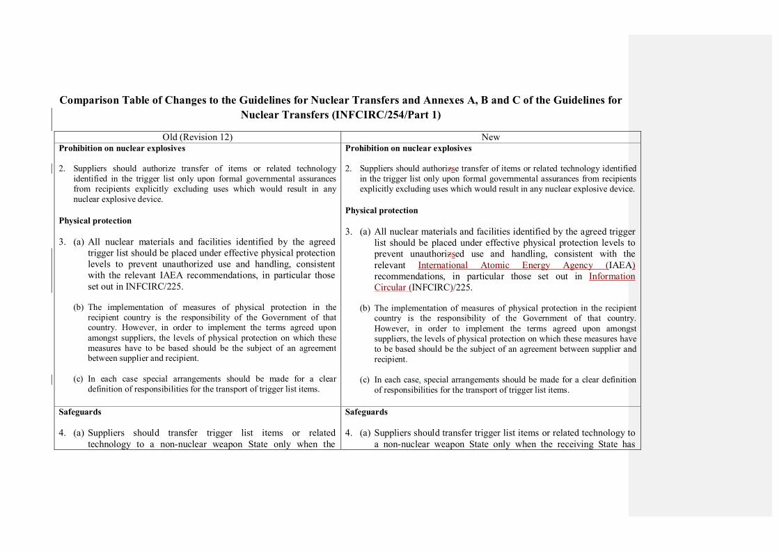
Comparison Table of Changes to the Guidelines for Nuclear Transfers and Annexes A, B and C of the Guidelines for
Nuclear Transfers (INFCIRC/254/Part 1)
Old (Revision 12) New Prohibition on nuclear explosives
2. Suppliers should authorize transfer of items or related technology
identified in the trigger list only upon formal governmental assurances
from recipients explicitly excluding uses which would result in any
nuclear explosive device.
Physical protection
3. (a) All nuclear materials and facilities identified by the agreed
trigger list should be placed under effective physical protection
levels to prevent unauthorized use and handling, consistent
with the relevant IAEA recommendations, in particular those
set out in INFCIRC/225.
(b) The implementation of measures of physical protection in the
recipient country is the responsibility of the Government of that country. However, in order to implement the terms agreed upon
amongst suppliers, the levels of physical protection on which these
measures have to be based should be the subject of an agreement between supplier and recipient.
(c) In each case special arrangements should be made for a clear
definition of responsibilities for the transport of trigger list items.
Prohibition on nuclear explosives
2. Suppliers should authorizse transfer of items or related technology identified
in the trigger list only upon formal governmental assurances from recipients
explicitly excluding uses which would result in any nuclear explosive device.
Physical protection
3. (a) All nuclear materials and facilities identified by the agreed trigger
list should be placed under effective physical protection levels to
prevent unauthorizsed use and handling, consistent with the
relevant International Atomic Energy Agency (IAEA)
recommendations, in particular those set out in Information
Circular (INFCIRC)/225.
(b) The implementation of measures of physical protection in the recipient country is the responsibility of the Government of that country.
However, in order to implement the terms agreed upon amongst
suppliers, the levels of physical protection on which these measures have
to be based should be the subject of an agreement between supplier and
recipient.
(c) In each case, special arrangements should be made for a clear definition
of responsibilities for the transport of trigger list items.
Safeguards
4. (a) Suppliers should transfer trigger list items or related
technology to a non-nuclear weapon State only when the
Safeguards
4. (a) Suppliers should transfer trigger list items or related technology to
a non-nuclear weapon State only when the receiving State has

receiving State has brought into force an agreement with the
IAEA requiring the application of safeguards on all source and
special fissionable material in its current and future peaceful
activities. Suppliers should authorize such transfers only upon
formal governmental assurances from the recipient that:
brought into force an agreement with the IAEA requiring the
application of safeguards on all source and special fissionable
material in its current and future peaceful activities. Suppliers
should authorizse such transfers only upon formal governmental
assurances from the recipient that:
(b) Transfers covered by paragraph 4 (a) to a non-nuclear-weapon
State without such a safeguards agreement should be authorized
only in exceptional cases when they are deemed essential for
the safe operation of existing facilities and if safeguards are
applied to those facilities. Suppliers should inform and, if
appropriate, consult in the event that they intend to authorize or to deny such transfers.
(b) Transfers covered by paragraph 4(a) to a non-nuclear-weapon State
without such a safeguards agreement should be authorizsed only in
exceptional cases when they are deemed essential for the safe
operation of existing facilities and if safeguards are applied to
those facilities. Suppliers should inform and, if appropriate, consult
in the event that they intend to authorizse or to deny such transfers.
(d) Under agreements to which the policy referred to in paragraph 4 (a)
does not apply (see paragraphs 4 (b) and (c)) suppliers should
transfer trigger list items or related technology only when covered by IAEA safeguards with duration and coverage provisions in
conformity with IAEA doc. GOV/1621. However, suppliers
undertake to strive for the earliest possible implementation of the policy referred to in paragraph 4 (a) under such agreements.
(d) Under agreements to which the policy referred to in paragraph 4(a) does
not apply (see paragraphs 4(b) and (c)) suppliers should transfer trigger
list items or related technology only when covered by IAEA safeguards with duration and coverage provisions in conformity with IAEA
document. GOV/1621. However, suppliers undertake to strive for the
earliest possible implementation of the policy referred to in paragraph 4(a) under such agreements.
Special controls on sensitive exports
6. Suppliers should exercise a policy of restraint in the transfer of
sensitive facilities, equipment, technology and material usable for nuclear weapons or other nuclear explosive devices, especially in
cases when a State has on its territory entities that are the object of
active NSG Guidelines Part 2 denial notifications from more than
one NSG Participating Government.
(a) In the context of this policy, suppliers should not authorize the
transfer of enrichment and reprocessing facilities, and
Special controls on sensitive exports
6. Suppliers should exercise a policy of restraint in the transfer of
sensitive facilities, equipment, technology and material usable for nuclear weapons or other nuclear explosive devices, especially in cases
when a State has on its territory entities that are the object of active
Nuclear Suppliers Group (NSG)NSG Guidelines Part 2 denial
notifications from more than one NSG Participating Government.
(a) In the context of this policy, suppliers should not authorizse the
transfer of enrichment and reprocessing facilities, and equipment
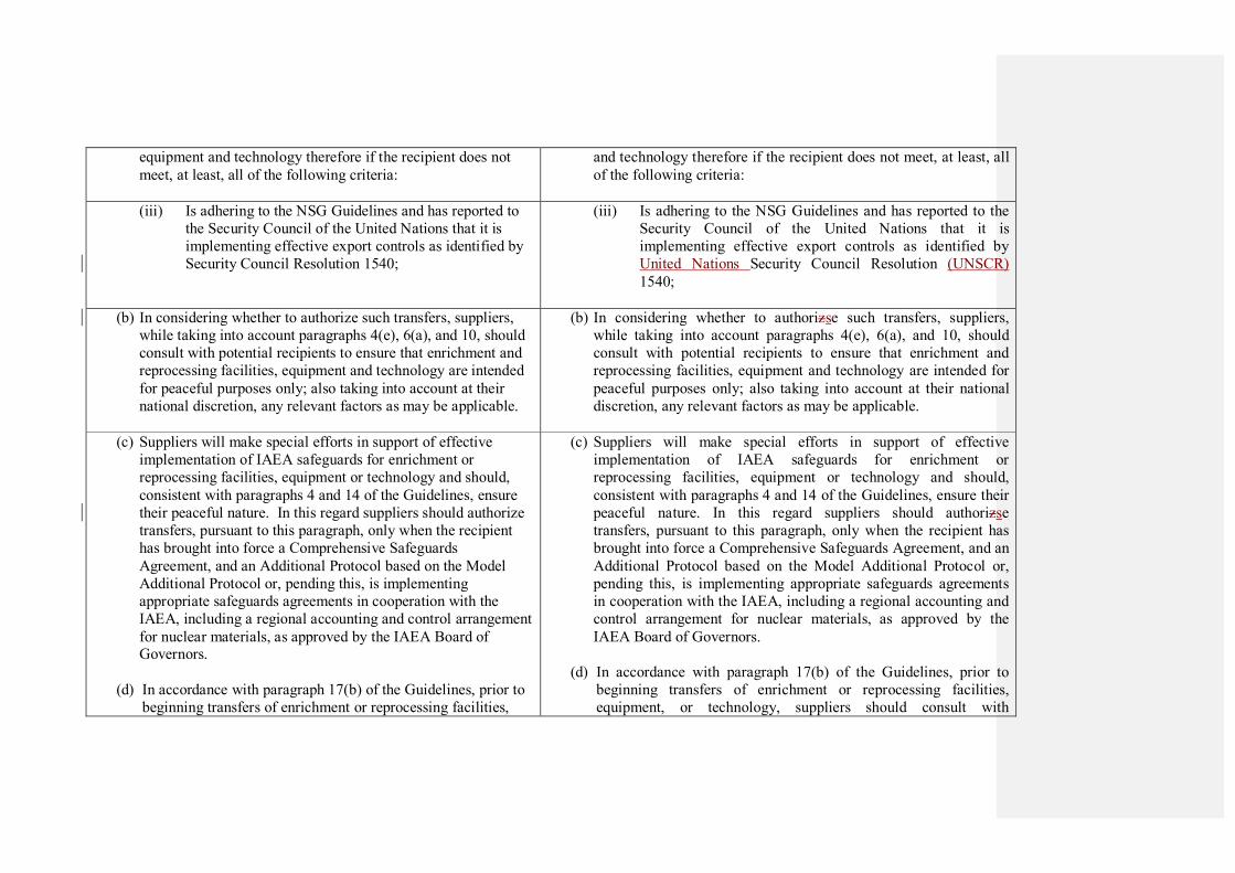
equipment and technology therefore if the recipient does not
meet, at least, all of the following criteria:
and technology therefore if the recipient does not meet, at least, all
of the following criteria:
(iii) Is adhering to the NSG Guidelines and has reported to
the Security Council of the United Nations that it is
implementing effective export controls as identified by
Security Council Resolution 1540;
(iii) Is adhering to the NSG Guidelines and has reported to the
Security Council of the United Nations that it is
implementing effective export controls as identified by
United Nations Security Council Resolution (UNSCR)
1540;
(b) In considering whether to authorize such transfers, suppliers,
while taking into account paragraphs 4(e), 6(a), and 10, should
consult with potential recipients to ensure that enrichment and
reprocessing facilities, equipment and technology are intended
for peaceful purposes only; also taking into account at their
national discretion, any relevant factors as may be applicable.
(b) In considering whether to authorizse such transfers, suppliers,
while taking into account paragraphs 4(e), 6(a), and 10, should
consult with potential recipients to ensure that enrichment and
reprocessing facilities, equipment and technology are intended for
peaceful purposes only; also taking into account at their national
discretion, any relevant factors as may be applicable.
(c) Suppliers will make special efforts in support of effective
implementation of IAEA safeguards for enrichment or
reprocessing facilities, equipment or technology and should,
consistent with paragraphs 4 and 14 of the Guidelines, ensure
their peaceful nature. In this regard suppliers should authorize
transfers, pursuant to this paragraph, only when the recipient
has brought into force a Comprehensive Safeguards
Agreement, and an Additional Protocol based on the Model
Additional Protocol or, pending this, is implementing
appropriate safeguards agreements in cooperation with the
IAEA, including a regional accounting and control arrangement
for nuclear materials, as approved by the IAEA Board of Governors.
(d) In accordance with paragraph 17(b) of the Guidelines, prior to
beginning transfers of enrichment or reprocessing facilities,
(c) Suppliers will make special efforts in support of effective
implementation of IAEA safeguards for enrichment or
reprocessing facilities, equipment or technology and should,
consistent with paragraphs 4 and 14 of the Guidelines, ensure their
peaceful nature. In this regard suppliers should authorizse
transfers, pursuant to this paragraph, only when the recipient has
brought into force a Comprehensive Safeguards Agreement, and an
Additional Protocol based on the Model Additional Protocol or,
pending this, is implementing appropriate safeguards agreements
in cooperation with the IAEA, including a regional accounting and
control arrangement for nuclear materials, as approved by the
IAEA Board of Governors.
(d) In accordance with paragraph 17(b) of the Guidelines, prior to
beginning transfers of enrichment or reprocessing facilities,
equipment, or technology, suppliers should consult with
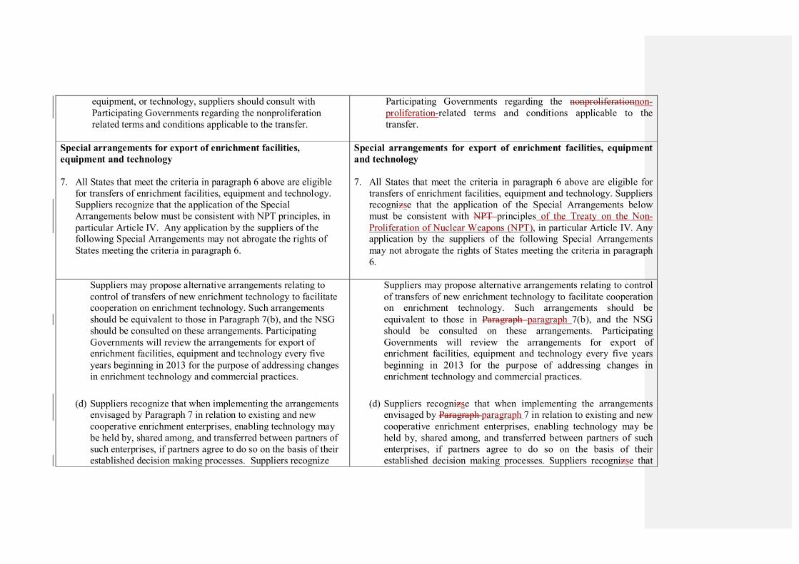
equipment, or technology, suppliers should consult with
Participating Governments regarding the nonproliferation
related terms and conditions applicable to the transfer.
Participating Governments regarding the nonproliferationnon-
proliferation-related terms and conditions applicable to the
transfer.
Special arrangements for export of enrichment facilities,
equipment and technology
7. All States that meet the criteria in paragraph 6 above are eligible
for transfers of enrichment facilities, equipment and technology.
Suppliers recognize that the application of the Special
Arrangements below must be consistent with NPT principles, in
particular Article IV. Any application by the suppliers of the following Special Arrangements may not abrogate the rights of
States meeting the criteria in paragraph 6.
Special arrangements for export of enrichment facilities, equipment
and technology
7. All States that meet the criteria in paragraph 6 above are eligible for
transfers of enrichment facilities, equipment and technology. Suppliers
recognizse that the application of the Special Arrangements below
must be consistent with NPT principles of the Treaty on the Non-
Proliferation of Nuclear Weapons (NPT), in particular Article IV. Any application by the suppliers of the following Special Arrangements
may not abrogate the rights of States meeting the criteria in paragraph
6.
Suppliers may propose alternative arrangements relating to
control of transfers of new enrichment technology to facilitate cooperation on enrichment technology. Such arrangements
should be equivalent to those in Paragraph 7(b), and the NSG
should be consulted on these arrangements. Participating
Governments will review the arrangements for export of enrichment facilities, equipment and technology every five
years beginning in 2013 for the purpose of addressing changes
in enrichment technology and commercial practices.
(d) Suppliers recognize that when implementing the arrangements envisaged by Paragraph 7 in relation to existing and new
cooperative enrichment enterprises, enabling technology may
be held by, shared among, and transferred between partners of
such enterprises, if partners agree to do so on the basis of their
established decision making processes. Suppliers recognize
Suppliers may propose alternative arrangements relating to control
of transfers of new enrichment technology to facilitate cooperation on enrichment technology. Such arrangements should be
equivalent to those in Paragraph paragraph 7(b), and the NSG
should be consulted on these arrangements. Participating
Governments will review the arrangements for export of enrichment facilities, equipment and technology every five years
beginning in 2013 for the purpose of addressing changes in
enrichment technology and commercial practices.
(d) Suppliers recognizse that when implementing the arrangements envisaged by Paragraph paragraph 7 in relation to existing and new
cooperative enrichment enterprises, enabling technology may be
held by, shared among, and transferred between partners of such
enterprises, if partners agree to do so on the basis of their
established decision making processes. Suppliers recognizse that
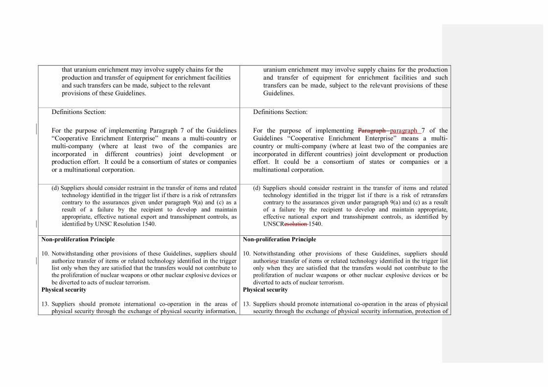
that uranium enrichment may involve supply chains for the
production and transfer of equipment for enrichment facilities
and such transfers can be made, subject to the relevant
provisions of these Guidelines.
uranium enrichment may involve supply chains for the production
and transfer of equipment for enrichment facilities and such
transfers can be made, subject to the relevant provisions of these
Guidelines.
Definitions Section:
For the purpose of implementing Paragraph 7 of the Guidelines
“Cooperative Enrichment Enterprise” means a multi-country or
multi-company (where at least two of the companies are
incorporated in different countries) joint development or production effort. It could be a consortium of states or companies
or a multinational corporation.
Definitions Section:
For the purpose of implementing Paragraph paragraph 7 of the
Guidelines “Cooperative Enrichment Enterprise” means a multi-
country or multi-company (where at least two of the companies are
incorporated in different countries) joint development or production effort. It could be a consortium of states or companies or a
multinational corporation.
(d) Suppliers should consider restraint in the transfer of items and related
technology identified in the trigger list if there is a risk of retransfers
contrary to the assurances given under paragraph 9(a) and (c) as a
result of a failure by the recipient to develop and maintain
appropriate, effective national export and transshipment controls, as
identified by UNSC Resolution 1540.
(d) Suppliers should consider restraint in the transfer of items and related
technology identified in the trigger list if there is a risk of retransfers
contrary to the assurances given under paragraph 9(a) and (c) as a result
of a failure by the recipient to develop and maintain appropriate,
effective national export and transshipment controls, as identified by
UNSCResolution 1540.
Non-proliferation Principle
10. Notwithstanding other provisions of these Guidelines, suppliers should
authorize transfer of items or related technology identified in the trigger list only when they are satisfied that the transfers would not contribute to
the proliferation of nuclear weapons or other nuclear explosive devices or
be diverted to acts of nuclear terrorism.
Physical security
13. Suppliers should promote international co-operation in the areas of
physical security through the exchange of physical security information,
Non-proliferation Principle
10. Notwithstanding other provisions of these Guidelines, suppliers should
authorizse transfer of items or related technology identified in the trigger list only when they are satisfied that the transfers would not contribute to the
proliferation of nuclear weapons or other nuclear explosive devices or be
diverted to acts of nuclear terrorism.
Physical security
13. Suppliers should promote international co-operation in the areas of physical
security through the exchange of physical security information, protection of

protection of nuclear materials in transit, and recovery of stolen nuclear
materials and equipment. Suppliers should promote broadest adherence to the respective international instruments, inter alia, to the Convention on
the Physical Protection of Nuclear Material, as well as implementation of
INFCIRC/225, as amended from time to time. Suppliers recognize the
importance of these activities and other relevant IAEA activities in
preventing the proliferation of nuclear weapons and countering the threat
of nuclear terrorism.
nuclear materials in transit, and recovery of stolen nuclear materials and
equipment. Suppliers should promote broadest adherence to the respective international instruments, inter alia, to the Convention on the Physical
Protection of Nuclear Material, as well as implementation of INFCIRC/225,
as amended from time to time. Suppliers recognizse the importance of these
activities and other relevant IAEA activities in preventing the proliferation of
nuclear weapons and countering the threat of nuclear terrorism.
Support for effective IAEA safeguards
14. Suppliers should make special efforts in support of effective
implementation of IAEA safeguards. Suppliers should also support the
Agency's efforts to assist Member States in the improvement of their
national systems of accounting and control of nuclear material and to
increase the technical effectiveness of safeguards.
Support for effective IAEA safeguards
14. Suppliers should make special efforts in support of effective implementation
of IAEA safeguards. Suppliers should also support the Agency's IAEA's
efforts to assist Member States in the improvement of their national systems
of accounting and control of nuclear material and to increase the technical
effectiveness of safeguards.
Trigger list plant design features
15. Suppliers should encourage the designers and makers of trigger list
facilities to construct them in such a way as to facilitate the application of
safeguards and to enhance physical protection, taking also into
consideration the risk of terrorist attacks. Suppliers should promote protection of information on the design of trigger list installations, and
stress to recipients the necessity of doing so. Suppliers also recognize the
importance of including safety and non-proliferation features in designing and construction of trigger list facilities.
Trigger list plant design features
15. Suppliers should encourage the designers and makers of trigger list facilities
to construct them in such a way as to facilitate the application of safeguards
and to enhance physical protection, taking also into consideration the risk of
terrorist attacks. Suppliers should promote protection of information on the design of trigger list installations, and stress to recipients the necessity of
doing so. Suppliers also recognizse the importance of including safety and
non-proliferation features in designing and construction of trigger list facilities.
Export Controls
16. Suppliers should, where appropriate, stress to recipients the need to
subject transferred trigger list items and related technology and trigger
list items derived from facilities originally transferred by the supplier or with the help of equipment or technology originally transferred by the
supplier to export controls as outlined in UNSC Resolution 1540.
Export Controls
16. Suppliers should, where appropriate, stress to recipients the need to subject
transferred trigger list items and related technology and trigger list items
derived from facilities originally transferred by the supplier or with the help of equipment or technology originally transferred by the supplier to export
controls as outlined in UNSCResolution 1540. Suppliers are encouraged to
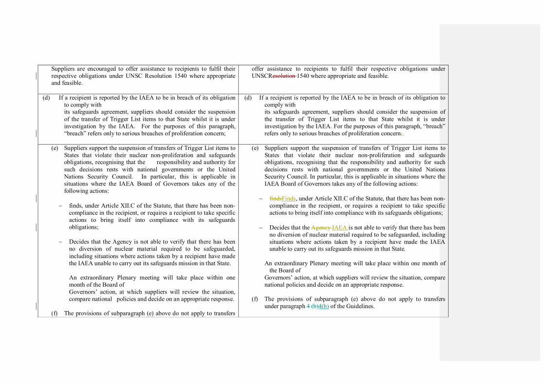
Suppliers are encouraged to offer assistance to recipients to fulfil their
respective obligations under UNSC Resolution 1540 where appropriate and feasible.
offer assistance to recipients to fulfil their respective obligations under
UNSCResolution 1540 where appropriate and feasible.
(d) If a recipient is reported by the IAEA to be in breach of its obligation
to comply with its safeguards agreement, suppliers should consider the suspension
of the transfer of Trigger List items to that State whilst it is under
investigation by the IAEA. For the purposes of this paragraph,
“breach” refers only to serious breaches of proliferation concern;
(d) If a recipient is reported by the IAEA to be in breach of its obligation to
comply with its safeguards agreement, suppliers should consider the suspension of
the transfer of Trigger List items to that State whilst it is under
investigation by the IAEA. For the purposes of this paragraph, “breach”
refers only to serious breaches of proliferation concern;.
(e) Suppliers support the suspension of transfers of Trigger List items to
States that violate their nuclear non-proliferation and safeguards obligations, recognising that the responsibility and authority for
such decisions rests with national governments or the United
Nations Security Council. In particular, this is applicable in
situations where the IAEA Board of Governors takes any of the
following actions:
− finds, under Article XII.C of the Statute, that there has been non-
compliance in the recipient, or requires a recipient to take specific
actions to bring itself into compliance with its safeguards
obligations;
− Decides that the Agency is not able to verify that there has been
no diversion of nuclear material required to be safeguarded,
including situations where actions taken by a recipient have made
the IAEA unable to carry out its safeguards mission in that State.
An extraordinary Plenary meeting will take place within one
month of the Board of
Governors’ action, at which suppliers will review the situation,
compare national policies and decide on an appropriate response.
(f) The provisions of subparagraph (e) above do not apply to transfers
(e) Suppliers support the suspension of transfers of Trigger List items to
States that violate their nuclear non-proliferation and safeguards obligations, recognising that the responsibility and authority for such
decisions rests with national governments or the United Nations
Security Council. In particular, this is applicable in situations where the
IAEA Board of Governors takes any of the following actions:
− findsFinds, under Article XII.C of the Statute, that there has been non-
compliance in the recipient, or requires a recipient to take specific
actions to bring itself into compliance with its safeguards obligations;
− Decides that the Agency IAEA is not able to verify that there has been
no diversion of nuclear material required to be safeguarded, including
situations where actions taken by a recipient have made the IAEA unable to carry out its safeguards mission in that State.
An extraordinary Plenary meeting will take place within one month of
the Board of
Governors’ action, at which suppliers will review the situation, compare
national policies and decide on an appropriate response.
(f) The provisions of subparagraph (e) above do not apply to transfers
under paragraph 4 (b)4(b) of the Guidelines.
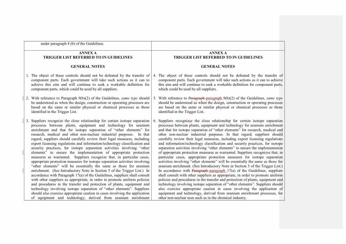
under paragraph 4 (b) of the Guidelines.
ANNEX A
TRIGGER LIST REFERRED TO IN GUIDELINES
GENERAL NOTES
1. The object of these controls should not be defeated by the transfer of
component parts. Each government will take such actions as it can to
achieve this aim and will continue to seek a workable definition for
component parts, which could be used by all suppliers.
2. With reference to Paragraph 9(b)(2) of the Guidelines, same type should
be understood as when the design, construction or operating processes are
based on the same or similar physical or chemical processes as those
identified in the Trigger List.
3. Suppliers recognize the close relationship for certain isotope separation
processes between plants, equipment and technology for uranium
enrichment and that for isotope separation of “other elements” for research, medical and other non-nuclear industrial purposes. In that
regard, suppliers should carefully review their legal measures, including
export licensing regulations and information/technology classification and security practices, for isotope separation activities involving “other
elements” to ensure the implementation of appropriate protection
measures as warranted. Suppliers recognize that, in particular cases, appropriate protection measures for isotope separation activities involving
“other elements” will be essentially the same as those for uranium
enrichment. (See Introductory Note in Section 5 of the Trigger List.) In
accordance with Paragraph 17(a) of the Guidelines, suppliers shall consult with other suppliers as appropriate, in order to promote uniform policies
and procedures in the transfer and protection of plants, equipment and
technology involving isotope separation of “other elements”. Suppliers should also exercise appropriate caution in cases involving the application
of equipment and technology, derived from uranium enrichment
ANNEX A
TRIGGER LIST REFERRED TO IN GUIDELINES
GENERAL NOTES
4. The object of these controls should not be defeated by the transfer of
component parts. Each government will take such actions as it can to achieve
this aim and will continue to seek a workable definition for component parts,
which could be used by all suppliers.
5. With reference to Paragraph paragraph 9(b)(2) of the Guidelines, same type
should be understood as when the design, construction or operating processes
are based on the same or similar physical or chemical processes as those
identified in the Trigger List.
6. Suppliers recognizse the close relationship for certain isotope separation
processes between plants, equipment and technology for uranium enrichment
and that for isotope separation of “other elements” for research, medical and other non-nuclear industrial purposes. In that regard, suppliers should
carefully review their legal measures, including export licensing regulations
and information/technology classification and security practices, for isotope separation activities involving “other elements” to ensure the implementation
of appropriate protection measures as warranted. Suppliers recognizse that, in
particular cases, appropriate protection measures for isotope separation activities involving “other elements” will be essentially the same as those for
uranium enrichment. (See Introductory Note in Section 5 of the Trigger List.)
In accordance with Paragraph paragraph 17(a) of the Guidelines, suppliers
shall consult with other suppliers as appropriate, in order to promote uniform policies and procedures in the transfer and protection of plants, equipment and
technology involving isotope separation of “other elements”. Suppliers should
also exercise appropriate caution in cases involving the application of equipment and technology, derived from uranium enrichment processes, for
other non-nuclear uses such as in the chemical industry.
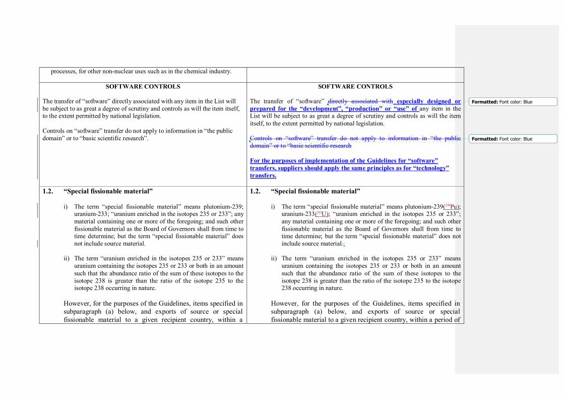
processes, for other non-nuclear uses such as in the chemical industry.
SOFTWARE CONTROLS
The transfer of “software” directly associated with any item in the List will
be subject to as great a degree of scrutiny and controls as will the item itself, to the extent permitted by national legislation.
Controls on “software” transfer do not apply to information in “the public
domain” or to “basic scientific research”.
SOFTWARE CONTROLS
The transfer of “software” directly associated with especially designed or
prepared for the “development”, “production” or “use” of any item in the List will be subject to as great a degree of scrutiny and controls as will the item
itself, to the extent permitted by national legislation.
Controls on “software” transfer do not apply to information in “the public
domain” or to “basic scientific research
For the purposes of implementation of the Guidelines for “software”
transfers, suppliers should apply the same principles as for “technology”
transfers.
1.2. “Special fissionable material”
i) The term “special fissionable material” means plutonium-239;
uranium-233; “uranium enriched in the isotopes 235 or 233”; any
material containing one or more of the foregoing; and such other
fissionable material as the Board of Governors shall from time to time determine; but the term “special fissionable material” does
not include source material.
ii) The term “uranium enriched in the isotopes 235 or 233” means
uranium containing the isotopes 235 or 233 or both in an amount
such that the abundance ratio of the sum of these isotopes to the
isotope 238 is greater than the ratio of the isotope 235 to the isotope 238 occurring in nature.
However, for the purposes of the Guidelines, items specified in
subparagraph (a) below, and exports of source or special
fissionable material to a given recipient country, within a
1.2. “Special fissionable material”
i) The term “special fissionable material” means plutonium-239(239Pu);
uranium-233(233U); “uranium enriched in the isotopes 235 or 233”;
any material containing one or more of the foregoing; and such other
fissionable material as the Board of Governors shall from time to time determine; but the term “special fissionable material” does not
include source material.;
ii) The term “uranium enriched in the isotopes 235 or 233” means
uranium containing the isotopes 235 or 233 or both in an amount
such that the abundance ratio of the sum of these isotopes to the
isotope 238 is greater than the ratio of the isotope 235 to the isotope 238 occurring in nature.
However, for the purposes of the Guidelines, items specified in
subparagraph (a) below, and exports of source or special
fissionable material to a given recipient country, within a period of
Formatted: Font color: Blue
Formatted: Font color: Blue
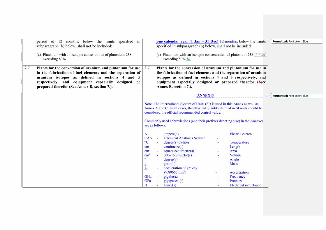
period of 12 months, below the limits specified in
subparagraph (b) below, shall not be included:
(a) Plutonium with an isotopic concentration of plutonium-238
exceeding 80%.
one calendar year (1 Jan – 31 Dec) 12 months, below the limits
specified in subparagraph (b) below, shall not be included:
(a) Plutonium with an isotopic concentration of plutonium-238 (238PUu)
exceeding 80%.%;
2.7. Plants for the conversion of uranium and plutonium for use
in the fabrication of fuel elements and the separation of
uranium isotopes as defined in sections 4 and 5
respectively, and equipment especially designed or
prepared therefor (See Annex B, section 7.).
2.7. Plants for the conversion of uranium and plutonium for use in
the fabrication of fuel elements and the separation of uranium
isotopes as defined in sections 4 and 5 respectively, and
equipment especially designed or prepared therefor (Ssee
Annex B, section 7.).
ANNEX B
Note: The International System of Units (SI) is used in this Annex as well as
Annex A and C. In all cases, the physical quantity defined in SI units should be
considered the official recommended control value.
Commonly used abbreviations (and their prefixes denoting size) in the Annexes
are as follows:
A - ampere(s) - Electric current CAS - Chemical Abstracts Service -
°C - degree(s) Celsius - Temperature
cm - centimetre(s) - Length cm2 - square centimetre(s) - Area
cm3 - cubic centimetre(s) - Volume
° - degree(s) - Angle g - gram(s) - Mass
g0 - acceleration of gravity
(9.80665 m/s2) - Acceleration
GHz - gigahertz - Frequency GPa - gigapascal(s) - Pressure
H - henry(s) - Electrical inductance
Formatted: Font color: Blue
Formatted: Font color: Blue

h - hour(s) - Time
Hz - hertz - Frequency kg - kilogram(s) - Mass
kHz - kilohertz - Frequency
kJ - kilojoule(s) - Energy, work, heat
kPa - kilopascal(s) - Pressure
kW - kilowatt(s) - Power
K - kelvin - Thermodynamic
temperature
m - metre(s) - Length
m2 - square metre(s) - Area
m3 - cubic metre(s) - Volume
mA - milliampere(s) - Electric current min - minute(s) - Time
MPa - megapascal(s) - Pressure
mm - millimetre(s) - Length µm - micrometre(s) - Length
N - newton(s) - Force
nm - nanometre(s) - Length Ω - ohm(s) - Electric resistance
Pa - pascal(s) - Pressure
s - second(s) - Time
" - second(s) of arc - Angle V - volt(s) - Electrical potential
VA - volt-ampere(s) - Electric power
ANNEX B
CLARIFICATION OF ITEMS ON THE TRIGGER LIST
(as designated in Section 2 of MATERIAL AND EQUIPMENT of Annex
A)
1. Nuclear reactors and especially designed or prepared
equipment and components therefor
ANNEX B
CLARIFICATION OF ITEMS ON THE TRIGGER LIST
(as designated in Section 2 of MATERIAL AND EQUIPMENT of Annex A)
1. Nuclear reactors and especially designed or prepared
equipment and components therefor
INTRODUCTORY NOTE
Formatted: Font color: Blue
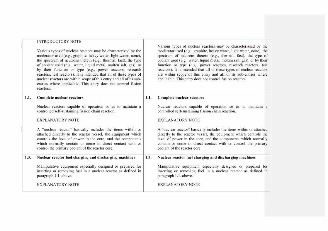
INTRODUCTORY NOTE
Various types of nuclear reactors may be characterized by the
moderator used (e.g., graphite, heavy water, light water, none),
the spectrum of neutrons therein (e.g., thermal, fast), the type
of coolant used (e.g., water, liquid metal, molten salt, gas), or by their function or type (e.g., power reactors, research
reactors, test reactors). It is intended that all of these types of
nuclear reactors are within scope of this entry and all of its sub-
entries where applicable. This entry does not control fusion
reactors.
Various types of nuclear reactors may be characterizsed by the
moderator used (e.g., graphite, heavy water, light water, none), the
spectrum of neutrons therein (e.g., thermal, fast), the type of
coolant used (e.g., water, liquid metal, molten salt, gas), or by their
function or type (e.g., power reactors, research reactors, test reactors). It is intended that all of these types of nuclear reactors
are within scope of this entry and all of its sub-entries where
applicable. This entry does not control fusion reactors.
1.1. Complete nuclear reactors
Nuclear reactors capable of operation so as to maintain a
controlled self-sustaining fission chain reaction.
EXPLANATORY NOTE
A “nuclear reactor” basically includes the items within or
attached directly to the reactor vessel, the equipment which
controls the level of power in the core, and the components
which normally contain or come in direct contact with or
control the primary coolant of the reactor core.
1.1. Complete nuclear reactors
Nuclear reactors capable of operation so as to maintain a
controlled self-sustaining fission chain reaction.
EXPLANATORY NOTE
A “nuclear reactor” basically includes the items within or attached
directly to the reactor vessel, the equipment which controls the
level of power in the core, and the components which normally
contain or come in direct contact with or control the primary
coolant of the reactor core.
1.3. Nuclear reactor fuel charging and discharging machines
Manipulative equipment especially designed or prepared for
inserting or removing fuel in a nuclear reactor as defined in
paragraph 1.1. above.
EXPLANATORY NOTE
1.3. Nuclear reactor fuel charging and discharging machines
Manipulative equipment especially designed or prepared for
inserting or removing fuel in a nuclear reactor as defined in
paragraph 1.1. above.
EXPLANATORY NOTE
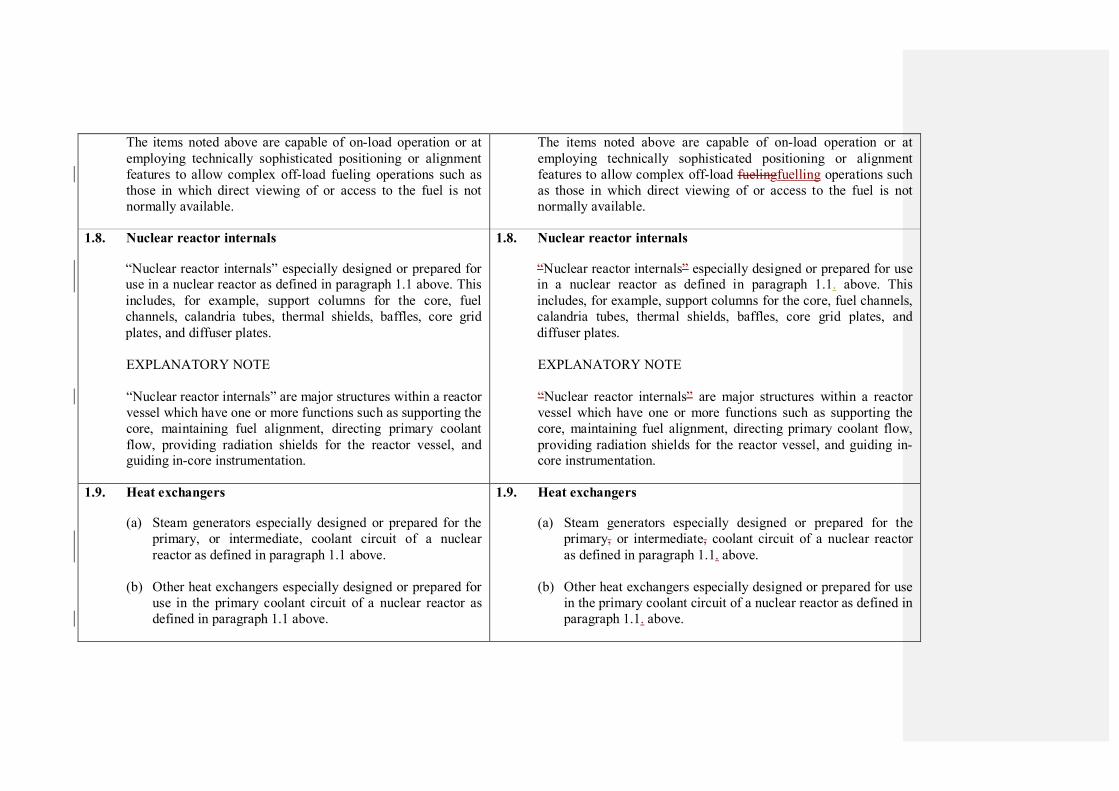
The items noted above are capable of on-load operation or at
employing technically sophisticated positioning or alignment
features to allow complex off-load fueling operations such as
those in which direct viewing of or access to the fuel is not
normally available.
The items noted above are capable of on-load operation or at
employing technically sophisticated positioning or alignment
features to allow complex off-load fuelingfuelling operations such
as those in which direct viewing of or access to the fuel is not
normally available.
1.8. Nuclear reactor internals
“Nuclear reactor internals” especially designed or prepared for use in a nuclear reactor as defined in paragraph 1.1 above. This
includes, for example, support columns for the core, fuel
channels, calandria tubes, thermal shields, baffles, core grid
plates, and diffuser plates.
EXPLANATORY NOTE
“Nuclear reactor internals” are major structures within a reactor
vessel which have one or more functions such as supporting the
core, maintaining fuel alignment, directing primary coolant
flow, providing radiation shields for the reactor vessel, and guiding in-core instrumentation.
1.8. Nuclear reactor internals
“Nuclear reactor internals” especially designed or prepared for use in a nuclear reactor as defined in paragraph 1.1. above. This
includes, for example, support columns for the core, fuel channels,
calandria tubes, thermal shields, baffles, core grid plates, and
diffuser plates.
EXPLANATORY NOTE
“Nuclear reactor internals” are major structures within a reactor
vessel which have one or more functions such as supporting the
core, maintaining fuel alignment, directing primary coolant flow,
providing radiation shields for the reactor vessel, and guiding in-core instrumentation.
1.9. Heat exchangers
(a) Steam generators especially designed or prepared for the
primary, or intermediate, coolant circuit of a nuclear
reactor as defined in paragraph 1.1 above.
(b) Other heat exchangers especially designed or prepared for
use in the primary coolant circuit of a nuclear reactor as
defined in paragraph 1.1 above.
1.9. Heat exchangers
(a) Steam generators especially designed or prepared for the
primary, or intermediate, coolant circuit of a nuclear reactor
as defined in paragraph 1.1. above.
(b) Other heat exchangers especially designed or prepared for use
in the primary coolant circuit of a nuclear reactor as defined in
paragraph 1.1. above.

EXPLANATORY NOTE
Steam generators are especially designed or prepared to
transfer the heat generated in the reactor to the feed water for
steam generation. In the case of a fast reactor for which an
intermediate coolant loop is also present, the steam generator is in the intermediate circuit.
In a gas-cooled reactor, a heat exchanger may be utilized to
transfer heat to a secondary gas loop that drives a gas turbine.
The scope of control for this entry does not include heat
exchangers for the supporting systems of the reactor, e.g., the
emergency cooling system or the decay heat cooling system.
EXPLANATORY NOTE
Steam generators are especially designed or prepared to transfer
the heat generated in the reactor to the feed water for steam
generation. In the case of a fast reactor for which an intermediate
coolant loop is also present, the steam generator is in the intermediate circuit.
In a gas-cooled reactor, a heat exchanger may be utilizsed to
transfer heat to a secondary gas loop that drives a gas turbine.
The scope of control for this entry does not include heat
exchangers for the supporting systems of the reactor, (e.g., the
emergency cooling system or the decay heat cooling system).
1.10. Neutron detectors
Especially designed or prepared neutron detectors for
determining neutron flux levels within the core of a reactor as
defined in paragraph 1.1. above. EXPLANATORY NOTE
The scope of this entry encompasses in-core and ex-core
detectors which measure flux levels in a large range, typically from 10
4 neutrons per cm
2 per second to 10
10 neutrons per cm
2
per second or more. Ex-core refers to those instruments outside
the core of a reactor as defined in paragraph 1.1. above, but
located within the biological shielding.
1.10. Neutron detectors
Especially designed or prepared neutron detectors for determining
neutron flux levels within the core of a reactor as defined in
paragraph 1.1. above. EXPLANATORY NOTE
The scope of this entry encompasses in-core and ex-core detectors
which measure flux levels in a widelarge range, typically from 104
neutrons per cm2 per second to 10
10 neutrons per cm
2 per second
or more. Ex-core refers to those instruments outside the core of a
reactor as defined in paragraph 1.1. above, but located within the
biological shielding.
1.11. External thermal shields
“External thermal shields” especially designed or prepared for
1.11. External thermal shields
“External thermal shields” especially designed or prepared for use
Formatted: Font color: Blue
Formatted: Font color: Blue

use in a nuclear reactor as defined in paragraph 1.1 for
reduction of heat loss and also for containment vessel
protection.
EXPLANATORY NOTE
“External thermal shields” are major structures placed over the
reactor vessel which reduce heat loss from the reactor and
reduce temperature within the containment vessel.
in a nuclear reactor as defined in paragraph 1.1. for reduction of
heat loss and also for containment vessel protection.
EXPLANATORY NOTE
“External thermal shields” are major structures placed over the reactor vessel which reduce heat loss from the reactor and reduce
temperature within the containment vessel.
2.1. Deuterium and heavy water
Deuterium, heavy water (deuterium oxide) and any other deuterium compound in which the ratio of deuterium to
hydrogen atoms exceeds 1:5000 for use in a nuclear reactor as
defined in paragraph 1.1. above in quantities exceeding 200 kg
of deuterium atoms for any one recipient country in any period
of 12 months.
2.1. Deuterium and heavy water
Deuterium, heavy water (deuterium oxide) and any other deuterium compound in which the ratio of deuterium to hydrogen
atoms exceeds 1:5000 for use in a nuclear reactor as defined in
paragraph 1.1. above in quantities exceeding 200 kg of deuterium
atoms for any one recipient country within a period of one
calendar year (1 Jan – 31 Dec) in any period of 12 months.
2.2. Nuclear grade graphite
Graphite having a purity level better than 5 parts per million
boron equivalent and with a density greater than 1.50 g/cm3 for
use in a nuclear reactor as defined in paragraph 1.1 above, in
quantities exceeding 1 kilogram.
EXPLANATORY NOTE
For the purpose of export control, the Government will
determine whether or not the exports of graphite meeting the above specifications are for nuclear reactor use.
2.2. Nuclear grade graphite
Graphite having a purity level better than 5 ppm (parts per million)
boron equivalent and with a density greater than 1.50 g/cm3 for use
in a nuclear reactor as defined in paragraph 1.1. above, in
quantities exceeding 1 kilogramkg.
EXPLANATORY NOTE
For the purpose of export control, the Government will determine
whether or not the exports of graphite meeting the above specifications are for nuclear reactor use.
Formatted: Font color: Blue
Boron equivalent (BE) may be determined experimentally or is
calculated as the sum of BEz for impurities (excluding BEcarbon
since carbon is not considered an impurity) including boron,
where:
BEz (ppm) = CF x concentration of element Z (in ppm);
Boron Eequivalent (BE) may be determined experimentally or is
calculated as the sum of BEz for impurities (excluding BEcarbon
since carbon is not considered an impurity) including boron,
where:
BEz ppm (ppm) = CF x concentration of element Z (in ppm);
3. Plants for the reprocessing of irradiated fuel elements, and
equipment especially designed or prepared therefor
…..
Purex facilities have process functions similar to each other,
including: irradiated fuel element chopping, fuel dissolution,
solvent extraction, and process liquor storage. There may also
be equipment for thermal denitration of uranium nitrate,
conversion of plutonium nitrate to oxide or metal, and
treatment of fission product waste liquor to a form suitable for long term storage or disposal. However, the specific type and
configuration of the equipment performing these functions may
differ between Purex facilities for several reasons, including
the type and quantity of irradiated nuclear fuel to be reprocessed and the intended disposition of the recovered
materials, and the safety and maintenance philosophy
incorporated into the design of the facility.
A “plant for the reprocessing of irradiated fuel elements”,
includes the equipment and components which normally come
in direct contact with and directly control the irradiated fuel
and the major nuclear material and fission product processing
streams.
These processes, including the complete systems for plutonium
3. Plants for the reprocessing of irradiated fuel elements, and
equipment especially designed or prepared therefor
…..
Purex facilities have process functions similar to each other,
including: irradiated fuel element chopping, fuel dissolution,
solvent extraction, and process liquor storage. There may also be
equipment for thermal denitration of uranium nitrate, conversion
of plutonium nitrate to oxide or metal, and treatment of fission
product waste liquor to a form suitable for long term storage or disposal. However, the specific type and configuration of the
equipment performing these functions may differ between Purex
facilities for several reasons, including the type and quantity of
irradiated nuclear fuel to be reprocessed and the intended disposition of the recovered materials, and the safety and
maintenance philosophy incorporated into the design of the
facility.
A “plant for the reprocessing of irradiated fuel elements”, includes
the equipment and components which normally come in direct
contact with and directly control the irradiated fuel and the major
nuclear material and fission product processing streams.
These processes, including the complete systems for plutonium
conversion and plutonium metal production, may be identified by
conversion and plutonium metal production, may be identified
by the measures taken to avoid criticality (e.g. by geometry),
radiation exposure (e.g. by shielding), and toxicity hazards
(e.g. by containment).
the measures taken to avoid criticality (e.g. e.g., by geometry),
radiation exposure (e.g. e.g., by shielding), and toxicity hazards
(e.g. e.g., by containment).
3.2. Dissolvers
Critically safe tanks (e.g. small diameter, annular or slab tanks)
especially designed or prepared for use in a reprocessing plant as identified above, intended for dissolution of irradiated
nuclear fuel and which are capable of withstanding hot, highly
corrosive liquid, and which can be remotely loaded and
maintained.
3.2. Dissolvers
Critically safe tanks (e.g. e.g., small diameter, annular or slab
tanks) especially designed or prepared for use in a reprocessing plant as identified above, intended for dissolution of irradiated
nuclear fuel and which are capable of withstanding hot, highly
corrosive liquid, and which can be remotely loaded and
maintained.
3.3. Solvent extractors and solvent extraction equipment
Especially designed or prepared solvent extractors such as
packed or pulse columns, mixer settlers or centrifugal
contactors for use in a plant for the reprocessing of irradiated
fuel. Solvent extractors must be resistant to the corrosive effect
of nitric acid. Solvent extractors are normally fabricated to
extremely high standards (including special welding and
inspection and quality assurance and quality control
techniques) out of low carbon stainless steels, titanium,
zirconium, or other high quality materials.
3.3. Solvent extractors and solvent extraction equipment
Especially designed or prepared solvent extractors (such as packed
or pulse columns, mixer settlers or centrifugal contactors) for use
in a plant for the reprocessing of irradiated fuel. Solvent extractors
must be resistant to the corrosive effect of nitric acid. Solvent
extractors are normally fabricated to extremely high standards
(including special welding and inspection and quality assurance
and quality control techniques) out of low carbon stainless steels,
titanium, zirconium, or other high quality materials.
3.4. Chemical holding or storage vessels
Especially designed or prepared holding or storage vessels for
use in a plant for the reprocessing of irradiated fuel. The holding or storage vessels must be resistant to the corrosive
effect of nitric acid. The holding or storage vessels are
normally fabricated of materials such as low carbon stainless
3.4. Chemical holding or storage vessels
Especially designed or prepared holding or storage vessels for use
in a plant for the reprocessing of irradiated fuel. The holding or storage vessels must be resistant to the corrosive effect of nitric
acid. The holding or storage vessels are normally fabricated of
materials such as low carbon stainless steels, titanium or

steels, titanium or zirconium, or other high quality materials.
Holding or storage vessels may be designed for remote
operation and maintenance and may have the following
features for control of nuclear criticality:
(1) walls or internal structures with a boron equivalent of at least two per cent, or
(2) a maximum diameter of 175 mm (7 in) for cylindrical vessels,
or
(3) a maximum width of 75 mm (3 in) for either a slab or annular
vessel.
zirconium, or other high quality materials. Holding or storage
vessels may be designed for remote operation and maintenance
and may have the following features for control of nuclear
criticality:
(1.) Wwalls or internal structures with a boron equivalent of at least 2% at least two per cent,; or
(2.) a A maximum diameter of 175 mm (7 in) for cylindrical vessels, ;
or
(3.) a A maximum width of 75 mm (3 in) for either a slab or annular
vessel.
4. Plants for the fabrication of nuclear reactor fuel elements,
and equipment especially designed or prepared therefor
…
Such equipment or systems of equipment may include, for
example:
1) fully automatic pellet inspection stations especially designed or
prepared for checking final dimensions and surface defects of the fuel pellets;
2) automatic welding machines especially designed or prepared for
welding end caps onto the fuel pins (or rods);
3) automatic test and inspection stations especially designed or
prepared for checking the integrity of completed fuel pins (or rods);
4. Plants for the fabrication of nuclear reactor fuel elements, and
equipment especially designed or prepared therefor
…
Such equipment or systems of equipment may include, for
example:
1). fFully automatic pellet inspection stations especially designed or
prepared for checking final dimensions and surface defects of the fuel pellets;
2). aAutomatic welding machines especially designed or prepared for
welding end caps onto the fuel pins (or rods);
3). aAutomatic test and inspection stations especially designed or
prepared for checking the integrity of completed fuel pins (or rods);
4). sSystems especially designed or prepared to manufacture nuclear

4) systems especially designed or prepared to manufacture nuclear
fuel cladding.
Item 3 typically includes equipment for: a) x-ray examination of
pin (or rod) end cap welds, b) helium leak detection from
pressurized pins (or rods), and c) gamma-ray scanning of the
pins (or rods) to check for correct loading of the fuel pellets
inside.
fuel cladding.
Item 3 typically includes equipment for:
(a) xX-ray examination of pin (or rod) end cap welds;
, (b) hHelium leak detection from pressurizsed pins (or rods), );
(c) and c) gGamma-ray scanning of the pins (or rods) to check for correct
loading of the fuel pellets inside.
5.1. Gas centrifuges and assemblies and components
especially designed or prepared for use in gas centrifuges
INTRODUCTORY NOTE
The gas centrifuge normally consists of a thin-walled cylinder(s) of between 75 mm and 650 mm diameter
contained in a vacuum environment and spun at high
peripheral speed of the order of 300 m/s or more with its
central axis vertical. In order to achieve high speed the
materials of construction for the rotating components have
to be of a high strength to density ratio and the rotor
assembly, and hence its individual components, have to be
manufactured to very close tolerances in order to minimize
the unbalance. In contrast to other centrifuges, the gas
centrifuge for uranium enrichment is characterized by having within the rotor chamber a rotating disc-shaped
baffle(s) and a stationary tube arrangement for feeding and
extracting the UF6 gas and featuring at least three separate
channels, of which two are connected to scoops extending from the rotor axis towards the periphery of the rotor
chamber. Also contained within the vacuum environment
5.1. Gas centrifuges and assemblies and components especially
designed or prepared for use in gas centrifuges
INTRODUCTORY NOTE
The gas centrifuge normally consists of a thin-walled cylinder(s) of between 75 mm and 650 mm diameter contained in a vacuum
environment and spun at high peripheral speed of the order of 300
metres per /secondm/s or more with its central axis vertical. In order
to achieve high speed the materials of construction for the rotating
components have to be of a high strength to density ratio and the
rotor assembly, and hence its individual components, have to be
manufactured to very close tolerances in order to minimizse the
unbalance. In contrast to other centrifuges, the gas centrifuge for
uranium enrichment is characterizsed by having within the rotor
chamber a rotating disc-shaped baffle (or baffles) and a stationary tube arrangement for feeding and extracting the uUranium
hHexafluoride (UF6 )) gas and featuring at least three separate
channels, of which two are connected to scoops extending from the
rotor axis towards the periphery of the rotor chamber. Also contained within the vacuum environment are a number of critical items which
do not rotate and, which although they are especially designed, are
are a number of critical items which do not rotate and which
although they are especially designed are not difficult to
fabricate nor are they fabricated out of unique materials. A
centrifuge facility however requires a large number of these
components, so that quantities can provide an important
indication of end use.
not difficult to fabricate nor are they fabricated out of unique
materials. A centrifuge facility however requires a large number of
these components, so that quantities can provide an important
indication of end use
5.1.1. Rotating components
(a) Complete rotor assemblies:
Thin-walled cylinders, or a number of interconnected thin-
walled cylinders, manufactured from one or more of the
high strength to density ratio materials described in the
EXPLANATORY NOTE to this Section. If interconnected, the cylinders are joined together by flexible bellows or
rings as described in section 5.1.1.(c) following. The rotor
is fitted with an internal baffle(s) and end caps, as
described in section 5.1.1.(d) and (e) following, if in final
form. However the complete assembly may be delivered
only partly assembled.
5.1.1. Rotating components
(a) Complete rotor assemblies:
Thin-walled cylinders, or a number of interconnected thin-
walled cylinders, manufactured from one or more of the high
strength to density ratio materials described in the
EXPLANATORY NOTE to this Section. If interconnected, the cylinders are joined together by flexible bellows or rings as
described in section 5.1.1.(c) following. The rotor is fitted with
an internal baffle (or baffles) and end caps, as described in
section 5.1.1.(d) and (e) following, if in final form. However
the complete assembly may be delivered only partly
assembled.
(c) Rings or Bellows:
Components especially designed or prepared to give
localized support to the rotor tube or to join together a
number of rotor tubes. The bellows is a short cylinder of
wall thickness 3 mm or less, a diameter of between 75 mm
and 650 mm, having a convolute, and manufactured from
one of the high strength to density ratio materials described
in the EXPLANATORY NOTE to this Section.
(c) Rings or Bellows:
Components especially designed or prepared to give localizsed
support to the rotor tube or to join together a number of rotor
tubes. The bellows is a short cylinder of wall thickness 3 mm
or less, a diameter of between 75 mm and 650 mm, having a
convolute, and manufactured from one of the high strength to
density ratio materials described in the EXPLANATORY
NOTE to this Section.
(e) Top caps/Bottom caps: (e) Top caps/Bottom caps:

Disc-shaped components of between 75 mm and 650 mm
diameter especially designed or prepared to fit to the ends
of the rotor tube, and so contain the UF6 within the rotor
tube, and in some cases to support, retain or contain as an
integrated part an element of the upper bearing (top cap) or
to carry the rotating elements of the motor and lower
bearing (bottom cap), and manufactured from one of the
high strength to density ratio materials described in the
EXPLANATORY NOTE to this Section.
Disc-shaped components of between 75 mm and 650 mm diameter especially designed or prepared to fit to the ends of the rotor tube,
and so contain the UF6 6 within the rotor tube, and in some cases to
support, retain or contain as an integrated part an element of the
upper bearing (top cap) or to carry the rotating elements of the motor
and lower bearing (bottom cap), and manufactured from one of the high strength to density ratio materials described in the
EXPLANATORY NOTE to this Section.
EXPLANATORY NOTE
The materials used for centrifuge rotating components include
the following:
(a) Maraging steel capable of an ultimate tensile strength of 1.95
GPa or more;
(b) Aluminium alloys capable of an ultimate tensile strength of 0.46
GPa or more;
(c) Filamentary materials suitable for use in composite structures
and having a specific modulus of 3.18 X 10⁶ m or greater and a
specific ultimate tensile strength of 7.62 X 10⁴ m or greater
(‘Specific Modulus’ is the Young’s Modulus in N/m2 divided by
the specific weight in N/m3; ‘Specific Ultimate Tensile Strength’
is the ultimate tensile strength in N/ m2 divided by the specific
weight in N/ m3).
EXPLANATORY NOTE
The materials used for centrifuge rotating components include the
following:
(a) Maraging steel capable of an ultimate tensile strength of 1.95 GPa or
more;
(b) Aluminium alloys capable of an ultimate tensile strength of 0.46 GPa
or more;
(c) Filamentary materials suitable for use in composite structures and
having a specific modulus of 3.18 × X 106 m or greater and a specific
ultimate tensile strength of 7.62 × X 104 m or greater (‘Specific
Modulus’ is the Young’s Modulus in N/m2 divided by the specific
weight in N/m3; ‘Specific Ultimate Tensile Strength’ is the ultimate
tensile strength in N/ m2 divided by the specific weight in N/ m3).
5.1.2. Static components
(a) Magnetic suspension bearings:
5.1.2. Static components
(a) Magnetic suspension bearings:

1. Especially designed or prepared bearing assemblies
consisting of an annular magnet suspended within a
housing containing a damping medium. The housing
will be manufactured from a UF6-resistant material (see
EXPLANATORY NOTE to Section 5.2.). The magnet
couples with a pole piece or a second magnet fitted to the top cap described in Section 5.1.1.(e). The magnet
may be ring-shaped with a relation between outer and
inner diameter smaller or equal to 1.6:1. The magnet
may be in a form having an initial permeability of 0.15
H/m or more, or a remanence of 98.5% or more, or an
energy product of greater than 80 kJ/m3. In addition to
the usual material properties, it is a prerequisite that the
deviation of the magnetic axes from the geometrical
axes is limited to very small tolerances (lower than 0.1
mm) or that homogeneity of the material of the magnet
is specially called for.
2. Active magnetic bearings especially designed or
prepared for use with gas centrifuges.
1. Especially designed or prepared bearing assemblies
consisting of an annular magnet suspended within a housing
containing a damping medium. The housing will be
manufactured from a UF6-resistant material (see
EXPLANATORY NOTE to Section 5.2.). The magnet
couples with a pole piece or a second magnet fitted to the top cap described in Section 5.1.1.(e). The magnet may be
ring-shaped with a relation between outer and inner
diameter smaller or equal to 1.6:1. The magnet may be in a
form having an initial permeability of 0.15 H/m or more, or
a remanence of 98.5% or more, or an energy product of
greater than 80 kJ/m3. In addition to the usual material
properties, it is a prerequisite that the deviation of the
magnetic axes from the geometrical axes is limited to very
small tolerances (lower than 0.1 mm) or that homogeneity
of the material of the magnet is specially called for.
2. Active magnetic suspension bearings especially designed or
prepared for use with in gas centrifuges.
(d) Motor stators:
Especially designed or prepared ring-shaped stators for high speed multiphase AC hysteresis (or reluctance) motors
for synchronous operation within a vacuum at a frequency
of 600 Hz or greater and a power of 40 VA or greater. The
stators may consist of multi-phase windings on a laminated
low loss iron core comprised of thin layers typically 2.0
mm thick or less.
(d) Motor stators:
Especially designed or prepared ring-shaped stators for high speed multiphase AC hysteresis (or reluctance) motors for
synchronous operation within a vacuum at a frequency of 600
Hz or greater and a power of 40 VA or greater. The stators
may consist of multi-phase windings on a laminated low loss
iron core comprised of thin layers typically 2.0 mm thick or
less.
(e) Centrifuge housing/recipients: (e) Centrifuge housing/recipients:

Components especially designed or prepared to contain the
rotor tube assembly of a gas centrifuge. The housing
consists of a rigid cylinder of wall thickness up to 30 mm
with precision machined ends to locate the bearings and
with one or more flanges for mounting. The machined ends
are parallel to each other and perpendicular to the
cylinder’s longitudinal axis to within 0.05 degrees or less. The housing may also be a honeycomb type structure to
accommodate several rotor assemblies.
Components especially designed or prepared to contain the
rotor tube assembly of a gas centrifuge. The housing consists
of a rigid cylinder of wall thickness up to 30 mm with
precision machined ends to locate the bearings and with one or
more flanges for mounting. The machined ends are parallel to
each other and perpendicular to the cylinder’s longitudinal axis
to within 0.05° degrees or less. The housing may also be a honeycomb type structure to accommodate several rotor
assemblies.
5.2. Especially designed or prepared auxiliary systems,
equipment and components for gas centrifuge enrichment
plants
INTRODUCTORY NOTE
The auxiliary systems, equipment and components for a gas
centrifuge enrichment plant are the systems of plant needed to
feed UF6 to the centrifuges, to link the individual centrifuges to
each other to form cascades (or stages) to allow for
progressively higher enrichments and to extract the ‘product’
and ‘tails’ UF6 from the centrifuges, together with the
equipment required to drive the centrifuges or to control the
plant.
Normally UF6 is evaporated from the solid using heated
autoclaves and is distributed in gaseous form to the centrifuges
by way of cascade header pipework. The ‘product’ and ‘tails’ UF6 gaseous streams flowing from the centrifuges are also
passed by way of cascade header pipework to cold traps
(operating at about 203 K (-70ºC)) where they are condensed
5.2. Especially designed or prepared auxiliary systems, equipment
and components for gas centrifuge enrichment plants
INTRODUCTORY NOTE
The auxiliary systems, equipment and components for a gas
centrifuge enrichment plant are the systems of plant needed to feed
UF6 to the centrifuges, to link the individual centrifuges to each
other to form cascades (or stages) to allow for progressively higher
enrichments and to extract the ‘product’ and ‘tails’ UF6 from the
centrifuges, together with the equipment required to drive the
centrifuges or to control the plant.
Normally UF6 is evaporated from the solid using heated autoclaves
and is distributed in gaseous form to the centrifuges by way of
cascade header pipework. The ‘product’ and ‘tails’ UF6 gaseous
streams flowing from the centrifuges are also passed by way of
cascade header pipework to cold traps (operating at about 203 K (-70ºC)) where they are condensed prior to onward transfer into
suitable containers for transportation or storage. Because an
enrichment plant consists of many thousands of centrifuges

prior to onward transfer into suitable containers for
transportation or storage. Because an enrichment plant consists
of many thousands of centrifuges arranged in cascades there
are many kilometers of cascade header pipework, incorporating
thousands of welds with a substantial amount of repetition of
layout. The equipment, components and piping systems are fabricated to very high vacuum and cleanliness standards.
EXPLANATORY NOTE
Some of the items listed below either come into direct contact with the UF6 process gas or directly control the centrifuges and the
passage of the gas from centrifuge to centrifuge and cascade to
cascade. Materials resistant to corrosion by UF6 include copper, copper alloys, stainless steel, aluminium, aluminium oxide,
aluminium alloys, nickel or alloys containing 60% or more nickel
and fluorinated hydrocarbon polymers.
arranged in cascades there are many kilometerskilometres of
cascade header pipework, incorporating thousands of welds with a
substantial amount of repetition of layout. The equipment,
components and piping systems are fabricated to very high
vacuum and cleanliness standards.
EXPLANATORY NOTE
Some of the items listed below either come into direct contact with the
UF6 process gas or directly control the centrifuges and the passage of the
gas from centrifuge to centrifuge and cascade to cascade. Materials
resistant to corrosion by UF6 include copper, copper alloys, stainless
steel, aluminium, aluminium oxide, aluminium alloys, nickel or alloys
containing 60% by weight or more nickel and fluorinated hydrocarbon
polymers.
5.2.3 Special shut-off and control valves
(a) Shut-off valves especially designed or prepared to act on
the feed, product or tails UF6 gaseous streams of an individual gas centrifuge.
(b) Bellows-sealed valves, manual or automated, shut-off or
control, made of or protected by materials resistant to
corrosion by UF6, with an inside diameter of 10 to 160 mm,
especially designed or prepared for use in main or auxiliary
systems of gas centrifuge enrichment plants.
5.2.3 Special shut-off and control valves
(b) Shut-off valves especially designed or prepared to act on the
feed, product or tails UF6 gaseous streams of an individual gas centrifuge.
(b) Bellows-sealed valves, manual or automated, shut-off or
control, made of or protected by materials resistant to
corrosion by UF6, with an inside diameter of 10 to 160 mm,
especially designed or prepared for use in main or auxiliary
systems of gas centrifuge enrichment plants.
5.2.4. UF6 mass spectrometers/ion sources
5.2.4. UF6 mass spectrometers/ion sources
Especially designed or prepared mass spectrometers capable of
taking on-line samples from UF6 gas streams and having all of the following:
1. Capable of measuring ions of 320 atomic mass units or greater
and having a resolution of better than 1 part in 320;
2. Ion sources constructed of or protected by nickel, nickel-copper
alloys with a nickel content of 60% or more by weight, or nickel-
chrome alloys;
3. Electron bombardment ionization sources;
4. Having a collector system suitable for isotopic analysis.
Especially designed or prepared mass spectrometers capable of taking
on-line samples from UF6 gas streams and having all of the following characteristics:
5. Capable of measuring ions of 320 atomic mass units or greater and
having a resolution of better than 1 part in 320;
6. Ion sources constructed of or protected by nickel, nickel-copper
alloys with a nickel content of 60% by weight or more by weight, or
nickel-chrome alloys;
7. Electron bombardment ionizsation sources; and
8. Having a collector system suitable for isotopic analysis.
5.2.5. Frequency changers
Frequency changers (also known as converters or inverters) especially designed or prepared to supply motor stators as
defined under 5.1.2.(d), or parts, components and sub-
assemblies of such frequency changers having all of the
following characteristics:
5.2.5. Frequency changers
Frequency changers (also known as converters or inverters) especially designed or prepared to supply motor stators as defined
under 5.1.2.(d), or parts, components and sub-assemblies of such
frequency changers having all both of the following
characteristics:
5.3. Especially designed or prepared assemblies and
components for use in gaseous diffusion enrichment
INTRODUCTORY NOTE
In the gaseous diffusion method of uranium isotope separation, the main technological assembly is a special porous gaseous
diffusion barrier, heat exchanger for cooling the gas (which is
heated by the process of compression), seal valves and control
valves, and pipelines. Inasmuch as gaseous diffusion
technology uses uranium hexafluoride (UF6), all equipment,
5.3. Especially designed or prepared assemblies and components
for use in gaseous diffusion enrichment
INTRODUCTORY NOTE
In the gaseous diffusion method of uranium isotope separation, the main technological assembly is a special porous gaseous diffusion
barrier, heat exchanger for cooling the gas (which is heated by the
process of compression), seal valves and control valves, and
pipelines. Inasmuch as gaseous diffusion technology uses uranium
hexafluoride (UF6), all equipment, pipeline and instrumentation

pipeline and instrumentation surfaces (that come in contact
with the gas) must be made of materials that remain stable in
contact with UF6. A gaseous diffusion facility requires a
number of these assemblies, so that quantities can provide an
important indication of end use.
surfaces (that come in contact with the gas) must be made of
materials that remain stable in contact with UF6. A gaseous
diffusion facility requires a number of these assemblies, so that
quantities can provide an important indication of end use.
5.3.1. Gaseous diffusion barriers and barrier materials
(a) Especially designed or prepared thin, porous filters, with a pore size of 10 - 100 nm, a thickness of 5 mm or less, and
for tubular forms, a diameter of 25 mm or less, made of
metallic, polymer or ceramic materials resistant to
corrosion by UF6 (see EXPLANATORY NOTE to section 5.4), and
(b) especially prepared compounds or powders for the
manufacture of such filters. Such compounds and powders
include nickel or alloys containing 60% or more nickel,
aluminium oxide, or UF6-resistant fully fluorinated
hydrocarbon polymers having a purity of 99.9% by weight
or more, a particle size less than 10 µm, and a high degree
of particle size uniformity, which are especially prepared
for the manufacture of gaseous diffusion barriers.
5.3.1. Gaseous diffusion barriers and barrier materials
(a) Especially designed or prepared thin, porous filters, with a pore size of 10 - 100 nm, a thickness of 5 mm or less, and for
tubular forms, a diameter of 25 mm or less, made of metallic,
polymer or ceramic materials resistant to corrosion by UF6 (see
EXPLANATORY NOTE to section 5.4.)., and
(b) especially prepared compounds or powders for the manufacture of such filters. Such compounds and powders
include nickel or alloys containing 60% by weight or more
nickel, aluminium oxide, or UF6-resistant fully fluorinated
hydrocarbon polymers having a purity of 99.9% by weight or
more, a particle size less than 10 µm, and a high degree of
particle size uniformity, which are especially prepared for the
manufacture of gaseous diffusion barriers.
5.3.3. Compressors and gas blowers
Especially designed or prepared compressors or gas blowers
with a suction volume capacity of 1 m3 per minute or more of
UF6, and with a discharge pressure of up to 500 kPa, designed
for long-term operation in the UF6 environment, as well as
separate assemblies of such compressors and gas blowers.
These compressors and gas blowers have a pressure ratio of
5.3.3. Compressors and gas blowers
Especially designed or prepared compressors or gas blowers with a
suction volume capacity of 1 m3 per minute or more of UF6, and
with a discharge pressure of up to 500 kPa, and designed for long-
term operation in the UF6 environment, as well as separate
assemblies of such compressors and gas blowers. These
compressors and gas blowers have a pressure ratio of 10:1 or less
10:1 or less and are made of, or protected by, materials
resistant to UF6 (see EXPLANATORY NOTE to section 5.4).
and are made of, or protected by, materials resistant to UF6 (see
EXPLANATORY NOTE to section 5.4.).
5.4. Especially designed or prepared auxiliary systems,
equipment and components for use in gaseous diffusion
enrichment
INTRODUCTORY NOTE
The auxiliary systems, equipment and components for gaseous
diffusion enrichment plants are the systems of plant needed to
feed UF6 to the gaseous diffusion assembly, to link the
individual assemblies to each other to form cascades (or stages) to allow for progressively higher enrichments and to extract the
“product” and “tails” UF6 from the diffusion cascades. Because
of the high inertial properties of diffusion cascades, any
interruption in their operation, and especially their shut-down,
leads to serious consequences. Therefore, a strict and constant
maintenance of vacuum in all technological systems, automatic
protection from accidents, and precise automated regulation of the gas flow is of importance in a gaseous diffusion plant. All
this leads to a need to equip the plant with a large number of
special measuring, regulating and controlling systems.
Normally UF6 is evaporated from cylinders placed within
autoclaves and is distributed in gaseous form to the entry point
by way of cascade header pipework. The “product” and “tails”
UF6 gaseous streams flowing from exit points are passed by
way of cascade header pipework to either cold traps or to
compression stations where the UF6 gas is liquefied prior to
onward transfer into suitable containers for transportation or
storage. Because a gaseous diffusion enrichment plant consists
5.4. Especially designed or prepared auxiliary systems, equipment
and components for use in gaseous diffusion enrichment
INTRODUCTORY NOTE
The auxiliary systems, equipment and components for gaseous diffusion enrichment plants are the systems of plant needed to feed
UF6 to the gaseous diffusion assembly, to link the individual
assemblies to each other to form cascades (or stages) to allow for
progressively higher enrichments and to extract the “‘product’” and “‘tails’” UF6 from the diffusion cascades. Because of the high
inertial properties of diffusion cascades, any interruption in their
operation, and especially their shut-down, leads to serious
consequences. Therefore, a strict and constant maintenance of
vacuum in all technological systems, automatic protection from
accidents, and precise automated regulation of the gas flow is of
importance in a gaseous diffusion plant. All this leads to a need to equip the plant with a large number of special measuring,
regulating and controlling systems.
Normally UF6 is evaporated from cylinders placed within autoclaves and is distributed in gaseous form to the entry point by
way of cascade header pipework. The “‘product’” and “‘tails’”
UF6 gaseous streams flowing from exit points are passed by way
of cascade header pipework to either cold traps or to compression
stations where the UF6 gas is liquefied prior to onward transfer
into suitable containers for transportation or storage. Because a
gaseous diffusion enrichment plant consists of a large number of
gaseous diffusion assemblies arranged in cascades, there are many

of a large number of gaseous diffusion assemblies arranged in
cascades, there are many kilometers of cascade header
pipework, incorporating thousands of welds with substantial
amounts of repetition of layout. The equipment, components
and piping systems are fabricated to very high vacuum and
cleanliness standards.
EXPLANATORY NOTE
The items listed below either come into direct contact with the UF6
process gas or directly control the flow within the cascade. Materials
resistant to corrosion by UF6 include copper, copper alloys, stainless steel, aluminium, aluminium oxide, aluminium alloys, nickel or
alloys containing 60% or more nickel and fluorinated hydrocarbon
polymers.
kilometeres of cascade header pipework, incorporating thousands
of welds with substantial amounts of repetition of layout. The
equipment, components and piping systems are fabricated to very
high vacuum and cleanliness standards.
EXPLANATORY NOTE
The items listed below either come into direct contact with the UF6
process gas or directly control the flow within the cascade. Materials
resistant to corrosion by UF6 include copper, copper alloys, stainless
steel, aluminium, aluminium oxide, aluminium alloys, nickel or alloys
containing 60% by weight or more nickel and fluorinated hydrocarbon
polymers.
5.4.2. Header piping systems
Especially designed or prepared piping systems and header
systems for handling UF6 within the gaseous diffusion
cascades.
EXPLANATORY NOTE
This piping network is normally of the “double” header system with
each cell connected to each of the headers.
5.4.2. Header piping systems
Especially designed or prepared piping systems and header
systems for handling UF6 within the gaseous diffusion cascades.
EXPLANATORY NOTE
This piping network is normally of the “‘double’” header system with
each cell connected to each of the headers.
5.4.3. Vacuum systems
(a) Especially designed or prepared vacuum manifolds,
vacuum headers and vacuum pumps having a suction
capacity of 5 m3 per minute or more.
(b) Vacuum pumps especially designed for service in UF6-
5.4.3. Vacuum systems
(a) Especially designed or prepared vacuum manifolds, vacuum
headers and vacuum pumps having a suction capacity of 5 m3
per minute/minute or more.
(b) Vacuum pumps especially designed for service in UF6-bearing

bearing atmospheres made of, or protected by, materials
resistant to corrosion by UF6 (see EXPLANATORY NOTE
to this section). These pumps may be either rotary or
positive, may have displacement and fluorocarbon seals,
and may have special working fluids present.
atmospheres made of, or protected by, materials resistant to
corrosion by UF6 (see EXPLANATORY NOTE to this
section). These pumps may be either rotary or positive, may
have displacement and fluorocarbon seals, and may have
special working fluids present.
5.4.5. UF6 mass spectrometers/ion sources
Especially designed or prepared mass spectrometers capable of taking
on-line samples from UF6 gas streams and having all of the
following:
1. Capable of measuring ions of 320 atomic mass units or
greater and having a resolution of better than 1 part in 320;
2. Ion sources constructed of or protected by nickel, nickel-
copper alloys with a nickel content of 60% or more by
weight, or nickel-chrome alloys;
3. Electron bombardment ionization sources;
4. Having a collector system suitable for isotopic analysis.
5.4.5. UF6 mass spectrometers/ion sources
Especially designed or prepared mass spectrometers capable of taking
on-line samples from UF6 gas streams and having all of the following:
5. Capable of measuring ions of 320 atomic mass units or greater and having a resolution of better than 1 part in 320;
6. Ion sources constructed of or protected by nickel, nickel-
copper alloys with a nickel content of 60% by weight or more by weight, or nickel-chrome alloys;
7. Electron bombardment ionizsation sources; and
8. Having a collector system suitable for isotopic analysis.
5.5. Especially designed or prepared systems, equipment and
components for use in aerodynamic enrichment plants
…
EXPLANATORY NOTE
The items listed in this section either come into direct contact
with the UF6 process gas or directly control the flow within the
cascade. All surfaces which come into contact with the process
5.5. Especially designed or prepared systems, equipment and
components for use in aerodynamic enrichment plants
…
EXPLANATORY NOTE
The items listed in this section either come into direct contact with
the UF6 process gas or directly control the flow within the cascade.
All surfaces which come into contact with the process gas are
gas are wholly made of or protected by UF6-resistant materials.
For the purposes of the section relating to aerodynamic
enrichment items, the materials resistant to corrosion by UF6
include copper, copper alloys, stainless steel, aluminium,
aluminium oxide, aluminium alloys, nickel or alloys containing
60% or more nickel by weight and fluorinated hydrocarbon polymers.
wholly made of or protected by UF6-resistant materials. For the
purposes of the section relating to aerodynamic enrichment items,
the materials resistant to corrosion by UF6 include copper, copper
alloys, stainless steel, aluminium, aluminium oxide, aluminium
alloys, nickel or alloys containing 60% by weight or more nickel
by weight and fluorinated hydrocarbon polymers.
5.5.2. Vortex tubes
Especially designed or prepared vortex tubes and assemblies
thereof. The vortex tubes are cylindrical or tapered, made of or
protected by materials resistant to corrosion by UF6, and with one or more tangential inlets. The tubes may be equipped with
nozzle-type appendages at either or both ends.
EXPLANATORY NOTE
The feed gas enters the vortex tube tangentially at one end or
through swirl vanes or at numerous tangential positions along
the periphery of the tube.
5.5.2. Vortex tubes
Especially designed or prepared vortex tubes and assemblies
thereof. The vortex tubes are cylindrical or tapered, made of or
protected by materials resistant to corrosion by UF6, and with one or more tangential inlets. The tubes may be equipped with nozzle-
type appendages at either or both ends.
EXPLANATORY NOTE
The feed gas enters the vortex tube tangentially at one end, or
through swirl vanes, or at numerous tangential positions along the
periphery of the tube.
5.5.11. UF6 mass spectrometers/Ion sources
Especially designed or prepared mass spectrometers capable of taking
on-line samples from UF6 gas streams and having all of the
following:
1. Capable of measuring ions of 320 atomic mass units or
greater and having a resolution of better than 1 part in 320;
2. Ion sources constructed of or protected by nickel, nickel-
copper alloys with a nickel content of 60% or more by
5.5.11. UF6 mass spectrometers/Ion sources
Especially designed or prepared mass spectrometers capable of taking
on-line samples from UF6 gas streams and having all of the following:
5. Capable of measuring ions of 320 atomic mass units or greater
and having a resolution of better than 1 part in 320;
6. Ion sources constructed of or protected by nickel, nickel-
copper alloys with a nickel content of 60% by weight or more
by weight, or nickel-chrome alloys;
weight, or nickel-chrome alloys;
3. Electron bombardment ionization sources;
4. Having a collector system suitable for isotopic analysis.
7. Electron bombardment ionizsation sources; and
8. Having a collector system suitable for isotopic analysis.
5.5.12. UF6/carrier gas separation systems
Especially designed or prepared process systems for separating UF6 from carrier gas (hydrogen or helium).
EXPLANATORY NOTE
These systems are designed to reduce the UF6 content in the
carrier gas to 1 ppm or less and may incorporate equipment such as:
(a) Cryogenic heat exchangers and cryoseparators capable of
temperatures of 153 K (-120°C) or less, or
(b) Cryogenic refrigeration units capable of temperatures of 153 K (-120°C) or less, or
(c) Separation nozzle or vortex tube units for the separation of UF6
from carrier gas, or
(d) UF6 cold traps capable of freezing out UF6.
5.5.12. UF6/carrier gas separation systems
Especially designed or prepared process systems for separating UF6 from carrier gas (hydrogen or helium).
EXPLANATORY NOTE
These systems are designed to reduce the UF6 content in the carrier
gas to 1 part per millionppm or less and may incorporate equipment such as:
(a) Cryogenic heat exchangers and cryoseparators capable of
temperatures of 153 K (-120°C) or less;, or
(b) Cryogenic refrigeration units capable of temperatures of 153 K (-120°C) or less;, or
(c) Separation nozzle or vortex tube units for the separation of UF6 from carrier gas;, or
(d) UF6 cold traps capable of freezing out UF6.
5.6.1. Liquid-liquid exchange columns (Chemical exchange)
Countercurrent liquid-liquid exchange columns having
mechanical power input, especially designed or prepared for
uranium enrichment using the chemical exchange process. For
5.6.1. Liquid-liquid exchange columns (Chemical exchange)
Countercurrent liquid-liquid exchange columns having mechanical
power input, especially designed or prepared for uranium
enrichment using the chemical exchange process. For corrosion

corrosion resistance to concentrated hydrochloric acid
solutions, these columns and their internals are normally made
of or protected by suitable plastic materials (such as fluorinated
hydrocarbon polymers) or glass. The stage residence time of
the columns is normally designed to be 30 seconds or less.
resistance to concentrated hydrochloric acid solutions, these
columns and their internals are normally made of or protected by
suitable plastic materials (such as fluorinated hydrocarbon
polymers) or glass. The stage residence time of the columns is
normally designed to be 30 seconds or less.
5.6.2. Liquid-liquid centrifugal contactors (Chemical exchange)
Liquid-liquid centrifugal contactors especially designed or
prepared for uranium enrichment using the chemical exchange
process. Such contactors use rotation to achieve dispersion of
the organic and aqueous streams and then centrifugal force to
separate the phases. For corrosion resistance to concentrated
hydrochloric acid solutions, the contactors are normally made of or protected by suitable plastic materials (such as fluorinated
hydrocarbon polymers) or glass. The stage residence time of
the centrifugal contactors is normally designed to be 30
seconds or less.
5.6.2. Liquid-liquid centrifugal contactors (Chemical exchange)
Liquid-liquid centrifugal contactors especially designed or
prepared for uranium enrichment using the chemical exchange
process. Such contactors use rotation to achieve dispersion of the
organic and aqueous streams and then centrifugal force to separate
the phases. For corrosion resistance to concentrated hydrochloric
acid solutions, the contactors are normally made of or protected by suitable plastic materials (such as fluorinated hydrocarbon
polymers) or glass. The stage residence time of the centrifugal
contactors is normally designed to be 30 seconds or less.
5.6.3. Uranium reduction systems and equipment (Chemical
exchange)
….
EXPLANATORY NOTE
These systems consist of solvent extraction equipment for stripping the U
+4 from the organic stream into an aqueous
solution, evaporation and/or other equipment to accomplish
solution pH adjustment and control, and pumps or other
transfer devices for feeding to the electrochemical
reduction cells. A major design concern is to avoid
5.6.3. Uranium reduction systems and equipment (Chemical
exchange)
….
EXPLANATORY NOTE
These systems consist of solvent extraction equipment for stripping the U
+4 from the organic stream into an aqueous
solution, evaporation and/or other equipment to accomplish
solution pH adjustment and control, and pumps or other
transfer devices for feeding to the electrochemical reduction
cells. A major design concern is to avoid contamination of the
contamination of the aqueous stream with certain metal
ions. Consequently, for those parts in contact with the
process stream, the system is constructed of equipment
made of or protected by suitable materials (such as glass,
fluorocarbon polymers, polyphenyl sulfate, polyether
sulfone, and resin-impregnated graphite).
aqueous stream with certain metal ions. Consequently, for
those parts in contact with the process stream, the system is
constructed of equipment made of or protected by suitable
materials (such as glass, fluorocarbon polymers, polyphenyl
[sulfate][sulphate], polyether [sulfone][sulphone], and resin-
impregnated graphite).
5.6.4. Feed preparation systems (Chemical exchange)
Especially designed or prepared systems for producing high-
purity uranium chloride feed solutions for chemical exchange
uranium isotope separation plants.
EXPLANATORY NOTE
These systems consist of dissolution, solvent extraction and/or
ion exchange equipment for purification and electrolytic cells
for reducing the uranium U+6
or U+4
to U+3
. These systems
produce uranium chloride solutions having only a few parts per
million of metallic impurities such as chromium, iron,
vanadium, molybdenum and other bivalent or higher multi-
valent cations. Materials of construction for portions of the
system processing high-purity U+3
include glass, fluorinated
hydrocarbon polymers, polyphenyl sulfate or polyether sulfone
plastic-lined and resin-impregnated graphite.
5.6.4. Feed preparation systems (Chemical exchange)
Especially designed or prepared systems for producing high-purity
uranium chloride feed solutions for chemical exchange uranium
isotope separation plants.
EXPLANATORY NOTE
These systems consist of dissolution, solvent extraction and/or ion
exchange equipment for purification and electrolytic cells for
reducing the uranium U+6
or U+4
to U+3
. These systems produce
uranium chloride solutions having only a few parts per million of
metallic impurities such as chromium, iron, vanadium,
molybdenum and other bivalent or higher multi-valent cations.
Materials of construction for portions of the system processing
high-purity U+3
include glass, fluorinated hydrocarbon polymers,
polyphenyl [sulfate][sulphate] or polyether [sulfone][sulphone]
plastic-lined and resin-impregnated graphite.
5.6.6. Fast-reacting ion exchange resins/adsorbents (Ion
exchange)
Fast-reacting ion-exchange resins or adsorbents especially
designed or prepared for uranium enrichment using the ion
exchange process, including porous macroreticular resins,
5.6.6. Fast-reacting ion exchange resins/adsorbents (Ion exchange)
Fast-reacting ion -exchange resins or adsorbents especially
designed or prepared for uranium enrichment using the ion
exchange process, including porous macroreticular resins, and/or
pellicular structures in which the active chemical exchange groups

and/or pellicular structures in which the active chemical
exchange groups are limited to a coating on the surface of an
inactive porous support structure, and other composite
structures in any suitable form including particles or fibres.
These ion exchange resins/adsorbents have diameters of 0.2
mm or less and must be chemically resistant to concentrated hydrochloric acid solutions as well as physically strong enough
so as not to degrade in the exchange columns. The
resins/adsorbents are especially designed to achieve very fast
uranium isotope exchange kinetics (exchange rate half-time of
less than 10 seconds) and are capable of operating at a
temperature in the range of 373 K (100°C) to 473 K (200°C).
are limited to a coating on the surface of an inactive porous
support structure, and other composite structures in any suitable
form including particles or fibres. These ion exchange
resins/adsorbents have diameters of 0.2 mm or less and must be
chemically resistant to concentrated hydrochloric acid solutions as
well as physically strong enough so as not to degrade in the exchange columns. The resins/adsorbents are especially designed
to achieve very fast uranium isotope exchange kinetics (exchange
rate half-time of less than 10 seconds) and are capable of operating
at a temperature in the range of 373 K (100°C) to 473 K (200°C).
5.6.8. Ion exchange reflux systems (Ion exchange)
(a) Especially designed or prepared chemical or
electrochemical reduction systems for regeneration of the
chemical reducing agent(s) used in ion exchange uranium
enrichment cascades.
(b) Especially designed or prepared chemical or
electrochemical oxidation systems for regeneration of the
chemical oxidizing agent(s) used in ion exchange uranium
enrichment cascades. EXPLANATORY NOTE
The ion exchange enrichment process may use, for example,
trivalent titanium (Ti+3
) as a reducing cation in which case the
reduction system would regenerate Ti+3
by reducing Ti+4
.
The process may use, for example, trivalent iron (Fe+3
) as an
oxidant in which case the oxidation system would regenerate
5.6.8. Ion exchange reflux systems (Ion exchange)
(a) Especially designed or prepared chemical or electrochemical
reduction systems for regeneration of the chemical reducing
agent(s) used in ion exchange uranium enrichment cascades.
(b) Especially designed or prepared chemical or electrochemical oxidation systems for regeneration of the chemical oxidizsing
agent (agents) used in ion exchange uranium enrichment
cascades.
EXPLANATORY NOTE
The ion exchange enrichment process may use, for example,
trivalent titanium (Ti+3
) as a reducing cation in which case the
reduction system would regenerate Ti+3
by reducing Ti+4
.
The process may use, for example, trivalent iron (Fe+3
) as an
oxidant in which case the oxidation system would regenerate Fe+3
Fe+3
by oxidizing Fe+2
.
by oxidizsing Fe+2
.
5.7. Especially designed or prepared systems, equipment and
components for use in laser-based enrichment plants.
INTRODUCTORY NOTE
Present systems for enrichment processes using lasers fall into
two categories: those in which the process medium is atomic uranium vapour and those in which the process medium is the
vapour of a uranium compound, sometimes mixed with another
gas or gases. Common nomenclature for such processes
include:
• first category - atomic vapour laser isotope separation;
• second category - molecular laser isotope separation,
including chemical reaction by isotope selective laser
activation. The systems, equipment and components for laser enrichment
plants embrace: (a) devices to feed uranium-metal vapour (for
selective photo-ionization) or devices to feed the vapour of a
uranium compound (for selective photo-dissociation or
selective excitation/activation); (b) devices to collect enriched
and depleted uranium metal as ‘product’ and ‘tails’ in the first
category, and devices to collect enriched and depleted uranium
compounds as ‘product’ and ‘tails’ in the second category; (c)
process laser systems to selectively excite the uranium-235
species; and (d) feed preparation and product conversion equipment. The complexity of the spectroscopy of uranium
atoms and compounds may require incorporation of any of a
number of available laser and laser optics technologies.
EXPLANATORY NOTE
5.7. Especially designed or prepared systems, equipment and
components for use in laser-based enrichment plants.
INTRODUCTORY NOTE
Present systems for enrichment processes using lasers fall into two
categories: those in which the process medium is atomic uranium vapour and those in which the process medium is the vapour of a
uranium compound, sometimes mixed with another gas or gases.
Common nomenclature for such processes include:
• first category - atomic vapour laser isotope separation;
• second category - molecular laser isotope separation,
including chemical reaction by isotope selective laser
activation.
The systems, equipment and components for laser enrichment
plants embraceinclude: :
(a) Devices to feed uranium-metal vapour (for selective photo-
ionizsation) or devices to feed the vapour of a uranium
compound (for selective photo-dissociation or selective
excitation/activation); );
(b) dDevices to collect enriched and depleted uranium metal as ‘product’ and ‘tails’ in the first category, and devices to collect
enriched and depleted uranium compounds as ‘product’ and
‘tails’ in the second category;
(c) pProcess laser systems to selectively excite the
235U uranium-
Many of the items listed in this section come into direct contact
with uranium metal vapour or liquid or with process gas
consisting of UF6 or a mixture of UF6 and other gases. All
surfaces that come into direct contact with the uranium or UF6 are wholly made of or protected by corrosion-resistant materials. For the purposes of the section relating to laser-
based enrichment items, the materials resistant to corrosion by
the vapour or liquid of uranium metal or uranium alloys
include yttria-coated graphite and tantalum; and the materials
resistant to corrosion by UF6 include copper, copper alloys,
stainless steel, aluminium, aluminium oxide, aluminium alloys,
nickel or alloys containing 60% or more nickel by weight and
fluorinated hydrocarbon polymers.
235(235
U) species; and
(d) fFeed preparation and product conversion equipment. The
complexity of the spectroscopy of uranium atoms and
compounds may require incorporation of any of a number of
available laser and laser optics technologies.
EXPLANATORY NOTE
Many of the items listed in this section come into direct contact
with uranium metal vapour or liquid or with process gas consisting
of UF6 or a mixture of UF6 and other gases. All surfaces that come
into direct contact with the uranium or UF6 are wholly made of or
protected by corrosion-resistant materials. For the purposes of the
section relating to laser-based enrichment items, the materials
resistant to corrosion by the vapour or liquid of uranium metal or
uranium alloys include yttria-coated graphite and tantalum; and the
materials resistant to corrosion by UF6 include copper, copper
alloys, stainless steel, aluminium, aluminium oxide, aluminium
alloys, nickel or alloys containing 60% by weight or more nickel
by weight and fluorinated hydrocarbon polymers.
5.7.1. Uranium vaporization systems (atomic vapour based
methods)
Especially designed or prepared uranium metal vaporization
systems for use in laser enrichment.
5.7.1. Uranium vaporizsation systems (atomic vapour based
methods)
Especially designed or prepared uranium metal vaporizsation
systems for use in laser enrichment.
5.7.2. Liquid or vapour uranium metal handling systems and
components (atomic vapour based methods)
Especially designed or prepared systems for handling molten
uranium, molten uranium alloys or uranium metal vapour for use in
5.7.2. Liquid or vapour uranium metal handling systems and
components (atomic vapour based methods)
Especially designed or prepared systems for handling molten uranium,
molten uranium alloys or uranium metal vapour for use in laser
laser enrichment or especially designed or prepared components
therefore.
EXPLANATORY NOTE
The liquid uranium metal handling systems may consist of
crucibles and cooling equipment for the crucibles. The
crucibles and other parts of this system that come into contact
with molten uranium, molten uranium alloys or uranium metal vapour are made of or protected by materials of suitable
corrosion and heat resistance. Suitable materials may include
tantalum, yttria-coated graphite, graphite coated with other rare
earth oxides (see INFCIRC/254/Part 2 - (as amended)) or
mixtures thereof.
enrichment, or especially designed or prepared components therefore.
EXPLANATORY NOTE
The liquid uranium metal handling systems may consist of
crucibles and cooling equipment for the crucibles. The crucibles
and other parts of this system that come into contact with molten
uranium, molten uranium alloys or uranium metal vapour are made of or protected by materials of suitable corrosion and heat
resistance. Suitable materials may include tantalum, yttria-coated
graphite, graphite coated with other rare earth oxides (see
INFCIRC/254/Part 2 - (as amended)) or mixtures thereof.
5.7.3. Uranium metal ‘product’ and ‘tails’ collector assemblies
(atomic vapour based methods)
Especially designed or prepared ‘product’ and ‘tails’ collector
assemblies for uranium metal in liquid or solid form.
EXPLANATORY NOTE
Components for these assemblies are made of or protected by
materials resistant to the heat and corrosion of uranium metal
vapour or liquid (such as yttria-coated graphite or tantalum)
and may include pipes, valves, fittings, ‘gutters’, feed-
throughs, heat exchangers and collector plates for magnetic,
electrostatic or other separation methods.
5.7.3. Uranium metal ‘product’ and ‘tails’ collector assemblies
(atomic vapour based methods)
Especially designed or prepared ‘product’ and ‘tails’ collector
assemblies for collecting uranium metal in liquid or solid form.
EXPLANATORY NOTE
Components for these assemblies are made of or protected by
materials resistant to the heat and corrosion of uranium metal
vapour or liquid (such as yttria-coated graphite or tantalum) and
may include pipes, valves, fittings, ‘gutters’, feed-throughs, heat
exchangers and collector plates for magnetic, electrostatic or other
separation methods.
5.7.4. Separator module housings (atomic vapour based methods)
5.7.4. Separator module housings (atomic vapour based methods)

Especially designed or prepared cylindrical or rectangular
vessels for containing the uranium metal vapour source, the
electron beam gun, and the ‘product’ and ‘tails’ collectors.
EXPLANATORY NOTE
These housings have multiplicity of ports for electrical and
water feed-throughs, laser beam windows, vacuum pump connections and instrumentation diagnostics and monitoring.
They have provisions for opening and closure to allow
refurbishment of internal components.
Especially designed or prepared cylindrical or rectangular vessels
for containing the uranium metal vapour source, the electron beam
gun, and the ‘product’ and ‘tails’ collectors.
EXPLANATORY NOTE
These housings have multiplicity of ports for electrical and water
feed-throughs, laser beam windows, vacuum pump connections and instrumentation diagnostics and monitoring. They have
provisions for opening and closure closing to allow refurbishment
of internal components.
5.7.9. Fluorination systems (molecular based methods)
Especially designed or prepared systems for fluorinating UF5 (solid) to UF6 (gas).
EXPLANATORY NOTE
These systems are designed to fluorinate the collected UF5 powder to UF6 for subsequent collection in product containers or for transfer as feed for additional enrichment. In one
approach, the fluorination reaction may be accomplished
within the isotope separation system to react and recover
directly off the ‘product’ collectors. In another approach, the
UF5 powder may be removed/transferred from the ‘product’
collectors into a suitable reaction vessel (e.g., fluidized-bed
reactor, screw reactor or flame tower) for fluorination. In both
approaches, equipment for storage and transfer of fluorine (or
other suitable fluorinating agents) and for collection and
transfer of UF6 are used.
5.7.9. Fluorination systems (molecular based methods)
Especially designed or prepared systems for fluorinating UF5 (solid) to UF6 (gas).
EXPLANATORY NOTE
These systems are designed to fluorinate the collected UF5 powder
to UF6 for subsequent collection in product containers or for transfer as feed for additional enrichment. In one approach, the
fluorination reaction may be accomplished within the isotope
separation system to react and recover directly off the ‘product’
collectors. In another approach, the UF5 powder may be
removed/transferred from the ‘product’ collectors into a suitable
reaction vessel (e.g., fluidizsed-bed reactor, screw reactor or flame
tower) for fluorination. In both approaches, equipment for storage
and transfer of fluorine (or other suitable fluorinating agents) and
for collection and transfer of UF6 are used.
5.7.10. UF6 mass spectrometers/ion sources (molecular based
methods)
Especially designed or prepared mass spectrometers capable of
taking on-line samples from UF6 gas streams and having all of
the following:
1. Capable of measuring ions of 320 atomic mass units or greater and having a resolution of better than 1 part in 320;
2. Ion sources constructed of or protected by nickel, nickel-
copper alloys with a nickel content of 60% or more by weight, or nickel-chrome alloys;
3. Electron bombardment ionization sources;
4. Having a collector system suitable for isotopic analysis.
5.7.10. UF6 mass spectrometers/ion sources (molecular based
methods)
Especially designed or prepared mass spectrometers capable of
taking on-line samples from UF6 gas streams and having all of the
following:
1. Capable of measuring ions of 320 atomic mass units or greater and having a resolution of better than 1 part in 320;
2. Ion sources constructed of or protected by nickel, nickel-
copper alloys with a nickel content of 60% by weight or more by weight, or nickel-chrome alloys;
3. Electron bombardment ionizsation sources; and
4. Having a collector system suitable for isotopic analysis.
5.7.12. UF6/carrier gas separation systems (molecular based
methods)
Especially designed or prepared process systems for separating
UF6 from carrier gas.
EXPLANATORY NOTE
These systems may incorporate equipment such as:
(a) Cryogenic heat exchangers or cryoseparators capable of
temperatures of 153 K (-120°C) or less, or
(b) Cryogenic refrigeration units capable of temperatures of 153 K
(-120°C) or less, or
5.7.12. UF6/carrier gas separation systems (molecular based methods)
Especially designed or prepared process systems for separating
UF6 from carrier gas.
EXPLANATORY NOTE
These systems may incorporate equipment such as:
(a) Cryogenic heat exchangers or cryoseparators capable of temperatures of 153 K (-120°C) or less, or;
(b) Cryogenic refrigeration units capable of temperatures of 153 K (-120°C) or less, or;

(c) UF6 cold traps capable of freezing out UF6.
The carrier gas may be nitrogen, argon, or other gas.
(c) UF6 cold traps capable of freezing out UF6.
The carrier gas may be nitrogen, argon, or other gas.
5.7.13. Laser systems
Lasers or laser systems especially designed or prepared for the
separation of uranium isotopes.
EXPLANATORY NOTE
The lasers and laser components of importance in laser-based enrichment processes include those identified in
INFCIRC/254/Part 2 - (as amended). The laser system
typically contains both optical and electronic components for
the management of the laser beam (or beams) and the
transmission to the isotope separation chamber. The laser
system for atomic vapour based methods usually consists of
tunable dye lasers pumped by another type of laser (e.g.,
copper vapour lasers or certain solid-state lasers). The laser
system for molecular based methods may consist of CO2 lasers
or excimer lasers and a multi-pass optical cell. Lasers or laser
systems for both methods require spectrum frequency
stabilization for operation over extended periods of time.
5.7.13. Laser systems
Lasers or laser systems especially designed or prepared for the
separation of uranium isotopes.
EXPLANATORY NOTE
The lasers and laser components of importance in laser-based enrichment processes include those identified in
INFCIRC/254/Part 2 - (as amended). The laser system typically
contains both optical and electronic components for the
management of the laser beam (or beams) and the transmission to
the isotope separation chamber. The laser system for atomic
vapour based methods usually consists of tunable dye lasers
pumped by another type of laser (e.g., copper vapour lasers or
certain solid-state lasers). The laser system for molecular based
methods may consist of CO2 carbon dioxide lasers or excimer
lasers and a multi-pass optical cell. Lasers or laser systems for
both methods require spectrum frequency stabilizsation for
operation over extended periods of time.
5.8. Especially designed or prepared systems, equipment and
components for use in plasma separation enrichment
plants.
INTRODUCTORY NOTE
In the plasma separation process, a plasma of uranium ions
5.8. Especially designed or prepared systems, equipment and
components for use in plasma separation enrichment plants.
INTRODUCTORY NOTE
In the plasma separation process, a plasma of uranium ions passes
through an electric field tuned to the 235
U ion resonance frequency

passes through an electric field tuned to the 235
U ion resonance
frequency so that they preferentially absorb energy and
increase the diameter of their corkscrew-like orbits. Ions with a
large-diameter path are trapped to produce a product enriched
in 235
U. The plasma, which is made by ionizing uranium
vapour, is contained in a vacuum chamber with a high-strength magnetic field produced by a superconducting magnet. The
main technological systems of the process include the uranium
plasma generation system, the separator module with
superconducting magnet (see INFCIRC/254/Part 2 - (as
amended)), and metal removal systems for the collection of
‘product’ and ‘tails’.
so that they preferentially absorb energy and increase the diameter
of their corkscrew-like orbits. Ions with a large-diameter path are
trapped to produce a product enriched in 235
U. The plasma, which
is made by ionizsing uranium vapour, is contained in a vacuum
chamber with a high-strength magnetic field produced by a
superconducting magnet. The main technological systems of the process include the uranium plasma generation system, the
separator module with superconducting magnet (see
INFCIRC/254/Part 2 - (as amended)), and metal removal systems
for the collection of ‘product’ and ‘tails’.
5.8.5. Uranium metal ‘product’ and ‘tails’ collector assemblies
Especially designed or prepared ‘product’ and ‘tails’ collector
assemblies for uranium metal in solid form. These collector
assemblies are made of or protected by materials resistant to
the heat and corrosion of uranium metal vapor, such as yttria-
coated graphite or tantalum.
5.8.5. Uranium metal ‘product’ and ‘tails’ collector assemblies
Especially designed or prepared ‘product’ and ‘tails’ collector
assemblies for uranium metal in solid form. These collector
assemblies are made of or protected by materials resistant to the
heat and corrosion of uranium metal vapour, such as yttria-coated
graphite or tantalum.
5.8.6. Separator module housings
Cylindrical vessels especially designed or prepared for use in
plasma separation enrichment plants for containing the
uranium plasma source, radio-frequency drive coil and the
‘product’ and ‘tails’ collectors.
EXPLANATORY NOTE
These housings have a multiplicity of ports for electrical feed-
throughs, diffusion pump connections and instrumentation
5.8.6. Separator module housings
Cylindrical vessels especially designed or prepared for use in
plasma separation enrichment plants for containing the uranium
plasma source, radio-frequency drive coil and the ‘product’ and
‘tails’ collectors.
EXPLANATORY NOTE
These housings have a multiplicity of ports for electrical feed-
throughs, diffusion pump connections and instrumentation
diagnostics and monitoring. They have provisions for opening
and closure to allow for refurbishment of internal components
and are constructed of a suitable non-magnetic material such as
stainless steel.
diagnostics and monitoring. They have provisions for opening and
closure closing to allow for refurbishment of internal components
and are constructed of a suitable non-magnetic material such as
stainless steel.
5.9. Especially designed or prepared systems, equipment and
components for use in electromagnetic enrichment plants.
INTRODUCTORY NOTE
In the electromagnetic process, uranium metal ions produced
by ionization of a salt feed material (typically UCl4) are
accelerated and passed through a magnetic field that has the effect of causing the ions of different isotopes to follow
different paths. The major components of an electromagnetic
isotope separator include: a magnetic field for ion-beam
diversion/separation of the isotopes, an ion source with its
acceleration system, and a collection system for the separated
ions. Auxiliary systems for the process include the magnet
power supply system, the ion source high-voltage power supply system, the vacuum system, and extensive chemical
handling systems for recovery of product and
cleaning/recycling of components.
5.9. Especially designed or prepared systems, equipment and
components for use in electromagnetic enrichment plants.
INTRODUCTORY NOTE
In the electromagnetic process, uranium metal ions produced by
ionizsation of a salt feed material (typically uUranium
tetrachloride (UCl4)) are accelerated and passed through a magnetic field that has the effect of causing the ions of different
isotopes to follow different paths. The major components of an
electromagnetic isotope separator include: a magnetic field for ion-
beam diversion/separation of the isotopes, an ion source with its
acceleration system, and a collection system for the separated ions.
Auxiliary systems for the process include the magnet power
supply system, the ion source high-voltage power supply system, the vacuum system, and extensive chemical handling systems for
recovery of product and cleaning/recycling of components.
5.9.1. Electromagnetic isotope separators
Electromagnetic isotope separators especially designed or prepared for the separation of uranium isotopes, and equipment
and components therefor, including:
(a) Ion sources
Especially designed or prepared single or multiple uranium
5.9.1. Electromagnetic isotope separators
Electromagnetic isotope separators especially designed or prepared for the separation of uranium isotopes, and equipment and
components therefor, including:
(a) Ion sources
Especially designed or prepared single or multiple uranium ion

ion sources consisting of a vapour source, ionizer, and
beam accelerator, constructed of suitable materials such as
graphite, stainless steel, or copper, and capable of
providing a total ion beam current of 50 mA or greater.
sources consisting of a vapour source, ionizser, and beam
accelerator, constructed of suitable materials such as graphite,
stainless steel, or copper, and capable of providing a total ion
beam current of 50 mA or greater.
EXPLANATORY NOTE
The housings are specially designed to contain the ion
sources, collector plates and water-cooled liners and have
provision for diffusion pump connections and opening and
closure for removal and reinstallation of these components.
(d) Magnet pole pieces
Especially designed or prepared magnet pole pieces having a diameter greater than 2 m used to maintain a constant
magnetic field within an electromagnetic isotope separator
and to transfer the magnetic field between adjoining
separators.
EXPLANATORY NOTE
The housings are specially designed to contain the ion sources,
collector plates and water-cooled liners and have provision for
diffusion pump connections and opening and closure closing
for removal and reinstallation of these components.
(d) Magnet pole pieces
Especially designed or prepared magnet pole pieces having a diameter greater than 2 m and used to maintain a constant
magnetic field within an electromagnetic isotope separator and
to transfer the magnetic field between adjoining separators.
5.9.2. High voltage power supplies
Especially designed or prepared high-voltage power supplies
for ion sources, having all of the following characteristics:
capable of continuous operation, output voltage of 20,000 V or
greater, output current of 1 A or greater, and voltage regulation
of better than 0.01% over a time period of 8 hours.
5.9.2. High voltage power supplies
Especially designed or prepared high-voltage power supplies for
ion sources, having all both of the following characteristics: :
1. capable Capable of continuous operation, output voltage of
20,000 V or greater, output current of 1 A or greater, ; and
1.2. Vand voltage regulation of better than 0.01% over a time
period of 8 hoursh.
5.9.3. Magnet power supplies
5.9.3. Magnet power supplies

Especially designed or prepared high-power, direct current
magnet power supplies having both of the following
characteristics:
1. Capable of continuously producing a current output of
500 A or greater at a voltage of 100 V or greater; and
2. Current or voltage regulation better than 0.01% over a
period of 8 h.
Especially designed or prepared high-power, direct current magnet
power supplies having all both of the following characteristics: :
3. capable Capable of continuously producing a current output
of 500 A or greater at a voltage of 100 V or greater; and
3.4. and with a cCurrent or voltage regulation better than 0.01%
over a period of 8 hoursh.
6. Plants for the production or concentration of heavy water,
deuterium and deuterium compounds and equipment
especially designed or prepared therefor
INTRODUCTORY NOTE
Heavy water can be produced by a variety of processes.
However, the two processes that have proven to be
commercially viable are the water-hydrogen sulphide exchange
process (GS process) and the ammonia-hydrogen exchange process.
The GS process is based upon the exchange of hydrogen and
deuterium between water and hydrogen sulphide within a series of towers which are operated with the top section cold and the
bottom section hot. Water flows down the towers while the
hydrogen sulphide gas circulates from the bottom to the top of
the towers. A series of perforated trays are used to promote
mixing between the gas and the water. Deuterium migrates to
the water at low temperatures and to the hydrogen sulphide at
high temperatures. Gas or water, enriched in deuterium, is
removed from the first stage towers at the junction of the hot
6. Plants for the production or concentration of heavy water,
deuterium and deuterium compounds and equipment
especially designed or prepared therefor
INTRODUCTORY NOTE
Heavy water can be produced by a variety of processes. However,
the two processes that have proven to be commercially viable are
the water-hydrogen sulphide exchange process (GS process) and
the ammonia-hydrogen exchange process.
The GS process is based upon the exchange of hydrogen and
deuterium between water and hydrogen sulphide within a series of
towers which are operated with the top section cold and the bottom section hot. Water flows down the towers while the hydrogen
sulphide gas circulates from the bottom to the top of the towers. A
series of perforated trays are used to promote mixing between the
gas and the water. Deuterium migrates to the water at low
temperatures and to the hydrogen sulphide at high temperatures.
Gas or water, enriched in deuterium, is removed from the first
stage towers at the junction of the hot and cold sections and the
process is repeated in subsequent stage towers. The product of the

and cold sections and the process is repeated in subsequent
stage towers. The product of the last stage, water enriched up
to 30% in deuterium, is sent to a distillation unit to produce
reactor grade heavy water; i.e., 99.75% deuterium oxide.
The ammonia-hydrogen exchange process can extract deuterium from synthesis gas through contact with liquid
ammonia in the presence of a catalyst. The synthesis gas is fed
into exchange towers and to an ammonia converter. Inside the
towers the gas flows from the bottom to the top while the liquid
ammonia flows from the top to the bottom. The deuterium is
stripped from the hydrogen in the synthesis gas and
concentrated in the ammonia. The ammonia then flows into an
ammonia cracker at the bottom of the tower while the gas
flows into an ammonia converter at the top. Further enrichment
takes place in subsequent stages and reactor grade heavy water
is produced through final distillation. The synthesis gas feed
can be provided by an ammonia plant that, in turn, can be
constructed in association with a heavy water ammonia-
hydrogen exchange plant. The ammonia-hydrogen exchange
process can also use ordinary water as a feed source of
deuterium.
Many of the key equipment items for heavy water production
plants using GS or the ammonia-hydrogen exchange processes
are common to several segments of the chemical and petroleum
industries. This is particularly so for small plants using the GS process. However, few of the items are available “off-the-
shelf”. The GS and ammonia-hydrogen processes require the
handling of large quantities of flammable, corrosive and toxic
fluids at elevated pressures. Accordingly, in establishing the design and operating standards for plants and equipment using
last stage, water enriched up to 30% by weight in deuterium, is
sent to a distillation unit to produce reactor grade heavy water; i.e.,
99.75% by weight deuterium oxide (D2O).
The ammonia-hydrogen exchange process can extract deuterium
from synthesis gas through contact with liquid ammonia (NH3) in the presence of a catalyst. The synthesis gas is fed into exchange
towers and to an ammonia converter. Inside the towers the gas
flows from the bottom to the top while the liquid NH3ammonia
flows from the top to the bottom. The deuterium is stripped from
the hydrogen in the synthesis gas and concentrated in the
NH3ammonia. The NH3ammonia then flows into an ammonia
cracker at the bottom of the tower while the gas flows into an
ammonia converter at the top. Further enrichment takes place in
subsequent stages and reactor grade heavy water is produced
through final distillation. The synthesis gas feed can be provided
by an ammonia plant that, in turn, can be constructed in
association with a heavy water ammonia-hydrogen exchange plant.
The ammonia-hydrogen exchange process can also use ordinary
water as a feed source of deuterium.
Many of the key equipment items for heavy water production
plants using GS or the ammonia-hydrogen exchange processes are
common to several segments of the chemical and petroleum
industries. This is particularly so for small plants using the GS
process. However, few of the items are available “‘off-the-shelf’”.
The GS and ammonia-hydrogen processes require the handling of large quantities of flammable, corrosive and toxic fluids at
elevated pressures. Accordingly, in establishing the design and
operating standards for plants and equipment using these
processes, careful attention to the materials selection and specifications is required to ensure long service life with high

these processes, careful attention to the materials selection and
specifications is required to ensure long service life with high
safety and reliability factors. The choice of scale is primarily a
function of economics and need. Thus, most of the equipment
items would be prepared according to the requirements of the
customer.
Finally, it should be noted that, in both the GS and the
ammonia-hydrogen exchange processes, items of equipment
which individually are not especially designed or prepared for
heavy water production can be assembled into systems which
are especially designed or prepared for producing heavy water.
The catalyst production system used in the ammonia-hydrogen
exchange process and water distillation systems used for the
final concentration of heavy water to reactor-grade in either
process are examples of such systems.
The items of equipment which are especially designed or
prepared for the production of heavy water utilizing either the
water-hydrogen sulphide exchange process or the ammonia-
hydrogen exchange process include the following:
safety and reliability factors. The choice of scale is primarily a
function of economics and need. Thus, most of the equipment
items would be prepared according to the requirements of the
customer.
Finally, it should be noted that, in both the GS and the ammonia-hydrogen exchange processes, items of equipment which
individually are not especially designed or prepared for heavy
water production can be assembled into systems which are
especially designed or prepared for producing heavy water. The
catalyst production system used in the ammonia-hydrogen
exchange process and water distillation systems used for the final
concentration of heavy water to reactor-grade in either process are
examples of such systems.
The items of equipment which are especially designed or prepared
for the production of heavy water utilizsing either the water-
hydrogen sulphide exchange process or the ammonia-hydrogen
exchange process include the following:
6.1. Water - Hydrogen Sulphide Exchange Towers
Exchange towers with diameters of 1.5 m or greater and
capable of operating at pressures greater than or equal to 2
MPa (300 psi), especially designed or prepared for heavy water
production utilizing the water-hydrogen sulphide exchange
process.
6.1. Water - hHydrogen sSulphide eExchange tTowers
Exchange towers with diameters of 1.5 m or greater and capable of
operating at pressures greater than or equal to 2 MPa (300 psi),
especially designed or prepared for heavy water production
utilizsing the water-hydrogen sulphide exchange process.
6.2. Blowers and Compressors
Single stage, low head (i.e., 0.2 MPa or 30 psi) centrifugal
blowers or compressors for hydrogen-sulphide gas circulation
(i.e., gas containing more than 70% H2S) especially designed
or prepared for heavy water production utilizing the water-
hydrogen sulphide exchange process. These blowers or
compressors have a throughput capacity greater than or equal to 56 m
3/second (120,000 SCFM) while operating at pressures
greater than or equal to 1.8 MPa (260 psi) suction and have
seals designed for wet H2S service.
6.2. Blowers and cCompressors
Single stage, low head (i.e., 0.2 MPa or 30 psi) centrifugal blowers
or compressors for hydrogen-sulphide gas circulation (i.e., gas
containing more than 70% by weight hydrogen sulphide, H2S)
especially designed or prepared for heavy water production
utilizsing the water-hydrogen sulphide exchange process. These
blowers or compressors have a throughput capacity greater than or equal to 56 m
3/second (120,000 SCFM) while operating at
pressures greater than or equal to 1.8 MPa (260 psi) suction and
have seals designed for wet hydrogen sulphide (H2S) service.
6.3. Ammonia-Hydrogen Exchange Towers
Ammonia-hydrogen exchange towers greater than or equal to 35 m (114.3 ft) in height with diameters of 1.5 m (4.9 ft) to 2.5
m (8.2 ft) capable of operating at pressures greater than 15
MPa (2225 psi) especially designed or prepared for heavy
water production utilizing the ammonia-hydrogen exchange
process. These towers also have at least one flanged, axial
opening of the same diameter as the cylindrical part through
which the tower internals can be inserted or withdrawn.
6.3. Ammonia-hHydrogen eExchange tTowers
Ammonia-hydrogen exchange towers greater than or equal to 35 m (114.3 ft) in height with diameters of 1.5 m (4.9 ft) to 2.5 m (8.2
ft) capable of operating at pressures greater than 15 MPa (2225
psi) especially designed or prepared for heavy water production
utilizsing the ammonia-hydrogen exchange process. These towers
also have at least one flanged, axial opening of the same diameter
as the cylindrical part through which the tower internals can be
inserted or withdrawn.
6.4. Tower Internals and Stage Pumps
Tower internals and stage pumps especially designed or
prepared for towers for heavy water production utilizing the
ammonia-hydrogen exchange process. Tower internals include
especially designed stage contactors which promote intimate
gas/liquid contact. Stage pumps include especially designed
submersible pumps for circulation of liquid ammonia within a
contacting stage internal to the stage towers.
6.4. Tower iInternals and sStage sPumps
Tower internals and stage pumps especially designed or prepared
for towers for heavy water production utilizsing the ammonia-
hydrogen exchange process. Tower internals include especially
designed stage contactors which promote intimate gas/liquid
contact. Stage pumps include especially designed submersible
pumps for circulation of liquid NH3ammonia within a contacting
stage internal to the stage towers.
6.5. Ammonia Crackers
Ammonia crackers with operating pressures greater than or
equal to 3 MPa (450 psi) especially designed or prepared for
heavy water production utilizing the ammonia-hydrogen
exchange process.
6.5. NH3Ammonia cCrackers
NH3Ammonia crackers with operating pressures greater than or
equal to 3 MPa (450 psi) especially designed or prepared for heavy
water production utilizsing the ammonia-hydrogen exchange
process.
6.6. Infrared Absorption Analyzers
Infrared absorption analyzers capable of “on-line”
hydrogen/deuterium ratio analysis where deuterium
concentrations are equal to or greater than 90%.
6.6. Infrared aAbsorption aAnalyzsers
Infrared absorption analyzsers capable of “‘on-line’” hydrogen/deuterium
ratio analysis where deuterium concentrations are equal to or greater than
90% by weight.
6.7. Catalytic Burners
Catalytic burners for the conversion of enriched deuterium gas
into heavy water especially designed or prepared for heavy
water production utilizing the ammonia-hydrogen exchange
process.
6.7. Catalytic bBurners
Catalytic burners for the conversion of enriched deuterium gas into
heavy water especially designed or prepared for heavy water
production utilizsing the ammonia-hydrogen exchange process.
6.8. Complete heavy water upgrade systems or columns
therefor
Complete heavy water upgrade systems, or columns therefor,
especially designed or prepared for the upgrade of heavy water to reactor-grade deuterium concentration.
EXPLANATORY NOTE
These systems, which usually employ water distillation to
separate heavy water from light water, are especially designed or prepared to produce reactor-grade heavy water (i.e.,
typically 99.75% deuterium oxide) from heavy water feedstock
6.8. Complete heavy water upgrade systems or columns therefor
Complete heavy water upgrade systems, or columns therefor,
especially designed or prepared for the upgrade of heavy water to
reactor-grade deuterium concentration.
EXPLANATORY NOTE
These systems, which usually employ water distillation to separate
heavy water from light water, are especially designed or prepared
to produce reactor-grade heavy water (i.e., typically 99.75% by weight D2Odeuterium oxide) from heavy water feedstock of lesser
concentration.

of lesser concentration.
6.9. Ammonia synthesis converters or synthesis units
Ammonia synthesis converters or synthesis units especially
designed or prepared for heavy water production utilizing the
ammonia-hydrogen exchange process.
EXPLANATORY NOTE
These converters or units take synthesis gas (nitrogen and
hydrogen) from an ammonia/hydrogen high-pressure exchange
column (or columns), and the synthesized ammonia is returned to the exchange column (or columns).
6.9. NH3Ammonia synthesis converters or synthesis units
NH3Ammonia synthesis converters or synthesis units especially
designed or prepared for heavy water production utilizsing the
ammonia-hydrogen exchange process.
EXPLANATORY NOTE
These converters or units take synthesis gas (nitrogen and
hydrogen) from an NH3ammonia/hydrogen high-pressure
exchange column (or columns), and the synthesizsed NH3ammonia is returned to the exchange column (or columns).
7.1. Plants for the conversion of uranium and equipment
especially designed or prepared therefor
INTRODUCTORY NOTE
Uranium conversion plants and systems may perform one or
more transformations from one uranium chemical species to
another, including: conversion of uranium ore concentrates to
UO3, conversion of UO3 to UO2, conversion of uranium oxides
to UF4, UF6, or UCl4, conversion of UF4 to UF6, conversion of
UF6 to UF4, conversion of UF4 to uranium metal, and
conversion of uranium fluorides to UO2. Many of the key equipment items for uranium conversion plants are common to
several segments of the chemical process industry. For
example, the types of equipment employed in these processes
may include: furnaces, rotary kilns, fluidized bed reactors,
flame tower reactors, liquid centrifuges, distillation columns
7.1. Plants for the conversion of uranium and equipment especially
designed or prepared therefor
INTRODUCTORY NOTE
Uranium conversion plants and systems may perform one or more
transformations from one uranium chemical species to another,
including: conversion of uranium ore concentrates to uranium
trioxide (UO3), conversion of UO3 to uranium dioxide (UO2),
conversion of uranium oxides to uranium tetrafluoride ( UF4), UF6,
or UCl4, conversion of UF4 to UF6, conversion of UF6 to UF4,
conversion of UF4 to uranium metal, and conversion of uranium fluorides to UO2. Many of the key equipment items for uranium
conversion plants are common to several segments of the chemical
process industry. For example, the types of equipment employed
in these processes may include: furnaces, rotary kilns, fluidizsed
bed reactors, flame tower reactors, liquid centrifuges, distillation
and liquid-liquid extraction columns. However, few of the
items are available “off-the-shelf”; most would be prepared
according to the requirements and specifications of the
customer. In some instances, special design and construction
considerations are required to address the corrosive properties
of some of the chemicals handled (HF, F2, CIF3, and uranium fluorides) as well as nuclear criticality concerns. Finally, it
should be noted that, in all of the uranium conversion
processes, items of equipment which individually are not
especially designed or prepared for uranium conversion can be
assembled into systems which are especially designed or
prepared for use in uranium conversion.
columns and liquid-liquid extraction columns. However, few of
the items are available “‘off-the-shelf’”; most would be prepared
according to the requirements and specifications of the customer.
In some instances, special design and construction considerations
are required to address the corrosive properties of some of the
chemicals handled (hydrogen fluoride (HF), fluorine (F2),, chlorine trifluoride (CIF3ClF3), , and uranium fluorides) as well as nuclear
criticality concerns. Finally, it should be noted that, in all of the
uranium conversion processes, items of equipment which
individually are not especially designed or prepared for uranium
conversion can be assembled into systems which are especially
designed or prepared for use in uranium conversion.
7.1.1. Especially designed or prepared systems for the conversion
of uranium ore concentrates to UO3
EXPLANATORY NOTE
Conversion of uranium ore concentrates to UO3 can be
performed by first dissolving the ore in nitric acid and
extracting purified uranyl nitrate using a solvent such as
tributyl phosphate. Next, the uranyl nitrate is converted to UO3
either by concentration and denitration or by neutralization
with gaseous ammonia to produce ammonium diuranate with
subsequent filtering, drying, and calcining.
7.1.1. Especially designed or prepared systems for the conversion of
uranium ore concentrates to UO3
EXPLANATORY NOTE
Conversion of uranium ore concentrates to UO3 can be performed
by first dissolving the ore in nitric acid and extracting purified
uranyl nitrate (UO2(NO3)2 )using a solvent such as tributyl
phosphate (TBP). Next, the uranyl nitrate is converted to UO3
either by concentration and denitration or by neutralizsation with
gaseous NH3 ammonia to produce ammonium diuranate with
subsequent filtering, drying, and calcining.
7.1.2. Especially designed or prepared systems for the conversion
of UO3 to UF6
EXPLANATORY NOTE
Conversion of UO3 to UF6 can be performed directly by
7.1.2. Especially designed or prepared systems for the conversion of
UO3 to UF6
EXPLANATORY NOTE
Conversion of UO3 to UF6 can be performed directly by
Field Code Changed
Field Code Changed
Field Code Changed
Field Code Changed

fluorination. The process requires a source of fluorine gas or
chlorine trifluoride.
fluorination. The process requires a source of F2 or ClF3fluorine
gas or chlorine trifluoride.
7.1.3. Especially designed or prepared systems for the conversion
of UO3 to UO2
EXPLANATORY NOTE
Conversion of UO3 to UO2 can be performed through reduction
of UO3 with cracked ammonia gas or hydrogen.
7.1.3. Especially designed or prepared systems for the conversion of
UO3 to UO2
EXPLANATORY NOTE
Conversion of UO3 to UO2 can be performed through reduction of
UO3 with cracked gaseous NH3ammonia gas or hydrogen.
7.1.4. Especially designed or prepared systems for the conversion
of UO2 to UF4
EXPLANATORY NOTE
Conversion of UO2 to UF4 can be performed by reacting UO2
with hydrogen fluoride gas (HF) at 300-500°C.
7.1.4. Especially designed or prepared systems for the conversion of
UO2 to UF4
EXPLANATORY NOTE
Conversion of UO2 to UF4 can be performed by reacting UO2 with
gaseous hydrogen fluoride gas (HF) at 573-773 K (300-500°C).
7.1.5. Especially designed or prepared systems for the conversion
of UF4 to UF6
EXPLANATORY NOTE
Conversion of UF4 to UF6 is performed by exothermic reaction
with fluorine in a tower reactor. UF6 is condensed from the hot
effluent gases by passing the effluent stream through a cold
trap cooled to -10°C. The process requires a source of fluorine gas.
7.1.5. Especially designed or prepared systems for the conversion of
UF4 to UF6
EXPLANATORY NOTE
Conversion of UF4 to UF6 is performed by exothermic reaction
with fluorine in a tower reactor. UF6 is condensed from the hot
effluent gases by passing the effluent stream through a cold trap
cooled to 263 K (-10°C). The process requires a source of gaseous F2fluorine gas.
7.1.6. Especially designed or prepared systems for the conversion
of UF4 to U metal
7.1.6. Especially designed or prepared systems for the conversion of
UF4 to uraniumU metal
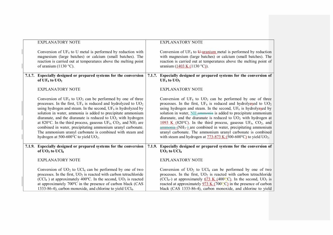
EXPLANATORY NOTE
Conversion of UF4 to U metal is performed by reduction with
magnesium (large batches) or calcium (small batches). The
reaction is carried out at temperatures above the melting point
of uranium (1130 °C).
EXPLANATORY NOTE
Conversion of UF4 to U uranium metal is performed by reduction
with magnesium (large batches) or calcium (small batches). The
reaction is carried out at temperatures above the melting point of
uranium (1403 K (1130 °C)).
7.1.7. Especially designed or prepared systems for the conversion
of UF6 to UO2
EXPLANATORY NOTE
Conversion of UF6 to UO2 can be performed by one of three processes. In the first, UF6 is reduced and hydrolyzed to UO2
using hydrogen and steam. In the second, UF6 is hydrolyzed by
solution in water, ammonia is added to precipitate ammonium
diuranate, and the diuranate is reduced to UO2 with hydrogen
at 820°C. In the third process, gaseous UF6, CO2, and NH3 are
combined in water, precipitating ammonium uranyl carbonate.
The ammonium uranyl carbonate is combined with steam and hydrogen at 500-600°C to yield UO2.
7.1.7. Especially designed or prepared systems for the conversion of
UF6 to UO2
EXPLANATORY NOTE
Conversion of UF6 to UO2 can be performed by one of three processes. In the first, UF6 is reduced and hydrolyzsed to UO2
using hydrogen and steam. In the second, UF6 is hydrolyzsed by
solution in water, NH3ammonia is added to precipitate ammonium
diuranate, and the diuranate is reduced to UO2 with hydrogen at
1093 K (820°C). In the third process, gaseous UF6, CO2, and
ammonia (NH3 ) are combined in water, precipitating ammonium
uranyl carbonate. The ammonium uranyl carbonate is combined with steam and hydrogen at 773-873 K (500-600°C) to yield UO2.
7.1.9. Especially designed or prepared systems for the conversion
of UO2 to UCl4
EXPLANATORY NOTE
Conversion of UO2 to UCl4 can be performed by one of two
processes. In the first, UO2 is reacted with carbon tetrachloride
(CCl4 ) at approximately 400ºC. In the second, UO2 is reacted
at approximately 700ºC in the presence of carbon black (CAS
1333-86-4), carbon monoxide, and chlorine to yield UCl4.
7.1.9. Especially designed or prepared systems for the conversion of
UO2 to UCl4
EXPLANATORY NOTE
Conversion of UO2 to UCl4 can be performed by one of two
processes. In the first, UO2 is reacted with carbon tetrachloride
(CCl4 ) at approximately 673 K (400º°C). In the second, UO2 is
reacted at approximately 973 K (700º°C) in the presence of carbon
black (CAS 1333-86-4), carbon monoxide, and chlorine to yield

UCl4.
7.2. Plants for the conversion of plutonium and equipment
especially designed or prepared therefor
INTRODUCTORY NOTE
Plutonium conversion plants and systems perform one or more
transformations from one plutonium chemical species to another, including: conversion of plutonium nitrate to PuO2,
conversion of PuO2 to PuF4, and conversion of PuF4 to
plutonium metal. Plutonium conversion plants are usually
associated with reprocessing facilities, but may also be associated with plutonium fuel fabrication facilities. Many of
the key equipment items for plutonium conversion plants are
common to several segments of the chemical process industry.
For example, the types of equipment employed in these
processes may include: furnaces, rotary kilns, fluidized bed
reactors, flame tower reactors, liquid centrifuges, distillation
columns and liquid-liquid extraction columns. Hot cells, glove boxes and remote manipulators may also be required.
However, few of the items are available “off-the-shelf”; most
would be prepared according to the requirements and
specifications of the customer. Particular care in designing for the special radiological, toxicity and criticality hazards
associated with plutonium is essential. In some instances,
special design and construction considerations are required to
address the corrosive properties of some of the chemicals
handled (e.g. HF). Finally, it should be noted that, for all
plutonium conversion processes, items of equipment which
individually are not especially designed or prepared for
plutonium conversion can be assembled into systems which are
7.2. Plants for the conversion of plutonium and equipment
especially designed or prepared therefor
INTRODUCTORY NOTE
Plutonium conversion plants and systems perform one or more
transformations from one plutonium chemical species to another, including: conversion of plutonium nitrate (PuN) to
plutonium(IV) dioxide (PuO2), , conversion of PuO2 to plutonium
tetrafluoride (PuF4PuF4), and conversion of PuF4 to plutonium
metal. Plutonium conversion plants are usually associated with reprocessing facilities, but may also be associated with plutonium
fuel fabrication facilities. Many of the key equipment items for
plutonium conversion plants are common to several segments of
the chemical process industry. For example, the types of
equipment employed in these processes may include: furnaces,
rotary kilns, fluidizsed bed reactors, flame tower reactors, liquid
centrifuges, distillation columns and liquid-liquid extraction columns. Hot cells, glove boxes and remote manipulators may also
be required. However, few of the items are available “‘off-the-
shelf’”; most would be prepared according to the requirements and
specifications of the customer. Particular care in designing for the special radiological, toxicity and criticality hazards associated with
plutonium is essential. In some instances, special design and
construction considerations are required to address the corrosive
properties of some of the chemicals handled (e.g. e.g., hydrogen
fluoride (HF)). Finally, it should be noted that, for all plutonium
conversion processes, items of equipment which individually are
not especially designed or prepared for plutonium conversion can
be assembled into systems which are especially designed or
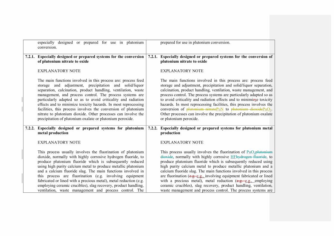
especially designed or prepared for use in plutonium
conversion.
prepared for use in plutonium conversion.
7.2.1. Especially designed or prepared systems for the conversion
of plutonium nitrate to oxide
EXPLANATORY NOTE
The main functions involved in this process are: process feed
storage and adjustment, precipitation and solid/liquor
separation, calcination, product handling, ventilation, waste
management, and process control. The process systems are
particularly adapted so as to avoid criticality and radiation
effects and to minimize toxicity hazards. In most reprocessing facilities, this process involves the conversion of plutonium
nitrate to plutonium dioxide. Other processes can involve the
precipitation of plutonium oxalate or plutonium peroxide.
7.2.1. Especially designed or prepared systems for the conversion of
plutonium nitrate to oxide
EXPLANATORY NOTE
The main functions involved in this process are: process feed
storage and adjustment, precipitation and solid/liquor separation,
calcination, product handling, ventilation, waste management, and
process control. The process systems are particularly adapted so as
to avoid criticality and radiation effects and to minimizse toxicity
hazards. In most reprocessing facilities, this process involves the conversion of plutonium nitratePuN to plutonium dioxidePuO2.
Other processes can involve the precipitation of plutonium oxalate
or plutonium peroxide.
7.2.2. Especially designed or prepared systems for plutonium
metal production
EXPLANATORY NOTE
This process usually involves the fluorination of plutonium
dioxide, normally with highly corrosive hydrogen fluoride, to
produce plutonium fluoride which is subsequently reduced
using high purity calcium metal to produce metallic plutonium
and a calcium fluoride slag. The main functions involved in
this process are fluorination (e.g. involving equipment
fabricated or lined with a precious metal), metal reduction (e.g.
employing ceramic crucibles), slag recovery, product handling,
ventilation, waste management and process control. The
7.2.2. Especially designed or prepared systems for plutonium metal
production
EXPLANATORY NOTE
This process usually involves the fluorination of PuO2plutonium
dioxide, normally with highly corrosive HFhydrogen fluoride, to
produce plutonium fluoride which is subsequently reduced using
high purity calcium metal to produce metallic plutonium and a
calcium fluoride slag. The main functions involved in this process
are fluorination (e.g. e.g., involving equipment fabricated or lined
with a precious metal), metal reduction (e.g. e.g., employing
ceramic crucibles), slag recovery, product handling, ventilation,
waste management and process control. The process systems are
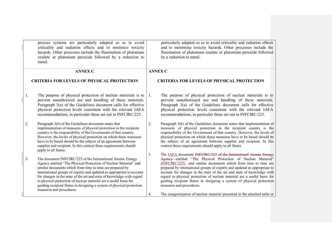
process systems are particularly adapted so as to avoid
criticality and radiation effects and to minimize toxicity
hazards. Other processes include the fluorination of plutonium
oxalate or plutonium peroxide followed by a reduction to
metal.
particularly adapted so as to avoid criticality and radiation effects
and to minimizse toxicity hazards. Other processes include the
fluorination of plutonium oxalate or plutonium peroxide followed
by a reduction to metal.
ANNEX C
CRITERIA FOR LEVELS OF PHYSICAL PROTECTION
1. The purpose of physical protection of nuclear materials is to
prevent unauthorized use and handling of these materials.
Paragraph 3(a) of the Guidelines document calls for effective physical protection levels consistent with the relevant IAEA
recommendations, in particular those set out in INFCIRC/225.
2. Paragraph 3(b) of the Guidelines document states that
implementation of measures of physical protection in the recipient
country is the responsibility of the Government of that country.
However, the levels of physical protection on which these measures
have to be based should be the subject of an agreement between
supplier and recipient. In this context these requirements should
apply to all States.
3. The document INFCIRC/225 of the International Atomic Energy
Agency entitled “The Physical Protection of Nuclear Material” and
similar documents which from time to time are prepared by
international groups of experts and updated as appropriate to account for changes in the state of the art and state of knowledge with regard
to physical protection of nuclear material are a useful basis for
guiding recipient States in designing a system of physical protection measures and procedures.
ANNEX C
CRITERIA FOR LEVELS OF PHYSICAL PROTECTION
1. The purpose of physical protection of nuclear materials is to
prevent unauthorizsed use and handling of these materials.
Paragraph 3(a) of the Guidelines document calls for effective physical protection levels consistent with the relevant IAEA
recommendations, in particular those set out in INFCIRC/225.
2. Paragraph 3(b) of the Guidelines document states that implementation of
measures of physical protection in the recipient country is the
responsibility of the Government of that country. However, the levels of
physical protection on which these measures have to be based should be
the subject of an agreement between supplier and recipient. In this
context these requirements should apply to all States.
3. The IAEA document INFCIRC/225 of the International Atomic Energy
Agency entitled “The Physical Protection of Nuclear Material”
(INFCIRC/225) and similar documents which from time to time are
prepared by international groups of experts and updated as appropriate to
account for changes in the state of the art and state of knowledge with regard to physical protection of nuclear material are a useful basis for
guiding recipient States in designing a system of physical protection
measures and procedures.
4. The categorizsation of nuclear material presented in the attached table or

4. The categorization of nuclear material presented in the attached table
or as it may be updated from time to time by mutual agreement of suppliers shall serve as the agreed basis for designating specific
levels of physical protection in relation to the type of materials, and
equipment and facilities containing these materials, pursuant to
paragraph 3(a) and 3(b) of the Guidelines document.
as it may be updated from time to time by mutual agreement of suppliers
shall serve as the agreed basis for designating specific levels of physical protection in relation to the type of materials, and equipment and
facilities containing these materials, pursuant to paragraph 3(a) and 3(b)
of the Guidelines document.
CATEGORY I
Materials in this category shall be protected with highly reliable systems against unauthorized use as follows:
Use and storage within a highly protected area, i.e., a protected area
as defined for Category II above, to which, in addition, access is
restricted to person whose trustworthiness has been determined, and which is under surveillance by guards who are in close
communication with appropriate response forces. Specific measures
taken in this context should have as their objective the detection and prevention of any assault, unauthorized access or unauthorized
removal of material.
Transportation under special precautions as identified above for transportation of Category II and III materials and, in addition, under
constant surveillance by escorts and under conditions which assure
close communication with appropriate response forces.
6. Suppliers should request identification by recipients of those agencies
or authorities having responsibility for ensuring that levels of protection are adequately met and having responsibility for internally
co-ordinating response/recovery operations in the event of
unauthorized use or handling of protected materials. Suppliers and
recipients should also designate points of contact within their national
authorities to co-operate on matters of out-of-country transportation
and other matters of mutual concern.
CATEGORY I
Materials in this category shall be protected with highly reliable systems against unauthorizsed use as follows:
Use and storage within a highly protected area, (i.e., a protected area as
defined for Category II above), to which, in addition, access is restricted
to persons whose trustworthiness has been determined, and which is under surveillance by guards who are in close communication with
appropriate response forces. Specific measures taken in this context
should have as their objective the detection and prevention of any assault, unauthorizsed access or unauthorizsed removal of material.
Transportation under special precautions as identified above for
transportation of Category II and III materials and, in addition, under constant surveillance by escorts and under conditions which assure close
communication with appropriate response forces.
6. Suppliers should request identification by recipients of those agencies or
authorities having responsibility for ensuring that levels of protection are
adequately met and having responsibility for internally co-ordinating response/recovery operations in the event of unauthorizsed use or
handling of protected materials. Suppliers and recipients should also
designate points of contact within their national authorities to co-operate
on matters of out-of-country transportation and other matters of mutual
concern.
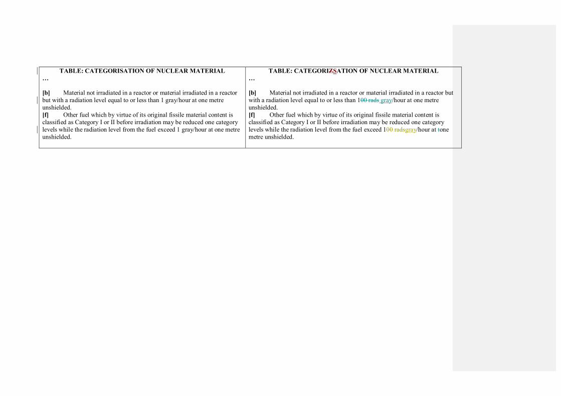
TABLE: CATEGORISATION OF NUCLEAR MATERIAL
…
[b] Material not irradiated in a reactor or material irradiated in a reactor
but with a radiation level equal to or less than 1 gray/hour at one metre
unshielded.
[f] Other fuel which by virtue of its original fissile material content is
classified as Category I or II before irradiation may be reduced one category
levels while the radiation level from the fuel exceed 1 gray/hour at one metre
unshielded.
TABLE: CATEGORIZSATION OF NUCLEAR MATERIAL
…
[b] Material not irradiated in a reactor or material irradiated in a reactor but
with a radiation level equal to or less than 100 rads gray/hour at one metre
unshielded.
[f] Other fuel which by virtue of its original fissile material content is
classified as Category I or II before irradiation may be reduced one category
levels while the radiation level from the fuel exceed 100 radsgray/hour at tone
metre unshielded.