Inertia Switch R - TOPIxtopix.jaguar.jlrext.com/topix/service/archive/62698/roadside... · Jaguar...
26
157 Inertia Switch Roadside Emergency RESETTING THE INERTIA SWITCH In the event of an accident, an inertia switch will trip, isolating the fuel supply. Once the switch has tripped it must be reset before attempting to restart the engine. The inertia switch is located in the footwell behind the trim on the right-hand side of the vehicle, forward of the front door post, below the fascia. A finger access hole allows the driver to reset the switch. ! WARNING: To avoid the possibility of fire or personal injury, do not reset the inertia switch if you see or smell fuel. If no fuel leak is apparent, reset the inertia switch as follows: 1. Turn the ignition switch to position 0. 2. Press down the flexible cover on the top of the inertia switch. 3. Turn the ignition switch to position II, pause for a few seconds, then return the key to position 0. 4. Make a further check for fuel leaks.
Transcript of Inertia Switch R - TOPIxtopix.jaguar.jlrext.com/topix/service/archive/62698/roadside... · Jaguar...

Inertia Switch
R
Roadside Emergency
RESETTING THE INERTIA SWITCH
In the event of an accident, an inertia switch will trip, isolating the fuel supply. Once the switch has tripped it must be reset before attempting to restart the engine.
The inertia switch is located in the footwell behind the trim on the right-hand side of the vehicle, forward of the front door post, below the fascia. A finger access hole allows the driver to reset the switch.
! WARNING:To avoid the possibility of fire or personal injury, do not reset the inertia switch if you see or smell fuel.
If no fuel leak is apparent, reset the inertia switch as follows:
1. Turn the ignition switch to position 0.
2. Press down the flexible cover on the top of the inertia switch.
3. Turn the ignition switch to position II, pause for a few seconds, then return the key to position 0.
4. Make a further check for fuel leaks.
157

Emergency Starting
L
Emergency Starting
ROLLING START(Manual transmission only)
! WARNING:• It will not be possible to push or tow
start a vehicle with automatic transmission.
• Only jump lead starting or the fitting of a fully charged battery is recommended.
• Because of the dangers to other road users, extreme caution must be exercised when attempting a rolling start.
A rolling start is pushing or towing the vehicle at low speed, in gear (preferably 2nd) with the clutch pedal depressed and the ignition switch in position II.
When sufficient forward speed is obtained, the clutch pedal is gently released and the traction force from the wheels starts the engine.
It may be difficult to start a cold diesel engine by pushing or towing the vehicle, as the cold starting system cannot be activated if the battery is flat.
JUMP LEADSBoth the booster and discharged battery should be treated with great care when using jump leads. Always use high quality leads capable of carrying the starter current of the vehicle to be started.
Before commencing, the following precautions must be taken:
• When the battery of another vehicle is being used, ensure that the vehicles do not touch. Alternatively, remove the charged battery and place near to, not on, the vehicle with the discharged battery.
• Ensure that both vehicles have all electrical services OFF, the handbrake is ON and, with automatic transmission, P is selected.
• Where the jump leads are of a different colour, e.g. red and black, use red for positive (+). This aids identification and helps to avoid crossing positive (+) to negative (-). Take extra care to avoid crossing the polarity when using cables of the same colour.
Caution:
• If using a jump start vehicle, under no circumstances should the vehicles come into contact with each other. This could establish an earth connection, which may cause sparks and damage.
• Do not run the jump start vehicle’s engine when boost starting a Jaguar vehicle. If the jump start vehicle’s engine is running and the jump leads are disconnected, damage to the Jaguar vehicle’s electrical system will result.
• The booster battery voltage must not exceed 12 volts.
158
Emergency Starting
R
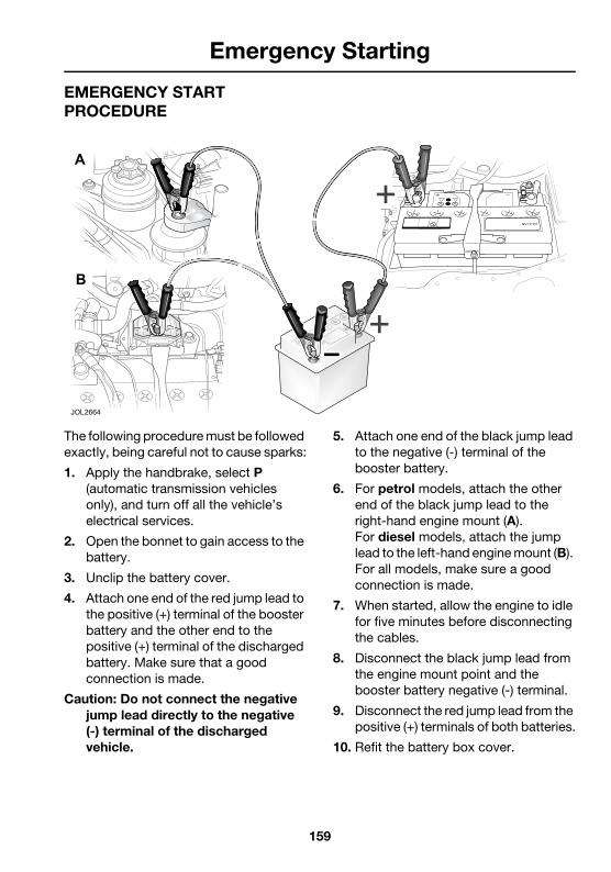
EMERGENCY START PROCEDURE
The following procedure must be followed exactly, being careful not to cause sparks:
1. Apply the handbrake, select P (automatic transmission vehicles only), and turn off all the vehicle’s electrical services.
2. Open the bonnet to gain access to the battery.
3. Unclip the battery cover.
4. Attach one end of the red jump lead to the positive (+) terminal of the booster battery and the other end to the positive (+) terminal of the discharged battery. Make sure that a good connection is made.
Caution: Do not connect the negative jump lead directly to the negative (-) terminal of the discharged vehicle.
5. Attach one end of the black jump lead to the negative (-) terminal of the booster battery.
6. For petrol models, attach the other end of the black jump lead to the right-hand engine mount (A). For diesel models, attach the jump lead to the left-hand engine mount (B). For all models, make sure a good connection is made.
7. When started, allow the engine to idle for five minutes before disconnecting the cables.
8. Disconnect the black jump lead from the engine mount point and the booster battery negative (-) terminal.
9. Disconnect the red jump lead from the positive (+) terminals of both batteries.
10. Refit the battery box cover.
159

Wheel Changing
L
Wheel Changing
Spare Wheel Location
Be prepared for a flat tyre. Know where equipment is stowed and read the wheel changing and jacking instructions carefully.
Pull off the road completely, clear of all traffic and park on as level, solid ground as possible. Switch on hazard warning lights and, where legally required, display the warning triangle.
! WARNING:• It can be dangerous to change a
wheel when the vehicle is on a slope or soft, uneven ground.
• Wheels are extremely heavy. Take care when lifting and particularly when removing and replacing a wheel in its storage position in the luggage compartment.
The spare wheel and jacking equipment are stored under the luggage compartment floor panel.
To remove the spare wheel, lift the luggage compartment floor panel. If a temporary-use spare wheel is stowed then the tray will need to be removed to gain access to the wheel.Unscrew the retaining nut (1) and remove the spare wheel. Remove the jack and wheel nut wrench (and locking wheel nut kit).
Estate: The floor panel of Estate models is fitted with a retaining strap (2), which can be hooked over the top lip of the luggage compartment opening. This holds the floor panel out of the way, to make access to the spare wheel easier. Remove the stowage tray (3) to access the spare wheel.
160

Wheel Changing
R
Temporary-use Spare WheelObserve the following warnings before using the wheel.
! WARNING:• Please note temporary-use spare
wheel warning label. Adhere to instructions on the label. Failure to comply can be dangerous.
• When a temporary-use spare wheel is fitted, drive with caution and replace with the specified wheel and tyre as soon as possible.
• Do not fit more than one temporary-use spare wheel and tyre assembly at one time.
• The temporary-use spare wheel must be inflated to the correct pressure. Refer to the tyre recommendation label on the end of the dashboard on the driver’s side of the vehicle.
• Temporary-use spare wheel, maximum speed is 80 km/h (50 mph).
Note: Maintenance information for the temporary-use spare wheel is the same as given for normal tyres.
Locking Wheel Nuts
Where Jaguar locking wheel nuts are fitted (one on each wheel), they can only be removed using the correct key socket.
The locking wheel nut comprises two grooved parts, front and rear, which must be turned together to allow the nut to be fitted or removed.
To remove the nut, the front and rear grooves must be aligned. Locate the key socket in the grooves and push it fully over both parts of the nut. Fit the wheel nut wrench over the key socket and loosen the locking wheel nut.
Attempting to remove the nut without the correct key socket (such as attempted theft) or with the socket not located over the rear part of the nut, will cause the front part only (1) to turn.
161

Wheel Changing
L
If this has happened, rotate the front part with the key socket until the grooves are re-aligned and then push the socket fully over the nut.
Should a new key socket be required, contact your Jaguar Dealer/Authorised Repairer. Proof of vehicle ownership will be required.
Wheel Changing1. Ensure that all passengers are in a
safe place, clear of the vehicle.
2. Firmly apply the handbrake.
3. For automatic vehicles, select gear position P (Park).
4. For vehicles with manual transmission, select a low gear.
5. Ensure that the jack is placed on firm and level ground.
! WARNING:Before attempting to lift the vehicle with the jack, block a wheel diagonally opposite to the wheel being replaced to prevent the vehicle from rolling when jacked up.
Before raising the vehicle, extend the telescopic wheel nut wrench and slacken, but do not remove the wheel nuts.
! WARNING:Never work under the vehicle using only the jack as a support, always use axle stands or suitable supports under the jacking points.
Observe the instructions printed on the jack.
Use the jack only for lifting the vehicle during wheel changing, and only use the jack which is stored in the vehicle.
Do not start or run the engine while the vehicle is only supported by a jack.
Note: When one rear wheel is lifted off the ground the selection of a low gear on manual vehicles or automatic transmission P (Park) position will not prevent the vehicle from moving and possibly slipping off the jack.
Caution: Ensure that when anyone requires to raise the vehicle that the jack is correctly positioned to avoid any damage to the vehicle sills or sill panels. Use only the correct jacking points; never use suspension components, bumpers or any other part of the body to lift the vehicle.
162

Wheel Changing
R
There are four jacking points, two each side of the vehicle on the underside of the floor. These provide positive location for the jack.
Two indented, triangular jack location points are provided on each sill cover.
The simplest way to correctly locate the jacking point is to feel along the sill panel to the triangular indentation and then fit the jack head to the body flange as shown in the illustration above.
! WARNING:• Do not attempt to lift the vehicle
unless the jack head is fully engaged in the jacking point.
• Ensure that the handbrake is fully applied.
Place the jack squarely beneath the appropriate jacking point. Ensure that the jack head is fully engaged. Carefully raise the vehicle by turning the handle. Stop jacking the vehicle when the tyre just clears the ground. Minimum tyre lift gives maximum vehicle stability.
Remove the wheel nuts and the wheel.
When changing the alloy road wheels, transfer the centre badge to the replacement wheel (when a full size spare wheel is used). Using the rounded end of the wheel nut wrench handle from the inside of the wheel, push the centre badge from its housing. Push the centre badge into the replacement wheel. If the temporary-use spare wheel is to be fitted, keep the centre badge safely and fit it to the repaired full size wheel when it has been refitted.
! WARNING:When the temporary-use spare wheel has been fitted, drive with caution and replace with the specified wheel and tyre as soon as possible.
Fitting the spare wheel
Fit the spare wheel and loosely secure with the wheel nuts.
Using the wheel nut wrench, lightly tighten the wheel nuts alternately using the sequence shown in the illustration.
Lower the jack and tighten the wheel nuts alternately, DO NOT OVERTIGHTEN.
At the earliest opportunity have the wheel nuts tightened with a torque wrench to:
Alloy wheels:
• 103 Nm ± 15.5 (75.95 lbf.ft. ± 11.4).
Steel wheels:
• 80 Nm ± 12.0 (59.0 lbf.ft. ± 8.5).
These torque figures must not be exceeded.
163

Wheel Changing
L
Stowing the equipmentStow the jack and wrench.
Stow the replaced road wheel in the luggage compartment, position the wheel and secure with the retaining nut. Reposition the luggage compartment floor panel.
Note: Examine the jack occasionally and clean and grease the threads to ensure it is always ready for an emergency.
164

Vehicle Recovery
R
Vehicle Recovery
RECOMMENDED METHODSCaution:
• The preferred and recommended vehicle recovery method is by using a flat bed transporter.
• Ensure that the recovery team do not tow with sling-type equipment since damage to the bodywork may result.
The removable towing eye is primarily for emergency use when towing for SHORT DISTANCES, e.g. removing the vehicle if it is causing an obstruction or for winching the vehicle onto a recovery transporter.
! WARNING:When the engine is not running the steering and brakes will no longer be power assisted.
Therefore, be prepared for relatively heavy steering and the need for greatly increased brake pedal pressure.
VEHICLE FAILUREFor towing and recovery purposes, note that the model range includes both front wheel drive (FWD) and all-wheel drive (AWD) vehicles.
Always obey towing regulations. In certain countries the registration number of the towing vehicle and an ON TOW sign or warning triangle must be displayed in a prominent position at the rear of the vehicle being towed.
When being towed, the vehicle’s gear selector lever must be in neutral (position N) with the ignition key turned to position II to release the steering lock and render the indicators, horn and brake lights operational.
All-wheel drive vehicles
Caution:
• Do not tow an all-wheel drive (AWD) vehicle with the front wheels lifted unless the propshaft to the rear wheels is disconnected at the final drive flange. If the propshaft is not disconnected, the rotating rear wheels will force the front wheels to rotate, even with the gear selector in neutral.
• The vehicle can be towed with all four wheels on the ground, provided there is no damage to the transmission, for a maximum distance of 50 kilometres (30 miles) with the speed not exceeding 50 km/h (30 mph).
Automatic transmissionTo prevent damage to the automatic transmission whilst an AWD vehicle is being towed with the rear wheels on the ground, towing distance must be restricted to 0.8 kilometres (0.5 miles). Towing speed must not exceed 50 km/h (30 mph).
165

Vehicle Recovery
L
TRANSPORTING
When the vehicle is being transported on a trailer or vehicle flat bed transporter, the handbrake must be applied, the wheels chocked and:
• The automatic gear selector lever moved to position N or D but NEVER to P.
• The manual gear selector lever moved to the neutral position.
The vehicle must be securely tied down to the transporter or trailer. There are four transporter tie-down brackets on the vehicle underbody. Do not attach tie-down hooks to the towing eye.
Suspended towingEnsure that the recovery team do not tow with sling-type equipment since damage to the bodywork may result.
Caution: Do not tow an all-wheel drive (AWD) vehicle with the front wheels lifted unless the propshaft to the rear wheels is disconnected at the final drive flange. If the propshaft is not disconnected, the rotating rear wheels will force the front wheels to rotate, even with the gear selector in neutral.
TOWING EYESA screw-in towing eye is provided in the luggage compartment with the jack and can be fitted to the front or rear of the vehicle.
Note: The towing eye has a left-hand thread and must be turned in an anti-clockwise direction when fitting.
Caution:
• The towing eye is not suitable for solid bar towing.
• Care must be taken to avoid damaging the bumpers.
166

Vehicle Recovery
R
Front tow point
The front towing point is located behind a square cover on the face of the bumper on the left-hand side of the vehicle. To access the towing point, push the top of the tow point cover inwards and upwards, which will cause the cover to pop out of place. Lift the cover from the access hole. The tow point cover is attached to the vehicle by a retaining strap.
Screw the towing eye into the vehicle, right up to the shoulder.
After removal of the towing eye, insert the top edge of the tow point cover into the access hole, and press the bottom edge of the cover into place.
Rear tow point
! WARNING:Avoid body contact with a hot exhaust pipe when fitting the eye to the rear towing point.
The rear towing point is alongside the left-hand exhaust pipe.
Remove the small cover from the bumper. Remove the bung and screw the towing eye into the vehicle, right up to the shoulder.
Estate vehicles with Sports body kitEstate vehicles that are fitted with the optional Sports Collection body kit, need the extension bar (provided with the kit) to be fitted, to avoid any contact with the new rear valance.
167

Bulb Renewal
L
Bulb Renewal
OVERVIEWIt is important that only Jaguar bulbs of the type specified are used when renewing bulbs.
Before renewing bulbs, switch off the ignition and light switches.
Caution: Halogen type bulbs will be damaged if touched by hand or contaminated with oil or grease. It is important to use clean gloves or cloth when handling a bulb which is to be used again. A contaminated bulb may be cleaned with methylated spirit before refitting.
MAIN BEAM (INNER) HEADLIGHTOpen the bonnet.
For access to the left-hand side bulb, remove the battery.
Turn the circular cover (1) anti-clockwise and remove.
Press the spring clip (2) towards the bulb and downwards to release the bulb. Remove the bulb/connector (3) from the headlight assembly. Pull the connector from the bulb.
Attach the connector to the new bulb, type H1 Super for main beam, and fit to the headlight. The bulb will only correctly fit in one position.
Engage the spring clips to retain the bulb and then fit the circular cover.
Refit the top cover and close the bonnet.
It is advisable to have the headlight aim checked by a Dealer/Authorised Repairer after bulb renewal.
168

Bulb Renewal
R
DIP BEAM (OUTER) HEADLIGHT
Open the bonnet.
For access to the left-hand side bulb, remove the battery and battery box.
Slide open the two spring clips (1) and remove the cover (2).
Press the spring clip (3) inwards and push towards the bulb (4) to release the bulb and then remove the bulb from the light unit. Pull the connector (5) from the bulb.
Fit a new bulb to the connector, type H1 for dipped beam.
Fit the bulb to the light unit, the bulb will only correctly fit in one position. Engage the spring clips to retain the bulb and then fit the cover and retain using the two spring clips.
Close the bonnet.
Note: High Intensity Discharge (HID) Xenon light units, type D2S 35W, are not renewable, contact your Dealer/ Authorised Repairer if the headlight fails to operate.
SIDE REPEATER IINDICATOR
Remove the light unit by pushing the lens towards the front of the vehicle to compress the spring clip and then pull the rear outwards to remove the complete unit.
Twist the bulb holder anti-clockwise and pull it from the lens. Pull the capless bulb from the holder and fit a new one of the correct type, WY5W. Fit the bulb holder to the lens.
169

Bulb Renewal
L
Place the inner rear of the lens unit into the recess and then push the front of the lens inwards until it clicks into place.
FRONT PARKING (SIDE) LIGHT
Open the bonnet.
The front parking lights are contained within the inner headlight units.
For access to the left-hand side bulb, remove the battery and the battery box.
Turn the circular cover anti-clockwise and remove.
Pull the small bulb holder from the headlight unit.
Pull the capless bulb from the holder and fit a new one of the correct type, W5W.
Push the bulb holder into the headlight unit.
Fit the circular cover.
Close the bonnet.
FRONT DIRECTION INDICATOR
Open the bonnet.
The bulb is contained within the outer headlight.
Slide open the two spring clips and remove the cover.
Turn the holder a quarter turn anti-clockwise and remove the bulb and holder.
Remove the bulb and fit a new one of the correct type, PY21W.
Fit the holder to the light unit, it will only fit in one position.
Fit the cover and retain using the two spring clips.
Close the bonnet.
170

Bulb Renewal
R
NUMBER PLATE LIGHT
Push the lens clip sideways and remove the lens from the vehicle.
Remove the bulb and fit a new one of the correct type, W5W.
Refit the lens by pressing it firmly into the recess until it clicks into place.
FRONT FOG LIGHTIt is recommended that the front fog light bulb is renewed by a Jaguar Dealer/ Authorised Repairer.
REAR LIGHT ASSEMBLY - SALOON
The rear light assembly has the following bulbs:
1. Reverse light, type P21W.
2. Stop/tail light, type P21/5W.
3. Fog light, type P21W.
4. Tail light, type P21/5W.
5. Direction indicator, type PY21W.
Ensure that the lights and ignition switch are OFF before removing any bulbs.
Open the luggage compartment, loosen the side carpet and unclip the rear light bulb carrier.
171
Bulb Renewal
L
Remove the faulty bulb and fit a new one of the correct type, as illustrated on the bulb holder. Fitment of the correct type is essential.
Refit the bulb carrier assembly, ensuring that the clips are correctly secured.
Refit the carpet.
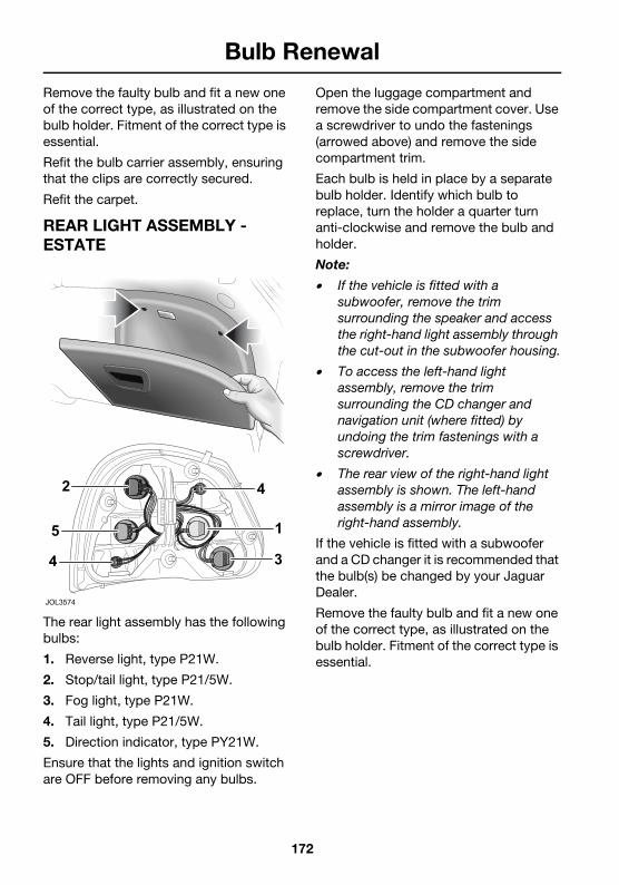
REAR LIGHT ASSEMBLY - ESTATE
The rear light assembly has the following bulbs:
1. Reverse light, type P21W.
2. Stop/tail light, type P21/5W.
3. Fog light, type P21W.
4. Tail light, type P21/5W.
5. Direction indicator, type PY21W.
Ensure that the lights and ignition switch are OFF before removing any bulbs.
Open the luggage compartment and remove the side compartment cover. Use a screwdriver to undo the fastenings (arrowed above) and remove the side compartment trim.
Each bulb is held in place by a separate bulb holder. Identify which bulb to replace, turn the holder a quarter turn anti-clockwise and remove the bulb and holder.
Note:
• If the vehicle is fitted with a subwoofer, remove the trim surrounding the speaker and access the right-hand light assembly through the cut-out in the subwoofer housing.
• To access the left-hand light assembly, remove the trim surrounding the CD changer and navigation unit (where fitted) by undoing the trim fastenings with a screwdriver.
• The rear view of the right-hand light assembly is shown. The left-hand assembly is a mirror image of the right-hand assembly.
If the vehicle is fitted with a subwoofer and a CD changer it is recommended that the bulb(s) be changed by your Jaguar Dealer.
Remove the faulty bulb and fit a new one of the correct type, as illustrated on the bulb holder. Fitment of the correct type is essential.
172

Bulb Renewal
R
HIGH MOUNTED STOP LIGHTThe high mounted stop light is an LED type. Should one or more LEDs fail then the unit may cease to meet legal requirements and must be renewed immediately by a Jaguar Dealer/ Authorised Repairer.
173
Fuses
L
Fuses
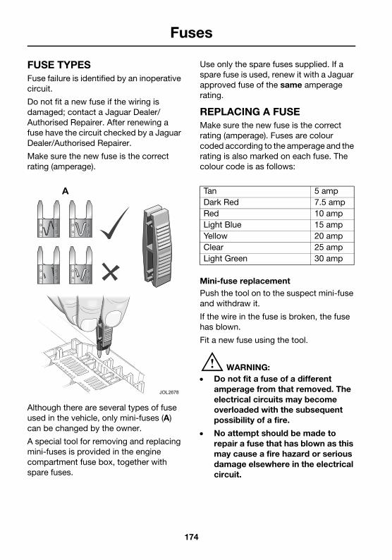
FUSE TYPESFuse failure is identified by an inoperative circuit.
Do not fit a new fuse if the wiring is damaged; contact a Jaguar Dealer/ Authorised Repairer. After renewing a fuse have the circuit checked by a Jaguar Dealer/Authorised Repairer.
Make sure the new fuse is the correct rating (amperage).
Although there are several types of fuse used in the vehicle, only mini-fuses (A) can be changed by the owner.
A special tool for removing and replacing mini-fuses is provided in the engine compartment fuse box, together with spare fuses.
Use only the spare fuses supplied. If a spare fuse is used, renew it with a Jaguar approved fuse of the same amperage rating.
REPLACING A FUSEMake sure the new fuse is the correct rating (amperage). Fuses are colour coded according to the amperage and the rating is also marked on each fuse. The colour code is as follows:
Mini-fuse replacementPush the tool on to the suspect mini-fuse and withdraw it.
If the wire in the fuse is broken, the fuse has blown.
Fit a new fuse using the tool.
! WARNING:• Do not fit a fuse of a different
amperage from that removed. The electrical circuits may become overloaded with the subsequent possibility of a fire.
• No attempt should be made to repair a fuse that has blown as this may cause a fire hazard or serious damage elsewhere in the electrical circuit.
Tan 5 ampDark Red 7.5 ampRed 10 ampLight Blue 15 ampYellow 20 ampClear 25 ampLight Green 30 amp
174

Fuses
R
FUSE BOX LOCATIONSThere are two fuse boxes fitted to the vehicle, each one containing fuses protecting a different group of circuits.
They are located in:
1. The engine compartment.
2. The passenger compartment.
Caution: When a fuse box lid is removed, take care to protect the box from moisture, and refit the lid at the earliest opportunity.
Engine compartment fuse box
The fuse box is located in the engine compartment on the left-hand side adjacent to the battery.
Remove the fuse box lid by pressing the retaining lug at the front of the lid and lifting the lid clear of the rear hinges.
A tool for removing the mini-fuses is located in the fuse box.
When refitting, relocate the fuse box lid in the hinges at the rear of the fuse box and press the retaining lug at the front of the lid into place.
175

Fuses
L
Passenger compartment fuse box
To locate the fuse box, open the glove compartment and pull out the panel (1). The fuse box is visible through the aperture.
A tool for removing the mini-fuses is located in the engine compartment fuse box.
A torch or flashlight may be required to properly identify the fuses.
176

Fuses
R
FUSE POSITIONS
1. Engine compartment fuse box.
2. Passenger compartment fuse box.
JOL2956
177

Fuses
L
ENGINE COMPARTMENT FUSES (1)
Fuse No Rating (amps) CircuitF1 10 Right-hand main beam.F2 15 Front fog lights, master light switch.F3 20 Horns (diesel only).F4 10 Left-hand main beam.F5 10 Air conditioning compressor clutch.F6 7.5 Alternator (petrol only).F7 5 Fuel-fired heater relay coil (diesel only).F8 30 Wiper switch.F9 30 Wiper switch, windscreen washer pump, wiper motor.
F10 15 Ignition coils (petrol only).F11 15 Automatic transmission control module.F12 7.5 Supplementary heater relay coil (diesel only).F13 5 Traction control system, anti-lock braking system,
dynamic stability control system.F14 30 Heated front screen left-hand side.F15 30 Heated front screen right-hand side.F16 5 Radiator fans speed control.F17 10 Fuel injectors (petrol only).
Exhaust gas recirculation, variable geometry turbocharger control (diesel only).
F18 10 Canister purge valve, airflow meter, inlet manifold tuning valve, canister close valve, vacuum module (petrol only).Cruise control module (2.0L petrol only).Glowplug relay coil (diesel only).
F19 10 Engine control module (petrol only).Throttle motor relay (2.5L and 3.0L).Fuel pump relay (2.0L petrol).
F20 30 (petrol)
7.5 (diesel)
Oxygen sensor heaters B (petrol only).Inlet manifold valve (diesel only).
F21 30 (petrol)
15 (diesel)
Oxygen sensor heaters A (petrol only).Airflow meter, engine control module (diesel only).
F22 60 Glow plugs (diesel only. This fuse should only be replaced by a Jaguar Dealer/Authorised Repairer).
F23 Not used.F24 30 Power wash pump.F25 Not used.
178

Fuses
R
F26 Not used.F27 15 Transit relay, vacuum module, battery backed sounder.F28 Not used.F29 See adjacent
textLeft-hand dip beam, master light switch (autolights), head light levelling, instrument cluster.
Note: This fuse is rated at 20 A for diesel models that ARE fitted with HID headlights, and for ALL petrol models. For diesel models that are NOT fitted with HID headlights, a 10 A fuse is required.
F30 See adjacent text
Right-hand dipped beam.
Note: This fuse is rated at 20 A for diesel models that ARE fitted with HID headlights, and for ALL petrol models. For diesel models that are NOT fitted with HID headlights, a 10 A fuse is required.
F31 15 Fuel-fired heater (diesel only).F32 15 Automatic transmission control module.F33 Not used.F34 30 Starter motor solenoid.F35 5 Ignition relay coil.F36 5 (petrol)
7.5 (diesel)
Engine control module.Battery sense to alternator (diesel only).
F37 Not used.F38 20 (petrol)
30 (diesel)
Horns (petrol only).Auxiliary heater (diesel only).
Fuse No Rating (amps) Circuit
179

Fuses
L
PASSENGER COMPARTMENT FUSES (2)
Fuse No Rating (amps) CircuitF1 Not used.F2 10 Instrument panel, electrochromic mirror, reverse light
switch, reverse lights.F3 30 Passenger seat adjustment motors.F4 20 Accessory connectors.F5 20 Rear wiper (Estate only).F6 Not used.F7 10 On board diagnostics, heated front seat modules, rain
sensing system, JaguarVoice.F8 20 Heated front seat modules.F9 10 Driver’s seat memory function.
F10 15 Sunroof module, SRX antenna.F11 20 Left-hand (front and rear) electric window motors.F12 10 VICS (Japan), JaguarVoice.F13 Not used.F14 30 Heated rear screen.F15 10 Heated door mirrors.F16 30 Driver’s seat adjustment motors.F17 20 Fuel pump driver module and relay.F18 15 Rear accessory socket (Estate only).F19 30 Tow-bar module.
Rear accessory socket (Estate only).F20 30 Premium ICE amplifier unit.F21 20 Right-hand (front and rear) electric window motors.F22 15 Door lock module.F23 20 Rear screenwash pump (Estate only).F24 20 Screenwash pump.F25 5 On board diagnostics.F26 10 Manual transmission cruise control clutch switch, rotary
switch.F27 5 Touch-screen.F28 15 Front and rear accessory sockets.F29 7.5 Rear fog lights.F30 5 In-car telephone, PSE.F31 15 Ignition switch.F32 5 On board diagnostics.
180

Fuses
R
F33 5 Park aid.F34 10 Reverse switch.F35 15 Direction power module.F36 20 Throttle motor relay (2.5L and 3.0L).
Fuel pump (2.0L petrol only).F37 30 Climate control blower motor.F38 15 Exterior light switch.F39 10 HID module, air conditioning ECU, blower motor relay
coil.F40 5 Sunroof module, electrochromic mirror, power window
motors and switches.F41 5 Passenger airbag light, passenger seat weight sensor.F42 5 Power steering module.F43 10 Instrument panel, telematics display, ICE head unit,
antenna module, VICS (Japan), navigation system, park aid, JaguarVoice, In-car telephone, accessory relay coil.
F44 15 Navigation system ECU, CD player, ICE head unit.F45 10 Air conditioning ECU.F46 7.5 Power fold back door mirrors.F47 7.5 Left-hand side (parking) lights.F48 7.5 Right-hand side (parking) lights.F49 10 Air conditioning ECU, interior courtesy lights, roof
console, in-car sensor.F50 5 Automatic transmission control module.F51 7.5 Manual transmission cruise control clutch switch, brake
switch.F52 15 Cigar lighter.F53 10 Airbag module ignition supply.F54 5 Instrument panel ignition supply.F55 5 Number plate lights, glove compartment light,
Instrument panel.F56 Not used.
Fuse No Rating (amps) Circuit
181

Fire Extinguisher
L
Fire Extinguisher
DEALER FITTED FIRE EXTINGUISHERMany countries make it compulsory to carry a fire extinguisher. Your Jaguar Dealer/Authorised Repairer can supply and fit one.
FACTORY FITTED FIRE EXTINGUISHER(Where fitted)
Some countries have a factory fitted fire extinguisher which contains 2.0 kg (4.4 lb) of BC powder pressurised with nitrogen to a working pressure of 180 psi (12 bar) at 20°C (68°F).
This extinguisher can be used on liquid fires, electrical equipment fires and, if no explosion risk, petrol fires.
! WARNING:• Do not test the fire extinguisher
prior to use. Partial discharge will render the extinguisher inoperative.
• Do not use the fire extinguisher closer than 2.4 m (8 feet) to the base of a liquid fire as the force may splatter the burning liquid to the surrounding area.
Operating the fire extinguisher
1. Unclip and remove the extinguisher from the bracket.
2. Put your finger through the yellow safety wedge ring (A) and pull hard to break the safety strap (B) and then remove the wedge. The operating lever will be exposed.
3. Hold the extinguisher upright and aim at the base of the fire.
4. Press the lever down firmly.
5. Release the lever to stop the flow of powder.
MAINTENANCEEvery six months:
• Remove the extinguisher from its bracket and check that the nozzle is clear.
• Check that the safety wedge strap (B) is secure.
Check the pressure gauge on the base of the extinguisher. If the gauge is in the red area report it to your Jaguar Dealer/ Authorised Repairer immediately as the extinguisher may not work in an emergency.
182