INERGEN 150-BAR SYSTEMS - Ansul€¦ · · 2017-12-01Part Number Description Material Thread Size...
93
INERGEN 150-BAR SYSTEMS Component Sheet Library One Stanton Street / Marinette, WI 54143-2542, USA / +1-715-735-7411 / www.ansul.com Copyright © 2013 Tyco Fire Products LP. / All rights reserved. / Form No. PN416655 Component Sheets
Transcript of INERGEN 150-BAR SYSTEMS - Ansul€¦ · · 2017-12-01Part Number Description Material Thread Size...

INERGEN 150-BAR SYSTEMS Component Sheet Library
One Stanton Street / Marinette, WI 54143-2542, USA / +1-715-735-7411 / www.ansul.comCopyright © 2013 Tyco Fire Products LP. / All rights reserved. / Form No. PN416655 Component Sheets

Bulletin
UL EX-4510
S-2010156-04
www.ansul.com
Copyright © 2015 Tyco Fire Products LP. l All rights reserved.
Bulletin No. 2015187
DATE: November 20, 2015
TO: Authorized ANSUL® Engineered System Distributors
FROM: Product Management, Engineered Systems
SUBJECT: Placement Indicator Switch - Halocarbon and INERGEN® Systems
NOTICE: It is the responsibility of your company to verify that this information has been received by the employees who currently hold valid certification credentials for design and/or service of the system(s) referenced within this bulletin.
We are pleased to introduce the Placement Indicator Switches (Part No. 441870 and 441871) for our clean agent product lines. Product will become available for shipment starting December 1, 2015.
The placement indicator switch is a monitoring device designed to help ensure proper placement of the system electric actuator on the master container and selector valve. The design of the placement indicator switch allows the device to mount directly to the electric actuator.
Activating the placement indicator switch allows a small amount of electric current to pass through the end-of-line resistor. This functionality enables the fire control panel to indicate the actuator is in proper position for system operation.
If an issue occurs, and the electric actuator is not in the proper position, the placement indicator switch is CLOSED. This means the switch contacts are closed, and the current will now pass through the closed contacts. Once the current passes through the closed contacts, current will not pass through the EOL resistor, and the fire control panel will indicate the actuator is not in the proper position. This indication will result in an audible and visual warning at the associated system fire suppression control panel.
009586
Placement Indicator Switch

Bulletin No. 2015187November 20, 2015Page 2
Bulletin
S-2012086-01
www.ansul.com
UL EX-4510
Technical Information
Part Number
Description
Material
Thread Size /Type
Electrical Rating
Approvals
Suggested List Price (USD)*
441870 INERGEN® HF Electric Actuator Placement Indicator Switch Assembly
Switch – Stainless Steel/Plastic/Gold Contacts Housing – Plastic
1/2 in. – 14 NPSM
24 V, 0.4 A UL Listed (EX-4510) FM Approved
$105.00
441871 Halocarbon Electrical Actuator Placement Indicator Switch Assembly
Switch – Stainless Steel/Plastic/Gold Contacts Housing – Plastic
1/2 in. – 14 NPSM
24 V, 0.4 A UL Listed (EX-4510) FM Approved
$82.00
* Note: Prices are subject to change without notice. Always refer to the latest price files on the ANSUL Distributor Portal prior to ordering.
Placement Indicator Switch Switch Wiring Diagram
SENSOR SWITCH AND CONNECTOR ASSEMBLY
CONNECTOR RETAINER COVER (DO NOT REMOVE)
COVER
SCREW (COVER)
SCREW - TWO PLACES (CONNECTOR RETAINER COVER)
INTEGRAL BOLT
HOUSING
EOL RESISTOR SPECIFIC TO AUTOPULSE FIRE CONTROL PANEL
+ OR –
+ OR –
TO CONTROL PANEL INPUT CIRCUIT PROGRAMMED FOR SUPERVISORY
1
2
3
4
009592
009621

Bulletin No. 2015187November 20, 2015Page 3
Bulletin
S-2012086-01
www.ansul.com
UL EX-4510
Review the attached instruction/installation sheets for details on the specific assembly for each type of fire suppression system.
• PlacementIndicatorSwitch-HalocarbonElectricalActuatorInstructionSheet(PartNo.441880)• PlacementIndicatorSwitch-INERGENHFElectricActuatorInstructionSheet(PartNo.441874)
This bulletin is a supplement to the following System Design, Installation, Operation, and Maintenance Manuals:
• ANSULINERGEN150-BarSystemDesign,Installation,RechargeandMaintenanceManual (Dated: February 1, 2012) (Part No. 416655-13)
• ANSULINERGEN200-BarSystemSystemDesign,Installation,RechargeandMaintenanceManual (Dated: February 1, 2012) (Part No. 430149-04)
• ANSULSAPPHIRE® Engineered System Design, Installation, Recharge and Maintenance Manual (Dated September 1, 2010) (Part No. 570590-04)
The information supplied within this bulletin will be added to the system manuals after date of this bulletin.
Should you have questions, please contact your Territory Sales Manager or Technical Services as noted below.
Thank you for your continued support of ANSUL brand fire suppression products.

INERGEN 150-Bar Systems TABLE OF CONTENTSUL EX-4510
2014-OCT-24 REV. 14 PAGE TOC-1
SECTION PAGES
1. COMPONENTS 1-1 – 1-24b Deleted 1-1
CV-98 Valve/Container Shipping Assembly 1-1.1a-b CV-98 Valve/Container Shipping Assembly – China Market 1-1.2a-b
INERGEN Refurbished Containers– INERGEN Exchange Program 1-1.3a-b
CV-98 Valve/Container Shipping Assembly – BIS Approvals 1-2a-b
CV-98 Valve/Container Shipping Assembly – India Market 1-2.1a-b
Deleted 1-2.2AUTOPULSE Control System 1-3a-bAUTOMAN II-C Releasing Device 1-3.1a-bDeleted 1-3.2
Selector Valves 1-3.3a-b Deleted 1-3.4
Pressure-Operated Stackable Actuator 1-3.5a-b
Booster Actuator 1-3.6a-bHF Electric Actuator 1-3.7a-b Selector Valve Pneumatic Actuation Line Kit 1-3.8a-b
Booster Actuator/Selector Valve Adaptor 1-4a-bLever Release Actuator 1-4.1a-bManual Pull Box 1-5a-bCable with Swaged End Fitting 1-6a-bCorner Pulley 1-7a-bDual/Triple Control Boxes 1-8a-bRemote Cable Pull Equalizer 1-9a-b
Deleted 1-10 Pressure Bleeder Plug – 1/4 in. 1-11a-b
Flexible Discharge Bend 1-12a-bCheck Valves 1-13a-b1/2 in. Manifold Relief Valve 1-13.1a-bHeader Vent Plug 1-14a-bStainless Steel Actuation Hose 1-14.1a-bPressure Reducer/Union 1-15a-bPressure Reducer/Nipple 1-15.1a-bFlanged Pressure Reducer 1-15.2a-bOrifice Plates 1-15.3a-bSingle Mating Flanges 1-15.4a-b360° Discharge Nozzles 1-16a-b180° Discharge Nozzles 1-16.1a-bNozzle Deflector Shield 1-16.2a-bContainer Bracketing 1-17a-b
SECTION PAGES Pressure Switch – 3PDT 1-18a-b
Pressure Switch – DPDT Explosion-Proof 1-18.1a-b
Deleted 1-18.2Pressure Trip 1-19a-bPressure Test Assembly 1-20a-bPressure-Operated Siren 1-20.1a-bTime Delay Assembly 1-20.2a-bNameplate – Main 1-21a-bNameplate – Reserve 1-22a-b Warning Plate – Inside Room with Alarm 1-23a-b Warning Plate – Outside Room without Alarm 1-24a-b

INERGEN 150-Bar Systems
CV-98 Valve/Container Shipping Assembly
SECTION 1 – COMPONENTSUL EX-4510
2014-OCT-24 REV. 06 PAGE 1-1.1a
DescriptionThe container is factory filled with INERGEN agent. A single container may be used or multiple containers can be manifolded together to obtain the required quantity of agent for total flooding. The container valve can be actuated electrically, pneumatically, and/or manually with approved valve actuation components. All valves are equipped with an anti-recoil feature.The containers are shipped with a maintenance record card and protective shipping cap attached to the threaded neck of each container. This cap entirely encloses and protects the valve while in shipment.The equivalent length of the valve and flexible discharge bend is equal to 38 ft (11.6 m) of 1/2 in. Sch. 40 pipe.
Component Material ApprovalsContainer
• DOT Specification
• UN
Steel
Steel
Meets DOT 3AA2300; Meets TC3AM176 or TC3AAM176 Type Approved ISO 9809-1
Valve BrassSafety Relief Valve BrassValve/Container Assembly
UL Listed (EX-4510); Listed for use with FM Approved systems
Shipping Cap Steel
Shipping Nominal Container Actual INERGEN Approximate Assembly Size Agent Quantity Weight Dimension A Dimension BPart No. Approval ft³ (m³) ft³ (m³) lb (kg) in. (mm) in. (mm)
Shipping Assemblies – Red Standard Paint426147 DOT 200 (5.7) 205 (5.8) 128 (58) 52.7 (1339) 8.5 (216)426148 DOT 250 (7.1) 266 (7.5) 169 (77) 57.7 (1466) 9.3 (236)426149* DOT 350 (9.9) 355 (10.1) 217 (98) 60 (1516) 10.7 (272)426620* DOT 350 (9.9) 355 (10.1) 217 (98) 60.5 (1537) 10.5 (268)441665 UN 350 (9.9) 355 (10.1) 217 (98) 60.5 (1537) 10.5 (268)428646* DOT 435 (12.3) 439 (12.4) 260 (117.9) 66 (1676) 11.0 (279)426150* DOT 435 (12.3) 439 (12.4) 260 (117.9) 67 (1702) 11.0 (279)441661 UN 435 (12.3) 439 (12.4) 260 (117.9) 67 (1702) 11 (279)Shipping Assemblies – Red Corrosion Resistant Paint
426256 DOT 200 (5.7) 205 (5.8) 128 (58) 52.7 (1339) 8.5 (216)426257 DOT 250 (7.1) 266 (7.5) 169 (77) 57.7 (1466) 9.3 (236)426258* DOT 350 (9.9) 355 (10.1) 217 (98) 59.7 (1516) 10.7 (272)426621* DOT 350 (9.9) 355 (10.1) 217 (98) 60.2 (1529) 10.5 (268)441657 UN 350 (9.9) 355 (10.1) 217 (98) 60.5 (1537) 10.5 (268)426259* DOT 435 (12.3) 439 (12.4) 260 (117.9) 66.9 (1699) 11 (279)441653 UN 435 (12.3) 439 (12.4) 260 (117.9) 67 (1702) 11 (279)
* These containers are special order; minimum order quantities apply, please call for delivery time.
INERGEN 150-Bar SystemsSECTION 1 – COMPONENTSUL EX-4510PAGE 1-1.1b REV. 06 2014-OCT-24
CV-98 INERGEN ValveThe valve is sealed closed and must not be disassembled. If there is ever a malfunction of the CV-98 valve, the complete valve must be returned to Tyco Fire Protection Products.
Note: Use Flexible Discharge Bend (Part No. 427082) when attaching valve to supply pipe or manifold.
HEIGHT TO OUTLETCENTER
002251
RECORDTAG
PRESSUREGAUGE
CONTAINERSHIPPING CAP
VALVE SHIPPING CAP
B
A
VALVE
PRESSUREGAUGE
SAFETYRELIEFVALVE
002252
3 1/2 IN.(89 mm)
REFERENCE

INERGEN 150-Bar Systems CV-98 Valve / Container Shipping Assembly – China Market
SECTION 1 – COMPONENTSUL EX-4510
2014-OCT-24 REV. 01 PAGE 1-1.2a
DescriptionThe container is factory filled with INERGEN agent. A single container may be used or multiple containers can be manifolded together to obtain the required quantity of agent for total flooding. The container valve can be actuated electrically, pneumatically, and/or manually with approved valve actuation components. All valves are equipped with an anti-recoil feature.The containers are shipped with a maintenance record card and protective shipping cap attached to the threaded neck of each container. This cap entirely encloses and protects the valve while in shipment.The equivalent length of the valve and flexible discharge bend is equal to 38 ft (11.6 m) of 1/2 in. Sch. 40 pipe.
Component Material ApprovalsContainer Steel Meets DOT 3AA2300;
Meets TC3AM176 or TC3AAM176
Valve BrassSafety Relief Valve BrassValve/Container Assembly
UL Listed (EX-4510); Listed for use with FM Approved systems
Shipping Cap Steel
Shipping Assembly Part No.
Approval
Nominal Container Size ft³ (m³)
Actual INERGEN Agent Quantity ft³ (m³)
Approximate Weight lb (kg)
Dimension A in. (mm)
Dimension B in. (mm)
439037 DOT 435 (12.3) 439 (12.4) 260 (117.9) 66.9 (1699) 11.0 (279)
430935 DOT/TC 435 (12.3) 439 (12.4) 260 (117.9) 67.0 (1702) 11.0 (279)
437299* DOT/TC 435 (12.3) 439 (12.4) 260 (117.9) 67.0 (1702) 11.0 (279)
VALVE
HEIGHT TO OUTLETCENTER
002251
RECORDTAG
PRESSUREGAUGE
CONTAINERSHIPPING CAP
VALVE SHIPPING CAP
B
A
CV-98 INERGEN ValveThe valve is sealed closed and must not be disassembled. If there is ever a malfunction of the CV-98 valve, the complete valve must be returned to Tyco Fire Protection Products.
Note: Use Flexible Discharge Bend (Part No. 427082) when attaching valve to supply pipe or manifold.
PRESSUREGAUGE
SAFETYRELIEFVALVE
002252
3 1/2 IN.(89 mm)
REFERENCE
*172 bar version

INERGEN 150-Bar Systems
NOTES:
SECTION 1 – COMPONENTSUL EX-4510PAGE 1-1.2b REV. 0 2014-OCT-24

INERGEN 150-Bar Systems INERGEN Refurbished Containers – INERGEN Exchange Program
SECTION 1 – COMPONENTSUL EX-4510
2014-OCT-24 REV. 0 PAGE 1-1.3a
DescriptionThese containers have previously been installed into an INERGEN Fire Suppression System and are used for the sole purpose of bringing an existing system back into service. The containers are re-qualified, blasted, painted and filled. They come with a new CV-98 valve and nameplate.The container is factory filled with INERGEN agent. A single container may be used or multiple containers can be manifolded together to obtain the required quantity of agent for total flooding. The container valve can be actuated electrically, pneumatically, and/or manually with approved valve actuation components. All valves are equipped with an anti-recoil feature. The containers are shipped with a maintenance record card and protective shipping cap attached to the threaded neck of each container. This cap entirely encloses and protects the valve while in shipment.
The equivalent length of the valve and flexible discharge bend is equal to 38 ft (11.6 m) of 1/2 in. Sch. 40 pipe.
VALVE
HEIGHT TO OUTLETCENTER
002251
RECORDTAG
PRESSUREGAUGE
CONTAINERSHIPPING CAP
VALVE SHIPPING CAP
B
A
Shipping Assembly Part No.
Nominal Container Size ft³ (m³)
Actual INERGEN Agent Quantity ft³ (m³)
Approximate Weight lb (kg)
Dimension A in. (mm)
Dimension B in. (mm)
441062 350 (9.9) 355 (10.1) 217 (98) 60.2 (1529) 10.5 (268)441067 435 (12.3) 439 (12.4) 260 (117.9) 66.9 (1699) 11.0 (279)
PRESSUREGAUGE
SAFETYRELIEFVALVE
002252
3 1/2 IN.(89 mm)
REFERENCE
The valve is sealed closed and must not be disassembled. If there is ever a malfunction of the CV-98 valve, the complete valve must be returned to Tyco Fire Protection Products.Note: Use Flexible Discharge Bend (Part No. 427082) when
attaching valve to supply pipe or manifold.
Component Material ApprovalsContainer Steel Meets DOT 3AA2300;
Meets TC3AM176 or TC3AAM176
Valve Brass
Safety Relief Valve Brass
Valve/Container Assembly
UL Listed (EX-4510); Listed for use with FM Approved systems
Shipping Cap Steel

INERGEN 150-Bar Systems
NOTES:
SECTION 1 – COMPONENTSUL EX-4510PAGE 1-1.3b REV. 0 2014-OCT-24
INERGEN 150-Bar Systems
SECTION 1 – COMPONENTSUL EX-4510
2014-OCT-24 REV. 02 PAGE 1-2a
CV-98 Valve / Container Shipping Assembly – Bureau of Indian Standards (BIS) Approvals
DescriptionThe container is factory filled with INERGEN agent. A single container may be used or multiple containers can be manifolded together to obtain the required quantity of agent for total flooding. The container valve can be actuated electrically, pneumatically, and/or manually with approved valve actuation components. All valves are equipped with an anti-recoil feature.The containers are shipped with a maintenance record card and protective shipping cap attached to the threaded neck of each container. This cap entirely encloses and protects the valve while in shipment.The equivalent length of the valve and flexible discharge bend is equal to 38 ft (11.6 m) of 1/2 in. Sch. 40 pipe.
CV-98 INERGEN ValveThe valve is sealed closed and must not be disassembled. If there is ever a malfunction of the CV-98 valve, the complete valve must be returned to Tyco Fire Protection Products.
Note: Use Flexible Discharge Bend (Part No. 427082) when attaching valve to supply pipe or manifold.
Component Material ApprovalsContainer Steel, Red
Epoxy CR Paint
IS 7285
Valve Brass
Safety Relief Valve Brass
Valve/Container Assembly
UL Listed (EX-4510); Listed for use with FM Approved systems
Shipping Cap Steel, Red Epoxy CR Paint
Shipping Assembly Part No.
Nominal Container Size ft³ (m³)
Actual INERGEN Agent Quantity ft³ (m³)
Approximate Weight lb (kg)
Dimension A in. (mm)
Dimension B in. (mm)
438806 435 (12.3) 439 (12.4) 260 (117.9) 66.9 (1700) 11.0 (279)
VALVE
HEIGHT TO OUTLETCENTER
002251
RECORDTAG
PRESSUREGAUGE
CONTAINERSHIPPING CAP
VALVE SHIPPING CAP
B
A
PRESSUREGAUGE
SAFETYRELIEFVALVE
002252
3 1/2 IN.(89 mm)
REFERENCE

INERGEN 150-Bar Systems
NOTES:
SECTION 1 – COMPONENTSUL EX-4510PAGE 1-2b REV. 0 2014-OCT-24
INERGEN 150-Bar Systems
SECTION 1 – COMPONENTSUL EX-4510
2014-OCT-24 REV. 0 PAGE 1-2.1a
CV-98 Valve / Container Shipping Assembly – India Market
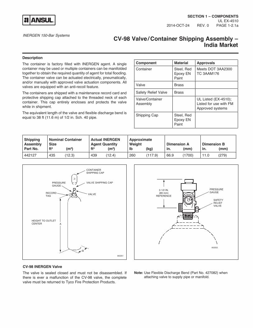
DescriptionThe container is factory filled with INERGEN agent. A single container may be used or multiple containers can be manifolded together to obtain the required quantity of agent for total flooding. The container valve can be actuated electrically, pneumatically, and/or manually with approved valve actuation components. All valves are equipped with an anti-recoil feature.The containers are shipped with a maintenance record card and protective shipping cap attached to the threaded neck of each container. This cap entirely encloses and protects the valve while in shipment.The equivalent length of the valve and flexible discharge bend is equal to 38 ft (11.6 m) of 1/2 in. Sch. 40 pipe.
CV-98 INERGEN ValveThe valve is sealed closed and must not be disassembled. If there is ever a malfunction of the CV-98 valve, the complete valve must be returned to Tyco Fire Protection Products.
Note: Use Flexible Discharge Bend (Part No. 427082) when attaching valve to supply pipe or manifold.
Component Material ApprovalsContainer Steel, Red
Epoxy EN Paint
Meets DOT 3AA2300 TC 3AAM176
Valve Brass
Safety Relief Valve Brass
Valve/Container Assembly
UL Listed (EX-4510); Listed for use with FM Approved systems
Shipping Cap Steel, Red Epoxy EN Paint
Shipping Assembly Part No.
Nominal Container Size ft³ (m³)
Actual INERGEN Agent Quantity ft³ (m³)
Approximate Weight lb (kg)
Dimension A in. (mm)
Dimension B in. (mm)
442127 435 (12.3) 439 (12.4) 260 (117.9) 66.9 (1700) 11.0 (279)
VALVE
HEIGHT TO OUTLETCENTER
002251
RECORDTAG
PRESSUREGAUGE
CONTAINERSHIPPING CAP
VALVE SHIPPING CAP
B
A
PRESSUREGAUGE
SAFETYRELIEFVALVE
002252
3 1/2 IN.(89 mm)
REFERENCE

INERGEN 150-Bar Systems
NOTES:
SECTION 1 – COMPONENTSUL EX-4510PAGE 1-2.1b REV. 0 2014-OCT-24

INERGEN 150-Bar Systems
AUTOPULSE Control System
SECTION 1 – COMPONENTSUL EX-4510
2014-OCT-24 REV. 06 PAGE 1-3a
DescriptionThe AUTOPULSE Control System provides a range of features and benefits, ranging from simple detection through counting circuits.Several models of the AUTOPULSE Control System are avail-able depending on the type of hazard being protected.Refer to the AUTOPULSE Detection and Control Systems Manual (Part No. 430261, latest revision) for detailed information concerning all AUTOPULSE Control Systems.
002195

INERGEN 150-Bar Systems
NOTES:
SECTION 1 – COMPONENTSUL EX-4510PAGE 1-3b REV. 0 2014-OCT-24

INERGEN 150-Bar Systems
AUTOMAN II-C Releasing Device
SECTION 1 – COMPONENTSUL EX-4510
2014-OCT-24 REV. 05 PAGE 1-3.1a
DescriptionThe AUTOMAN II-C Releasing Device consists of a metal enclosure which contains a spring-loaded puncture pin release mechanism, an actuation cartridge, electrical circuitry, and an input/output terminal strip for making electrical connections. The AUTOMAN II-C releasing device provides automatic pneu-matic actuation of the INERGEN System. When wired to an AUTOPULSE Control System, it will provide supervised electric detection and release. It also provides manual actuation using the strike button on the release enclosure and with the optional remote manual cable pull station. When an AUTOPULSE Control System is used, manual actuation is accomplished using an electric manual pull station.
RELEASEMECHANISM
STRIKEBUTTON
TERMINALBOARD
NAMEPLATE
000442
Shipping AssemblyPart No.
Description
17728 AUTOMAN II-C Releasing Device, 24 VDC
31492 AUTOMAN II-C Releasing Device, Explosion-Proof, 24 VDC
32525 AUTOMAN II-C Releasing Device, Explosion-Proof, 120 VAC
32526 AUTOMAN II-C Releasing Device, Weatherproof and Explosion-Proof, 24 VDC
5373 LT-30-R Nitrogen Cartridge
Component Approvals
AUTOMAN II-C Releasing Device
UL Listed for use in non-hazardous locations: UL File R5998Listed for use with FM Approved systems
AUTOMAN II-C Releasing Device (Explosion-Proof)
UL Listed for use in hazardous locations: UL File E62842Listed for use with FM Approved systems
AUTOMAN II-C Releasing Device (Weatherproof and Explosion-Proof)
Listed for use with FM Approved systems

INERGEN 150-Bar Systems
NOTES:
SECTION 1 – COMPONENTSUL EX-4510PAGE 1-3.1b REV. 0 2014-OCT-24

INERGEN 150-Bar Systems
Selector Valves
SECTION 1 – COMPONENTSUL EX-4510
2014-OCT-24 REV. 05 PAGE 1-3.3a
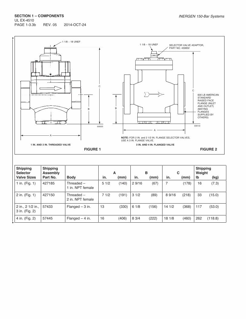
DescriptionSelector valves are used to direct the flow of INERGEN agent into a single hazard of a multiple hazard system.When pneumatic actuation is required for any selector valve, the following must be ordered separately: a Stackable Actuator Assembly (Part No. 428566) and Selector Valve Pneumatic Actuation Line Kit (Part No. 436127).When electric actuation is required for any selector valve, a Booster Actuator (Part No. 428949) and HF electric actuator (Part No. 73327) must be ordered separately.
Selector valves can be manually operated by mounting a lever actuator either directly onto the valve, onto the top of the pres-sure operated stackable actuator, or onto the top of the electric actuator. See Lever Release Actuator (page 1-4.1a) for correct actuator.Note: The Selector Valve Adaptor (Part No. 430832) can also be used to retrofit older model 1/2 in. through 2 1/2 in. selector valves (Part No. 57428-57433) when used in conjunction with Lever Release (Part No. 427207) and the Pressure-Operated Stackable Actuator (Part No. 428566).
Shipping AssemblyPart No.
Description
427185 1 in. Selector valve – threaded
427150 2 in. Selector valve – threaded
57433 2 in., 2 1/2 in., 3 in. Selector valve – flanged
57445 4 in. Selector valve – flanged
428566 Pressure-operated stackable actuator
428949 Booster actuator
Component Material Thread Size/Type Approvals1 in. Selector Valve (Used for 1/2 in., 3/4 in. and 1 in. pipe sizes)
Bronze 1 in. NPT Female UL Listed (EX-4510); Listed for use with FM Approved systems
2 in. Selector Valve (Used for 1 1/4 in., 1 1/2 in. and 2 in. pipe sizes)
Bronze 2 in. NPT Female UL Listed (EX-4510); Listed for use with FM Approved systems
2 in., 2 1/2 in., 3 in. Selector Valve
Ductile Iron 3 in. Flange American Standard Raised Face
UL Listed (EX-4510); Listed for use with FM Approved systems
4 in. Selector Valve Ductile Iron 4 in. Flange American Standard Raised Face
UL Listed (EX-4510); Listed for use with FM Approved systems
INERGEN 150-Bar SystemsSECTION 1 – COMPONENTSUL EX-4510PAGE 1-3.3b REV. 05 2014-OCT-24
006035
1 IN. AND 2 IN. THREADED VALVE
A
C
1 1/8 – 18 UNEF
B
FIGURE 1
A
008140
NOTE: FOR 2 IN. and 2 1/2 IN. FLANGE SELECTOR VALVES, USE A 3 IN. FLANGE VALVE.
SELECTOR VALVE ADAPTOR, PART NO. 430832
1 1/8 – 18 UNEF
600 LB AMERICAN STANDARD RAISED FACE FLANGE (INLET AND OUTLET) (MATING FLANGES SUPPLIED BY OTHERS)
3 IN. AND 4 IN. FLANGED VALVE
B
C
FIGURE 2
ShippingSelectorValve Sizes
ShippingAssembly Part No.
Body
A
in. (mm)
B
in. (mm)
C
in. (mm)
ShippingWeight lb (kg)
1 in. (Fig. 1) 427185 Threaded – 1 in. NPT female
5 1/2 (140) 2 9/16 (67) 7 (178) 16 (7.3)
2 in. (Fig. 1) 427150 Threaded – 2 in. NPT female
7 1/2 (191) 3 1/2 (89) 8 9/16 (218) 33 (15.0)
2 in., 2 1/2 in., 3 in. (Fig. 2)
57433 Flanged – 3 in. 13 (330) 6 1/8 (156) 14 1/2 (368) 117 (53.0)
4 in. (Fig. 2) 57445 Flanged – 4 in. 16 (406) 8 3/4 (222) 18 1/8 (460) 262 (118.8)

INERGEN 150-Bar Systems
SECTION 1 – COMPONENTSUL EX-4510
2014-OCT-24 REV. 02 PAGE 1-3.5a
Pressure-Operated Stackable Actuator
DescriptionThe Pressure-Operated Stackable Actuator (Part No. 428566) is necessary when pneumatic actuation is required on any selector valve. This actuator is installed on top of the selector valve and a 1/4 in. pressure line must be attached to the 1/8 in. pressure port on the side of the actuator. The actuator must be manually reset.Installations which utilize the pressure-operated stack-able actuator must incorporate a Selector Valve Pneumatic Actuation Line Kit (Part No. 436127) in the directional/ selector valve actuation line for each actuator. See page 1-3.8a for kit details.
Component Material Approvals
Actuator Brass UL Listed (EX-4510); Listed for use with FM Approved systems
006036
2.309 IN.(59 mm)
1/8 IN.PRESSUREPORT
1 1/8 – 18 UNEF
1 1/8 – 18 UNEF
2.926 IN.(74 mm)

INERGEN 150-Bar Systems
NOTES:
SECTION 1 – COMPONENTSUL EX-4510PAGE 1-3.5b REV. 0 2014-OCT-24
INERGEN 150-Bar Systems
SECTION 1 – COMPONENTSUL EX-4510
2014-OCT-24 REV. 01 PAGE 1-3.6a
Booster Actuator
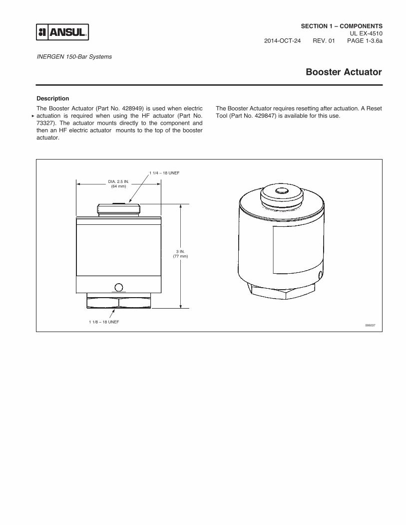
DescriptionThe Booster Actuator (Part No. 428949) is used when electric actuation is required when using the HF actuator (Part No. 73327). The actuator mounts directly to the component and then an HF electric actuator mounts to the top of the booster actuator.
The Booster Actuator requires resetting after actuation. A Reset Tool (Part No. 429847) is available for this use.
006037
DIA. 2.5 IN.(64 mm)
1 1/4 – 18 UNEF
1 1/8 – 18 UNEF
3 IN.(77 mm)

INERGEN 150-Bar Systems
NOTES:
SECTION 1 – COMPONENTSUL EX-4510PAGE 1-3.6b REV. 0 2014-OCT-24

INERGEN 150-Bar Systems
SECTION 1 – COMPONENTSUL EX-4510
2014-OCT-24 REV. 01 PAGE 1-3.7a
HF Electric Actuator
DescriptionElectrical actuation is accomplished by an HF Electric Actuator (Part No. 73327) interfaced through an AUTOPULSE Control System. This actuator can be used in hazardous, indoor envi-ronments where the ambient temperature range is between 0 °F to 130 °F (–18 °C to 54 °C). The HF electric actuator meets the requirements of N.E.C. Class I, Div. 1, Groups B, C, D and Class II, Div. 1, Groups E, F, G. A maximum of two HF electric actuators can be used on a single AUTOPULSE release circuit. When utilizing only one HF electric actuator, an in-line resistor (Part No. 73886) is required in the supervised release circuit.In auxiliary or override applications, a manual-local override valve actuator or a manual cable pull actuator can be installed on top of the HF electric actuator by removing the safety cap.An arming tool (Part No. 75433) is required to reset the actu-ator after operation. The actuator contains a standard 1/2 in. threaded female straight connector for electrical conduit hookup.
Component Material Thread Size/Type Electrical Ratings Approvals
HF Electric Actuator
Body: BrassPlunger: Stainless Steel
12 in. straight female for electrical conduit hookup
Nominal Voltage: 12 VDC @ 0.57 ampsRated Voltage: Minimum: 12.0 VDC Maximum: 14.0 VDC
UL . . . . . . . . . . . . E91021
Listed for use with FM Approved systems
4 1/2 IN. (114 mm)
2 1/4 IN. (57 mm) 001395
1 1/4 – 18
Shipping Assembly Part No.
Description
73327 HF Electric Actuator73886 In-line Resistor75433 Arming Tool

INERGEN 150-Bar Systems
NOTES:
SECTION 1 – COMPONENTSUL EX-4510PAGE 1-3.7b REV. 0 2014-OCT-24

INERGEN 150-Bar Systems
SECTION 1 – COMPONENTSUL EX-4510
2012-FEB-01 REV. 0 PAGE 1-3.8a
Selector Valve Pneumatic Actuation Line Kit
DescriptionThe Selector Valve Pneumatic Actuation Line Kit (Part No. 436127) is used to control the pressure in the actuation lines of the selector valves. One selector valve pneumatic actuation line kit is required for each Pneumatic Actuator (Part No. 428566) and must be installed within 1 ft (0.3 m) of the actuator/isolation valve.The Low Pressure Vent Plug (Part No. 436085) and Safety Relief Valve (Part No. 15677) are to be installed with a torque of 125 in.-lb (14 N•m). After system discharge, all pressure in the actuation line must be relieved by pulling the ring on the safety relief valve.
Component Material ApprovalsLow-Pressure Vent Plug
Brass UL Listed (EX-4510); Listed for use with FM Approved systems
Safety Relief Valve
Brass UL Listed (EX-4510); Listed for use with FM Approved systems
1/4 in. Close Nipple
Galvanized Steel
UL Listed (EX-4510); Listed for use with FM Approved systems
1/4 in. Tee Galvanized Steel
UL Listed (EX-4510); Listed for use with FM Approved systems
Note: The low pressure vent plug cannot be ordered separately.
008246
4 3/4 IN.(121 mm)
1 3/4 IN.(44 mm)
1/4 IN. TEE
1/4 IN. CLOSE NIPPLE
LOW PRESSURE VENT PLUG
SAFETY RELIEF VALVE
Shipping Assembly Part No.
Description
436127 Selector Valve Pneumatic Actuation Line Kit
436085 Low Pressure Vent Plug15677 Safety Relief Valve28484 1/4 in. Close Nipple27350 1/4 in. Tee

INERGEN 150-Bar Systems
NOTES:
SECTION 1 – COMPONENTSUL EX-4510PAGE 1-3.8b REV. 0 2014-OCT-24

INERGEN 150-Bar Systems
SECTION 1 – COMPONENTSUL EX-4510
2014-OCT-24 REV. 02 PAGE 1-4a
Booster Actuator/Selector Valve Adaptor
DescriptionThe Booster Actuator/Selector Valve Adaptor (Part No. 430832) is used to adapt the booster actuator to the 3 and 4 in. selector valves (Part No. 57433 and 57445). The actuator/adaptor is mounted to the selector valve and the booster (Part No. 428949) is threaded to the top of the adaptor.By adapting the booster actuator to the 3 in. and 4 in. selector valves, the valves can then be actuated by utilizing the HF electric actuator.
Shipping Assembly Part No.
Description
430832 Booster Actuator/ Selector Valve Adaptor
Note: This actuator/adaptor can also be used to retrofit older model 1/2 in. through 2 1/2 in. selector valves (Part No. 57428, 57429, 57430, 57431, 57432, and 57433) when used in conjunc-tion with the booster actuator (Part No. 428949) and the HF actuator (Part No. 73327).
Component Material Approvals
Adaptor Brass UL Listed (EX-4510); Listed for use with FM Approved systems
006518

INERGEN 150-Bar Systems
NOTES:
SECTION 1 – COMPONENTSUL EX-4510PAGE 1-4b REV. 0 2014-OCT-24

INERGEN 150-Bar Systems
Lever Release Actuator
SECTION 1 – COMPONENTSUL EX-4510
2014-OCT-24 REV. 06 PAGE 1-4.1a
DescriptionThe manual lever release actuator provides a manual means of actuating container valves and selector valves. This can be accomplished by direct manual actuation of its pull lever or cable actuation when used in conjunction with a remote manual pull station. When used with a remote manual pull station, the pull station must contain the components necessary to meet the actuator lever traveling requirements of 7 in. (178 mm).The actuator is shipped with ring pin and chain attached. If the ring pin is not required, it must be removed. Failure to remove the ring pin/chain assembly will prevent system actuation if a remote cable pull actuation system is employed and the ring pin is accidentally installed in the actuator.Four actuators are available. Each is designed for a specific component.
3 7/8 IN.(98 mm)
DEPTH: 3 IN. (76 mm)
3 7/8 IN.*(98 mm)
000897
* Add 1 9/16 in. (39 mm) to height when lever is in the straight up position.
PIN
TO RELEASE: LEVER TRAVELS
7 IN. (178 mm)
Shipping Assembly Part No.
Description
42484 Lever Release (1 1/4-18 mounting thread) – Mounts directly to pressure actuator on 2 1/2 in., 3 in. and 4 in. selector valves.
423309 Lever Release (1 1/8-18 mounting thread) – Mounts directly to a CV-98 electric actuator. Mounts directly to a CV-98 container valve.
70846 Lever Release (1 1/4-18 mounting thread) – Mounts directly to an HF electric actuator.
427207 Lever Release (1 1/8-18 mounting thread) – Mounts directly to the 1 in. and 2 in. selector valves. Mounts directly to pressure-operated stackable actuator for 1 in. and 2 in. selector valves. Actuator has the handle painted red.
Component Material ApprovalsAll Manual Cable-pull Actuators
Brass with Stainless Steel Pin
UL Listed (EX-4510); Listed for use with FM Approved systems

INERGEN 150-Bar Systems
NOTES:
SECTION 1 – COMPONENTSUL EX-4510PAGE 1-4.1b REV. 0 2014-OCT-24
INERGEN 150-Bar Systems
SECTION 1 – COMPONENTSUL EX-4510
2014-OCT-24 REV. 04 PAGE 1-5a
Manual Pull Box
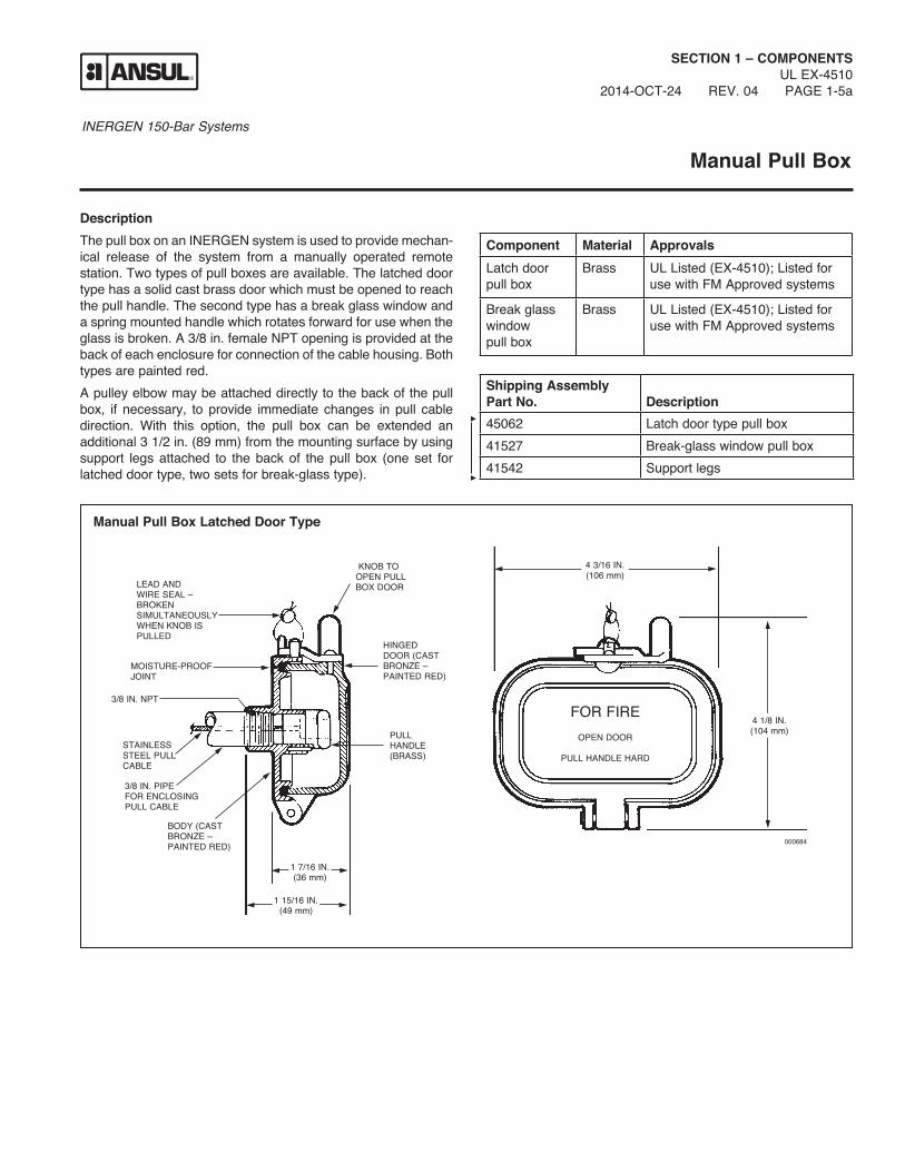
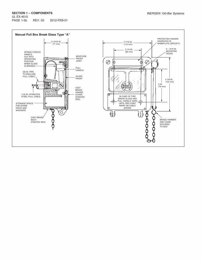
DescriptionThe pull box on an INERGEN system is used to provide mechan-ical release of the system from a manually operated remote station. Two types of pull boxes are available. The latched door type has a solid cast brass door which must be opened to reach the pull handle. The second type has a break glass window and a spring mounted handle which rotates forward for use when the glass is broken. A 3/8 in. female NPT opening is provided at the back of each enclosure for connection of the cable housing. Both types are painted red.A pulley elbow may be attached directly to the back of the pull box, if necessary, to provide immediate changes in pull cable direction. With this option, the pull box can be extended an additional 3 1/2 in. (89 mm) from the mounting surface by using support legs attached to the back of the pull box (one set for latched door type, two sets for break-glass type).
Manual Pull Box Latched Door Type
KNOB TOOPEN PULLBOX DOORLEAD AND
WIRE SEAL –BROKENSIMULTANEOUSLYWHEN KNOB ISPULLED
HINGEDDOOR (CASTBRONZE –PAINTED RED)
MOISTURE-PROOFJOINT
3/8 IN. NPT
PULLHANDLE(BRASS)
FOR FIREOPEN DOOR
PULL HANDLE HARDSTAINLESSSTEEL PULLCABLE
3/8 IN. PIPEFOR ENCLOSINGPULL CABLE
BODY (CASTBRONZE –PAINTED RED)
1 7/16 IN.(36 mm)
1 15/16 IN.(49 mm)
4 3/16 IN.(106 mm)
000684
4 1/8 IN.(104 mm)
Shipping Assembly Part No.
Description
45062 Latch door type pull box41527 Break-glass window pull box41542 Support legs
Component Material ApprovalsLatch door pull box
Brass UL Listed (EX-4510); Listed for use with FM Approved systems
Break glass window pull box
Brass UL Listed (EX-4510); Listed for use with FM Approved systems
INERGEN 150-Bar SystemsSECTION 1 – COMPONENTSUL EX-4510PAGE 1-5b REV. 03 2012-FEB-01
Manual Pull Box Break Glass Type “A”
SPRING FORCESHANDLEOUT INTOOPERATINGPOSITIONWHEN GLASSIS BROKEN
MOISTUREPROOFJOINT
PULLHANDLE
GLASSFRONT
3/8 IN. PIPETO ENCLOSEPULL CABLE
1/16 IN. STAINLESS STEEL PULL CABLE
CASTBRASSHINGEDCOVER(PAINTEDRED)
CAST BRASSBODY(PAINTED RED)
STOWAGE SPACEFOR SPAREDISCS ANDWASHERS
2 13/16 IN.(71 mm)
PROTECTED HAZARDENGRAVED INNAMEPLATE (SPECIFY)
4 7/16 IN.(112 mm)
3 1/4 IN.(82 mm)
4 – 3/16 IN.MOUNTING HOLES
IN CASE OF FIREBREAK GLASS ANDPULL HANDLE HARD
UNTIL RED PAINTMARK ON CABLE
SHOWS
BRASS HAMMERAND CHAINSECUREDTO BOX
4 7/8 IN.(123 mm)
3 IN.(76 mm)

INERGEN 150-Bar Systems
SECTION 1 – COMPONENTSUL EX-4510
2014-OCT-24 REV. 04 PAGE 1-6a
Cable with Swaged End Fitting
DescriptionThe 1/16 in. diameter cable is used to attach remote manual pull boxes to container valves, pull equalizers and control boxes. The cable is constructed of stranded, stainless steel wire. The cable is available in lengths of 50, 100, and 150 ft (15.2, 30.5, and 45.7 m). The cable assemblies include a brass swaged end fitting for attaching to the remote pull box.
Note: The strength of the end fitting exceeds the breaking point of the cable.
HANDLE
CABLEEND(BRASS)
COUPLING
SLOT IN COUPLINGFOR INSTALLATIONOF CABLE ENDFITTING
STAINLESS STEEL CABLE WITH SWAGEDCABLE END FOR PULL BOX, CABLE ENDHAVING RED PAINT MARK 000689
Component Material ApprovalsCable Assembly
Cable: Stainless SteelSwaged Fitting: Brass
UL Listed (EX-4510); Listed for use with FM Approved systems
Shipping Assembly Part No.
Description
42104 50 ft (15.2 m), 1/16 in. (1.6 mm) cable with swaged end fitting
42109 100 ft (30.5 m), 1/16 in. (1.6 mm) cable with swaged end fitting
42113 150 ft (45.7 m), 1/16 in. (1.6 mm) cable with swaged end fitting

INERGEN 150-Bar Systems
NOTES:
SECTION 1 – COMPONENTSUL EX-4510PAGE 1-6b REV. 0 2014-OCT-24

INERGEN 150-Bar Systems
SECTION 1 – COMPONENTSUL EX-4510
2014-OCT-24 REV. 04 PAGE 1-7a
Corner Pulley
DescriptionThe corner pulley is required on an INERGEN system whenever a mechanical release pull cable run involves a change in direction. Corner pulleys are installed as part of the cable housing (pipe or conduit) and provide 90° direction changes with minimal force loss and no induced kinking.Two types of corner pulleys are available. One is made of die cast aluminum, has a ball bearing roller, and uses compression fittings for 1/2 in. EMT connections. The second type is made of forged brass and is threaded for 3/8 in. NPT pipe. Two styles of forged brass corner pulleys are available: one with a brass wheel and one with a nylon wheel. Both styles of brass pulleys are watertight. The brass wheel corner pulley is designed for location inside or outside the protected space. The nylon wheel corner pulley is designed for location only outside the hazard space. Thread adaptors are available to simplify the installation.
Shipping Assembly Part No.
Description
423250 Aluminum corner pulley42678 Brass corner pulley (nylon wheel)45515 Brass corner pulley (brass wheel)40696 Thread adaptor – (brass pulley only)
Component
Material
Thread Size/ Type
Approvals
Corner Pulley
Body: AluminumRoller: Stainless
Steel
1/2 in. EMT UL Listed (EX-4510); Listed for use with FM Approved systems
Corner Pulley
Body: BrassWheel: Brass
3/8 in. NPT UL Listed (EX-4510); Listed for use with FM Approved systems
Corner Pulley
Body: BrassWheel: Nylon
3/8 in. NPT UL Listed (EX-4510); Listed for use with FM Approved systems
Corner Pulley For 1/2 in. EMT Aluminum(Part No. 423250)
2 11/16 IN.(17 mm)
3/8 IN. NPT1 5/32 IN.(29 mm)
LEAD-CLADCOPPERGASKET
3/8 IN. PIPE
REMOVABLEFACE FORRUNNING CABLE
ADAPTOR
00690
1 1/8
IN.
(28
mm)
GLANDBODY
COVER
SELF-TAPPING SCREW
BALL BEARING SHEAVE
2 7/8 IN.(73 mm)
2 7/8 IN.(73 mm)
001815
A A
4 3/16 IN.(106 mm)
Forged Brass Watertight Corner Pulley, Sheave Type (Part No. 42678 and 45515)

INERGEN 150-Bar Systems
NOTES:
SECTION 1 – COMPONENTSUL EX-4510PAGE 1-7b REV. 04 2014-OCT-24

INERGEN 150-Bar Systems
Dual/Triple Control Boxes
SECTION 1 – COMPONENTSUL EX-4510
2014-OCT-24 REV. 03 PAGE 1-8a
DescriptionThe dual/triple control boxes allow manual actuation of a container valve from two or three remote pull stations. Two styles of control boxes are available. Part No. 42784 is 13 3/4 in. (349 mm) long and Part No. 43166 is 20 3/4 in. (527 mm) long. Both styles can be used for container valve actua-tion. The inlet and outlet connections are threaded for 3/8 in. pipe. If 1/2 in. EMT conduit connections are required, an adaptor (Part No. 45780) is available.
* Adaptors furnished for use with 1/2 in. EMT – Part No. 45780
Shipping Assembly Part No.
Description
42784 Dual/triple control box (short)43166 Dual/triple control box (long)
Component Material Thread Size/Type ApprovalsControl Box (short) Steel 3/8 in. NPT Female UL Listed (EX-4510); Listed for use with
FM Approved systemsControl Box (long) Steel 3/8 in. NPT Female UL Listed (EX-4510); Listed for use with
FM Approved systems
Part No. 42784
Junction Box(Shown Without Cover)
End View
5/8 IN.(15 mm)
3 1/4 IN.(82 mm)
1/2 IN.(12 mm)
2 3/4 IN.(69 mm)
1 7/8 IN.(47 mm)
11/16 IN.(17 mm)
REMOVABLE COVER
12 1/4 IN.(311 mm)
13 3/4 IN. (349 mm)(OVERALL)
DIRECTION OF PULL
CABLE-PULL FROMPULL-BOXESFLEXIBLE TRANSPARENT
PROTECTION RING
CABLE CLAMP
CABLE – PULL TOCONTAINER RELEASE
3/8 IN. PIPE OR1/2 IN. E.M.T.*
4 – 9/32 IN. (7.1 mm)MOUNTING HOLES
CLAMP WITHINBLACK AREA
1 IN.(25 mm)
000685

INERGEN 150-Bar SystemsSECTION 1 – COMPONENTSUL EX-4510PAGE 1-8b REV. 03 2014-OCT-24
* Adaptors furnished for use with 1/2 in. EMT – Part No. 45780
Part No. 43166
Junction Box(Shown Without Cover)
End View
5/8 IN.(15 mm)
3 1/4 IN.(82 mm)
1/2 IN.(12 mm)
2 3/4 IN.(69 mm)
1 7/8 IN.(47 mm)
11/16 IN.(17 mm)
REMOVABLE COVER
1 IN.(25 mm)
19 1/4 IN.(488 mm)
20 3/4 IN.(527 mm)
DIRECTION OF PULL
CABLE-PULL FROMPULL-BOXESFLEXIBLE TRANSPARENT
PROTECTION RING
CABLE CLAMPCABLE – PULL TOCONTAINER RELEASE
3/8 IN. PIPE OR1/2 IN. E.M.T.*
4 – 9/32 IN. (7.1 mm)MOUNTING HOLES
CLAMP WITHINBLACK AREA
000685

INERGEN 150-Bar Systems
SECTION 1 – COMPONENTSUL EX-4510
2014-OCT-24 REV. 06 PAGE 1-9a
Remote Cable Pull Equalizer
DescriptionThe remote cable pull equalizer is used in systems where manual actuation of the container valve and operation of a selector valve must be accomplished at the same time. The pull equalizer is mounted in the remote pull station cable line. By pulling the remote pull box, the cable attached to the pull equal-izer will pull the internal cable clamp in the pull equalizer which in turn will pull the cables attached to the container valve and selector valve, causing them to operate.Two styles of cable pull equalizers are available. Part No. 42791 is 13 3/4 in. (349 mm) long and Part No. 43168 is 20 3/4 in. (527 mm) long. Only the longest equalizer (Part No. 43168) can be used for valves utilizing sectors. The inlet and outlet connections are threaded for 3/8 in. pipe. If 1/2 in. EMT conduit connections are required, an adaptor (Part No. 45780) is available.
Part No. 42791
Equalizer Box(Shown Without Cover)
End View
3 1/4 IN.(82 mm)
2 3/4 IN.(69 mm)
1 7/8 IN.(47 mm)
11/16 IN.(17 mm)
REMOVABLE COVER
1 IN.(25 mm)
12 1/4 IN.(311 mm)
13 3/4 IN. (34.9 mm)(OVERALL)
DIRECTION OF PULL
CABLE TO PULL BOX
FLEXIBLE TRANSPARENTPROTECTION RING
CABLE CLAMP
4 – 9/32 IN. (7.1 mm)MOUNTING HOLES
CABLE FROM CONTAINER AND VALVE RELEASES
* Adaptors furnished for use with 1/2 in. E.M.T. – Part No. 45780
3/8 IN. PIPE OR1/2 IN. E.M.T.*
Shipping Assembly Part No.
Description
42791 Remote cable pull equalizer (short)
43168 Remote cable pull equalizer (long)
Component Material Thread Size/Type Approvals
Pull Equalizer (short)
Steel 3/8 in. NPT Female
UL Listed (EX-4510); Listed for use with FM Approved systems
Pull Equalizer (long)
Steel 3/8 in. NPT Female
UL Listed (EX-4510); Listed for use with FM Approved systems

INERGEN 150-Bar SystemsSECTION 1 – COMPONENTSUL EX-4510PAGE 1-9b REV. 06 2014-OCT-24
* Adaptors furnished for use with 1/2 in. E.M.T. – Part No. 45780
Part No. 43168
Equalizer Box(Shown Without Cover)
End View
3 1/4 IN.(82 mm)
2 3/4 IN.(69 mm)
1 7/8 IN.(47 mm)
11/16 IN.(17 mm)
REMOVABLE COVER
1 IN.(25 mm)
19 1/4 IN.(488 mm)
20 3/4 IN. (527 mm)(OVERALL)
DIRECTION OF PULL
CABLE TO PULL BOX
FLEXIBLE TRANSPARENTPROTECTION RING
CABLE CLAMP
CABLE FROM CONTAINER AND VALVE RELEASES
4 – 9/32 IN. (7.1 mm)MOUNTING HOLES
3/8 IN. PIPE OR1/2 IN. E.M.T.*

INERGEN 150-Bar Systems
Pressure Bleeder Plug – 1/4 in.
SECTION 1 – COMPONENTSUL EX-4510
2012-FEB-01 REV. 03 PAGE 1-11a
DescriptionThe pressure bleeder plug must be used to relieve the pressure in closed actuation lines. The plug relieves the pressure through a small orifice. This slow relief of pressure does not affect the function of the actuation line.
CAUTIONPressure Bleeder Plug (Part No. 42175) must not be installed anywhere in the directional/selector valve actuation line as the directional/selector valve may not remain open during a complete system discharge, potentially interfering with the ability of the system to suppress a fire.
ORIFICE
1/4 IN. NPT
001839
Shipping Assembly Part No.
Description
42175 Pressure Bleeder Plug
Component Material Thread Size/Type Approvals
Bleeder Plug Brass 1/4 in. NPT Male
UL Listed (EX-4510); Listed for use with FM Approved systems
INERGEN 150-Bar Systems
NOTES:
SECTION 1 – COMPONENTSUL EX-4510PAGE 1-11b REV. 0 2014-OCT-24

INERGEN 150-Bar Systems
SECTION 1 – COMPONENTSUL EX-4510
2014-OCT-24 REV. 07 PAGE 1-12a
Flexible Discharge Bend
DescriptionThe valve Flexible Discharge Bend (Part No. 427082) is a 5/8 in. (15.9 mm) I.D. extra-heavy flexible hose which connects the valve discharge outlet to the fixed piping or header manifold. The discharge bend has a special female thread for connecting to the valve outlet and a male 1/2 in. NPT thread for connecting to the fixed piping or manifold. The discharge bend will withstand a pressure of 9000 psi (621 bar). Its flexible connection allows for easy alignment of multiple container banks to fixed piping. Each bend has a built-in check valve that prevents loss of agent should the system discharge while any container is removed.The equivalent length of this hose is equal to 18 ft (5.5 m) of 1/2 in. Sch. 40 pipe.
18 7/8 IN.(479 mm)
MANIFOLD END
009486
1/2 IN. NPTMALE COUPLING
FEMALE VALVE END ADAPTOR (BRASS)
VALVE END
CHECK
GASKETSWAGE ON
Shipping Assembly Part No.
Description
427082 Flexible discharge bend
42430 Washer (for previous adaptor design)
437919 Gasket
422509 Hydrostatic Test Adaptor
Component MaterialThread Size/Type
Valve End Adaptor Manifold End Approvals
5/8 in. Flexible Discharge Bend
SAE 100 R2 Type AT
Special to mate with CV90 and CV-98 Valve
1/2 in. NPT Male UL Listed (EX-4510); Listed for use with FM Approved systems
Valve End Adaptor Comparison
009479a 009479b
PREVIOUS ADAPTOR DESIGN (REQUIRED WASHER – PART NO. 42430)
NEW ADAPTOR DESIGN (REQUIRED GASKET – PART NO. 437919)

INERGEN 150-Bar Systems
NOTES:
SECTION 1 – COMPONENTSUL EX-4510PAGE 1-12b REV. 0 2014-OCT-24
INERGEN 150-Bar Systems
SECTION 1 – COMPONENTSUL EX-4510
2014-OCT-24 REV. 06 PAGE 1-13a
Check Valves
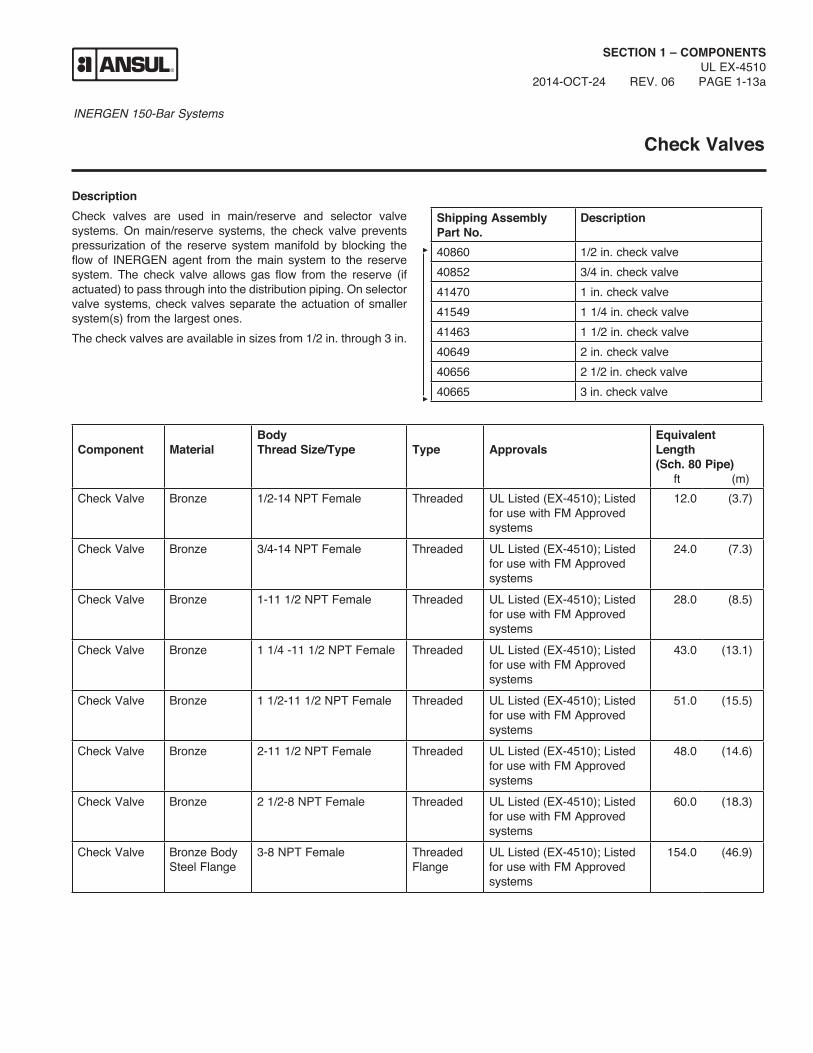
DescriptionCheck valves are used in main/reserve and selector valve systems. On main/reserve systems, the check valve prevents pressurization of the reserve system manifold by blocking the flow of INERGEN agent from the main system to the reserve system. The check valve allows gas flow from the reserve (if actuated) to pass through into the distribution piping. On selector valve systems, check valves separate the actuation of smaller system(s) from the largest ones. The check valves are available in sizes from 1/2 in. through 3 in.
Shipping Assembly Part No.
Description
40860 1/2 in. check valve40852 3/4 in. check valve41470 1 in. check valve41549 1 1/4 in. check valve41463 1 1/2 in. check valve40649 2 in. check valve40656 2 1/2 in. check valve40665 3 in. check valve
Component
Material
BodyThread Size/Type
Type Approvals
Equivalent Length (Sch. 80 Pipe) ft (m)
Check Valve Bronze 1/2-14 NPT Female Threaded UL Listed (EX-4510); Listed for use with FM Approved systems
12.0 (3.7)
Check Valve Bronze 3/4-14 NPT Female Threaded UL Listed (EX-4510); Listed for use with FM Approved systems
24.0 (7.3)
Check Valve Bronze 1-11 1/2 NPT Female Threaded UL Listed (EX-4510); Listed for use with FM Approved systems
28.0 (8.5)
Check Valve Bronze 1 1/4 -11 1/2 NPT Female Threaded UL Listed (EX-4510); Listed for use with FM Approved systems
43.0 (13.1)
Check Valve Bronze 1 1/2-11 1/2 NPT Female Threaded UL Listed (EX-4510); Listed for use with FM Approved systems
51.0 (15.5)
Check Valve Bronze 2-11 1/2 NPT Female Threaded UL Listed (EX-4510); Listed for use with FM Approved systems
48.0 (14.6)
Check Valve Bronze 2 1/2-8 NPT Female Threaded UL Listed (EX-4510); Listed for use with FM Approved systems
60.0 (18.3)
Check Valve Bronze Body Steel Flange
3-8 NPT Female Threaded Flange
UL Listed (EX-4510); Listed for use with FM Approved systems
154.0 (46.9)

INERGEN 150-Bar SystemsSECTION 1 – COMPONENTSUL EX-4510PAGE 1-13b REV. 06 2014-OCT-24
A
B
BONNET
BODY
SPRING
CHECK
A
B
CHECK
BODY
BONNETSPRING
C
Check Valve – Threaded Valve Size
Dimension A in. (mm)
Dimension Bin. (mm)
1/2 in. 3 (76) 2 5/8 (66)3/4 in. 3 5/8 (92) 3 1/8 (79)1 in. 4 1/8 (104) 3 3/4 (95)1 1/4 in. 5 (127) 4 1/2 (114)1 1/2 in. 5 1/2 (139) 5 1/8 (130)2 in. 6 1/2 (165) 5 3/4 (146)2 1/2 in. 8 (203) 6 3/4 (171)
Check Valve – Threaded FlangeValve Size
Dimension A in. (mm)
Dimension Bin. (mm)
Dimension Cin. (mm)
3 in. 11 1/2 (292) 15 (381) 9 1/2 (241)

INERGEN 150-Bar Systems
1/2 in. Manifold Relief Valve
SECTION 1 – COMPONENTSUL EX-4510
2014-OCT-24 REV. 0 PAGE 1-13.1a
DescriptionThe manifold relief valve will release pressure buildup in the manifold line. This slow release of pressure does not affect the function of the manifold line.Burst Pressure: 2,900 – 3,360 psi (200 – 232 bar)
SAFETY DISK NUT
1/2 – 14 NPT
002740
1/2 in. Manifold Relief Valve
7/8 IN.(22 mm)
1 1/2 IN.(38 mm)
Shipping Assembly Part No.
Description
418378 1/2 in. manifold relief valve
Component Material Approvals1/2 in. ManifoldRelief Valve
Brass UL Listed(EX-4510)

INERGEN 150-Bar Systems
NOTES:
SECTION 1 – COMPONENTSUL EX-4510PAGE 1-13.1b REV. 0 2014-OCT-24

INERGEN 150-Bar Systems
SECTION 1 – COMPONENTSUL EX-4510
2012-FEB-01 REV. 03 PAGE 1-14a
Header Vent Plug
DescriptionThe header vent plug is used to release low pressure build- up that may occur in a closed system utilizing selector valves or check valves. The header vent plug should also be installed on the container sides of the check valves on both main and reserve systems to relieve any pressure that may leak past the check valve and accidentally actuate the reserve system while the main system is discharging.
CAUTIONA header vent plug must be installed in all closed sections of the system manifold(s). The omission of a header vent plug may cause the manifold to build pressure. This could result in the actuation of a system container, which would then cause all containers in that specific system to actuate.
000707
SPRING
CHECK SEAL
CHECK CUP
1/2 IN. NPT
STEM
BODY
WASHER
29/32 IN.(23 mm)7/8 IN.
(22 mm)
Shipping Assembly Part No.
Description
40309 Header vent plug
Component
Material
Thread Size/Type
Approvals
Vent Plug Body: BrassSpring: BronzeSeal: Neoprene
1/2 in. NPT Male
UL Listed (EX-4510); Listed for use with FM Approved systems

INERGEN 150-Bar Systems
NOTES:
SECTION 1 – COMPONENTSUL EX-4510PAGE 1-14b REV. 0 2014-OCT-24

INERGEN 150-Bar Systems
Stainless Steel Actuation Hose
SECTION 1 – COMPONENTSUL EX-4510
2014-OCT-24 REV. 06 PAGE 1-14.1a
DescriptionThe Stainless Steel Actuation Hose is used to connect the actuation line flared tees between each agent tank. The hose has the same thread, 7/16-20, as the flared tees. The actuation hose allows flexibility between the rigid actuation piping and the tank valve.
Additional actuation fittings are available:Part No. Description32334 Male Elbow (7/16-20 x 1/8 in. NPT)418359 Male Tee (7/16-20 x 7/16-20 x 1/8 in. NPT)32338 Male Straight Connector (7/16-20 x 1/4 in. NPT)
24 IN.(610 mm)
7/16-20
000433
7/16-20
Shipping Assembly Part No.
Description
31809 16 in. (406 mm) Stainless Steel Hose
32335 20 in. (508 mm) Stainless Steel Hose
32336 24 in. (609 mm) Stainless Steel Hose
Component Material Thread Size ApprovalsStainless Steel Hose
Stainless Steel
Female 7/16-20 (Both ends)
UL Listed (EX-4510); Listed for use with FM Approved systems

INERGEN 150-Bar Systems
NOTES:
SECTION 1 – COMPONENTSUL EX-4510PAGE 1-14.1b REV. 0 2014-OCT-24

INERGEN 150-Bar Systems
SECTION 1 – COMPONENTSUL EX-4510
2012-FEB-01 REV. 08 PAGE 1-15a
Pressure Reducer/Union
DescriptionThe pressure reducer/union is required to restrict the flow of INERGEN agent thus reducing the agent pressure down stream of the union. The 3000 psi (206.9 bar) NSCWP union contains a stainless steel orifice plate which is drilled to the specific size hole required based on the flow calcu-lation.* The orifice plate provides readily visible orifice identification. The orifice union is available in six sizes: 1/2 in., 3/4 in., 1 in., 1 1/4 in., 1 1/2 in., and 2 in. NPT.All pressure reducer/unions must be installed in the piping with the orifice identification tab on the pressure inlet side of the system. The 1 1/4 in., 1 1/2 in. and 2 in. orifice unions must be installed per the direction of the flow arrow stamped on the body.
VISIBLE ORIFICEIDENTIFICATION 002197
DIRECTIONOF FLOW
C
A
B
Note: Refer to “Nozzle/Pressure Reducer Range Chart” in Section 5 - Design for detailed orifice range information.
* Orifice diameter must be specified when placing order.
Shipping Assembly Part No.
Description
A in. (mm)
B in. (mm)
C in. (mm)
416677 1/2 in. NPT pressure reducer/union 2.06 (52) 1.18 (29) 1.95 (49)416678 3/4 in. NPT pressure reducer/union 2.38 (61) 1.50 (38) 2.38 (61)416679 1 in. NPT pressure reducer/union 2.63 (67) 1.78 (45) 2.77 (70)416680 1 1/4 in. NPT pressure reducer/union 2.94 (75) 2.04 (52) 3.31 (84)416681 1 1/2 in. NPT pressure reducer/union 3.31 (84) 2.31 (59) 3.70 (94)416682 2 in. NPT pressure reducer/union 3.56 (90) 2.85 (72) 4.39 (112)
Component Material Thread Size - NPT ApprovalsPressure Reducer/ Union
Body: Forged SteelOrifice Plate: Stainless Steel
1/2 in., 3/4 in., 1 in., 1 1/4 in., 1 1/2 in., 2 in.
UL Listed (EX-4510); Listed for use with FM Approved systems

INERGEN 150-Bar Systems
NOTES:
SECTION 1 – COMPONENTSUL EX-4510PAGE 1-15b REV. 0 2014-OCT-24

INERGEN 150-Bar Systems
Pressure Reducer/Nipple
SECTION 1 – COMPONENTSUL EX-4510
2012-FEB-01 REV. 06 PAGE 1-15.1a
DescriptionThe pressure reducer/nipple is required to restrict the flow of INERGEN agent thus reducing the agent pressure downstream of the nipple. The nipple contains an orifice which is drilled to the specific size hole required based on the flow calculation.* The pressure reducer/nipple part number and orifice size are stamped on the body hex. The orifice nipple is available in two sizes: 2 1/2 in., and 3 in. NPT.
Note: Refer to “Nozzle/Pressure Reducer Range Chart” in Section 5 - Design for detailed orifice range information.
* Orifice diameter must be specified when placing order.
A
002198
Shipping Assembly Part No.
Description
417057 2 1/2 in. NPT pressure reducer/nipple
417058 3 in. NPT pressure reducernipple
Nipple Size Hex Size “A” Dim.2 1/2 in. 3 in. 4 3/8 in. (111 mm) 3 in. 3 1/2 in. 4 1/2 in. (114 mm)
Component Material Thread Size ApprovalsPressure Reducer/ Nipple
Body: Brass
2 1/2, 3 in. NPT UL Listed (EX-4510); Listed for use with FM Approved systems

INERGEN 150-Bar Systems
NOTES:
SECTION 1 – COMPONENTSUL EX-4510PAGE 1-15.1b REV. 0 2014-OCT-24
INERGEN 150-Bar Systems
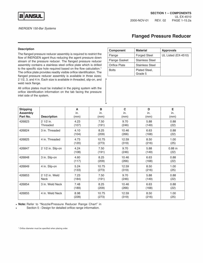
DescriptionThe flanged pressure reducer assembly is required to restrict the flow of INERGEN agent thus reducing the agent pressure down stream of the pressure reducer. The flanged pressure reducer assembly contains a stainless steel orifice plate which is drilled to the specific size hole required based on the flow calculation.* The orifice plate provides readily visible orifice identification. The flanged pressure reducer assembly is available in three sizes; 2 1/2, 3, and 4 in. Each size is available in threaded, slip-on, and weld neck flange. All orifice plates must be installed in the piping system with the orifice identification information on the tab facing the pressure inlet side of the system.
Flanged Pressure Reducer
SECTION 1 – COMPONENTSUL EX-4510
2000-NOV-01 REV. 02 PAGE 1-15.2a
Note: Refer to “Nozzle/Pressure Reducer Range Chart” in Section 5 - Design for detailed orifice range information.
* Orifice diameter must be specified when placing order.
Component Material ApprovalsFlange Forged Steel UL Listed (EX-4510)Flange Gasket Stainless SteelOrifice Plate Stainless SteelBolts Plated Steel,
Grade 5
Shipping Assembly Part No.
Description
A in.
(mm)
B in.
(mm)
C in.
(mm)
D in.
(mm)
E in.
(mm)426823 2 1/2 in.
Threaded4.23(107)
7.50(191)
9.70(246)
5.88(149)
0.88(22)
426824 3 in. Threaded 4.10(104)
8.25(209)
10.46(266)
6.63(168)
0.88(22)
426825 4 in. Threaded 4.73(120)
10.75(273)
12.59(319)
8.50(216)
1.00(25)
426847 2 1/2 in. Slip-on 4.24(108)
7.50(191)
9.70(246)
5.88(149)
0.88 in(22)
426848 3 in. Slip-on 4.60(117)
8.25(209)
10.46(266)
6.63(168)
0.88(22)
426849 4 in. Slip-on 5.24(133)
10.75(273)
12.59(319)
8.50(216)
1.00(25)
426853 2 1/2 in. Weld Neck
7.23(184)
7.50(191)
9.70(246)
5.88(149)
0.88(22)
426854 3 in. Weld Neck 7.48(189)
8.25(209)
10.46(266)
6.63(168)
0.88(22)
426855 4 in. Weld Neck 8.98(228)
10.75 (273)
12.59(319)
8.50(216)
1.00(25)

INERGEN 150-Bar SystemsSECTION 1 – COMPONENTSUL EX-4510PAGE 1-15.2b REV. 02 2000-NOV-01
Threaded
A
003655
Slip-On
A
003656
Weld Neck
A
003653
C
003654
D
E(8 PLACES)
B

INERGEN 150-Bar Systems
Orifice Plates
SECTION 1 – COMPONENTSUL EX-4510
2000-NOV-01 REV. 01 PAGE 1-15.3a
DescriptionOrifice plate shipping assemblies are available as replacement plates. Replacement plates may be required in situations where the piping and pressure reducer size can stay the same but because of some hazard change, the size of the orifice in the pressure reducer must change.The orifice size must be specified when ordering the orifice plate.Note: Replacement orifice plates for orifice nipples are not
available as the plate is a permanent fixture of the part.Note: Refer to “Nozzle/Pressure Reducer Range Chart” in
Section 5 - Design for detailed orifice range inform ation.
Part No. Description418095 1/2 in. Replacement Orifice Plate418096 3/4 in. Replacement Orifice Plate418097 1 in. Replacement Orifice Plate418098 1 1/4 in. Replacement Orifice Plate418099 1 1/2 in. Replacement Orifice Plate418100 2 in. Replacement Orifice Plate426984 2 1/2 in. Replacement Orifice Plate426985 3 in. Replacement Orifice Plate426986 4 in. Replacement Orifice Plate

INERGEN 150-Bar Systems
NOTES:
SECTION 1 – COMPONENTSUL EX-4510PAGE 1-15.3b REV. 0 2014-OCT-24

INERGEN 150-Bar Systems
Single Mating Flanges
SECTION 1 – COMPONENTSUL EX-4510
2014-OCT-24 REV. 02 PAGE 1-15.4a
DescriptionSingle mating flanges are available for field assembly to the ANSUL selector valves and the ANSUL flanged pressure reduc-ers. These single, flanged shipping assemblies are available in threaded, slip-on, and weld neck, in 2 1/2 in., 3 in., and 4 in. sizes. Each shipping assembly includes a flange, a stainless steel gasket, 8 bolts, and 8 nuts.
Component Material ApprovalsFlange Forged Steel UL Listed (EX-4510)
Flange Gasket Stainless Steel
Bolts/Nuts Plated Steel, Grade 5
Shipping Assembly Part No.
Description
426856 2 1/2 in. Threaded Flange426857 3 in. Threaded Flange426858 4 in. Threaded Flange426859 2 1/2 in. Slip on Flange426860 3 in. Slip-on Flange426861 4 in. Slip-on Flange426862 2 1/2 in. Weld Neck426863 3 in. Weld Neck426864 4 in. Weld Neck
009480
Ø “A” (REF.)
Ø “B” (REF.)
Part No.
Flange Size in.
Dia. A in. (mm)
Dia. B in. (mm)
426826 2 1/2 5.88 (149) 0.88 (22.4)40570 3 6.63 (168) 0.88 (22.4)426827 4 8.50 (216) 1 (25.4)426835 2 1/2 5.88 (149) 0.88 (22.4)426836 3 6.63 (168) 0.88 (22.4)426837 4 8.50 (216) 1 (25.4)426838 2 1/2 5.88 (149) 0.88 (22.4)42525 3 6.63 (168) 0.88 (22.4)426840 4 8.50 (216) 1 (25.4)

INERGEN 150-Bar Systems
NOTES:
SECTION 1 – COMPONENTSUL EX-4510PAGE 1-15.4b REV. 0 2014-OCT-24

INERGEN 150-Bar Systems
SECTION 1 – COMPONENTSUL EX-4510
2014-OCT-24 REV. 09 PAGE 1-16a
360° Discharge Nozzles
DescriptionDischarge nozzles are designed to direct the discharge of INERGEN agent using the stored pressure from the containers. Ten sizes of nozzles are available. The system design specifies the orifice size* to be used for proper flow rate and distribution pattern. The nozzle selection depends on the hazard and loca-tion to be protected. Standard nozzles are constructed of brass.Note: 2, 2 1/2, and 3 in. nozzles are not recommended in areas that are subject to damage by high velocity discharges, such as suspended ceiling tiles.
* Orifice diameter must be specified when ordering nozzle.
**UL/ULC listed only.
Shipping AssemblyPart No.*
Description
417908 1/4 in. NPT nozzle**417723 3/8 in. NPT nozzle**417362 1/2 in. NPT nozzle417363 3/4 in. NPT nozzle417364 1 in. NPT nozzle417365 1 1/4 in. NPT nozzle417366 1 1/2 in. NPT nozzle426155 2 in. NPT nozzle426156 2 1/2 in. NPT nozzle426137 3 in. NPT nozzle
Component Material Thread Size ApprovalsNozzle Body:
Brass1/4**, 3/8**, 1/2, 3/4, 1, 1 1/4, 1 1/2, 2, 2 1/2, 3 in. NPT
UL Listed (EX-4510); Listed for use with FM Approved systems
B
C
A
Note: Refer to “Nozzle/Pressure Reducer Range Chart” in Section 5 - Design for detailed orifice range information.
Dimensions Thread Size
Ain. (mm)
Bin. (mm)
Cin. (mm)
Hex in.
1/4 in. 5/8(15.88)
1 9/16(39.69)
21/32(16.67)
5/8
3/8 in. 3/4(19.05)
1 5/8(41.28)
23/32(18.26)
3/4
1/2 in. 15/16(23.81)
1 31/32(50.01)
27/32(21.43)
15/16
3/4 in. 1 1/8(28.58)
2 5/32(54.77)
7/8(22.23)
1 1/8
1 in. 1 13/32(35.72)
2 9/16(65.09)
1(25.40)
1 7/16
1 1/4 in. 1 3/4(44.45)
2 3/4(69.85)
1 1/16(26.99)
1 3/4
1 1/2 in. 2(50.80)
2 31/32(75.41)
1 1/16(26.99)
2
2 in. 2 3/8(60.33)
3(76.20)
1(25.40)
2 3/8
2 1/2 in. 3(76.20)
3 1/2(88.90)
1(25.40)
3
3 in. 3 1/2(88.90)
4 1/8(104.78)
1 1/4(31.75)
3 1/2

INERGEN 150-Bar Systems
NOTES:
SECTION 1 – COMPONENTSUL EX-4510PAGE 1-16b REV. 0 2014-OCT-24
INERGEN 150-Bar Systems
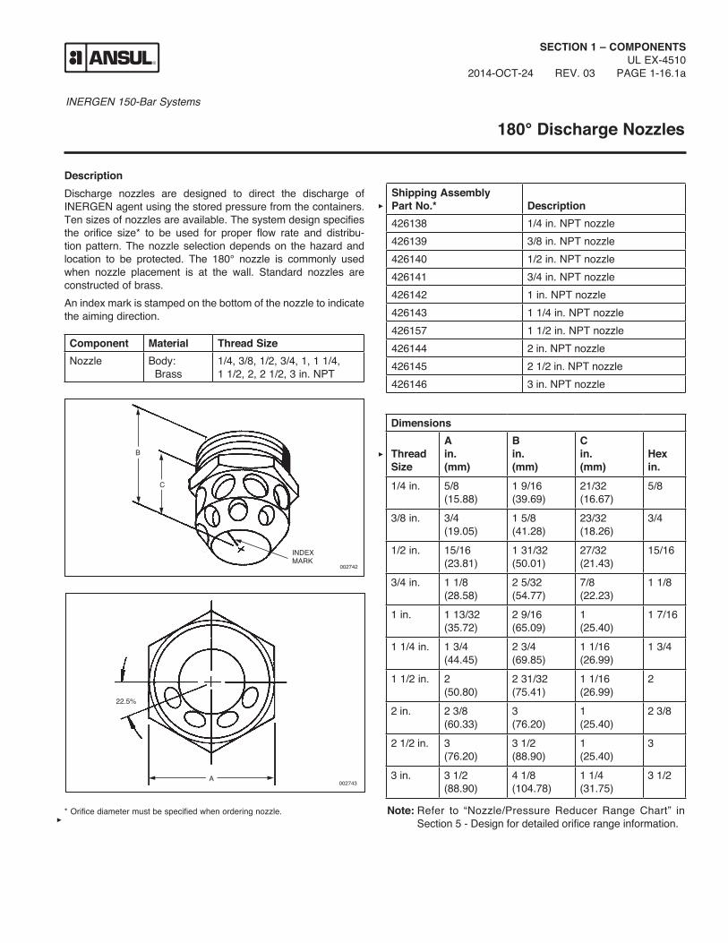
DescriptionDischarge nozzles are designed to direct the discharge of INERGEN agent using the stored pressure from the containers. Ten sizes of nozzles are available. The system design specifies the orifice size* to be used for proper flow rate and distribu-tion pattern. The nozzle selection depends on the hazard and location to be protected. The 180° nozzle is commonly used when nozzle placement is at the wall. Standard nozzles are constructed of brass.An index mark is stamped on the bottom of the nozzle to indicate the aiming direction.
SECTION 1 – COMPONENTSUL EX-4510
2014-OCT-24 REV. 03 PAGE 1-16.1a
180° Discharge Nozzles
Shipping AssemblyPart No.*
Description
426138 1/4 in. NPT nozzle426139 3/8 in. NPT nozzle426140 1/2 in. NPT nozzle426141 3/4 in. NPT nozzle426142 1 in. NPT nozzle426143 1 1/4 in. NPT nozzle426157 1 1/2 in. NPT nozzle426144 2 in. NPT nozzle426145 2 1/2 in. NPT nozzle426146 3 in. NPT nozzle
Note: Refer to “Nozzle/Pressure Reducer Range Chart” in Section 5 - Design for detailed orifice range information.
Dimensions Thread Size
Ain.(mm)
Bin.(mm)
Cin.(mm)
Hex in.
1/4 in. 5/8(15.88)
1 9/16(39.69)
21/32(16.67)
5/8
3/8 in. 3/4(19.05)
1 5/8(41.28)
23/32(18.26)
3/4
1/2 in. 15/16(23.81)
1 31/32(50.01)
27/32(21.43)
15/16
3/4 in. 1 1/8(28.58)
2 5/32(54.77)
7/8(22.23)
1 1/8
1 in. 1 13/32(35.72)
2 9/16(65.09)
1(25.40)
1 7/16
1 1/4 in. 1 3/4(44.45)
2 3/4(69.85)
1 1/16(26.99)
1 3/4
1 1/2 in. 2(50.80)
2 31/32(75.41)
1 1/16(26.99)
2
2 in. 2 3/8(60.33)
3(76.20)
1(25.40)
2 3/8
2 1/2 in. 3(76.20)
3 1/2(88.90)
1(25.40)
3
3 in. 3 1/2(88.90)
4 1/8(104.78)
1 1/4(31.75)
3 1/2
* Orifice diameter must be specified when ordering nozzle.
002743
22.5%
A
Component Material Thread SizeNozzle Body:
Brass1/4, 3/8, 1/2, 3/4, 1, 1 1/4, 1 1/2, 2, 2 1/2, 3 in. NPT
C
002742
B
INDEXMARK

INERGEN 150-Bar Systems
NOTES:
SECTION 1 – COMPONENTSUL EX-4510PAGE 1-16.1b REV. 0 2014-OCT-24

INERGEN 150-Bar Systems
SECTION 1 – COMPONENTSUL EX-4510
2014-OCT-24 REV. 03 PAGE 1-16.2a
Nozzle Deflector Shield
DescriptionThe INERGEN system nozzle deflector shield is used to control the pattern of the discharge of the INERGEN agent. The deflec-tor shield helps keep the agent discharge away from false ceiling tiles and fragile light fixtures, avoiding damage to them.Note: The nozzle deflector shields are only for use with the 360° discharge nozzles.The deflector shields are constructed of steel and painted with a cameo cream colored paint. They are available in five sizes.
Shipping Assembly Part No.
A Inlet NPT
B Length of Coupling
in. (mm)
C Overall Length
in. (mm)
D Deflector O.D.
in. (mm)
E Coupling O.D.
in. (mm)417708 1/2 in. 1 7/8 (48) 3 (76) 3 3/8 (86) 1 1/8 (29)417711 3/4 in. 2 (51) 3 1/4 (83) 3 3/8 (86) 1 3/8 (35)417714 1 in. 2 3/8 (60) 3 13/16 (97) 4 7/8 (124) 1 3/4 (44)417717 1 1/4 in. 2 5/8 (67) 4 3/16 (106) 4 7/8 (124) 2 1/4 (57)417720 1 1/2 in. 3 1/8 (79) 4 29/32 (125) 5 21/32 (14) 2 1/2 (64)
Component Material ApprovalsNozzle Deflector Shield
Steel UL Listed (EX-4510); Listed for use with FM Approved systems
Note: There are no deflector shields available for the 2 in., 2 1/2 in., or 3 in. models.
D
B
A
C
E
003651

INERGEN 150-Bar Systems
NOTES:
SECTION 1 – COMPONENTSUL EX-4510PAGE 1-16.2b REV. 0 2014-OCT-24
INERGEN 150-Bar Systems
SECTION 1 – COMPONENTSUL EX-4510
2014-OCT-24 REV. 10 PAGE 1-17a
Container Bracketing
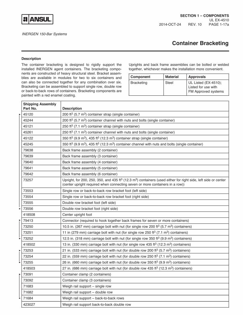
DescriptionThe container bracketing is designed to rigidly support the installed INERGEN agent containers. The bracketing compo-nents are constructed of heavy structural steel. Bracket assem-blies are available in modules for two to six containers and can also be connected together for any combination over six. Bracketing can be assembled to support single row, double row or back-to-back rows of containers. Bracketing components are painted with a red enamel coating.
Uprights and back frame assemblies can be bolted or welded together, whichever makes the installation more convenient.
Component Material ApprovalsBracketing Steel UL Listed (EX-4510);
Listed for use with FM Approved systems
Shipping Assembly Part No.
Description
45120 200 ft3 (5.7 m3) container strap (single container)45244 200 ft3 (5.7 m3) container channel with nuts and bolts (single container)45121 250 ft3 (7.1 m3) container strap (single container)45261 250 ft3 (7.1 m3) container channel with nuts and bolts (single container)45122 350 ft3 (9.9 m3), 435 ft3 (12.3 m3) container strap (single container)45245 350 ft3 (9.9 m3), 435 ft3 (12.3 m3) container channel with nuts and bolts (single container)79638 Back frame assembly (2 container)79639 Back frame assembly (3 container)79640 Back frame assembly (4 container)79641 Back frame assembly (5 container)79642 Back frame assembly (6 container)73257 Upright, for 200, 250, 350, and 435 ft3 (12.3 m3) containers (used either for right side, left side or center
(center upright required when connecting seven or more containers in a row))73553 Single row or back-to-back row bracket foot (left side)73554 Single row or back-to-back row bracket foot (right side)73555 Double row bracket foot (left side)73556 Double row bracket foot (right side)418508 Center upright foot79413 Connector (required to hook together back frames for seven or more containers)73250 10.5 in. (267 mm) carriage bolt with nut (for single row 200 ft3 (5.7 m3) containers)73251 11 in (279 mm) carriage bolt with nut (for single row 250 ft3 (7.1 m3) containers)73252 12.5 in. (318 mm) carriage bolt with nut (for single row 350 ft3 (9.9 m3) containers)418502 13 in. (330 mm) carriage bolt with nut (for single row 435 ft3 (12.3 m3) containers)73253 21 in. (533 mm) carriage bolt with nut (for double row 200 ft3 (5.7 m3) containers)73254 22 in. (559 mm) carriage bolt with nut (for double row 250 ft3 (7.1 m3) containers)73255 26 in. (660 mm) carriage bolt with nut (for double row 350 ft3 (9.9 m3) containers)418503 27 in. (686 mm) carriage bolt with nut (for double row 435 ft3 (12.3 m3) containers)73091 Container clamp (2 containers)73092 Container clamp (3 containers)71683 Weigh rail support – single row71682 Weigh rail support – double row71684 Weigh rail support – back-to-back rows423027 Weigh rail support back-to-back double row

INERGEN 150-Bar SystemsSECTION 1 – COMPONENTSUL EX-4510PAGE 1-17b REV. 10 2014-OCT-24
Multi-Container Single Container
UPRIGHT
BACK FRAME
CONTAINER CLAMP
CARRIAGE BOLTWITH NUT
RIGHTBRACKET FOOT
LEFTBRACKET FOOT
CHANNEL
002200
CLAMP
WEIGH RAIL SUPPORT

INERGEN 150-Bar Systems
SECTION 1 – COMPONENTSUL EX-4510
2014-OCT-24 REV. 06 PAGE 1-18a
Pressure Switch – 3PDT
DescriptionThe pressure switch is operated by INERGEN agent pressure when the system is discharged. The pressure switch can be used to open or close electrical circuits to shut down equipment (single or 3-phase) or turn on lights or alarms. The housing is constructed of 16 ga. steel, painted red, and is rated IP65 for dust and water ingress. The 3/8 in. NPT brass pressure inlet is used to connect the pressure switch to the suppression system.Minimum operating pressure is 50 psi (3.5 bar).
008979
6.0 IN.(152 mm)
4.45 IN.(113 mm)
2.75 IN.(70 mm)
5.25 IN.(133 mm)
0089783.83 IN.(97 mm)
4.45 IN.(113 mm)
4.51 IN.(115 mm)
Component Material Thread Size/Type Electrical Rating Approvals
Pressure Switch – 3PDT
Switch: Nickel-plated BrassHousing/Cover: C.R. 16 ga. steelPlunger: Stainless SteelPressure Port: C37700 Brass
Conduit Inlets: 3/4 in. and 1/2 in.Pressure Inlet: 3/8 in. NPT Female
10A, 250 VAC15A, 125 VAC3/4 HP, 250 VAC1-, 2-, and 3-phase
UL Listed (EX-4510); Listed for use with FM Approved systems
Shipping Assembly Part No.
Description
437900 Pressure switch – 3PDT

INERGEN 150-Bar Systems
NOTES:
SECTION 1 – COMPONENTSUL EX-4510PAGE 1-18b REV. 0 2014-OCT-24

INERGEN 150-Bar Systems
Pressure Switch DPDT – Explosion-Proof
SECTION 1 – COMPONENTSUL EX-4510
2014-OCT-24 REV. 06 PAGE 1-18.1a
DescriptionThe pressure switch is operated by the INERGEN agent pres-sure when the system is discharged. The pressure switch can be used to open or close electrical circuits to either shut down equipment or turn on lights or alarms. The double pole, double throw (DPDT) pressure switch is constructed with an explosion-proof housing suitable for hazardous environments. A 1/4 in. NPT pressure inlet is used to connect the 1/4 in. pipe from the INERGEN system.
The pressure switch can be installed either before or after the pressure reducer in the distribution piping.Minimum operating pressure is 50 PSI (3.5 bar)
Note: Suitable for hazardous locations, Class I, Division I, Groups C, D, and Class II, Division I, Groups E, F, G.
Shipping Assembly Part No.
Description
43241 Pressure switch – DPDT
000455
1/4 IN. PIPE CONNECTION TO INERGEN SYSTEM
1/4 IN. UNION
3/8 IN. X 1/4 IN. BUSHING
NAMEPLATE
2 11/32 IN. MOUNTING HOLES
7 7/8 IN.(200 mm)
6 1/2 IN.(165 mm)
5 3/16 IN.(147 mm)
5 1/8 IN.(130 mm)
3 9/16 IN.(90 mm)
2 5/8 IN.(66 mm)
000454
5 5/8 IN.(142 mm)
3/4 IN. CONDUIT OUTLET
3/4 IN. CONDUIT OUTLET
Component Material Thread Size/Type Electrical Rating ApprovalsPressure Switch DPDT
Housing: Malleable Iron
Conduit Inlet: 3/4 in. NPT Female Pressure Inlet: 1/4 in. NPT Female
10A - 125 VAC5A - 250 VAC
UL Listed (EX-4510); Listed for use with FM Approved systems

INERGEN 150-Bar Systems
NOTES:
SECTION 1 – COMPONENTSUL EX-4510PAGE 1-18.1b REV. 0 2014-OCT-24

INERGEN 150-Bar Systems
SECTION 1 – COMPONENTSUL EX-4510
2014-OCT-24 REV. 04 PAGE 1-19a
Pressure Trip
DescriptionThe pressure trip is connected to the actuation or discharge line of an INERGEN system. By either pneumatic or manual actu-ation, the pressure trip can release spring or weight powered devices to close doors and windows, open fuel dump valves, close fire dampers or close fuel supply valves. The pressure trip is constructed of brass with two 1/4 in. NPT fittings for connec-tion to discharge or actuation lines. The link on the pressure switch is released either pneumatically, by agent discharge pres-sure; or manually, by use of the pull ring. The link then releases the device which performs the auxiliary functions.Note: Operating pressure must be a minimum of 75 psi (5.2 bar)
with a maximum load of 70 lb (31.8 kg).
Shipping Assembly Part No.
Description
5156 Pressure trip
Component
Material
Thread Size/Type
Approvals
Pressure Trip
Brass 1/4 in. NPT Female
UL Listed (EX-4510); Listed for use with FM Approved systems
3 3/4 IN.(95 mm)
1/4 IN. NPT
3 IN.(76 mm)
000452

INERGEN 150-Bar Systems
NOTES:
SECTION 1 – COMPONENTSUL EX-4510PAGE 1-19b REV. 0 2014-OCT-24

INERGEN 150-Bar Systems
Pressure Test Assembly
SECTION 1 – COMPONENTSUL EX-4510
2014-OCT-24 REV. 04 PAGE 1-20a
DescriptionThe Pressure Test Assembly (Part No. 416753 for CV-90 valves and Part No. 423923 for CV-98 valves) is required to properly perform the semi-annual pressure check per NFPA 2001. The pressure test assembly consists of a calibrated gauge, adaptor, and handwheel. The assembly is attached to the fill port of the INERGEN valve. As the handwheel is turned in, the fill port is opened and the pressure is read on the gauge. After verifying the pressure in the container, the handwheel is turned out, closing the fill port, and the assembly can be removed.
Two pressure tester convertors are also available. These convertors allow a CV-90 pressure test assembly to be used on a CV-98 valve and also a CV-98 pressure test assembly to be used on a CV-90 valve.
Shipping Assembly Part No.
Description
416753 Pressure Test Assembly – CV-90423923 Pressure Test Assembly – CV-98423657 Adaptor Convertor (converts CV-90
pressure tester to CV-98 valve)426181 Adaptor Convertor (converts CV-98
pressure tester to CV-90 valve)70386 Washer
416753
002256
423923
003686
Component Material ApprovalsHandwheel Cast Zinc Alloy UL Listed (EX-4510);
Listed for use with FM Approved systems
Body BrassAdaptor BrassGauge Stainless Steel
Case Laminated Safety Glass Lens

INERGEN 150-Bar Systems
NOTES:
SECTION 1 – COMPONENTSUL EX-4510PAGE 1-20b REV. 0 2014-OCT-24

INERGEN 150-Bar Systems
Pressure-Operated Siren
SECTION 1 – COMPONENTSUL EX-4510
2014-OCT-24 REV. 02 PAGE 1-20.1a
DescriptionThe pressure-operated siren is used to warn personnel of a system discharge. The siren operates upon pilot container activation and continues to sound through most of the discharge time. A pipe hanger or bracket must be installed within 1 ft (0.3 m) of the siren.
The design requirements are as follows:• Maximum Pipe Length: – 240 ft (73.2 m) of 3/4 in. Schedule 40 pipe – 430 ft (131.1 m) of 1/2 in. Schedule 40 pipe – 675 ft (205.7 m) of 3/8 in. Schedule 40 pipe• Maximum Sirens: 5• Maximum Elbows: 30• Flow Rate: 144 ft3/min. (4.1 m3/min.)• If siren is not located in hazard area, include agent flow and
quantity through siren in system design
Note: The pressure-operated siren is not recommended for use in data center applications.
1/4 IN.NPT INLET
6.25 IN.(159 mm)
008806
0.34 IN. (9 mm) DIA. HOLE (2)
5.25 IN.(133 mm)
5.60 IN.(142 mm)
3.42 IN.(87 mm)
Component Material ApprovalsSiren Body: Brass
Grille: SteelScreen: Stainless
Steel
UL Listed (EX-4510); Listed for use with FM Approved systems
Shipping Assembly Part No.
Description
437616 Pressure-operated siren

INERGEN 150-Bar Systems
NOTES:
SECTION 1 – COMPONENTSUL EX-4510PAGE 1-20.1b REV. 0 2014-OCT-24

INERGEN 150-Bar Systems
SECTION 1 – COMPONENTSUL EX-4510
2014-OCT-24 REV. 01 PAGE 1-20.2a
Time Delay Assembly
DescriptionThe time delay is available in delay settings of 28 or 55 seconds. The delay uses INERGEN agent to power the factory-set delay mechanism. A manual release is incorporated on the time delay valve to allow instant delay override.
Note: Refer to Section 7 – Testing and Placing in Service for time delay testing instructions.
008608
008608
8 1/2 IN.(216 mm)
7 3/4 IN.(197 mm)
2 3/4 IN.(70 mm)
7 1/4 IN.(184 mm)
9 7/8 IN.(251 mm)
7 5/16 IN.(186 mm)
15 1/2 IN.(394 mm)
12 7/8 IN.(327 mm)
Shipping Assembly Part No.
Description
440966 28 second time delay440965 55 second time delay

INERGEN 150-Bar Systems
NOTES:
SECTION 1 – COMPONENTSUL EX-4510PAGE 1-20.2b REV. 0 2014-OCT-24
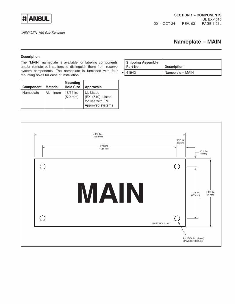
INERGEN 150-Bar Systems
DescriptionThe ‘‘MAIN’’ nameplate is available for labeling components and/or remote pull stations to distinguish them from reserve system components. The nameplate is furnished with four mounting holes for ease of installation.
SECTION 1 – COMPONENTSUL EX-4510
2014-OCT-24 REV. 03 PAGE 1-21a
Nameplate – MAIN
MAIN
5 1/2 IN.(139 mm)
4 7/8 IN.(124 mm)
1 7/8 IN.(47 mm)
2 1/2 IN.(64 mm)
5/16 IN.(8 mm)
5/16 IN.(8 mm)
PART NO. 41942
4 – 13/64 IN. (5 mm)DIAMETER HOLES
Shipping Assembly Part No.
Description
41942 Nameplate – MAIN
Component
Material
Mounting Hole Size
Approvals
Nameplate Aluminum 13/64 in. (5.2 mm)
UL Listed (EX-4510); Listed for use with FM Approved systems

INERGEN 150-Bar Systems
NOTES:
SECTION 1 – COMPONENTSUL EX-4510PAGE 1-21b REV. 0 2014-OCT-24
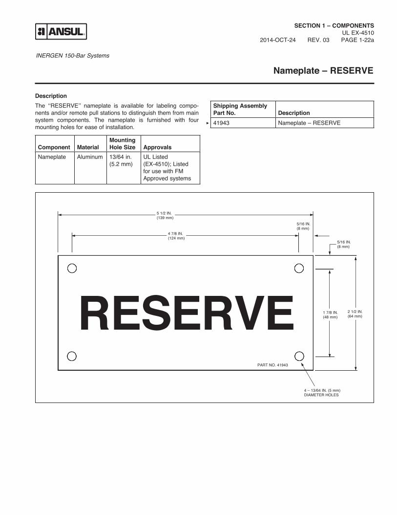
INERGEN 150-Bar Systems
Nameplate – RESERVE
SECTION 1 – COMPONENTSUL EX-4510
2014-OCT-24 REV. 03 PAGE 1-22a
DescriptionThe ‘‘RESERVE’’ nameplate is available for labeling compo-nents and/or remote pull stations to distinguish them from main system components. The nameplate is furnished with four mounting holes for ease of installation.
RESERVE
5 1/2 IN.(139 mm)
4 7/8 IN.(124 mm)
1 7/8 IN.(48 mm)
2 1/2 IN.(64 mm)
5/16 IN.(8 mm)
5/16 IN.(8 mm)
PART NO. 41943
4 – 13/64 IN. (5 mm)DIAMETER HOLES
Shipping Assembly Part No.
Description
41943 Nameplate – RESERVE
Component
Material
Mounting Hole Size
Approvals
Nameplate Aluminum 13/64 in. (5.2 mm)
UL Listed (EX-4510); Listed for use with FM Approved systems

INERGEN 150-Bar Systems
NOTES:
SECTION 1 – COMPONENTSUL EX-4510PAGE 1-22b REV. 0 2014-OCT-24

INERGEN 150-Bar Systems
Warning Plate – Inside Room With Alarm
SECTION 1 – COMPONENTSUL EX-4510
2012-FEB-01 REV. 02 PAGE 1-23a
DescriptionThe warning plate is available for mounting inside the hazard area to warn the personnel to vacate the hazard area when the alarm sounds. The warning plate is furnished with four mounting holes for ease of installation. The plate is constructed of alumi-num.
Shipping Assembly Part No.
Description
416265 Warning Plate – inside room with alarm
Component
Material
Mounting Hole Size
Approvals
Warning Plate
Aluminum 1/4 in. (6.4 mm)
UL Listed (EX-4510); Listed for use with FM Approved systems
WHEN ALARM SOUNDSVACATE AT ONCEINERGEN® AGENTBEING RELEASED
12 IN. (305 mm)
7 IN.(178 mm)
LABEL NO. 416265
AGENTFIRE EXTINGUISHING
002746

INERGEN 150-Bar Systems
NOTES:
SECTION 1 – COMPONENTSUL EX-4510PAGE 1-23b REV. 0 2014-OCT-24

INERGEN 150-Bar Systems
Warning Plate – Outside Room Without Alarm
SECTION 1 – COMPONENTSUL EX-4510
2012-FEB-01 REV. 03 PAGE 1-24a
DescriptionThe warning plate is available for mounting outside the hazard area to warn the personnel that the space is protected by an INERGEN system and no one should enter after a discharge without being properly protected. The warning plate is furnished with four mounting holes for ease of installation.
Shipping Assembly Part No.
Description
416266 Warning Plate – outside room
Component
Material
Mounting Hole Size
Approvals
Warning Plate
Aluminum 7/32 in. (5.6 mm)
UL Listed (EX-4510); Listed for use with FM Approved systems
AGENTFIRE EXTINGUISHING
WARNINGTHIS SPACE IS PROTECTED BY AN INERGEN® FIRE SUPPRESSION SYSTEM.WHEN SYSTEM IS DISCHARGED AS A RESULT OF FIRE, CAUTION MUST BE TAKEN TO AVOID EXPOSURE TO PRODUCTS OF COMBUSTION.DO NOT ENTER WITHOUT APPROVED SELF-CONTAINED BREATHING APPARATUS OR UNTIL VENTILATION HAS BEEN OPER-ATED FOR AT LEAST 15 MINUTES.
8 IN. (203 mm)
7 IN.(178 mm)
LABEL NO. 416266
002747

INERGEN 150-Bar Systems
NOTES:
SECTION 1 – COMPONENTSUL EX-4510PAGE 1-24b REV. 0 2014-OCT-24