Lateral-torsional buckling of steel girders with trapezoidally

Inelastic Lateral-Torsional Buckling Strength Validation
for Non-Principal Axis Bending Using Numerical Methods
S. Wang
advised by B.W. Schafer and R.S. Glauz
January 2020
COLD-FORMED STEEL RESEARCH CONSORTIUM
REPORT SERIES CFSRC R-2020-01

Inelastic Lateral-Torsional Buckling Strength Validation for Non-Principal Axis Bending Using Numerical Methods
1
CFSRC Information: The Cold-Formed Steel Research Consortium (CFSRC) is a multi-institute consortium of university researchers dedicated to providing world-leading research that enables structural engineers and manufacturers to realize the full potential of structures utilizing cold-formed steel. More information can be found at www.cfsrc.org. All CFSRC reports are hosted permanently by the Johns Hopkins University library in the DSpace collection:
https://jscholarship.library.jhu.edu/handle/1774.2/40427. American Iron and Steel Institute Acknowledgment: This report was prepared in part based on a fellowship provided to the first author from the American Iron and Steel Institute. Any opinions, findings, and conclusions or recommendations expressed in this publication are those of the author(s) and do not necessarily reflect the views of the National Science Foundation.
Table of Contents
Abstract ............................................................................................................................................ 3
1 Introduction ............................................................................................................................. 4
2 Selected Cross-sections ........................................................................................................... 7
3 Cross-section Properties .......................................................................................................... 8
4 Elastic Lateral-torsional Buckling Calculations .................................................................... 10
5 Shell FE Collapse Analysis ................................................................................................... 11
5.1 Model setup .................................................................................................................. 11
5.2 Typical Result .............................................................................................................. 12
5.3 Studied Cases ............................................................................................................... 16
5.4 Full Results ................................................................................................................... 18
5.5 Imperfection sensitivity ............................................................................................... 30
6 Studied Design Methods ........................................................................................................ 33
6.1 Method 1: AISI S100-16 Approximate Approach .................................................... 33
6.2 Method 2: AISI S100-16 Interaction Approach ....................................................... 34
6.3 Method 3: Direct Bi-axial Bending Approach .......................................................... 36
6.4 Sample Calculation for 6ZS2.25×105 Cross-section ................................................. 37
6.4.1 Method 1 .................................................................................................................. 37
6.4.2 Method 2 .................................................................................................................. 38
6.4.3 Method 3 .................................................................................................................. 39
7 Evaluation of Design Methods .............................................................................................. 40
8 Conclusions ........................................................................................................................... 52
9 References ............................................................................................................................. 53
10 Appendices ............................................................................................................................ 54
10.1 Completed results for plastic moment ....................................................................... 54
10.2 Completed results for numerical analysis. ................................................................ 57
Inelastic Lateral-Torsional Buckling Strength Validation for Non-Principal Axis Bending Using Numerical Methods
3
Abstract
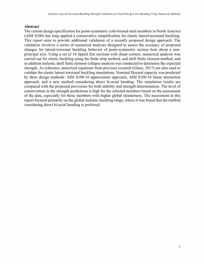
The current design specification for point-symmetric cold-formed steel members in North America (AISI S100) has long applied a conservative simplification for elastic lateral-torsional buckling. This report aims to provide additional validation of a recently proposed design approach. The validation involves a series of numerical analyses designed to assess the accuracy of proposed changes for lateral-torsional buckling behavior of point-symmetric section bent about a non-principal axis. Using a set of 14 lipped Zee sections with sharp corners, numerical analysis was carried out for elastic buckling using the finite strip method, and shell finite element method, and in addition inelastic shell finite element collapse analysis was conducted to determine the expected strength. As reference, analytical equations from previous research (Glauz, 2017) are also used to validate the elastic lateral-torsional buckling simulations. Nominal flexural capacity was predicted by three design methods: AISI S100-16 approximate approach, AISI S100-16 linear interaction approach, and a new method considering direct bi-axial bending. The simulation results are compared with the proposed provisions for both stability and strength determination. The level of conservatism in the strength predictions is high for the selected members based on the assessment of the data, especially for those members with higher global slenderness. The assessment in this report focused primarily on the global inelastic buckling range, where it was found that the method considering direct bi-axial bending is preferred.

S. Wang & B.W. Schafer & R.S. Glauz
4
1 Introduction
This project was conducted as part of a fellowship supported by the American Iron and Steel Institute (AISI). The project fellowship application well describes the current state of the art in lateral-torsional buckling of general open cold-formed steel cross-sections when loaded about non-principal axes and is directly quoted here to provide an efficient introduction:
“Current AISI provisions for lateral-torsional buckling of non-symmetric cold-formed steel members can be overly conservative. The Specification [AISI S100] has long taken a simplistic approach to lateral-torsional buckling provisions for non-symmetric members – and these provisions are particularly problematic when the bracing and the principal axes of the section do not align. Such bracing conditions are common since the bracing tends to follow the overall structural layout (struts or straps from frame/roof lines, rack uprights and beams, etc.) while the member section has principal axes that are inclined to the structural layout. Non-symmetric members can potentially serve as efficient purlins, girts, joists, rack uprights, etc. as they allow the section to be optimized for shipping, unequal bending demands, and other unique conditions. The future application of efficient cross-sections in cold-formed steel structural systems relies on accurate provisions for predicting the strength in these conditions. AISI ballot S17-438A introduced provisions for determining the lateral-torsional elastic buckling stress for non-symmetric sections bending about non-principal axes. This ballot received a high response and approval rate, but one negative vote prevented the ballot from passing. Although the determination of elastic buckling stress was well supported, the remainder of the bending strength provisions in the Specification were insufficient for non-principal axes. A proposed method of handling biaxial bending strength was presented to members of Subcommittee 24 on Member Design in July 2017, with validation against a small set of physical test data. The objective of this project is to provide additional validation of the proposed design approach. Since the available set of physical test data is limited, this project will involve numerical analysis for validation. The sections and analysis parameters used in this study will be strategically chosen to reflect representative and sufficient cases to validate the method, but with the objective of reducing the analysis effort. Upon completion of this work, a revised ballot S17-438B will be prepared for approval by Subcommittee 24. ”

Inelastic Lateral-Torsional Buckling Strength Validation for Non-Principal Axis Bending Using Numerical Methods
5
Non-symmetric members can potentially serve as efficient purlins, girts, joists, rack uprights, etc. Unlike conventional singly-symmetric cold-formed steel members, the support layout and the principal axes do not align for such members. For example, the common Zee-shaped sections have principal axes inclined from the web and flange as shown in Fig. 1. As a result of the location of the principal axis common gravity loading (for example in the -Y direction of Fig.1) causes bending about both principal axes - which leads to difficulty in determining the critical elastic lateral-torsional buckling stress. Analytical formula for the elastic lateral-torsional (global) buckling for bending about any inclined axis from the major principal axis has recently been developed by Glauz (2017) and serves as motivation for this study. In addition to the geometric (X-Y) and principal (1-2) axes Fig. 1 depicts another set of arbitrary axes (a-b) which are an angle θ from the principal major axis, and an angle β from geometric axis. In the work herein, we will consider bending about the arbitrary axis “a” and the resulting global elastic buckling and strength. As depicted in Fig. 2 and Fig. 3 bending about axis “a” may result from directly applied loads (Wa) or moments (Ma) – regardless such actions may be decomposed back into the principal axes (1 and 2) or considered directly in the axes of bending (a). Considering the classic case of end moment, Ma, may be expressed as stress at the end of the member as shown in Fig. 4. This report considers the elastic bucking, inelastic buckling, and ultimate strength of typical Zee-shaped cold-formed steel members under the end stress of Fig. 4 developed from end moment Ma. As discussed herein, members and details are selected to focus on global lateral-torsional buckling, not local or distortional buckling.

S. Wang & B.W. Schafer & R.S. Glauz
6
Figure 1. Geometric (X-Y), principal (1-2), and arbitrary (a-b) coordinate axes.
Figure 2. Decomposition of force (Wa) and end moment (Ma) for θ =10°.
Figure 3. Example member loading for force and applied end moments at θ =10°.
Figure 4. Equivalent end stress for applied end moment example at θ =10°.
Y
2
a
Ɵ+
b
x
1
β+
a T
b
1
!"
!#
!$ 1
a
b
2
%$
%#
%"
Ɵ=10°
2
b Transitio
a rans
!"
#"
#"
b Transitio
a rans
a ransit
ENA Tran
Compression Transition angle: twist angle=theta
Tension
Compression Transition angle: twist angle=theta
Tension

Inelastic Lateral-Torsional Buckling Strength Validation for Non-Principal Axis Bending Using Numerical Methods
7
2 Selected Cross-sections
Fourteen lipped Zee sections are selected based on Glauz (2017). AISI-D100 is used as the reference to identify section dimensions for the studied members. A centerline model is used for calculating the torsional properties. In addition, it is assumed that the corners are sharp. The reason for using the sharp corner in the analytical approximations and models is to avoid additional disagreement between analytical solutions which require torsion property, Cw, (and traditionally use sharp corners) and numerical solutions which do not require sharp corners and thus focus any differences on behavior – not the calculation method. CUFSM is used for generating the section models and the section properties are verified with the AISI-D100 cross-section tables. The section dimensions are shown in Table 1.
Table 1. Sharp corner Zee section dimensions for CUFSM input.
ID
dimensions
D B t d & R Area
in. in. in. in. deg in. in.^2
12ZS3.25×105 12.000 3.250 0.105 0.990 50 0 2.118
12ZS2.75×105 12.000 2.750 0.105 0.990 50 0 2.013
12ZS2.25×105 12.000 2.250 0.105 0.990 50 0 1.908
10ZS3.25×105 10.000 3.250 0.105 0.990 50 0 1.908
10ZS2.75×105 10.000 2.750 0.105 0.990 50 0 1.803
10ZS2.25×105 10.000 2.250 0.105 0.990 50 0 1.698
9ZS2.25×105 9.000 2.250 0.105 0.990 50 0 1.593
8ZS3.25×105 8.000 3.250 0.105 0.990 50 0 1.698
8ZS2.75×105 8.000 2.750 0.105 0.990 50 0 1.593
8ZS2.25×105 8.000 2.250 0.105 0.990 50 0 1.488
7ZS2.25×105 7.000 2.250 0.105 0.990 50 0 1.383
6ZS2.25×105 6.000 2.250 0.105 0.990 50 0 1.278
4ZS2.25×70 4.000 2.250 0.070 0.930 50 0 0.711
3.5ZS1.5×70 3.500 1.500 0.070 0.680 50 0 0.536

S. Wang & B.W. Schafer & R.S. Glauz
8
3 Cross-section Properties
To insure that the selected cross-sections were being transferred to software correctly and to understand the impact of different modeling assumptions cross-section properties for the selected Z-sections were calculated by hand, and in models created with the programs CFS (version 11) and CUFSM (version 5.03).
Table 2. Sharp corner Zee section properties from CUFSM.
ID
Properties of Full Section
Axis x-x Axis y-y Ixy Ix2 Iy2 rmin α J Cw
Ix Sx rx Iy Sy ry
in.^4 in.^3 in. in.^4 in.^3 in. in.^4 in.^4 in.^4 in. deg in.^4 in.^6
12ZS3.25×105 44.614 7.436 4.589 4.703 1.210 1.490 10.219 2.239 47.078 1.028 76.442 0.008 122.563
12ZS2.75×105 40.900 6.817 4.507 3.148 0.930 1.251 7.828 1.589 42.459 0.888 78.738 0.007 85.085
12ZS2.25×105 37.186 6.198 4.415 1.975 0.684 1.017 5.750 1.060 38.101 0.745 80.957 0.007 55.513
10ZS3.25×105 29.046 5.809 3.902 4.703 1.210 1.570 8.456 2.054 31.695 1.038 72.606 0.007 81.836
10ZS2.75×105 26.476 5.295 3.832 3.148 0.930 1.321 6.473 1.472 28.151 0.904 75.486 0.007 57.000
10ZS2.25×105 23.905 4.781 3.752 1.975 0.684 1.079 4.750 0.990 24.890 0.764 78.289 0.006 37.333
9ZS2.25×105 18.565 4.126 3.414 1.975 0.684 1.113 4.251 0.950 19.591 0.772 76.434 0.006 29.668
8ZS3.25×105 17.294 4.323 3.191 4.703 1.210 1.664 6.692 1.811 20.186 1.033 66.625 0.006 49.874
8ZS2.75×105 15.658 3.914 3.135 3.148 0.930 1.406 5.118 1.321 17.485 0.911 70.354 0.006 34.870
8ZS2.25×105 14.021 3.505 3.070 1.975 0.684 1.152 3.751 0.903 15.093 0.779 74.044 0.005 22.942
7ZS2.25×105 10.222 2.920 2.719 1.975 0.684 1.195 3.251 0.848 11.349 0.783 70.872 0.005 17.143
6ZS2.25×105 7.114 2.371 2.359 1.975 0.684 1.243 2.752 0.780 8.309 0.781 66.518 0.005 12.259
4ZS2.25×70 1.882 0.941 1.627 1.294 0.454 1.349 1.175 0.376 2.799 0.728 52.012 0.001 3.383
3.5ZS1.5×70 1.032 0.590 1.388 0.400 0.206 0.864 0.476 0.145 1.287 0.520 61.799 0.001 0.830
Table 3. Percent difference between CUFSM model and D-100 tables.
ID`
Properties of Full Section
Axis x-x Axis y-y Ixy Ix2 Iy2 rmin α J Cw
Ix Sx rx Iy Sy ry
in.^4 in.^3 in. in.^4 in.^3 in. in.^4 in.^4 in.^4 in. deg in.^4 in.^6
12ZS3.25×105 2.09% 2.00% 0.43% 0.70% -0.81% 0.01% 0.19% 2.69% 1.90% 0.79% 0.19% 1.22% -0.36%
12ZS2.75×105 2.25% 2.20% 0.39% 0.58% -0.89% 0.04% 0.62% 2.53% 2.06% 0.62% 0.18% 1.20% -0.02%
12ZS2.25×105 2.44% 2.44% 0.56% 0.78% -1.11% -0.25% 0.69% 2.92% 2.42% 0.59% 0.19% 1.33% 0.02%
10ZS3.25×105 2.27% 2.09% 0.30% 0.70% -0.81% -0.64% 0.54% 2.71% 1.91% 0.73% 0.28% 1.33% 0.04%
10ZS2.75×105 2.22% 2.42% 0.57% 0.58% -0.89% -0.65% 0.51% 2.96% 2.00% 0.74% 0.38% 1.32% 0.00%
10ZS2.25×105 2.60% 2.60% 0.59% 0.78% -1.11% -0.14% 0.64% 2.96% 2.43% 0.76% 0.24% 1.47% 0.09%
9ZS2.25×105 2.57% 2.63% 0.70% 0.78% -1.11% -0.58% 0.72% 3.21% 2.57% 0.79% 0.31% 1.64% -0.11%
8ZS3.25×105 2.33% 2.21% 0.35% 0.70% -0.81% -0.35% 0.48% 3.46% 1.95% 1.23% 0.49% 1.47% -0.05%
8ZS2.75×105 2.34% 2.47% 0.48% 0.58% -0.89% -0.30% 0.55% 3.20% 2.25% 0.95% 0.51% 1.64% -0.09%
8ZS2.25×105 3.10% 2.80% 0.64% 0.78% -1.11% -0.68% 0.56% 3.52% 2.67% 0.89% 0.47% 1.65% 0.18%
7ZS2.25×105 3.04% 3.20% 0.69% 0.78% -1.11% -0.41% 0.66% 4.00% 2.25% 1.14% 0.53% 1.86% 0.25%

Inelastic Lateral-Torsional Buckling Strength Validation for Non-Principal Axis Bending Using Numerical Methods
9
6ZS2.25×105 3.24% 3.09% 0.39% 0.78% -1.11% -0.55% 0.79% 4.67% 2.45% 1.31% 0.79% 1.89% -0.33%
4ZS2.25×70 3.38% 3.38% 0.43% 1.12% -0.55% -0.78% 0.46% 6.00% 1.80% 1.90% 0.99% 1.84% 0.09%
3.5ZS1.5×70 4.79% 4.77% 0.57% 0.99% -0.74% -0.92% 0.82% 8.04% 2.99% 2.32% 1.31% 2.96% -0.01%
Table 2 shows the cross-section properties for Zees from CUFSM, and Table 3 shows the comparison from software results to the AISI-D100 reference. Larger differences exist for other properties (I, etc.) because D100-17 uses rounded corners for them (note if round corner models are created in CUFSM and CFS agreement is nearly exact – but then Cw agreement is poor). Small differences exist for Cw because D100-17 uses the sharp corner formulas for Cw, which supports the sections use to calculate the buckling moment resistance of lateral unbraced beams and torsional-flexural buckling of compression members.

S. Wang & B.W. Schafer & R.S. Glauz
10
4 Elastic Lateral-torsional Buckling Calculations
Elastic lateral-torsional buckling (LTB) for bending about an axis not aligned with the major principal axis is an unusual case, not traditionally included in classical derivations or design specifications. However, Glauz (2017) provided a clear derivation for the solution using classical bifurcation theory and therefore today analytical and numerical solutions both exist for this case. For the studied sections under a variety of different bending axes the elastic LTB moment Mcre was calculated per Glauz (2017), CFS, CUFSM, and in ABAQUS (with shell elements) and compared in Table 4.
Table 4. Buckling moment under unrestrained bending about geometric axis (X of Fig. 1) for sharp corner Zee sections with Fy = 50 ksi and L = 180 in.
ID
Analytical Mcre FSM_Mcre ABAQUS Mcre CUFSM1 CFS1 CUFSM CFS
kip-in kip-in kip-in kip-in kip-in
12ZS3.25×105 158.891 158.407 157.627 157.330 157.320
12ZS2.75×105 112.134 111.807 111.509 111.270 111.336
12ZS2.25×105 75.119 74.922 74.860 74.749 74.774
10ZS3.25×105 128.093 127.655 127.429 127.060 127.157
10ZS2.75×105 90.878 90.575 90.565 90.346 90.407
10ZS2.25×105 61.340 61.133 61.224 61.080 61.142
9ZS2.25×105 54.739 54.537 54.669 54.530 54.588
8ZS3.25×105 99.246 98.850 98.921 98.590 98.685
8ZS2.75×105 70.927 70.643 70.793 70.565 70.651
8ZS2.25×105 48.373 48.180 48.337 48.204 48.259
7ZS2.25×105 42.291 42.105 42.280 42.149 42.202
6ZS2.25×105 36.553 36.371 36.560 36.426 36.483
4ZS2.25×70 14.799 14.733 14.800 14.746 14.771
3.5ZS1.5×70 5.306 5.277 5.317 5.292 5.310 1. Analytical formula of Glauz (2017) with cross-section properties generated from sharp corner model created in CUFSM or CFS as noted.
In Table 4, the values for Analytical Mcre were calculated using the analytical formula from Glauz (2017) for point-symmetric sections with properties that came from CUFSM and CFS. FSM Mcre
values were directly determined using the finite strip method in CUFSM and CFS. ABAQUS Mcre values were determined form shell finite element models with stress at the ends and using elastic eigenvalue buckling analysis. Based on the results from Table 4, the buckling moment conducted by the different methods match closely. This verifies that the elastic LTB buckling calculation for bending about non-principal axis is robust and can be performed by any of the selected methods with confidence.

Inelastic Lateral-Torsional Buckling Strength Validation for Non-Principal Axis Bending Using Numerical Methods
11
5 Shell FE Collapse Analysis
5.1 Model setup Unbraced cold-formed steel beams are prone to lateral-torsional buckling when the compression flange is not restrained by sheathing or other bracing. Our objective is to isolate the failure mode of lateral-torsional buckling and yielding (from local and distortional buckling) and interrogate this limit state through shell finite element collapse analysis in ABAQUS. We selected the 6ZS2.25×105 as the first section since this is the least likely to incur local or distortional buckling. The S9R5 shell finite element is selected with a dense mesh of 20-8-8 elements for the web-flange-lip. Elastic perfectly-plastic is selected for the material model. The member boundary conditions for the beam end is restrained perpendicular to the web, and perpendicular to the flange, and for the middle cross-section is restrained in the longitudinal direction. The basic analysis is conducted in two parts: apply a reference moment equal to the yielding strength with different unbraced length (L = 144 in., 180 in., and 240 in.), and include different yielding strengths (Fy = 33 ksi, 40 ksi, and 50 ksi) with the same unbraced length (L = 144 in.). A total of five cases were evaluated for each section. The loading moment applied on the bending axes “a”, rotated θ from the principal axis, is decomposed into major and minor principal axes demands, a sample loading summary is shown in Table 5.
Table 5. Applied bending moment decomposition vary with inclined bending axes.
θ (degree) Mref M1 M2
kip-in kip-in kip-in
transition angle -8 55.646 55.105 7.744 -4 55.646 55.511 3.882
principal-major 0 55.646 55.646 0.000
transition angle
4 55.646 55.511 -3.882 8 55.646 55.105 -7.744 12 55.646 54.430 -11.570 16 55.646 53.491 -15.338 20 55.646 52.291 -19.032
geometric 23.481 55.646 51.039 -22.173 principal-minor 90 55.646 0.000 -55.646
In the ABAQUS modeling, for the nonlinear collapse analysis, the RIKS solver is employed for equilibrium convergence. Note, no initial imperfections are considered in the initial collapse analysis. For any moment about non-principal axes there is always first order deformation in both principal axes – thus for global LTB the role of imperfections is less important. This report does examine imperfection sensitivity after the primary studies are provided, later in this report.

S. Wang & B.W. Schafer & R.S. Glauz
12
5.2 Typical Result The moment about any rotated axes “a” generates a new stress distribution (Fig. 4). CUFSM, consistent with Ugural and Fenster (2003) provides the generalized flexural stress as function of applied moments as:
σ) =+M-I/ + M/I/-1x − +M-I/- + M/I-14
I/I- − I/-$
(1)
Where Mx and My are components of the moment about the axis of bending Ma. The 6ZS2.25×105 section with Fy = 50 ksi and L=144 inches is selected for showing typical analysis results. The bending moment is applied about the geometric axis (θ = 23.481°). Fig. 5 shows the end stress distribution. In ABAQUS the displacement in Y (perpendicular to the web) and Z (perpendicular to the flange) direction is taken as the average value between the upper and lower web-flange junction. The web twist angle was calculated by trigonometric function using the displacement at the two web-flange junctions and the web height. The boundary condition for the two ends are restrained in the y- and z-direction (ABAQUS coordinate system), while for the middle is restrained only in the x-direction. Fig. 6 to Fig. 8 provide the finite element model buckling shape with specific loading and boundary conditions, while Fig. 9 provides the moment-deformation plots for collapse analysis with unrestrained bending about geometric axis of 6ZS2.25×105 with Fy = 50 ksi and L = 144 in (θ=23.481°). As the figures indicate the section experiences primary deformations (Z-direction in the ABAQUS model) as well as lateral deformations (Y-direction in the ABAQUS model) and twist. At peak moment neither local or distortional deformations are present – indicating that the section successfully isolates lateral-torsional buckling and yielding. In collapse spatial mechanisms form shown as yielded zones in the stress contours and falling moment capacity in the moment-deformation plots.

Inelastic Lateral-Torsional Buckling Strength Validation for Non-Principal Axis Bending Using Numerical Methods
13
Figure 5. End stress distribution for 6ZS2.25×105 section with Fy = 50 ksi and L=144 in.
(θ=23.481°).
Figure 6. Selected member with no load at initial stage.

S. Wang & B.W. Schafer & R.S. Glauz
14
Figure 7. Deformed shape at the peak moment.
Figure 8. Deformed shape at the end of simulation.

Inelastic Lateral-Torsional Buckling Strength Validation for Non-Principal Axis Bending Using Numerical Methods
15
(a).
(b).
(c). Figure 9. Moment-deformation plots for 6ZS2.25×105 with Fy = 50 ksi and L = 144in at θ=23.481°. (a) lateral web deflection (x of Fig. 1, Y in ABAQUS model), (b) vertical web deflection (y in Fig. 1, Z in ABAQUS model), (c) web twist.
S. Wang & B.W. Schafer & R.S. Glauz
16
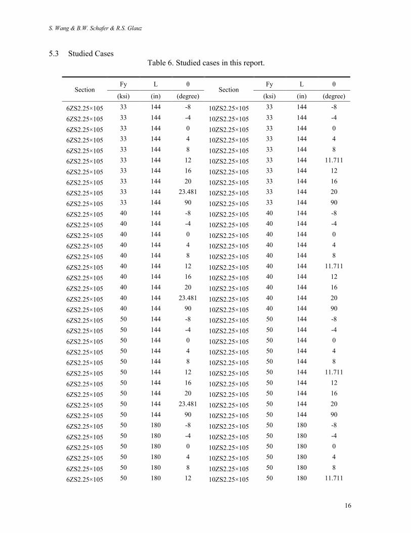
5.3 Studied Cases Table 6. Studied cases in this report.
Section Fy L θ
Section Fy L θ
(ksi) (in) (degree) (ksi) (in) (degree)
6ZS2.25×105 33 144 -8 10ZS2.25×105 33 144 -8
6ZS2.25×105 33 144 -4 10ZS2.25×105 33 144 -4
6ZS2.25×105 33 144 0 10ZS2.25×105 33 144 0
6ZS2.25×105 33 144 4 10ZS2.25×105 33 144 4
6ZS2.25×105 33 144 8 10ZS2.25×105 33 144 8
6ZS2.25×105 33 144 12 10ZS2.25×105 33 144 11.711
6ZS2.25×105 33 144 16 10ZS2.25×105 33 144 12
6ZS2.25×105 33 144 20 10ZS2.25×105 33 144 16
6ZS2.25×105 33 144 23.481 10ZS2.25×105 33 144 20
6ZS2.25×105 33 144 90 10ZS2.25×105 33 144 90
6ZS2.25×105 40 144 -8 10ZS2.25×105 40 144 -8
6ZS2.25×105 40 144 -4 10ZS2.25×105 40 144 -4
6ZS2.25×105 40 144 0 10ZS2.25×105 40 144 0
6ZS2.25×105 40 144 4 10ZS2.25×105 40 144 4
6ZS2.25×105 40 144 8 10ZS2.25×105 40 144 8
6ZS2.25×105 40 144 12 10ZS2.25×105 40 144 11.711
6ZS2.25×105 40 144 16 10ZS2.25×105 40 144 12
6ZS2.25×105 40 144 20 10ZS2.25×105 40 144 16
6ZS2.25×105 40 144 23.481 10ZS2.25×105 40 144 20
6ZS2.25×105 40 144 90 10ZS2.25×105 40 144 90
6ZS2.25×105 50 144 -8 10ZS2.25×105 50 144 -8
6ZS2.25×105 50 144 -4 10ZS2.25×105 50 144 -4
6ZS2.25×105 50 144 0 10ZS2.25×105 50 144 0
6ZS2.25×105 50 144 4 10ZS2.25×105 50 144 4
6ZS2.25×105 50 144 8 10ZS2.25×105 50 144 8
6ZS2.25×105 50 144 12 10ZS2.25×105 50 144 11.711
6ZS2.25×105 50 144 16 10ZS2.25×105 50 144 12
6ZS2.25×105 50 144 20 10ZS2.25×105 50 144 16
6ZS2.25×105 50 144 23.481 10ZS2.25×105 50 144 20
6ZS2.25×105 50 144 90 10ZS2.25×105 50 144 90
6ZS2.25×105 50 180 -8 10ZS2.25×105 50 180 -8
6ZS2.25×105 50 180 -4 10ZS2.25×105 50 180 -4
6ZS2.25×105 50 180 0 10ZS2.25×105 50 180 0
6ZS2.25×105 50 180 4 10ZS2.25×105 50 180 4
6ZS2.25×105 50 180 8 10ZS2.25×105 50 180 8
6ZS2.25×105 50 180 12 10ZS2.25×105 50 180 11.711

Inelastic Lateral-Torsional Buckling Strength Validation for Non-Principal Axis Bending Using Numerical Methods
17
6ZS2.25×105 50 180 16 10ZS2.25×105 50 180 12
6ZS2.25×105 50 180 20 10ZS2.25×105 50 180 16
6ZS2.25×105 50 180 23.481 10ZS2.25×105 50 180 20
6ZS2.25×105 50 180 90 10ZS2.25×105 50 180 90
6ZS2.25×105 50 240 -8 10ZS2.25×105 50 240 -8
6ZS2.25×105 50 240 -4 10ZS2.25×105 50 240 -4
6ZS2.25×105 50 240 0 10ZS2.25×105 50 240 0
6ZS2.25×105 50 240 4 10ZS2.25×105 50 240 4
6ZS2.25×105 50 240 8 10ZS2.25×105 50 240 8
6ZS2.25×105 50 240 12 10ZS2.25×105 50 240 11.711
6ZS2.25×105 50 240 16 10ZS2.25×105 50 240 12
6ZS2.25×105 50 240 20 10ZS2.25×105 50 240 16
6ZS2.25×105 50 240 23.481 10ZS2.25×105 50 240 20
6ZS2.25×105 50 240 90 10ZS2.25×105 50 240 90
Note: θ is angle between axis of bending and major principal axis, see Fig. 1.

S. Wang & B.W. Schafer & R.S. Glauz
18
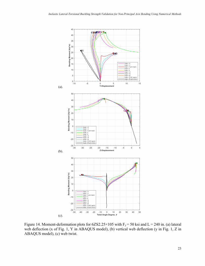
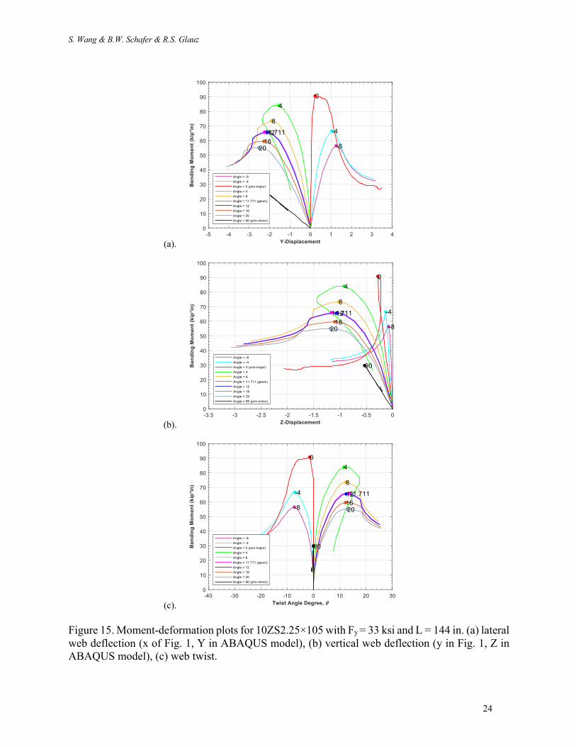
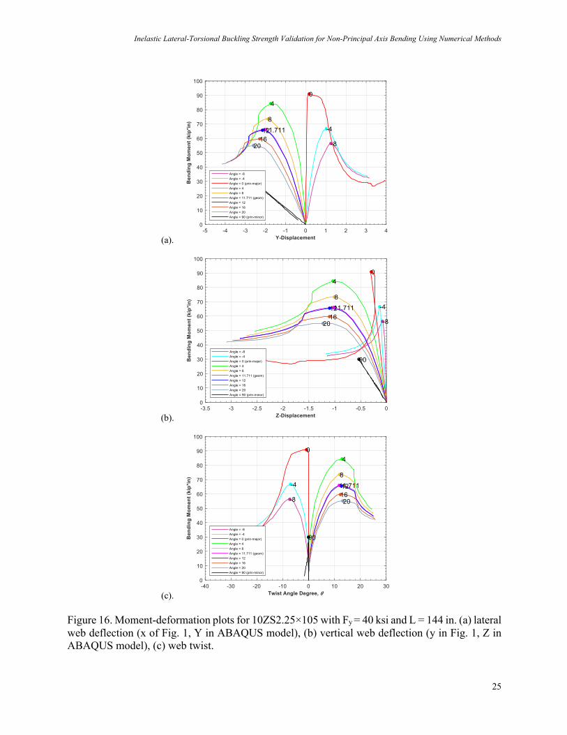
5.4 Full Moment-Deformation Results Moment-deformation results for all cases are provided in Fig. 10-19. In each case the moment vs. mid-length lateral deformation, mid-length vertical deformation, and mid-length cross-section in-plane twist are shown for the full range of different bending axes (i.e., different q) . Classical lateral-torsional buckling bifurcation behavior is observed in the case where the loading is about the major principal-axis (q=0), otherwise the inclined bending axis has an overall effect quite similar to a twist imperfection. Generally, all the simulations converge at large enough deformations to achieve a peak moment. In some cases, e.g. Fig.19 for the 10ZS2.25×105 section, more than one peak moment is observed. Members with longer unbraced lengths typically have greater potential for multiple peak moments. After bifurcation and buckling these specific members continue to rotate significantly and eventually engage minor principal-axis yielding and cross-section plastification. In terms of failure type, all the simulations deform in bending and rotation. For shorter members, the region near the web-flange connection in the web will typically yield first under tension. Subsequently the yield region extends to the flange part and eventually reaches to the lip. Once the yielded region forms a mechanism, the deformation will concentrate at this location, and the other regions will experience elastic recovery. The region near the member ends generally deforms gradually with the applied moment. For longer members, larger displacement and web rotation are observed. When the axes of bending is rotated in a positive angle direction from the principal axes the peak moment is larger than those in the negative angle direction. Using 6ZS2.25×105 section under 50ksi yield moment with 144in length as an example when the axis of bending is -8 degree inclined from major principal axis, the first yield will happen on the lip and lip-flange junction. In the end, most of the damage occurs at one side of the flange, while the other side is stable. When the axis of bending is +8 degree inclined from major principal axis, the first yield will happen at the flange-web junction. In the end, most of the damage occurs at the web along the middle line and the buckling is prevalent through the whole section at the middle. See Fig. 20 for further illustration of this phenomenon.

Inelastic Lateral-Torsional Buckling Strength Validation for Non-Principal Axis Bending Using Numerical Methods
19
(a).
(b).
(c). Figure 10. Moment-deformation plots for 6ZS2.25×105 with Fy = 33 ksi and L = 144in. (a) lateral web deflection (x of Fig. 1, Y in ABAQUS model), (b) vertical web deflection (y in Fig. 1, Z in ABAQUS model), (c) web twist.

S. Wang & B.W. Schafer & R.S. Glauz
20
(a).
(b).
(c).
Figure 11. Moment-deformation plots for 6ZS2.25×105 with Fy = 40 ksi and L= 144 in. (a) lateral web deflection (x of Fig. 1, Y in ABAQUS model), (b) vertical web deflection (y in Fig. 1, Z in ABAQUS model), (c) web twist.

Inelastic Lateral-Torsional Buckling Strength Validation for Non-Principal Axis Bending Using Numerical Methods
21
(a).
(b).
(c). Figure 12. Moment-deformation plots for 6ZS2.25×105 with Fy = 50 ksi and L = 144 in. (a) lateral web deflection (x of Fig. 1, Y in ABAQUS model), (b) vertical web deflection (y in Fig. 1, Z in ABAQUS model), (c) web twist.

S. Wang & B.W. Schafer & R.S. Glauz
22
(a).
(b).
(c). Figure 13. Moment-deformation plots for 6ZS2.25×105 with Fy = 50 ksi and L = 180 in. (a) lateral web deflection (x of Fig. 1, Y in ABAQUS model), (b) vertical web deflection (y in Fig. 1, Z in ABAQUS model), (c) web twist.
Inelastic Lateral-Torsional Buckling Strength Validation for Non-Principal Axis Bending Using Numerical Methods
23
(a).
(b).
(c). Figure 14. Moment-deformation plots for 6ZS2.25×105 with Fy = 50 ksi and L = 240 in. (a) lateral web deflection (x of Fig. 1, Y in ABAQUS model), (b) vertical web deflection (y in Fig. 1, Z in ABAQUS model), (c) web twist.
S. Wang & B.W. Schafer & R.S. Glauz
24
(a).
(b).
(c). Figure 15. Moment-deformation plots for 10ZS2.25×105 with Fy = 33 ksi and L = 144 in. (a) lateral web deflection (x of Fig. 1, Y in ABAQUS model), (b) vertical web deflection (y in Fig. 1, Z in ABAQUS model), (c) web twist.
Inelastic Lateral-Torsional Buckling Strength Validation for Non-Principal Axis Bending Using Numerical Methods
25
(a).
(b).
(c). Figure 16. Moment-deformation plots for 10ZS2.25×105 with Fy = 40 ksi and L = 144 in. (a) lateral web deflection (x of Fig. 1, Y in ABAQUS model), (b) vertical web deflection (y in Fig. 1, Z in ABAQUS model), (c) web twist.

S. Wang & B.W. Schafer & R.S. Glauz
26
(a).
(b).
(c). Figure 17. Moment-deformation plots for 10ZS2.25×105 with Fy = 50 ksi and L = 144 in. (a) lateral web deflection (x of Fig. 1, Y in ABAQUS model), (b) vertical web deflection (y in Fig. 1, Z in ABAQUS model), (c) web twist.

Inelastic Lateral-Torsional Buckling Strength Validation for Non-Principal Axis Bending Using Numerical Methods
27
(a).
(b).
(c). Figure 18. Moment-deformation plots for 10ZS2.25×105 with Fy = 50 ksi and L = 180 in. (a) lateral web deflection (x of Fig. 1, Y in ABAQUS model), (b) vertical web deflection (y in Fig. 1, Z in ABAQUS model), (c) web twist.

S. Wang & B.W. Schafer & R.S. Glauz
28
(a).
(b).
(c). Figure 19. Moment-deformation plots for 10ZS2.25×105 with Fy = 50 ksi and L = 240 in. (a) lateral web deflection (x of Fig. 1, Y in ABAQUS model), (b) vertical web deflection (y in Fig. 1, Z in ABAQUS model), (c) web twist.

Inelastic Lateral-Torsional Buckling Strength Validation for Non-Principal Axis Bending Using Numerical Methods
29
Figure 20. Lateral-torsional buckling in opposite directions for 6ZS2.25×105 with Fy = 50 ksi and L = 144 in.
S. Wang & B.W. Schafer & R.S. Glauz
30
5.5 Imperfection sensitivity Cold-formed steel members have geometric imperfections due to the production process, shipping, and installation. Results are imperfection sensitive when the models have bifurcation; however, the imperfection sensitivity is reduced if primary deformation already exists in the buckling direction, e.g. in these models when twist has already initiated. This section of the report briefly explores how imperfections impact the LTB flexural capacity for the target sections under bending moment about the major principal axis (a case that should be imperfection sensitive). A twist imperfection is applied. Only bending about the major principal axis (θ = 0) is considered. An L/2292 imperfection is applied to the 6ZS2.25×105 and 10ZS2.25×105. The imperfection factor was estimated based on a maximum imperfection twist angle of no more than 2 degrees. L is the unbraced length in the member longitudinal direction (x-axis in the ABAQUS model). Yield strength is 50 ksi for all cases in this section. As shown in the figures introduction of the 2 deg. twist imperfection eliminates the sharp bifurcation nature of the response for the case with bending about the major principal axis (angle = 0 deg.), and provides response in essence equivalent to bending about an axis approximately 2 deg. from the principal axis.

Inelastic Lateral-Torsional Buckling Strength Validation for Non-Principal Axis Bending Using Numerical Methods
31
(a).
(b).
(c).
Figure 21. Moment-web twist plots for 6ZS2.25×105 section with Fy = 50 ksi. (a) L = 144 in, (b) L = 180 in, (c) L = 240 in.

S. Wang & B.W. Schafer & R.S. Glauz
32
(a).
(b).
(c). Figure 22. Moment-web twist plots for 10ZS2.25×105 section with Fy = 50 ksi. (a) L = 144 in, (b) L = 180 in, (c) L = 240 in.

Inelastic Lateral-Torsional Buckling Strength Validation for Non-Principal Axis Bending Using Numerical Methods
33
6 Studied Design Methods
Nominal flexural capacity was predicted by three design methods: (1) AISI S100-16 approximate approach, (2) AISI S100-16 linear interaction approach, and (3) a new method considering direct bi-axial bending consistent with recent Direct Strength Method proposals. The simulation results are compared with the proposed provisions for both stability and strength determination. 6.1 Method 1: AISI S100-16 Approximate Approach Method 1 requires critical elastic lateral-torsional buckling stress 6789 to be calculated using Eq. F2.1.3-1 from AISI S100-16, which is an approximate expression for point-symmetric sections bending about the geometric axis:
F;<= =C?rAA2SE
Fσ=GσH (2)
where IJ is permitted to be conservatively taken as unity for all cases, KL is the polar radius of gyration of cross-section about shear center, M is the cross-section area, NO is the elastic section modulus, P9- and PQ are the critical axial stress for elastic buckling about x axis and torsion. The nominal stress 6R is then determined as : WhenF;<= ≥ 2.78FG , yield limitation
FW= = FG (3)
When 2.78FG > F;<= > 0.56FG , inelastic buckling
FW =109FG ^1 −
10FG36F;<=
`
(4)
When ForF;<= ≤ 0.56FG , elastic buckling
FW = F;<= (5)
The nominal flexural strength, !R9, is defined by: MW= = SEFW (6)
Common practice is to consider only bending about the geometric axis. So, if the perpendicular component of the moment is ignored, the strength for the axis of the applied moment is given by Eq. 7 where c is the angle between the axis of bending and the geometric axis.
MW =MW=
cos(β)
(7)
S. Wang & B.W. Schafer & R.S. Glauz
34
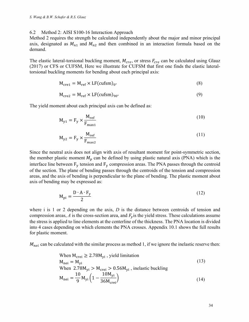
6.2 Method 2: AISI S100-16 Interaction Approach Method 2 requires the strength be calculated independently about the major and minor principal axis, designated as !R# and !R$ and then combined in an interaction formula based on the demand. The elastic lateral-torsional buckling moment, !789, or stress 6789 can be calculated using Glauz (2017) or CFS or CUFSM, Here we illustrate for CUFSM that first one finds the elastic lateral-torsional buckling moments for bending about each principal axis: M;<=# = M<=E × LF(cufsm)n° (8)
M;<=$ = M<=E × LF(cufsm)pn° (9)
The yield moment about each principal axis can be defined as: MG# = FG ×
M<=E
Fqr)#
(10)
MG$ = FG ×
M<=E
Fqr)$
(11)
Since the neutral axis does not align with axis of resultant moment for point-symmetric section, the member plastic moment !s can be defined by using plastic natural axis (PNA) which is the interface line between FG tension and FG compression areas. The PNA passes through the centroid of the section. The plane of bending passes through the centroids of the tension and compression areas, and the axis of bending is perpendicular to the plane of bending. The plastic moment about axis of bending may be expressed as:
Mtu =D ∙ A ∙ FG
2
(12)
where i is 1 or 2 depending on the axis, D is the distance between centroids of tension and compression areas, A is the cross-section area, and 6-is the yield stress. These calculations assume the stress is applied to line elements at the centerline of the thickness. The PNA location is divided into 4 cases depending on which elements the PNA crosses. Appendix 10.1 shows the full results for plastic moment. !R9x can be calculated with the similar process as method 1, if we ignore the inelastic reserve then: WhenM;<=u ≥ 2.78MGu , yield limitation
MW=u = MGu (13)
When 2.78MGu > M;<=u > 0.56MGu , inelastic buckling
MW=u =109MGu ^1 −
10MGu
36M;<=u`
(14)

Inelastic Lateral-Torsional Buckling Strength Validation for Non-Principal Axis Bending Using Numerical Methods
35
When M;<=u ≤ 0.56MGu , elastic buckling MW=u = M;<=u
(15)
If inelastic reserve is included then then following additional branches of the LTB strength curve are engaged: When M;<=u > 18.9MGu, inelastic reserve
MW=u = Mtu (16)
When M;<=u > 2.78MGu, inelastic buckling
MW=u = Mtu − +Mtu − MGu1Fyz{/y}~�{Än.$Å
n.ÅÇ≤ Mtu
(17)
A limitation imposed by S100-16 for local inelastic reserve FMGu/M;<=u − 0.23
0.37≥19
(18)
The source of Eq. (18) can be understood by recognizing with global inelastic reserve (MW=u >!-x), we should calculate the inelastic reserve for local buckling according to AISI S100-16 Eq. F3.2.3. as we want to use the minimum value between local and global buckling moment.
MWℓ = MG + (1 −1CGℓ$
)(Mt − MG) (19)
and the maximum value of CGℓ (ratio of ultimate strain to yield strain) is 3. Finally !R# and !R$ are determined by the minimum result between MW=u and MWℓu. MW# = min(MW=#,MWℓ#) (20) MW$ = min(MW=$,MWℓ$) (21)
These strength expressions are used in the linear interaction equation of S100: M#
MW#+M$
MW$≤ 1.0
(22)
For the special case of bending by moment M about an arbitrary axis at angle θ demand M# and M$ can be written simply in terms of M: M|cos θ|
MW#+M|sin θ|MW$
≤ 1.0 (23)
Which when solved for M provides the moment strength about an arbitrary axis:
MW =1
|;Aâ ä|yãå
+ |âuW ä|yãç
(24)
S. Wang & B.W. Schafer & R.S. Glauz
36
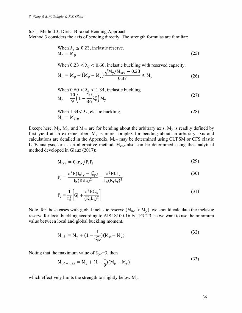
6.3 Method 3: Direct Bi-axial Bending Approach Method 3 considers the axis of bending directly. The strength formulas are familiar: When é9 ≤ 0.23, inelastic reserve.
MW = Mt (25)
When 0.23 < λ= < 0.60, inelastic buckling with reserved capacity.
MW = Mt − +Mt − MG1FMG/M;<= − 0.23
0.37≤ Mt
(26)
When 0.60 < λ= < 1.34, inelastic buckling
MW =109^1 −
1036λ=$`MG
(27)
When 1.34< λ=, elastic buckling
MW = M;<= (28)
Except here, My, Mp, and Mcre are for bending about the arbitrary axis. My is readily defined by first yield at an extreme fiber, Mp is more complex for bending about an arbitrary axis and calculations are detailed in the Appendix, Mcre may be determined using CUFSM or CFS elastic LTB analysis, or as an alternative method, M;<= also can be determined using the analytical method developed in Glauz (2017): M;<= = C?rAFP=PH (29)
P= =π$E(I)IG − I)G$ )I?(KELE)$
=π$EI#I$I?(KELE)$
(30)
PH =1rA$ñGJ +
π$ECô(KHLH)$
ö (31)
Note, for those cases with global inelastic reserve (MW= > !-), we should calculate the inelastic reserve for local buckling according to AISI S100-16 Eq. F3.2.3. as we want to use the minimum value between local and global buckling moment.
MWℓ = MG + (1 −1CGℓ$
)(Mt − MG) (32)
Noting that the maximum value of I-ℓ=3, then
MWℓÄqr) = MG + (1 −19)(Mt − MG)
(33)
which effectively limits the strength to slightly below Mp.

Inelastic Lateral-Torsional Buckling Strength Validation for Non-Principal Axis Bending Using Numerical Methods
37
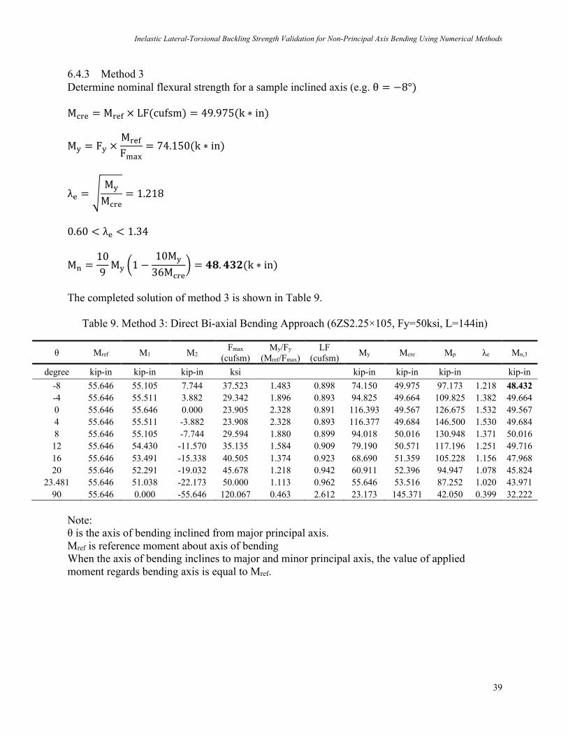
6.4 Sample Calculation for 6ZS2.25×105 Cross-section Determine the nominal flexural strength for bending about an inclined axis (i.e. θ = −8°)
6.4.1 Method 1 First, determine the nominal flexural strength for bending about geometric axis.
σ=G =π$E
^õzúz<z`$ = 21.589(ksi)
σH =1Arn$
ñGJ +π$ECô(KHLH)$
ö = 289.679(ksi)
F;<= =C?rAA2SE
Fσ=GσH = 16.67(ksi)
F;<=FG
=16.6750
= 0.334 < 0.56
FW = F;<= = 16.67(ksi) MW= = SEFW = 2.371 × 16.67 = 39.527(k ∗ in) Now, determine the nominal flexural strength for the inclined axis (e.g. θ = −8°)
MW =MW=
cos(β)=
39.527cos(−8° − 23.481°)
= ü†. °ü¢(k ∗ in)
The completed solution of method 1 is shown in Table 7.
Table 7. Method 1: AISI S100-16 Approximate Approach (6ZS2.25×105, Fy=50ksi, L=144in)
θ Ix H Sf Fcre Fn Mn,1
degree in4 in in3 ksi ksi kip-in 23.481 7.113 6 2.371 16.67 16.67 39.527
-8 46.349
-4 44.554 0 43.095 4 41.927 8 41.015 12 40.334 16 39.866 20 39.600
23.481 39.527 90 99.203

S. Wang & B.W. Schafer & R.S. Glauz
38
6.4.2 Method 2 First, determine the nominal flexural strength for bending about principal axis. M;<=# = M<=E × LF(cufsm)n = 49.567(k ∗ in) M;<=$ = M<=E × LF(cufsm)pn = 145.371(k ∗ in)
MG# = FG ×y~�£§•¶ßå
= 116.393(k ∗ in), MG$ = FG ×y~�£§•¶ßç
= 23.173(k ∗ in)
Mt# =®å©§z$
= 126.675(k ∗ in), Mt$ =®ç©§z$
= 42.050(k ∗ in) (Completed Mp refer to Appendix 10.1) M;<=#
MG#< 0.56,MW# = M;<=# = 49.567
18.9 >M;<=$
MG$> 2.7,MW=$ = Mt − +Mt − MG1
™yz
y}~�− 0.23
0.37= 33.415(k ∗ in)
MWℓ$ = MG + ´1 −1CGℓ$
¨ +Mt − MG1 = 32.222(k ∗ in)
MW$ = min(MW=$,MW≠$) = 32.222(k ∗ in) Now, determine the nominal flexural strength for the inclined axis (e.g. θ = −8°)
MW =1
|;Aâ ä|yãå
+ |âuW ä|yãç
=1
|;Aâ(ÄÆ°)|Øp.∞±Ç
+ |âuW(ÄÆ°)|Å$.$$$
= ü≤. ≤≥†(k ∗ in)
The completed solution of method 2 is shown in Table 8.
Table 8. Method 2: AISI S100-16 Interaction Approach (6ZS2.25×105, Fy=50ksi, L=144in)
θ Mref LF
(cufsm) Mcre
Fmax
(cufsm) My/Fy
(Mref/Fmax) My Mp Mn,2
degree kip-in kip-in ksi kip-in kip-in kip-in
0 55.646 0.891 49.567 23.905 2.328 116.393 126.675 49.567 (Mn1) 90 55.646 2.612 145.371 120.067 0.463 23.173 42.050 32.222 (Mn2) -8
41.156
-4 44.862
0 49.567
4 44.862
8 41.156
12 38.188
16 35.781
20 33.815
23.481 32.394
90 32.222
Inelastic Lateral-Torsional Buckling Strength Validation for Non-Principal Axis Bending Using Numerical Methods
39
6.4.3 Method 3 Determine nominal flexural strength for a sample inclined axis (e.g. θ = −8°) M;<= = M<=E × LF(cufsm) = 49.975(k ∗ in)
MG = FG ×M<=E
Fqr)= 74.150(k ∗ in)
λ= = ¥MG
M;<== 1.218
0.60 < λ= < 1.34
MW =109MG ^1 −
10MG
36M;<=` = üµ. ü°∂(k ∗ in)
The completed solution of method 3 is shown in Table 9.
Table 9. Method 3: Direct Bi-axial Bending Approach (6ZS2.25×105, Fy=50ksi, L=144in)
θ Mref M1 M2 Fmax
(cufsm) My/Fy
(Mref/Fmax) LF
(cufsm) My Mcre Mp λe Mn,3
degree kip-in kip-in kip-in ksi kip-in kip-in kip-in kip-in
-8 55.646 55.105 7.744 37.523 1.483 0.898 74.150 49.975 97.173 1.218 48.432
-4 55.646 55.511 3.882 29.342 1.896 0.893 94.825 49.664 109.825 1.382 49.664 0 55.646 55.646 0.000 23.905 2.328 0.891 116.393 49.567 126.675 1.532 49.567 4 55.646 55.511 -3.882 23.908 2.328 0.893 116.377 49.684 146.500 1.530 49.684 8 55.646 55.105 -7.744 29.594 1.880 0.899 94.018 50.016 130.948 1.371 50.016 12 55.646 54.430 -11.570 35.135 1.584 0.909 79.190 50.571 117.196 1.251 49.716 16 55.646 53.491 -15.338 40.505 1.374 0.923 68.690 51.359 105.228 1.156 47.968 20 55.646 52.291 -19.032 45.678 1.218 0.942 60.911 52.396 94.947 1.078 45.824
23.481 55.646 51.038 -22.173 50.000 1.113 0.962 55.646 53.516 87.252 1.020 43.971 90 55.646 0.000 -55.646 120.067 0.463 2.612 23.173 145.371 42.050 0.399 32.222
Note: θ is the axis of bending inclined from major principal axis. Mref is reference moment about axis of bending When the axis of bending inclines to major and minor principal axis, the value of applied moment regards bending axis is equal to Mref.
S. Wang & B.W. Schafer & R.S. Glauz
40
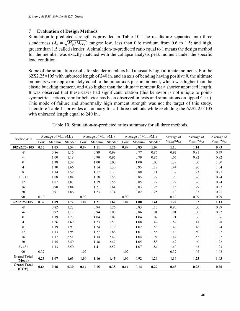
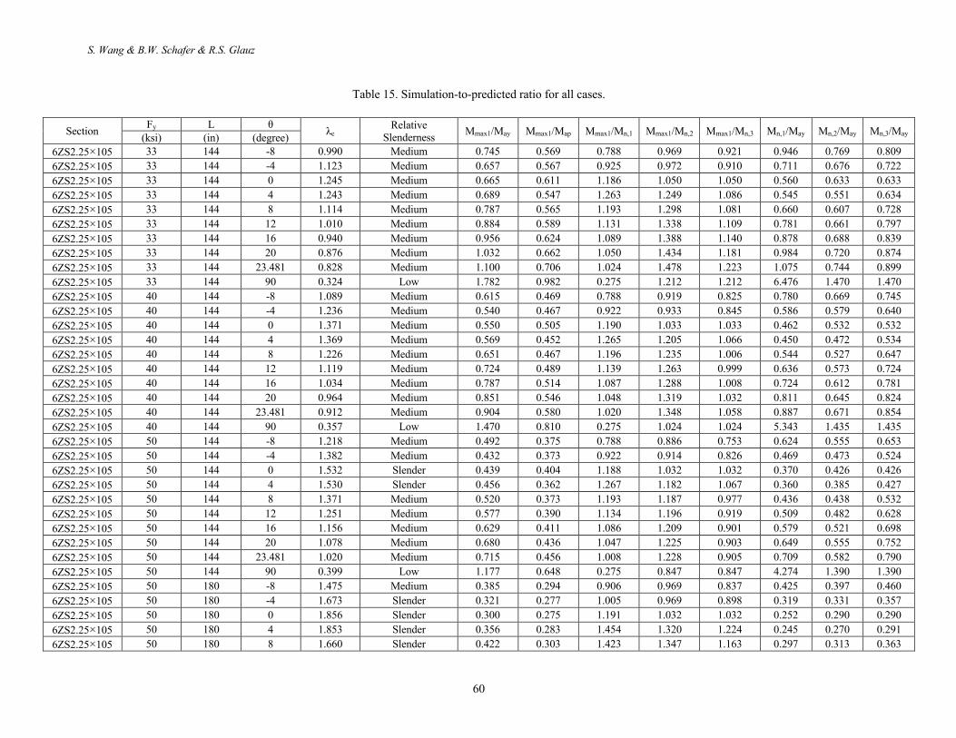
7 Evaluation of Design Methods
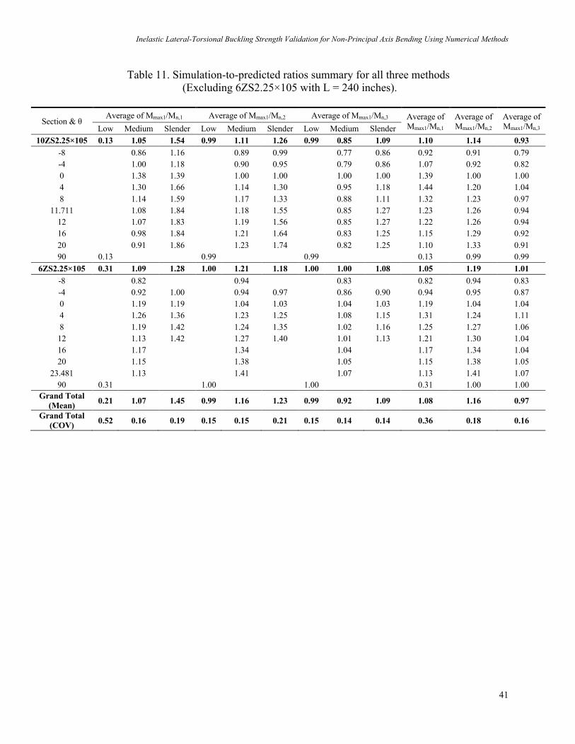
Simulation-to-predicted strength is provided in Table 10. The results are separated into three slenderness (é9 = F!-/!789 ) ranges: low, less than 0.6; medium from 0.6 to 1.5; and high, greater than 1.5 called slender. A simulation-to-predicted ratio equal to 1 means the design method for the member was exactly matched with the collapse analysis peak moment under the specific load condition. Some of the simulation results for slender members had unusually high ultimate moments. For the 6ZS2.25×105 with unbraced length of 240 in. and an axis of bending having positive θ, the ultimate moments were approximately equal to the minor axis plastic moment, which was higher than the elastic buckling moment, and also higher than the ultimate moment for a shorter unbraced length. It was observed that these cases had significant rotation (this behavior is not unique to point-symmetric sections, similar behavior has been observed in tests and simulations on lipped Cees). This mode of failure and abnormally high moment strength was not the target of this study. Therefore Table 11 provides a summary for all three methods while excluding the 6ZS2.25×105 with unbraced length equal to 240 in..
Table 10. Simulation-to-predicted ratios summary for all three methods.
Section & θ Average of Mmax1/Mn,1 Average of Mmax1/Mn,2 Average of Mmax1/Mn,3 Average of
Mmax1/Mn,1 Average of Mmax1/Mn,2
Average of Mmax1/Mn,3 Low Medium Slender Low Medium Slender Low Medium Slender
10ZS2.25×105 0.13 1.05 1.54 0.99 1.11 1.26 0.99 0.85 1.09 1.10 1.14 0.93
-8 0.86 1.16 0.89 0.99 0.77 0.86 0.92 0.91 0.79 -4 1.00 1.18 0.90 0.95 0.79 0.86 1.07 0.92 0.82 0 1.38 1.39 1.00 1.00 1.00 1.00 1.39 1.00 1.00 4 1.30 1.66 1.14 1.30 0.95 1.18 1.44 1.20 1.04 8 1.14 1.59 1.17 1.33 0.88 1.11 1.32 1.23 0.97
11.711 1.08 1.84 1.18 1.55 0.85 1.27 1.23 1.26 0.94 12 1.07 1.83 1.19 1.56 0.85 1.27 1.22 1.26 0.94 16 0.98 1.84 1.21 1.64 0.83 1.25 1.15 1.29 0.92 20 0.91 1.86 1.23 1.74 0.82 1.25 1.10 1.33 0.91 90 0.13 0.99 0.99 0.13 0.99 0.99
6ZS2.25×105 0.37 1.09 1.72 1.02 1.21 1.62 1.02 1.00 1.41 1.22 1.32 1.13
-8 0.82 1.22 0.94 1.26 0.83 1.13 0.90 1.00 0.89 -4 0.92 1.13 0.94 1.08 0.86 1.01 1.01 1.00 0.92 0 1.19 1.23 1.04 1.07 1.04 1.07 1.21 1.06 1.06 4 1.26 1.69 1.23 1.53 1.08 1.42 1.52 1.41 1.28 8 1.19 1.93 1.24 1.79 1.02 1.58 1.49 1.46 1.24 12 1.13 1.95 1.27 1.86 1.01 1.55 1.46 1.50 1.22 16 1.17 2.51 1.34 2.42 1.04 1.94 1.44 1.55 1.22 20 1.15 2.49 1.38 2.47 1.05 1.88 1.42 1.60 1.22
23.481 1.13 2.50 1.41 2.52 1.07 1.84 1.40 1.63 1.23 90 0.37 1.02 1.02 0.37 1.02 1.02
Grand Total
(Mean) 0.25 1.07 1.63 1.00 1.16 1.45 1.00 0.92 1.26 1.16 1.23 1.03
Grand Total
(COV) 0.66 0.16 0.30 0.14 0.15 0.35 0.14 0.14 0.29 0.43 0.28 0.26
Inelastic Lateral-Torsional Buckling Strength Validation for Non-Principal Axis Bending Using Numerical Methods
41
Table 11. Simulation-to-predicted ratios summary for all three methods (Excluding 6ZS2.25×105 with L = 240 inches).
Section & θ Average of Mmax1/Mn,1 Average of Mmax1/Mn,2 Average of Mmax1/Mn,3 Average of
Mmax1/Mn,1 Average of Mmax1/Mn,2
Average of Mmax1/Mn,3 Low Medium Slender Low Medium Slender Low Medium Slender
10ZS2.25×105 0.13 1.05 1.54 0.99 1.11 1.26 0.99 0.85 1.09 1.10 1.14 0.93
-8 0.86 1.16 0.89 0.99 0.77 0.86 0.92 0.91 0.79 -4 1.00 1.18 0.90 0.95 0.79 0.86 1.07 0.92 0.82 0 1.38 1.39 1.00 1.00 1.00 1.00 1.39 1.00 1.00 4 1.30 1.66 1.14 1.30 0.95 1.18 1.44 1.20 1.04 8 1.14 1.59 1.17 1.33 0.88 1.11 1.32 1.23 0.97
11.711 1.08 1.84 1.18 1.55 0.85 1.27 1.23 1.26 0.94 12 1.07 1.83 1.19 1.56 0.85 1.27 1.22 1.26 0.94 16 0.98 1.84 1.21 1.64 0.83 1.25 1.15 1.29 0.92 20 0.91 1.86 1.23 1.74 0.82 1.25 1.10 1.33 0.91 90 0.13 0.99 0.99 0.13 0.99 0.99
6ZS2.25×105 0.31 1.09 1.28 1.00 1.21 1.18 1.00 1.00 1.08 1.05 1.19 1.01
-8 0.82 0.94 0.83 0.82 0.94 0.83 -4 0.92 1.00 0.94 0.97 0.86 0.90 0.94 0.95 0.87 0 1.19 1.19 1.04 1.03 1.04 1.03 1.19 1.04 1.04 4 1.26 1.36 1.23 1.25 1.08 1.15 1.31 1.24 1.11 8 1.19 1.42 1.24 1.35 1.02 1.16 1.25 1.27 1.06 12 1.13 1.42 1.27 1.40 1.01 1.13 1.21 1.30 1.04 16 1.17 1.34 1.04 1.17 1.34 1.04 20 1.15 1.38 1.05 1.15 1.38 1.05
23.481 1.13 1.41 1.07 1.13 1.41 1.07 90 0.31 1.00 1.00 0.31 1.00 1.00
Grand Total
(Mean) 0.21 1.07 1.45 0.99 1.16 1.23 0.99 0.92 1.09 1.08 1.16 0.97
Grand Total
(COV) 0.52 0.16 0.19 0.15 0.15 0.21 0.15 0.14 0.14 0.36 0.18 0.16
S. Wang & B.W. Schafer & R.S. Glauz
42
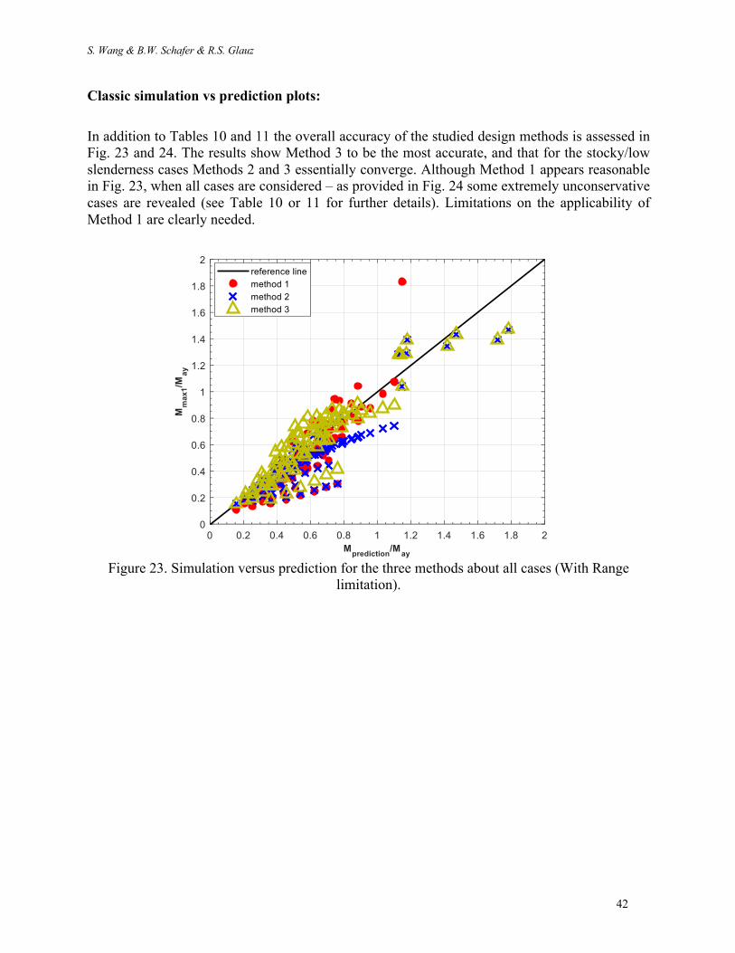
Classic simulation vs prediction plots:
In addition to Tables 10 and 11 the overall accuracy of the studied design methods is assessed in Fig. 23 and 24. The results show Method 3 to be the most accurate, and that for the stocky/low slenderness cases Methods 2 and 3 essentially converge. Although Method 1 appears reasonable in Fig. 23, when all cases are considered – as provided in Fig. 24 some extremely unconservative cases are revealed (see Table 10 or 11 for further details). Limitations on the applicability of Method 1 are clearly needed.
Figure 23. Simulation versus prediction for the three methods about all cases (With Range
limitation).

Inelastic Lateral-Torsional Buckling Strength Validation for Non-Principal Axis Bending Using Numerical Methods
43
Figure 24. Simulation versus prediction for the three methods about all cases (Without range
limitation).
S. Wang & B.W. Schafer & R.S. Glauz
44
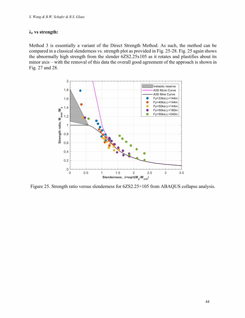
λe vs strength:
Method 3 is essentially a variant of the Direct Strength Method. As such, the method can be compared in a classical slenderness vs. strength plot as provided in Fig. 25-28. Fig. 25 again shows the abnormally high strength from the slender 6ZS2.25x105 as it rotates and plastifies about its minor axis – with the removal of this data the overall good agreement of the approach is shown in Fig. 27 and 28.
Figure 25. Strength ratio versus slenderness for 6ZS2.25×105 from ABAQUS collapse analysis.

Inelastic Lateral-Torsional Buckling Strength Validation for Non-Principal Axis Bending Using Numerical Methods
45
Figure 26. Strength ratio versus slenderness for 10ZS2.25×105 from ABAQUS collapse analysis.
Figure 27. Strength ratio versus slenderness for all cases from ABAQUS collapse analysis (With
case detail, excluding 6ZS2.25×105 with L = 240 inches).

S. Wang & B.W. Schafer & R.S. Glauz
46
Figure 28. Strength ratio versus slenderness for all cases from ABAQUS collapse analysis
(Excluding 6ZS2.25×105 with L = 240 inches).

Inelastic Lateral-Torsional Buckling Strength Validation for Non-Principal Axis Bending Using Numerical Methods
47
Interaction diagrams:
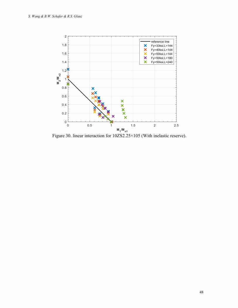
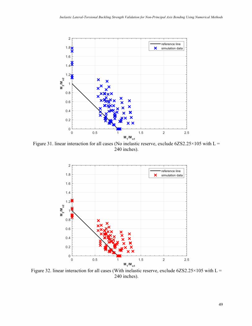
Method 2 uses an interaction equation approach to strength prediction, therefore directly examining the performance against the interaction equation in AISI provides a useful assessment of the method as shown in Fig. 29-32. Method 2 is consistently conservative. As the difference between Fig. 31 and Fig. 32 indicates including inelastic reserve in the strength prediction is important for accuracy.
Figure 29. linear interaction for 6ZS2.25×105 (With inelastic reserve).
S. Wang & B.W. Schafer & R.S. Glauz
48
Figure 30. linear interaction for 10ZS2.25×105 (With inelastic reserve).
Inelastic Lateral-Torsional Buckling Strength Validation for Non-Principal Axis Bending Using Numerical Methods
49
Figure 31. linear interaction for all cases (No inelastic reserve, exclude 6ZS2.25×105 with L =
240 inches).
Figure 32. linear interaction for all cases (With inelastic reserve, exclude 6ZS2.25×105 with L =
240 inches).
S. Wang & B.W. Schafer & R.S. Glauz
50
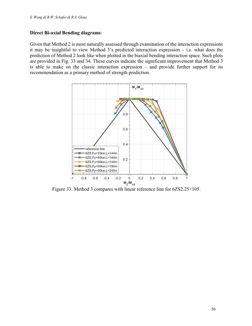
Direct Bi-axial Bending diagrams: Given that Method 2 is most naturally assessed through examination of the interaction expressions it may be insightful to view Method 3’s predicted interaction expression – i.e. what does the prediction of Method 2 look like when plotted in the biaxial bending interaction space. Such plots are provided in Fig. 33 and 34. These curves indicate the significant improvement that Method 3 is able to make on the classic interaction expression – and provide further support for its recommendation as a primary method of strength prediction.
Figure 33. Method 3 compares with linear reference line for 6ZS2.25×105.

Inelastic Lateral-Torsional Buckling Strength Validation for Non-Principal Axis Bending Using Numerical Methods
51
Figure 34. Method 3 compares with linear reference line for 10ZS2.25×105.

S. Wang & B.W. Schafer & R.S. Glauz
52
8 Conclusions
Applications for non-symmetric cold-formed steel members commonly induce biaxial bending since loads are almost never aligned with the principal axes of the section. Recently, Glauz (2017) developed an analytical solution for the lateral-torsional buckling (LTB) moment (Mcre) of a non-symmetric section bent about an arbitrary axis. These provisions could potentially replace simplified expressions used in AISI-S100-16 for Mcre; however, the impact of applying this expression in design has not been fully assessed for LTB limit states. To assess the implications of employing the more accurate Mcre solution a series of shell finite element collapse analyses where performed on two Zee-sections: 6ZS2.25×105 and 10ZS2.25×105, previously identified to be controlled by LTB, as opposed to local or distortional buckling. The collapse simulations were performed on sharp corner models of the Zee shapes under isolated and equal end moments and were augmented by eigenvalue buckling analysis in ABAQUS and finite strip method analyses conducted in CUFSM and in CFS. All of the ABAQUS shell finite element collapse simulations converged at large enough deformations to achieve at least one peak moment. After bifurcation and buckling, some of the longer studied members continued to rotate significantly, sometimes resulting in secondary peak moments – generally consistent with plastic bending capacity about the minor principal axis of the section. Three design approaches were compared to the conducted simulations: (1) AISI-S100-16 approximate approach, (2) AISI-S100-16 interaction approach, and (3) direct bi-axial bending approach. For method 1, the AISI S100-16 approximate approach uses a conservatively low estimate of Mcre, but ignores bending about anything other than the geometric axis – this combination of conservative and unconservative assumptions balances out as long as the bending axis is reasonably close to the geometric axis – for large deviations it is problematic and invalid. For method 2, the AISI-S100-16 interaction approach uses the elastic buckling and strength about the major- and minor-principal axes as anchors and gives reasonable predictions, but can be overly conservative particularly if inelastic reserve is ignored. For method 3, the direct bi-axial bending approach is a rational extension of the Direct Strength Method and uses the buckling and yielding solutions about the arbitrary axis of bending - and is shown to provide the best overall prediction of the strength. Many of the bi-axial bending finite element collapse simulations exhibited large rotations which would likely be deemed unacceptable in practice. Future study would be appropriate to estimate the rotation and establish serviceability limits or guidelines. In addition, this study did not assess the impact of moment gradient, nor that of local or distortional buckling for bending about arbitrary axes.

Inelastic Lateral-Torsional Buckling Strength Validation for Non-Principal Axis Bending Using Numerical Methods
53
9 References
R.S. Glauz, Elastic lateral-torsional buckling of general cold-formed steel under uniform moment, Thin-walled structures 119(2017)586-592
Vahid Zeinoddini, Benjamin W. Schafer, Global Imperfections and dimensional variations in cold-formed steel
members, International Journal of Structural Stability and Dynamics, Vol.11, No.5 (2011)827-854 American Iron and Steel Institute (2016), AISI S100-16, North American Specification for the Design of Cold-Formed
Steel Structural Members, Washington, DC, 2016 R.S. Glauz, CFS [Cold-Formed Steel Design Software] (Version 12), RSG Software, Inc., Retrieved from
https://www.rsgsoftware.com Benjamin W. Schafer , CUFSM [Cold-Formed Steel Design Software] (version 5.03), Thin-walled structure lab,
Retrieved from https://www.ce.jhu.edu/bschafer/cufsm/ ABAQUS (version 6.13)
S. Wang & B.W. Schafer & R.S. Glauz
54
10 Appendices
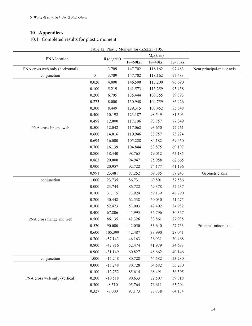
10.1 Completed results for plastic moment
Table 12. Plastic Moment for 6ZS2.25×105.
PNA location θ (degree) Mp (k-in)
Fy=50ksi Fy=40ksi Fy=33ksi
PNA cross web only (horizontal) 3.709 147.702 118.162 97.483 Near principal-major axis
conjunction 0 3.709 147.702 118.162 97.483
PNA cross lip and web
0.020 4.000 146.500 117.200 96.690
0.100 5.219 141.573 113.259 93.438
0.200 6.795 135.444 108.355 89.393
0.273 8.000 130.948 104.759 86.426
0.300 8.449 129.315 103.452 85.348
0.400 10.192 123.187 98.549 81.303
0.498 12.000 117.196 93.757 77.349
0.500 12.042 117.062 93.650 77.261
0.600 14.016 110.946 88.757 73.224
0.694 16.000 105.228 84.182 69.450
0.700 16.139 104.844 83.875 69.197
0.800 18.440 98.765 79.012 65.185
0.863 20.000 94.947 75.958 62.665
0.900 20.957 92.722 74.177 61.196
0.991 23.481 87.252 69.385 57.243 Geometric axis
conjunction 1.000 23.735 86.731 69.801 57.586
PNA cross flange and web
0.000 23.744 86.722 69.378 57.237
0.100 31.115 73.924 59.139 48.790
0.200 40.448 62.538 50.030 41.275
0.300 52.473 53.003 42.402 34.982
0.400 67.806 45.995 36.796 30.357
0.500 86.135 42.326 33.861 27.935
0.520 90.000 42.050 33.640 27.753 Principal-minor axis
0.600 105.399 42.487 33.990 28.041
0.700 -57.143 46.163 36.931 30.468
0.800 -42.816 52.474 41.979 34.633
0.900 -31.149 60.827 48.662 40.146
conjunction 1.000 -15.248 80.728 64.582 53.280
PNA cross web only (vertical)
0.000 -15.248 80.728 64.582 53.280
0.100 -12.752 85.614 68.491 56.505
0.200 -10.518 90.633 72.507 59.818
0.300 -8.510 95.764 76.611 63.204
0.327 -8.000 97.173 77.738 64.134
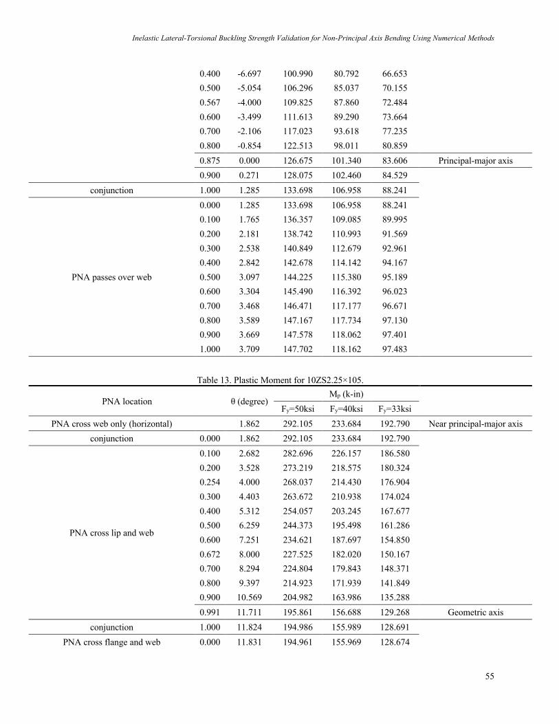
Inelastic Lateral-Torsional Buckling Strength Validation for Non-Principal Axis Bending Using Numerical Methods
55
0.400 -6.697 100.990 80.792 66.653
0.500 -5.054 106.296 85.037 70.155
0.567 -4.000 109.825 87.860 72.484
0.600 -3.499 111.613 89.290 73.664
0.700 -2.106 117.023 93.618 77.235
0.800 -0.854 122.513 98.011 80.859
0.875 0.000 126.675 101.340 83.606 Principal-major axis
0.900 0.271 128.075 102.460 84.529
conjunction 1.000 1.285 133.698 106.958 88.241
PNA passes over web
0.000 1.285 133.698 106.958 88.241
0.100 1.765 136.357 109.085 89.995
0.200 2.181 138.742 110.993 91.569
0.300 2.538 140.849 112.679 92.961
0.400 2.842 142.678 114.142 94.167
0.500 3.097 144.225 115.380 95.189
0.600 3.304 145.490 116.392 96.023
0.700 3.468 146.471 117.177 96.671
0.800 3.589 147.167 117.734 97.130
0.900 3.669 147.578 118.062 97.401
1.000 3.709 147.702 118.162 97.483
Table 13. Plastic Moment for 10ZS2.25×105.
PNA location θ (degree) Mp (k-in)
Fy=50ksi Fy=40ksi Fy=33ksi
PNA cross web only (horizontal) 1.862 292.105 233.684 192.790 Near principal-major axis
conjunction 0.000 1.862 292.105 233.684 192.790
PNA cross lip and web
0.100 2.682 282.696 226.157 186.580
0.200 3.528 273.219 218.575 180.324
0.254 4.000 268.037 214.430 176.904
0.300 4.403 263.672 210.938 174.024
0.400 5.312 254.057 203.245 167.677
0.500 6.259 244.373 195.498 161.286
0.600 7.251 234.621 187.697 154.850
0.672 8.000 227.525 182.020 150.167
0.700 8.294 224.804 179.843 148.371
0.800 9.397 214.923 171.939 141.849
0.900 10.569 204.982 163.986 135.288
0.991 11.711 195.861 156.688 129.268 Geometric axis
conjunction 1.000 11.824 194.986 155.989 128.691
PNA cross flange and web 0.000 11.831 194.961 155.969 128.674

S. Wang & B.W. Schafer & R.S. Glauz
56
0.006 12.000 193.662 154.930 127.817
0.100 14.975 172.658 138.126 113.954
0.130 16.000 166.165 132.932 109.669
0.200 18.662 150.901 120.721 99.595
0.232 20.000 144.026 115.221 95.057
0.300 23.134 129.774 103.819 85.651
0.400 28.797 109.438 87.550 72.229
0.500 36.352 90.216 72.173 59.543
0.600 47.045 72.773 58.218 48.030
0.700 62.892 58.496 46.797 38.608
0.800 85.761 50.017 40.014 33.012
0.816 90.000 49.434 39.547 32.626 Principal-minor axis
0.900 -66.128 50.830 40.664 33.548
conjunction 1.000 -22.935 89.488 71.590 59.062
PNA cross web only (vertical)
0.000 -22.935 89.488 71.590 59.062
0.100 -17.641 104.121 83.297 68.720
0.200 -13.661 119.406 95.525 78.808
0.300 -10.581 135.122 108.098 89.181
0.400 -8.136 151.134 120.908 99.749
0.406 -8.000 152.136 121.709 100.410
0.500 -6.150 167.358 133.886 110.456
0.600 -4.440 183.676 146.941 121.226
0.629 -4.000 188.477 150.781 124.395
0.700 -3.030 200.149 160.119 132.098
0.800 -1.854 216.742 173.394 143.050
0.900 -0.864 233.429 186.743 154.063
conjunction 1.000 -0.021 250.191 200.153 165.126
PNA passes over web
0.000 -0.021 250.191 200.153 165.126
0.005 0.000 250.625 200.500 165.413 Principal-major axis
0.100 0.366 258.148 206.518 170.377
0.200 0.694 265.274 212.219 175.081
0.300 0.972 271.567 217.253 179.234
0.400 1.205 277.023 221.619 182.835
0.500 1.398 281.641 225.313 185.883
0.600 1.555 285.419 228.335 188.377
0.700 1.678 288.355 230.684 190.314
0.800 1.769 290.449 232.359 191.696
0.900 1.830 291.699 233.359 192.521
1.000 1.862 292.105 233.684 192.790
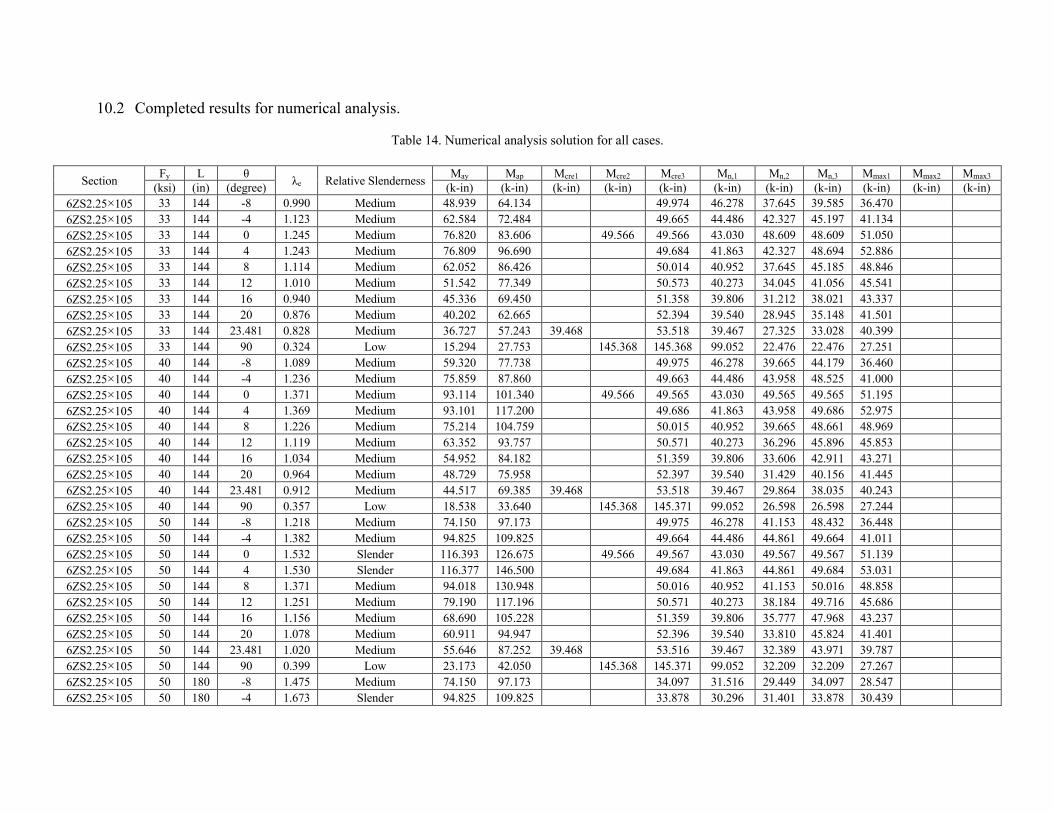
10.2 Completed results for numerical analysis.
Table 14. Numerical analysis solution for all cases.
Section Fy L θ λe Relative Slenderness May Map Mcre1 Mcre2 Mcre3 Mn,1 Mn,2 Mn,3 Mmax1 Mmax2 Mmax3 (ksi) (in) (degree) (k-in) (k-in) (k-in) (k-in) (k-in) (k-in) (k-in) (k-in) (k-in) (k-in) (k-in)
6ZS2.25×105 33 144 -8 0.990 Medium 48.939 64.134 49.974 46.278 37.645 39.585 36.470
6ZS2.25×105 33 144 -4 1.123 Medium 62.584 72.484 49.665 44.486 42.327 45.197 41.134
6ZS2.25×105 33 144 0 1.245 Medium 76.820 83.606 49.566 49.566 43.030 48.609 48.609 51.050
6ZS2.25×105 33 144 4 1.243 Medium 76.809 96.690 49.684 41.863 42.327 48.694 52.886
6ZS2.25×105 33 144 8 1.114 Medium 62.052 86.426 50.014 40.952 37.645 45.185 48.846
6ZS2.25×105 33 144 12 1.010 Medium 51.542 77.349 50.573 40.273 34.045 41.056 45.541
6ZS2.25×105 33 144 16 0.940 Medium 45.336 69.450 51.358 39.806 31.212 38.021 43.337
6ZS2.25×105 33 144 20 0.876 Medium 40.202 62.665 52.394 39.540 28.945 35.148 41.501
6ZS2.25×105 33 144 23.481 0.828 Medium 36.727 57.243 39.468 53.518 39.467 27.325 33.028 40.399
6ZS2.25×105 33 144 90 0.324 Low 15.294 27.753 145.368 145.368 99.052 22.476 22.476 27.251
6ZS2.25×105 40 144 -8 1.089 Medium 59.320 77.738 49.975 46.278 39.665 44.179 36.460
6ZS2.25×105 40 144 -4 1.236 Medium 75.859 87.860 49.663 44.486 43.958 48.525 41.000
6ZS2.25×105 40 144 0 1.371 Medium 93.114 101.340 49.566 49.565 43.030 49.565 49.565 51.195
6ZS2.25×105 40 144 4 1.369 Medium 93.101 117.200 49.686 41.863 43.958 49.686 52.975
6ZS2.25×105 40 144 8 1.226 Medium 75.214 104.759 50.015 40.952 39.665 48.661 48.969
6ZS2.25×105 40 144 12 1.119 Medium 63.352 93.757 50.571 40.273 36.296 45.896 45.853
6ZS2.25×105 40 144 16 1.034 Medium 54.952 84.182 51.359 39.806 33.606 42.911 43.271
6ZS2.25×105 40 144 20 0.964 Medium 48.729 75.958 52.397 39.540 31.429 40.156 41.445
6ZS2.25×105 40 144 23.481 0.912 Medium 44.517 69.385 39.468 53.518 39.467 29.864 38.035 40.243
6ZS2.25×105 40 144 90 0.357 Low 18.538 33.640 145.368 145.371 99.052 26.598 26.598 27.244
6ZS2.25×105 50 144 -8 1.218 Medium 74.150 97.173 49.975 46.278 41.153 48.432 36.448
6ZS2.25×105 50 144 -4 1.382 Medium 94.825 109.825 49.664 44.486 44.861 49.664 41.011
6ZS2.25×105 50 144 0 1.532 Slender 116.393 126.675 49.566 49.567 43.030 49.567 49.567 51.139
6ZS2.25×105 50 144 4 1.530 Slender 116.377 146.500 49.684 41.863 44.861 49.684 53.031
6ZS2.25×105 50 144 8 1.371 Medium 94.018 130.948 50.016 40.952 41.153 50.016 48.858
6ZS2.25×105 50 144 12 1.251 Medium 79.190 117.196 50.571 40.273 38.184 49.716 45.686
6ZS2.25×105 50 144 16 1.156 Medium 68.690 105.228 51.359 39.806 35.777 47.968 43.237
6ZS2.25×105 50 144 20 1.078 Medium 60.911 94.947 52.396 39.540 33.810 45.824 41.401
6ZS2.25×105 50 144 23.481 1.020 Medium 55.646 87.252 39.468 53.516 39.467 32.389 43.971 39.787
6ZS2.25×105 50 144 90 0.399 Low 23.173 42.050 145.368 145.371 99.052 32.209 32.209 27.267
6ZS2.25×105 50 180 -8 1.475 Medium 74.150 97.173 34.097 31.516 29.449 34.097 28.547
6ZS2.25×105 50 180 -4 1.673 Slender 94.825 109.825 33.878 30.296 31.401 33.878 30.439
S. Wang & B.W. Schafer & R.S. Glauz
58
6ZS2.25×105 50 180 0 1.856 Slender 116.393 126.675 33.806 33.806 29.304 33.806 33.806 34.890
6ZS2.25×105 50 180 4 1.853 Slender 116.377 146.500 33.883 28.510 31.401 33.883 41.457
6ZS2.25×105 50 180 8 1.660 Slender 94.018 130.948 34.109 27.889 29.449 34.109 39.676
6ZS2.25×105 50 180 12 1.515 Slender 79.190 117.196 34.489 27.426 27.854 34.489 38.952
6ZS2.25×105 50 180 16 1.400 Medium 68.690 105.228 35.032 27.108 26.545 35.032 38.952
6ZS2.25×105 50 180 20 1.305 Medium 60.911 94.947 35.747 26.927 25.473 35.645 39.119
6ZS2.25×105 50 180 23.481 1.234 Medium 55.646 87.252 26.878 36.522 26.878 24.702 35.661 39.453
6ZS2.25×105 50 180 90 0.469 Low 23.173 42.050 105.222 105.222 67.456 29.842 29.842 27.155
6ZS2.25×105 50 240 -8 1.857 Slender 74.150 97.173 21.496 19.840 19.139 21.496 24.206 31.885
6ZS2.25×105 50 240 -4 2.107 Slender 94.825 109.825 21.355 19.072 20.117 21.355 24.095 23.316
6ZS2.25×105 50 240 0 2.337 Slender 116.393 126.675 21.309 21.309 18.447 21.309 21.309 24.262 22.871
6ZS2.25×105 50 240 4 2.334 Slender 116.377 146.500 21.357 17.947 20.117 21.357 42.069
6ZS2.25×105 50 240 8 2.091 Slender 94.018 130.948 21.499 17.557 19.139 21.499 42.792
6ZS2.25×105 50 240 12 1.909 Slender 79.190 117.196 21.739 17.265 18.337 21.739 42.681
6ZS2.25×105 50 240 16 1.764 Slender 68.690 105.228 22.082 17.065 17.683 22.082 42.792
6ZS2.25×105 50 240 20 1.644 Slender 60.911 94.947 22.534 16.951 17.154 22.534 42.291
6ZS2.25×105 50 240 23.481 1.555 Slender 55.646 87.252 17.346 23.025 16.920 16.784 23.025 42.347
6ZS2.25×105 50 240 90 0.582 Low 23.173 42.050 68.417 68.417 42.464 24.092 24.092 26.599 -26.933
10ZS2.25×105 33 144 -8 0.895 Medium 73.195 100.410 91.459 68.302 59.871 63.248 56.444
10ZS2.25×105 33 144 -4 1.065 Medium 103.006 124.395 90.835 66.796 71.861 78.399 66.684
10ZS2.25×105 33 144 0 1.310 Medium 155.397 165.413 90.610 90.610 65.667 90.408 90.408 90.743 27.556
10ZS2.25×105 33 144 4 1.172 Medium 124.579 176.904 90.760 64.887 71.861 85.643 84.083 -88.236
10ZS2.25×105 33 144 8 1.040 Medium 98.845 150.167 91.309 64.435 59.871 76.802 73.510
10ZS2.25×105 33 144 11.711 0.950 Medium 83.251 129.268 64.301 92.175 64.300 52.041 69.294 65.851
10ZS2.25×105 33 144 12 0.944 Medium 82.254 127.817 92.258 64.301 51.525 68.759 65.601
10ZS2.25×105 33 144 16 0.869 Medium 70.728 109.669 93.624 64.481 45.415 62.095 59.607
10ZS2.25×105 33 144 20 0.808 Medium 62.301 95.057 95.430 64.979 40.778 56.670 55.029
10ZS2.25×105 33 144 90 0.255 Low 17.373 32.626 267.035 267.035 316.787 24.207 24.207 29.804
10ZS2.25×105 40 144 -8 0.985 Medium 88.721 121.709 91.461 68.302 63.116 72.016 56.409
10ZS2.25×105 40 144 -4 1.172 Medium 124.856 150.781 90.838 66.796 74.226 85.762 66.701
10ZS2.25×105 40 144 0 1.442 Medium 188.360 200.500 90.607 90.607 65.667 90.617 90.607 90.920 30.878
10ZS2.25×105 40 144 4 1.290 Medium 151.004 214.430 90.763 64.887 74.226 90.243 84.361
10ZS2.25×105 40 144 8 1.145 Medium 119.812 182.020 91.308 64.435 63.116 84.602 73.462
10ZS2.25×105 40 144 11.711 1.046 Medium 100.910 156.688 64.301 92.172 64.300 55.633 78.024 65.995
10ZS2.25×105 40 144 12 1.040 Medium 99.702 154.930 92.254 64.301 55.133 77.524 65.591
10ZS2.25×105 40 144 16 0.957 Medium 85.731 132.932 93.621 64.481 49.155 71.026 59.638
10ZS2.25×105 40 144 20 0.890 Medium 75.516 115.221 95.434 64.979 44.542 65.464 54.996
10ZS2.25×105 40 144 90 0.281 Low 21.058 39.547 267.038 267.038 316.787 28.312 28.312 29.869
10ZS2.25×105 50 144 -8 1.101 Medium 110.901 152.136 91.460 68.302 66.423 81.719 56.383

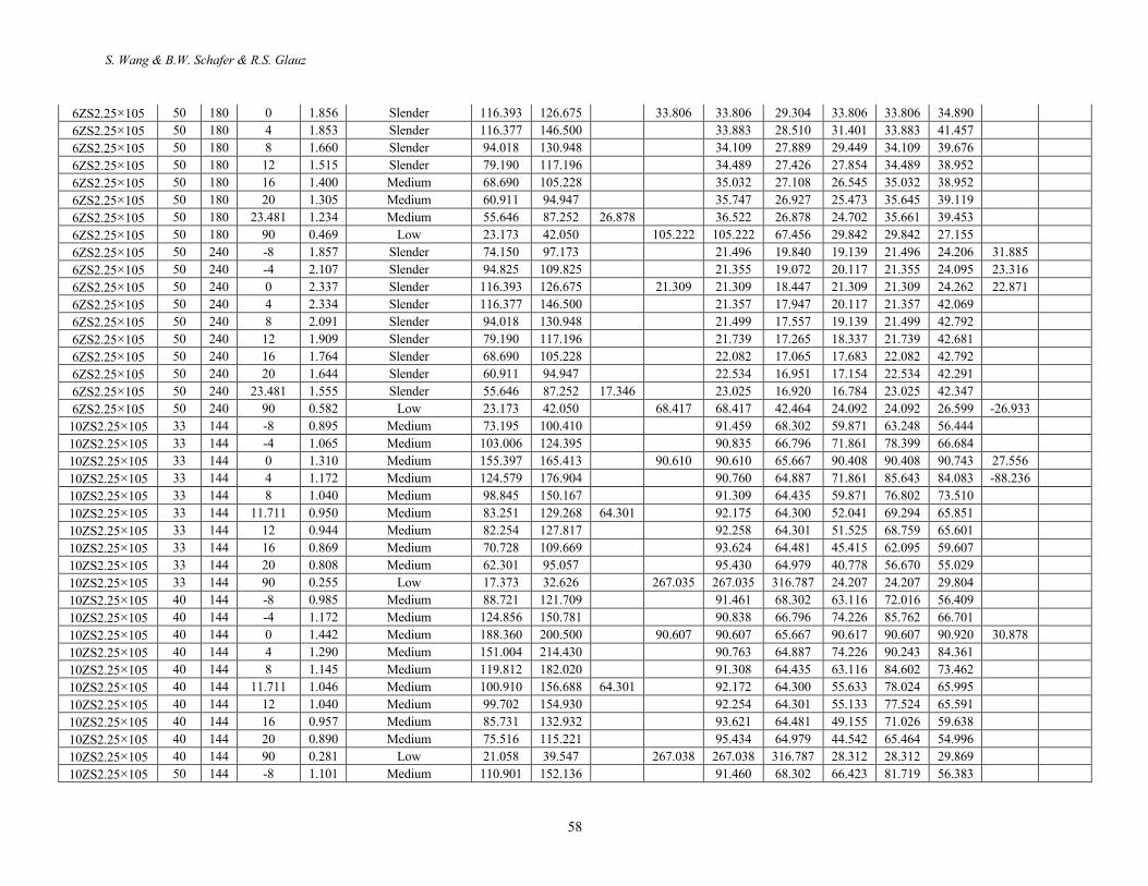
Inelastic Lateral-Torsional Buckling Strength Validation for Non-Principal Axis Bending Using Numerical Methods
59
10ZS2.25×105 50 144 -4 1.311 Medium 156.070 188.477 90.838 66.796 76.467 90.650 66.600
10ZS2.25×105 50 144 0 1.612 Slender 235.450 250.625 90.608 90.608 65.667 90.608 90.608 90.819
10ZS2.25×105 50 144 4 1.442 Medium 188.756 268.037 90.762 64.887 76.467 90.762 84.512
10ZS2.25×105 50 144 8 1.281 Medium 149.765 227.525 91.307 64.435 66.423 90.588 73.538
10ZS2.25×105 50 144 11.711 1.170 Medium 126.137 195.861 64.301 92.170 64.300 59.439 86.874 66.096
10ZS2.25×105 50 144 12 1.169 Medium 126.137 193.662 92.254 64.301 58.966 86.923 65.591
10ZS2.25×105 50 144 16 1.070 Medium 107.163 166.165 93.620 64.481 53.247 81.211 59.663
10ZS2.25×105 50 144 20 0.995 Medium 94.395 144.026 95.434 64.979 48.756 76.067 54.996
10ZS2.25×105 50 144 90 0.314 Low 26.323 49.434 267.033 267.033 316.787 33.732 33.732 29.895 29.895
10ZS2.25×105 50 180 -8 1.353 Medium 110.901 152.136 60.572 45.148 48.480 60.572 43.265
10ZS2.25×105 50 180 -4 1.611 Slender 156.070 188.477 60.155 44.152 53.503 60.155 48.563
10ZS2.25×105 50 180 0 1.981 Slender 235.450 250.625 90.608 60.012 43.406 60.012 60.012 59.915
10ZS2.25×105 50 180 4 1.772 Slender 188.756 268.037 60.140 42.890 53.503 60.140 62.690
10ZS2.25×105 50 180 8 1.573 Slender 149.765 227.525 60.540 42.591 48.480 60.540 56.636
10ZS2.25×105 50 180 11.711 1.436 Medium 126.137 195.861 42.504 61.163 42.502 44.775 61.163 52.473
10ZS2.25×105 50 180 12 1.435 Medium 126.137 193.662 61.223 42.503 44.518 61.223 52.221
10ZS2.25×105 50 180 16 1.313 Medium 107.163 166.165 62.203 42.622 41.341 62.089 48.941
10ZS2.25×105 50 180 20 1.219 Medium 94.395 144.026 63.503 42.951 38.763 61.576 46.923
10ZS2.25×105 50 180 90 0.341 Low 26.323 49.434 267.033 225.950 209.396 33.732 33.732 29.895
10ZS2.25×105 50 240 -8 1.747 Slender 110.901 152.136 36.358 27.056 31.628 36.358 31.282 26.489
10ZS2.25×105 50 240 -4 2.079 Slender 156.070 188.477 36.104 26.460 33.600 36.104 33.174 33.931
10ZS2.25×105 50 240 0 2.557 Slender 235.450 250.625 90.608 36.021 26.013 36.021 36.021 36.454 35.823 33.174 10ZS2.25×105 50 240 4 2.287 Slender 188.756 268.037 36.103 25.703 33.600 36.103 47.806 44.400 40.742 10ZS2.25×105 50 240 8 2.030 Slender 149.765 227.525 36.355 25.525 31.628 36.355 47.049 44.779 44.022 10ZS2.25×105 50 240 11.711 1.853 Slender 126.137 195.861 25.473 36.744 25.471 30.120 36.744 46.797 45.283 44.526 10ZS2.25×105 50 240 12 1.852 Slender 126.137 193.662 36.780 25.471 30.013 36.780 46.671 45.283 44.400 10ZS2.25×105 50 240 16 1.693 Slender 107.163 166.165 37.391 25.543 28.688 37.391 46.923 45.914
10ZS2.25×105 50 240 20 1.572 Slender 94.395 144.026 38.198 25.740 27.604 38.198 47.932 40.995
10ZS2.25×105 50 240 90 0.403 Low 26.323 49.434 267.033 161.695 125.489 33.732 33.732 29.642
S. Wang & B.W. Schafer & R.S. Glauz
60
Table 15. Simulation-to-predicted ratio for all cases.
Section Fy L θ λe Relative Slenderness Mmax1/May Mmax1/Map Mmax1/Mn,1 Mmax1/Mn,2 Mmax1/Mn,3 Mn,1/May Mn,2/May Mn,3/May (ksi) (in) (degree)
6ZS2.25×105 33 144 -8 0.990 Medium 0.745 0.569 0.788 0.969 0.921 0.946 0.769 0.809 6ZS2.25×105 33 144 -4 1.123 Medium 0.657 0.567 0.925 0.972 0.910 0.711 0.676 0.722 6ZS2.25×105 33 144 0 1.245 Medium 0.665 0.611 1.186 1.050 1.050 0.560 0.633 0.633 6ZS2.25×105 33 144 4 1.243 Medium 0.689 0.547 1.263 1.249 1.086 0.545 0.551 0.634 6ZS2.25×105 33 144 8 1.114 Medium 0.787 0.565 1.193 1.298 1.081 0.660 0.607 0.728 6ZS2.25×105 33 144 12 1.010 Medium 0.884 0.589 1.131 1.338 1.109 0.781 0.661 0.797 6ZS2.25×105 33 144 16 0.940 Medium 0.956 0.624 1.089 1.388 1.140 0.878 0.688 0.839 6ZS2.25×105 33 144 20 0.876 Medium 1.032 0.662 1.050 1.434 1.181 0.984 0.720 0.874 6ZS2.25×105 33 144 23.481 0.828 Medium 1.100 0.706 1.024 1.478 1.223 1.075 0.744 0.899 6ZS2.25×105 33 144 90 0.324 Low 1.782 0.982 0.275 1.212 1.212 6.476 1.470 1.470 6ZS2.25×105 40 144 -8 1.089 Medium 0.615 0.469 0.788 0.919 0.825 0.780 0.669 0.745 6ZS2.25×105 40 144 -4 1.236 Medium 0.540 0.467 0.922 0.933 0.845 0.586 0.579 0.640 6ZS2.25×105 40 144 0 1.371 Medium 0.550 0.505 1.190 1.033 1.033 0.462 0.532 0.532 6ZS2.25×105 40 144 4 1.369 Medium 0.569 0.452 1.265 1.205 1.066 0.450 0.472 0.534 6ZS2.25×105 40 144 8 1.226 Medium 0.651 0.467 1.196 1.235 1.006 0.544 0.527 0.647 6ZS2.25×105 40 144 12 1.119 Medium 0.724 0.489 1.139 1.263 0.999 0.636 0.573 0.724 6ZS2.25×105 40 144 16 1.034 Medium 0.787 0.514 1.087 1.288 1.008 0.724 0.612 0.781 6ZS2.25×105 40 144 20 0.964 Medium 0.851 0.546 1.048 1.319 1.032 0.811 0.645 0.824 6ZS2.25×105 40 144 23.481 0.912 Medium 0.904 0.580 1.020 1.348 1.058 0.887 0.671 0.854 6ZS2.25×105 40 144 90 0.357 Low 1.470 0.810 0.275 1.024 1.024 5.343 1.435 1.435 6ZS2.25×105 50 144 -8 1.218 Medium 0.492 0.375 0.788 0.886 0.753 0.624 0.555 0.653 6ZS2.25×105 50 144 -4 1.382 Medium 0.432 0.373 0.922 0.914 0.826 0.469 0.473 0.524 6ZS2.25×105 50 144 0 1.532 Slender 0.439 0.404 1.188 1.032 1.032 0.370 0.426 0.426 6ZS2.25×105 50 144 4 1.530 Slender 0.456 0.362 1.267 1.182 1.067 0.360 0.385 0.427 6ZS2.25×105 50 144 8 1.371 Medium 0.520 0.373 1.193 1.187 0.977 0.436 0.438 0.532 6ZS2.25×105 50 144 12 1.251 Medium 0.577 0.390 1.134 1.196 0.919 0.509 0.482 0.628 6ZS2.25×105 50 144 16 1.156 Medium 0.629 0.411 1.086 1.209 0.901 0.579 0.521 0.698 6ZS2.25×105 50 144 20 1.078 Medium 0.680 0.436 1.047 1.225 0.903 0.649 0.555 0.752 6ZS2.25×105 50 144 23.481 1.020 Medium 0.715 0.456 1.008 1.228 0.905 0.709 0.582 0.790 6ZS2.25×105 50 144 90 0.399 Low 1.177 0.648 0.275 0.847 0.847 4.274 1.390 1.390 6ZS2.25×105 50 180 -8 1.475 Medium 0.385 0.294 0.906 0.969 0.837 0.425 0.397 0.460 6ZS2.25×105 50 180 -4 1.673 Slender 0.321 0.277 1.005 0.969 0.898 0.319 0.331 0.357 6ZS2.25×105 50 180 0 1.856 Slender 0.300 0.275 1.191 1.032 1.032 0.252 0.290 0.290 6ZS2.25×105 50 180 4 1.853 Slender 0.356 0.283 1.454 1.320 1.224 0.245 0.270 0.291 6ZS2.25×105 50 180 8 1.660 Slender 0.422 0.303 1.423 1.347 1.163 0.297 0.313 0.363

Inelastic Lateral-Torsional Buckling Strength Validation for Non-Principal Axis Bending Using Numerical Methods
61
6ZS2.25×105 50 180 12 1.515 Slender 0.492 0.332 1.420 1.398 1.129 0.346 0.352 0.436 6ZS2.25×105 50 180 16 1.400 Medium 0.567 0.370 1.437 1.467 1.112 0.395 0.386 0.510 6ZS2.25×105 50 180 20 1.305 Medium 0.642 0.412 1.453 1.536 1.097 0.442 0.418 0.585 6ZS2.25×105 50 180 23.481 1.234 Medium 0.709 0.452 1.468 1.597 1.106 0.483 0.444 0.641 6ZS2.25×105 50 180 90 0.469 Low 1.172 0.646 0.403 0.910 0.910 2.911 1.288 1.288 6ZS2.25×105 50 240 -8 1.857 Slender 0.326 0.249 1.220 1.265 1.126 0.268 0.258 0.290 6ZS2.25×105 50 240 -4 2.107 Slender 0.254 0.219 1.263 1.198 1.128 0.201 0.212 0.225 6ZS2.25×105 50 240 0 2.337 Slender 0.208 0.192 1.315 1.139 1.139 0.158 0.183 0.183 6ZS2.25×105 50 240 4 2.334 Slender 0.361 0.287 2.344 2.091 1.970 0.154 0.173 0.184 6ZS2.25×105 50 240 8 2.091 Slender 0.455 0.327 2.437 2.236 1.990 0.187 0.204 0.229 6ZS2.25×105 50 240 12 1.909 Slender 0.539 0.364 2.472 2.328 1.963 0.218 0.232 0.275 6ZS2.25×105 50 240 16 1.764 Slender 0.623 0.407 2.508 2.420 1.938 0.248 0.257 0.321 6ZS2.25×105 50 240 20 1.644 Slender 0.694 0.445 2.495 2.465 1.877 0.278 0.282 0.370 6ZS2.25×105 50 240 23.481 1.555 Slender 0.761 0.485 2.503 2.523 1.839 0.304 0.302 0.414 6ZS2.25×105 50 240 90 0.582 Low 1.148 0.633 0.626 1.104 1.104 1.832 1.040 1.040 10ZS2.25×105 33 144 -8 0.895 Medium 0.771 0.562 0.826 0.943 0.892 0.933 0.818 0.864 10ZS2.25×105 33 144 -4 1.065 Medium 0.647 0.536 0.998 0.928 0.851 0.648 0.698 0.761 10ZS2.25×105 33 144 0 1.310 Medium 0.584 0.549 1.382 1.004 1.004 0.423 0.582 0.582 10ZS2.25×105 33 144 4 1.172 Medium 0.675 0.475 1.296 1.170 0.982 0.521 0.577 0.687 10ZS2.25×105 33 144 8 1.040 Medium 0.744 0.490 1.141 1.228 0.957 0.652 0.606 0.777 10ZS2.25×105 33 144 11.711 0.950 Medium 0.791 0.509 1.024 1.265 0.950 0.772 0.625 0.832 10ZS2.25×105 33 144 12 0.944 Medium 0.798 0.513 1.020 1.273 0.954 0.782 0.626 0.836 10ZS2.25×105 33 144 16 0.869 Medium 0.843 0.544 0.924 1.312 0.960 0.912 0.642 0.878 10ZS2.25×105 33 144 20 0.808 Medium 0.883 0.579 0.847 1.349 0.971 1.043 0.655 0.910 10ZS2.25×105 33 144 90 0.255 Low 1.716 0.914 0.094 1.231 1.231 18.235 1.393 1.393 10ZS2.25×105 40 144 -8 0.985 Medium 0.636 0.463 0.826 0.894 0.783 0.770 0.711 0.812 10ZS2.25×105 40 144 -4 1.172 Medium 0.534 0.442 0.999 0.899 0.778 0.535 0.594 0.687 10ZS2.25×105 40 144 0 1.442 Medium 0.483 0.453 1.385 1.003 1.003 0.349 0.481 0.481 10ZS2.25×105 40 144 4 1.290 Medium 0.559 0.393 1.300 1.137 0.935 0.430 0.492 0.598 10ZS2.25×105 40 144 8 1.145 Medium 0.613 0.404 1.140 1.164 0.868 0.538 0.527 0.706 10ZS2.25×105 40 144 11.711 1.046 Medium 0.654 0.421 1.026 1.186 0.846 0.637 0.551 0.773 10ZS2.25×105 40 144 12 1.040 Medium 0.658 0.423 1.020 1.190 0.846 0.645 0.553 0.778 10ZS2.25×105 40 144 16 0.957 Medium 0.696 0.449 0.925 1.213 0.840 0.752 0.573 0.828 10ZS2.25×105 40 144 20 0.890 Medium 0.728 0.477 0.846 1.235 0.840 0.860 0.590 0.867 10ZS2.25×105 40 144 90 0.281 Low 1.418 0.755 0.094 1.055 1.055 15.043 1.344 1.344 10ZS2.25×105 50 144 -8 1.101 Medium 0.508 0.371 0.825 0.849 0.690 0.616 0.599 0.737 10ZS2.25×105 50 144 -4 1.311 Medium 0.427 0.353 0.997 0.871 0.735 0.428 0.490 0.581 10ZS2.25×105 50 144 0 1.612 Slender 0.386 0.362 1.383 1.002 1.002 0.279 0.385 0.385 10ZS2.25×105 50 144 4 1.442 Medium 0.448 0.315 1.302 1.105 0.931 0.344 0.405 0.481

S. Wang & B.W. Schafer & R.S. Glauz
62
10ZS2.25×105 50 144 8 1.281 Medium 0.491 0.323 1.141 1.107 0.812 0.430 0.444 0.605 10ZS2.25×105 50 144 11.711 1.170 Medium 0.524 0.337 1.028 1.112 0.761 0.510 0.471 0.689 10ZS2.25×105 50 144 12 1.169 Medium 0.520 0.339 1.020 1.112 0.755 0.510 0.467 0.689 10ZS2.25×105 50 144 16 1.070 Medium 0.557 0.359 0.925 1.120 0.735 0.602 0.497 0.758 10ZS2.25×105 50 144 20 0.995 Medium 0.583 0.382 0.846 1.128 0.723 0.688 0.517 0.806 10ZS2.25×105 50 144 90 0.314 Low 1.136 0.605 0.094 0.886 0.886 12.035 1.281 1.281 10ZS2.25×105 50 180 -8 1.353 Medium 0.390 0.284 0.958 0.892 0.714 0.407 0.437 0.546 10ZS2.25×105 50 180 -4 1.611 Slender 0.311 0.258 1.100 0.908 0.807 0.283 0.343 0.385 10ZS2.25×105 50 180 0 1.981 Slender 0.254 0.239 1.380 0.998 0.998 0.184 0.255 0.255 10ZS2.25×105 50 180 4 1.772 Slender 0.332 0.234 1.462 1.172 1.042 0.227 0.283 0.319 10ZS2.25×105 50 180 8 1.573 Slender 0.378 0.249 1.330 1.168 0.936 0.284 0.324 0.404 10ZS2.25×105 50 180 11.711 1.436 Medium 0.416 0.268 1.235 1.172 0.858 0.337 0.355 0.485 10ZS2.25×105 50 180 12 1.435 Medium 0.414 0.270 1.229 1.173 0.853 0.337 0.353 0.485 10ZS2.25×105 50 180 16 1.313 Medium 0.457 0.295 1.148 1.184 0.788 0.398 0.386 0.579 10ZS2.25×105 50 180 20 1.219 Medium 0.497 0.326 1.092 1.211 0.762 0.455 0.411 0.652 10ZS2.25×105 50 180 90 0.341 Low 1.136 0.605 0.143 0.886 0.886 7.955 1.281 1.281 10ZS2.25×105 50 240 -8 1.747 Slender 0.282 0.206 1.156 0.989 0.860 0.244 0.285 0.328 10ZS2.25×105 50 240 -4 2.079 Slender 0.213 0.176 1.254 0.987 0.919 0.170 0.215 0.231 10ZS2.25×105 50 240 0 2.557 Slender 0.155 0.145 1.401 1.012 1.012 0.110 0.153 0.153 10ZS2.25×105 50 240 4 2.287 Slender 0.253 0.178 1.860 1.423 1.324 0.136 0.178 0.191 10ZS2.25×105 50 240 8 2.030 Slender 0.314 0.207 1.843 1.488 1.294 0.170 0.211 0.243 10ZS2.25×105 50 240 11.711 1.853 Slender 0.371 0.239 1.837 1.554 1.274 0.202 0.239 0.291 10ZS2.25×105 50 240 12 1.852 Slender 0.370 0.241 1.832 1.555 1.269 0.202 0.238 0.292 10ZS2.25×105 50 240 16 1.693 Slender 0.438 0.282 1.837 1.636 1.255 0.238 0.268 0.349 10ZS2.25×105 50 240 20 1.572 Slender 0.508 0.333 1.862 1.736 1.255 0.273 0.292 0.405 10ZS2.25×105 50 240 90 0.403 Low 1.126 0.600 0.236 0.879 0.879 4.767 1.281 1.281


![[N. S. Trahair]Flexural-Torsional Buckling of Strorg)](https://static.fdocuments.us/doc/165x107/55cf8e61550346703b919745/n-s-trahairflexural-torsional-buckling-of-strorg.jpg)