INELASTIC LATERAL BUCKLING OF BEAMS - …digital.lib.lehigh.edu/fritz/pdf/205A_28.pdfINELASTIC...
73
• .. .. Welded Continuous Frames and Their Components INELASTIC LATERAL BUCKLING OF BEAMS by Theo'dore V';o Galambos This work has been carried out as a part of an investigation sponsored jointly by the Welding Research Council and the Department of the Navy with funds furnished pythe following: American Institute of Steel Construction American Iron and Steel Institute Institute of Research, Lehigh University Column Research Council (Advisory) Office of Naval Research (Contract Nonr 610(03) ) Bureau of Ships Bureau of Yards and Docks Reproduction of this report in whole or in part is permitted for any purpose of the United State Government. October 1960 Fritz Engineering Report No. 205A.28
Transcript of INELASTIC LATERAL BUCKLING OF BEAMS - …digital.lib.lehigh.edu/fritz/pdf/205A_28.pdfINELASTIC...
•
..
..
Welded Continuous Frames and Their Components
INELASTIC LATERAL BUCKLING OF BEAMS
by
Theo'dore V';o Galambos
This work has been carried out as a part of aninvestigation sponsored jointly by the Welding ResearchCouncil and the Department of the Navy with funds furnishedpythe following:
American Institute of Steel ConstructionAmerican Iron and Steel InstituteInstitute of Research, Lehigh UniversityColumn Research Council (Advisory)Office of Naval Research (Contract Nonr 610(03) )Bureau of ShipsBureau of Yards and Docks
Reproduction of this report in whole or in partis permitted for any purpose of the United State Government.
October 1960
Fritz Engineering Labor~tory Report No. 205A.28
•20SA.28
S Y N 0 PSI S
i
In this paper a method is proposed for the solution of the
inelastic lateral buckling problem of as-rolled wide-flange beams
subjected to equal end moments. The method is based on the determina
tion of the reduction in the lateral and the torsional stiffnesses due
to yielding. The effect of initial residual stresses is included in
the calculations. An "exact" analytical procedure is worked out for
several examples at first, and then a simplified formula is proposed
which reduces the computational work considerably. Currently used
empirical design procedures are checked against the results, and a
possible modification of one of. them is discussed.

205A.28
TAB L E
SYNOPSIS
TABLE OF CONTENTS
o F CONTENTS
ii
Page
i
ii
I.
II.
INTRODUCTION
1,1 Previous .Work
11.2 Lateral Buckling in the Inelastic Range
DEVELOPMENT OF THE THEORY
11.1 Assumptions
11.2 The Buckling Equation
11.3 Determination of the Zones of Yielding
11.4 Stiffnesses of the Yielded Cross Section
.11.5 The Inelastic Buckling Curve
1
2
2
5
5
6
8
9
13
III, SIMPLIFICATION OF THE PROCEDURE
IV. COMPARISON WITH DESIGN APPROXIMATIONS
IV.1 Comparison with an Empirical TransitionCurve Method
IV.2 Comparison with a Reduction Curve Method
16
19
19
23
•
V.
VI.
CONCLUSIONS
ACKNOWLEDGEMENTS
25
28
..VII. NOMENCLATURE
APPENDIXES
FIGURES
REFERENCES
29
31
45
68

•
20SA.28
1. I N T ROD U C rIO N
-1
,-
A perfectly straight steel wide-flange beam which is subjected to
bending moments about its strong axis (the x-x axis as shown in the inset
of Fig. 1) will deflect in the plane of the applied moments as long as
these moments are below a certain cri.tical value. However, when the
critical loading is reached, bifurcation of the equilibrium will take
place, and failure due to lateral buckling is initiated by lateral deflec
tion and twisting of the member. (1)(2)
The buckling of axially loaded columns is usually represented by
so-called "column-curves", where the relationship between the length of
the member and its critical load is plotted on a cartesian coordinate
system. Similar relationships can be established for the lateral buckling
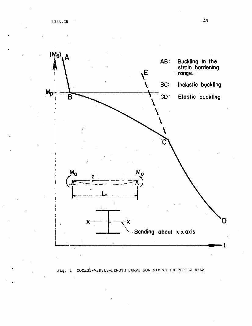
of beams. A typical length versus critical moment curve is shown in Fig. 1
for a simply supported steel wide-flange beam subjected to equal end
moments. This curve consists of the following three parts: (1) Portion
CD represents classical elastic buckling(l); (2) P0!"tion AB depicts the
buckling behavior of a very short member for which it can be assumed
that all fibers have been strained into the strain-hardening range(3) ,
and (3)portion BC of the curve corresponds to buckling in the inelastic
range. Buckling in this range takes place when some parts of the cross
section are yielded, while other parts are still elastic. The strain
hardening and the elastic curves are typical Euler hyperbolas which do
not intersect. The curve for inelastic buckling provides a transition
between these two extreme idealizations.
205A.28 -2
In the ensuing report a method will be presented for the determination
of the buckling strength in the inelastic range 0 The problem will be solved
for the case of a simply supported as-rolled steel wide-flange beam subjected
to equal end moments causing single curvature deformation, An analytically
"exact" solution will be developed for a given average residual stress
distribution. This solution will then be simplified for design application.
Finally, the results will be compared wi.th existing empirical approximations,
and a possible design modification will be discussed.
1.1 PREVIOUS WORK
Of the three types of problems shown in Fig, 1, the problem of elastic
lateral buckling has been investigated most thoroughly.* Solutions for the
lateral buckling of beams in the strain-hardening range have been developed
recently for structural steel wide-flange beams(3) and for rectangular
beams made of a metal having a monotonically increasing stress-strain
curve~4) Inelastic lateral buckling solutions for steel beams of rectan
gular(S) and wide-flange(6) shape containing no residual stresses are
available, In an unpublished report(7) the author has presented solutions
for the determination of the inelastic lateral=torsional buckling strength
of as-rolled wide-flange beam-columnso The following report is a summary
and an extension of that work in Ref. 7 which per~ains to the buckling of
beams, This work differs from previous solutions in the fact that the
reduction in beam stiffness due to early yielding caused by the residual
stresses is included in the calculations.
*A discussion of this work can be found in Refs. 1 and 2, These referencesinclude extensive listings of the pertinent literature,
205A.28
1.2 LATERAL BUCKLING IN THE INELASTIC RANGE
-3
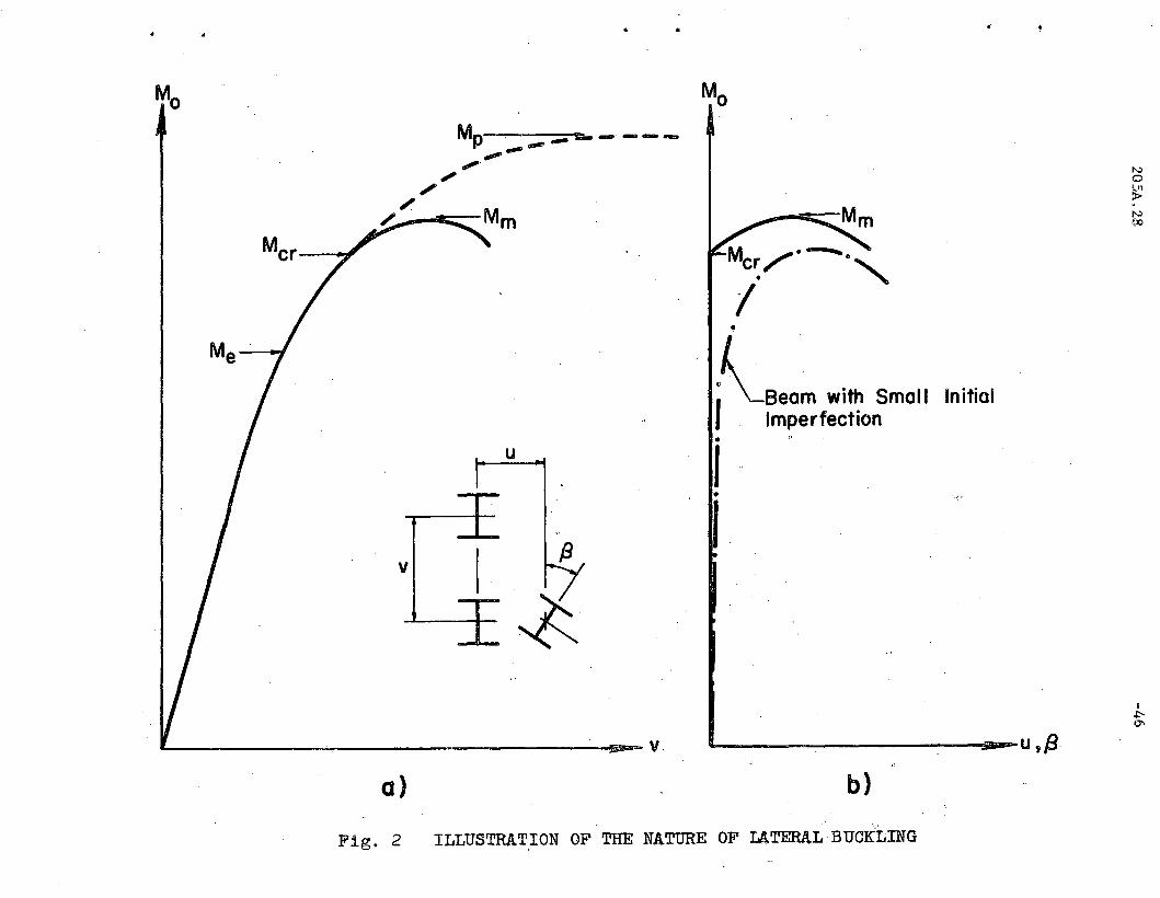
Schematic load-deflection curves for beams failing by lateral
buckling in the inelastic range are shown in Fig~ 2. The inset of Fig.
7a illustrates two possible deflection configurations into which any
interior cross section of the beam may be deformed: For the first of
these, . the only deformation is the transverse deflection v. The
beam is located directly below the undeflected cross section and in
. .
..
iO,
the plane of the applied moment. The second deflection configuration
represents the buckled shape of the cross section. The corresponding
deformations are the transverse deflection v, the lateral deflection u,
and the twist~. Bifurcation of the equilibrium takes place when the
cross section moves from its laterally undeflected deflection configura-
tion to an infinitely close buckled deformation
The curve in Fig. 2a shows the relationship between the applied
end moment Me and the transverse deflection v as Mo is increased from
zero to its maximum value Mm. If no lateral buckling were to occur,
the curve would increase monotonically until it would approach the fully
plastic moment ~ as an asymptote (dashed curve). However, at the critical
moment Mcr (where Mcr is above the elastic limit moment M~ for inelastic
buckling) bifurcation of the equilibrium takes place, and the deflection
curve deviates from its original course because of lateral buckling. The
beam wilt still be able to support a small increase of moment to ~, after
which rapid unloading indicates failure.
The relationship between M and the lateral deflection u or theo
tWisting angle ~ is illustrated in Fig. 2b. No lateral deflection or

•
rt
205A.28 -4
twist is present until the critical moment is reached. As the moment is
increased above Mcr ' these deformations will rapidly increase until Mm:and thus failure is reached. In the case of smal{ initial imperfections
lateral deformations u and 13 will exist from the start elf loading: (see dot-dash
curve in Fig. 2b),.'"
The computation of the maximum moment for perfectly straight beams
f b . th 11 i . i 1 . i' . , t l' d (2)or or eams W1 sma n1ta excentr1c t1es 15 qU1 e comp 1cate .
For this reason the moment causing initiation of -lateral buckling will
be used as a lower bound to the maximum moment. This moment is computed
on the basis that at buckling no previously yielded fibers will unload
elastically and that additional bending is resisted by the unyielded
elastic core of the member. The critical moment M corresponds to thecr
critical or "tangent modulus" load of axially loaded columns failing
in the inelastic range.(l) Just as the tangent modulus load is taken
as the critical load for axially loaded columns, here the moment causing
initiation of buckling is taken as the critical moment at which the
structural usefulness of the beam is exhausted. This assumption usually
results in only a small conservative error.

205A.28
II. D EVE LOP MEN T .0 F THE THE 0 R Y
11.1 ASSUMPTIONS
-5
'.
The following assumptions underlie the subsequent theoretical
derivation's:
(1) No external lateral forces are applied to the beam between supports,
(2) The beam is initially straight and fr~e of imperfections.
(3) The cross section retains its original shape during buckling
(that is, local buckling is assumed to be not critical(8»,
(4) The ends of the beam may not translate or twist; however they are
free to rotate ,laterally and the end sections are free to warp
("simply supported" end-condi tions (1) .
(5) The applied end bending moments are equal, causing single
curvature deformation about the strong axis of the beam (see
inset of Fig. 1).
(6) The beams are as-rolled, ASTM-A7 steel wide-flange shapes. The
idealized cross section is shown in Fig.·3 (fillets and variations
of the flange thickness are neglected).
(7) The cross sectional and material properties are uniform along
the whole length of the beam,
(8) The stress-strain diagram is as shown in Fig. 4, The material
properties are assumed to be uniform over 'the cross section. The
following standard values of these coefficients are used for
computational purposes:
(J y = 33 ksi

-.
205A.28 -6
E = 30,000 ksi
Est= 900 ksi(8)
G = 11 ,500 ksi
Gst= 2.,400 ksi(8)
(9) The assumed residual stress pattern is shown in Fig. 5~9)
These stresses are assumed constant across the thickness of
each cross section element. The stress ~rc is the maximum
compressive stress at the tips of the flanges, and rrrt is the
maximum tensile residual stress. Consideration of equilibrium
requires that the relationship between ~rc and ~rt be the
following: (9)
[bt orc 1
rrrt = bt + w(d-2t) J ..•. (1)
where b, t, w, and d are cross sectional dimensions defined
in Fig. 3. A maximum compressive residual stress of ~rc =
0.3O-y will be used for the numerical computations~9)
11.2 THE BUCKLING EQUATION
The equation representing the critical combination of length and
end moment for simply supported wide-flange beams under uniform moment
has been derived by Timoshenko.* This equation may be written in the
following form:
..
2(Mo)cr . . . • (2)
*The derivation is shown in Chapter V of Ref. 10. Timoshenko's derivationwas made specifically for elastic buckling. However, the process can beextended to include also inelastic buckling if the stiffnesses are in thegeneral terms of By, CT , Cw instead of the usual elastic expressions Ely,GKT and EIlJ
205A.28
wh2re
=7
(MQ)cr End moment at initiation of buckling
By = Bending stiffness about the y=axis
L = Length of the beam
= St. Venant torsional stiffness
Cw ::;: Warping stiffness.
Equation 2 is the characteristic value of the differential equations
of lateral buckling under pure moment for the following simply supported end
conditions:
u = at z = 0 and z = L
The coordinate z is measured from one end of the beam al~ng the deformed
centroidal axis (see inset in Fig. 1).
The stiffness coefficients By, Cr and C~l are equal to the
following expressions in the elastic range:
EI d2Y=4
• • . • • (3)
where I = Moment of inertia of the. wide- flange section about i t-s y.,.axisy
K.r = St. Venant torsion constant(ll)
I W '= Warping constant(ll)
d = Depth of the section (See.Fi~~ 3).
If buckling takes place after certain portions of the cross section have
already yielded, the expTessions of Eq. 3 for the stiffnesses need not hold

•205A.28 -8
true. Yielding reduces the stiffness of a member, and therefore the inelastic
values of By, CT' and Cw will not remain constant. They will vary with the
amount of yielding. The primary purpose of this report is to establish the
variations of the stiffnesses due to yielding, and then to solve Eq. 2 for
the values of the critical moments in the inelastic range.
The derivation of Eq. 2 implicity assumes the following two conditions:
(1) The stiffnesses may not vary along the length of the member, and (2) the
shear center must lie in the plane of bending (that is, the y-y plane). Since
the moment is uniform along the whole length of the beam, each cross section
is subjected to the same forces, and thus each cross section is yielded
identically. Therefore the stiffnesses do not vary along the z-axis. Further
more, yielding will be symmetrical about the y-y axis because of the symmetrical
residual stress pattern (see Fig. 5). As a consequence, the shear center
will remain on the y-y axis. Thus both conditions imposed by Eq. 2 are
fulfilled for a yielded wide-flange beam.
11.3 DETERMINATION OF THE ZONES OF YIELDING
In order to be able to compute the stiffnesses governing the
buckling equation in the inelastic range, the yielded pattern corresponding
to the applied bending moment must be known. The relationships between
the bending moment and the corresponding curvature and the yielded zones
are derived in Appendix A by a step-by-step procedure, starting from the
unloaded state and leading to successively more and more severe cases of
yielding. The process consists of finding the curvature and the bending
205A.28 -9
"
moment caused by given stress patterns. These stress-patterns (shown
in Figs. 6 to 11), as well as the yielded configurations, ar~ dependent
on the cross sectional geometry (Fig. 3) and on the initial residual stress
distribution (Fig. 5).
The equations expressing the relation between the moment M, the
curvature ¢, the compression flange yielding parameter CL (Figs. 7 and 8)
and the tension flange yielding parameterY(Figs. 9 and 10) are tabulated
at the end of Appendix A. Several sample derivations are given at the
beginning of this appendix to illustrate how the equations are developed
from the equilibrium conditions.
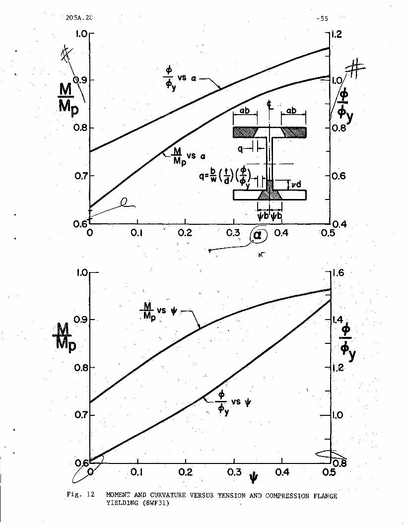
The results of the computations are. shown in ,Fig ..12 for the
8WF3l section. The curves in the upper portion of this figure show the
variation of the moment and the curvature with compression flange yielding
CL, whereas the curves in the lower half of Fig. 12 give the relationship
betwe8u M, ¢, and the tension flange yielding parameter'~
With the aid of Fig. 12 it is thus possible to determine the
extent of yielding corresponding to any moment. (See inset in Fig. 12.)*
11.4 SIIFFNESSES OF THE YIELDED CROSS SECTION
In the previous section it was shown how the yield-pattern of a
wide-flange cross section corresponding to a given moment can be obtained.
* Web yielding Vd can be determined from equations given in Appendix A.Since the web contributes little to the lateral stiffness of the crosssection, no M vs,) curves are shown.
•205A,28 -10
The yielded configuration of the section is shown in the inset of Fig, 12,
From this sketch it may be observed that yielding (cross~hatched area) is
synnnetrical about the y-y axis, and that the interface between the elastic
and the plastic portions of the flange is inclined across the fl~nge
thickness, In order to simplify subsequent calculations this inclination
is neglected; the simpler yield pattern is shown in Fig, 13. The compression
flange is assumed yielded uniformly a distance ~b from the toes of the
flange, and the tension flange is yielded a distance 1ft' b from the center.
Since this simplification reduces the elastic core by a small amount, the
foregoing assumption is conservative,
In the derivations of Appendix A it was stipulated that the
stresses may nowhere exceed the yield stress a y .* As a consequence the
strains in the plastic sections lie on the flat portion o~ the stress-strain
d.i.d.gram, where the modulus of elastici ty is equal to zero. Since the
bending stiffness By and the warping stiffness Cw are d~pendent on the
modulus of elasticity (Eq. 3), only the elastic core can be assumed to
furnish those stiffnesses. It has been shown(5) that at the start of
lateral buckling St, Venantis torsional stiffness CT is not dependent on
the amount of yielding, and therefore the full elastic value of CT = GKT
can be used for substitution in the lateral buckling equation, Thus only
the stiffnesses By and Cw need be computed for the unyielded core of the
wide-flange cross section.
* A proof that this assumption is correct can be seen from Fig, 12, wherethe maximum curvature when both flanges are fully yielded is equal to1,52 0y ' This curvature is considerably below the curvature at thestart of strain hardening ( 0st ~ 12 0/3», and thus the yieldedportions can be assumed to have no resistance to additional bending.

205A.28
Bending Stiffness By.
-11
The bending stiffness of the elastic core about the y axis is
equal to (See Fig. 13):
A rearrangement of this expresssion yields the following equation for By:
. • • • . (4)
where I is the moment of inertia qf the original unyie1ded seGtion.y
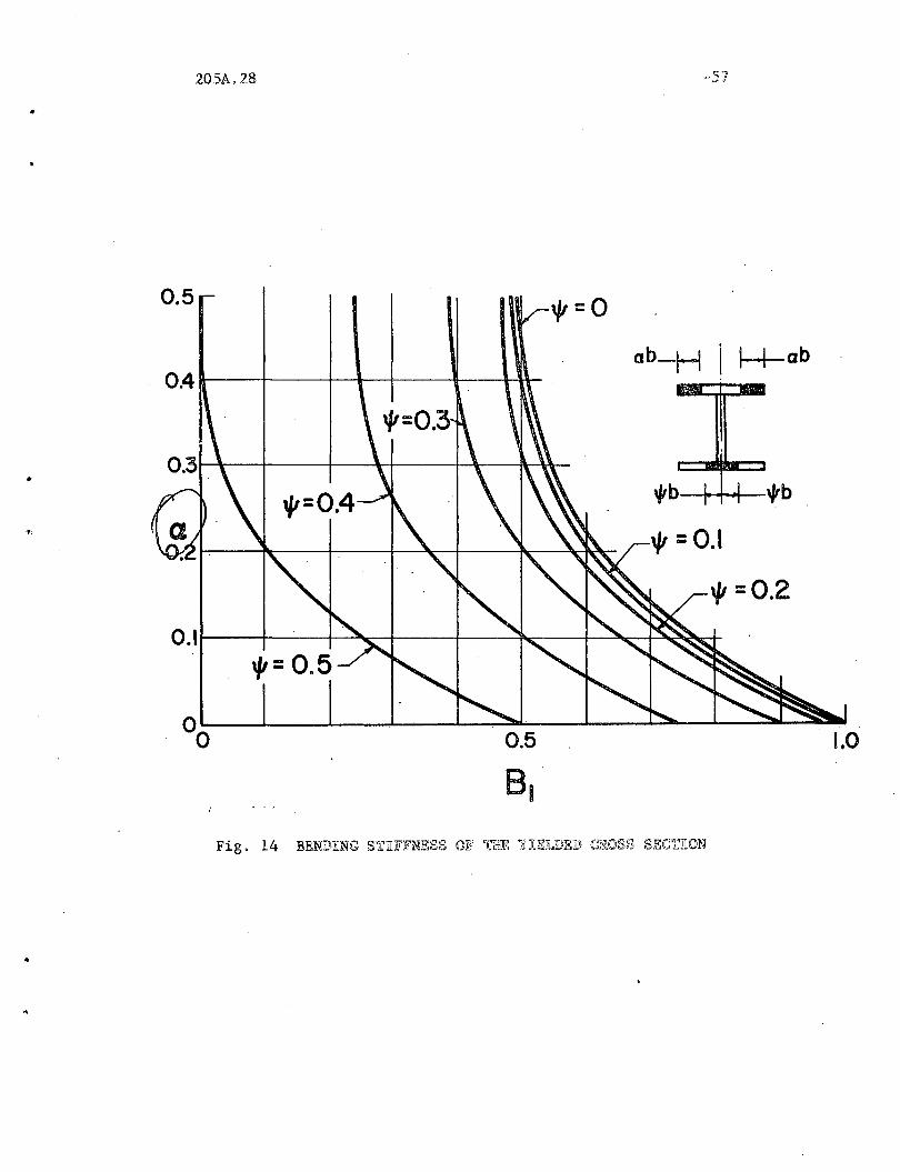
(Iy = b3t ). and B1 is a reduction factor which is equal to6
This relationship between~. ~. and B1 is i11ustrate~ in Fig. 14.
When the section is fully elastic ( ~ = r = 0). B1 ~ 1.0. and when
~ = r =0.5 (full yielding of the. flanges). B1 =O.
Warping Stiffness CWo
. (5)
The warping stiffness of a section with unequal flanges has been
det~rmined (Eq. 231. Ref. 1) as
. • . . • (6)
205A.28 -12
where 11
is the moment of inertia of the compression flange about the
y-axis, and 1 2 is the corresponding property of the tension flange. From
Fig. 13 it is seen that
3(1-20.) · . . . . (7)
· . . . . (8)
Substitution of Eqso 7 and 8 into Eq. 6 gives the following expression
for the warping rigidity:
· . . . . (9)
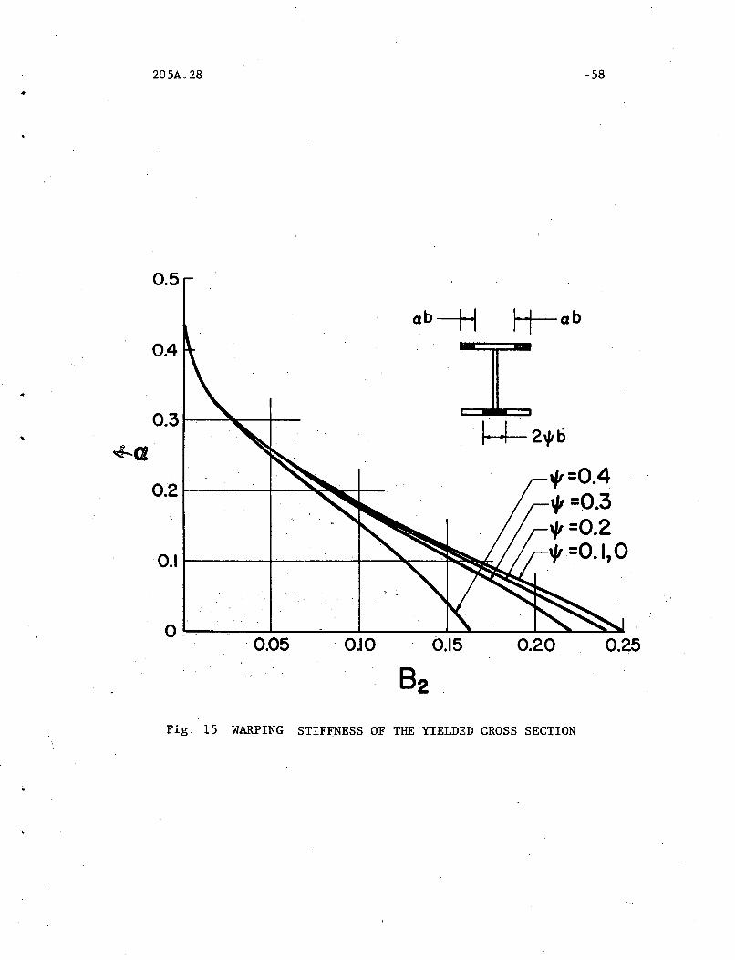
where I is the moment of inertia of the original section, and B2 is ay
reduction factor equal to
=
1/r3 3(1-8 L ) (1-20.). . . . (10)
The curves relating a., y and B are shown in Fig. 15. At a. =If = 0,2
B2 = 0.25, thus fulfilling the fully elastic boundary condition. At a. = 0.5)
that is when the compression flange is fully yielded, Bi = 0 for any
value of -r This means that when the effective s~ction is aT-section,
the warping rigidity is zero.(l)
.-
. '
205A.28 -13
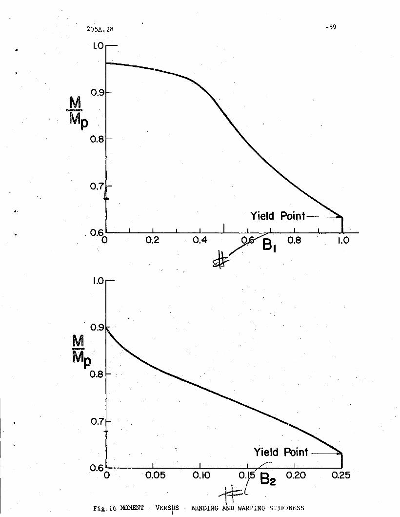
The curves in Figs. 14 and 15 permit the determination of the
stiffnesses By and Cw when ~ and¥i are known. In subsequent calculations
it is desirable to have a direct relationship between the moment and the
stiffness coefficients Bl and B2 . This may be accomplished by eliminating
~ and T with the aid of Fig. i2, where the moment versus ~ and ycurves are shown. The resulting curves for the 8WF3l section are given
in Fig. 16, where moment is plotted directly against Bl and B2 . Thus if
M is known, the corresponding stiffnesses By and Cw can be immediately
determined from this figure and from Eqs. 4 and 9.
11.5 THE INELASTIC BUCKLING CURVE.
The equation of buckling (Eq. 2) can be rearranged in the following
manner:
2 4(M) L <.
""'0 cr2 C L2 .... 4 C B = 0
T( By T - JL W Y
If this equation is divided by ~2 = Z2 uyZ (where Z is the plastic
modulus) and by r y4 (where r y is the weak axis radius of gyration of the
original cross section), and if the expressions for B ,C and Carey T w
substituted from Eqs. 4, 3c and 9, the buckling equation can be written
in the following non-dimensional form:
l(~rJ ~~)4_~'::i )(7) Bl} (r~ j_.
_[(~2Er . (11)
205A.28 -14
Equation 11 is a fourth order equation in that slenderness ratio
L/ry which corresponds to the critical moment at which lateral buckling
commences. The coefficients of L/r consist of the cross sectional cony
stants AKT
Z2and (where A is the cross sectional area of
the original section), the material constants2. 2
and ( 11 E ).cry
the non-dimensional bending moment Mo/~' and the coefficients Bl and B2
which are directly dependent on the moment.
The con~truction of the critical length-versus-moment curve of
Fig. 1 can be performed in the following manner: For a given wide-flange
cross section first the moment versus Bl and B2 ~urves are developed (as
shown- in Fig. 16 for the 8WF3l section). Next,Eq. 11 is solved for
L/ry for assumed values of the moment. This is done for a sufficient
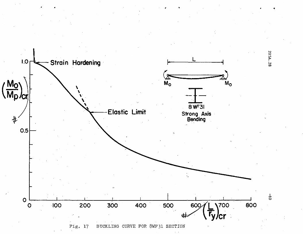
number of moment values until the whole course of the buckling curve is
established. Figure 17 shows such a curve for the 8WF3l section. For
moments from 0 to 0.631 ~ elastic buckling governs. In this region the
stiffnesses By and Cw are undiminished. For a moment larger than 0.631 ~,
yielding takes place due to the presence of residual stresses before the
section buckles. Points on this portion of the curve are computed by
assuming a moment (Mo > 0.63 Mp)' finding the values of Bl and B2 corres
ponding to this moment from Fig. 16, and solving Eq. 11 for the critical
weak axis slenderness ratio. The increments of moment used for the
inelastic part of the curve in Fig. 17 were chosen at 0.05 M .P
The cut-off point for the start of strain hardening (at
L/ry = 20 in Fig. 17) is computed by a method suggested
2 is solved by setting BY
G K and Cw =st T
in Ref. 3. Equation2
Estlyd ,where4
205A.28 -15
Est and Gst are strain hardening moduli. It has been shown(20) that this
poinsat which the whole section can be assumed to be strain hardened at buckling,
occurs at a slenderness ratio of about 20 for all rolled wide-flange
sections.
The curve in Fig. 17 describes the buckling behavior of an 8WF3l
section over its whole length range. Inelastic buckling governs up to a
length of about 220 r , or to about 37 feet. Thus it can be seen thaty
for practical lengths one must consider the reduction in buckling strength
due to yielding.
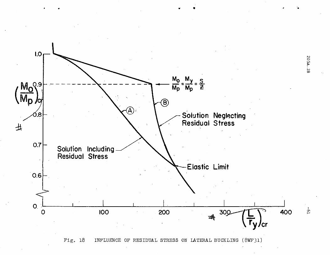
The error involved in assuming that yielding does not start
until the yield moment MY = s cry (where S is the section modulus) is
reached is illustrated in Fig. 18. In this figure curve A represents the
inelastic solution including residual stresses, and curve B is a
continuation of the elastic Euler hyperbola until (M) = M. A straighto cr y
line transition has been used from the yield moment to (Ma)cr = MP at
the start of strain hardening. It can be seen that the residual stresses
have a considerable influence on the buckling strength, and that their
neglect may lead to results which may be as much as 30% unconservative.
The usual design procedure which does not permit the use of
moments larger than the yield moment is shown by the dashed horizontal
line in Fig. 18. One can note that for L/ry >90 this rule leads to
unconservative answers, whereas in the range of 0 < L/ry < 90 the full
strength of the beam is not utilized.
205A.28
III. S IMP L I FIe A T ION
PRO C E D U R E
o F THE
-16
..
A method has been presented for the determination of the buckling
curves for wide-flange beams failing by inelastic lateral buckling.
Numerical results are shown for the 8WF3l section in Fig. 16. Additional
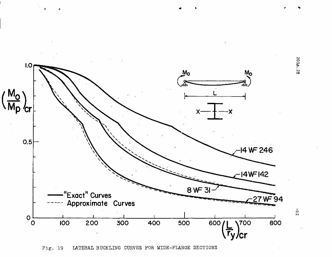
calculations by the same procedure were made for the 27WF96, the l4WF142
and the l4WF246 section. The results of the calculations are shown as the
solid line curves in Fig. 19.
This method of computing the inelastic lateral buckling strength
has one serious shortcoming: the computational work is too laborious. The
main reason for this is the complex geometry of the stress patterns result-
ing from the cross sectional shape of the wide-flange section and the
residual stress existing before load application.
A simplification of the calculations may be achieved as follows:
In Fig. 20 are shown the reduction curves for the four sections for which
computations were made (27WF94, 8WF3l, l4WF142, l4WF246). In the upper"
portion of the figure the M/~ versus B1 relationship is given, while in
the lower half the curves for M/~ versus B2 are shown. It can be observed
from this figure that for even these geometrically dissimilar wide-flange
sections the range in which these curves lie is not very great. Therefore
no great error will result if one average curve is used for any wide-flange
section. These approximate average curves are shown as heavy solid lines
in Fig. 20 .
The use of these average curves for Bl and B2 simplify the
205A.28 ~17
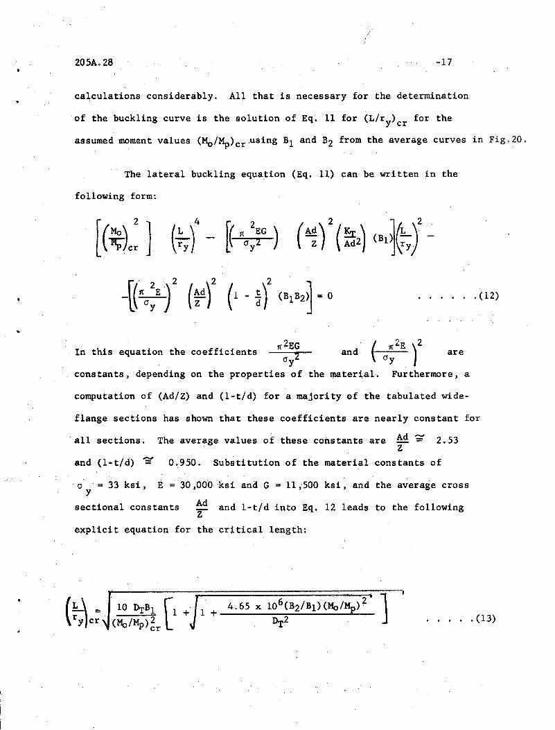
ca~culations considerably. Al~ that is necessary for the determination
of the buckling curve is the solution of Eq. 11 for (L/ry) cr for the
assumed moment values (MO/Mp)cr,using Bl and B2 from the average curves in Fig.20.
The lateral buckling equation (Eq. 11) ~an be Written in the
following form:
I~ this equation the coefficients
..
constants, depending
1{2EG, 20y
on the properties of
and ~ 0;2E )2 are
the ~terial. Furthermore, a
.(12)
computation of (Ad/Z) and (l-t/d) for a majority of the tabulated wide-
flange sections has shown that these coefficients are nearly constan~ for
'all sections. The average values of these constants are ~ ~ 2.53Z
and (l-t/d) =- 0.950. Substitution of the material constants of
0 = 33 ksi, E ='30,000 ksi and G = 11 ,500 ksi, ~nd the average crossy
sectional constants Ad and l~t/d into Eq. 12 leads to the followingZ
explicit equation for the cr~tica1 length:
•. . . . . (13)
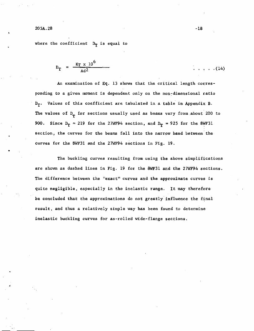
205A.28 -18
where the coefficient Dr is equal to
=
6KT x 10. ~ .. (14)
•
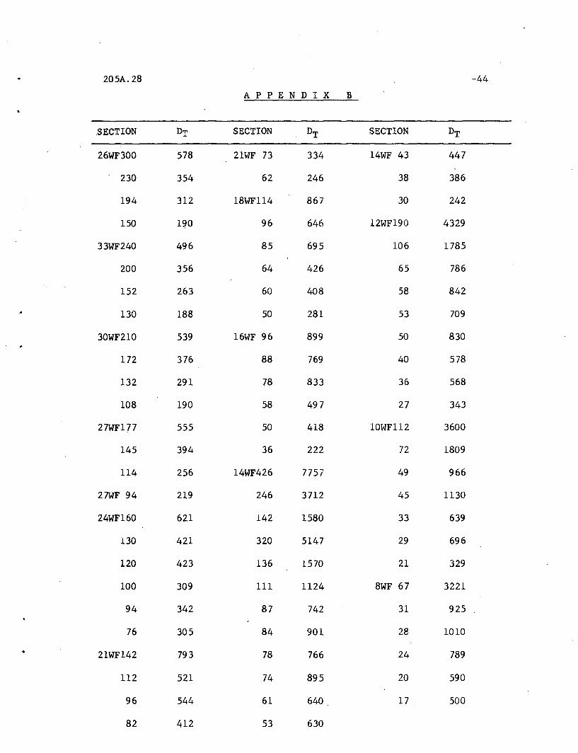
An examination of Eq. 13 shows that the critical length cox::res-
ponding to a given moment is dependent only on the non-dimensional ratio
DT. Values of this coefficient are tabulated in a table in Appendix B.
The values of DT
for sections usually used as beams vary from.about 200 to
900. Since DT = 219 for the 27WF94 section, and DT = 925 for the 8WF3l
section, the curves for the beams fall into the narrow band between the
curves for the 8WF3l and the 27WF94 sections in Fig. 19 •
The buckling curves resulting from using the above simplifications
are shown as dashed lines in Fig. 19 for the 8WF3l and the 27WF94 sections.
The difference between the "exact" curves and the approximate curves is
quite negligible, especially in the inelastic range. It may therefore
be concluded that the approximations do not greatly influence the final
result, and thus a relatively simple way has been found to determine
inelastic buckling curves for as-rolled wide-flange sections.
205A.28
IV. COM PAR ISO N WIT H DES I G N
-19
A P PRO X I MAT ION S
The fact that the buckling strength of beams is reduced due to
yielding before the theoretical yield moment My is reached has been known
for some time.(12) Because no direct computation of the reduction has
•
been available, empirical design approximations have been suggested for
the computation of the critical moment in the inelastic range. These
approximations can be grouped into two categories: One of these methods
is to provide an empirically determined transition curve between the
elastic Euler hyperbola and an allowable maximum moment at zero length.
The other method consists of computing the critical moment by the elastic
formulas, and then to r'educe this "ideal II moment in accordance wi th an
empirically determined reduction curve to an lIa 110wab1e" moment. The
first approach has been used extensively in this country(l2), and the
latter is the basis of the German buckling specifications.(13)
In the following one of each of the above discussed procedures
will be compared with the "exact" theory of this report.
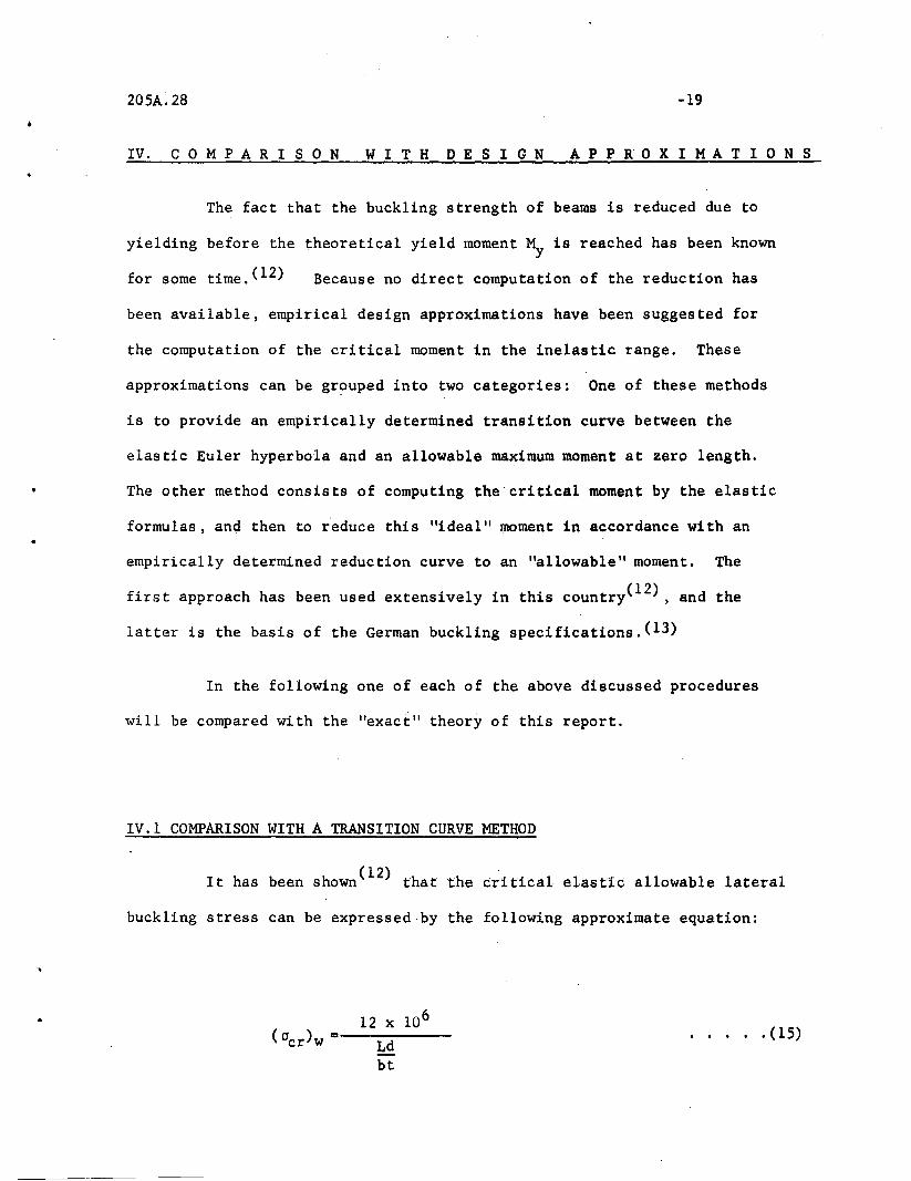
IV.1 COMPARISON WITH A TRANSITION CURVE METHOD
It has been shown (12) that the critical elast'ic allowable lateral
buckling stress can be expressed by the following approximate equation:
12 x 106
(crcr)w =--L-d---
bt
..... (15)
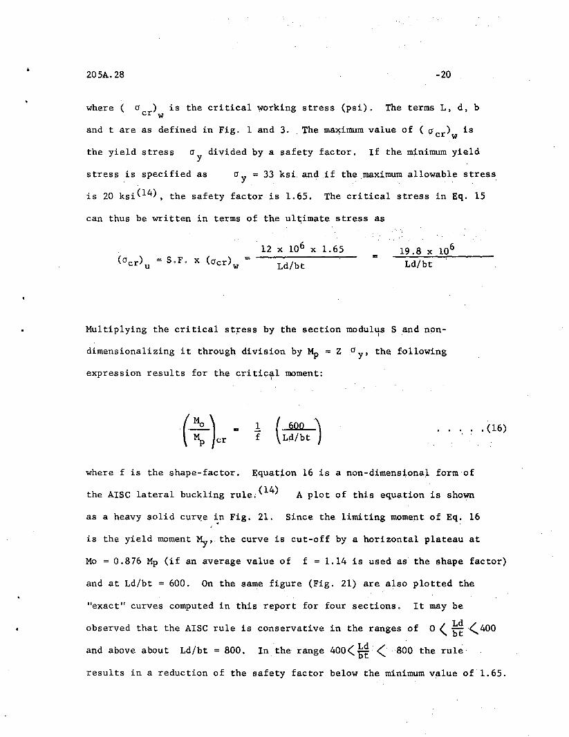
20sA.28
where ( o ) is the critical working stress (psi).cr w
-20
The terms L, d, b
and t are as defined in Fig. 1 and 3. !he ma~imum value of ( 0cr)w is
the yield stress 0y divided by a safety factor. If the minimum yield
stress is specified as o y = 33 ksi. and .if the maximum allowable stress
is 20 ksi(14), the safety factor is 1.65. The critical stress in Eq. 15
can thus be written in terms of the ul~imate stress as
=12 x 106 x 1.65
Ld/bt= 19.8 x 10⁶
Ld/bt
Multiplying the critical st~ess by the section modul"ts S .and non-
dimensionalizing it through division by Mp = Z 0 y' the following
expression results for the critic~l moment:
1f (
600 )Ld/bt
" . . (16)
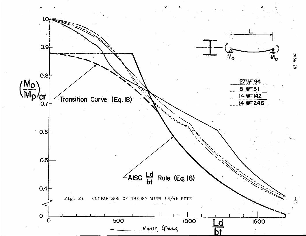
where f is the shape-factor. Equat~on 16 is a non-dimens~onal form of
the AISC lateral buckling rule;(14) A plot of this equation is shown
as a heavy solid cur~e ~n Fig. 21. Since the limiting moment of Eq. 16
is the yield moment My, the curve is cut-off by a horizontal plateau at
Mo = 0.876 Mp (if an average value of f = 1.14 is used as the shape factor)
and at Ld/bt = 600. On the same figure (Fig. 21) are also plotted the
"exact" curves computed in this report for four sections. It may be
observed that the AISC rule is conservative in the ranges of 0 ( ~~~400
and above about Ld/bt = 800. In the range 400(~ (800 the rule
results in a reduction of the safety factor below the minimum value of 1.65.
205A.28 -21
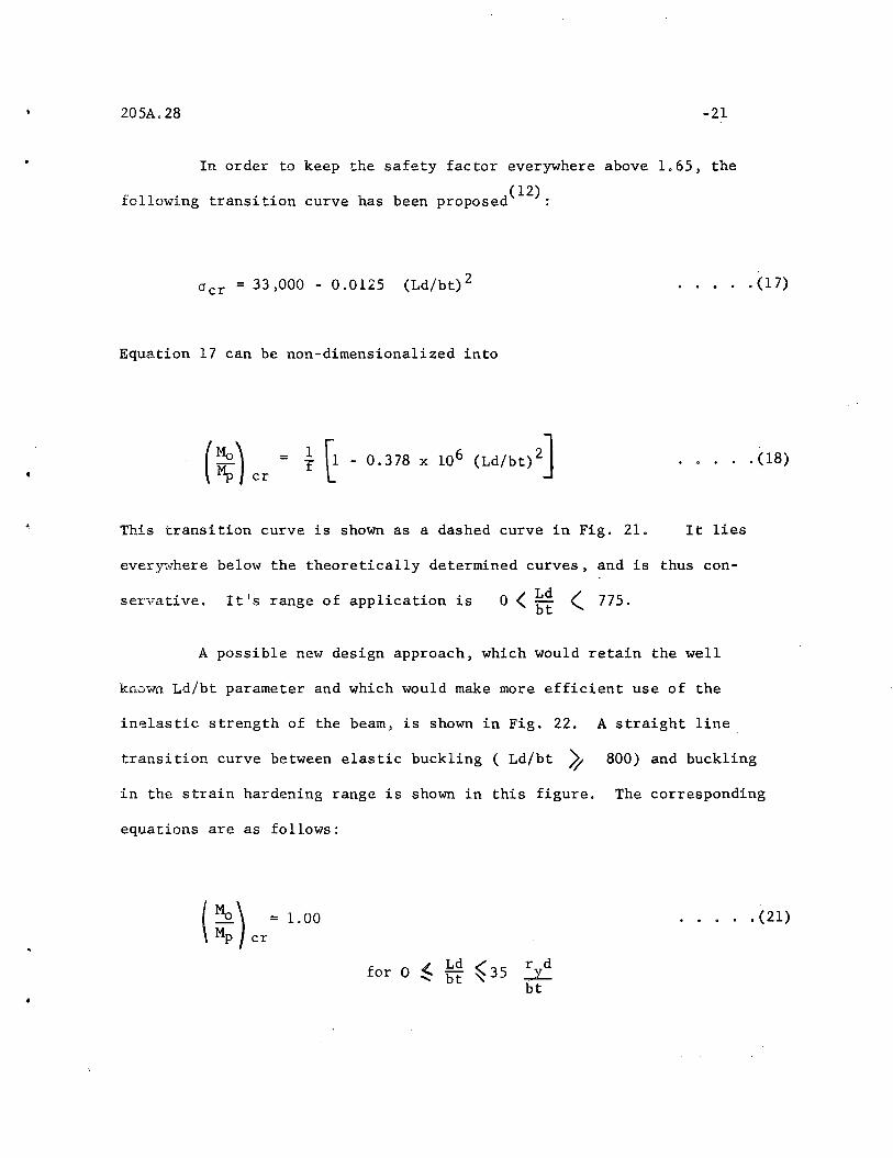
In order to keep the safety factor everywhere above 1.65, the
( 12)following transition curve has been proposed :
acr = 33,000 - 0.0125 (Ld/bt)2
Equation 17 can be non-dimensiona1ized into
(~) cr • } ~ - 0.378 x 10⁶
(Ld/bt)2]
This transition curve is shown as a dashed curve in Fig. 21.
· . • . . (17)
· . . . . (18)
It lies
ever~vhere below the theoretically determined curves, and is thus con-
servative. It's range of application is <Ld (a bt 775.
A possible new design approach, which would retain the well
known Ld/bt parameter and which would make more efficient use of the
inelastic strength of the beam, is shown in Fig. 22. A straight line
transition curve between elastic buckling (Ld/bt ~ 800) and buckling
in the strain hardening range is shown in this figure. The corresponding
equations are as follows:
1.00
-' Ld./ r dfor 0 ~ bt ~35 ...:L
bt
· • . . . (21)

l~ Ld
0.342 bt ": 35
20SA.28
( Mo) - 1.000 _Mp c; 800 - 35
~Jryd
bt
-22
..... (22)
..... (22)
for
526Ld/bt
:cor
35 ryd ..; Ld (' 800bt ~. bt ~
800 " Ld <00" bt "
. ~ .. ; (23)
Equation ~l repre~ents the lateral bracing spac~ng rule used in .plastic
design(18), which states that 'in the vicinity of a plastic hinge (that
is Mo = Mp), the critical length for uniform moment is equal to 35 r y .*(Since the non-dimensional length parameter used is Ld/bt, the slender-
ness ratio =Ld
btx
bt
dry) . Equation 23 is the AISC Ld/bt rule,
which governs elastic instability (see Eq. 16, wq.ere the shape factor is
set equal to 1.14). Equation 22 represents the straight line transition
between the end points of Eq. 21 and 23. In Fig. 22 the curves of
these three equations are compared with the "exact,II solutions for four
cross sections. It is seen t,hat the proposed curves utilize th~ inelastic
strength of the beam, .while at the same time they repres~nta safe lower
bound.
------~--~----~----------------------------
* This rule has been shown to be correct by theoretical and experim~ntal
means.(3)(19)
205A.28
IV.2 COMPARISON WITH A REDUCTION CURVE METHOD
-23
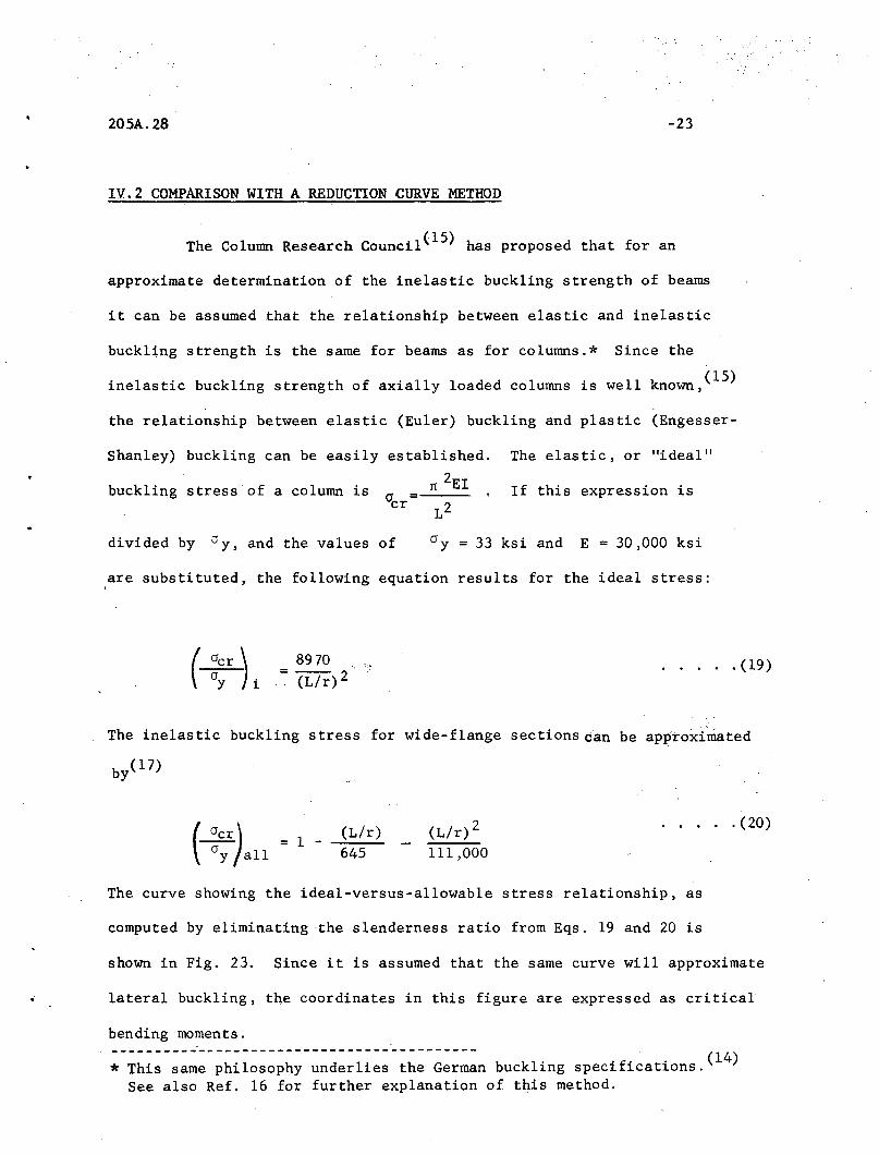
The Column Research Council(15) has proposed that for an
approximate determination of the inelastic buckling strength of beams
it can be assumed that the relationship between elastic and inelastic
buckling strength is the same for beams as for columns.* Since the
inelastic buckling strength of axially loaded columns is well known,(15)
the relationship between elastic (Euler) buckling and plastic (Engesser-
Shanley) buckling can be easily established. The elastic, or "ideal"
1C 2EIbuckling stress of a column is If this expression isO'cr =
L2
divided by v y , and the values of 33 ksi and E = 30,000 ksi
are substituted, the following equation results for the ideal stress:
8970=-- 2.. (L/r)
. . . . . (19)
The inelastic buckling stress for wide-flange sections can be approxi~ted
(ocr)--a; all = 1 -
(L/r)645
(L/r)2111,000
. . . . . (20)
The curve showing the ideal-versus-allowable stress relationship, as
computed by eliminating the slenderness ratio from Eqs. 19 and 20 is
shown in Fig. 23. Since it is assumed that the same curve will approximate
lateral buckling, the coordinates in this figure are expressed as critical
bending moments.------------------------------------------
d 1 , h b kl' 'f" (14)* This same philosophy un er ~es t e German uc ~ng speC1 ~cat~ons,
See also Ref. 16 for further explanation of this method.

205A,28 -24
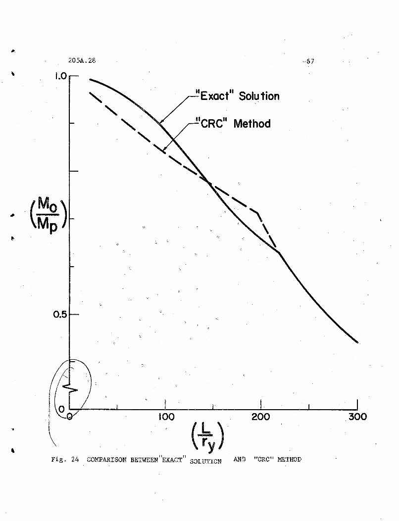
The lateral buckling strengths of a beam can be thus approximated
by calculating the elastic critical moment (by keeping Bl = 1,0 and B2 = 0,25
in Eq, 11), and then entering the reduction curve of Fig, 22 and directly
reading off the inelastic "allowable" moment.* The results of the computa-
tions for the 8WF3l section are shown in Fig. 24, where the approximate
curve is dra~~ as a dashed line. The comparison is fair, with a maximum
deviation being about 5%.
* This method is especia.lly useful for cases where the end conditionsof the beam are not simple and where the beam, is subjected to lateralloads or a moment gradient. Elastic solutions are available for thesecases(16) , wherea.s the computation of "exact" inela.stic solutions seemstoo difficult at this time.
•
205A.28 -25
v. CON C L U S ION S
In this report a method has been presented for the determination
of the inelastic buckling strength of steel wide-flange beams failing by
lateral buckling. The method has been illustrated for the case of wide
flange beams because o.f their frequent occurrence in civil engineering
structures, The type of solution, however, may be adapted for any cross
sectional shape under any residual stress distribution, provided that
bending takes place in a plane of symmetry, and that the residual stresses
are also symmetrical about the plane of bending. A further stipulation
is that bending is uniform and that the stress-strain diagram can be
approxi~ted by straight lines.
An extension of this work would be to compute the lateral buckling
strength of beams subjected to unequal bending moments or to loads placed
between the supports. In this case the moment, and thus the distribution
of yielding along the length of the beam, is non-uniform. The best way
of obtaining a solution would be to solve the differential equations of
lateral buckling by the method of finite differences, possibly with the
aid of a digital computer. The stiffness reduction curves of Fig. 20 can
b~ utilized in these calculations.
The critical length versus end moment curves for a given wide
flange section are obtained in the following manner:
(1) The yielded zones corresponding to a given inelastic moment
are determined with the aid of the conditions of equilibrium.
General equations are given in Appendix A, and the curves

205A.28 -26
relating compression flange and tension flange yielding
corresponding to various moments are shown in Fig. 12
for the 8WF31 shape.
(2) The weak axis bending stiffness By and the warping stiffness
Cw for the "effective" reduced section are computed by Eqs.4
and 5 and Eqs. 9 and 10, respectively. Curves showing the
reduction coeff:i.dents Bl and B2 are shown in Fig. 16 for
the 8WF31 section, The St. Venantis torsional stiffness is
not reduced due to yielding. (5)
(3) The lateral buckling equation (Eq. 11) is solved for the
critical length for va.rious assumed values of the inelastic
moment and the corresponding reduced stiffness. The result
ing curve for the 8WF3l section is shown in Fig. 17.
A simplification of this procedure can be accomplished by noting
that the moment versus stiffness reduction coefficients B1 and BZ are
nearly the same for all wide-flange sections, (see Fig. ZO) and that
certain non-dimensional cross sectional properties can be assumed to
v~ry only a small amount for the tabulated rolled wide-flange shapes.
The critical length corresponding to any inelastic moment can be expressed
byEq. 13.
•
205A.28 -27
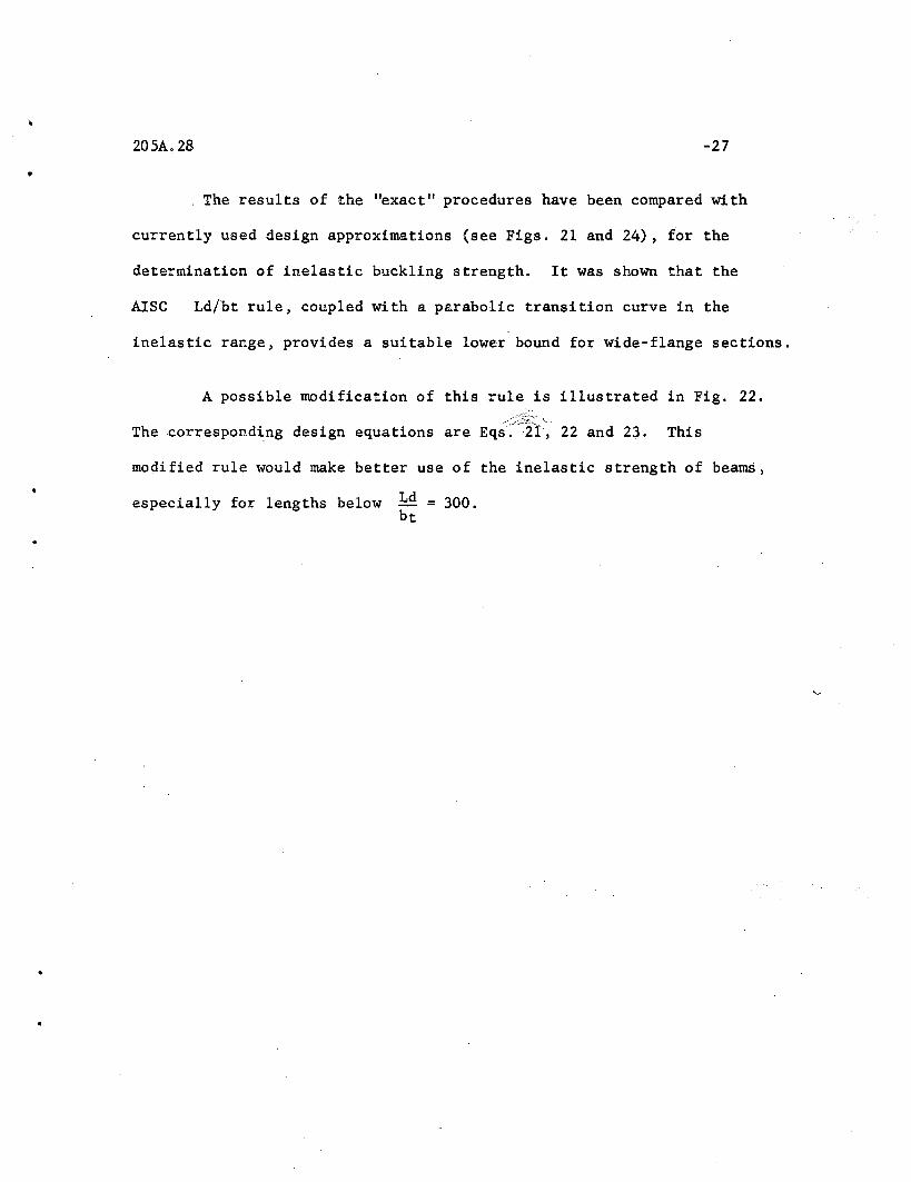
. The results of the "exact" procedures have been compared with
currently used design approximations (see Figs. 21 and 24) , for the
determination of inelastic buckling strength. It was shown that the
AISC Ld/bt rule, coupled with a parabolic transition curve in the
inelastic range, provides a suitable lower bound for wide-flange sections.
A possible modification of this rule is illustrated in Fig. 22.
The corresponding design equations are Eq;:~Iil~ 22 and 23. This
modified rule would make better use of the inelastic strength of beams,
..
especially for lengths below Ld = 300.bt
•
205A,28 -28
VI, A C K NOW LED GEM E N T S
This study is part of the general investigation 'Welded
Continuous Frames and Their Components" currently being carried out
at the Fritz Engineering Laboratory of the Civil Engineering Depart
ment of Lehigh University under the general direction of Lynn S, Beedle,
The investigation is sponsored jointly by the Welding Research Council
and the Department of the Navy, with funds furnished by the American
Iron and Steel Institute, American Institute of Steel Construction,
Office of Naval Research, Bureau of Ships and Bureau of Yards and
Docks,
The author expresses his thanks to Robert L. Ketter and Tadao
Kusuda for their helpful suggestions,
= St. Venan.t
'.
•
205A.28
A
E
G
Y'T
L
MID.
(Mc,)cr
s
z
1',U,W
-29
VII. NOM ENe L A T U R E
a Cross sectional area (in. 2)
= Stiffness reduction coeffi.cients
= Weak axis bending stiffness (lb. -in. 2)
torsional stiffness (lb.-in.2
)
= Warping sti.ffness (lb.-in. 4)
::: Cross sectiOi~.al. coefficient defined by Eq. 14
= Modulus of e:lasticity (psi)
Strain harcening modulus (psi)
Shear modulus (psi)
= Shear WJdulus in the strain hardening range (psi)
= Moment of inertia about the y-y axis (in. 4)
::: Effective momenta of inertia of the compression flange and thetension flange, respectively. (in. 4)
= Warping coefficient (in. 6)
= Torsion coefficient (in. 4)
= Unsupported length of the beam (in.)
= Critical length (in.)
= Applied end bending moment (in.-lbs.)
= Ultimate moment, (in.-lbso)
= Critical end moment (in.-lbs.)
= Plastic moment (ino-lbs.)
= Yield moment (in.-lbs.)
Section IDI:lduhlS (in. 3 )
Plastic modul~s (in. 3)
= Non-·dimensional coefficients defin,ed by Eqs 0 A-8, A-13 and A-ll,respectively
• 205A.28
b =Width of flange (in.)
d = Depth of beam (in.)
f = Shape factor
r = Weak axis radius of gyration (in.)y
t = Thickness of flange (in.)
u = Lateral deflection (in.)
v = Transverse deflection (in.)
w = Thickness of web (in.)
~b = Compression flange yielding (in.)
~ = Angle of twist
-30
..= Curvature, curvature at the yield point, curvature at the
onset of strain hardening, respectively.
..
~ = Tension flange yielding (in.)
,) d, L d = Web yielding (in.)
~_ ~ = Compression and tension flange stresses, respectively (psi)l"lT' MB
= Yield stress (psi)
= Maximum compressive and tensile residual stresses, respectively (psi). CTrc,CTrt
...C& = Cri tical s tress (psi)

205A.28
APPENDIX A
-31
The relationship between the applied bending moment and the resulting
curvature and yield patterns are developed below by a step-by-step procedure.
a) The Unloaded S t.e~te
In the unloadod state only the residual stresses are present on the
cross section. Their magnitude and distribution is shown in Fig. 5.
b) Elastic Behavior
Figure 6 shows the stresses on the three components of the cross section
(the compression flange, the web, and the tension flange). In this figure
arMT and ClMB are the absolute values of the maximum top or compression
flange stress and the bottom or tension flange stress, respectively. The
angle 0 is the curvature of the section in the plane of the web. Strains
are assumed proportional to the distance from the neutral axis.
If the forces in each of these parts due to the stresses are summed
and equated to zero, it is found that
(A-l)
The summation of the moments about the center of the section due to the
assumed stress dilstribution gives
M = (J SMT
(A-2)
where M is the moment applied to the section and S is the section modulus.
Because it will be more convenient to work with non-dimensional
ratios, both sides of equB\\tion A-2 will be divided by ~ = (J yZ, where

20SA.28 -32
M is the fully plastic moment, and Z is the plastic modulus. Thus, thep
non-dimensional form of Eq, A-2 is
M(A-3)
where f = zis is the shape factor of the cross section.
The curvature ¢ is obtained by geometry from Fig, 6.
tan E0 "';f E0d
2 a MT
d(A-4)
If .the yield stress cry is used in Eq, A-4, the Ilinitial yield curvature"
E0y is obtained. Therefore
(A-S)
and
The limit of elastic behavior is reached when
a >a (see Eq. 1), yielding will first commencerc rt
a +a = aMB rt y
elastic range, and
whichever occurs first, Since
(A-6)
a + a = a orMT rc y
aMT = a in theMB
in the compression flange, Thus
(;)= 1 _ ~cel.lim,
Using the abbreviation
(A-7)
•205A.28
T = 1 -
-33
(A-8)
the values of the moment and the curvature at the commencement of yielding
are:
(A-9)
,
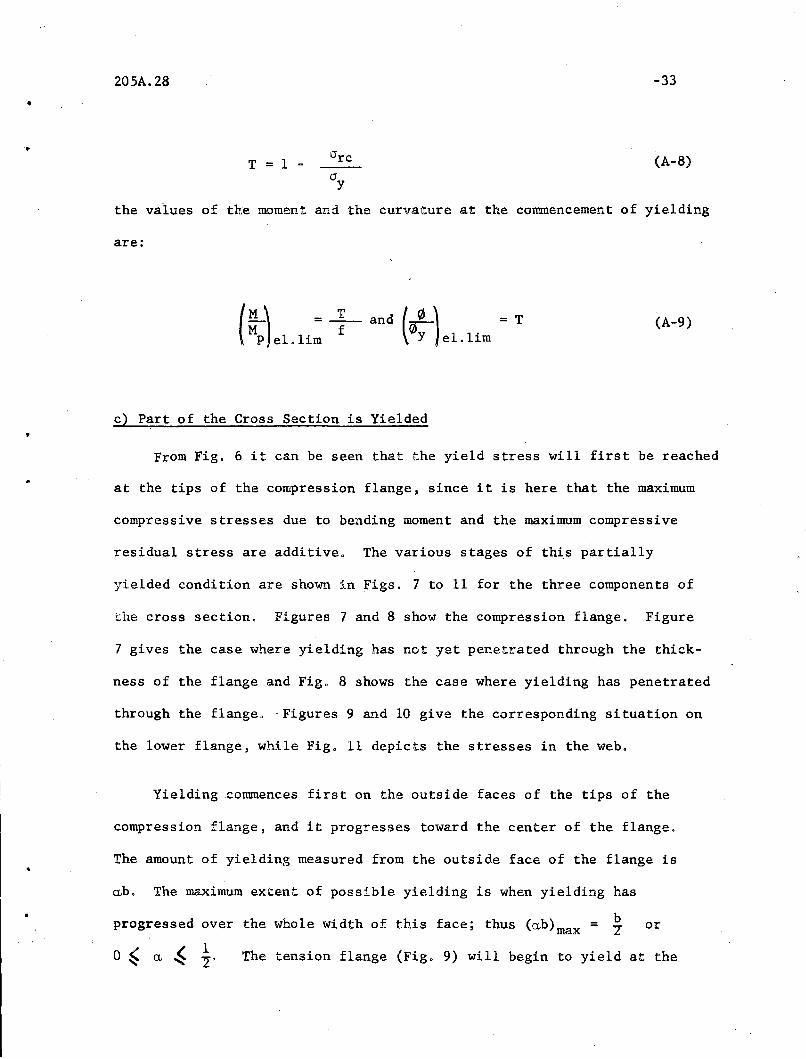
c) Part of the Cross Section is Yielded
From Fig. 6 it can be seen that the yield stress will first be reached
at the tips of the compression flange, since it is here that the maximum
compressive stresses due to bending moment and the maximum compressive
residual stress are additive. The various stages of th~s partially
yielded condition are shown in Figs. 7 to 11 for the three components of
the cross section. Figures 7 and 8 show the compression flange. Figure
7 gives the case where yielding has not yet penetrated through the thick-
ness of the flange and Fig. 8 shows the case where yielding has penetrated
through the flange. -Figures 9 and 10 give the corresponding situation on
the lower flange, while Fig. 11 depicts the stresses in the web.
Yielding commences first on the outside faces of the tips of the
compression flange, and it progresses toward the center of the flange.
The amount of yielding measured from the outside face of the flange is
~b. The maximum extent of possible yielding is when yielding has
bprogressed over the whole width of this face; thus (~b)max = 7 or
1-,:. The tension flange (Fig. 9) will begin to yield at the

205A.28 -34
center of the flange~ and yielding will progress toward the tips. The
amount of yielding in this flange is designated as rb (see Figs.
9 and 10) and therefore 12
From Figs. 7 and 8 the following relationship can be developed
for the stress 0 MT:
0+20.(0 +0 )Y rc rt
In non-dimensional form
where
(A-10)
w (A-ll)
By similar considerations from Figs. 9 or 10, the bottom flange
str.ess is:
.,
where
u = 1 _ 0 rtcry
(A-12)
(A-l3)
205A.28 -35
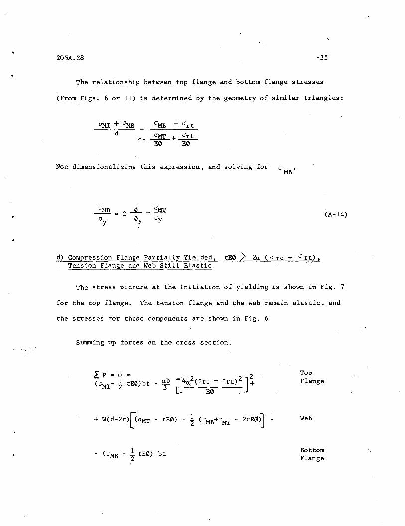
The relationship between top flange and bottom flange stresses
(From Figs. 6 or 11) is determined by the geometry of similar triangles:
aMT artd- ~+ E0
..
Non-dimensionalizing this expression, and solving for a MB'
(A-14)
d) Compression Flange Partially Yielded, tE(Il > 20, ( arc + art).Tension Flange and Web Still Elastic
The stress picture at the initiation of yielding is shown in Fig. 7
for the top flange. The tension flange and the web remain elastic, and
the stresses for these components are shown in Fig. 6.
Summing up forces on the cross section:
- (aMB - ! tE(Il) bt2
TopFlange
Web
BottomFlange
• 20SA,28
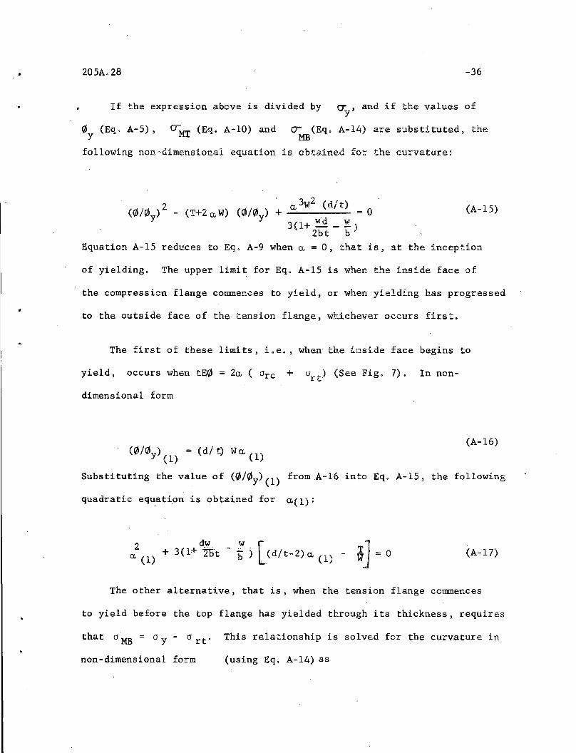
If the expression above is divided by
-36
a: , and if the values ofy
0y
(Eq, A-S) , O'MT (Eq. A-10) and rr (Eq, A-14) are substituted, theMB
following non-dimensional equation is obtained for the curvature:
2 a. 3W2 (d/t)(r/J/C/Jy) - (T+2 a. W) (0/0y) + ~--- = 0
3(1+ ~'d _ !:L)2bt b
(A-1S)
(A-16)
Equation A-1S reduces to Eq, A-9 when a. = 0, that is, at the inception
of yielding, The upper limit for Eq, A-1S is when the inside face of
the compression flange commences to yield, or when yielding has progressed
to the outside face of the tension flange, whichever occurs first.
The first of these limits, i.e., when the inside face begins to
yield, occurs when tE0 = 20. ( arc + art) (See Fig, 7), In non-
dimensional form
(C/Jl0 y ) (1) = (d/ t) Wa. (1)
Substituting the value of (0/C/JY)(1) fromA-16 into Eq, A-1S, the following
quadratic equat~on is obtained for 0.(1):
2 3 ( 1+ d~.t - w. [a. (1) + 4D b ) :.(dlt-2) a. (1) - ~J = 0 (A-17)
The other alternative, that is, when the tension flange commences
to yield before the top flange has yielded through its thickness, requires
that a ME = a Y - a rt· This relationship is solved for the curvature in
non-dimensional form (using Eq. A-14) as
• 20SA.28
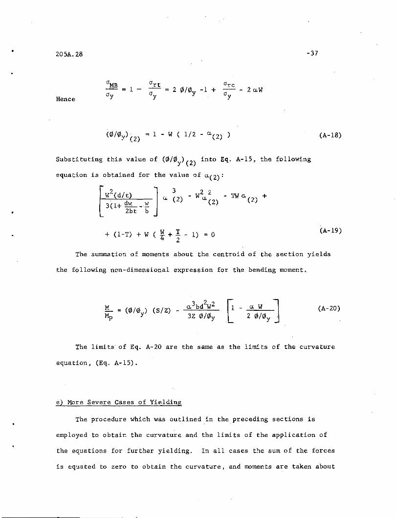
Hence= 2 C/J/0y -1 +
-37
(0/C/J ). = 1 - W ( 112 - C,(2)· )Y (2)
Substituting this value of (C/J/0Y)(2) into Eq. A-1S, the following
equation is obtained for the value of a,(2):
(A-18)
2 2 "- W u. - i'W a. (2) +
(2) ,
+ (l-I) + W ( *+ ~ - 1) = 0(A-19)
The surrmw.tion of moments about the centroid of the section yields
the following non-dimensional expression for the bending momento
MMp
G- a W JL 2 C/J/0 y ,(A-20)
'.
The limits· of Eq. A-20 are the same as the limits of the curvature
equation, (Eq. A-1S).
e) More Severe Cases of Yielding
The procedure which was outlined in the preceding sections is
employed to obtain the curvature and the limits of the application of
the equations for further yielding. In all cases the sum of the forces
is equated to zero to obtain the curvature, and momen.ts are taken about

205A.28 -38
the centroid of the original cross section to obtain the bendingtl1C)ment.
The resulting equations are su~rized below:
1) The limit of elastic behavior (Fig. 6)
l1oment:
Curvature:-(M/~)el. lim. = T/f
(f/J/f/JY)el. lim. = T
2) Compression flange partially yielded (Fig. 7)! tension flangeand web elastic (Fig. 6) .
Curvature:
a 3 W2 (d./t)(f/J/f/Jy ) 2 - (T+2 Ci W) (0/0y ) + = 03(1+ wd ..- ~)
2bt b
~loment:
M = (0/¢y) (l/f) lip
Limi ts: 0 ~ a. ~ 0.(1) .or 0' a., 0.(2) whichever is smaller j
0.(1) and 0.(2) are defined by:
2 [dW. n(l) + 3 7Et-
[
W2(d/t) ~i3(dw _ ~ + 1)
2bt b
3) Compression flanse partially yieldedand web elas tic (Fig .7)
Curvature:
(Fig. 8» tension flange.

[d/t (1 + dw _
2bt
•2Q5A,28
Moment:
(0Ny ) 2 + {3W(d/ t)
+ 3W(d/t)2 {~~2 _ (
-39
~) - ~\(0/0Y) +
(T + 2 o.~i = 0
M .
Mp(1- ~) +0. 2 W(l-t/d)
Limits:
- a. (tl d) (1- 4t)}3d
•0.(1) .<. 0. <; 0.(3) Y= 0
where 0.(3) is defined by:
~W2 L1 + 3 (d/t) (d/t-1)]~ 20.(3) -
{
' 2
+ . l-W + W4 + 3W (dl t) 2 (1+ wd _ ~) (1 - T - ~)1 = 02bt b 2 ~
4) Compression flange partially yielded (Fig, 7), tension flangepaitially yielded (Fig, 9), web elastic (Fig, 6),
Curvature:
W2 (0. 3 - 1ff3 ) (d/t)
3( 1+ wd _ !!)2bt b
= 0
•205A.28
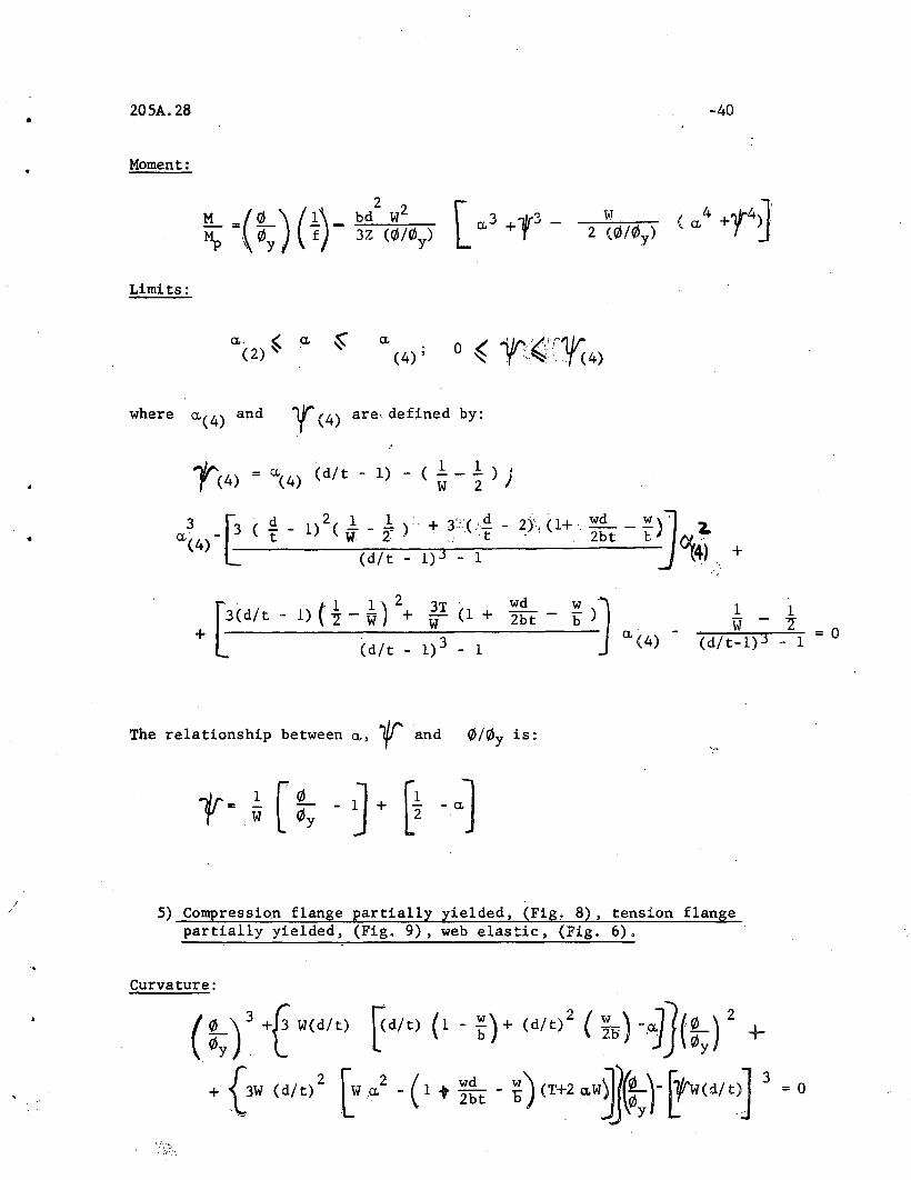
Moment:
Limits:
[ ..3 +r- w
-40
. I. "lt/]( a. '+ + T t.+~J
a. , a. ~(2)'" .
a.(4) ,
•
where 0.(4) and ~(4) are, defined by:
The relationship between a., ~ and 0/0y is:
1 1W - "2"
(d/t-l)3 - 1 = 0
5) Compression flange partially yielded, (Fig, 8), tension flangepartially yielded, (Fig. 9), web elastic, (Fig. 6).
Curvature:
(:y)3 +t W(d/t) [<d/t) (1 - ~)+(d/t) 2 ( ~li) _~](:y) 2 +
+ {3W (d/t) 2 [W ..2
- ( 1 t ~~t - ~) (T+2 "w~)J [!'w(d/t)] 3 0 0
205A.28
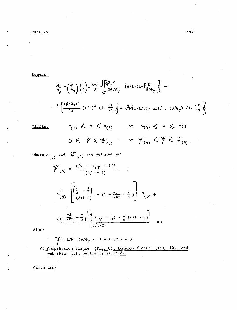
Moment:
-41
~ =('~)':(1:.)_ btd J.I~ (d/tHl-1l ~ +~ \ f/J y f Z lL 3f/J/0y 0/f/Jy J
+ [(f/J/f/Jy)2
2 3t J 2 4t 1' 3W (t/d) (1- 2d ~ + (1, W(l-t/d).- a,{t/d) (f/J/0y) (1- 3d 1
Limits: or
or ,Ir' ?.. llr <. 7/rT (4) -....; T '" T (5)
where (1,(5) and ~ (5) are defined by:
l/W + (1,(5) - 1/2
(d/t - 1)
Also:
~2 R~ -t) wd w J(5) -L~(d/t=2) + (1 + 2bt - b) (1,(5) +
T,yd w fd 1 1 T l(l+7Dt -b)LF (W -"2) - w (d/t - 1~
(d/t-2)= 0
r = l/W (f/J/0y - 1) + (1/2 - (1, )
~) Compr~ssion flange I (Fig. 8) I tension flange I (Fig. 10). andweb (Fig. 11) I partially yielded.
Curvature:

205A.28
where
and
Moment:
Limits:
-42
.Ld/ t -~ +7{f+ ~~t - ~ -(~bt)VJ (r/J/0y ) -
-{W (d/t) [(1+ ~:t - ~) ( ~ +0.) + ( ~ - ~~t) ( ~ ;. ~ ). +
~= l/W (0/0y - 1) + (1/2 - ~)
:p = b~d{(1_t/d) [:y - W(cr. 2.c -2~ -- tId ( :y) El-cr.-'f) (l-~~) +
+ ~W (:y)(t/d)(l-~~~l + (~~21{[t-W(! - cr.) -tId (~)J El- 2~)2 +
+ V(l- 2t/d - 2 -v2J]0,(5) ~ a, ,< 0.5
7) All of the top flange has just yielded.
(Note that this is not a range, but only a point condition. For
bottom flange and web see Fig. 10 and 11.)
Curvature:
-2 (l-T) + ~W + ~~( 1 - ~t)~ -0) ~~V] = 0
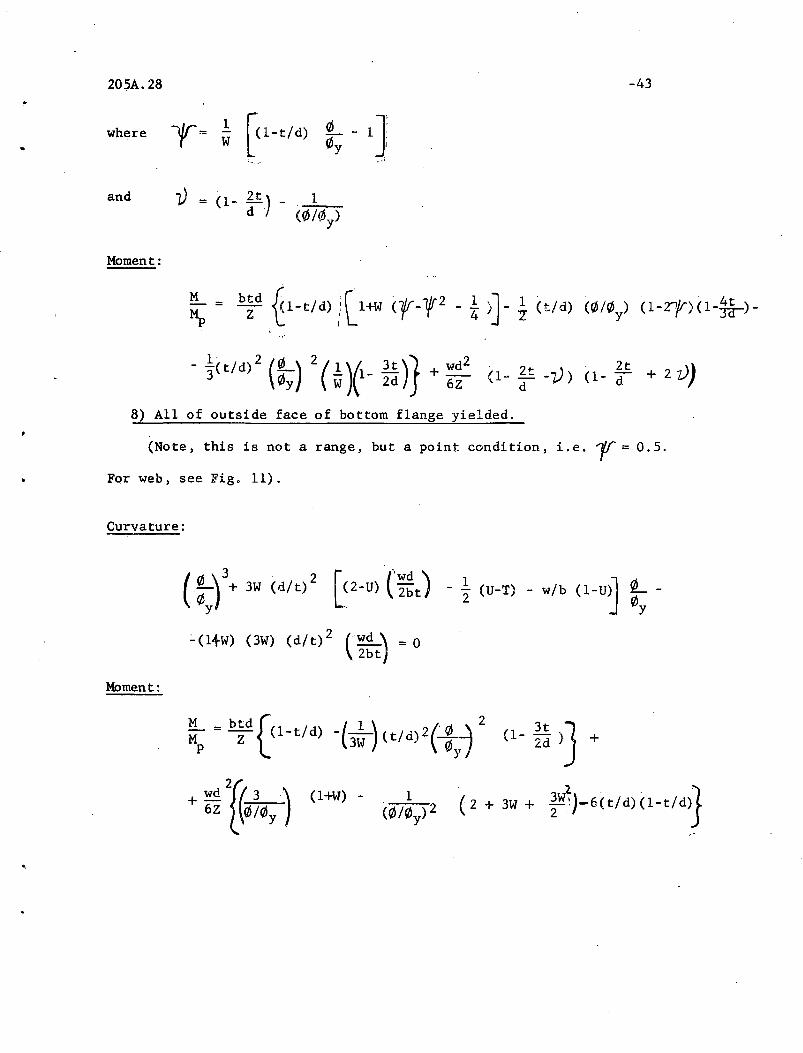
205A.28 -43
and
Moment:
v = (1- ~t)
8) All of outside face of bottom flange yielded.
(Note, this is not a range, but a point condition, i.e. l' = 0.5.
For web, see Fig. 11).
Curvature:
(:Y+ 3W (d/t)2 [(2-0) C;:t) -~ (U-T) - w/b (l-U~ :y :'(l+W) (3W) (d/t)2 (Wd) = 0
2bt
Moment:
(2 + 3W + ~W~J-6(t/d)(1-t/d)}
205A.28 -44
APPENDIX B
.SECTION Dr SECTION DT SECTION Dr
26WF300 578 21WF 73 334 14WF 43 447
230 354 62 246 38 386
194 312 18WF114 867 30 242
150 190 96 646 12WF190 4329
33WF240 496 85 695 106 1785
200 356 64 426 65 786
152 263 60 408 58 842
130 188 50 281 53 709
30WF210 539 16WF 96 899 50 830
172 376 88 769 40 578
132 291 78 833 36 568
108 190 58 497 27 343
27WFl77 555 50 418 10WF112 3600
145 394 36 222 72 1809
114 256 14WF426 7757 49 966
27WF 94 219 246 3712 45 11.30
24WF160 621 142 1580 33 639
130 421 320 5147 29 696
120 423 136 1570 21 329
100 309 111 1124 8WF 67 3221
94 342 87 742 31 925
76 305 84 901 28 1010
21WF142 793 78 766 24 789
112 521 74 895 20 590
96 544 61 640 17 500
82 412 53 630
205A.28 -45
Buckling in thestrain hardeningrange. I
Inelastic buckling
Elastic buckling
AB~
\E\ Be:
\ eo:\\\\c
,
X . : I~Bendin9 about x-x axis 0
• L
Fig. 1 MOMENT-VERSUS-LENGTH CURVE FOR SIMPLY SUPPORTED BEAM
Initial
•
,·'-seam with SmallImperfection
-------------3ilI..._u ,~
•I i.'
•
Iv
Mp . _ ... -._- ....---".-'
"-'-'
/.-........=:--
u
------~----------_4S'- V
a) b)
Fig. 2 ILLUSTRATION OF THE NATURE OF LATERAL BUCKLING

.Y
--47
•
..
d
.d.f
d2'
=.....--., '.-..- w
b
.. X
Fig. 3 THE IDEALIZED WIDE~Wlb~GE CROSS SECTION

20SA.28 -48
•
Elastic Limit
en{30::
• .~
•
EySTRAiN
E$t
Fig. 4 IDEALIZED STRESS-STRAIN DIAGRfu~ IN TENSION AND COMPRESSION
tTrc = 0.:3 tTy
,CTrt =[bt+W~~-2t UCTrc
or .·~rc
Fig. 5 ASSUMED RESIDUAL STRESS PA1~ERN

205A.28
T-r-C
.,49
•
•
t
d-2t
0) COMPRESSIONFLANGE
b) TENSIONFLANGE
c) WEB
Fig. 6 STRESS DISTRIBUTION IN THE ELASTIC RANGE

205A.28 -50
1-'--..,..------.';/TTC
--r---
---ab
2a <arc +CTrt)t------."....~-----&..
EeJ>t
•
Fig. 7 COMPRESSION FLANGE PARTIALLY YIELDED [tE0) 2 ~ (Orc+ (1rt)]

20SA.28 -51
•
Fig. 8 COMPRESSION· FLANGE PARTIALLY YIELDED I-;'E0 <2a,( CJ +CJ )1~ ,.. rc rt~

205A.28 -52
2'"<orc +art )E,
Oft '
21Jt{O;:c+Oftl 1,,'," J" "" ",~ ~ ........,q~--,,...f--..,,
~/ /........c"----+--........
~~ ~------+-..."•
Fig. 9 TENSION FLANGE PARTIALLY YIELDED [tE0) 2t(Circ+ art)]

205A.28
tE4>b .2(O'"rcfort)
,~ ,
. ,I ,I ,I,'
art
-53
TCT
•
Fig. 10 TENSION FLANGE PARTIALLY YIELDED [tE0 <2t<a rc+crrt~
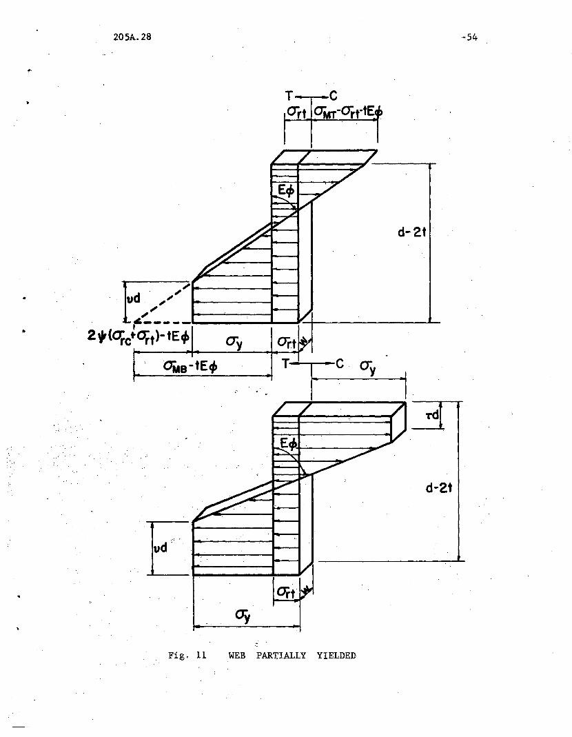
205A.28 -54
T Cart CTMT-orrtEl ~
/ /. //
~4> /i~7
~
~ yd-2t
/~
"d ~~
~
~" vf'-----tOit)-tE, ~. ort~y
0
,OMB-tE4> T c CTy
d-2t
Fig. 11 WEB PARTIALLY YIELDED
, 20SA. 2[; -55
.,
1.0
0.1
~"
-;j; vs ay
0' 0.2
.. \
~---II.Ortf~'~y0.8
0.6
1.0 1.6
~ .
" "1' vs '"y
0~2
·~:'-----L-----~.L.-_-.,.,.,....L-~----_..I...-----'0.8
0.5
ip
O.9
0.8
Fig 0, 12 MOMENT AND CURVATURE VERSUS TENSION AND COMPRESSION FLANGEYIELDING (8WF31)

, ab
",
'.,
205Ao 28
y b"2
-56
t
c'cs
---,..bI--I-- . -_. -- X
t
d
Fig. 13 THE "EFFEC'l'IVE u, CROSS SECTION
•
205A.2.8
0.5 ",=0
..·,57
0.4 t---+---+--+--+----I----t-\!~ab-H I-+-ab
•
"
..
"'b "'b'" =0.1
'" =0.20.1J---+----+-~-+--_+_-~..".--___J~~~~_l_
0.5
BI
1.0
205A.28 -58
0.5
ab-H H-ab
Il-+- 2",o
'I' =0.4
'" =0.3'" =0.2",=0.1,0
O~~-~--------'----...L--....a...---.L..-----------0.05 .. 0.10 0.15 0.20 . 0.25
0.3 J--,--...:l~--I--
0.4
0.2 1------I-----'"'IilI:~~I_-
"
Fig. 15 WARPING STIFFNESS OF THE YIELDED CROSS SECTION
205A.28 -59
,.
"
1.0
0.9M-Mp
0.8
0.7
1.0
0.25
Yield Point-~
~
0.10. 0.05/or 82 0.20
itFig.16 MOMENT - VERSUS - BENDING AND WARPING STIFFNESS
!
0.7
0.9
MM.'P .
0.8 ,;'
..
N0
LV1
1.0 Strain .f- ~>
Hardening· .N00
~ i)Mo \ Mo Mo
-±-Elastic
8YF31Limit Strong Axis
t Bending
0.5il
r:
800O~--~--_I..-_-~--_.L--__-..L..._-_.L--~-------:--
O· ·100 200 300 400 500 60.91.6.)700 :
v· "ry cr
I
'"o
Fig. 17 BUCKLING CURVE FOR 8WF31 SECTION
'" .
1.0
0.7
0.6
o
Solution Includ ingResidual Stress
100 200
Solution Negl~cting
Residual Stress
Limit
~ 30~(h)~-. ry cr
400
No~N00
Fig. 18 INFLUENCE OF RESIDUAL STRESS ON LATERAL BUCKLING (8WF31)
• • ,
___ 27VF94---- -------IIExactll Curves===~- Approximate Curves
0.5
Na
1.0 VI>
Mo MoN(JO
(~ "%)(MO ) r L
~
Mp cr x-I-x
O'--------'----.....L----"-------:--I----~---..L------...---...,I
. a 100 200 300 400 500 600(1.. )700 800
ry crFigo 19 LATERAL BUCKLING CURVES FOR WIDE=FLANGE SECTIONS

r
.G -
,o
f
•

..
•
1.0205A.28
--=.- -- -. --.M 0.9
Mp0.8
Approximation for0.7 all w= Sections
M 0.9
MP0.8
0.7Approximation for.all 'IF Sections
0.10 , ,0.15. 82
0.20
-63
27VF94
14YF246
1.0
025
Fig. 20 AVERAGE STIFFNESS REDUCTION CURVES
.. ','
IC1'oj::'·
NoVI>- ..I"00
. {.'
1500
tI. . o.
27W:-94~8._W:_3~_
14VFI42------14 VF246---------=----- .
500
LdAISC tit Rule (Eq.16)
Fig. 21 COMPARISON OF THEORY WITH Ld/bt RULE
Transition Curve
Ld_______-~::~~_-_-_-_\f\M~~.~rc_-_!~ bt _
o
0.9
0.5
.. .
o
. 0.6

.,
"" •
I. (j\
\.n
N_ (Xl
"
ZTYF94_8.W=~1_
14 VF 142---.-__14 'IF 246_
Design Recommendation
..Eq~.21
Fig. 22 PROPOSED POSSIBLE DESIGN MODIFICATION
1.0,....·~~
0.7
0.5
0.6
0.4
~\O... ___
~)>-o .~-..l._---l....._..L...-~_--..L..._....l.-_.L...----1._....I--_..1-----L_--L-_...L.-_L....----'--~----'
0500 1000 LcJ; 1500

1.0
0.9
(MO)Mc~aU
0.8
0.7
0.6
0.5
:" .. •
NoVt;l>
N00
I0\0\
205A.28
LOII .. •Exact Solution
"eRe" Method
i . (MO )Mp
0.5
100
(iy)200 300
F . ~4 -'OMPA D II II ANnl.g. 1,. (l.,;Al>.ISON BEl'lAl'EEN EXACT SOVJ'JrlON jlJl I 'eR.iC II ME;tHOD
•\,.
205A.28
REF ERE N C E S
-68
1. Bleich, F.BUCKLING STRENGTH OF METAL STRUCTURES, McGraw-Hill Book Co.,New York, 1952.
2. Lee, G. C.LITERATURE SURVEY ON LATERAL INSTABILITY AND LATERAL BRACING'REQUIREMENTS, Welding Research Council Bulletin 62, July 1960.
3. White,M. W.THE LATERAL-TORSIONAL BUCKLING OF YIELDED STRUCTURAL STEEL MEMBERS,Ph.D. Dissertation, Lehigh University, 1956.
4. Wittrick, W. H.LATERAL INSTABILITY OF RECTANGULAR BEAMS OF STRAIN HARDENING~~T~RIAL UNDER UNIFORM BENDING, Journal of Aeronautical Science,19 (12), p. 835 (Dec. 1952).
5" Neal, B.G.THE LATERAL INSTABILITY OF YIELDED MILD STEEL BEAMS OF RECTANGULARCROSS SECTION, Philosophical Transactions of the Royal Society ofLondon 242 (A) (Jan. 1950).
6. Horne, M. R.CRITICAL LOADING CONDITIONS OF ENGINEERING STRUCTURES,Ph.D. Dissertation, Cambridge University, 1950. '
7. Galambos, T. V.INELASTIC LATERAL-TORSIONAL BUCKLING OF WIDE FLANGE COLUMNS,Ph.D. Dissertation, Lehigh University, 1959.
8. Haaijer, G.PLATE BUCKLING IN THE STRAIN HARDENING RANGE, Transactions of theASCE, 124, (2968) p.117 (1959).
9. Ketter, R. L.; Kaminski, E. L.; Beedle, L. S.PLASTIC DEFORMATIONS OF WIDE-FLANGE BEAM-COLUMNS, Transactionsof the ASCE, 120,(2772) p. 1028,(1955).
10. Timoshenko, S.THEORY OF ELASTIC STABILITY, McGraw-Hill Book Co., New York, 1936.
11. Timoshenko, S.STRENGTH OF MATERIALS, Vol. II, D. Van Nostrand Book Co.,New York, 1948.
12. de Vries, K.STRENGTH OF BEAMS AS DETERMINED BY LATERAL BUCKLING, Transactionsof the ASeE, 112, p. 1245 (1947).

• 205A.28
- .'
-69
\13. DIN 4114
GERMAN BUCKLING SPECIFICATIONS, 1953 (English Translation for CRCby T. V. Galambos and J. Jones, 1957).
14. AISCSTEEL CONSTRUCTION HANDBOOK, American Institute of Steel Construction.
15. CRCGUIDE TO DESIGN CRITERIA FOR METAL COMPRESSION MEMBERS, ColumnResearch Council, 1960.
16. Clark, J. W.; Hill, H. N.LATERAL BUCKLING OF BEAMS, Proceedings of the ASeE, ProceedingsPaper 2559 (ST7) p. 175, (July, 1960).
17. Galambos, T. V.; i Ketter, R. L.COLUMNS UNDER COMBINED BENDING AND THRUST, Proceedings of the ASCE,
• Proc. Paper 1990 (EM2) p. 1, (April, 1959).
18. AISC• PLASTIC DESIGN IN STEEL, American Institute of Steel Construction,
1959.
19. Lee, G. C.INELASTIC LATERAL BUCKLING OF BEAMS AND LATERAL BRACING REQUIREMENTS,Ph.D. Dissertation, Lehigh University, 1960.