INELASTIC DYNAMIC ANALYSIS OF TWO INDUSTRIAL STRUCTURES …2)0083.pdf · INELASTIC DYNAMIC ANALYSIS...
10
83 INELASTIC DYNAMIC ANALYSIS OF TWO INDUSTRIAL STRUCTURES D. L. Dutchison* and D. D. Spurr* ABSTRACT The earthquake effects on two structures supporting steam generation plant at the New Zealand Forest Service Waipa State Mill weife examined using an inelastic dynamic analysis computer program. The geometry and structure of the plant and support systems indicated that the equivalent static method would not be appropriate for analysis. One of the support structures incorporated axial energy dissipating devices and performance of these was confirmed by testing of a full-scale prototype. The second structure was characterised by an unsymmetrical distribution of stiffness. An equivalent two-dimensional representation of the structure plan was analysed to assess the effect of torsion on the inelastic response to seismic loading. INTRODUCTION New Zealand Forest Service (NZFS) are currently replacing the generation plant at Waipa Sawmill, near Rotorua, to make the mill self-sufficient in steam and electricity produced from waste wood. Items of new plant are generally supported on braced or portal steel structures. Figure 1 shows in shaded outline the structures considered in this paper. At left is the braced frame supporting the woodbin. In the north-south direction, this frame is coupled to the top of the boiler which is supported on a braced frame. The tubular air heater support structure has identical portal frames at east and west faces, but braced frames at the north and south faces, each of very different characteristics. Both plant and support structures were designed in Babcock International (NZ) Ltd, Sydney Office, with Ministry of Works and Development (MWD) Head Office, commissioned by NZFS to carry out special analyses to determine design seismic load effects on the support structures. SELECTION OF EARTHQUAKE RECORDS FOR ANALYSIS The site of the mill is located in Zone B [1], but very near the boundary with Zone A. Significant seismic attack is believed to more likely result from smaller nearby earthquakes rather than from larger distant events. In consultation with the Engineering Seismol- ogy Section of the DSIR Physics and Engineering Laboratory, three earthquake records were selected for analysis, namely Artificial B2, El Centro (1940) NS and Olympia N80E. All three records were scaled down to 5/6 times their acceler- ation values to account for the lower seismicity of Zone B and the Olympia record was scaled up by a factor of 1.3 * Ministry of Works and Development, Wellington. for equivalence. This was done on the assumption that El Centro NS corresponds to the level of earthquake envisaged in NZS 4 203 [1] for Zone A and the other two earthquake records are equivalent. Comparison of the three response spectra shown in Figure 2 shows reasonable similarity for structures with natural periods less than about 1.2 seconds. BOILER SUPPORT STRUCTURE The boiler is a rigid upright box rising to approximately 20 metres above ground. The support structure is 4.8 m x 3.5 m in plan. On three faces it is not more than 3.5m high, but the west face is 5 m high as shown in Figure 3. Designing the support structures to remain elastic would have resulted in unacceptably large stresses being induced in the boiler under seismic loading. However, the potential for energy dissipation as a result of plastic deformation was confined to only the few diagonal members of the support structure. Specifically designed energy dissipating devices were therefore incorporated into the diagonal members of support frames in order to achieve desirable load reduction as well as to improve the reliability of the base structure. The woodbin structure exhibited only modest yielding in braces at the base and therefore dissipating devices were not used there. Figure 4 shows the computer model used to analyse the north and south faces of the boiler support structure. The DRAIN 2D [4] computer program was used to carry out inelastic analysis. A value of 2% of critical damping for the first two modes of vibration was generally used, although sensitivity analyses were also performed at higher and lower values of damping. The weight distribution on the boiler support structure is unsymmetric, with approximately two thirds of the weight BULLETIN OF THE NEW ZEALAND NATIONAL SOCIETY FOR EARTHQUAKE ENGINEERING. Vol. 19. No. 2. June 1966
Transcript of INELASTIC DYNAMIC ANALYSIS OF TWO INDUSTRIAL STRUCTURES …2)0083.pdf · INELASTIC DYNAMIC ANALYSIS...

83
INELASTIC DYNAMIC ANALYSIS OF TWO INDUSTRIAL STRUCTURES
D. L. Dutchison* and D. D. Spurr*
ABSTRACT
The earthquake effects on two structures supporting steam generation plant at the New Zealand Forest Service Waipa State Mill weife examined using an inelastic dynamic analysis computer program. The geometry and structure of the plant and support systems indicated that the equivalent static method would not be appropriate for analysis. One of the support structures incorporated axial energy dissipating devices and performance of these was confirmed by testing of a full-scale prototype. The second structure was characterised by an unsymmetrical distribution of stiffness. An equivalent two-dimensional representation of the structure plan was analysed to assess the effect of torsion on the inelastic response to seismic loading.
INTRODUCTION
New Zealand Forest Service (NZFS) are currently replacing the generation plant at Waipa Sawmill, near Rotorua, to make the mill self-sufficient in steam and electricity produced from waste wood. Items of new plant are generally supported on braced or portal steel structures.
Figure 1 shows in shaded outline the structures considered in this paper. At left is the braced frame supporting the woodbin. In the north-south direction, this frame is coupled to the top of the boiler which is supported on a braced frame. The tubular air heater support structure has identical portal frames at east and west faces, but braced frames at the north and south faces, each of very different characteristics.
Both plant and support structures were designed in Babcock International (NZ) Ltd, Sydney Office, with Ministry of Works and Development (MWD) Head Office, commissioned by NZFS to carry out special analyses to determine design seismic load effects on the support structures.
SELECTION OF EARTHQUAKE RECORDS FOR ANALYSIS
The site of the mill is located in Zone B [1], but very near the boundary with Zone A. Significant seismic attack is believed to more likely result from smaller nearby earthquakes rather than from larger distant events. In consultation with the Engineering Seismology Section of the DSIR Physics and Engineering Laboratory, three earthquake records were selected for analysis, namely Artificial B2, El Centro (1940) NS and Olympia N80E. All three records were scaled down to 5/6 times their acceleration values to account for the lower seismicity of Zone B and the Olympia record was scaled up by a factor of 1.3 * Ministry of Works and Development,
Wellington.
for equivalence. This was done on the assumption that El Centro NS corresponds to the level of earthquake envisaged in NZS 4 203 [1] for Zone A and the other two earthquake records are equivalent. Comparison of the three response spectra shown in Figure 2 shows reasonable similarity for structures with natural periods less than about 1.2 seconds.
BOILER SUPPORT STRUCTURE
The boiler is a rigid upright box rising to approximately 20 metres above ground. The support structure is 4.8 m x 3.5 m in plan. On three faces it is not more than 3.5m high, but the west face is 5 m high as shown in Figure 3. Designing the support structures to remain elastic would have resulted in unacceptably large stresses being induced in the boiler under seismic loading. However, the potential for energy dissipation as a result of plastic deformation was confined to only the few diagonal members of the support structure. Specifically designed energy dissipating devices were therefore incorporated into the diagonal members of support frames in order to achieve desirable load reduction as well as to improve the reliability of the base structure. The woodbin structure exhibited only modest yielding in braces at the base and therefore dissipating devices were not used there.
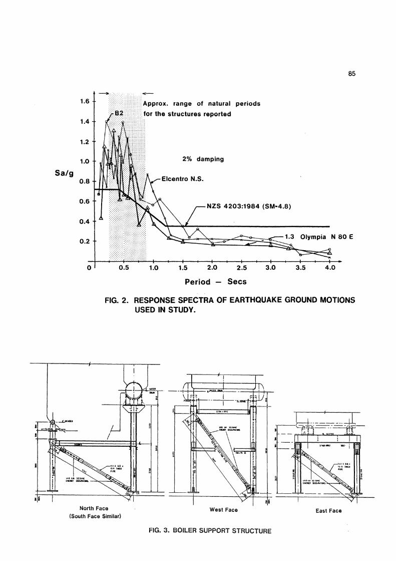
Figure 4 shows the computer model used to analyse the north and south faces of the boiler support structure. The DRAIN 2D [4] computer program was used to carry out inelastic analysis. A value of 2% of critical damping for the first two modes of vibration was generally used, although sensitivity analyses were also performed at higher and lower values of damping.
The weight distribution on the boiler support structure is unsymmetric, with approximately two thirds of the weight
BULLETIN OF THE NEW ZEALAND NATIONAL SOCIETY FOR EARTHQUAKE ENGINEERING. Vol. 19. No. 2. June 1966

LINK T R A N S M I T S A X I A L LOAD ONLY
SOOT BLOWER
FIG. 1. PART ELEVATION OF STEAM PLANT COMPLEX:
EAST FACE
85
Approx* range of natural periods
B2 for the structures reported
Sa/g
2% damping
1.3 Olympia N 80 E
FIG. 2. RESPONSE SPECTRA OF EARTHQUAKE GROUND MOTIONS USED IN STUDY.
North Face (South Face Similar)
West Face East Face
FIG. 3. BOILER SUPPORT STRUCTURE

86
being carried by the columns on the west side. This effect was accounted for within the limitations of two-dimensional analysis by apportioning the total mass to each side frame in proportion to the fraction of total weight supported. The magnitude of base accelerations was increased by 10% to allow for accidental eccentricities and accommodate the seismic torsion requirements of NZS 4 2 03.
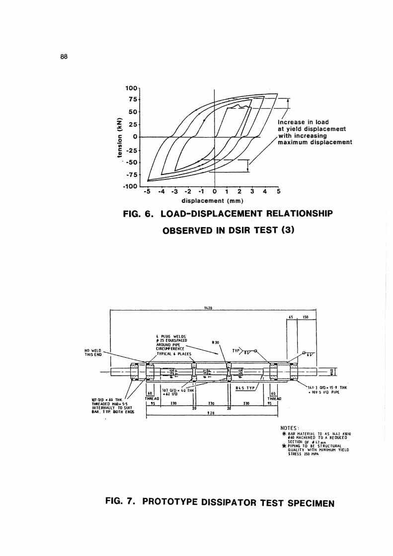
The bilinear model of the dissipators is shown in Figure 5. This was deduced from the earlier testing of axial load dissipators by MWD [5] and DSIR [3]. The model is unable to. simulate increases in stress at a given strain which result from increasing maximum plastic strain imposed in preceding cycles (Figure 6). The effects of strain hardening are therefore generally underestimated. To compensate for this and to allow a margin against yielding elsewhere in the boiler and support structure, all peak load effects obtained from the inelastic analysis were increased by 25% for design purposes. A further limitation of the model was the assumption of an equal rate of strain hardening for both tension and compression loading. However, while the prototype test shows significant strain hardening when loaded in tension, very little is evident on the compression part of the loading cycle (Figure 8 ) .
Table 1 compares maximum values of base shear and diagonal brace loads for elastic and inelastic analysis of the support structures. In the case of inelastic response, the base shear tabulated includes the 25% overstrength factor. The base shear coefficient, on the other hand, is as calculated in NZS 4203, i.e. without the overstrength factor applied. Generally, analysis during the B2 record determined design values. The cumulative plastic deformation imposed on the dissipators was always greater than for the other two records, although El Centro and Olympia imposed larger peak displacements and loads in a few cases. A maximum displacement of 64 mm at the top of the boiler resulted from shaking in the east-west direction and 39 mm in the north-south direction.
The criterion used for selecting the dissipator strength was the greatest difference between maximum displacement under tensile loading and that under compressive loading predicted for any of the earthquake records used. The design limited adopted was 12 mm, based on two dissipators of the type tested by MWD for the Wanganui Departmental Building [2]. Optimisation of dissipator strengths was however hindered by several geometry changes made to the boiler support structure at too late a stage to enable further analyses to be made. These changes were made to accommodate revised layouts of ducting and piping.
It is of interest to compare the base shear coefficients obtained from the inelastic dynamic analyses with the value obtained from NZS 4203: For short period steel buildings in Zone B with diagonal
bracing capable of plastic deformation in both tension and compression, a value of
= 0.20 is obtained. This description arguably fits the east and west support frames of the boiler. However, final values obtained in the special study reported here are well in excess of this figure. While optimisation of dissipator yield values would likely lead to a reduction in the higher values on the east face (Table 1 ) , it is unlikely that values as low as code values would be attained. This reflects the fact that the mass is distributed over a height much greater than that of the base support structure, which is the sole level at which seismic energy is dissipated. The code value of may well be appropriate for the situation where yielding frames are distributed over the total weight of the structure. However, such was not the case in this study.
A prototype 600 kN dissipator was fabricated by NZ Railways Workshop, Moera, and tested by MWD Central Laboratories [5]. Figure 7 shows the prototype and Figure 8 shows part of the behaviour recorded at test. Although the dissipator sustained displacements twice the magnitude of the 12 mm design limit, the lack of excess capacity and the approximate nature of the analyses led to the decision of the client to retain two dissipators per brace.
The cost of the single prototype dissipator was $1,350 at October 1984. This unit cost would be expected to reduce when several were being made in the contract.
The development and testing of the prototype dissipator is reported in Reference 6. The production version of the dissipators included a third intermediate lateral restraint, reducing the maximum unsupported length of yielding bar from 4.9' diameters to 3.6 diameters. This change was made to improve post-elastic performance under compression loading.
TUBULAR AIRHEATER
The tubular airheater is a rectangular box structure of plan dimensions approximately 1.8 m x 3 m. The height of the box above the structure which supports it is about 4.2m. The airheater shell is fabricated from pipes welded to produce a continuous steel sheathing, and is relatively stiff.
The base support structure was originally reasonably symmetrical in each horizontal direction. However, at a late stage, changes were made to accommodate ancillary equipment. The unsummetrical layout shown in Figure 9 resulted. The X-braced frame is about 15 times as stiff as the remaining three frames. Thus, torsional response was of some concern for earthquake response as a result of shaking in the east-west direction. Figure 9 shows the model used to consider this direction of loading. The lateral inplane stiffness of each of the support frames was represented by the axial stiffness of an equivalent truss member. The axes of truss members representing east and west
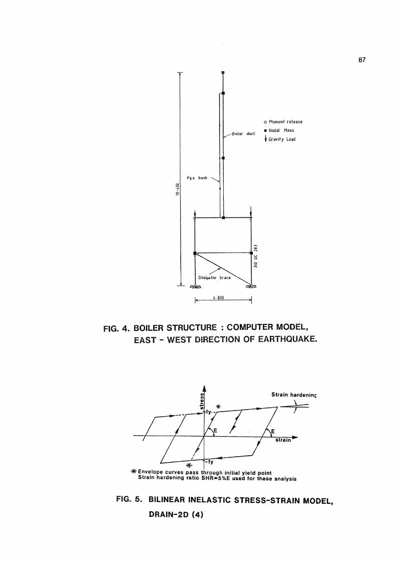
FIG. 4. BOILER STRUCTURE : COMPUTER MODEL, EAST - WEST DIRECTION OF EARTHQUAKE.
FIG. 5. BILINEAR INELASTIC STRESS-STRAIN MODEL,
DRAIN-2D (4)
100
-100 *—i 1 . . — 4 - . . . • . -5 -4 -3 -2 -1 0 1 2 3 4 5
displacement (mm)
FIG. 6. LOAD-DISPLACEMENT RELATIONSHIP
OBSERVED IN DSIR TEST (3)
H 1 - 3 0 / D « 15 ! T H K
- 109 5 HQ PlPi
W 7 CVD * 6 0 THK T H R E A D E D H 6 0 - 5 5 I N T E R N A L L Y TO S U I T B A R . T Y P B O T H ENDS
N O T E S : * BAR H A T E R I A L TO AS I U J KWKJ
* 6 0 M A C H I N E D T O A R E D U C E D S E C T I O N OF 4 LI mm P I P I N G T O BE S T R U C T U R A L Q U A L I T Y W I T H M 1 N I M U H Y I E L D STRESS 2S0 H P A
FIG. 7. PROTOTYPE DISSIPATOR TEST SPECIMEN

FIG. 8. PROTOTYPE DISSIPATOR: PART OF TEST LOAD HISTORY
and South Faces E a s t a n d W e g , F a c e „
FIG. 9. TUBULAR AIR HEATER: BASE SUPPORT STRUCTURES.

90
faces were aligned parallel to the direction of earthquake loading and the north and south face equivalent members at right angles to it. The tubular airheater tower was modelled as a vertical cantilever with base node fixed as regards rotation and vertical movement. The in-plane stiffness of the airheater base is represented as high flexural stiffness assigned to the shaded L-shaped element shown in Figure 10.
The model shown in Figure 10 is capable of predicting only lateral shear values directly. Overturning effects associated with this shear can be separately calculated however y and amount to about 35% of the weight of the structure per column.
As with the boiler and woodbin support structures, the earthquake records were increased by 10% to account for accidental eccentricity, etc. Time-history plots were made to obtain a measure of period for the purposes of calculating a damping coefficient. Indicative values of ductility demand were obtained from maximum member deformations.
3. Tyler, R.G. and Heine, A.J., "Tests on an Axially Loaded Steel Energy Absorber", Bulletin of the New Zealand National Society for Earthquake Engineering, Vol. 17, No. 1, March 1984 .
4. Powell, G.H., "Drain - 2D Users Guide", EERC 73-22, University of California, Berkeley, 1973.
5. Jacks, D.H., "Testing of Waipa Sawmill Energy Dissipators", Structures Section Report, MWD Central Laboratories, December 1984 .
6. Spurr, D.D., "Application of Axially Loaded Steel Energy Dissipators in a Boiler Support Structure", Research and Development Report 8 6/1, Office of the Chief Structural Engineer, Ministry of Works and Development, March 1986.
Table 2 summarises maximum ductility values and deflections obtained for the parallel braced frames. Ductility demand is seen to be modest. The portal frames (which are at right angles to the direction of earthquake considered in these analyses) did not yield.
The maximum displacement of 49 mm is also modest, being about 1% of the height of base support structure. This displacement is read directly from the model output since actual values of loading (the earthquake record), member stiffness and yield load are included in the model.
DISCUSSION
Inelastic dynamic analysis techniques are advisable for evaluation of the seismic response of structures were ductility demand is concentrated in only a few locations, especially when there is also a non-uniform mass or stiffness distribution. The equivalent static approach, applicable to ordinary buildings, is not appropriate. Adequate two-dimensional models can be devised to simulate three-dimensional situations for some relatively simple structures.
ACKNOWLEDGEMENT
The permission of the Director of Engineering NZ Forest Service and the Commissioner of Works to report this study is gratefully acknowledged.
REFERENCES
1. NZS 4203:1984, "Code of Practice for General Structural Design and Design Loadings for Buildings", Standards Association of New Zealand, December 1984.
2. Thurston, S.J., "Cyclic Loading of Vallourec Bar Test Specimen", Unpublished MWD Central Laboratories Report, 1979.

2.000
A
Equivalent m a m b a r for
b raced f rame
(2)
Equivalent m e m b e r for
cant i lever b r a c e d I rame
F N
of earthquake motion
(ii)
(0
(iv)
Stiff Member
0-—-o, ( 5 )
A ° in CO
o o q CNJ
Rollers
Equivalent stiff diaphragm at
top of support structure
(iii)
(3)
o o CM
i i
nTrr rmnr
T
•o, o o
V
2.300
FIG. 10. MODELLED TUBULAR AIRHEATER.
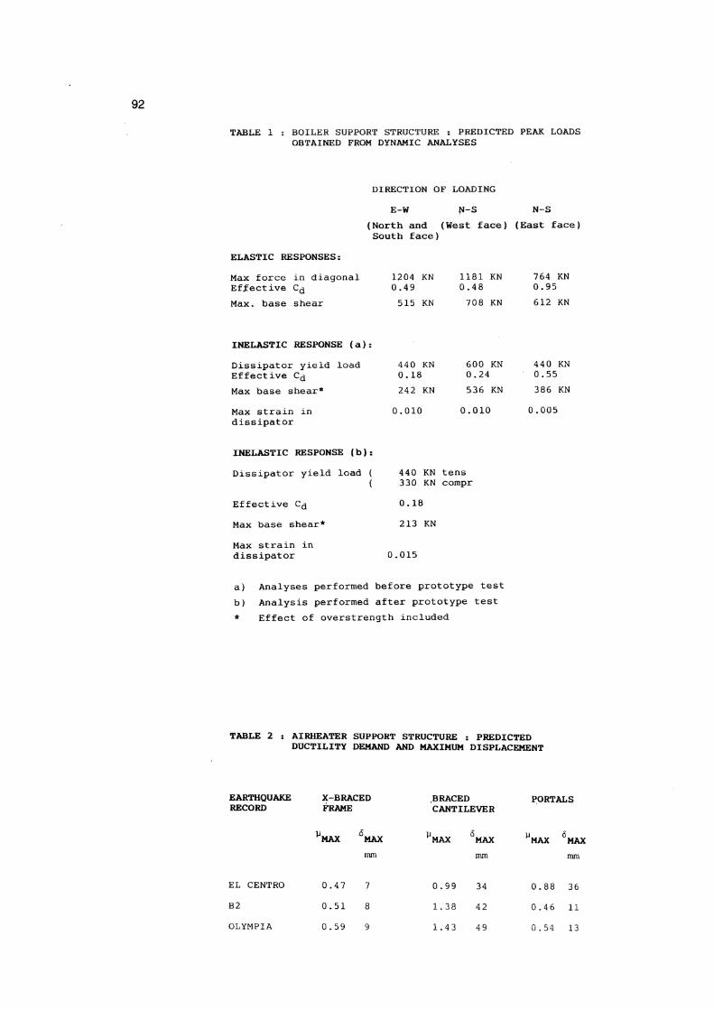
TABLE i s BOILER SUPPORT STRUCTURE : PREDICTED PEAK LOADS OBTAINED FROM DYNAMIC ANALYSES
DIRECTION OF LOADING
E-W N-S (North and (West face) (East face) South face)
ELASTIC RESPONSES:
Max force in diagonal Effective C d
Max. base shear
1204 KN 0.49 515 KN
1181 KN 0.48 708 KN
764 KN 0.95 612 KN
INELASTIC RESPONSE (a);
Dissipator yield load 440 KN 600 KN 440 KN Effective Cd 0.18 0.24 0.55 Max base shear* 242 KN 536 KN 386 KN
Max strain in 0.010 0.010 0.005 dissipator
INELASTIC RESPONSE (b):
Dissipator yield load (
Effective C<j
Max base shear*
Max strain in dissipator
( 440 KN tens 330 KN compr 0.18
213 KN
0.015
a) Analyses performed before prototype test b) Analysis performed after prototype test * Effect of overstrength included
TABLE 2 : AIRHEATER SUPPORT STRUCTURE : PREDICTED DUCTILITY DEMAND AND MAXIMUM DISPLACEMENT
EARTHQUAKE X-BRACED BRACED PORTALS RECORD FRAME CANTILEVER
PMAX 5 MAX ^MAX 6 MAX UMAX 6 MAX mm mm mm
EL CENTRO 0.47 7 0.99 34 0.88 36
B2 0.51 8 1.38 42 0.46 11
OLYMPIA 0.59 9 1.43 49 0.54 13