Industry Webinar - NERC Webinars DL/2017 03 R… · · 2017-04-13• NERC Project 2008- 01...
53
Industry Webinar Reactive Power Planning NERC System Analysis and Modeling Subcommittee (SAMS) March 2017
Transcript of Industry Webinar - NERC Webinars DL/2017 03 R… · · 2017-04-13• NERC Project 2008- 01...

Industry WebinarReactive Power Planning
NERC System Analysis and Modeling Subcommittee (SAMS)March 2017

RELIABILITY | ACCOUNTABILITY2
Webinar Topics
• Reliability Guideline on Reactive Power Planning• Webinar Topics
Fundamentals of reactive power planning Relevant FERC Orders and NERC Reliability Standards Reactive Power Analysis Timeframes Reactive Power Assessment Techniques Reactive Power Coordination Industry Practices
• Goals: Share takeaways from Reliability Guideline on Reactive Power Planning Provide examples of reactive power planning practices Update industry on efforts underway in the NERC SAMS

RELIABILITY | ACCOUNTABILITY3
NERC SAMS
• SAMS webpage• Purpose: support development and advancement of system
analysis and modeling tools, techniques, and capabilities in planning for the reliability and operational security of the BPS
• Key Focus Areas Develop technical reference materials Identify emerging issues and evaluate new analysis techniques Promote coordination between NERC Regions Share lessons learned within industry Support improvement of interconnection-wide models Coordinate with industry experts and industry groups
• Chair: Michael Lombardi, NPCC

RELIABILITY | ACCOUNTABILITY4
Speakers
• Ryan Quint – NERC• Bill Harm – PJM• Rich Kowalski – ISO-NE• John Simonelli – ISO-NE• Gary Brownfield – Ameren• Jose Conto – ERCOT • Durgesh Manjure – MISO

RELIABILITY | ACCOUNTABILITY5
Background,Relevant FERC Orders,
and NERC Reliability Standards

RELIABILITY | ACCOUNTABILITY6
Background
• NERC Project 2008-01 Voltage and Reactive Control Initiated to address FERC Order 693 (¶ 1860-1880)
• Documents produced: Reactive Support and Control White Paper – NERC TIS (approved 6/09) SAR to modify VAR-001 and VAR-002 standards
• Additional recommendations to address planning horizon issues forwarded to the TPL SDT

RELIABILITY | ACCOUNTABILITY7
VAR-001-4.1
• Ensures that voltage levels, reactive flows, and reactive resources are monitored, controlled, and maintained within limits in real-time to protect equipment and reliable operation
• TOPs: Specify system-wide voltage schedule Schedule sufficient reactive resources to regulate voltage for normal
and contingency conditions Operate and direct operation of devices to regulate voltage and reactive
power flows Develop criteria for exemptions to automatic voltage control mode Specify voltage or reactive schedule for generation

RELIABILITY | ACCOUNTABILITY8
VAR-002-4
• Ensures generators provide reactive support and voltage control in order to protect equipment and maintain reliable operation
• GOPs: Operate generators connected to transmission system in automatic
voltage control mode, or other mode as instructed by TOP Maintain TOP’s voltage or reactive schedule, unless GOP is exempted Notify TOP of any changes in status of voltage control Notify TOP of changes in reactive capability
RELIABILITY | ACCOUNTABILITY9
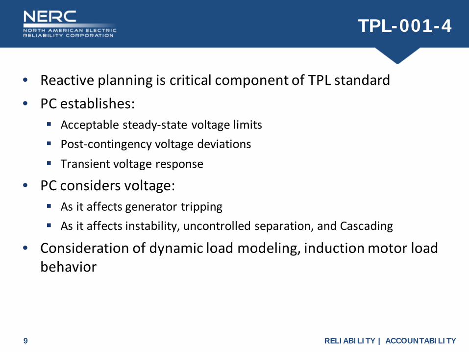
TPL-001-4
• Reactive planning is critical component of TPL standard• PC establishes:
Acceptable steady-state voltage limits Post-contingency voltage deviations Transient voltage response
• PC considers voltage: As it affects generator tripping As it affects instability, uncontrolled separation, and Cascading
• Consideration of dynamic load modeling, induction motor load behavior

RELIABILITY | ACCOUNTABILITY10
FERC Order 827
• Order 827 eliminated exemptions for wind generators from the requirement to provide reactive power
• All newly interconnecting non-synchronous resources will be required to provide reactive power as a condition of interconnection
• Key distinctions: Power factor range Point of measurement Dynamic reactive capability Active power threshold

RELIABILITY | ACCOUNTABILITY11
Reactive Power Fundamentals
What is reactive power?Why is reactive power important?

RELIABILITY | ACCOUNTABILITY12
Dynamic vs. Static Resources
• Dynamic reactive resources Adjust reactive power output automatically in real-time over a
continuous range within a specified voltage bandwidth in response to grid voltage changes
Maintain set point voltage or operate in voltage droop mode Many are power electronics based Can respond within electrical cycles using fast-acting controls
• Static reactive resources Fixed reactive power output at nominal voltage Output varies according to voltage squared Generally switched in and out of service based on system conditions Switching action can be manual or automatic

RELIABILITY | ACCOUNTABILITY13
Reactive Power Resources:Fixed and Switched Shunts

RELIABILITY | ACCOUNTABILITY14
Reactive Power Resources:Transmission Circuits

RELIABILITY | ACCOUNTABILITY15
Reactive Power Resources:Synchronous Generators

RELIABILITY | ACCOUNTABILITY16
Reactive Power Resources:Synchronous Condensers
RELIABILITY | ACCOUNTABILITY17
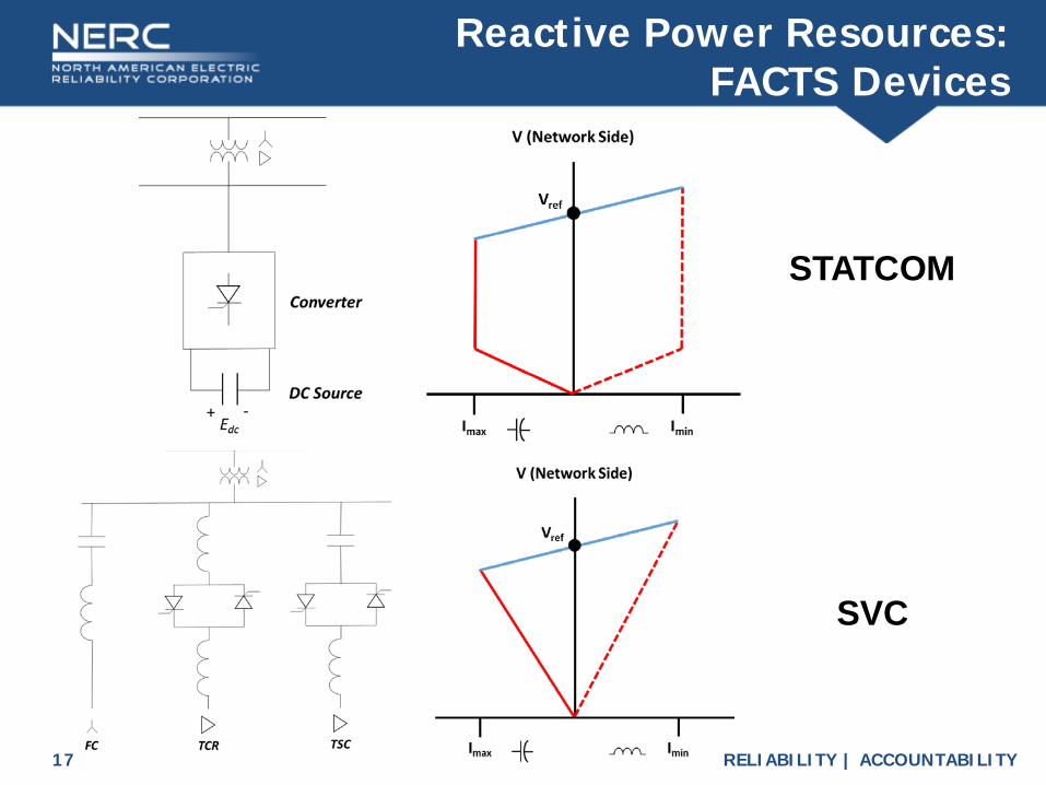
Reactive Power Resources:FACTS Devices
STATCOM
SVC

RELIABILITY | ACCOUNTABILITY18
Reactive Power Resources:VSC HVDC

RELIABILITY | ACCOUNTABILITY19
Reactive PowerAnalysis Timeframes

RELIABILITY | ACCOUNTABILITY20
Steady-State Pre-Contingency
• Voltages maintained within ranges on BPS• Elements maintaining terminal voltage set point value• Manual readjustment of elements throughout day
Shunt capacitor switching, load tap changing, etc.
• Automatic devices continuously operating to maintain steady voltage profile
• Voltage should remain within limits for credible contingencies

RELIABILITY | ACCOUNTABILITY21
Transient

RELIABILITY | ACCOUNTABILITY22
Mid-Term Dynamics
• Dampening oscillations, transitory state• Returning to a new steady-state condition• Dynamic resources adjusting• Generator controls responding• May consider load tap changing based on control delays• Excitation limiters considered• Slower manual controls not considered

RELIABILITY | ACCOUNTABILITY23
Long-Term Dynamics: Post-Contingency
• New equilibrium following contingency• Assess voltage stability and security at this new point• All automatic controls responded
Voltage controls, power factor, governor response, FACTS, AGC, etc.
• Automatic tap changes and switched shunts acting• Manual controls not considered in this timeframe
Manual load tap changing, manual capacitor switching, load shedding
• Assumes operators not acting this quickly

RELIABILITY | ACCOUNTABILITY24
Steady-State: Post-Contingency
• All controls considered• Applicable for associated emergency ratings• Return to within acceptable operating limits• All manual readjustments and automatic controls considered
Generation re-dispatch Transformer tap changing Manual and automatic capacitor switching Fast- or slow-acting RAS Other system readjustments Transmission element switching (e.g., cables)

RELIABILITY | ACCOUNTABILITY25
Reactive PowerAssessment Techniques

RELIABILITY | ACCOUNTABILITY26
Contingency Analysis
• Voltage criteria testing Voltage/reactive contingencies could be different than typical thermal
analysis contingencies Voltage drop criteria: difference between pre- and post- contingency
steady-state voltages (e.g., 2-6% threshold) Absolute voltage criteria: acceptable lower and upper bus voltage
magnitude limits (e.g., 0.95 pu and 1.05 pu)
• Voltage instability will not have converged power flow solution in post-contingency state Tool will generate erroneous conditions (flows, voltages, etc.) Post-contingency case should not be used to assess these conditions Use engineering judgment to study conditions leading up to collapse

RELIABILITY | ACCOUNTABILITY27
QV Analysis
Source: ©CIGRE, 1986
Margin

RELIABILITY | ACCOUNTABILITY28
PV Analysis

RELIABILITY | ACCOUNTABILITY29
Transient Stability Analysis
• Transient voltage swings• Severe low voltages during swings can lead to instability and
other uncontrolled actions• Avoidance of excessively large transient swings or poorly
damped (or undamped) voltage oscillations• Factors affecting voltage swings
Pre-contingency transfer levels, voltage, and load levels Pre-contingency dynamic reactive reserves Pre-contingency loading on dynamic devices (e.g., machine reactive
loading)

RELIABILITY | ACCOUNTABILITY30
Reactive PowerSufficiency

RELIABILITY | ACCOUNTABILITY31
Reactive Reserve
• Reserve of resource measured as difference between maximum Q for that operating point vs. actual Q output Changes based on loading for synch generator (“D curve”)
• Necessary to ensure transient and post-transient voltage collapse does not occur
• Typically only dynamic reactive reserve counted since voltage collapse may be fast
• TOP/RC pre-contingency adjustments to maintain post-contingency reliability Maintain dynamic reactive reserves Ensure sufficient speed of response to meet system needs
• Operators often maintain reserve margin

RELIABILITY | ACCOUNTABILITY32
Voltage Response
• Starting voltage, transient voltage response, duration of response are measure of system strength
• Range of voltages seen across system• Duration determined by fault clearing and re-acceleration of
motor loads• Oscillations and voltage swings• Transient voltage dip vs. transient voltage recovery• Relevant IEEE standards for voltage sags• Sensitivity of load to voltage excursions• Transient voltage dip criteria• Voltage sags inevitable – design to minimize impact

RELIABILITY | ACCOUNTABILITY33
Dynamic and Static Reactive Resources

RELIABILITY | ACCOUNTABILITY34
Operating Voltages and Voltage Schedules
• TOP Operating Plan – safe and reliable voltage levels Local needs and wide-area considerations Adjacent TOP scheduling practices, minimizing reactive losses,
maximizing transfer capability, etc.
• Good utility practice to stay “ahead of the curve” regarding voltage – not desirable to “chase” voltage in real-time
• System voltage schedule vs. generator voltage schedule

RELIABILITY | ACCOUNTABILITY35
Deriving Generator Voltage Schedules
• Typical generator modes of operation: Voltage Regulation, Constant Machine Power Factor, and Fixed Reactive output
• TOP develops voltage schedules and GOP required to operate to the schedule with AVR in Vreg mode
• Range: range of acceptable operating voltages for n-0 and n-1 conditions.
• Under Normal Operating Conditions n-0 Target Set Point: preferred voltage or power factor
o Target Voltage: slightly above nominal voltage level (e.g., 1.02-1.05 pu)
Tolerance Band: minimum and maximum voltage or power factoro Voltage Tolerance: small bandwidth around target set point (e.g., 1-2%)
• Under Contingency Operating Conditions n-1 Post-contingency Voltage within tolerable range (e.g., 0.9 to 1.1 pu)

RELIABILITY | ACCOUNTABILITY36
Example Operating Voltage Schedule Table

RELIABILITY | ACCOUNTABILITY37
Operational Time-Dependent Voltage Limits

RELIABILITY | ACCOUNTABILITY38
Generator Voltage Control
• Largest and most prevalent reactive power resource of BPS• Large dynamic reactive capability – robust reactive resource• TOPs provide voltage schedule
Range or target with tolerance At high or low side of GSU, or at POI Bandwidth reflective of expected system conditions
• GOP ensure automatic voltage control mode, AVR in service• GOP notifies TOP if AVR removed from service• GOP may employ different control strategies to ensure voltage
at location deemed by TOP• Under special circumstances, TOP can specify alternative
method of control such as Q schedule

RELIABILITY | ACCOUNTABILITY39
Generator Automatic Voltage Control Techniques

RELIABILITY | ACCOUNTABILITY40
Light Load Operating Conditions
• Operational flexibility e.g., morning hours, spring or fall, holiday weekend, etc.
• Planning assessments of representative light load conditions Ensure reflective load levels in light load planning case
• Need for mix of leading and lagging resources • Must ensure reliability under full range of possible load levels• High voltage issues
Equipment damage Generation tripping

RELIABILITY | ACCOUNTABILITY41
Reactive PowerCoordination

RELIABILITY | ACCOUNTABILITY42
Transmission-Distribution Coordination
• Modeling of end-use loads• Voltage and reactive power performance• Load power factor
Forecasting Requirements Monitoring Review Correction

RELIABILITY | ACCOUNTABILITY43
Transmission-Generation Coordination
• Capabilities in accordance with most recently signed interconnection service agreement
• TO periodically review with GO expected reactive power performance for each unit
• MOD-025 capability verification• Planned changes/updates to gen capability• Ensure realistic performance capability from units
“Inside the fence” plant voltage constraints (e.g., auxiliary bus voltage)
• TO/TP review of (real-time and planning) data to confirm simulated vs. actual

RELIABILITY | ACCOUNTABILITY44
Planning Coordinator to Transmission Planner Coordination
• PCs should coordinate with their TPs to develop processes to assure adequate reactive resource capabilities within footprint Reactive power assessment techniques Reasonable projections of reactive power requirements Reflective projections of reactive power resources
• TPs should plan Q resources to match their Q requirements for normal and contingency conditions
• PCs should coordinate among TPs to ensure sufficient Q available to address localized issues

RELIABILITY | ACCOUNTABILITY45
Planning Coordinator to Planning Coordinator Coordination
• Coordinate with adjacent PCs• Specific attention to seams between PCs • Unified coordination with the RC for operational issues

RELIABILITY | ACCOUNTABILITY46
Industry Practices:Customized Reactive Pow er P lanning

RELIABILITY | ACCOUNTABILITY47
ERCOT Practices
• Voltage profile WG sets coordinated system voltage profile for N-0 and N-1 network conditions.
• Online Voltage Stability Limits using VSAT • HVRT requirement
Intermittent RenewableResources tested at 50%or 100% output and at 0.95 p.f.lagging or leading.
• Studies of low SCR networks had recommended synchronous condenser to satisfy reactive power requirements.
1.2 pu, 0.2sec1.175 pu, 0.5sec
1.15 pu, 1sec

RELIABILITY | ACCOUNTABILITY48
ISO-NE Practices
• Steady-state voltage limits established planning and ops Coordination of TOs, TOPs, and GOs Recognize the practical limitations of reactive device switching
• Utilize time-dependent emergency transmission voltage limits Coordinated with equipment owners, deployed in ISO-NE control room.
• Annually determine acceptable load power factor (LPF) min/max required for system sub-areas “After the fact” audits to determine compliance with the requirements
• Reactive market pays resources for lead/lag reactive capability. Resource reactive capability audited ever 5 years as part of the market

RELIABILITY | ACCOUNTABILITY49
MISO Practices
• Assessments performed during real-time operations: Steady-state voltage assessment (pre- & post-contingent, RTCA) P-V Analysis (online VSAT) Dynamics analysis (transient voltage violations, online TSAT) Static & Dynamic reactive reserve calculations
• Mitigation plans for potential violations closely coordinated with member TOPs
• Real-time operations are supported by day-ahead, operational-planning and long-term planning studies
• Reactive power and voltage control service settled under Schedule 2 of MISO’s tariff

RELIABILITY | ACCOUNTABILITY50
PJM Practices
• EMS real-time contingency analysis (Static and Dynamic) is primary tool to assess the PJM system
• PJM models reactive interfaces to address potential system-wide voltage problems due to power transfers Reactive Interfaces ensure sufficient wide-area reactive reserves to
permit transfers
• Transfer Limit Calculation (TLC) is used to project limitations of increased transfers Determines the maximum pre- and post-contingency MW transfer
interface flow foro Voltage low limitso Voltage drop limitso Voltage stability limits

RELIABILITY | ACCOUNTABILITY51
PJM Practices
• Each limit calculated for each of the reactive interface lines• Each limit may be driven by different contingencies with
different violated buses to a particular transfer “Recommended Limit” is the lower of the “Voltage Drop Violation
Point/Post-Contingency Low Voltage Violation Point” or the “Voltage Stability Limit Point” minus the “Interface Margin”.
• Voltage Stability Analysis (VSA) used to augment analysis of TLC• VSA provides control recommendations
o Non cost controlo Off cost control (VSA does not consider cost)o Load shedding • Voltage sensitivities
• PJM On-line TSA for Transient Stability and Voltage Dip in the real time operations

RELIABILITY | ACCOUNTABILITY52
Voltage as an Essential Reliability Service
• Reactive power is an Essential Reliability Service to the Bulk Power System
• Sufficient levels of reactive power to maintain acceptable voltage levels is critical to reliability
• Static and dynamic reactive power support necessary to transfer active power to serve load
• NERC ERSTF/ERSWG efforts ERSTF Framework Report ERS Measure 7 – Reactive Support ERS Sufficiency Guidelines – Sub-Area Concept 2017: How best to track and trend localized voltage/reactive issues?

RELIABILITY | ACCOUNTABILITY53