INDUSTRIAL PRODUCTS CATALOG - NH Bragg...Jaws center-ground for absolute straightness and alignment....
44
INDUSTRIAL PRODUCTS CATALOG
Transcript of INDUSTRIAL PRODUCTS CATALOG - NH Bragg...Jaws center-ground for absolute straightness and alignment....

INDUSTRIAL PRODUCTS CATALOG

2
CONTENTS
General Information . . . . . . . . . . . . . . . . . . . . . . . .4-6Product Index . . . . . . . . . . . . . . . . . . . . . . . . . . . . . . . . . . . . .4-5Chuck Key and Accessory Nomenclature . . . . . . . . . . . . . . . .6Industrial Tool Holders . . . . . . . . . . . . . . . . . . . . .7-23Industrial Keyed Chucks . . . . . . . . . . . . . . . . . . . . . . . . . . .8-10Industrial Keyless Chucks . . . . . . . . . . . . . . . . . . . . . . . . .11-13Tool and Work Holders . . . . . . . . . . . . . . . . . . . . . . . . . . .14-23Portable Tool Chucks and Accessories . . . . . . . .25-30Keyless Chucks . . . . . . . . . . . . . . . . . . . . . . . . . . . . . . . . .26-27Keyed Chucks . . . . . . . . . . . . . . . . . . . . . . . . . . . . . . . . . . . . .28Special Purpose Chucks . . . . . . . . . . . . . . . . . . . . . . . . . . . . .29Chuck Keys and Accessories . . . . . . . . . . . . . . . . . . . . . . . . .30Technical Information . . . . . . . . . . . . . . . . . . . . .31-37Service and Repair . . . . . . . . . . . . . . . . . . . . . . .38-39Model Number Index . . . . . . . . . . . . . . . . . . . . . . . . . . . . . . .40Part Number Index . . . . . . . . . . . . . . . . . . . . . . . . . . . . . . . . .41Decimal Equivalent Chart . . . . . . . . . . . . . . . . . . . . . . . . . . . .42Warranty Information . . . . . . . . . . . . . . . . . . . . . . . .43
® Jacobs, Multi-craft, Hand-Tite, Hammerlock, Adapt-A-Drive, Super Chuck, Rubber-Flex, and Archer are registered trademarks of Power Tool Holders, Inc.
© 2002 Danaher Tool GroupAll rights reserved. May not be copied in whole or in part without prior authorization.
® Bridgeport is a registered trademark of Bridgeport Machine.

3
It’s hard to believe that a set of bruised knuckles was the impetus for one of the most significant industrial advancements in the 20th Century.
Arthur Irving Jacobs was never one for leaving things alone. He was always improvingthem - continually coming up with new ways of working and new gadgets to do the work.Before he was 30, “A.I”, as he was known, had perfected a new bookbinder, a newmethod for making bicycle spokes, and chains, plus many other manufacturing advancements.
On one particular occasion, he was working with an old style drill press, trying to hold thebelt control with one hand, and applying the spanner wrench to the other. The wrenchslipped and he badly battered his knuckles. A.I. knew there had to be a better way. In amatter of days, he had developed the first drill chuck with a toothed sleeve and key. A few months later, he founded what would become The Jacobs® Chuck ManufacturingCompany. The rest, as they say, is history.
The keyed chuck helped to transform the production process just at the time when industrial manufacturing was about to experience its most significant growth in moderntimes. Today, the concept of the original keyed chuck is an integral part of all drill chuck technology.
It has been applied to a wide range of applications, from the most sophisticated CNC machining to drilling with the smallest cordless portable drill.
Now a part of the Danaher Corporation family of companies, The Jacobs® ChuckManufacturing Company maintains a global presence as a recognized leader in the design and manufacture of precision tool and work holding devices for stationary equipment and portable power tools.
Finding a better way through world-class innovation and world-class partnerships - that’sthe driving force behind our business. It’s a tradition that began with A.I. Jacobs a centuryago when he set up his first network of distributors for the toothed sleeve and keyed drillchuck. It’s a tradition we will carry forward with you.
“There must be a betterway to build a chuck.”
-A.I. Jacobs, 1902

prod
uct
inde
x
4
GENERAL INFORMATION
product index
Arbors
Product Description Catalog Page
Morse Taper to Jacobs® Taper . . . . . . . . . . . . . . . . . . . . . . . .18
Straight Shank to Jacobs® Taper . . . . . . . . . . . . . . . . . . . . . .18
Threaded Shank to Morse Taper . . . . . . . . . . . . . . . . . . . . . . .19
Bridgeport® Taper to Jacobs® Taper . . . . . . . . . . . . . . . . . . . .19
Motor Shaft Adapter . . . . . . . . . . . . . . . . . . . . . . . . . . . . . . .19
Centers - Rotating (Live) Standard Nose - Standard Body . . . . . . . . . . . . . . . . . . . . . . .22
Standard Nose - Reduced Body . . . . . . . . . . . . . . . . . . . . . . .22
Extended Nose - Standard Body . . . . . . . . . . . . . . . . . . . . . . .22
Centers - Stationary (Dead) Morse Taper, Tungsten Carbide Tipped Lathe Centers:
Short Type Without Flats . . . . . . . . . . . . . . . . . . . . . . . . . . . .23
Long Type With Flats . . . . . . . . . . . . . . . . . . . . . . . . . . . . . .23
Long Type With Half 60˚ Point . . . . . . . . . . . . . . . . . . . . . . . .23
Chucks - KeyedIndustrial
Super Chuck® Ball Bearing Chucks . . . . . . . . . . . . . . . . . . . . . .8
Service Kits . . . . . . . . . . . . . . . . . . . . . . . . . . . . . . . . . . . . . .8
Replacement Parts . . . . . . . . . . . . . . . . . . . . . . . . . . . . . . . . .8
Plain Bearing Industrial Chucks . . . . . . . . . . . . . . . . . . . . . .9-10
Replacement Parts . . . . . . . . . . . . . . . . . . . . . . . . . . . . . . . .10
Chucks - KeyedPortable Tools Professional . . . . . . . . . . . . . . . . . . . . . . . . . . . . . . . . . . . .28
Multi-Craft® Chucks . . . . . . . . . . . . . . . . . . . . . . . . . . . . . . .28
Chucks - KeylessIndustrial
High Precision . . . . . . . . . . . . . . . . . . . . . . . . . . . . . . . . . . .11
High Torque / High Precision . . . . . . . . . . . . . . . . . . . . . . .11-12
Complete with CAT-V Flange . . . . . . . . . . . . . . . . . . . . . . . . .13
Complete with BT Flange . . . . . . . . . . . . . . . . . . . . . . . . . . . .13
Chucks - KeylessPortable Tools Hand-Tite® Chucks . . . . . . . . . . . . . . . . . . . . . . . . . . . . . . . .26
Hand-Tite® Hammer Chuck . . . . . . . . . . . . . . . . . . . . . . . . . .27
Keyless Chuck Keys . . . . . . . . . . . . . . . . . . . . . . . . . . . . . . .26

GENERAL INFORMATION
product index(continued)
5
productindex
Chucks -Rubber-Flex ® Collet
Product Description Catalog Page
Tap . . . . . . . . . . . . . . . . . . . . . . . . . . . . . . . . . . . . . . . . . . .15
Die Grinder . . . . . . . . . . . . . . . . . . . . . . . . . . . . . . . . . . . . .15
Replacement Parts . . . . . . . . . . . . . . . . . . . . . . . . . . . . . . . .15
Chucks - Special Purpose Adapt-A-Drive® Chuck . . . . . . . . . . . . . . . . . . . . . . . . . . . . . .29
Stainless Steel . . . . . . . . . . . . . . . . . . . . . . . . . . . . . . . . . . .29
Drain . . . . . . . . . . . . . . . . . . . . . . . . . . . . . . . . . . . . . . . . .29
Collets -Rubber-Flex ® Tap Chuck Collets . . . . . . . . . . . . . . . . . . . . . . . . . . . . . . . . .16
Die Grinder Collets . . . . . . . . . . . . . . . . . . . . . . . . . . . . . . . .17
Lathe Chuck Collets . . . . . . . . . . . . . . . . . . . . . . . . . . . . . . .17
Keys and Accessories
Chuck Keys . . . . . . . . . . . . . . . . . . . . . . . . . . . . . . . . . . . . .30
Keyleashes . . . . . . . . . . . . . . . . . . . . . . . . . . . . . . . . . . . . .30
Wedge Set . . . . . . . . . . . . . . . . . . . . . . . . . . . . . . . . . . . . . .30
Sleeves, Socketsand Ejecting Drifts Drill Sleeves - Morse Taper
Archer® Series 600 & 700 . . . . . . . . . . . . . . . . . . . . . . . . . . .20
Extension Sockets-Morse Taper
Archer® Series 800 . . . . . . . . . . . . . . . . . . . . . . . . . . . . . . . .20
Turret Sockets-Morse Taper
Archer® Series 500 . . . . . . . . . . . . . . . . . . . . . . . . . . . . . . . .21
Ejecting Drifts . . . . . . . . . . . . . . . . . . . . . . . . . . . . . . . . . . .21
Toolholder/Adapters CAT-V Flange to Jacobs® Taper . . . . . . . . . . . . . . . . . . . . . . .14
BT Flange to Jacobs® Taper . . . . . . . . . . . . . . . . . . . . . . . . . .14

NOME
NCLA
TURE
6
GENERAL INFORMATION
NOMENCLATURE
Chucks and Keys
Toolholders
TOOL AND WORK HOLDER DEFINITIONS
ARBOR: Chuck mounting device used to adapt standardizedchuck mounts to various machine spindle tapers. Arbors arealso used to adapt mounts to other rotating devices such asmachine spindles and lathes.
SLEEVE: Adapter for arbors when the machine spindlerequires a larger taper than is available on the arbor.
EXTENSION SOCKET: Adapting device which increases effective spindle length and provides more flexibility whenadapting to various taper sizes.
CENTERS: Support device for a workpiece when unusuallylong items or extreme accuracy are important. Available generally as rotating (“live”) and stationary (“dead”) designs.
Chuck and AccessoryRemoval Tools
REMOVAL TOOL DEFINITIONS
EJECTING DRIFT: Hardened steel accessory used to disas-semble self-holding taper components.
WEDGES: Tapered steel plates used in pairs to disassemblechucks from arbors and spindles.

7
Keyed ChucksKeyless ChucksToolholder/AdaptersTap ChucksDie Grinder ChucksRubber-Flex® ColletsArborsDrill SleevesExtension SocketsTurret SocketsEjecting DriftsRotating CentersStationary Centers
INDUSTRIAL TOOLHOLDERS
keye
dch
ucks
-in
dust
rial
8
INDUSTRIAL TOOL HOLDERS
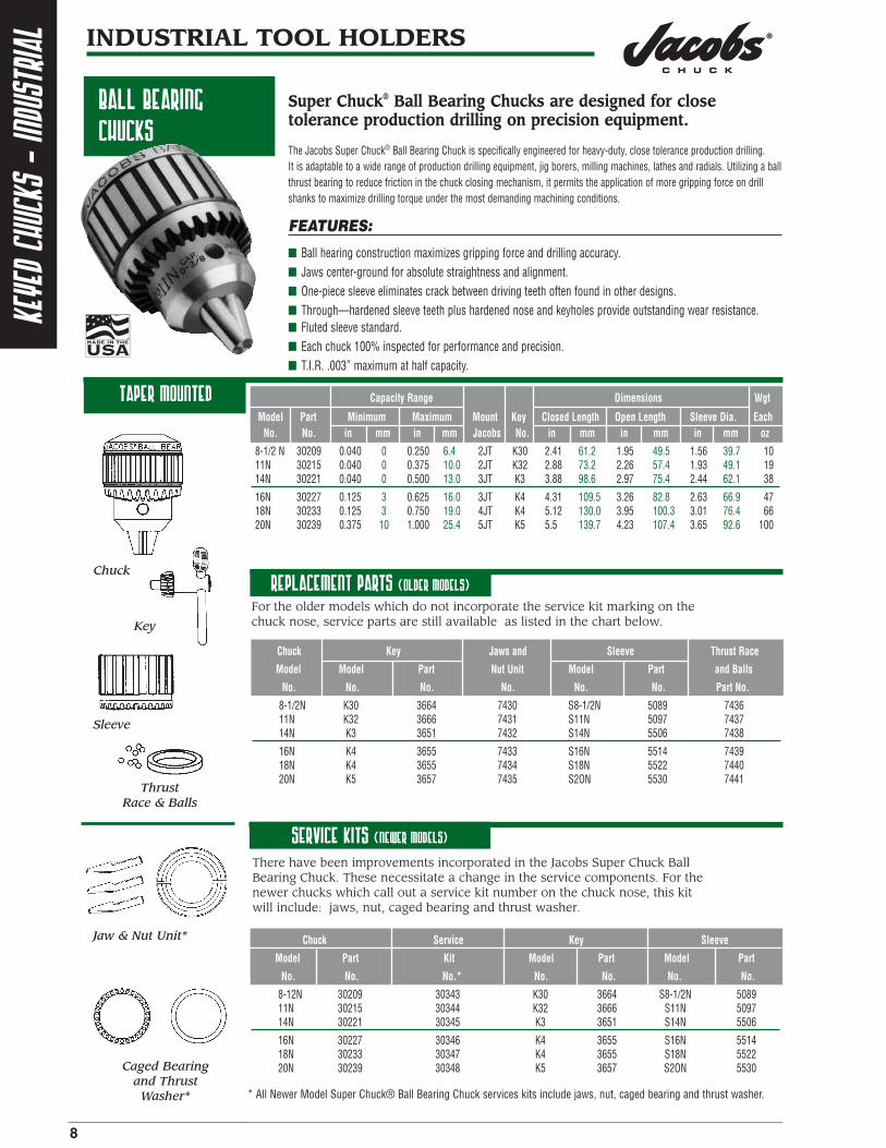
ball bearing chucks
taper mounted Capacity Range Dimensions Wgt
Model Part Minimum Maximum Mount Key Closed Length Open Length Sleeve Dia. EachNo. No. in mm in mm Jacobs No. in mm in mm in mm oz
8-1/2 N 30209 0.040 0 0.250 6.4 2JT K30 2.41 61.2 1.95 49.5 1.56 39.7 1011N 30215 0.040 0 0.375 10.0 2JT K32 2.88 73.2 2.26 57.4 1.93 49.1 1914N 30221 0.040 0 0.500 13.0 3JT K3 3.88 98.6 2.97 75.4 2.44 62.1 38
16N 30227 0.125 3 0.625 16.0 3JT K4 4.31 109.5 3.26 82.8 2.63 66.9 4718N 30233 0.125 3 0.750 19.0 4JT K4 5.12 130.0 3.95 100.3 3.01 76.4 6620N 30239 0.375 10 1.000 25.4 5JT K5 5.5 139.7 4.23 107.4 3.65 92.6 100
Chuck Key Jaws and Sleeve Thrust Race
Model Model Part Nut Unit Model Part and Balls
No. No. No. No. No. No. Part No.
8-1/2N K30 3664 7430 S8-1/2N 5089 743611N K32 3666 7431 S11N 5097 743714N K3 3651 7432 S14N 5506 7438
16N K4 3655 7433 S16N 5514 743918N K4 3655 7434 S18N 5522 744020N K5 3657 7435 S2ON 5530 7441
Replacement parts (older models)
For the older models which do not incorporate the service kit marking on thechuck nose, service parts are still available as listed in the chart below.
Service kits (newer models)
Chuck Service Key Sleeve
Model Part Kit Model Part Model Part
No. No. No.* No. No. No. No.
8-12N 30209 30343 K30 3664 S8-1/2N 508911N 30215 30344 K32 3666 S11N 509714N 30221 30345 K3 3651 S14N 5506
16N 30227 30346 K4 3655 S16N 551418N 30233 30347 K4 3655 S18N 552220N 30239 30348 K5 3657 S2ON 5530
There have been improvements incorporated in the Jacobs Super Chuck BallBearing Chuck. These necessitate a change in the service components. For thenewer chucks which call out a service kit number on the chuck nose, this kitwill include: jaws, nut, caged bearing and thrust washer.
* All Newer Model Super Chuck® Ball Bearing Chuck services kits include jaws, nut, caged bearing and thrust washer.
Super Chuck® Ball Bearing Chucks are designed for closetolerance production drilling on precision equipment.
The Jacobs Super Chuck® Ball Bearing Chuck is specifically engineered for heavy-duty, close tolerance production drilling. It is adaptable to a wide range of production drilling equipment, jig borers, milling machines, lathes and radials. Utilizing a ballthrust bearing to reduce friction in the chuck closing mechanism, it permits the application of more gripping force on drillshanks to maximize drilling torque under the most demanding machining conditions.
FEATURES:
■ Ball hearing construction maximizes gripping force and drilling accuracy.■ Jaws center-ground for absolute straightness and alignment.■ One-piece sleeve eliminates crack between driving teeth often found in other designs.■ Through—hardened sleeve teeth plus hardened nose and keyholes provide outstanding wear resistance. ■ Fluted sleeve standard.■ Each chuck 100% inspected for performance and precision.■ T.I.R. .003” maximum at half capacity.
Chuck
Key
Sleeve
Thrust Race & Balls
Jaw & Nut Unit*
Caged Bearingand Thrust
Washer*

keyedchucks
-industrial
9
INDUSTRIAL TOOL HOLDERS
PLAIN BEARING CHUCKS
taper mounted
Capacity Range Dimensions Wgt
Model Part Minimum Maximum Mount Key Closed Length Open Length Sleeve Dia. EachNo. No. in mm in mm Jacobs No. in mm in mm in mm oz
3A 6223 0.125 3 0.625 16.0 3JT K3 3.81 96.8 2.87 72.9 2.30 58.4 323KD (2) 6228 0.125 3 0.625 16.0 3JT K3 4.06 103.1 3.12 79.2 2.29 58.2 333PD (3) 6230 0.125 3 0.625 16.0 3JT K3 4.06 103.1 3.12 79.2 2.29 58.2 33
34-02 14442 .040 1 0.500 13.0 2JT K3 3.52 89.4 2.74 69.6 2.04 51.8 2334-06 6295 .040 1 0.500 13.0 6JT K3 3.52 89.4 2.74 69.6 2.04 51.8 2434-33 14445 .040 1 0.500 13.0 33JT K3 3.52 89.4 2.74 69.6 2.04 51.8 23
34-33C(4) 14451 .040 1 0.500 13.0 33JT K3C 3.71 94.2 2.93 74.4 2.00 50.8 2636 6309 0.18 0 0.800 20.3 3JT K4 4.06 103.1 3.14 79.8 2.54 64.5 4536KD (2) 14865 0.18 5 0.800 20.3 3JT K4 4.25 108.0 3.42 86.9 2.54 64.5 44
36PD (3) 14866 0.18 5 0.800 20.3 3JT K4 4.25 108.0 3.42 86.9 2.54 64.5 45
Heavy Duty Model■ Fluted sleeve standard except Model 34-33C, which is smooth and ground.
(2) Equipped with positive drive slot.(3) Equipped with pin type positive drive.(4) Equipped with locking collar - 1-1/16-20 thread, smooth sleeve.
MEDIUM DUTY MODEL■ Fluted sleeve standard except Models 0 and 1 A, which are smooth and ground.
■ All Series 33 Plain Bearing Chucks are hammer capable.
Capacity Range Dimensions Wgt
Model Part Minimum Maximum Mount Key Closed Length Open Length Sleeve Dia. EachNo. No. in mm in mm Jacobs No. in mm in mm in mm oz
0 6200 .0135 0 0.156 4.0 0JT KO 1.404 36.8 1.100 27.9 0.850 21.6 21A 6206 .040 1 0.250 6.5 1JT K1 1.920 48.8 1.540 39.1 1.180 30.0 52A 6214 .040 1 0.375 10.0 2JT K2 2.810 71.4 2170 55.1 1.670 42.4 13
31-01 14697 .040 1 0.375 10.0 1JT K30 2.490 63.2 2.010 51.1 1.420 36.1 831-02 14698 .040 1 0.375 10.0 2JT K30 2.490 63.2 2.010 51.1 1.420 36.1 833 6279 0.08 2 0.500 13.0 33JT K32 3.210 81.5 2.520 64.0 1.792 45.5 16
3326A 6291 0.08 2 0.500 13.0 .6250 K32 3.540 89.9 2.850 72.4 1.792 45.5 1733KD(3) 6281 0.08 2 0.500 13.0 33JT K32 3.460 87.9 2.770 70.4 1.792 45.5 17
(1) Model 0 has a minimum capacity of a No. 80 (.0135in/.344mm) drill.(2) Equipped with positive drive slot.
The O.E.M. standard for accuracy and durability on all types ofindustrial power and machine tools.
The Jacobs® Plain Bearing Chuck is the world’s most widely used for medium or heavy-duty portable, bench or floor mountedpower tools. This industrial quality chuck, with fully hardened and ground working components, offers exceptionally highaccuracy, gripping power and durability. Both heavy and medium duty models are available in a wide range of capacities foruse on threaded or taper mounted spindles.
FEATURES:
■ Heavy and Medium Duty models for threaded or taper mounting.■ Jaws center-ground for absolute straightness and alignment.■ One-piece sleeve eliminates crack between driving teeth often found in other designs.■ Through-hardened sleeve teeth, plus hardened nose and keyholes provide outstanding wear resistance.■ Each chuck 100% inspected for performance and precision.■ T.I.R. .004” maximum at half capacity.

keye
dch
ucks
-in
dust
rial
10
INDUSTRIAL TOOL HOLDERS
PLAIN BEARING CHUCKS (continued)
THREAD MOUNTED
Capacity Range Dimensions Wgt
Model Part Minimum Maximum Mount Key Closed Length Open Length Sleeve Dia. EachNo. No. in mm in mm Jacobs No. in mm in mm in mm oz
3B 5/8 6232 0.125 3 0.625 16.0 5/8-16 K3 3.81 97 2.84 72 2.29 58 327BA 3/8 6255 0 (1) 1 0.250 6.5 3/8-24 K7 2.23 57 1.74 44 1.33 34 732BA 1/2 8859 0 (1) 1 0.375 10.0 1/2-20 K32 3.05 77 2.31 59 1.79 45 14
35B 1/2 14723 0.156 4 0.625 16.0 1/2-20 K3 3.52 89 2.74 70 2.04 52 2536B 3/4 6316 0.188 5 0.800 20.3 3/4-16 K4 4.12 105 3.20 81 2.54 65 4636B 5/8 6314 0.188 5 0.800 20.3 5/8-16 K4 4.12 105 3.20 81 2.54 65 46
Heavy Duty Model■ Fluted sleeve standard on all models.
(1) At minimum capacity will hold a No. 60 (0.040in /1mm) drill.
Medium Duty Model■ Fluted sleeve standard except Models OB 5/16, 1B 3/8, AND 41BA 3/8-S, which are smooth and ground.■ 41 Series Chucks replace 31 series Chucks.
Light Duty Model■ Industrial Quality■ Through–hardened jaws provide hard, durable gripping forces.
Capacity Range Dimensions Wgt
Model Part Minimum Maximum Mount Key Closed Length Open Length Sleeve Dia. EachNo. No. in mm in mm Jacobs No. in mm in mm in mm oz
OB 5/16 6204 .0135 0 0.156 4.0 5/16-24 K0 1.53 39.0 1.17 30.00 0.85 22.0 21B 3/8 6208 .040 1 0.250 6.5 3/8-24 K1 1.95 50.0 1.57 40.00 1.12 28.0 52BA 3/8 6219 .040 1 0.375 10.0 3/8-24 K2 2.81 71.0 2.17 55.00 1.67 42.0 13
41BA 3/8 30728 .040 1 0.375 10.0 3/8-24 K30 2.50 63.5 2.05 52.07 1.43 36.3 841BA 3/8 - S 31138 .040 1 0.375 10.0 3/8-24 K30 2.50 63.5 2.05 52.07 1.43 36.3 841BA 1/2 31090 .040 1 0.375 10.0 1/2-20 K30 2.50 63.5 2.05 52.07 1.43 36.3 8
33BA 1/2 6287 0.08 2 0.500 13.0 1/2-20 K32 3.09 78.0 2.43 62.00 1.79 45.0 1733BA 3/8 6283 0.08 2 0.500 13.0 3/8-24 K32 3.09 78.0 2.43 62.00 1.79 45.0 1733BA 5/8 6289 0.08 2 0.500 13.0 5/8-16 K32 3.09 78.0 2.43 62.00 1.79 45.0 17
Capacity Range Dimensions Wgt
Model Part Minimum Maximum Mount Key Closed Length Open Length Sleeve Dia. EachNo. No. in mm in mm Thread No. in mm in mm in mm oz
22BA 3/8 14943 .063 1.6 0.375 10 3/8-24 KK 2.42 61.5 1.89 48.0 1.42 36.1 824BA 3/8 14946 .063 1.6 0.500 13 3/8-24 KK 3.00 76.2 2.30 58.4 1.72 43.6 1326BA 1/2 14947 .063 1.6 0.500 13 1/2-20 KK 3.00 76.2 2.30 58.4 1.72 43.6 13
Replacement parts
Chuck Jaw and Nut Unit Sleeve
Series Model Part Model Part
No. No. No. No. No.
34 U34 7424 S34 504633 U33 7423 S33 50163 U3 7417 S3 4944
36 U36 7425 S36 5066
SleeveJaw & Nut Unit*
(1) At minimum capacity will hold a No. 60 (0.040in/mm) drill.(2) Model OB 15/16 has a minimum capacity of a No. 80 (.0135in/.344mm) drill.(S) Smooth Sleeve

INDUSTRIAL TOOL HOLDERS
INDUSTRIAL KEYLESSCHUCKS
11
keylesschucks
-industrial
High Precision Modeltaper mounted
High Torque/ High Precision Model
Precision design combines keyless operation with the ultimate in drill chuck accuracy.Jacobs® Industrial Keyless Chucks are high precision devices specifically designed for high accuracy applications on eitherconventional or CNC equipment. Tightened and released by hand,they permit more rapid tooling changes to increase machining productivity. A self-tightening feature produces significantly higher gripping force to resist tool shank slippage.Precision manufactured and tested to the most exacting quality standards, Jacobs® Industrial Keyless Chucks can be countedon for extremely high reliability and durability under the most demanding machining conditions.
FEATURES:
■ Precision tested and certified to .0016" T.l.R. maximum at half capacity.■ Self-tightening feature automatically increases gripping force proportional
to increased torque to prevent tool shank slippage.■ All components exposed to wear are completely hardened to maintain accuracy and extend chuck life.■ Jacobs® taper mount permits use on a wide range of high accuracy drill presses, jig borers,
milling machines and production drilling equipment
Capacity Range* Dimensions Wgt
Model Part Minimum Maximum Mount Closed Lgth (A) Open Lgth (A-1) Sleeve Dia. (D) EachNo. No. in mm in mm Jacobs in mm in mm in mm oz
JKP 03-J0 31126 0.000 0 0.118 3.0 0JT 1.87 47.5 1.73 44 0.96 24.5 4JKP 03-J1 31127 0.000 0 0.118 3.0 1JT 1.87 47.5 1.73 44 0.96 24.5 4JKP 03-5/16 31128 0.000 0 0.118 3.0 5/16-24 1.87 47.5 1.73 44 0.96 24.5 4JKP 65-J1 31121 0.012 .300 0.255 6.5 1JT 2.76 70 2.44 62 1.28 32.5 11JKP 80-J2S 9679 0.012 .300 0.315 8.0 2JS* 2.91 74 2.64 67 1.46 37.0 14JKP 100-J2 9681 0.020 .500 0.394 10.0 2JT 3.50 89 3.19 81 1.61 41.0 22JKP 100-J33 9680 0.020 .500 0.394 10.0 33JT 3.50 89 3.19 81 1.61 41.0 22JKP 130-J2 9683 0.039 1.000 0.512 13.0 2JT 3.90 99 3.46 88 1.81 46.0 32
JKP 130-J33 9682 0.039 1.000 0.512 13.0 33JT 3.90 99 3.46 88 1.81 46.0 20 JKP 130-J6 9684 0.039 1.000 0.512 13.0 6JT 3.90 99 3.46 88 1.81 46.0 20JKP 160-J6 9685 0.118 3.000 0.630 16.0 6JT 4.21 107 3.74 95 2.17 55.0 42
* S - Short Taper
JKP
JKT
■ Precision tested and certified to .0016" T.I.R. maximum at half capacity.■ For use on CNC machining centers in drilling, boring, counter-boring and milling operations
requiring heavy penetration.■ Furnished with milled wrench flats and spanner wrench to allow the application of supplementary gripping
torque. Light tightening increases gripping torque up to 3 times higher than hand tightening.■ Resists tool loosening on high-speed machines with right hand rotation and instant spindle stop.
■ For general machining applications
Capacity Range* Dimensions Wgt
Model Part Minimum Maximum Mount Closed Lgth (A) Open Lgth (A-1) Sleeve Dia. (D) EachNo. No. in mm in mm Jacobs in mm in mm in mm oz
JKT65-J1 31122 0.000 0 0.255 6.5 1JT 2.76 70 2.44 62 1.28 32.5 11JKT80-J2S 30526 0.000 0 0.315 8.0 2JTS* 2.91 74 2.64 67 1.46 37.0 14JKT 100-J33 30532 0.000 0 0.394 10.0 33JT 3.50 89 3.19 81 1.61 41.0 22JKT 100-J2 30533 0.000 0 0.394 10.0 2JT 3.50 89 3.19 81 1.61 41.0 22JKT 130-J2 30527 0.039 1 0.512 13.0 2JT 3.90 99 3.46 88 1.81 46.0 32JKT 130-J33 30528 0.039 1 0.512 13.0 33JT 3.90 99 3.46 88 1.81 46.0 32JKT 130-J6 30529 0.039 1 0.512 13.0 6JT 3.90 99 3.46 88 1.81 46.0 32JKT16O-J6 30530 0.118 3 0.630 16.0 6JT 4.21 107 3.74 95 2.17 55.0 42
* S - Short Taper

INDUSTRIAL TOOL HOLDERS
12
Keyl
ess
chuc
ks-
indu
stri
al
High Torque / High Precision
keyless chucks withintegrated shank
Capacity Range Dimensions Weight
Model Part Minimum Maximum Mount Closed Length Open Length Sleeve Dia. Ea.
No. No. in mm in mm Jacobs in mm in mm in mm oz
JK 80-MT2 31406 0.000 0 0.315 8.0 MT2 2.83 72 2.56 65 1.50 38 28JK 100-MT2 31407 0.000 0 0.394 10.0 MT2 3.23 82 2.87 73 1.69 43 36JK 130-MT2 31408 0.039 1 0.512 13.0 MT2 3.62 92 3.15 80 1.89 48 42JK 130-MT3 31409 0.039 1 0.512 13.0 MT3 3.62 92 3.15 80 1.89 48 47JK 130-MT4 31410 0.039 1 0.512 13.0 MT4 3.54 90 3.23 82 1.89 48 56JK 130-R8 31411 0.039 1 0.512 13.0 R8 3.54 90 3.23 82 1.89 48 56JK 130-5-8" 31412 0.039 1 0.512 13.0 5/8 3.62 92 3.15 80 1.89 48 42JK 160-MT2 31413 0.118 3 0.630 16.0 MT2 3.78 96 3.35 85 2.13 54 56JK 160-MT3 31414 0.118 3 0.630 16.0 MT3 3.78 96 3.35 85 2.13 54 61JK 160-MT4 31415 0.118 3 0.630 16.0 MT4 3.78 96 3.35 85 2.13 54 70JK 160-R8 31416 0.118 3 0.630 16.0 R8 3.78 96 3.35 85 2.13 54 63
FEATURES:■ High precision keyless drill chuck – arbor is integrated into the internal socket of the drill chuck.
■ This integrated design makes it impossible for the arbor and the drill chuck to become accidently separated, providinga unit of greater rigidity and precision. As a result of its compact design, accumulated run-out is reduced to a minimum.
■ Self-tightening feature automatically increases gripping force proportional to increased torque to prevent toolshank slippage. For right-hand rotation applications only.
■ 100% individually controlled to ensure not to exceed a maximum total integrated run-out of 0.04 mm.
■ Mounts available: Morse tapers, straight shanks and R-8.
Medium DutyIndustrial KeylessChucks
Capacity Range Dimensions Weight
Model Part Minimum Maximum Mount Closed Length Open Length Sleeve Dia. Ea.
No. No. in mm in mm Jacobs in mm in mm in mm oz
JK 80 3/8 33356 0.000 0 0.315 8.0 3/8-24 2.68 68 2.40 61 1.34 34 11JK 80 J1 33357 0.000 0 0.315 8.0 1JT 2.68 68 2.40 61 1.34 34 11JK 80 J2 33358 0.000 0 0.315 8.0 2JT 2.68 68 2.40 61 1.34 34 11JK 100 3/8 33359 0.000 0 0.394 10.0 3/8-24 3.15 80 2.87 73 1.54 39 16JK 100 1/2 33360 0.000 0 0.394 10.0 1/2-20 3.15 80 2.87 73 1.54 39 16JK 100 J2 33361 0.000 0 0.394 10.0 2JT 3.15 80 2.87 73 1.54 39 16JK 130 3/8 33362 0.039 1 0.512 13.0 3/8-24 3.74 95 3.39 86 1.73 44 23JK 130 1/2 33363 0.039 1 0.512 13.0 1/2-20 3.74 95 3.39 86 1.73 44 22JK 130 J33 33364 0.039 1 0.512 13.0 33JT 3.74 95 3.39 86 1.73 44 22JK 130 J2 33365 0.039 1 0.512 13.0 2JT 3.74 95 3.39 86 1.73 44 22JK 130 J6 33366 0.039 1 0.512 13.0 6JT 3.74 95 3.39 86 1.73 44 23JK 160 1/2 33367 0.118 3 0.630 16.0 1/2-20 4.53 115 4.02 102 2.01 51 39JK 160 5/8 33368 0.118 3 0.630 16.0 5/8-16 4.53 115 4.02 102 2.01 51 37JK 160 J33 33369 0.118 3 0.630 16.0 33JT 4.53 115 4.02 102 2.01 51 37JK 160 J6 33370 0.118 3 0.630 16.0 6JT 4.53 115 4.02 102 2.01 51 38JK 200 J3 33371 0.197 5 0.787 20.0 3JT 5.51 140 4.02 102 2.52 64 77
FEATURES:■ Drill chucks for industrial use (medium duty), available with screw fittings for professional portable
drilling machines and with taper fittings for stationary drilling machines.
■ Automatic fitting for efficient, fast change of tools.
■ Self-tightening mechanism automatically increases the grip in proportion to the increase in torque duringthe drilling and avoids the tool slipping in a clockwise rotation.
■ Fits tools of up to 20mm in diameter.
■ Machine fitting via DIN0238 of Jacobs tapers and UNF thread fittings.

13
Keylesschucks
-industrial
INDUSTRIAL TOOL HOLDERS
INDUSTRIAL KEYLESS CHUCKSWITH V-FLANGEMOUNTS
cat-v flange
BT Flange
Designed to maximize drill chuck rigidity and precision onmachining centers with automatic tool changers.
FEATURES:
■ Choice of CAT-V flange or BT flange with Jacobs® High Torque/High Precision Keyless Chucks.
■ Single taper connection eliminates intermediate arbors to assure high tool rigidity and drilling
■ Compact design, as compared to conventional tool setups, increases machining flexibility.
■ Precision tested and individually certified for run-out (mounting taper to chuck capacity).
Capacity Range Dimensions Wgt
Model Part Minimum Maximum Taper Closed Lgth (A) Open Lgth (A-1) Sleeve Dia. (D) EachNo. No. in mm in mm Size in mm in mm in mm oz
JKC 80-30 30551 0.000 0 0.315 8 30 4.21 107 3.98 101 1.46 37 30JKC 80-40 30552 0.000 0 0.315 8 40 3.46 88 3.23 82 1.46 37 45JKC 130-40 30553 0.039 1 0.512 13 40 4.96 126 4.53 115 1.89 48 66
JKC130-45 30554 0.039 1 0.512 13 45 5.16 131 4.72 120 2.17 55 79JKC 130-50 30555 0.039 1 0.512 13 50 4.21 107 3.78 96 1.89 48 87JKC160-40 30556 0.118 3 0.630 16 40 4.21 107 3.78 96 1.89 48 129
JKC160-50 30557 0.118 3 0.630 16 50 4.13 105 3.70 94 2.17 55 135
Capacity Range Dimensions Wgt
Model Part Minimum Maximum Taper Closed Lgth (A) Open Lgth (A-1) Sleeve Dia. (D) EachNo. No. in mm in mm Size in mm in mm in mm oz
JKB 80-30 30536 0.000 0 0.315 8 30 2.87 73 3.11 79 1.46 37 23JKB 80-40 30537 0.000 0 0.315 8 40 3.14 80 2.84 72 1.46 37 44JKB 80-40L* 30538 0.000 0 0.315 8 40 4.25 108 4.49 114 1.46 37 53JKB 130-40 30539 0.039 1 0.512 13 40 3.39 86 3.82 97 1.89 48 54JKB 130-40L* 30540 0.039 1 0.512 13 40 5.35 136 5.79 147 1.89 48 81JKB 160-40 30541 0.118 3 0.630 16 40 4.13 105 4.57 116 2.17 55 68JKB 130-45 30542 0.039 1 0.512 13 45 3.62 92 4.06 103 1.89 48 85JKB 130-50 30543 0.039 1 0.512 13 50 3.82 97 4.25 108 1.89 48 146JKB 160-50 30544 0.118 3 0.630 16 50 3.74 95 4.17 106 2.17 55 151JKB 160-50L* 30545 0.118 3 0.630 16 50 5.71 145 6.14 156 2.17 55 185* "L" indicates additional length.
WARNING -
Toolholder retention studs are not necessarily interchangeable across various types of toolholders or machine tool models. Use of metric threaded studs in inch threaded holders or vice versa is dangerous. Failure to use the proper thread or stud configuration can cause the toolholder to come free of the spindle resulting in serious personal injury.
JKC
JKB
■ Meets ANSI/ASME Standard B5.50—1 994.
■ Precision tested and certified to .0016" T.l.R. maximum at half capacity (mounting taper to chuck capacity).
■ Meets JMBTA Standard MAS 403—1982.
■ Precision tested and certified to .0016" T.I.R. maximum at half capacity (mounting taper to chuck capacity).
■ Internal Thread M16 x 2.0.

14
INDUSTRIAL TOOL HOLDERS
TOOLHOLDER/ADAPTERS
TOOL
HOLD
ER/
ADAP
TERS
cat-v flange tojacobs® TAPER ARBOR
BT flange tojacobs® TAPER ARBOR
For use on machining centers with automatictool changers. Choice of CAT-V flange or BTflange to Jacobs® taper arbor.
■ Meets ANSl/ASME Standard B5.50—1994. ■ 5/8–11 Internal Thread.
Dimensions Wgt
Model Part Taper Mount A B C EachNo. No. Size Jacobs in mm in mm in mm oz
JCJ 30-J2 30566 30 J2 2.41 61.2 1.38 35.1 1.25 31.8 18JCJ 30-J3 30567 30 J3 2.75 69.9 1.38 35.1 1.25 31.8 18JCJ 30.J33 30568 30 J33 2.53 64.3 1.38 35.1 1.25 31.8 18JCJ 30-J6 30569 30 J6 2.53 64.3 1.38 35.1 1.25 31.8 18JCJ 40-J2 30570 40 J2 2.41 61.2 1.38 35.1 1.75 44.5 37JCJ 40-J3 30571 40 J3 2.75 69.9 138 35.1 1.75 44.5 37JCJ 40-J33 30572 40 J33 2.53 64.3 1.38 35.1 1.75 44.5 37JCJ 40-J4 30573 40 J4 3.19 81.0 1.38 35.1 1.75 44.5 37JCJ 40-J6 30574 40 J6 2.53 64.3 1.38 35.1 1.75 44.5 37JCJ 45-J3 30575 45 J3 2.75 69.9 138 35.1 2.25 57.2 70JCJ 45-J33 30576 45 J33 2.53 64.3 1.38 35.1 2.25 57.2 70JCJ 45-J4 30577 45 J4 3.19 81.0 1.38 35.1 2.25 57.2 70JCJ 45oJ5 30578 45 J5 3.41 86.6 1.38 35.1 2.25 57.2 70JCJ 50-J3 30579 50 J3 2.75 69.9 1.38 35.1 2.75 69.9 109JCJ 50-J4 30580 50 J4 3.19 81.0 1.38 35.1 2.75 69.9 109JCJ 50-J5 30581 50 J5 3.41 86.6 1.38 35.1 2.75 69.9 109
■ Meets JMBTA Standard MAS 403—1982. ■ 5/8–11 Internal Thread.
Dimensions Wgt
Model Part Taper Mount A B C EachNo. No. Size Jacobs in mm in mm in mm oz
JBT 30-J2 30582 30 J2 2.27 57.7 1.36 34.5 1.25 31.8 18JBT 30-J3 30583 30 J3 2.61 66.3 1.36 34.5 1.25 31.8 18JBT 30-J33 30584 30 J33 2.39 60.7 1.36 34.5 1.25 31.8 18JBT 30-J6 30585 30 J6 2.39 60.7 1.36 34.5 1.25 31.8 18JBT 40-J2 30586 40 J2 2.09 53.1 1.18 30.0 2.48 63.0 37JBT 40-J3 30587 40 J3 2.43 61.7 1.18 30.0 2.48 63.0 37JBT 40-J33 30588 40 J33 2.21 56.1 1.18 30.0 2.48 63.0 37JBT 40-J4 30589 40 J4 2.87 72.9 1.18 30.0 2.48 63.0 37JBT 40-J6 30590 40 J6 2.21 56.1 1.18 30.0 2.48 63.0 37JBT 45-J3 30591 45 J3 2.67 67.8 1.42 36.1 3.34 84.8 78JBT 45-J33 30592 45 J33 2.45 62.2 1.42 36.1 3.34 84.8 78JBT 45-J4 30593 45 J4 3.11 79.0 1.42 36.1 3.34 84.8 78JBT 45-J5 30524 45 J5 3.33 84.6 1.42 36.1 3.35 85.0 78JBT 50-J3 30595 50 J3 2.87 72.9 1.62 41.1 3.94 100.1 131JBT 50-J4 30596 50 J4 3.31 84.1 1.62 41.1 3.94 100.1 131JBT5O-J5 30597 50 J5 3.53 89.7 1.62 41.1 3.94 100.1 131
WARNING -
-Toolholder retention studs are not necessarily interchangeable across various types of toolholders or machine tool models. Use of metric threaded studs in inch threaded holders or vice versa is dangerous. Failure to use the proper threador stud configuration can cause the toolholder to come free of the spindle resulting in serious personal injury.
JCJ
JBT

15
tap&
diegrinder
chucksINDUSTRIAL TOOL HOLDERS
tapchucks
die grinder chucks
REPLACEMENT PARTS
NUT FOR DIE GRINDER CHUCK*
Simplify tap changing and provide unmatched accuracy.
FEATURES:
■ Designed for use with the versatile Jacobs® Rubber-Flex® Collet which accepts and precisely centers both decimal and metric shank diameters.*
■ Simple operation — one quarter turn of chuck screw allows nut to disengage back jaws. Tap shank sightinghole presents full view of tap square during changeovers.
■ Each chuck, with one interchangeable Rubber--Flex® Collet, handles a wide range of tap sizes to speed tap size changes.
■ Positive-drive chuck jaws always locate square of tap shank to ensure superior performance.
■ Available with choice of Jacobs®, round or square hole mounts. *Refer to Rubber-Flex® Collet information.Overall Round Shank
Length@ Maximum Capacity Available Wgt
Model Part Tap Capacity Mount Max Cap Diameter Minimum Maximum Rubber-Flex® Ea.
No. No. in mm Style in mm in mm in mm in mm Collets † oz
41-01 14121 #0-1/4 1.00-6.35 1JT* 2.00 50.7 0.84 21 0.09 2 0.25 6 J116,J117 242-01 14123 #10-5/16 4.83-7.94 1JT* 2.60 65.0 1.06 27 0.09 2 0.38 10 J420,J421, J422,J423 642-02 14125 #10-5/16 4.83-7.94 2 short JT* 2.50 64.2 1.06 27 0.09 2 0.38 10 J420,J421.J422, J423 542-24 14129 #10-5/16 4.83-7.94 .3675 Dia. 2.60 66.0 1.06 27 0.09 2 0.38 10 J420,J421,J422, J423 642-J8 14127 #0-1/4 1.00-6.35 .375 Sq. Hole 2.40 61.2 1.06 27 0.09 2 0.38 10 J420,J421, J422.J423 644-02 14131 5/16-1/2 7.94-15.88 2JT* 3.12 79 1.47 37 0.11 3 0.50 13 J440,J441,J443 1244-J9 14135 #10-1/2 4.83-12.70 .500 Sq. Hole 3.12 79 1.47 37 0.11 3 0.50 13 J440.J441.J443 12
*Jacobs® Taper† Rubber-Rex CoIlets are not included. Must be ordered separately.
Nut Back Jaws
Rubber-Flex® Collets
Model Rubber-Flex® Back Nut BodyNo. Nut Collet Jaws Wrench Wrench
41-01 12792 J116, J117 6656 1848 184942-01 12793 J420.J421.J422.J423 6654 1850 185142-02 12793 J420.J421,J422,J423 6654 1850 185142-J8 12793 J420,J421,J422.J423 6654 1850 None42-24 12793 J420.J421J422,J423 6654 1850 1851
Compact tap chuck designed for use with Rubber-Flex® Collets holds mounted grinding burrs and rotary files on pneumatic andelectric die grinders.
FEATURES:
■ Compact design facilitates use for a wide range of applications.
■ Integral seal protects collet components from abrasives and swarf.
■ Rubber-Flex® Collets (see Rubber-Flex® information) furnished separately for tools with collet seating cones built into spindles.
Capacity Range* Dimensions Wgt
Model Part Minimum Maximum Mount Closed Lgth Open Lgth Sleeve Dia. EachNo. No. in mm in mm Jacobs in mm in mm in mm oz
100-61 9756 0.09 2.3 0.25 6.4 3/8-24 1.77 45.0 1.88 47.8 0.75 19.1 1.5
Model PartNo. No.
N100 12791*Nut for Die Grinder Chuck, Model No. 100-61.

16
INDUSTRIAL TOOL HOLDERS
rubber-flex®
collets
tap chuck collets
rubb
er-f
lex®
coll
ets
Jacobs® Rubber-Flex collets outperform conventional split-steel collets in gripping power, accuracy and durability.
Unique in design and operation, the Jacobs® Rubber-Flex® Collet can generate two to three timesthe gripping power of a conventional split-steel collet. Gripping force is uniform and parallelthroughout the collet contact length and not concentrated at the nose or back as is frequently thecase with split-steel collets (see illustration below). Construction is of durable synthetic rubbercompound permanently bonded to hardened steel jaw insert surfaces and through-holes. It is unaffected by heat, coolants and cutting compounds and retains its flexibility over a long servicelife as compared to spring tempered metal designs.
FEATURES:
■ Parallel jaw insert surfaces exert uniform, accurate gripping force up to three times greater than can be achieved with split-steel collets.
■ Each collet accepts and precisely centers a wide range of both decimal or metric diameters(within individual capacity ranges) to speed setups and increase machining productivity
■ Durable one-piece construction. Synthetic rubber retains flexibility and resists deterioration from heat, coolants and cutting compounds.
■ Steel jaw inserts precision ground (after molding process) to assure maximum gripping accuracy (parallelism). Hardened for greater wear resistance than split steel collets.
■ Each collet bore is held concentric to the O.D. tapers, both front and back, to minimize T.J.R.
■ Automatically seals tool O.D. to permit coolant flow through tool reducing wear.
■ Seals collets and machine spindles to protect from abrasive particles and swarf.
Rubber-Flex® ColletUndersized BarOversized Bar
Conventional split-steel collets provide maximum gripping efficiency only at actual bored or nominal capacity They lose parallelism when chucking bars even a few thousandths over or under this capacity. This significantly reduces grippingstrength and accuracy. Rubber-Flex Collets exert uniform gripping pressure throughout the collet contact length (within individual collet capacity ranges) regardless of bar tolerance deviations.
Rubber-Flex® Collets vs.Conventional Collets
Capacity Range (A) Contact Cone Outside Number Wgt
Model Part Minimum Maximum Length (B) Angle (C) Diameter (D) of EachNo. No. in mm in mm in mm deg. in mm inserts oz
J116 9757 0.100 2.4 0.177 4.5 0.468 11.9 26 0.590 15.1 6 0.10J117 9758 0.177 4.5 0.256 6.5 0.468 11.9 26 0.590 15.1 8 0.10J420 9747 0.176 4.5 0.320 8.1 0.500 12.7 40 0.941 23.9 6 0.20J421 9748 0.139 3.5 0.257 6.5 0.500 12.7 40 0.941 23.9 6 0.20J422 9751 0.253 6.4 0.383 9.7 0.500 12.7 40 0.941 23.9 6 0.30J423 9817 0.090 2.3 0.180 4.6 0.500 12.7 40 0.860 21.8 4 0.30J440 9749 0.280 7.1 0.500 12.7 0.630 16.0 45 1.296 32.9 6 0.30J441 9750 0.176 4.5 0.383 9.7 0.630 16.0 45 1.296 32.9 6 0.30J443 9867 0.110 2.8 0.280 7.1 0.620 15.7 45 1.180 30.0 4 0.30

17
rubber-flex®
colletsINDUSTRIAL TOOL HOLDERS
rubber-flex®
collets (continued)
die grinder collets
lathe Chuck collets
Capacity Range (A) Contact Cone Outside Number Wgt
Model Part Minimum Maximum Length (B) Angle (C) Diameter (D) of EachNo. No. in mm in mm in mm deg. in mm inserts oz
J116 9757 0.094 2.4 0.177 4.5 0.468 11.9 26 0.59 15.1 6 0.1J117 9758 0.177 4.5 0.256 6.5 0.468 11.9 26 0.59 15.1 8 0.1
■ Collets J910, J911 and J912 have a contact length of .90 in. (23mm). All other lathe chuck collets have full length contact.
Capacity Range (A) Contact Cone Outside Clearance Number Wgt
Model Part Minimum Maximum Length (B) Angle (C) Diameter (D) Diameter (E) of Each
No. No. in mm in mm in mm deg. in mm in mm inserts oz
J910 9555 0 060 1.5 0.125 3.2 1.74 44.5 26 2.25 57 0.6 15.2 4 0.53J911 9556 0.125 3.2 0.250 6.4 1.74 44.5 26 2.25 57 0.6 15.2 6 0.53J912 9557 0.250 6.4 0.375 9.5 1.74 44.5 26 2.25 57 0.6 15.2 6 0.47J913 9558 0.375 9.5 0.500 12.7 1 74 44.5 26 2.25 57 — — 8 0.47J914 9559 0.500 12.7 0.625 15.9 1.74 44.5 26 2.25 57 — — 10 0.47J915 9560 0.625 15.9 0.750 19.1 1.74 44.5 26 2.25 57 — — 10 0.47J916 9561 0.750 19.1 0.875 22.2 1.74 44.5 26 2.25 57 — — 12 0.47J917 9562 0.875 22.2 1.000 27.9 1.74 44.5 26 2.25 57 — — 16 0.55J918 9563 1.000 25.4 1.125 28.6 1.74 44.5 26 2.25 57 — — 20 0.52J919 9564 1.125 28.6 1.250 31.8 1.74 44.5 26 2.25 57 — — 24 0.43J920 9565 1.250 31.8 1.375 34.9 1.74 44.5 26 2.25 57 — — 24 0.40J921* 9567 1.375 34.9 1.500 38.1 1.74 44.5 26 2.25 57 — — 24 0.27
Requires special 1-1/2" nose.

18
INDUSTRIAL TOOL HOLDERS
ARBORS
ARBO
RS
morse taper jacobs® TAPER ARBOR
Precision CNC machined and ground to ensure high accuracyand close-tolerance fit.
FEATURES:
■ Precision machined and ground to master gages for maximum performance with Jacobs® drill and tap chucks.
■ Adapt Jacobs® taper to: Morse tapers, straight shanks, threaded shanks and Bridgeport® tapers.
■ Each chuck, with one interchangeable Rubber--Flex® Collet, handles a wide range of tap sizes to speed tap size changes.
■ Ideal for use with custom tool and work holder designs and for specialized machining applications.
AO Part Overall Length Weight Ea.
No. No. Description in mm oz
AO101 7299 1 Morse X 1JT 3.38 85.7 2AO102 7300 1 Morse x 2 JT 3.59 91.3 2AO106 7303 1 Morse x 6JT 3.72 94.5 4AO133 7304 1 Morse x 33JT 3.72 94.5 3AO201 7306 2 Morse x 1JT 3.94 100.0 4AO202 7307 2 Morse x 2JT 4.16 105.6 5AO203 7308 2 Morse x 3JT 4.50 114.3 7AO204 7309 2 Morse x 4JT 4.94 125.4 12AO206 7311 2 Morse x 6JT 4.28 108.7 5AO233 7312 2 Morse x 33JT 4.28 108.7 5AO301 7313 3 Morse x 1JT 4.69 119.1 10AO302 7314 3 Morse x 2JT 4.94 125.4 10AO303 7315 3 Morse x 3JT 5.27 133.8 12AO304 7316 3 Morse x 4JT 5.70 144.9 17AO305 7317 3 Morse x 5JT 5.94 150.8 23AO306 7318 3 Morse x 6JT 5.06 128.6 11AO333 7319 3 Morse x 33JT 5.06 128.6 11AO402 7320 4 Morse x 2JT 5.91 150.0 21AO403 7321 4 Morse x 3JT 6.25 158.8 23AO404 7322 4 Morse x 4JT 6.69 169.9 30AO405 7323 4 Morse x 5JT 6.91 175.4 35AO406 7324 4 Morse x 6JT 6.03 153.2 21AO433 7325 4 Morse x 33JT 6.06 154.0 22AO503 7327 5 Morse x 3JT 7.50 190.5 53AO504 7328 5 Morse x 4JT 7.94 201.6 58AO505 7329 5 Morse x 5JT 8.16 207.2 65
STRAIGHT SHANK TOjacobs® TAPER
Dimensions Weight
AO Part Straight Shanks (L-1) Overall Length (L) Ea.
No. No. Description in mm in mm oz
A4000 7348 1/2" x 0JT 2.500 63.5 3.094 78.6 2A4001 7349 1/2" x 1JT 2.500 63.5 3.312 84.1 2A4002 7350 1/2" x 2JT 2.500 63.5 3.531 89.7 2A4003 7351 1/2" x 3JT 2.500 63.5 3.875 98.4 4A4006 7353 1/2" x 6JT 2.500 63.5 3.656 92.9 4A4033 7354 1/2" x 33JT 2.500 63.5 3.656 92.9 4A4101 7355 5/8" x 1JT 2.500 63.5 3.312 84.1 4A4102 7356 5/8" x 2JT 2.500 63.5 3.531 89.7 5A4103 7357 5/8" x 3JT 2.500 63.5 3.875 98.4 6A4106 7359 5/8" x 6JT 2.500 63.5 3.656 92.9 5A4133 7360 5/8" x 33JT 2.500 63.5 3.656 92.9 5A4202 7361 3/4" x 2JT 3.000 76.2 4.031 102.4 6A4203 7362 3/4" x 3JT 3.000 76.2 4.375 111.1 7A4206 7364 3/4" x 6JT 3.000 76.2 4.156 105.6 6A4233 7365 3/4" x 33JT 3.000 76.2 4.156 105.6 6A4303 7367 1" x 3JT 3.000 76.2 4.375 111.1 11A4306 7368 1" x 6JT 3.000 76.2 4.156 105.6 10
19
ARBORSINDUSTRIAL TOOL HOLDERS
arbors
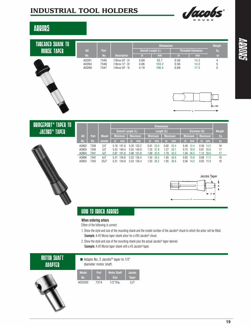
Threaded shank toMorse taper
Bridgeport® taper tojacobs® taper
Motor shaft adapter
HOW TO ORDER ARBORS
Dimensions Weight
AO Part Overall Length (L) Threaded Extension Ea.
No. No. Description in mm in mm oz
A0261 7345 2 Morse 3/8" - 24 3.69 93.7 0.56 14.3 4A0264 7346 2 Morse 1/2" - 20 4.06 103.2 0.56 14.3 5A0268 7347 2 Morse 5/8" - 16 4.19 106.4 0.69 17.5 5
Dimensions
Overall Length (L) Length (C) Diameter (D) Weight
AO Part Mount Minimum Maximum Minimum Maximum Minimum Maximum Ea.
No. No. Jacobs in mm in mm in mm in mm in mm in mm oz
AO802 7339 2JT 5.18 131.6 5.20 132.2 0.91 23.0 0.92 23.4 0.49 12.4 0.56 14.2 16AO803 7340 3JT 5.53 140.4 5.55 140.9 1.25 31.8 1.27 32.1 0.75 18.9 0.81 20.6 17AO804 7341 4JT 5.97 151.6 5.98 151.8 1.69 42.9 1.70 43.2 1.04 26.3 1.12 28.6 17AO806 7342 6JT 5.31 134.8 5.33 135.4 1.03 26.2 1.05 26.6 0.62 15.8 0.68 17.2 16AO833 7343 33JT 5.31 134.8 5.33 135.4 1.03 26.2 1.05 26.6 0.56 14.2 0.62 15.9 16
Model Part Motor Shaft Jacobs
No. No. Size Taper
AD2502 7374 1/2”Dia. 2JT
When ordering arborsEither of the following is correct:1. Show the style and size of the mounting shank and the model number of the Jacobs® chuck to which the arbor will be fitted.
Example: A #2 Morse taper shank arbor for a #34 Jacobs® chuck2. Show the style and size of the mounting shank plus the actual Jacobs® taper desired.
Example: A #2 Morse taper shank with a #3 Jacobs® taper.
■ Adapts No. 2 Jacobs® taper to 1/2” diameter motor shaft.

20
INDUSTRIAL TOOL HOLDERS
DRILL SLEEVES AND EXTENSION SOCKETS
drill sleeves-morse taper
extension sockets - morse taper
Archer precision machine tool accessories for maximum flexibility in tooling setups.
Series 600 Series 700 Dimensions Weight
Model Part Model Part Morse Taper No. Overall Length (L) Ea
No No No No Outside Inside in mm oz
610 30421 710 30432 1 0 3.125 79 1621 30422 2 1 3.62 92 2632 30423 732 30434 3 2 4.38 111 5631 30424 3 1 3.88 98 6643 30425 743 30436 4 3 5.50 140 13642 30426 742 30437 4 2 4.88 124 14641 30427 4 1 4.88 124 17651 30638 751 30762 5 1 6.12 156 47654 30428 754 30439 5 4 6.69 170 35653 30429 753 30440 5 3 6.12 156 41652 30430 752 30441 5 2 6.12 156 46664 30639 764 30822 6 4 8.56 217 88665 30431 6 5 8.56 217 90
Archer® Series 600 and 700
FEATURES:
■ Adapt smaller Morse taper shank tools to larger machine spindles.
■ Oil toughened and externally precision ground with hardened tang.
■ Outside Morse taper sizes are 1 through 6; inside Morse taper sizes are 0 through 5.
■ Series 700 drill sleeves are through-hardened and precision ground both internally and externally.
Archer® Series 800
FEATURES:
■ Extend tool lengths and application distances while adapting for increases or decreases in applied tool Morse taper sizes.
■ Externally precision ground with hardened tang.
■ Outside and inside Morse taper sizes are 1 through 5.
Series 800 Dimensions Weight
Model Part Morse Taper No. Overall Length (L) Length (A) Diameter (D) Ea
No No Outside Inside in mm in mm in mm oz
811 30443 1 1 5.71 145 2.99 76 0.79 20 5812 30444 1 2 6.30 160 3.58 91 1.18 30 14821 30445 2 1 6.30 160 2.99 76 0.80 20 9822 30446 2 2 6.89 175 3.58 91 1.18 30 16823 30447 2 3 7.72 196 4.41 112 1.42 36 24831 30448 3 1 6.89 175 2.99 76 0.79 20 14832 30449 3 2 7.64 194 3.58 91 1.18 30 23833 30450 3 3 8.46 215 4.41 112 1.42 36 30834 30451 3 4 9.45 240 5.39 137 1.89 48 55842 30640 4 2 8.46 215 3.58 91 1.18 30 41843 30452 4 3 9.45 240 4.41 112 1.42 36 42844 30453 4 4 10.43 265 5.39 137 1.89 48 65845 30454 4 5 11.81 300 6.77 172 2.48 63 76853 30641 5 3 10.35 263 4.41 112 1 42 36 100854 30455 5 4 11.81 300 5.39 137 1.89 48 102855 30456 5 5 13.19 335 6.77 172 2.48 63 76
slee
ves,
sock
ets
&dr
ives

sleeves,sockets&drifts
21
INDUSTRIAL TOOL HOLDERS
turret sockets andejecting drifts
turret sockets - morse taper
ejecting drifts
Archer® Series 500
FEATURES:
■ Permit the use of Morse taper shank tools in straight-hole mounting applications.
■ Through-hardened and precision ground internally and externally.
■ Inside Morse taper sizes 1 through 4.
■ Hardened and tempered.
■ Eject Morse taper sizes 0 through 6 from sleeves, sockets and machine spindles.
Morse Dimensions Weight
Model Part Taper No. Length Diameter Ea
No No Inside in mm in mm oz
531 30471 1 3.50 88.9 0.75 19.0 5542 30474 2 4.00 101.6 1.00 25.4 12552 30475 2 4.00 101.6 1.25 31.8 16562 30476 2 4.00 101.6 1.50 38.1 44553 30478 3 4.75 120.7 1.25 31.8 32563 30479 3 4.75 120.7 1.50 38.1 35573 30480 3 4.75 120.7 1.75 44.5 39564 30482 4 6.00 152.4 1.50 38.1 34584 30483 4 6.00 152.4 2.00 50.8 39
Model Part Weight Ea
No No For Ejection Of: oz
900 30484 No. 0 Morse Taper 1902 30485 Nos. 1 & 2 Morse Tapers 3903 30486 Nos. 3 & 4 Morse Tapers 6
904 30487 Nos. 4 & 5 Morse tapers 12906 30488 No.6 Morse Tapers 21914 30489 Nos. 4 & 5 10

CENT
ERS
-RO
TATI
NG(L
IVE)
22
INDUSTRIAL TOOL HOLDERS
rotating (live)centers
standard nose withreduced body
diameter
extended nose withstandard body
diameter
standard nose withstandard body
diameter
Jacobs® rotating centers are precision engineered and manufactured to ensure high work holding accuracy in either conventional or CNC applications.
FEATURES:
■ Compact design maximizes tool clearance and machining flexibility for confined area work.
■ Body and center hardened and ground for high durability and extended life.
■ Standard or extended nose configurations offered on centers with either standard or reduced body diameters.
■ 60° Standard Angle of Center.
Morse Dimensions Max Weight
Model Part Taper D d L L-1 L-2 Speed Ea
No No No in mm in mm in mm in mm in mm rpm oz
JLS-M200 30502 2 1.77 45 0.79 20 5.43 138 0.98 25 1.69 43 5000 14.4JLS-M300 30503 3 2.36 60 0.94 24 6.81 173 1.38 35 1.97 50 4300 30.4JLS-M400 30504 4 2.99 76 1.26 32 8.27 210 1.65 35 2.28 58 3200 52.8
JLS-M500 30505 5 3.78 96 1.65 42 10.24 260 1.89 48 2.83 72 2600 139.2
■ Designed for wide range of general turning work.
Morse Dimensions Max Weight
Model Part Taper D d L L-1 L-2 Speed Ea
No No No in mm in mm in mm in mm in mm rpm oz
JLR-M200 30509 2 1.26 32 0.59 15 4.96 126 0.71 18 1.46 37 6000 11.2JLR-M300 30510 3 1.34 34 0.59 15 5.67 144 0.71 18 1.46 37 6000 16.0JLR-M400 30511 4 1.65 42 0.79 20 7.05 179 0.98 25 1.65 42 6000 35.2
JLR-M500 30512 5 2.28 58 1.18 30 9.25 235 1.50 38 2.40 61 4000 91.2
■ Provides additional clearance for confined area machining applications.
■ Increases tool clearance and operator visibility for work on small parts or machining close to work piece ends.
Morse Dimensions Max Weight
Model Part Taper D d d-1 L L-1 L-2 Speed Ea
No No No in mm in mm in* mm in mm in mm in mm rpm oz
JLE-M300 30506 3 2.36 60 0.94 24 0.39 10 7.24 184 1.81 46 1.97 50 4300 41.6JLE-M400 30507 4 2.99 76 1.26 32 0.47 12 8.98 228 2.36 60 2.28 58 3200 84.8JLE-M500 30508 5 3.78 96 1.65 42 0.63 16 11.14 283 2.80 71 2.83 72 2600 176.0

23
centers-
stationary(dead)
INDUSTRIAL TOOL HOLDERS
stationary (dead)centers
short type without flats
long type with flats
long type with half 60˚ point
Full line of tungsten carbide tipped lathe centers with Morse taper and 60° angle joints.
FEATURES:
■ Full tungsten carbide point increases wear resistance for turning or grinding applications and provides longer regrind life.
■ Integral strength of one—piece body resists deflection for positive work holding.
■ Precision ground points provide higher finished part accuracy.
Model Part Morse Overall Length Weight Ea.
No. No. Taper No. in mm oz
TS1 30490 1 2.758 70 2.0TS2 30491 2 3.347 85 6.5TS3 30492 3 4.331 110 10.0
TS4 30493 4 5.512 140 23.0TS5 30494 5 7.087 180 59.0
Model Part Morse Overall Length Weight Ea.
No. No. Taper No. in mm oz
TL2 30496 2 3.937 100 7.25TL3 30497 3 4.921 125 14.00
TL4 30498 4 5.299 135 30.00
Model Part Morse Overall Length Weight Ea.
No. No. Taper No. in mm oz
TL3 half 30501 3 4.921 125 10.0

24

25
Keyless ChucksKeyed ChucksSpecial Purpose ChucksKeys and Accessories
portable toolchucks and accessories

keyl
ess
chuc
k-
port
able
tool
s
26
PORTABLE TOOL CHUCKS AND ACCESSORIES
HAND-TITE® KEYLESSDRILL CHUCKS
hand-tite® keyless drill chucks
Patented keyless design, with 10mm and 13mm capacities, produces greater bit gripping force than conventional keyed chucks.Hand-Tite® keyless operation increases operator productivity and convenience by speeding bit changeovers andeliminating downtime caused by loss of chuck keys. Ergonomic design increases hand tightening efficiency anduser comfort.
Components are constructed from high performance materials designed to provide durable, long lasting performance.
FEATURES:■ Split Bite Jaw: Increases grip over standard bite chucks by providing more contact with the bit.■ Superior Gripping Force: Provides high mechanical advantage to convert hand tightening torque into superior bit gripping force. ■ Hammerlock: Positive locking mechanism prevents loosening in hammer and other high vibration applications.■ Anti-lock Nut: Prevents chuck from locking open.■ Versatility: Models available to fit all 10mm (3/8”) and 13mm (1/2”) variable speed corded and cordless portable drills.■ Precision Operation: Meet or exceed stringent DIN run—out and dimensional specifications.■ Ergonomic Design: Material and surface finish combinations result in increased comfort and performance.■ Rugged Construction: Constructed of high performance material to maximize durability and performance.
Model/ Capacity Range Dimensions Boss/Body Weight
Part Minimum Maximum Mount Overall Length Sleeve Dia. Clearance Ea.
No. Features in mm in mm Thread in mm in mm in mm oz
10 mm Capacity (3/8")
30354 Hard Nose, 0.040 1.00 0.375 10 3/8-24 2.00 54.60 1.67 42.70 0.126 3.00 6.5Black Finish
13 mm Capacity (1/2")
31038 Hard Nose, 0.062 2.00 0.500 13 1/2-20 2.90 73.70 1.68 42.70 0.082 2.08 12.0Black Finish
31037 Hard Nose, 0.062 2.00 0.500 13 3/8-24 2.90 73.70 1.68 42.70 0.082 2.08 12.0Black Finish

27
PORTABLE TOOL CHUCKS AND ACCESSORIES
HAND-TITE® KEYLESShaMMer drill chucks
keylesschuck
-portable
tools
hand-tite® hammerdrill chucks
Unique, patented Hammerlock® mechanism expands Hand-Tite® keyless chuck performance and convenience to include 13mm AC or cordless hammer drills.Hammer-capable Hand-Tite® chucks are designed specifically for use on professional hammer drills. They areequipped with the unique Hammerlock® mechanism.
This patented device automatically engages as the chuck is tightened on the drill bit. It then maintains full gripping pressure to prevent drill bit slippage during hammer drilling. Unlike rigid locking systems which cannotcompensate for the effects of impact and vibration, the Hammerlock® system absorbs and compensates for theseforces. The result is reliable and consistent performance under severe operating conditions.
FEATURES:■ Hammerlock® Mechanism. Automatically engages as the chuck is tightened and maintains full gripping pressure to
prevent bit slippage during hammer drilling.
■ Split-Bite Jaw. Increases grip over standard bite chucks by providing more contact with the bit.
■ Anti-lock Nut. Prevents the chuck from locking open.
■ Precision Operation. Meets or exceeds stringent DIN run-out and dimensional specifications.
■ Ergonomic Design. Non-slip gripping surfaces enhance hand tightening capability and increase user comfort.
■ Rugged Construction. Provides extended service under the most demanding concrete hole drilling conditions.
■ Performance. Tested and approved on a wide range of AC powered and cordless hammer drills.
Model/ Capacity Range Dimensions Boss/Body Weight
Part Minimum Maximum Mount Overall Length Sleeve Dia. Clearance Ea.
No. Features in mm in mm Thread in mm in mm in mm oz
13 mm Capacity (1/2")
31237 Hammerlock® 0.062 2 0.5 13 1/2-20 2.61 66.2 1.68 42.7 0.079 2 12.0Mechanism, Black Finish

PORTABLE TOOL CHUCKS AND ACCESSORIES
28
jacobs®
professionalduty chucks
keye
dch
uck
-po
rtab
leto
ols
multi-craft®
drill chuck
Industrial quality drill chuck gives precision performance forthe tradesman or serious home craftsman.The Jacobs® Professional Duty Chuck brings professional quality and accuracy to the tradesman or serious homecraftsman. These chucks are standard equipment on many of the world’s finest commercial-grade drills. No otherchuck in its class can match the accuracy, grip and strength produced by the Jacobs Professional Chuck with itsthrough-hardened jaws and durable internal construction. Each chuck is individually quality inspected andbacked by Jacobs® Warrants.
FEATURES:■ Industrial quality.
■ Through-hardened jaws provide hard, durable gripping surfaces.
■ One-piece sleeve eliminates crack between driving teeth often found in other designs.
■ Fluted sleeve finish.
■ Each chuck 100% inspected for performance and precision
Model/ Capacity Range Dimensions Weight
Part Minimum Maximum Mount Key Closed Length Open Length Sleeve Dia. Ea.
No. in mm in mm Thread No. in mm in mm in mm oz
30246 0.063 1.6 0.375 10 3/8-24 KK 2.42 61.5 1.89 48.0 1.42 36.1 5.0
31052 0.063 1.6 0.500 13 1/2-20 KK 3.00 76.2 2.30 58.4 1.72 43.6 22.0
The world’s most popular drill chuck for portable power tools.The Multi-Craft® Drill Chuck is mounted as original equipment on more drills than any other chuck by bothdomestic and import drill manufacturers. It features through-hardened jaws and a design found only in competi-tors’ industrial-grade chucks. Each chuck is backed by the Jacobs warranty. Ideal for corded or cordless reversibleor nonreversible power drills.
FEATURES:■ Offered in 1/4", 3/8" and 1/2" capacities.
■ Through-hardened jaws for hard, wear resistant gripping surfaces.
Model/ Capacity Range Dimensions Weight
Part Minimum Maximum Mount Key Closed Length Open Length Sleeve Dia. Ea.
No. in mm in mm Thread No. in mm in mm in mm oz
1/4” Capacity
30243 0.028 0.1 0.250 6.5 3/8-24 KG1 2.020 51.308 1.575 40.005 1.13 28.6 3.5
3/8” Capacity
30247 0.062 1.5 0.375 10.0 3/8-24 KG1 2.312 58.725 1.850 46.990 1.22 31.1 5.0
1/2” Capacity
30598 0.078 2.0 0.500 13.0 3/8-24 KK 2.855 72.517 2.250 57.150 1.61 41.0 11.0
30602 0.078 2.0 0.500 13.0 1/2-20 KK 2.855 72.517 2.250 57.150 1.61 41.0 11.0

29
PORTABLE TOOL CHUCKS AND ACCESSORIES
special purposechucks
KEYEDand
keylesschuck
-portable
tools
adapt-a-drive®
chuck
stainless steelchucks
drain chuck
Model/ Capacity Range Sleeve Weight
Part Minimum Maximum Mount Key Sleeve Diameter Ea.
No. in mm in mm Thread No. Finish in mm oz
30248 0.028 0.7 0.250 6.5 .250-Hex KG1 Ground-Matte Band 1.13 28.6 3.5
Converts any cordless screwdriver to a multi-purpose mini-drill for bit sizes up to 1/4".
FEATURES:■ Easy conversion-integral hex mount locks the Adapt-A-Drive chuck into the screwdriver bit socket.
■ Ideal for use in starting screw holes for use in hard-to-reach spaces.
FEATURES:■ For special applications on either portable air operated or stationary machine tools.
■ Resist chemical corrosion and reduce potential for hazardous sparking.
Capacity Range Dimensions Weight
Model Part Minimum Maximum Mount Key Closed Length Open Length Sleeve Dia. Ea.
No. No. in mm in mm Style No. in mm in mm in mm oz
OM 6624 0(1) 0 0.156 4 0 JT(2) K0M 1.45 37 1.10 28 0.85 22 2.0OBM 5/16 6625 0(1) 0 0.156 4 5/16-24 K0M 1.53 39 1.17 30 0.85 22 2.01M 6626 0(1) 0 0.250 6 1 JT(2) K1M 1.92 49 1.54 39 1.12 28 5.0
1BM 5/16 6627 0(1) 0 0.250 6 5/16-24 K1M 1.95 50 1.57 40 1.12 28 5.01BM 3/8 6628 0(1) 0 0.250 6 3/8-24 K1M 1.95 50 1.57 40 1.12 28 5.0
Capacity Range Dimensions Weight
Model Part Minimum Maximum Mount Closed Length Open Length Sleeve Dia. Ea.
No. No. in mm in mm Style in mm in mm in mm oz
DC4595 30726 0.25 6.4 0.500 13 13/16-20 2.49 63.2 2.49 63.2 1.70 43.2 4.5
FEATURES:■ Specifically designed for use with flexible coil spring tools. Allows coil spring to pass through chuck.
Chuck may be hand tightened to secure coil spring at desired length transmitting tool rotation to shaft.
■ Ideal for soil pipe and sewer cleaning tools.
(1) Minimum capacity will hold a No. 70 (.028in/.711mm) drill. (2) Jacobs® Taper

30
PORTABLE TOOL CHUCKS AND ACCESSORIES
chuck keys andaccessories
chuc
kke
ys&
acce
ssor
ies
chuck keys
self-ejecting keys
accessories
T-Handle
L-Handle
Thumb Handle
Wedge Set
Keyleash
Comprehensive selection of Jacobs® precision crafted keysmeet any need. Choice of models with nickel thumb grips,"T" handles plus self ejecting keys.
FEATURES:■ Nickel thumb grip styles increase leverage and user comfort.
■ Soft steel handles limit the potential for dangerous fracturing under excessive load.
■ Self-ejecting models with spring-loaded ejectors ensure key disengagement after tightening.
Model Part Pilot Size
No. No. in Used On
K0* (1) 3637 1/8 0 SeriesK0M (1) 3639 1/8 0 Series StainlessK1* (1) 3641 5/32 1 Series
K1M (1) 3643 5/32 1 Series StainlessK2* (3) 3649 1/4 2 SeriesK3* (3) 3651 5/16 3, 34 Series & 14N
K3C (3) 3653 5/16 34-33 CK4* (3) 3655 3/8 36. 16, 18NK5 (1) 3657 7/16 20N
K7* (3) 3659 7/32 7 SeriesK30* (3) 3664 15/16 31 Series & 8-1/2NK32* (3) 3666 1/4 32,33 Series& 11N
KK (1) 30052 9/32 DC8, SM8, 74K, 22BA, 23BA, 24BA, 26BA, 29-33,30246, 30598, 30602, 31052
KG1 (1) 14273 1/4 1/4 & 3/8’ Multi-Craft® (black handle)KGA (2) 3605 1/4 1/4 & 3/8" MuIti-Craft®
(1) 30827 13/64 1/4 & 3/8" chucks
* Must be ordered in multiples of 20 keys.
(1) - T-Handle (2) - L-Handle (3) - Thumb Handle
Model Part Pilot Size
No. No. in Used On
S-K3C (1) 2948 5/16 3, 34 Series & 14NS-KK (1) 3157 9/32 DC8, SM8, 74K, 22BA, 23BA, 24BA, 26BA
(1) - T-Handle
Wedge sets keyleashes
FEATURES:■ For removing taper mount chucks from arbors or chucks.
Set* Part Used On
No. No. Jacobs® Taper No.
#1 Wedge Set 13266 1JT#2 Wedge Set 13267 2JT#3 Wedge Set 13268 3JT#6 Wedge Set 13269 6JT
Model Part Fits
No. No. Key No.
Model A 3685 K0, K1, K7, KGModel B 3686 K30, K32, K2, KK
CAUTIONS:
Never apply extensions, pliers, wrenches or ‘cheaters’ of any kind tochuck key handles.
Do not subject chuck key handles to hammer or other impact blows.

31
Mount SpecificationsTaper SpecificationsTool Shank Standards
technicalinformation

jaco
bs®
tape
rs&
moun
ts
32
TECHNICAL INFORMATION
JACOBS®
TAPERSAND MOUNTS
jacobs® standardthreaded mounts
jacobs® standardstraight mount
The tables below reproduce andclassify the normal dimensions ofJacobs® tapers and mounts. Theyalso observe the generally accepteddesignation. In effect, the range ofincreasing values for diameter Dcontains two No. 2 tapers, the firstof which is No. 2 short taper.Between the tapers 2 and 3, thereare two interpolated tapers whichbear the out-of-series numbers 33and 6 respectively.
NOTE:All dimensions are in inches unless otherwise specified.
CAUTION:When designing for new applications, contact the EngineeringDepartment, The Jacobs® Chuck Manufacturing Company for current specifications.
Jacobs Taper
Taper D d l1 on Diameter
No in. mm in. mm in. mm in. mm
0 0.250 0 6.350 0.228 4 5.802 0.437 50 11.112 0.591 45 15.0231 0.384 0 9.754 0.333 4 8.469 0.565 25 16.669 0.925 08 23.497
2 short 0.548 8 13.940 0.487 6 12.386 0.750 00 19.050 0.978 61 24.857
2 0.559 0 14.199 0.487 6 12.386 0.875 00 22.225 0.978 61 24.85733 0.624 0 15.850 0.560 5 14.237 1.000 00 25.400 0.761 94 19.3536 0.676 0 17.170 0.624 1 15.852 1.000 00 25.400 0.622 92 15.822
3 0.811 0 20.599 0.746 1 18.951 1.218 75 30.956 0.638 98 16.2304 1.124 0 28.550 1.037 2 26.346 1.656 25 42.069 0.628 86 15.9735 1.413 0 35.890 1.316 1 33.422 1.875 00 47.625 0.620 10 15.773

33
TECHNICAL INFORMATION
din tapers
dintapers
DIN taper interchangability
Ref. D D1* d* d1 l1 a(max.) b c Morse Taper on Diameter
No. in. mm in. mm in. mm in. mm in. mm in. mm in. mm in. mm No. in. mm
B10 0.397 4 10.094 0.403 6 10.3 0.368 9 9.4 25/64 9.8 0.571 14.5 0.125 3.5 0.125 3.5 0.047 1.0 1 0.049 88 1.267B12 0.475 0 12.065 0.481 2 12.2 0.487 7 11.1 29/64 11.5 0.728 18.5 0.125 3.5 0.125 3.5 0.047 1.0 1 0.049 88 1.267B16 0.619 4 15.733 0.628 8 16.0 0.572 2 14.5 19/32 15.0 0.945 24.0 0.188 5.0 0.156 4 0.063 1.5 2 0.049 95 1.269
B18 0.700 0 17.780 0.709 4 18.0 0.637 1 16.2 21/32 16.8 1.260 32.0 0.188 5.0 0.156 4 0.063 1.5 2 0.049 95 1.269B22 0.858 0 21.793 0.867 4 22.0 0.778 0 19.8 13/16 20.5 1.594 40.5 0.188 5.0 0.188 4.5 0.078 2.0 3 0.050 20 1.275B24 0.938 0 23.825 0.947 4 24.1 0.838 2 21.3 7/8 22.0 1.988 50.5 0.188 5.0 0.188 4.5 0.078 2.0 3 0.050 20 1.275
0.947 4 24.1 0.838 2 21.3 7/8 22.0 1.988 50.5 0.188 5.0 0.188 4.5 0.078 2.0 3 0.050 20 1.275
DIN tapered sections are identical with the following Morse tapers:
No. 1, for tapers B10 and B12
No. 2, for tapers B16 and B18
No. 3, for tapers B22 and B24
The length of each of these tapers is, or course, distinctly lessthan the overall length of the corresponding Morse taper. Eachtaper may be regarded as corresponding approximately either tothat part of the Morse taper nearest the small end (for example:B10), or to the part nearest the large end (for example: B12).
NOTES:• D1 and d = calculated values given for information.
The effective values are obtained by applying the rate of taper and the basic dimension D to the actual values of a and I1, respectively.

34
TECHNICAL INFORMATION
morsetapers
mors
eta
pers
external taper with tang
Designation Metric Taper Morse Taper Metric Taper
4 6 1 2 3 4 5 6 80 100 120 160 200
0.598 58:12 0.599 41:12 0.062 35:12 0.623 26:12 0.631 51:12 0.625 65:12
Basic =1:20.047 =1:20.020 =1:19.922 =1:19.254 =1:19.002 =1:19.180
Size Taper 1:20=0.05 =.049 88 =0.049 95 =0.050 20 =0.051 94 =0.052 63 =0.052 14 1:20 = 0.05
D 4 6 12.065 17.780 23.825 31.267 44.399 63.348 80 100 120 160 200a 2 3 3.5 5 5 6.5 6.5 8 8 10 12 16 20D1 (1) 4.1 6.2 12.2 18 24.1 31.6 44.7 63.8 80.4 100.5 120.6 160.8 201
d (1) 2.9 4.4 9.4 14.6 19.8 25.9 37.6 53.9 70.2 88.4 106.6 143 179.4d1 (2) - - M6 M10 M12 M16 M20 M24 M30 M36 M36 M48 M48
d3 max. - - 8.7 13.5 18.5 24.5 35.7 51 67 85 102 138 174
d2 (1) - - 9 14 19.1 25.2 36.5 52.4 69 87 105 141 177
d4 max. 2.5 4 9 14 19 25 35.7 51 67 85 102 138 174
l1 max. 23 32 53.5 64 81 102.5 129.5 182 196 232 268 340 412
l2 max. 25 35 57 69 86 109 136 190 204 242 280 356 432
l3 max. - - 62 75 94 117.5 149.5 210 220 260 300 380 460
l4 max. - - 65.5 80 99 124 156 218 228 270 312 396 480
b h13 - - 5.2 6.3 7.9 11.9 15.9 19 26 32 38 50 62c (3) - - 8.5 10 13 16 19 27 24 28 32 40 48e max. - - 13.5 16 20 24 29 40 48 58 68 88 108I min. - - 16 24 28 32 40 50 65 80 80 100 100R max. - - 5 6 7 8 10 13 24 30 36 48 60R max. - - 1.2 1.6 2 2.5 3 4 5 5 6 8 10t max. 2 3 5 5 7 9 10 16 24 30 36 48 60
d5 H11 3 4.6 9.7 14.9 20.2 26.5 38.2 54.6 71.5 90 108.5 145.5 182.5
d6 - - 7 11.5 14 18 23 27 33 36 39 52 52
l5 min. 25 34 56 67 84 107 135 188 202 240 276 350 424
l6 21 29 52 62 78 98 125 177 186 220 254 321 388
g A13 22 32 52 63 79 11.9 15.9 19 26 32 38 50 62h 8 12 19 22 27 32 33 47 52 60 70 90 110z (4) 0.5 0.5 1 1 1 1.5 1.5 2 2 2 2 3 3
Exte
rnal
Tape
rIn
tern
alTa
per
Nos. 1 to 6 METRIC
NOTE: All dimensions are in millimeters unless otherwise specified.
NOTES:1. D1 and d or d2 = approximate vlaues given for guidance. The actual
values result from the actual values of a and I1 or I3 respectively,taking into account the taper and the basix size D.
2. It is allowed to increase the length c over which the tang is turned to diameter d3, but without exceeding e.
3. z = maximum permissible deviation, outwards onlm of the position of the gage plane D from the nominal position of coincidence with the leading face.

35
TECHNICAL INFORMATION
morse tapers
morsetapers
external taperwith tang
Nos. 1 to 6
NOTE: All dimensions are in inches unless otherwise specified.
Designation Morse Taper
1 2 3 4 5 6
0.598 58:12 0.599 41:12 0.062 35:12 0.623 26:12 0.631 51:12 0.625 65:12
Basic =1:20.047 =1:20.020 =1:19.922 =1:19.254 =1:19.002 =1:19.180
Size Taper =.049 88 =0.049 95 =0.050 20 =0.051 94 =0.052 63 =0.052 14
D 0.475 0.700 0.938 1.231 1.748 2.494a 1/8 3/16 3/16 1/4 1/4 5/16D1 (1) 0.481 2 0.709 4 0.947 4 1.244 0 1.761 2 2.510 3
d (1) 0.369 0 0.572 0 0.778 0 1.020 0 1.475 0 2.116 0d1 (2) UNC 1/4 UNC 3/8 UNC 1/2 UNC 5/8 UNC 5/8 UNC 1
d2 (1) 0.353 4 0.553 3 0.752 9 0.990 8 1.438 8 2.063 9
d3 max. 11/32 17/32 23/32 31/32 1-13/32 2
d4 max. 11/32 17/32 23/32 31/32 1-13/32 2
l1 max. 2-1/8 2-9/16 3-3/16 4-1/16 5-3/16 7-1/4
l2 max. 2-1/4 2-3/4 3-3/8 4-5/16 5-7/16 7-9/16
l3 max. 2-7/16 2-15/16 3-11/16 4-5/8 5-7/8 8-1/4
l4 max. 2-9/16 3-1/8 3-7/8 4-7/8 6-1/8 8-9/16
b h12 0.203 1 0.250 0 0.312 5 0.468 7 0.625 0 0.750 0c (3) 11/32 13/32 17/32 5/8 3/4 1-1/16e max. 0.52 0.66 0.83 0.96 1.15 1.58I min. 1/2 3/4 1 1-1/4 1-1/4 2R max. 3/16 1/4 9/32 5/16 3/8 1/2r max. 3/64 1/16 5/64 3/32 1/8 5/32t max. 3/16 3/16 1/4 1/4 5/16 3/8
d5 H11 0.378 0.588 0.797 1.044 1.502 2.150
d6 9/32 7/16 9/16 11/16 11/16 1-1/8
l5 min. 2-3/16 2-21/32 3-9/32 4-5/32 5-5/16 7-3/8
l6 2-1/16 2-1/2 3-1/16 3-7/8 4-15/16 7
g H12 0.223 0.270 0.333 0.493 0.650 0.780h 3/4 7/8 1-1/8 1-1/4 1-1/2 1-7/8z (4) 0.040 0.040 0.040 0.060 0.060 0.080
Exte
rnal
Tape
rIn
tern
alTa
per
NOTES:1. D1 and d or d2 = approximate vlaues given for guidance. The actual
values result from the actual values of a and I1 or I3 respectively,taking into account the taper and the basix size D.
2. It is allowed to increase the length c over which the tang is turned to diameter d3, but without exceeding e.
3. z = maximum permissible deviation, outwards onlm of the position of the gage plane D from the nominal position of coincidence with the leading face.

36
TECHNICAL INFORMATION
tool shankstandards
tool
shan
ks
v-flange
Tols. ØA B C D ØE F ØG ØH J K L ØM N P ØR ØS ØT U ØZ
Gage ±0.015 0.000 +0.000 Min. +0.000
Size Dia. ±0.005 ±0.010 Min. -0.000 UNC 2B ±0.010 ±0.002 -0.015 -0.015 ±0.010 ±0.005 Min. ±0.002 ±0.010 Flat ±0.0010 ±0.005
30 1.250 1.875 0.188 1.00 0.516 0.500-13 1.531 1.812 0.735 0.640 0.645 1.250 0.015 1.38 2.176 0.590 0.650 0.030 1.250
0.030
40 1.750 2.687 0.188 1.12 0.641 0.625-11 2.219 2.500 0.985 0.890 0.645 1.750 0.045 1.38 2.863 0.720 0.860 0.030 1.750
0.060
45 2.250 3.250 0.188 1.50 0.766 0.750-10 2.969 3.250 1.235 1.140 0.770 2.250 0.075 1.38 3.613 0.850 1.090 0.030 2.250
0.090
50 2.750 4.000 0.250 1.75 1.031 1.000-8 3.594 3.875 1.485 1.390 1.020 2.750 0.075 1.38 4.238 1.125 1.380 0.030 2.750
0.090
60 4.250 6.375 0.312 2.25 1.281 1.250-7 5.219 5.500 2.235 2.140 1.020 4.250 0.120 1.50 5.683 1.375 2.040 0.400 4.250
0.200
GENERAL NOTES:(a) Taper cone tolerance is in accordance with ISO-1947
(b) Standard cone angle tolerance grade is to be AT-4
(c) Geometric dimension symbols are in accordance with ANSI Y14.5M-1982
(d) Deburr all sharp edges
(e) all unspecified fillets and radii: R 0.03 ±0.010 or 0.03 ±0.010 x 45 deg.
NOTE: All dimensions are in inches unless otherwise specified.
ANSI/ASME B5.50 - 1994

37
TECHNICAL INFORMATION
tool shank standards
morsetapers
bt tapered shank
Shank Screw Tang
I4 t
Serial I1 R d2 g I2 I3 +0.5 b I5 O
No. D1 ±0.2 (max) d1 H8 6H (min) (min) 0 H12 (min) -0.2 w
BT30 31.75 48.4 0.5 14 12.5 M12 24 34 7.0 16.1 17 16.3 0.12BT35 38.10 56.4 0.5 14 12.5 M12 24 34 7.0 16.1 20 19.6 0.12BT40 44.45 65.4 1 19 17 M16 30 43 9.0 16.1 21 22.6 0.12BT45 57.15 82.8 1 23 21 M20 38 53 11.0 19.3 26 29.1 0.12BT50 69.85 101.8 1 27 25 M24 45 62 13.0 25.7 31 35.4 0.20BT55 88.90 126.8 1 33 31 M30 56 76 16.0 25.7 31 45.1 0.20BT60 107.95 161.8 1 33 31 M30 56 76 16.0 25.7 34 60.1 0.20
Flange 7/24 Taper Reference
x1 y1 Angle Small
Serial D5 v 0.1 y O Tolerance End
No. D4 h8 e ±0.1 x 0 ±0.4 -0.4 (1) ATD Diam. d D6
BT30 38 46 20 13.6 4 8 2 2 +0.0039/-0 17.633 8 56.144BT35 43 53 22 14.6 5 10 2 2 +0.0045/-0 21.650 10 65.680BT40 53 63 25 16.6 5 10 2 2 +0.0041/-0 25.375 10 75.679BT45 73 85 30 21.2 6 12 3 3 +0.0052/-0 33.000 12 100.216BT50 85 100 35 23.2 7 15 3 3 +0.0051/-0 40.158 15 119.020BT55 107 120 40 26.2 9 18 3 3 +0.0063/-0 51.917 18 147.823BT60 135 155 45 28.2 11 20 3 3 +0.0065/-0 60.758 20 180.359
NOTE: All dimensions are in millimeters unless otherwise specified.
JMTBA MAS403 - 1982

38
SERVICE AND REPAIR
MOUNTING ANDREMOVING CHUCKS
moun
ting
and
remo
ving
chuc
ks
on threaded spindleportable tools
on taperedspindles
On tapered shank arbors
Illus. A
Illus. B
Illus. C Illus. D
To mount chucks:
Thread chuck on the spindle by hand so that the back of thechuck seats firmly against the mounting surface provided on the portable tool spindle.
To remove chucks:
Chucks with threaded mounts can be identified by the letters "B" or "BA" in the model number (1B, 41BA). "BA" model chucksmay have a left hand thread retaining screw through the chuckbody into the tool spindle. Remove retaining screw through thechuck jaw hole opening, turn screw clockwise and proceed asdescribed for "B" model chucks. "B" model chucks may beremoved from a threaded spindle by tightening the chuck jawsaround a hex key and striking the key with a sharp blow in acounter-clockwise direction, using a wooden or rubber hammer(Illus. A).
To mount chucks:
Clean both tapers of all grease and grit. With the chuck jawscompletely refracted into the chuck and using a thin piece ofwood to protect the chuck nose, tap the chuck into place on the spindle.
To remove chucks:
If a power tool has a tapered spindle, the chuck may beremoved from the spindle by inserting chuck removal wedges between the chuck back and the spindle housing (Illus. B).
To mount chucks:
Clean both tapers as above. With the jaws retracted into thechuck and with the chuck nose resting on a wooden bench,strike the tang of the arbor lightly to seat it into the chuck. Do NOT assemble on an arbor press as excessive pressure will expand the chuck body and distort the chuck jaw holes.
To remove chucks:
Insert wedges between the back of the chuck and the shoulderof the arbor (Illus. C). In case the mounting taper of the arbordoes not provide a shoulder, a cross hole should be drilledthrough the neck of the arbor (illus. D) and a cross pin inserted.Then the wedges can be used between the chuck back and thecross pin. If desired, a hole may be drilled through the soft center portion of the chuck body (Illus. D), and a pin may thenbe used with an arbor press to force the arbor out of the chuck.

39
SERVICE AND REPAIR
REPAIRINSTRUCTIONS
repairinstructions
disassembly
assembly
Illus. E
Illus. F
Illus. G - Jaw Identification
JAW NUMBER INDICATEDBY PROFILES SHOWN BELOW.
Plain Bearing Chucks:
Extend the jaws to half capacity, press the sleeve off over front(jaw end) of body, remove the nut halves (Illus. E).
Ball Bearing Chucks:
Extend the jaws to half capacity, press the sleeve off over front(jaw end) of body, remove the nut halves, jaws, bearing race,and thrust washer (Illus. E).
CAUTION: Each of the three jaws differ slightly from theother by the location of the threaded portion (Illus. G). In order to ensure proper operation, they must be re-installed in the proper sequence.
Plain Bearing Chucks:
Refer to Illus. C and insert the jaws in the correct sequencewhen viewing the chuck from the body nose diameter. insertNo. 1 jaw (with small step) first, then No. 2 jaw (with largeststep) in the clockwise position, then No. 3 jaw (without a step)should be inserted.
Turn chuck jaws to closed position and check to ensure that all three jaws are properly aligned. The height of all three jaws should be uniform.
A good grade of grease should be applied to the jaw and nutthreads, then the nut halves should be closed around the jaws.Extend jaws to half capacity. Press on the sleeve with an arbor press (Illus. F).
Ball Bearing Chucks:
Slip the thrust race over jaw end of the body until it contacts therear flange. Slip the caged bearing over jaw end of the bodyuntil it contacts the thrust race.
Follow Plain Bearing jaw assembly and nut procedure.
PROD
UCT
INDE
X
40
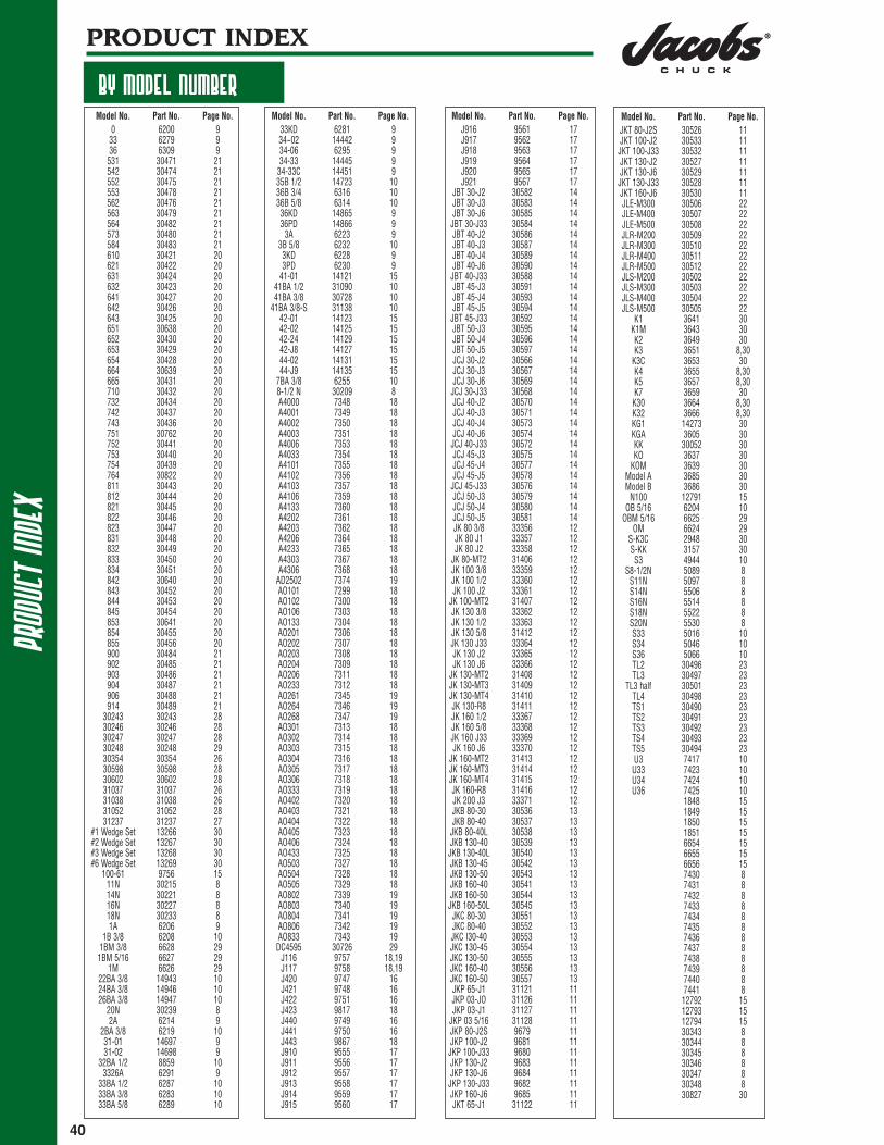
PRODUCT INDEX
BY MODEL NUMBERModel No. Part No. Page No.
0 6200 933 6279 936 6309 9
531 30471 21542 30474 21552 30475 21553 30478 21562 30476 21563 30479 21564 30482 21573 30480 21584 30483 21610 30421 20621 30422 20631 30424 20632 30423 20641 30427 20642 30426 20643 30425 20651 30638 20652 30430 20653 30429 20654 30428 20664 30639 20665 30431 20710 30432 20732 30434 20742 30437 20743 30436 20751 30762 20752 30441 20753 30440 20754 30439 20764 30822 20811 30443 20812 30444 20821 30445 20822 30446 20823 30447 20831 30448 20832 30449 20833 30450 20834 30451 20842 30640 20843 30452 20844 30453 20845 30454 20853 30641 20854 30455 20855 30456 20900 30484 21902 30485 21903 30486 21904 30487 21906 30488 21914 30489 21
30243 30243 2830246 30246 2830247 30247 2830248 30248 2930354 30354 2630598 30598 2830602 30602 2831037 31037 2631038 31038 2631052 31052 2831237 31237 27
#1 Wedge Set 13266 30#2 Wedge Set 13267 30#3 Wedge Set 13268 30#6 Wedge Set 13269 30
100-61 9756 1511N 30215 814N 30221 816N 30227 818N 30233 81A 6206 9
1B 3/8 6208 101BM 3/8 6628 29
1BM 5/16 6627 291M 6626 29
22BA 3/8 14943 1024BA 3/8 14946 1026BA 3/8 14947 10
20N 30239 82A 6214 9
2BA 3/8 6219 1031-01 14697 931-02 14698 9
32BA 1/2 8859 103326A 6291 9
33BA 1/2 6287 1033BA 3/8 6283 1033BA 5/8 6289 10
Model No. Part No. Page No.33KD 6281 934~02 14442 934-06 6295 934-33 14445 9
34-33C 14451 935B 1/2 14723 1036B 3/4 6316 1036B 5/8 6314 1036KD 14865 936PD 14866 9
3A 6223 93B 5/8 6232 103KD 6228 93PD 6230 9
41-01 14121 1541BA 1/2 31090 1041BA 3/8 30728 10
41BA 3/8-S 31138 1042-01 14123 1542-02 14125 1542-24 14129 1542-J8 14127 1544-02 14131 1544-J9 14135 15
7BA 3/8 6255 108-1/2 N 30209 8A4000 7348 18A4001 7349 18A4002 7350 18A4003 7351 18A4006 7353 18A4033 7354 18A4101 7355 18A4102 7356 18A4103 7357 18A4106 7359 18A4133 7360 18A4202 7361 18A4203 7362 18A4206 7364 18A4233 7365 18A4303 7367 18A4306 7368 18
AD2502 7374 19AO101 7299 18AO102 7300 18AO106 7303 18AO133 7304 18AO201 7306 18AO202 7307 18AO203 7308 18AO204 7309 18AO206 7311 18AO233 7312 18AO261 7345 19AO264 7346 19AO268 7347 19AO301 7313 18AO302 7314 18AO303 7315 18AO304 7316 18AO305 7317 18AO306 7318 18AO333 7319 18AO402 7320 18AO403 7321 18AO404 7322 18AO405 7323 18AO406 7324 18AO433 7325 18AO503 7327 18AO504 7328 18AO505 7329 18AO802 7339 19AO803 7340 19AO804 7341 19AO806 7342 19AO833 7343 19DC4595 30726 29
J116 9757 18,19J117 9758 18,19J420 9747 16J421 9748 16J422 9751 16J423 9817 18J440 9749 16J441 9750 16J443 9867 18J910 9555 17J911 9556 17J912 9557 17J913 9558 17J914 9559 17J915 9560 17
Model No. Part No. Page No.J916 9561 17J917 9562 17J918 9563 17J919 9564 17J920 9565 17J921 9567 17
JBT 30-J2 30582 14JBT 30-J3 30583 14JBT 30-J6 30585 14JBT 30-J33 30584 14JBT 40-J2 30586 14JBT 40-J3 30587 14JBT 40-J4 30589 14JBT 40-J6 30590 14JBT 40-J33 30588 14JBT 45-J3 30591 14JBT 45-J4 30593 14JBT 45-J5 30594 14
JBT 45-J33 30592 14JBT 50-J3 30595 14JBT 50-J4 30596 14JBT 50-J5 30597 14JCJ 30-J2 30566 14JCJ 30-J3 30567 14JCJ 30-J6 30569 14JCJ 30-J33 30568 14JCJ 40-J2 30570 14JCJ 40-J3 30571 14JCJ 40-J4 30573 14JCJ 40-J6 30574 14JCJ 40-J33 30572 14JCJ 45-J3 30575 14JCJ 45-J4 30577 14JCJ 45-J5 30578 14JCJ 45-J33 30576 14JCJ 50-J3 30579 14JCJ 50-J4 30580 14JCJ 50-J5 30581 14JK 80 3/8 33356 12JK 80 J1 33357 12JK 80 J2 33358 12
JK 80-MT2 31406 12JK 100 3/8 33359 12JK 100 1/2 33360 12JK 100 J2 33361 12
JK 100-MT2 31407 12JK 130 3/8 33362 12JK 130 1/2 33363 12JK 130 5/8 31412 12JK 130 J33 33364 12JK 130 J2 33365 12JK 130 J6 33366 12
JK 130-MT2 31408 12JK 130-MT3 31409 12JK 130-MT4 31410 12JK 130-R8 31411 12JK 160 1/2 33367 12JK 160 5/8 33368 12JK 160 J33 33369 12JK 160 J6 33370 12
JK 160-MT2 31413 12JK 160-MT3 31414 12JK 160-MT4 31415 12JK 160-R8 31416 12JK 200 J3 33371 12JKB 80-30 30536 13JKB 80-40 30537 13
JKB 80-40L 30538 13JKB 130-40 30539 13
JKB 130-40L 30540 13JKB 130-45 30542 13JKB 130-50 30543 13JKB 160-40 30541 13JKB 160-50 30544 13
JKB 160-50L 30545 13JKC 80-30 30551 13JKC 80-40 30552 13JKC I30-40 30553 13JKC 130-45 30554 13JKC 130-50 30555 13JKC 160-40 30556 13JKC 160-50 30557 13JKP 65-J1 31121 11JKP 03-JO 31126 11JKP 03-J1 31127 11
JKP 03 5/16 31128 11JKP 80-J2S 9679 11JKP 100-J2 9681 11
JKP 100-J33 9680 11JKP 130-J2 9683 11JKP 130-J6 9684 11
JKP 130-J33 9682 11JKP 160-J6 9685 11JKT 65-J1 31122 11
Model No. Part No. Page No.JKT 80-J2S 30526 11JKT 100-J2 30533 11
JKT 100-J33 30532 11JKT 130-J2 30527 11JKT 130-J6 30529 11
JKT 130-J33 30528 11JKT 160-J6 30530 11JLE-M300 30506 22JLE-M400 30507 22JLE-M500 30508 22JLR-M200 30509 22JLR-M300 30510 22JLR-M400 30511 22JLR-M500 30512 22JLS-M200 30502 22JLS-M300 30503 22JLS-M400 30504 22JLS-M500 30505 22
K1 3641 30K1M 3643 30K2 3649 30K3 3651 8,30
K3C 3653 30K4 3655 8,30K5 3657 8,30K7 3659 30K30 3664 8,30K32 3666 8,30KG1 14273 30KGA 3605 30KK 30052 30KO 3637 30
KOM 3639 30Model A 3685 30Model B 3686 30
N100 12791 15OB 5/16 6204 10
OBM 5/16 6625 29OM 6624 29
S-K3C 2948 30S-KK 3157 30S3 4944 10
S8-1/2N 5089 8S11N 5097 8S14N 5506 8S16N 5514 8S18N 5522 8S20N 5530 8S33 5016 10S34 5046 10S36 5066 10TL2 30496 23TL3 30497 23
TL3 half 30501 23TL4 30498 23TS1 30490 23TS2 30491 23TS3 30492 23TS4 30493 23TS5 30494 23U3 7417 10U33 7423 10U34 7424 10U36 7425 10
1848 151849 151850 151851 156654 156655 156656 157430 87431 87432 87433 87434 87435 87436 87437 87438 87439 87440 87441 812792 1512793 1512794 1530343 830344 830345 830346 830347 830348 830827 30

PRODUCT INDEXPRODUCT
INDEX
BY PART NUMBER
41
Part No. Model No. Page No.1848 151849 151850 151851 152948 S-K3C 303157 S-KK 283605 KGA 283637 KO 283639 KOM 283641 K1 283643 K1M 283649 K2 283651 K3 8,283653 K3C 283655 K4 8,283657 K5 8,283659 K7 283664 K30 8,283666 K32 8,283685 Model A 283686 Model B 283687 Model C 284944 S3 105016 S33 105046 S34 105066 S36 105089 S8-1/2N 85097 S11N 85506 S14N 85514 S16N 85522 S18N 85530 S20N 86200 0 96204 OB 5/16 106206 1A 96208 1B 3/8 106214 2A 96219 2BA 3/8 106223 3A 96228 3KD 96230 3PD 96232 3B 5/8 106255 7BA 3/8 106279 33 96281 33KD 96283 33BA 3/8 106287 33BA 1/2 106289 33BA 5/8 106291 3326A 96295 34-06 96309 36 96314 36B 5/8 106316 36B 3/4 106624 OM 276625 OBM 5/16 276626 1M 276627 1BM 5/16 276628 1BM 3/8 276654 146655 146656 147299 AO101 177300 AO102 177303 AO106 177304 AO133 177306 AO201 177307 AO202 177308 AO203 177309 AO204 177311 AO206 177312 AO233 177313 AO301 177314 AO302 177315 AO303 177316 AO304 177317 AO305 177318 AO306 177319 AO333 177320 AO402 177321 AO403 177322 AO404 177323 AO405 177324 AO406 177325 AO433 177327 AO503 177328 AO504 177329 AO505 177339 AO802 187340 AO803 187341 AO804 187342 AO806 187343 AO833 187345 AO261 187346 AO264 18
Part No. Model No. Page No.7347 AO268 187348 A4000 177349 A4001 177350 A4002 177351 A4003 177353 A4006 177354 A4033 177355 A4101 177356 A4102 177357 A4103 177359 A4106 177360 A4133 177361 A4202 177362 A4203 177364 A4206 177365 A4233 177367 A4303 177368 A4306 177374 AD2502 187417 U3 107423 U33 107424 U34 107425 U36 107430 87431 87432 87433 87434 87435 87436 87437 87438 87439 87440 87441 88859 32BA 1/2 109555 J910 169556 J911 169557 J912 169558 J913 169559 J914 169560 J915 169561 J916 169562 J917 169563 J918 169564 J919 169565 J920 169567 J921 169679 JKP 80-J2S 119680 JKP 100-J33 119681 JKP 100-J2 119682 JKP 130-J33 119683 JKP 130-J2 119684 JKP 130-J6 119685 JKP 160-J6 119747 J420 159748 J421 159749 J440 159750 J441 159751 J422 159756 100-61 149757 J116 17,189758 J117 17,189817 J423 179867 J443 1712791 N100 1412792 1412793 1412794 1413266 #1 Wedge Set 2813267 #2 Wedge Set 2813268 #3 Wedge Set 2813269 #6 Wedge Set 2814121 41-01 1414123 42-01 1414125 42-02 1414127 42-J8 1414129 42-24 1414131 44-02 1414135 44-J9 1414273 KG1 2814442 34~02 914445 34-33 914451 34-33C 914697 31-01 914698 31-02 914723 35B 1/2 10 14865 36KD 914866 36PD 914943 22BA 3/8 1014946 24BA 3/8 1014947 26BA 3/8 1030052 KK 2830209 8-1/2 N 8
Part No. Model No. Page No.30215 11N 830221 14N 830227 16N 830233 18N 830239 20N 830243 30243 2630246 30246 2630247 30247 2630248 30248 2730343 830344 830345 830346 830347 830348 830354 30354 2430421 610 1930422 621 1930423 632 1930424 631 1930425 643 1930426 642 1930427 641 1930428 654 1930429 653 1930430 652 1930431 665 1930432 710 1930434 732 1930436 743 1930437 742 1930439 754 1930440 753 1930441 752 1930443 811 1930444 812 1930445 821 1930446 822 1930447 823 1930448 831 1930449 832 1930450 833 1930451 834 1930452 843 1930453 844 1930454 845 1930455 854 1930456 855 1930471 531 2030474 542 2030475 552 2030476 562 2030478 553 2030479 563 2030480 573 2030482 564 2030483 584 2030484 900 2030485 902 2030486 903 2030487 904 2030488 906 2030489 914 2030490 TS1 2230491 TS2 2230492 TS3 2230493 TS4 2230494 TS5 2230496 TL2 2230497 TL3 2230498 TL4 2230501 TL3 half 2230502 JLS-M200 2130503 JLS-M300 2130504 JLS-M400 2130505 JLS-M500 2130506 JLE-M300 2130507 JLE-M400 2130508 JLE-M500 2130509 JLR-M200 2130510 JLR-M300 2130511 JLR-M400 2130512 JLR-M500 2130526 JKT 80-J2S 1130527 JKT 130-J2 1130528 JKT 130-J33 1130529 JKT 130-J6 1130530 JKT 160-J6 1130532 JKT 100-J2 1130533 JKT 100-J33 1130536 JKB 80-30 1230537 JKB 80-40 1230538 JKB 80-40L 1230539 JKB 130-40 12
Part No. Model No. Page No.30540 JKB 130-40L 1230541 JKB 160-40 1230542 JKB 130-45 1230543 JKB 130-50 1230544 JKB 160-50 1230545 JKB 160-50L 1230551 JKC 80-30 1230552 JKC 80-40 1230553 JKC I30-40 1230554 JKC 130-45 1230555 JKC 130-50 1230556 JKC 160-40 1230557 JKC 160-50 1230566 JCJ 30-J2 1330567 JCJ 30-J3 1330568 JCJ 30-J33 1330569 JCJ 30-J6 1330570 JCJ 40-J2 1330571 JCJ 40-J3 1330572 JCJ 40-J33 1330573 JCJ 40-J4 1330574 JCJ 40-J6 1330575 JCJ 45-J3 1330576 JCJ 45-J33 1330577 JCJ 45-J4 1330578 JCJ 45-J5 1330579 JCJ 50-J3 1330580 JCJ 50-J4 1330581 JCJ 50-J5 1330582 JBT 30-J2 1330583 JBT 30-J3 1330584 JBT 30-J33 1330585 JBT 30-J6 1330586 JBT 40-J2 1330587 JBT 40-J3 1330588 JBT 40-J33 1330589 JBT 40-J4 1330590 JBT 40-J6 1330591 JBT 45-J3 1330592 JBT 45-J33 1330593 JBT 45-J4 1330594 JBT 45-J5 1330595 JBT 50-J3 1330596 JBT 50-J4 1330597 JBT 50-J5 1330598 30598 2630602 30602 2630638 651 1930639 664 1930640 842 1930641 853 1930726 DC4595 2730728 41BA 3/8 1030762 751 1930822 764 1930827 2831037 31037 2431038 31038 2431052 31052 2631090 41BA 1/2 1031121 JKP 65-J1 1131122 JKT 65-J1 1131126 JKP 03-J0 1131127 JKP 03-J1 1131128 JKP 03 5/16 1131138 41BA 3/8-S 1031237 31237 2531406 JK 80-MT2 1231407 JK 100-MT2 1231408 JK 130-MT2 1231409 JK 130-MT3 1231410 JK 130-MT4 1231411 JK 130-R8 1231412 JK 130 5/8 1231413 JK 160-MT2 1231414 JK 160-MT3 1231415 JK 160-MT4 1231416 JK 160-R8 1233356 JK 80 3/8 1233357 JK 80 J1 1233358 JK 80 J2 1233359 JK 100 3/8 1233360 JK 100 1/2 1233361 JK 100 J2 1233362 JK 130 3/8 1233363 JK 130 1/2 1233364 JK 130 J33 1233365 JK 130 J2 1233366 JK 130 J6 1233367 JK 160 1/2 1233368 JK 160 5/8 1233369 JK 160 J33 1233370 JK 160 J6 1233371 JK 200 J3 12

deci
mal
equi
vale
ntch
art
42
DECIMAL EQUIVALENT CHART
Drill DecimalSize Inches0.30mm 0.01180.32mm 0.012680 0.01350.35mm 0.013879 0.01450.38mm 0.01501/64 0.01560.40mm 0.015778 0.01600.42mm 0.01650.45mm 0.017777 0.01800.48mm 0.01890.50mm 0.019776 0.020075 0.02100.55mm 0.021174 0.02250.60mm 0.023673 0.02400.62mm 0.024472 0.02500.65mm 0.025671 0.02600.70mm 0.027670 0.028069 0.02920.75mm 0.029568 0.03101/32 0.03120.80mm 0.031567 0.032066 0.03300.85mm 0.033565 0.03500.90mm 0.035464 0.036063 0.03700.95mm 0.037462 0.038061 0.03901.00mm 0.039460 0.040059 0.04101.05mm 0.041358 0.042057 0.04301.10mm 0.04331.15mm 0.045356 0.04653/64 0.04691.20mm 0.04721.25mm 0.04921.30mm 0.051255 0.05201.35mm 0.0531
Drill DecimalSize Inches54 0.05501.40mm 0.05511.45mm 0.05711.50mm 0.059153 0.05951.55mm 0.06101/16 0.06251.60mm 0.063052 0.06351.65mm 0.06501.70mm 0.066951 0.06701.75mm 0.068950 0.07001.80mm 0.07091.85mm 0.072849 0.07301.90mm 0.074848 0.07601.95mm 0.07685/64 0.078147 0.07852.00mm 0.07872.05mm 0.080746 0.081045 0.08202.10mm 0.08272.15mm 0.084644 0.08602.20mm 0.08662.25mm 0.088643 0.08902.30mm 0.09062.35mm 0.092542 0.09353/32 0.09382.40mm 0.094541 0.09602.45mm 0.096540 0.09802.50mm 0.098439 0.099538 0.10152.60mm 0.102437 0.10402.70mm 0.106336 0.10657/64 0.109435 0.11002.80mm 0.110234 0.111033 0.11302.90mm 0.114232 0.11603.00mm 0.118131 0.1200
Drill DecimalSize Inches3.10mm 0.12201/8 0.12503.20mm 0.126030 0.12853.30mm 0.12993.40mm 0.133929 0.13603.50mm 0.137828 0.14059/64 0.14063.60mm 0.141127 0.14403.70mm 0.145726 0.141725 0.14953.80mm 0.149624 0.15203.90mm 0.153523 0.15405/32 0.156222 0.15704.00mm 0.157521 0.159020 0.16104.10mm 0.16144.20mm 0.165419 0.16604.30mm 0.169318 0.169511/64 0.171917 0.17304.40mm 0.173216 0.17704.50mm 0.177215 0.18004.60mm 0.181114 0.18204.70 13 0.18503/16 0.18754.80 12 0.189011 0.19104.90mm 0.192910 0.19359 0.19605.00mm 0.19698 0.19905.10mm 0.20087 0.201013/64 0.20316 0.2045.20mm 0.20475 0.20555.30mm 0.20874 0.20905.40mm 0.21263 0.2130
Drill DecimalSize Inches5.50mm 0.21657/32 0.21885.60mm 0.22052 0.22105.70mm 0.22441 0.22805.80mm 0.22835.90mm 0.2323A 0.234015/64 0.23446.00mm 0.2362B 0.23806.10mm 0.2402C 0.24206.20mm 0.2441D 0.24606.30mm 0.24801/4, E 0.25006.40mm 0.25206.50mm 0.2559F 0.25706.60mm 0.2598G 0.26106.70mm 0.263817/64 0.2656H 0.26606.80mm 0.26776.90mm 0.2717I 0.27207.00mm 0.2756J 0.27707.10mm 0.2795K 0.28109/32 0.28127.20mm 0.28357.30mm 0.2874L 0.29007.40mm 0.2913M 0.29507.50mm 0.295319/64 0.29697.60mm 0.2992N 0.30207.70mm 0.30317.80mm 0.30717.90mm 0.31105/16 0.31258.00mm 0.3150O 0.31608.10mm 0.31898.20mm 0.3228P 0.32308.30mm 0.326821/64 0.32818.40mm 0.3307Q 0.3320
Drill DecimalSize Inches8.50mm 0.33468.60mm 0.3386R 0.33908.70mm 0.342511/32 0.34388.80mm 0.3465S 0.34808.90mm 0.35049.00mm 0.3543T 0.35809.10mm 0.358323/64 0.35949.20mm 0.36229.30mm 0.3661U 0.36809.40mm 0.37019.50mm 0.37403/8 0.3750V 0.37709.60mm 0.37809.70mm 0.38199.80mm 0.3858W 0.38609.90mm 0.389825/64 0.390610.00mm 0.3937X 0.397010.20mm 0.4016Y 0.404013/32 0.4062Z 0.413010.50mm 0.413427/64 0.421910.80mm 0.425211.00mm 0.43317/16 0.437511.20mm 0.440911.50mm 0.452829/64 0.453111.80mm 0.464615/32 0.468812.00mm 0.472412.20mm 0.480331/64 0.484412.50mm 0.49211/2 0.500012.80mm 0.503913.00mm 0.511833/64 0.515613.20mm 0.519717/32 0.531213.50mm 0.531513.80mm 0.543336/64 0.546914.00mm 0.551214.25mm 0.5610
Drill DecimalSize Inches9/16 0.562514.50mm 0.570937/64 0.578114.75mm 0.580715.00mm 0.590619/32 0.593815.25mm 0.600439/64 0.609415.50mm 0.610215.75mm 0.62015/8 0.625016.00mm 0.629916.25mm 0.639841/64 0.640616.50mm 0.649621/32 0.656216.75mm 0.659417.00mm 0.669343/64 0.671917.25mm 0.679111/16 0.687517.50mm 0.689045/64 0.703118.00mm 0.708723/32 0.718818.50mm 0.728347/84 0.734419.00mm 0.74803/4 0.750049/64 0.765619.50mm 0.767725/32 0.781220.00mm 0.787451/64 0.796920.50mm 0.807113/16 0.812521.00mm 0.826853/64 0.828127/32 0.843821.50mm 0.846555/64 0.859422.00mm 0.86617/8 0.875022.50mm 0.885857/64 0.890623.00mm 0.905529/32 0.906259/64 0.921923.50mm 0.925215/16 0.937524.00mm 0.944961/64 0.953124.50mm 0.964631/32 0.968825.00mm 0.984363/64 0.98441” 1.0000

WARRANTY INFORMATION
Jacobs® chucks, chuck keys, toolholders, work holders and accessories, manufactured or distrib-uted by The Jacobs® Chuck Manufacturing Company and the Danaher Tool Group, are warranted tobe free from defects in materials or workmanship for one year from the date of purchase.
This warranty applies only to the first person who buys the products directly from a Jacobs® prod-ucts distributor representative. The Jacobs® Chuck Manufacturing Company and the Danaher ToolGroup cannot be responsible for products which have been abused, misused, or modified. Thiswarranty does not apply to any parts, components or accessories not manufactured by The Jacobs®
Chuck Manufacturing Company and the Danaher Tool Group.
If a Jacobs® product proves defective within one year after purchase, simply return it to the placefrom which it was purchased or to the nearest distributor of Jacobs® products, transportationcharges prepaid. Enclose your name and address, a short description of the defect and proof of thedate of purchase. At its option, The Jacobs® Chuck Manufacturing Company andthe Danaher Tool Group will replace the product free of charge or refund the full purchase price ifthey find the product to be defective. The sole liability of The Jacobs® Chuck ManufacturingCompany and the Danaher Tool Group and your exclusive remedy under this Warranty is limited torepair or replacement of the defective product or to a full refund of its purchase price.
All replacement parts sales and new repair service for Jacobs® High Precision Keyless Chucks are available through our authorized service center: Angle Repair Service, Inc.
175 Angle DriveBeckley, WV 25801(304) 253-5279
There are no other warranties, express or implied, including those of merchantability or fitness for aparticular purpose, beyond those described above. In no event shall the liability of The Jacobs® ChuckManufacturing Company and the Danaher Tool Group exceed the purchase price of the products, norshall The Jacobs® Chuck Manufacturing Company and the Danaher Tool Group be liable for incidental,consequential, or special damages, costs or expenses, excepting only the cost or expense of repair,replacement or refund as described above.
PLEASE NOTE:Without notice, The Jacobs Chuck Manufacturing Company® and the Danaher Tool Group reservethe right to change the design, material composition and dimensional specifications for all productsoffered in this catalog.
43

Danaher Tool GroupP.O. Box 11011 McCormick RoadSuite 150Hunt Valley, MD 21031
Phone: 800-866-5753Fax: 800-234-0472
Catalog Number: 89074-54Rev. 5/05Printed in U.S.A.