Industrial Product Design by Using Two-Dimensional...
131
Industrial Product Design by Using Two-Dimensional Material in the Context of Origamic Structure and Integrity By Nergiz YİĞİT A Dissertation Submitted to the Graduate School in Partial Fulfillment of the Requirements for the Degree of MASTER OF INDUSTRIAL DESIGN Department: Industrial Design Major: Industrial Design İzmir Institute of Technology İzmir, Turkey July, 2004
Transcript of Industrial Product Design by Using Two-Dimensional...

Industrial Product Design by Using Two-Dimensional Material in the Context of Origamic Structure
and Integrity
By
Nergiz YİĞİT
A Dissertation Submitted to the Graduate School in Partial Fulfillment of the
Requirements for the Degree of
MASTER OF INDUSTRIAL DESIGN
Department: Industrial Design
Major: Industrial Design
İzmir Institute of Technology İzmir, Turkey
July, 2004

We approve the thesis of Nergiz YİĞİT
Date of Signature .................................................. 28.07.2004
Assist. Prof. Yavuz SEÇKİN
Supervisor
Department of Industrial Design
.................................................. 28.07.2004
Assist.Prof. Dr. Önder ERKARSLAN
Department of Industrial Design
.................................................. 28.07.2004
Assist. Prof. Dr. A. Can ÖZCAN
İzmir University of Economics, Department of Industrial Design
.................................................. 28.07.2004
Assist. Prof. Yavuz SEÇKİN
Head of Department

ACKNOWLEDGEMENTS
I would like to thank my advisor Assist. Prof. Yavuz Seçkin for his continual
advice, supervision and understanding in the research and writing of this thesis.
I would also like to thank Assist. Prof. Dr. A. Can Özcan, and Assist.Prof. Dr.
Önder Erkarslan for their advices and supports throughout my master’s studies.
I am grateful to my friends Aslı Çetin and Deniz Deniz for their invaluable
friendships, and I would like to thank to Yankı Göktepe for his being.
I would also like to thank my family for their patience, encouragement, care, and
endless support during my whole life.
ABSTRACT
Throughout the history of industrial product design, there have always been
attempts to shape everyday objects from a single piece of semi-finished industrial
materials such as plywood, sheet metal, plastic sheet and paper-based sheet. One of the
ways to form these two-dimensional materials into three-dimensional products is
bending following cutting. Similar concepts of this spatial transformation are
encountered in the origami form, which has a planar surface in unfolded state, then
transforms to a three-dimensional state by folding or by folding following cutting. If so,
conceptually it may be useful to think of one-axis bending, which is a manufacturing
technique, is somewhat similar to folding paper.
In this regard, the studies in the scope of computational origami, which light the
way for real-world problems such as how sheets of material will behave under stress,
have applications especially in ‘manufacturing phase’ of industrial product design.
Besides manufacturing phase, origami design is also used as a product design tool either
in ‘concept creating phase’ (in the context of its concepts) or in ‘form creating phase’
(in the context of its design principles).
In this thesis, the designing of industrial products, which are made from sheet
material, is presented in a framework that considers the origami design. In the
theoretical framework, evolutionary progression of origami design is discussed briefly
in order to comprehend the situation of origami design in distinct application fields.
Moreover, the elements, principles, basics of origami design and origamic structures are
generally introduced. The theoretical framework is completed with the descriptions of
the concepts on origami design and origamic structures. In the practical framework,
typical applications that have origamic structures in distinct industrial product fields are
exemplified. Furthermore, sheet materials and their bending process are taken up
separately. By means of its excessive advantages, sheet metal bending is particularly
emphasized. The practical framework is completed with several case studies base on
sheet metal bending. Finally, the study is concluded with the evaluation of the origamic-
structured product in respect of good design principles. Furthermore, designing by
considering origami design is recommended to designer to design a good industrial
product.
iv

ÖZ
Tasarım tarihi boyunca, gündelik objeleri tek bir parça kontraplak, metal levha,
plastik levha ve kağıt esaslı levha gibi yarı ürünlerden biçimlendirme girişiminde
bulunulmuştur. İki boyutlu bu levha malzemeleri üç boyutlu ürünlere dönüştürme
yöntemlerinden birisi, kesmeyi takiben bükmedir. Buna benzer bir uzamsal dönüşüme,
açılmış bir durumdayken düzlemsel bir yüzeyi olan, daha sonra katlayarak ya da
kesmeyi takiben katlayarak üç boyutlu bir hale dönüştürülen origami yapılarında
rastlanır. Öyleyse, bir imalat tekniği olan tek eksenli bükmenin kağıt katlamaya
benzediğini düşünmek kavramsal olarak yararlı olabilir.
Bu bakış açısıyla, matematiksel origami kapsamında yer alan ve levha
malzemelerin belli bir baskı altındaki davranışlarına açıklık getiren çalışmalar özellikle
endüstri ürünleri tasarımının ‘imalat safhası’nda uygulama alanı bulumaktadır. Origami
tasarımı, imalat safhasının yanısıra, hem ‘konsept tasarımı safhası’nda (tasarım
konseptleri bağlamında) hem de ‘form tasarımı safhası’nda (tasarım prensipleri
bağlamında) bir tasarım aracı olarak da kullanılır.
Dolayısıyla, bu tezde, levha malzemelerden yapılmış endüstri ürünlerinin
tasarımı, origami tasarımını göz önüne alan bir çerçevede sunulmuştur. Teorik
çerçevede, origami tasarımının farklı uygulama alanlarındaki konumunu kavrayabilmek
için evrimsel gelişimine kısaca değinilmiştir. Ayrıca, origami tasarımının elemanları,
prensipleri, esasları ve origami türündeki yapılar tanıtılmıştır. Teorik çerçeve, origami
türündeki yapılara ve origami tasarımına dair kavramların betimlenmesiyle
tamamlanmıştır. Pratik çerçevede, origami türü yapılara sahip tipik ürün uygulamaları
farklı alanlara dair olmak üzere örneklenmiştir. Bunun yanında, levha malzemeler ve
bükülme yöntemleri ayrı ayrı ele alınmıştır. Çok sayıda avantajı olduğu için, metal
levhaların bükülmesi üzerinde özellikle durulmuştur. Pratik çerçeve, metal levhaların
bükülmesine dayalı birkaç uygulama ile tamamlanmıştır. Çalışmanın sonunda, origamik
yapıya sahip endüstri ürünleri ‘iyi tasarım prensipleri’ne göre değerlendirilmiş, daha da
fazlası, iyi bir ürün tasarlayabilmeleri için, tasarımcıya origami tasarımını göz önünde
alarak tasarım yapabileceği salık verilmiştir.
v

TABLE OF CONTENTS
LIST OF FIGURES ......................................................................................................... ix
Chapter 1. INTRODUCTION........................................................................................ 1
1.1. Definition of the Problem .............................................................................. 1
1.2. Aims of the Study .......................................................................................... 1
1.3. Method of the Study ...................................................................................... 2
Chapter 2. NATURE OF ORIGAMI DESIGN AND ORIGAMIC STRUCTURE ...... 4
2.1. Overview on Origami .................................................................................... 4
2.1.1. The Origins of the Term ‘Origami’ ................................................ 4
2.1.2. Evolution of Origami and Origami Design..................................... 5
2.1.3. Definition of Origami Design ....................................................... 12
2.2. Elements of Origami Design........................................................................ 13
2.3. Principles of Origami Design ...................................................................... 16
2.4. Basics of Origami Design ............................................................................ 19
2.4.1. Folding and Unfolding.................................................................. 19
2.4.1.1. Folding Geometries........................................................ 21
2.4.1.2. Flat Foldability............................................................... 23
2.4.1.3. Miura Ori Flat Folding Technique................................. 24
2.4.1.4. Wrapping Fold ............................................................... 25
2.4.1.4. Unfolding and Flattening Polyhedra.............................. 25
2.4.2. Base............................................................................................... 26
2.4.3. Crease Pattern ............................................................................... 28
2.4.4. Origami Tessellations ................................................................... 28
2.5. Classification of Origamic Structure ........................................................... 30
2.5.1. Deployable (Transformable) Planar Structures ............................ 31
2.5.1.1. Pop-Up Structures.......................................................... 31
2.5.1.2. Biomimetic Folding Patterns ......................................... 33
2.5.1.3. Deployable Cylinders .................................................... 36
2.5.2. Modular Structures ....................................................................... 37
2.6. Concepts on Origami Design and Origamic Structure ................................ 39
vi
Chapter 3. ORIGAMIC STRUCTURED INDUSTRIAL PRODUCT........................ 42
3.1 Definition of Origamic Structured Industrial Product .................................. 42
3.2. Overview on Origamic Structured Industrial Product ................................. 42
3.2.1. Origamic Structured Sheet Metal Products .................................. 43
3.2.2. Origamic Structured Plywood Products ....................................... 48
3.2.3. Origamic Structured Plastic Sheet Products ................................. 50
3.2.4. Origamic Structured Paper Based Sheet Products ........................ 54
3.3. Forming Two Dimensional Material into Origamic Structured Product ..... 56
3.3.1. Sheet Metal Bending Process ....................................................... 56
3.3.1.1. Designing Sheet Metal................................................... 59
3.3.1.2. Flat Processing (Shearing process) ................................ 62
3.3.1.3. Sheet Metal Bending...................................................... 64
3.3.2. Plywood Bending Process ............................................................ 67
3.3.3. Plastic Sheet Bending Process ...................................................... 70
3.3.4. Paper Sheet Folding Process......................................................... 71
Chapter 4. CASE STUDIES ON ORIGAMIC STRUCTURED PRODUCT ............. 74
4.1. Base.............................................................................................................. 74
4.1.1. Problem Definition ....................................................................... 75
4.1.2. Formal Description of Base .......................................................... 75
4.1.3. Functional Description of Base..................................................... 79
4.2. Pure .............................................................................................................. 81
4.2.1. Problem Definition ....................................................................... 81
4.2.2. Formal Description of Pure........................................................... 81
4.2.3. Functional Description of Pure ..................................................... 85
4.3. Leaf .............................................................................................................. 87
4.3.1. Problem Definition ....................................................................... 87
4.3.2. Formal Description of Leaf........................................................... 87
4.3.3. Functional Description of Leaf ..................................................... 93
4.4. Triori ............................................................................................................ 95
4.4.1. Problem Definition ....................................................................... 95
4.4.2. Formal Description of Triori......................................................... 95
4.4.3. Functional Description of Triori ................................................... 98
4.5. Modulori .................................................................................................... 100
vii
4.5.1. Problem Definition ..................................................................... 100
4.5.2. Formal Description of Modulori................................................. 100
4.5.3. Functional Description of Modulori ........................................... 103
4.6. Windrose.................................................................................................... 105
4.6.1. Problem Definition ..................................................................... 105
4.6.2. Formal Description of Windrose ................................................ 106
4.6.3. Functional Description Of Windrose.......................................... 108
4.7. Radius ........................................................................................................ 109
4.7.1. Problem Definition ..................................................................... 110
4.7.2. Formal Description of Radius..................................................... 110
4.7.3. Functional Description Of Radius .............................................. 110
Chapter 5. CONCLUSION........................................................................................ 112
REFERENCES ............................................................................................................. 115
viii

LIST OF FIGURES
Figure 2.1. The earliest origami models ........................................................................... 5
Figure 2.2. Reference pages to ‘Kirigami’ ....................................................................... 6
Figure 2.3. ‘Tsurifune’ the large folded crane suspended from a chain of small folded
cranes ........................................................................................................... 7
Figure 2.4. Paper cutting and folding examples from Bauhaus Preliminary Course........ 8
Figure 2.5. Curved line folding....................................................................................... 10
Figure 2.6. Crease pattern constituted by Treemaker Program to form a lizard............. 11
Figure 2.7. Crease patterns constituted by Treemaker Program for Kirigami................ 11
Figure 2.8. Tessellation constituted by Tess Program.................................................... 11
Figure 2.9. Crease pattern of a crane. ............................................................................. 15
Figure 2.10. Two most common kinds of symmetry...................................................... 17
Figure 2.11. Samples of rotational symmetries .............................................................. 17
Figure 2.12. The pattern constituted by rotational and reflection symmetries ............... 18
Figure 2.13. Isometries ................................................................................................... 18
Figure 2.14. Seventeen symmetry groups....................................................................... 19
Figure 2.15. Basic Folds ................................................................................................. 20
Figure 2.16. Huzita's six Origami axioms....................................................................... 20
Figure 2.17. Natural folding geometries of square and rectangle................................... 22
Figure 2.18. Geometrically folded structures ................................................................. 23
Figure 2.19. Sample of non-flat foldable form ............................................................... 23
Figure 2.20. A flat-foldable vertex ................................................................................. 24
Figure 2.21. Miura Ori Map Folding .............................................................................. 24
Figure 2.22. Wrapping Fold around a central circular hub............................................. 25
Figure 2.23. Wrapping Fold around a central prismatic hub .......................................... 25
Figure 2.24. Unfolding of an octahedron........................................................................ 26
Figure 2.25. Flattening a tetrahedron, from left to right ................................................. 26
Figure 2.26. Flat foldable Origami bases........................................................................ 27
Figure 2.27. Polyhedral bases of modular origami......................................................... 27
Figure 2.28. Crease pattern ............................................................................................. 28
Figure 2.29. Pre-creasing and twist folding.................................................................... 29
Figure 2.30. Tessellation groups..................................................................................... 29
Figure 2.31. Tessellations designed by Enlai Hooi ........................................................ 30
ix
Figure 2.32. Pop-up structures........................................................................................ 32
Figure 2.33. Additional pop-up effects by folding ......................................................... 33
Figure 2.34. Unfolding manner of hornbeam leaves ...................................................... 34
Figure 2.35. Stages in making `ha-ori' (leaf-folding) ..................................................... 34
Figure 2.36. The leaf-folding structure extends simultaneously in two directions......... 34
Figure 2.37. Leaf patterns. .............................................................................................. 35
Figure 2.38. The deployment of leaf patterns paper model, in four stages .................... 35
Figure 2.39. Deployment of a cylinder ........................................................................... 36
Figure 2.40. Modular patterns......................................................................................... 37
Figure 2.41. Two Fold Star............................................................................................. 38
Figure 2.42. Modular surfaces ........................................................................................ 38
Figure 2.43. Modular structures...................................................................................... 39
Figure 3.1. ‘2D:3D’ Office accessories and racks designed by Charlie Lazor, 1999..... 43
Figure 3.2. Square Dance Low Table, designed by Ronen Kadushin, 2000 .................. 44
Figure 3.3. Piclip, designed by Chris Smith, 2002 ......................................................... 44
Figure 3.4. Prismatic Table, designed by Isamu Noguchi, 1957 .................................... 45
Figure 3.5. Fly, designed by Mehmet Ermiyagil, 2004 .................................................. 45
Figure 3.6. Tufold, By Scot Laughton ............................................................................ 46
Figure 3.7. Origami P1 Table, designed by Mehmet Ermiyagil, 2004........................... 46
Figure 3.8. Noan, designed by Gualtiero Sacchi, 2004 .................................................. 47
Figure 3.9. Diana side table series, Red Dot Award: Product Design 2002, designed by
Konstantin Grcic, 2002, Manufacturer: ClassiCon....................................... 47
Figure 3.10. Plywood Armchair, designed by Gerald Summers, 1934 .......................... 48
Figure 3.11. Capelli Stool, IDEA Industrial Design Excellence Award 2002: designed
by Carol Catalano, 2002 ............................................................................ 49
Figure 3.12. Bend Table, designed by Mehmet Ermiyagil, 2000................................... 49
Figure 3.13. Voxia series, designed by Peter Karpf, 2000 ............................................. 50
Figure 3.14. Fluent, designed by Studio Platform .......................................................... 51
Figure 3.15. Self Lock Kaki, designed by Naoko Takeda, 2000.................................... 51
Figure 3.16. City Knife II, by Kirsten Schambra, 1998, Manufacturer: Nike................ 52
Figure 3.17. Flat Foldable Sandal................................................................................... 53
Figure 3.18. Acrylic series, designed by David Ross, 2001 ........................................... 53
Figure 3.19. Folder Coffeetable , designed by Ole Petter Wullum & Arnstein Sarset... 54
Figure 3.20. Flov Series, designed by Mirzat Koç, 2003 ............................................... 54
x
Figure 3.21. Spotty child's chair, designed by Peter Murdoch, 1963 ............................. 55
Figure 3.22. Sturdy paper pot, designed by Tomoko Fuse ............................................. 55
Figure 3.23. The same pieces despite different functions............................................... 58
Figure 3.24. Sheet Metal forming process...................................................................... 58
Figure 3.25. Saving material by using an optimized placement strategy ....................... 60
Figure 3.26. Rounding outer and inner corners .............................................................. 60
Figure 3.27. Notching the bending zones ....................................................................... 60
Figure 3.28. Bend Radius ............................................................................................... 61
Figure 3.29. Elongated length......................................................................................... 62
Figure 3.30. Resiliency (spring back)............................................................................. 62
Figure 3.31. Various shearing operations ....................................................................... 63
Figure 3.32. Bending process phases.............................................................................. 64
Figure 3.33. Special punch and dies for sheet metal bending......................................... 64
Figure 3.34. V bending styles ......................................................................................... 65
Figure 3.35. Special Bending Operations. ...................................................................... 66
Figure 3.36. Most common forms .................................................................................. 67
Figure 3.37. Cross-layered structure of plywood ........................................................... 67
Figure 3.38. Foiled and laminated plywood ................................................................... 68
Figure 3.39. The EL Plywood Desk was designed by Sheila Kennedy, Developed with
support from the U.S. Department of Energy............................................ 68
Figure 3.40. Plywood bending process........................................................................... 69
Figure 3.41. Hot line bending by manually .................................................................... 70
Figure 3.42. Hot line bending with bending machine..................................................... 71
Figure 3.43. The principle of scoring ............................................................................. 72
Figure 3.44. Working principle of ‘Buckler’ Folding Machine ..................................... 72
Figure 3.45. Working principle of ‘Knife’ Folding Machine ......................................... 72
Figure 4.1. Product Proposal 1: Base.............................................................................. 74
Figure 4.2. One unit form’ Of Base that will be repeated .............................................. 75
Figure 4.3. Constituting the pattern by considering symmetry principal ....................... 76
Figure 4.4. Crease pattern of Base.................................................................................. 76
Figure 4.5. Bending Sequence Of Base .......................................................................... 77
Figure 4.6. Technical Drawings Of Base (measures: mm, scale: 1/20).......................... 78
Figure 4.7. Magazine holder function of Base................................................................ 79
Figure 4.8. Coffee table function of Base ....................................................................... 79
xi

Figure 4.9. Stockability................................................................................................... 79
Figure 4.10. Graphical effect that adds emotional appeal .............................................. 79
Figure 4.11. Perspective Preview 1 of Base ................................................................... 80
Figure 4.12. Perspective Preview 2 of Base ................................................................... 80
Figure 4.13. Product Proposal 2: Pure ............................................................................ 81
Figure 4.14. Unit Forms of Pure ..................................................................................... 82
Figure 4.15. Crease pattern of Pure ................................................................................ 82
Figure 4.16. Bending sequence of Pure .......................................................................... 83
Figure 4.17. Technical drawings of one unit Pure in unfolded state .............................. 83
Figure 4.18. Technical Drawings Of Pure in folded state .............................................. 84
Figure 4.19. Stocking Function....................................................................................... 85
Figure 4.20. Low table function...................................................................................... 85
Figure 4.21. Stockability Of Pure ................................................................................... 85
Figure 4.22. Perspective Preview 1 of Pure.................................................................... 86
Figure 4.23. Perspective Preview 2 of Pure.................................................................... 86
Figure 4.24. Product Proposal 3: Leaf ............................................................................ 87
Figure 4.25. Patterns Constituted By One Leaf Unit ...................................................... 88
Figure 4.26. Crease pattern of one Leaf unit .................................................................. 89
Figure 4.27. Bending Sequence Of One Leaf Unit......................................................... 90
Figure 4.28. Technical Drawings of Patterns Constituted By One Leaf Unit ................ 91
Figure 4.29. Technical Drawings Of one Leaf unit (measures: mm, scale: 1/20) .......... 92
Figure 4.30. Stockability................................................................................................. 93
Figure 4.31. Multipurpose of Leaf unit........................................................................... 93
Figure 4.32. Perspective Previews of Three Leaf Units (first alternative) ..................... 93
Figure 4.33. Perspective Previews of Two Leaf Units (first alternative) ....................... 94
Figure 4.34. Perspective Previews of Two Leaf Units (second alternative)................... 94
Figure 4.35. Perspective Previews of Three Leaf Units (second alternative)................. 94
Figure 4.36. Product Proposal 4: Triori .......................................................................... 95
Figure 4.37. One Unit Form and Three Units Form of TriOri........................................ 96
Figure 4.38. Crease pattern of Triori .............................................................................. 96
Figure 4.39. Technical Drawings Of TriOri (measures: mm, scale: 1/20) ..................... 97
Figure 4.40. Multipurpose of Triori in erected state....................................................... 98
Figure 4.41. Multipurpose of Triori in unerected state................................................... 98
Figure 4.42. Flat packaging of Triori.............................................................................. 98
xii

Figure 4.43. Perspective Preview 1 of TriOri ................................................................. 99
Figure 4.44. Perspective Preview 2 of TriOri ................................................................. 99
Figure 4.45. Product Proposal 5: Modulori .................................................................. 100
Figure 4.46. Crease Pattern Of ModulOri..................................................................... 100
Figure 4.47. Bending sequence of ModulOri ............................................................... 101
Figure 4.48. Technical Drawings of One unit ModulOri in unfolded state.................. 101
Figure 4.49. Technical Drawings Of ModulOri (measures: mm, scale: 1/20) ............. 102
Figure 4.50. Multipurpose of ModulOri ....................................................................... 103
Figure 4.51. Four Units Form Of ModulOri (first alternative)..................................... 103
Figure 4.52. Four Units Form Of ModulOri (second alternative) ................................ 103
Figure 4.53. Two Units Form Of ModulOri (first alternative) ..................................... 104
Figure 4.54. Two Units Form Of ModulOri (second alternative) ................................ 104
Figure 4.55. One Unit Form Of ModulOri ................................................................... 104
Figure 4.56. Perspective Previews of ModulOri........................................................... 105
Figure 4.57. Product Proposal 6: Windrose.................................................................. 105
Figure 4.58. Crease Pattern Of Windrose ..................................................................... 106
Figure 4.59. Bending sequence of Windrose................................................................ 106
Figure 4.60. Technical Drawings of One unit Windrose in unfolded state .................. 106
Figure 4.61. Technical Drawings of Windrose............................................................. 107
Figure 4.62. Multipurposes Of WindRose.................................................................... 108
Figure 4.63. One Unit Form Of WindRose .................................................................. 108
Figure 4.64. Two Units Form Of WindRose ................................................................ 108
Figure 4.65. Four Units Form Of WindRose ................................................................ 108
Figure 4.66. Perspective Previews of WindRose.......................................................... 109
Figure 4.67. Radius Office Systems, Delta Office Systems Design Competition 2003:
Honorable Mention, designed by Nergiz Yiğit, 2003.............................. 109
Figure 4.68. Bending of Radius .................................................................................... 110
Figure 4.69. Technical Drawings of Radius ................................................................. 110
Figure 4.70. Alternative combinations of Radius ......................................................... 111
xiii
CHAPTER 1
INTRODUCTION
1.1 Definition of the Problem
When constituting a pattern to structure a form, nature knows no interruption of
materials and surfaces in order to achieve the economy of materials, methods and
purpose. By imitating these concepts of the nature, in designing, the planar surface are
use to create stable spatial structures and/or dynamic surface movement to achieve the
concept of ‘unity’ and ‘wholeness’ or to integrate the parts, which are formed from
planes, into a seamless whole. Consequently, designing with planar surface have always
been challenging to designers 1920’s onwards. Especially the contemporary designers
of 2000’s are seized by the tendency of constituting a space from continuous surfaces
by bending, curving and folding. Today, it gains popularity designing the products,
which let the separate elements are unified as continuous features. In such a way, a shelf
system and a desk or a seating and its base become a unified whole.
The similar way to form the two-dimensional industrial materials into three-
dimensional products is encountered in the origami design. If so, it is useful to think
considering the origami design techniques, principles, and concepts can assist in the
designing of an industrial product from two-dimensional material.
To comprehend the intellectual properties that are needed for origami design, it
must be clearly discussed in detail, and to understand the product, which is designed by
assisting origami design, and the production techniques of this product are taken up by
exemplifying.
1.2 Aims of the Study
The fundamental aim of the thesis is to clarify how origami design assists to
design an industrial product what the outcome of design by considering origami design
is. By regarding this, it is aimed to define the nature of origami design and origamic
structure in second chapter.
If the form of a product is to some degree the result of how it was manufactured,
it follows that the designer must have a good understanding of all manufacturing
1

processes available, in order to have confidence that the proposed manufacturing
process is the most economical and appropriate. If designers are unaware of certain
available processes, they will be limited in their creative potential. With a good
knowledge base, the designer can propose an array of possible design solutions and
have some confidence that they can be manufactured.
In order to design for high productivity and also to achieve high quality and
controllable material cost, designer should consider the simplification and size reduction
possible in product, and the maximum reduction possible in the number of component
parts. Designer should be aware of the capabilities, particularly of new materials, of
performing multifunctional roles in a product. In this regard, the third chapter is aimed
to have a characteristic, which is an overview of the key manufacturing process related
to two-dimensional materials such as metal sheet, plastic sheet and plywood. However
it is limited with flat processing and bending in order to compromise with the context of
this thesis. Furthermore, in this chapter, it is aimed to clarify how the techniques of
origami design are adapted in manufacturing process and what characteristics of the
origamic-structured products are.
It is aimed in forth chapter, to apply the concept, principles, and techniques of
origami design into a product made from sheet metal by press brake bending.
In the conclusion, it is aimed to evaluate the origamic-structured product.
1.3 Method of the Study
The study is comprised of five chapters. In the first introductory chapter, the
aims and means of the study are defined.
In the second chapter on the nature of the origami design and origamic structure,
origami design is defined and its evolution are mentioned in order to comprehend its
application in distinct design field. Moreover, in order the use it as a design tool in
‘form creating phase’, the elements, principles, and basics of origami design are
discussed in detail. And finally origamic structures are classified.
The third chapter on origamic structured industrial product is constituted from
four main sections. In the first section, the term ‘origamic’ is defined and what the
origamic structured industrial product is determined. In the second section, the concepts
on origami design and origamic structure are taken up in order to use its concepts in
‘concept creating phase’. The comprehensive exemplifying of origamic structured
2
industrial products in distinct product fields constitutes the third section. In the forth
section, the adaptation of the folding techniques to forming processes in manufacturing
phase are discussed separately for sheet metal, plywood and plastic sheet.
The forth chapter consists of several case studies that base on the synthesis of
previous chapters. In such a way that, these case studies are designed by considering
origami design principles, concepts and techniques, and the proposed designs are made
from sheet metal and formed by one-axis bending.
In the conclusion, on the basis of the exemplifying in the third chapter, the
typical characteristics of the origamic-structured products are determined, and then
evaluated by considering good design principles. Consequently, it is recommended to
designer that, it is useful to think of designing by considering origami design makes
way for good design, guide the designer in this way, and usually brings outcomes about
good design.
3

CHAPTER 2
NATURE OF ORIGAMI DESIGN AND ORIGAMIC STRUCTURE
“Folding is an art of seeing something not seen, something not already there”
John Rajchman
2.1 Overview on Origami
In order to comprehend its application in distinct design field, the nature of the
origami design and origamic structures had been defined and its evolution had been
mentioned in this chapter. Moreover, in order the use it as a design tool in ‘form
creating phase’, the elements, principles, and basics of origami design had been
discussed in detail.
2.1.1 The Origins of the Term ‘Origami’
‘Origami’ is a Japanese word, which combines the verb ‘oru’ to fold, and the
noun ‘kami’ paper. Quoting from Merriam Webster’s Third New International
Dictionary, origami means:
1. The art of Japanese paper folding.
2. Something as a representative made by origami.
The term origami was first mentioned during the seventh century A.D in Japan.
It referred to square and rectangular pieces of paper folded into symbolic
representations of the spirit of God, and hung at the shrines as objects of worship.
During the eleventh century A.D. folded paper came to be used for certain special
documents, such as diplomas for Tea Ceremony masters, or masters of swordsmanship;
in such a way that to prevent unauthorized copies from being made. This certificate had
the same meaning as the word ‘diploma’, which also means ‘a letter folded in two’ in
Latin. The term origami referred to the ‘documents’, whereas the term ‘origami tsuki’
referred ‘certified’.
The use of the term origami for recreational paper folding did not appear until
the end of the nineteenth century. Before this time, paper folding was known by a
4
variety of names such as orikata, orisue, orimono, and tatamgami. It is suggested that
the word origami was a direct translation of the German word ‘papierfalten’, brought
into Japan with the Kindergarten Movement (Lister, 1998, p. 2).
2.1.2 Evolution of Origami and Origami Design
Origami is traditionally associated with Japanese culture. However, it is
originated in China with the invention of paper in 105 A.D. The Japanese learned about
paper making in the early seventh century from a Buddhist Monk who came to Japan
from China. In spite of its rapid diffusion, paper remained for years a rare and precious
material, and used for religious ceremonies and important occasion.
Classical Origami
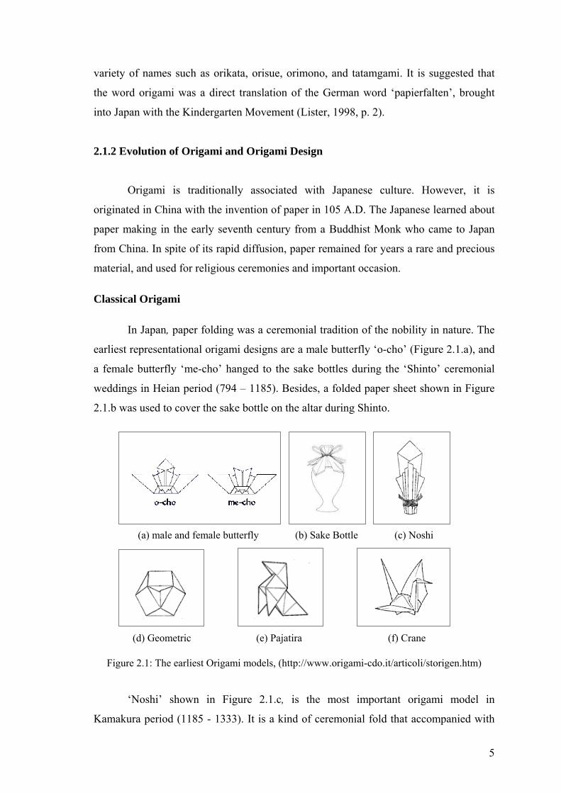
In Japan, paper folding was a ceremonial tradition of the nobility in nature. The
earliest representational origami designs are a male butterfly ‘o-cho’ (Figure 2.1.a), and
a female butterfly ‘me-cho’ hanged to the sake bottles during the ‘Shinto’ ceremonial
weddings in Heian period (794 – 1185). Besides, a folded paper sheet shown in Figure
2.1.b was used to cover the sake bottle on the altar during Shinto.
(a) male and female butterfly (b) Sake Bottle (c) Noshi
(d) Geometric (e) Pajatira (f) Crane
Figure 2.1: The earliest Origami models, (http://www.origami-cdo.it/articoli/storigen.htm)
‘Noshi’ shown in Figure 2.1.c, is the most important origami model in
Kamakura period (1185 - 1333). It is a kind of ceremonial fold that accompanied with
5
valued objects such as swords or gifts presented to others, and entirely distinct from
‘origami-tsuki’ in such a way that it was not certificate, but was attached to gifts to
express good wishes. It differs from other traditional models, so that is obtained by a
simple fold, without any cut. Later on, this tendency shall become predominant in the
so-called pure origami (Honda, 1965, p. 3).
In the eighth century, papermaking and origami was spread out through the Silk
Route to the Near East. Since Muslim religion proscribed the making of representational
figures like human and animal forms, Arab mathematicians and astronomers were
interested in the geometry of tessellation and the folding properties of the square, thus
they explored geometric constructions such as the one shown in Figure 2.1.d
(Crankshaw, 2001, p. 2).
In the twelfth century, the Moors, who are the Muslims of North Africa, brought
paper folding to Spain. The Spanish incorporated the representational forms of nature to
paper folding. The little bird ‘Pajarita’ shown in Figure 2.1.e. is the most known model
of Spanish creation. During the sixteenth and seventeenth centuries, folding table
napkins into elaborate models of animals and ships were the sign of the great nobility in
the palaces of royalty. It is also known that pleated folding of cloth existed in the West
during Egyptian, Greek, Roman and Byzantine periods (Leonardi, 1997).
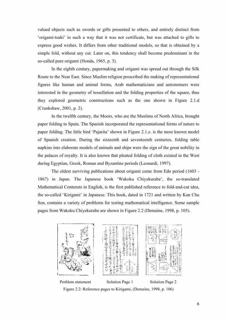
The oldest surviving publications about origami come from Edo period (1603 -
1867) in Japan. The Japanese book ‘Wakoku Chiyekurabe’, the so-translated
Mathematical Contensts in English, is the first published reference to fold-and-cut idea,
the so-called ‘Kirigami’ in Japanese. This book, dated in 1721 and written by Kan Chu
Sen, contains a variety of problems for testing mathematical intelligence. Some sample
pages from Wakoku Chiyekurabe are shown in Figure 2.2 (Demaine, 1998, p. 105).
Problem statement Solution Page 1 Solution Page 2
Figure 2.2: Reference pages to Kirigami, (Demaine, 1998, p. 106)
6
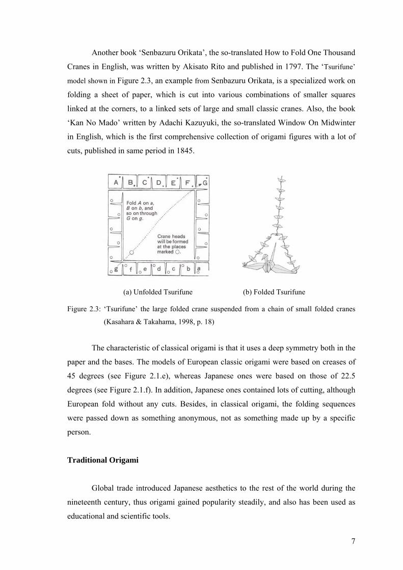
Another book ‘Senbazuru Orikata’, the so-translated How to Fold One Thousand
Cranes in English, was written by Akisato Rito and published in 1797. The ‘Tsurifune’
model shown in Figure 2.3, an example from Senbazuru Orikata, is a specialized work on
folding a sheet of paper, which is cut into various combinations of smaller squares
linked at the corners, to a linked sets of large and small classic cranes. Also, the book
‘Kan No Mado’ written by Adachi Kazuyuki, the so-translated Window On Midwinter
in English, which is the first comprehensive collection of origami figures with a lot of
cuts, published in same period in 1845.
(a) Unfolded Tsurifune (b) Folded Tsurifune
Figure 2.3: ‘Tsurifune’ the large folded crane suspended from a chain of small folded cranes
(Kasahara & Takahama, 1998, p. 18)
The characteristic of classical origami is that it uses a deep symmetry both in the
paper and the bases. The models of European classic origami were based on creases of
45 degrees (see Figure 2.1.e), whereas Japanese ones were based on those of 22.5
degrees (see Figure 2.1.f). In addition, Japanese ones contained lots of cutting, although
European fold without any cuts. Besides, in classical origami, the folding sequences
were passed down as something anonymous, not as something made up by a specific
person.
Traditional Origami
Global trade introduced Japanese aesthetics to the rest of the world during the
nineteenth century, thus origami gained popularity steadily, and also has been used as
educational and scientific tools.
7
The influential educator Friedrich Froebel introduced the paper folding to the
kindergarten movement in Germany around 1835. It was stated in this movement that
the purpose of education was to demonstrate the unity of the universe through a set of
symbolic activities promoting cooperation, the study of nature, and the manual work to
unite brain and hands. Because of paper folding allows students to manipulate
geometric figures physically, and illustrates developing the basic concepts of a point, a
line, and a plane, it has also been used as a tool in mathematic education.
Paper is a fragile substance; but when cut and folded in certain ways it can
become remarkably strong and rigid. Insights gained from experimentation with sheets
of paper, metal and other materials are of obvious relevance to every kind of design
activity. Because of these attributes, paper folding and cutting has been used to teach
important lessons about the nature of construction in design education since 1925. Josef
Albers, a famous designer of Bauhaus Movement who was fascinated by the properties
of materials and their potential when shaped, encouraged the students to manipulate
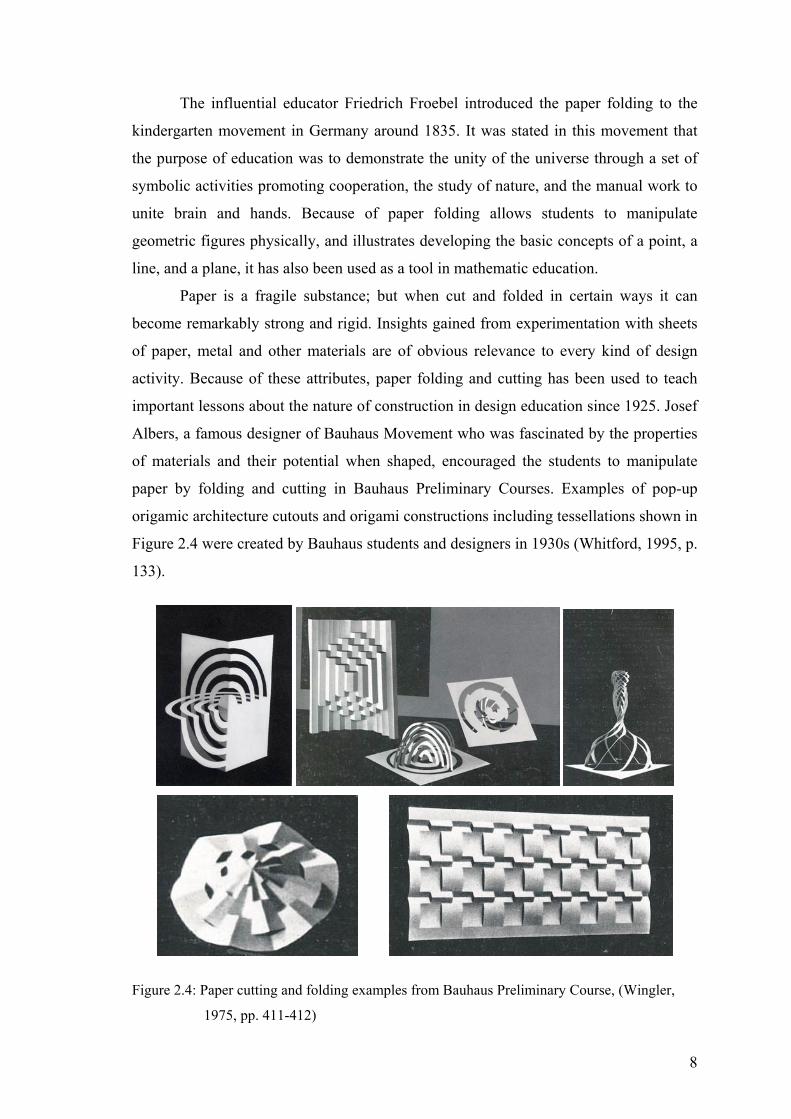
paper by folding and cutting in Bauhaus Preliminary Courses. Examples of pop-up
origamic architecture cutouts and origami constructions including tessellations shown in
Figure 2.4 were created by Bauhaus students and designers in 1930s (Whitford, 1995, p.
133).
Figure 2.4: Paper cutting and folding examples from Bauhaus Preliminary Course, (Wingler,
1975, pp. 411-412)
8

Modern Origami
At second half of the twentieth century, the modern approach to Origami
explored new bases and intensified to geometric folding and the employment of
modules. Besides, the origami books of Japanese, European, and American designers
were published in both Japanese and English. It is stated in these references that the
diagrams, which represent the folding sequence of a model, are important in modern
origami. As they represent the model itself, besides are supposed to show the entire
sequence in order to being reproductive. The idea that particular persons have
intellectual property in folding sequences is also a typical of modern origami.
In 1950s and 1960s, an international origami circle was established by the
creators and folders such as Yoshizawa Akira, Takahama Toshie, Honda Isao, Robert
Harbin, Gershon Legman, Lillian Oppenheimer, Samuel Randlett, and Vicente
Solórzano-Sagredo. National and local organizations, and also many societies, such as
the International Origami Society by Akira Yoshizawa, have been founded. Besides,
Yoshizawa's notation of diagrams was adopted by Harbin and Randlett, and became an
international standard. And also, ‘Origami’ became a universal word in this era.
Recent trend: Computational (mathematical) Origami
Origami has come a long way from cute little birds and decorative objects.
Around 1980s, mathematicians and scientists have begun mapping the laws that
underlie folding, converting words and concepts into algebraic rules. The principles of
computational geometry have been excessively applied to origami design, and also
axioms, which explain how the three-dimensional objects are created from a flat
material by folding, have been formulated.
One of these axioms was the ‘critical pi condition’, discovered by the scientist
Dr. David Huffman. It is explained as, if there is a point or vertex surrounded by four
creases, to fold the form flat, then opposite angles around the vertex must sum to 180
degrees. Afterwards, that condition was reorganized by Kawasaki and generalized for
more than four creases. Today it is known as Kawasaki Theorem, described in section
2.4.1.2, that is the most important theorem on flat fold ability (Wertheim, 2004).
In contrast to classical and traditional origami, where all folds are straight, the
structures based on curved folds have been developed in computational origami by
obeying the rule no cuts or glue. The theme of minimal surface that the form soap
9

bubbles make, was carried into origami by Dr. Huffman, in a way that based on curves
derived from conic sections, such as the hyperbola and the ellipse. Some examples of
curved form, which are folded from a single sheet of paper by Dr. Huffman, are shown
in Figure 2.5.
(a) An origami form of (b) 4 parabolic curved folds (c) A tower-like paper
concentric domes through center structure
Fig 2.5: Curved line folding, (http://www.NYTimes.com, June 22nd, 2004)
Besides the studies on curved lines, studies with straight lines also leaded the
invention of new bases in computational origami. Origami designers Maekawa Jun and
Peter Engel divided the crease patterns into particular triangles and rectangles, and then,
rearranged these atoms to make new crease patterns. By means of these studies, an
advanced algorithm that generates the crease pattern of the base from an arbitrary length
and arrangement of areas, was developed by Meguro Toshiyuki, Kawahata Fumiaki,
and Robert Lang. TreeMaker computer program devised by Robert Lang in 1993
supports the origami design based on this algorithm (Demaine, 2001, p. 20).
TreeMaker is a tool for origami design. Starting from a description of a desired
origami model, TreeMaker computes a crease pattern for folding a base for the model
from an uncut square of paper. It implements the ‘tree method’ for origami design. The
tree method allows designing an origami base in the shape of a specified tree with
desired edge lengths, which can then be folded and shaped into an origami model. It
suggests a method for finding an appropriate mountain-valley assignment for the crease
pattern, and also aims to make optimal use of the paper to create a base for a given
figure with the smallest possible square of paper, or, conversely, to make the largest
possible base from a given square (Cipra, 2001, p. 3).
10

Figure 2.6: Crease pattern constituted by Treemaker to form a lizard, (Lang, 1998, p. 22)
Figure 2.7: Crease patterns constituted by Treemaker for Kirigami, (Demaine, 1998, p. 108)
Tess, developed by a biochemist Alex Bateman, is another computer program
for designing flat-folding origami. This program creates crease patterns for origami
tessellations like shown in Figure 2.8. The user is free to specify the underlying
symmetry group and vary key parameters. In theory, these tessellations are easy to fold
by twisting one part of the paper over another (Cipra, 2001, p. 4).
Figure 2.8: Tessellation constituted by Tess Program (Cipra, 2001, p. 4)
Besides Treemaker and Tess, there has been a constant growing of software
tools to aid the design of origami. 3D Card Maker, developed by Jun Mitani, generates
crease and cut lines for one-piece pop-up structures, and it is capable of creating and
animating the double slit (discussed in section 2.5.1.1). HyperGami, developed by
11
Nishioka and Eisenberg, is software for creating polyhedral models, and also another
program Mathematica is able to simulate folding steps (Lee, 2003, p. 2).
By means of these computer programs and the developments on computational
origami, origami design also drive a force to electronic engineers for folding processors
in order to stock maximum amount of information into the smallest possible area, and
help to biologists about creating properly folded artificial proteins, and also figure out
how to most effectively fold and unfold a roadmap, how to unfold a telescope lens in
outer space without damaging it, and determine the safest way to stow an airbag within
a steering column (Cipra, 2001, p. 2).
Consequently, computational origami, also known as technical folding or
origami sekkei, intends creating flat foldable forms by assistance of computational
geometry, number theory, coding theory and linear algebra.
Computational origami concerns the studies on the structures that are folded to
avoid putting strain on the paper or the relationships of the angles that prevent
stretching and tearing in the case of multiple folds coming into a point, which light the
way for real-world problems such as pressing or bending sheet metal. The studies are
closely relevant to how sheets of other material will behave under stress (Wertheim,
2004).
Thanks to its evolutionary progression, origami design has also been applied to
industrial product design problems mostly in the field of packaging, domestic or office
furniture and accessory. It is a design tool used in either concept-creating phase in the
context of its concepts arise from the nature of origami design, or form-creating phase
by concerning manufacturing processes in the context of its principles and techniques
used to form two-dimensional material into three-dimensional object.
2.1.3 Definition of Origami Design
Origami design is defined as “forming a piece of two-dimensional medium into
a particular form with certain desired properties by folding and cutting” (Demaine,
2001, p. 21). In the point of purist view, this particular form achieved by only straight
line folding of a single color square piece of medium in a deep symmetry; whereas in
the point of non-purist view, cutting and slitting besides straight or curved line folding
is used to form multi-colored mediums (in order to obtain more graphical effect) with
variable outline (in order to obtain certain properties).
12
An origami form is a collection of ‘planes’ in an order. If so, an origami is
represented as a list {planes, order}. A plane is represented as a list {poly, neighbors,
mpoints}, where ‘neighbors’ is a list of neighboring planes; ‘mpoints’ is a list of marked
points determine a line; ‘poly’ is a polygon consisting of vertices that is represented in
two ways: vertex representation and edge representation. An origami is folded along a
line called crease. The crease can be determined by the line, which it passes through
(Takahashi, 2002, p. 3). Consequently, an origami is represented by points, lines and
polygonal planes.
In origami design, a plane is used to create stable spatial structures or dynamic
surface movement that integrate parts into a seamless whole. If so, the unfolded state of
an origami form is two-dimensional, furthermore creating crease pattern and
tessellations involves two-dimensional thinking. In other words, origami design is a
three-dimensional design, which is obtained through two-dimensional design.
Between two-dimensional thinking and three-dimensional thinking, there is a
difference in attitude. Three-dimensional design requires the capability of visualizing
mentally the whole form and rotating it mentally in all directions, and also exploring the
impact of mass, the nature of different materials, the flow of space and depth
thoroughly. Besides inevitable necessity of both two-dimensional and three-dimensional
thinking, designing origami also requires the creator to function in two roles
simultaneously; as a designer and as an engineer. Not only the appearance of the
completed model must be concerned, but also the strategic decisions on how to proceed
with the construction of the form must be taken. Consequently, it is no doubt that
designing origami is extremely challenging and requires intellectual property (Nolan,
1995, p. 3).
2.2 Elements of Origami Design
Point, line, plane and volume
Point, line, plane and volume are basic elements of origami design. If a point
moves in an unchanging direction, from a starting position, a trace of its path describes
a line, the so-called first dimension. Moving the line any other than the first direction
describes a planer trace, the so-called second dimension. The planer trace of the third
change in direction describes a solid so-called third dimension (Critchlow, 1969, p. 4).
13

Point, line, plane, and volume are the conceptual elements; whereas shape, color
and texture are the visual element and position, direction, and space are the relational
elements of two-dimensional design. In addition to these elements, there is a set of
constructional elements that proves concrete realizations of the conceptual elements in
three-dimensional design. Vertex, edge, faces are the constructional elements that assist
to define volumetric forms precisely, and these elements are used to indicate the
geometric components of three-dimensional design. When several planes come to one
conceptual point, vertex is obtained. When two nonparallel planes are joined together
along one conceptual line, an edge arises. Faces are external surfaces, which enclose a
volume. Constructional elements have strong structural qualities and are particularly
important for the understanding of geometric solids, in other words polyhedral volumes,
such as Platonic, Archimedean or Kepler-Poinsot solids (described in section 2.4.2),
which are the bases that constitute an origami form (Wong, 1993, pp. 241-245).
An origami form that created in the point of purist view has straight lines,
polygonal planes, and polyhedral volume with a unique color and homogeneous texture,
whereas, an origami form created in the non-purist view might have both curved and
straight lines, and also organic and non-ployhedral volume with multi color and
heterogeneous texture specially.
Geometry, proportion and order
An origami form is constituted by patterns that are the repeating of similar
geometric shapes, for instance polygons. These patterns are created by concerning the
intellectual properties of geometry, proportion and order. “The term of geometry is used
to describe any proportional system or positional manipulation on a surface or in space”
(Johnson, 1994, p. 357). In origami design, geometry is used for determining the spatial
relationship and the resolution of space. In other words, geometry is the interpretive
aspect of the order. Order is the overlap relation between the planes that constitute the
origami. Furthermore, it is the arrangement of the proportion with a view to a
symmetrically result, which supports integration. “In design, proportion is a
correspondence among the measures of the whole to a certain part selected as standard”
(Johnson, 1994, p. 370). Proportion denotes the feeling of unity and rightness when the
physical relationship between the planes of origami form correspondence each other.
14

Figure 2.9: Crease pattern of a crane, (Leonardi, 1997, p. 2)
It is clear that, whether it is obtained by straight line folding or curved line
folding, there are some geometry rules in these collections of creases. Such geometries,
in other words mathematics of origami, have been studied extensively by origamists,
mathematicians, and scientists. In this regard, the Italian-Japanese mathematician
Humiaki Huzita has formulated a list of axioms, described in section 2.4.1, to define
origami geometrically, Mathematician Toshikazu Kawasaki has a number of origami
theorems, and scientist Robert Lang has developed an ingenious way to algorithmate the
origami design process.
Shape, form and structure
Shape and form are inseparable. Form has volume and mass in addition to shape.
A three-dimensional form can have multiple two-dimensional shapes when rendered on
a flat surface. This means that shape is only one aspect of form, whereas the form is the
total visual appearance of a design. “Smaller forms which are repeated, with or without
variations, to produce a larger form are referred to as unit forms” (Wong, 1993, p. 51).
An origami form consists of a number of unit forms, which have identical or similar
shapes and appear more then once in the design. The presence of unit forms helps to
unify the design. Whether has single piece construction or modular construction, the
copies of these relatively simple elements are repeatedly attached to one another in
order to construct a complex origami form.
Structure literally means arranging or putting together to form a cohesive and
meaningful whole. In a design, structure governs the way a form is built, or the way a
number of forms are put together by imposing order and predetermining internal
relationship of forms. In other words, structure is overall spatial organization and it is
also shows functional relationships between parts of a whole (Wong, 1993, p. 246).
15
An origami form has a formal or semi-formal structure. Formal and semi-formal
structures consist of structural lines that are constructed in a mathematical manner. By
means of these structural lines, space is divided into a number of subdivisions equally or
rhythmically, and forms are organized with a strong sense of regularity. However, sight
irregularity exists in semi formal structure, although this structure is quite regular.
When unit forms are positioned regularly, with an equal amount of space
surrounding each of them, it is said that they are in a ‘repetitive structure’. A repetitive
structure is formal, so the entire area of the design is divided into structural subdivisions
of exactly the same shape and size, without spatial gaps between them. The basic grid,
which is used in repetition structures, consists of equally spaced vertical and horizontal
line crossing over each other. The basic grid provides same amount of space to each
unit forms in above, below, left, and right. If the structure consists of more than one
kind of structural subdivisions, which repeat both in shape and size, it is a ‘multiple
repetition structure’. A multiple repetition structure is still a formal structure. The
various kinds of structural subdivisions are woven together in a regular pattern. Semi-
regular plane tessellations, discussed in section 2.4.4, are examples of multiple
repetition structure (Wong, 1993, pp. 61-63).
2.3 Principles of Origami Design
The principles of design are the tools, which is used to format the elements of
design. Formal or semi-formal origami forms are constituted by considering the
principles such as repetition, gradation, and radiation, which are obtained through the
rules of symmetry and isometry.
Repetition is the using of the same form more than once in a design. Repetition
of unit forms usually conveys the sense of harmony. If the unit forms are used in larger
size and smaller numbers, the design may appear simple and bold; when they are
infinitely small and in countless numbers, the design may appear to be a piece of
uniform texture, composed of tiny elements. In other words, the elements of design are
blended into a harmonious whole by employing repetition (Wong, 1993, p. 51).
Gradation means transformation or change in a gradual, orderly manner. The
sequential arrangement must be strictly considered; otherwise the order of gradation
cannot be recognized. Gradation refers to gradual variation of the unit form, and it can
be used in three different ways such as gradation of size but repetition of shape,
16

gradation of shape but repetition of size, and gradation of both shape and size (Wong,
1993, p. 247).
Radiation is the arrangement of the unit forms in regular rotation or concentric
dilation. If the repeated unit forms or structural subdivisions are revolved around a
common center, radiation is a special case of repetition. If the repetitions of unit forms
or structural subdivisions around a common center go through a gradation of direction,
radiation is described as a special case of gradation. The radiation patterns, for instance
the wrapping fold patterns (see Figure 2.21) generate optical energy and movement
from or towards the center (Wong, 1993, p. 87).
Symmetry is the relations between part and part, and between part and whole. It
is the set of mathematical rules that describe the shape of a form. The two most
common kinds of symmetry are reflection symmetry, also known as mirror symmetry,
and rotational symmetry.
Mirror symmetry Rotational symmetry Figure 2.10: Two most common kinds of symmetry, (http://www.weba.uwgb.edu)
Parts of an object are related by rotational symmetry. As a general rule, an
object is rotated through a certain angle and it will still have the same appearance. In the
figures shown in Figure 2.11.a, the parts are related by a rotation around the center by
180 degrees. It looks the same twice in a 360-degree rotation, so it has two-fold
symmetry, whereas Figure 2.11.b looks the same three times during a 360-degree
rotation and is said to have three-fold symmetry. Also Figure 2.11.c has four-fold
symmetry, and Figure 2.11.d has six-fold symmetry. In these regards, it is said that an
object have n-fold symmetry if it looks the same after being rotated 360/n degrees.
(a.) (b.) / (c.)|______ (d.) ===== /\ | | /___ 66///%///99 / \ | | \/ \ ===== __/____\ __|____| _\_ /\ \ | / (a) Two fold (b) Three fold (c) Four-fold (d) Six-fold
Figure 2.11: Samples of Rotational Symmetries, (http://www.weba.uwgb.edu)
17

Forms can have more than one kind of symmetry. For instance, to constitute the
pattern shown in Figure 2.12.b, which based on p3 tiling with 120 degree rotations,
firstly, the three-fold rotational symmetry are applied to the Figure 2.12.a, and then
Figure 2.12.c and Figure 2.12.d are obtained by applying mirror symmetry, which is
represented by the letter ‘m’. In this regard, it is said that the pattern in Figure 2.12.c has
(a)
p31m symmetries.
(b) (c) (d)
metries
Isometry is a geometrical operation that preserves all distances, including
translat
Reflection, the basic operation of folding paper into a flat state, is obtained by
flipping
besides sliding (Dutch, 1999).
Figure 2.12: The pattern constituted by rotational symmetries and reflection sym
(http://www.mathforum.org)
ion, rotation and reflection. There are four distinct kinds of symmetry,
corresponding to four basic ways of moving a tile around in the plane. In mathematical
language, these different ways of moving things in the plane are called as ‘isometries’
(see Figure 2.13).
Reflection Translation Rotation Glide Reflection
Figure 2.13: Isometries, (http://www.mathforum.org)
. Translation, a combination of two successive reflections across parallel lines,
is obtained by sliding. Rotation, a combination of two successive reflections across
intersecting lines, is obtained by turning. Glide Reflection is obtained by flipping
18
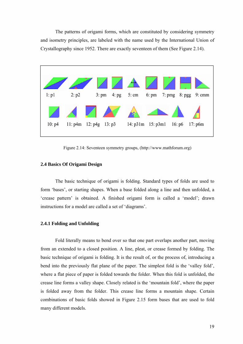
The patterns of origami forms, which are constituted by considering symmetry
and isometry principles, are labeled with the name used by the International Union of
Crystallography since 1952. There are exactly seventeen of them (See Figure 2.14).
Figure 2.14: Seventeen symmetry groups, (http://www.mathforum.org)
2.4 Basics
rigami is folding. Standard types of folds are used to
rm ‘bases’, or starting shapes. When a base folded along a line and then unfolded, a
‘crease
bend over so that one part overlaps another part, moving
om an extended to a closed position. A line, pleat, or crease formed by folding. The
basic te
Of Origami Design
The basic technique of o
fo
pattern’ is obtained. A finished origami form is called a ‘model’; drawn
instructions for a model are called a set of ‘diagrams’.
2.4.1 Folding and Unfolding
Fold literally means to
fr
chnique of origami is folding. It is the result of, or the process of, introducing a
bend into the previously flat plane of the paper. The simplest fold is the ‘valley fold’,
where a flat piece of paper is folded towards the folder. When this fold is unfolded, the
crease line forms a valley shape. Closely related is the ‘mountain fold’, where the paper
is folded away from the folder. This crease line forms a mountain shape. Certain
combinations of basic folds showed in Figure 2.15 form bases that are used to fold
many different models.
19

Figure 2.15: Basic folds, (Kenneway, 1997, pp. 8-10)
Huzita's Origami
iaki Huzita has formulated a set of
origami axioms what is currently the most powerful known. It is described in below.
2)
(Q4) (Q5) (Q6)
Figure 2.16: Huzita's Six Origami Axioms, (Takahashi, 2002, p. 4)
axioms on folding
The Italian-Japanese mathematician Hum
(Q1) (Q (Q3)
20

(O1) Given two points p1 and p2 we a a onnectinc n fold line c g them.
(O2) G
ld perpendicular to l1
point p2.
ine l2.
line and
e of three quite distinct kinds; natural, embedded and non-
cated. In the first two kinds of folding geometry, the folds and/or creases are
position
just the primary reference points (the original edges and corners of
the pap
by folding opposite edges onto each other and two creases obtained by folding
opposit
iven two points p1 and p2 we can fold p1 onto p2.
(O3) Given two lines l1 and l2 we can fold line l1 onto l2.
(O4) Given a point p1 and a line l1 we can make a fo
passing through the point p1.
(O5) Given two points p1 and p2 and a line l1 we can make a fold that places p1
onto l1 and passes through the
(O6) Given two points p1 and p2 and two lines l1 and l2 we can make a fold that
places p1 onto line l1 and places p2 onto l
From algorithmic point of view, these axioms imply two operations; finding a
folding the origami along the line (Takahashi, 2002, p. 4).
2.4.1.1 Folding Geometries
Folding geometries ar
lo
ed by using of location points. In the third kind of position, the folds and/or
creases are positioned by eye (though their positions may subsequently be refined by an
iterative process).
The natural folding geometry of a paper-shape is the folding geometry
obtained by using
er-shape) to determine where the creases will form. Various rectangles used as
starting shapes in modular origami and their folding geometries are briefly discussed in
below.
In the case of the square the natural folding geometry consists of two creases
obtained
e corners onto each other. The first set divides the square into four smaller
squares. The second set bisects these smaller squares at 45 degrees. This system of
natural folding geometry can be called the 90/45-degree system. The resulting crease
pattern is familiar as the crease pattern of the water bomb base and preliminary fold
(Figure 2.17.a). The natural folding geometry creates secondary reference points, which
can be used to locate further creases, such as those required for the bird base (Figure
2.17.b).
21

.
(a) (b) (c)
Figure : Natural folding g uare and recta e
)
The na e square. The
natural folding geometry the creases
ed by folding opposite corners together cross, or an angle at which the diagonals
cross - which is always the sam
the many interesting form
yields angles of 135/67.5/45 degrees.
ilar
folding geom
most common use of a non-located folding
geometry is that of dividing an edge or a crease into three roughly equal parts by means
2.17 eometries of sq ngl
(http://www.mizushobai.freeserve.co.uk/natural.htm
tural folding geometry of rectangles is more complex than th
of a rectangle is determined by an angle at which
form
e (Figure 2.17.c).
The Silver Rectangle has sides in the proportion of 1:sqrt2. The natural folding
geometry of the silver rectangle yields angles of 110/70/55 degrees. These angles are
found in the structure of the tetrahedron, the cube and the cuboctahedron as well as in
s known as rhombic polyhedra.
The Bronze Rectangle has sides in the proportion of 1:sqrt3 and its natural
folding geometry yields angles of 120/60/30 degrees. The bronze rectangle is its own
triple.
The Leftover Rectangle is the rectangle left over when the largest possible
square is removed from a silver rectangle. The leftover rectangle has sides in the
proportion of 1:1+sqrt2 and naturally
The Platinum Rectangles naturally yield the 108/72/36-degree angles required
for modeling polygons and polyhedra related to the regular pentagon. The platinum
rectangles are little used in modular origami design, since it is easy to generate a sim
etry from the 3x1 rectangle and the square.
The Golden Rectangle has sides in the golden proportion of 1:1.618. There are
only a few modular origami designs, which make use of the natural folding geometry of
this rectangle.
Embedded folding geometry is natural to one particular paper-shape can also
be embedded (by means of a careful choice of secondary reference points) within a
shape to which it is not natural. The
22
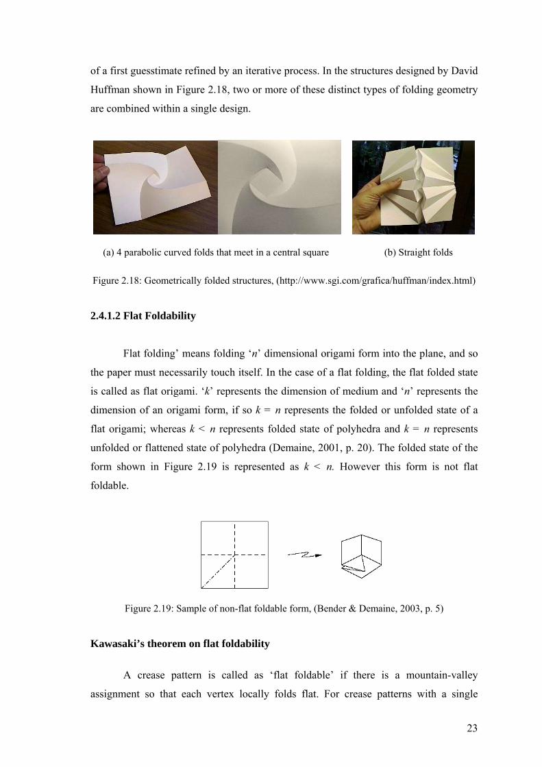
of a first guesstimate refined by an iterative process. In the structures designed by David
Huffman shown in Figure 2.18, two or more of these distinct types of folding geometry
are combined within a single design.
(a) 4 parabolic curved folds that meet in a central square (b) Straight folds
Figure 2.18: Geometrically folded structures, (http://www.sgi.com/grafica/huffman/index.html)
2.4.1.2 Flat Foldability
the paper must necessarily touch itself. In the case of a flat folding, the flat folded state
‘k’ represents the dimension of medium and ‘n’ represents the
imension of an origami form, if so k = n represents the folded or unfolded state of a
flat ori
Figure 2.19: Sam ine, 2003, p. 5)
Kawa
A crease pattern is called as ‘flat foldable’ if there is a mountain-valley
assignment so that each vertex locally folds flat. For crease patterns with a single
Flat folding’ means folding ‘n’ dimensional origami form into the plane, and so
is called as flat origami.
d
gami; whereas k < n represents folded state of polyhedra and k = n represents
unfolded or flattened state of polyhedra (Demaine, 2001, p. 20). The folded state of the
form shown in Figure 2.19 is represented as k < n. However this form is not flat
foldable.
ple of non-flat foldable form, (Bender & Dema
saki’s theorem on flat foldability
23

vertex, it is relatively easy to characterize flat foldability. Without specified crease
s flat-foldable precisely if the alternate angles
round the vertex sum to 180◦. Mathematical formulization and graphical representation
of Kaw
Figure 2.20: , (Demaine, 2001, p. 26)
‘Miura Ori Technique’, which was developed by a Japanese scientist Kouryou
M
are diagonal or zigzag. The horizontal folds are straight with an alternating valley and
e vertical lines that come in zigzag fold as
ountain or valley all the way across. Using the same system in a straight fold grid, the
transmi
Figure 2.21: Miura Ori Map Folding, (Bain, 1980, p. 1)
directions, a single-vertex crease pattern i
a
asaki’s theorem are shown in Figure 2.20 (Demaine, 2001, p. 26).
A flat-foldable vertex: θ1 +θ3 +… = θ2 +θ4 +… = 180◦
2.4.1.3 Miura Ori Flat Folding Technique
iura in 1980, is made up of a series of folds that follow a grid where the vertical lines
mountain fold given by the zigzag, that is, th
m
ssion of the movement is irregular and jams the system. The zigzag lines make
the intersections displace one another thus avoiding friction and stress between them,
which makes it more resistant at those points. When Miura Ori is applied on other
materials such as metals, it allows the use of hinges that do not have friction among
them, and then the material stress is also avoided. If Miura Ori Technique is applied to a
map (see Figure 2.21), it allows instant opening by just pulling apart two corners and
collapsing the map back equally fast and easy (Bain, 1980, p. 1).
24

2.4.1.4 Wrapping Fold
Wrapping fold is considered as different way of packaging a flat and thin
edium. Instead of folding it flat, it is wrapped around a central circular hub as shown
in Figure 2.22. It symmetric set of
.
m
can be seen that the folding pattern consists of a
mountain and valley folds
Figure 2.22: Wrapping Fold around a central hub, (Pellegrino & Vincent, 1998, p. 12)
This packaging scheme was firstly invented by Huso in 1960 for folding
compactly the tarpaulin top cover of a car, then, in 1989, this folding pattern was
proposed for the packaging of a solar sail by Temple and Oswald. Then, In 1992, a
simil ed
round a prismatic hub with 2n sides, developed by Guest and Pellegrino. .An example
of this
ar pattern with n straight mountain and n straight valley folds, which are wrapp
a
wrapping fold pattern shown Figure 2.23 is almost fully deployed, and almost
fully folded (Pellegrino, 1998, p. 12).
Figure 2.23: Wrapping Fold around a central prismatic hub, (Pellegrino & Vincent, 1998, p. 14)
2.4.1.5 Unfolding and Flattening Polyhedra
A classic open problem is whether the surface of every convex polyhedron can
be cut along some of its edges and unfolded into one flat piece without overlap. Such
25

edge unfolding has important practical applications in the field of packaging and sheet
nufacturing applications, it is considered that keeps the faces rigid and
avoids crossings in a folding process of a polygon into a polyhedron, or a continuous
unfoldi
metal bending.
A standard method for building a model of a polyhedron is to cut out a flat
unfolding, then, fold it up, and glue the edges together so as to make precisely the
desired surface. Given the polyhedron of interest, a natural problem is to find a suitable
unfolding. In ma
ng of a polyhedron into a polygon (Demaine, 2001, pp. 29-35).
Figure 2.24: Unfolding of an octahedron, (Demaine, 2001, p. 35)
The flattening problem is flatten the polyhedral complex into a flat folded state without
cutting or stretching the paper. Intuitively, flattening can be achieved by applying force
to the polyhedral model, but in practice this can easily lead to tearing the medium.
Instead of app iece of pape
and fold it as in flat origami (Demaine, 2001, p. 36).
Figure 2.25: Flattening a tetrahedron, from left to right, (Demaine, 2001, p. 36)
2.4.2 Base
simply r most
common bases, from simplest to the more complex, are the ‘kite base’, the ‘fish base’,
e’ and the ‘frog base’.
lying force, it should better to treat a polyhedral surface as ap r
Standard types of folds are used to form bases, or starting shapes. A base is
a geometric shape that resembles the subject to be folded. The fou
the ‘bird bas
26
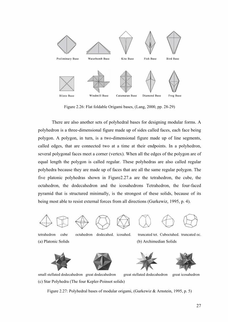
Figure 2.26: Flat foldable Origami bases, (Lang, 2000, pp. 28-29)
There are also another sets of polyhedral bases for designing modular forms. A
polyhedron is a three-dimensional figure made up of sides called faces, each face being
polygon. A polygon, in turn, is a two-dimensional figure made up of line segments,
called edges, that are connected two at a time at their endpoints. In a polyhedron,
several polygo lygon are of
qual length the polygon is called regular. These polyhedras are also called regular
polyhed
nal faces meet a corner (vertex). When all the edges of the po
e
ra because they are made up of faces that are all the same regular polygon. The
five platonic polyhedras shown in Figure2.27.a are the tetrahedron, the cube, the
octahedron, the dodecahedron and the icosahedrons Tetrahedron, the four-faced
pyramid that is structured minimally, is the strongest of these solids, because of its
being most able to resist external forces from all directions (Gurkewiz, 1995, p. 4).
tetrahedron cube octahedron dodecahed. icosahed. truncated tet. Cuboctahed. truncated oc.
(a) Platonic Solids (b) Archimedian Solids
small stellated dodecahedron great dodecahedron great stellated dodecahedron great icosahedron
Figure 2.27: Polyhedral bases of modular origami, (Gurkewiz & Arnstein, 1995, p. 5)
(c) Star Polyhedra (The four Kepler-Poinsot solids)
27

Other sets of solids can be obtained from the Platonic Solids, which are so-
called Archimedean Solids (Figure 2.27.b). They are semi–regular polyhedra; in such a
is more than one polygon in a
lids derived from platonic solids by
exten
ease pattern is obtained. Crease patterns
represe
with two different line-styles,
in such a way that a dashed line indicates a lley fold -a concave crease, whereas a line
icates a mountain fold-a convex crease (see Figure 2.28). When
ese two systems of lines intersect, they form self-similar surface elements, to be called
way that all faces are regular polygons, but there
particular solid, and all vertices are identical.
Star polyhedras are another set of so
ding the faces of each to form a star (Figure 2.27.c).
2.4.3 Crease Pattern
When a base folded and then unfolded, a cr
nted by two systems of lines that represent hills and valleys in the 3 dimensional
configurations. These lines are usually indicated on paper
va
of dots and dashes ind
th
here tiles. The shape of the tiles that occur in this manner is polygonal with or without
side regularity. A crease pattern displays several types of symmetric organizations
(Liapi, 2002, p. 387).
(a) Preliminary base (b) Waterbomb base
Figure 2.28: Crease pattern, (http://www.mizushobai.freeserve.co.uk/technicalmanual.htm)
2.4.4 Origami Tessellations
Literally, ‘tessellate’ means to form all squares in a mosaic pattern.
nglish means
‘fo ,
the geometric meaning of the verb tessellate is to cover the plane with a geometric
or polygon in such a way as to leave no spaces between
e meeting-points of their vertices. (Critchlow, 1969, p. 60)
or arrange sm
The word ‘tessellate’ is derived from Greek word ‘tesseres’, which in E
ur’. Since a mosaic extends over a given area without leaving any region uncovered
pattern that has regular shapes
th
28
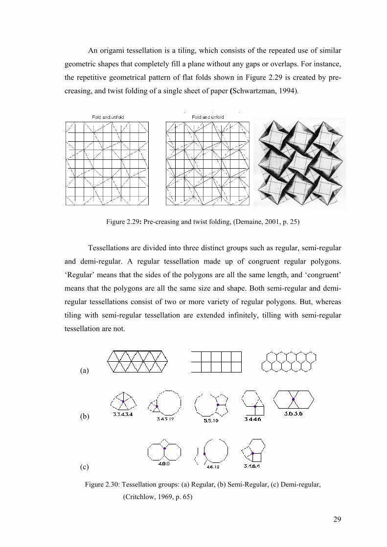
An origami tessellation is a tiling, which consists of the repeated use of similar
geometric shapes that completely fill a plane without any gaps or overlaps. For instance,
the repetitive geometrical pattern of flat folds shown in Figure 2.29 is created by pre-
creasing, and twist folding of a single sheet of paper (Schwartzman, 1994).
Figure 2.29: Pre-creasing and twist folding, (Demaine, 2001, p. 25)
i-regular
de up of congruent regular polygons.
e length, and ‘congruent’
Tessellations are divided into three distinct groups such as regular, sem
and demi-regular. A regular tessellation ma
‘Regular’ means that the sides of the polygons are all the sam
means that the polygons are all the same si i-regular and demi-
regular tesse ut, whereas
tiling with semi initely, tilling with semi-regular
tessella
ze and shape. Both sem
llations consist of two or more variety of regular polygons. B
-regular tessellation are extended inf
tion are not.
(a)
(b)
(c)
Figure 2.30: Tessellation groups: (a) Regular, (b) Semi-Regular, (c) Demi-regular,
(Critchlow, 1969, p. 65)
29

As a rule of thumb, a tessellation is named in respect of how many polygons
surrounding a vertex, and how many sides has each polygon by considering the
(Critchlow, 969, p.
5).
clockwise and beginning with the polygon that has the fewest side 1
6
(a) Regular tessellations with straight line
(b) Non-regular Tessellations with curved line
Figure 2.31: Tessellations designed by Enlai Hooi, (http://www.enlaihooi.com/images/jpges)
There is also a recent trend results from the studies on curved line folding in
computational origami: Creating pattern that ha
ganic and inherently structural origami
surfaces design by Enlai Hooi in 2000.
2.5 Classification of Origamic Structure
to number of sheets used. In other words, origami structures are divided into two
distinct
s curved line or both curved and straight
line. The samples shown in Figure 2.31.b are or
In the scope of this thesis, origamic structures are mainly categorized according
categories, in such a way that, single sheet structures that whose constructions
are entirely made on a single piece of sheet, and modular structures that whose
30

constructions are made on two or more pieces of sheet. And also, single piece
constructions are taken up as deployable planar structures, and then discussed in three
lateral types such as pop-up structures, biomimetic folding patterns and deployable
2.5.1 D
a planar paper surface in unfolded state, then transforms to a three-
dimensional object by folding. Principles of the origami design and math can find
(transformable) structures for
rchitectural and industrial product. These structures are driven primarily by a
fundam
s for folding or unfolding origami structures are possible. In
the firs
ra-Ori folding pattern, and origami tessellations, which
were d
This structure erects fully when two adjacent
cylinders.
eployable (Transformable) Planar Structures
Transformable structures are defined as structures that are capable of executing
large configuration changes in an autonomous manner. The configuration of such
structures change between a compact-packaged state, and a large-deployed state
(Pelegrino, 2001, p. 148).
Similar concepts of spatial transformation are encountered in the origami form,
which has
applications in the conception and design of deployable
a
ental concept of geometric change and they provide a new approach to a
common packaging problem.
An observation of the kinematics of different origamic structures shows that at
least two different method
t, the model unfolds in a sequential fashion, which the distinct steps must be
followed each other, and each new step starts when the motion of the previous has been
completed. In the second, the structure deploys synchronously. The latter means that all
tiles move at the same time, and the motion of one affects the motion of all other tiles
adjacent to it (Liapi, 2002, pp. 385-388).
In these contexts, in addition to the structures and patterns discussed below,
wrap folding pattern, the Miu
iscussed beforehand in section 2.4.1 and 2.4.4, also constitute the synchronously
deploying structures.
2.5.1.1 Pop-Up Structures
‘Pop-up structure’ is defined as a self-erecting, three-dimensional structure,
formed by the action of opening a crease.
31

base pa
hese sections and strips are folded, and then, the whole sheet is
folded to rise up the pop-ups and make the creation three-dimensional.
an be classified by the angle of opening two base pages, on
hich the pop-up structure sits, specifically at 90°, 180° and 360°. These are the angles
at whic
mainly for 90°
one-pie
re in Figure 2.32.c is made up of two-level.
The pro
Figure 2.32: Pop-up structures, (Tor* & Mak* & Lee, 2003, p. 3)
ges, on which it sits, are opened to a right angle. Paper folding and cutting is
integrated with these structures to achieve pop-up effects. In such a way that a piece of
sheet is first cut into a predetermined pattern. This separates the sheet into various
sections and strips. T
Collapsible pop-ups c
w
h the pop-ups are fully erected. Some pop-ups are termed with 0°. In other
words, there is no folding of base pages, but layers of cut papers overlapping on top of
one another with some protruding portions.
Pop-up structures are forming by folding and cutting techniques that is similar to
Kirigami, but becoming different in sequence. In Kirigami (see Figure 2.2 and
Figure2.6), the folding comes before the cutting. On the contrary, in pop-up structure
folding comes after the cutting or slitting. Techniques with slitting are
ce type. These include the single slit (Figure 2.32.a) and double slits (Figure
2.32.b). Variations can be achieved by altering the length and shape of the slit lines.
A pop-up structure can be made up of different number of pop-up levels. A pop-
up level is a layer of pop-up pieces built over the gutter crease or existing creases on
other pop-up layers. For example, the structu
cess of developing a pop-up level over a crease is termed as a crease initiation.
There are two types of crease initiations for a pop-up level: a mountain crease or a
valley crease. In Figure 2.32.c, the first pop-up level is developed by a mountain crease
initiation, and the second level is developed by a valley crease initiation, whereas the
both two pop-up levels in Figure 2.32.d developed by mountain crease initiations.
(a) (b) (c) (d)
(a) A pop-up made from a single slit. (b) A pop-up constructed from double slits. (c) The first
pop-up level is a mountain crease initiation and second level is a valley crease initiation. (d) A
pop-up structure with double mountain crease initiation.
32

(a) Single slit pop-up with a vertex fold (b) Double slit pop-up with pleats
Figure 2. 03, p. 6)
the planar pieces to create additional pop-up
specific technique to fold the planar pieces
structure from erecting properly. The feasible m ountain-
valley assignm
creases reverse
foldin rtex
folds or pleats. A flat vertex fold has crease eet at a vertex whereas those of
pleats d
ed parallel lateral secondary veins, generate a corrugated surface
igure 2.34). This simple and regular corrugated folding patterns and mechanisms can
nal foldable and deployable structures such as
lar panels and lightweight antennae of satellites, or for the folding of deployable
membr
33: Additional pop-up effects by folding, (Tor* & Mak* & Lee, 20
After a basic pop-up structure has been developed, it is possible to further fold
effects (Figure 2.33). However, there is a
, for other folding methods would hinder the
ethod is by changing the m
ent of an existing crease on the pop-up structure and creating two new
at the same time. In origami idiom, this folding method is known as ‘
g’ (see Figure 2.15). Reverse folding on pop-up structures can produce flat ve
lines that m
o not. Consequently, pop-up structures are flat foldable in un-erected state, and
when erected they are deployable into three dimension synchronously (Tor*, Mak*,
Lee, 2003, pp. 2-6).
2.5.1.2 Biomimetic Folding Patterns
The folds patterns of origami-type structure have presented in this section are
‘biomimetic’, in such a way they were developed by considering how the folding of a
natural structure -a leaf. The leaves of most plants are folded or rolled while still inside
the bud. The unfolding of a hornbeam leaf with a straight central primary vein and
symmetrically arrang
(F
suggest ideas for the design of polygo
so
anes such as tents, clothes or other coverings. Leaves of hornbeam could be
modeled as plane surfaces, with straight parallel folds. The lateral veins, when the
leaves are outstretched, are angled at 30-50° from the center vein. A higher angle allows
33
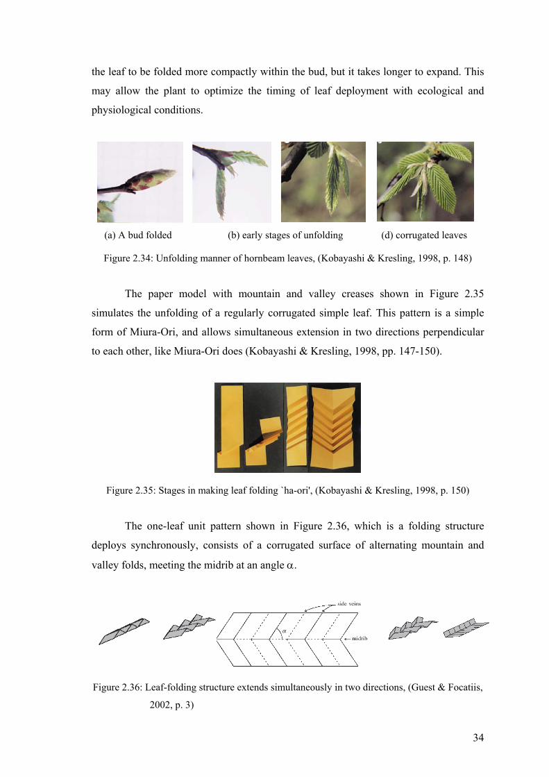
the leaf to be folded more compactly within the bud, but it takes longer to expand. This
may allow the plant to optimize the timing of leaf deployment with ecological and
physiological conditions.
(a) A bud folded (b) early stages of unfolding (d) corrugated leaves
Figure 2.34: Unfolding manner of hornbeam leaves, (Kobayashi & Kresling, 1998, p. 148)
mulates the unfolding of a regularly corrugated simple leaf le
rm of Miura-Ori, and allows simultaneous extension in two directions perpendicular
each other, like Miura-Ori does (Kobayashi & Kresling, 1998, pp. 147-150).
The paper model with mountain and valley creases shown in Figure 2.35
si . This pattern is a simp
fo
to
Figure 2.35: Stages in making leaf folding `ha-ori', (Kobayashi & Kresling, 1998, p. 150)
The one-leaf unit pattern shown in Figure 2.36, which is a folding structure
deploys synchronously, consists of a corrugated surface of alternating mountain and
valley folds, meeting the midrib at an angle α.
Figure 2.36: Leaf-folding structure extends simultaneously in two directions, (Guest & Focatiis,
2002, p. 3)
34
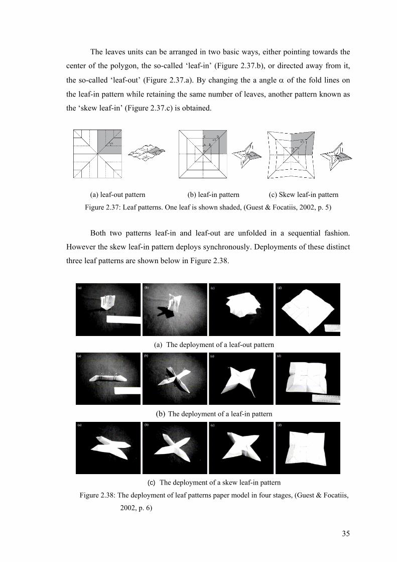
The leaves units can be arranged in two basic ways, either pointing towards the
center of the polygon, the so-called ‘leaf-in’ (Figure 2.37.b), or directed away from it,
the so-called ‘leaf-out’ (Figure 2.37.a). By changing the a angle α of the fold lines on
the leaf-in pattern while retaining the same number of leaves, another pattern known as
e ‘skew leaf-in’ (Figure 2.37.c) is obtained.
hronously. Deployments of these distinct
three leaf patterns are shown below in Figure 2.38.
th
(a) leaf-out pattern (b) leaf-in pattern (c) Skew leaf-in pattern
Figure 2.37: Leaf patterns. One leaf is shown shaded, (Guest & Focatiis, 2002, p. 5)
Both two patterns leaf-in and leaf-out are unfolded in a sequential fashion.
However the skew leaf-in pattern deploys sync
(a) The deployment of a leaf-out pattern
(b) The deployment of a leaf-in pattern
(c
Figure 2.38: The deployment of leaf patterns paper model in four stages, (Guest & Focatiis,
2002, p. 6)
) The deployment of a skew leaf-in pattern
35
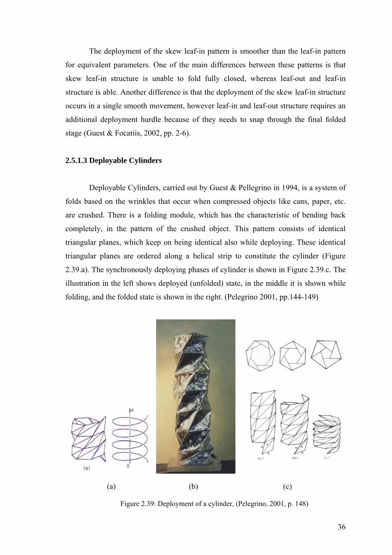
The deployment of the skew leaf-in pattern is smoother than the leaf-in pattern
for equivalent parameters. One of the main differences between these patterns is that
skew leaf-in structure is unable to fold fully closed, whereas leaf-out and leaf-in
structure is able. Another difference is that the deployment of the skew leaf-in structure
occurs in a single smooth m t structure requires an
additional deployment hurdle because of they needs to snap through the final folded
stage (Guest & Focatiis, 2002, pp. 2-6).
2.5.1.3 Deployable Cylinders
folds based on the wrinkles that occur when compressed objects like cans, paper, etc.
are cru
the right. (Pelegrino 2001, pp.144-149)
ovement, however leaf-in and leaf-ou
Deployable Cylinders, carried out by Guest & Pellegrino in 1994, is a system of
shed. There is a folding module, which has the characteristic of bending back
completely, in the pattern of the crushed object. This pattern consists of identical
triangular planes, which keep on being identical also while deploying. These identical
triangular planes are ordered along a helical strip to constitute the cylinder (Figure
2.39.a). The synchronously deploying phases of cylinder is shown in Figure 2.39.c. The
illustration in the left shows deployed (unfolded) state, in the middle it is shown while
folding, and the folded state is shown in
(a) (b) (c)
Figure 2.39: Deployment of a cylinder, (Pelegrino, 2001, p. 148)
36

37
2.5.2 Modular Structures
In origami, the word ‘module’ implies the units that are repeatedly attached in
order to construct complex forms. These units has simple structure, which are either all
identical or occur in sets of different complementary units.
‘Modular structures’ are obtained by a two stage folding technique of multiple pieces of
sheets. In the first stage each piece of sheet is folded into a module, and secondly the
modules are assembled into an integrated flat shape or three-dimensional structure.
While the one set of modules form the visible surface, another set are used to link them
together. In most cases the design of the modules integrates the two or more elements
into a seamless whole.
Modular pattern is flat folded modular struc s. Modular patterns divide the
rstand modular
patterns it is necessary to consider the distinction between plain and contrast modules.
ogeneous; on the contrary a
contrast module’s visible surface is differentiated. Differentiation of the surface of a
odule
(a) Multi-color (b) Contrast (c) Multi-color contrast
Figure 2.40: Modular patterns, (http://www.mizushobai.freeserve.co.uk/technicalmanual.htm)
ture
visible surface of the form into visually distinct regions. In order to unde
A plain module is a module whose visible surface is hom
m is achieved by using two sides colored medium, and forming the visible surface
of the module by using both surfaces of the medium.
Three different kinds of modular pattern are ‘multi-color pattern’, ‘contrast
pattern’, ‘multi-color contrast pattern’. Multi-color patterns are patterns formed by
combining plain modules, which is folded from two sides colored medium. Contrast
patterns are patterns formed by combining contrast modules, each of which is folded
from an identical one side colored medium. Multi-color contrast patterns are formed by
combining contrast modules that folded from one side colored mediums in two distinct
colors.

Figure 2.41: Two Fold Star, (http://www.mizushobai.freeserve.co.uk/technicalmanual.htm)
Two Fold Star shown in Figure 2.41 designed by David Mitchell, is another
example of multi-color contrast pattern made by combining eight modules that each one
is produced from a silver triangle using only two folds. Modular structures shown in
Figure 2.42 have infinitely extensible origamic surfaces, which are capable of being
extended without limit in all directions.
Figure 2.42: Modular surfaces, (http://www.enlaihooi.com/images/jpges/)
Modular polhedras are constituted by using identical multiple sheets in
different colors, which are f
integrated second-generation structures.
Polyhedral combinations are forms created by combining several simple polyhedral
forms to create a more complex shape. Edge-to-edge combination of four cubes is
shown in Figure 2.43.c. The modular structures like containers or boxes called as Non-
Polyhedral forms. The triangular lidded box shown in Figure 2.43.e is a design by
Tomoko Fuse.
olded into similar units with identical starting shapes.
Polyhedral forms shown in Figure 2.43.a provides an excellent way to model many
Platonic, Archimedean, rhombic and other polyhedras. Macro-modular forms shown in
Figure 2.43.b are a development of modular origami in which a number of complete
modular assemblies are combined to form
38
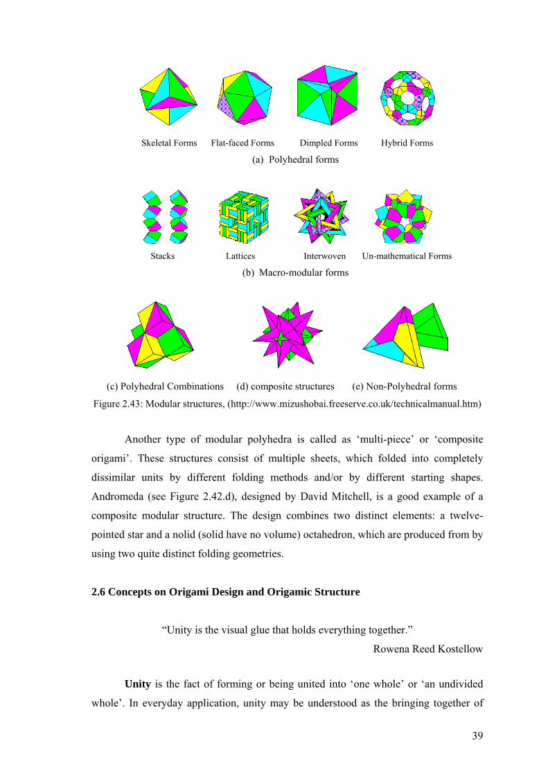
Skeletal Forms Flat-faced Forms Dimpled Forms Hybrid Forms (a) Polyhedral forms
Stacks Lattices Interwoven Un-mathematical Forms
(b) Macro-modular forms
(c) Polyhedral Combinations (d) composite structures (e) Non-Polyhedral forms
Figure 2.43: Modular structures, (http://www.mizushobai.freeserve.co.uk/technicalmanual.htm)
Another type of modular polyhedra is called as ‘multi-piece’ or ‘composite
origami’. These structures consist of multiple sheets, which folded into completely
dissimilar units by different folding methods and/or by different starting shapes.
Andromeda (see Figure 2.42.d), designed by David Mitchell, is a good example of a
composite modular str . The desi bines two distinct elements: a twelve-
pointed star and a nolid (solid have no vol by
using two quite distinct folding geom
2.6 Concepts on Origami Design and Origamic Structure
“Unity is the visual glue that holds everything together.”
Unity is the fact of forming or being united into ‘one whole’ or ‘an undivided
whole’. In everyday application, unity may be understood as the bringing together of
ucture gn com
ume) octahedron, which are produced from
etries.
Rowena Reed Kostellow
39

many things into an arrangement that makes them appear as one, with all that so saying
implies for harmony, cohesion, and accord. Unity, like integrity, denotes wholeness.
“Wholeness basically means the quality of being well shaped, both in reality
and in appearance, in the art criticism of the ancien (Johnson, 1994, p. 97). In
with
Simplicity is the form, state, or condition of being composed of a single
structur
he task (Johnson, 1994, p. 107).
Unity and simplicity have been equated in the underlying order to so-called Platonic
Abstraction is a term means literally ‘draw off’ besides ‘draw away from’.
What is drawn s, and what is
drawn away from is the concrete, complex, variegated, full-c
abstraction is achieved by using simple arrangement, primary forms, pure geometry,
and lig
se
differen
economic, aesthetic, political and contextual influence. A logic of
curvilin
ne another in order to construct complex forms. Usually the more
t Greeks”
design, it means that a completed structure consists of parts arranged in symmetry
the whole.
e and an absence of complexity, intricacy or adornment. The quest for unity and
purity in designing is usually linked with the achievement of simplicity in artifact.
Simplicity and homogeneity to give rise to purity through the clarity of function,
honesty of material, transparency of production, and the consistent application of
analytical methods
Simplicity does not imply a simple process, though it may be the result of one
that progressively and efficiently simplifies t
solids: the five regular polyhedra.
off is the essence, the distinguishable aspects of object
olor actuality. In design,
htness that satisfy bare necessities. Abstract shapes and forms are those in which
the essence of an object has been extracted and expressed (Johnson, 1994, pp. 331-332).
Pliancy is another concept that determines the embodiment and incorporation of
disparate elements by an external force. Smoothness implies pliant integration of the
ces rather than representing them by collision of forms. “The smooth spaces
described by these continuous yet differentiated systems result from curvilinear
sensibilities that are capable of complex deformations in response to programmatic,
structural
earity argues for an active involvement with external events in the folding,
bending, and curving of form.” (Muyan, 2003, pp. 102-103)
Modularity is a concept that inspirited from the richness of nature derives from
simple structures, such as cells, joined repeatedly to form elegant patterns. Modular
construction uses a relatively simple element, or module, and repeatedly attaches copies
of that element to o
40

module
dentical or
rom the same basic folds.
s or sets of modules that are attached, the more complex is the resulting form. In
origami however, the word 'module' still implies that the units are either all i
occur in sets of complementary units making up identical sub-assemblies or at the very
least are similar in that they begin f
41
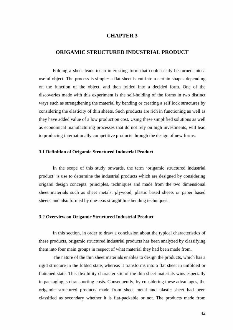
CHAPTER 3
ORIGAMIC STRUCTURED INDUSTRIAL PRODUCT
Folding a sheet leads to an interesting form that could easily be turned into a
useful object. The process is simple: a flat sheet is cut into a certain shapes depending
on the function of the object, and then folded into a decided form. One of the
discoveries made with this experiment is the self-holding of the forms in two distinct
ways such as strengthening the material by bending or creating a self lock structures by
considering the elasticity of thin sheets. Such products are rich in functioning as well as
they have added value of a low production cost. Using these simplified solutions as well
as economical manufacturing processes that do not rely on high investments, will lead
to producing internationally competitive products through the design of new forms.
3.1 Definition of Origamic Structured Industrial Product
In the scope of this study onwards, the term ‘origamic structured industrial
product’ is use to determine the industrial products which are designed by considering
origami design concepts, principles, techniques and made from the two dimensional
sheet materials such as sheet metals, plywood, plastic based sheets or paper based
sheets, and also formed by one-axis straight line bending techniques.
3.2 Overview on Origamic Structured Industrial Product
In this section, in order to draw a conclusion about the typical characteristics of
these products, origamic structured industrial products has been analyzed by classifying
them into four main groups in respect of what material they had been made from.
The nature of the thin sheet materials enables to design the products, which has a
rigid structure in the folded state, whereas it transforms into a flat sheet in unfolded or
flattened state. This flexibility characteristic of the thin sheet materials wins especially
in packaging, so transporting costs. Consequently, by considering these advantages, the
origamic structured products made from sheet metal and plastic sheet had been
classified as secondary whether it is flat-packable or not. The products made from
42

paper-based materials have not been classified in such a way, because all of them are
already flat packable.
3.2.1 Origamic Structured Sheet Metal Products
Because of their relatively low cost, high strength, and short lead times for
tooling, formed sheet are important to industrial designers. Sheet metal is used mostly in
large or small home appliances. It is also important in residential and office furniture or
accessories and in commercial showcase and displays.
Flat packables
Letter Holder Wall Mount Magazine Rack Desktop CD Holder
Figure 3.1: ‘2D:3D’ Office accessories, designed by Charlie Lazor, 1999, Manufacturer: Blu
Dot, (Byars, 2003, pp. 24-27)
‘2D:3D’ desktop accessories made from 0.9 mm cold-rolled powder coated steel
have a structure like pop-ups (see Section 2.5.1.1), in such a way the layers of certain
cuts are overlapped on top of one another with some protruding portions. These
products are purchased as flat pieces, and then end-users are expected to bend the
objects into shape. Hence the name of the collection is ‘2D:3D’, in other words, two
dimensions into three dimensions. ‘2D:3D’ products figure out how to keep two-
dimensional sheet flat and to let the consumer do the three-dimensional bending
operation. Cold-rolled steel is preferred by means of its elasticity in bending. The lines
43
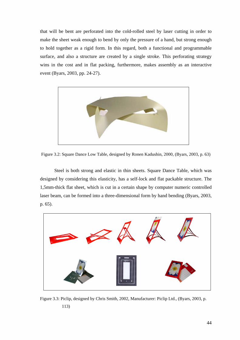
that will be bent are perforated into the cold-rolled steel by laser cutting in order to
make the sheet weak enough to bend by only the pressure of a hand, but strong enough
to hold together as a rigid form. In this regard, both a functional and programmable
surface, and also a structure are created by a single stroke. This perforating strategy
wins in the cost and in flat packing, furthermore, makes assembly as an interactive
event (Byars, 2003, pp. 24-27).
Figure 3.2: Square Dance Low Table, designed by Ronen Kadushin, 2000, (Bya
rs, 2003, p. 63)
designed by considering this elasticity, has a self-lock and flat packable structure. The
1,5mm
Steel is both strong and elastic in thin sheets. Square Dance Table, which was
-thick flat sheet, which is cut in a certain shape by computer numeric controlled
laser beam, can be formed into a three-dimensional form by hand bending (Byars, 2003,
p. 65).
clip, designed by Ltd., (Byars, 2003, p.
113)
Figure 3.3: Pi Chris Smith, 2002, Manufacturer: Piclip
44

Piclip is a frame made from 0.25 mm brushed stainless steel that designed to be
supplied with its own envelope and sent flat through the post. The recipient then bends
the pic
Figure 3.4: Prism u Noguchi, 1957, Manufacturer: Alcoa
(http://www.hivemodern.com)
Prismatic Table was designed in 1957 to explore new uses for aluminum. Its
design philosophy is originated from the ancient Japanese art of paper folding translated
to the m
Figure 3.5: Fly,
(
lip and inserts the photo. Owing to the elasticity of the thin steel sheet, Piclip
always return to its original flat form. Its springy structure is obtained by punched out
‘U’ shape in one direction, another ‘U’ shape punched out in the opposite direction.
Non-flat packables
atic Table, designed by Isam
odern Western material of metal. This table has a polyhedral modular structure
(see Section 2.5.2) consists of three identical unit forms, which is bent in exactly same
manner.
designed by Mehmet Ermiyagil, 2004, Manufacturer: Derin Design
http://www.derindesign.com)
45

Fly low table was designed by considering the Blintz fold, which is one of the
basic folds of o ee Figure 2.15) is a technique that is the
folding
c
techniques of origami design: cutting and folding. In spite of Tufold has a light
aesthet
gil
(http://www.trendsettermag.com/template.asp?baslik_id=567)
rigami design. Blintz fold (s
of all four corners of a square into the center. The form is pretending to be a flat
foldable paper. By means of its geometric structure, Fly denotes great simplicity and
integrity in designing process, in manufacturing process, and also in functioning.
Figure 3.6: Tufold, By Scot Laughton, (http://www.nienkamper.com/product.asp?prodcat=)
The single sheet of aluminum cutout is formed into a table by the basi
ic; the strength of the material is increased by one axis line bending process in
both two sides.
Figure 3.7: Origami P1 Table, AD Design Fair 2004: Best Designer Award, by Mehmet Ermiya
46

In the design of P1 Origami Table, the traditional material had been taken up in
the assis (see Section 2.1.2).
Althou
These multipurposed table systems shown in Figure 3.8 and Figure 3.9 are
form ing
angles.
unusual manner. The unfolded polygonal crease pattern of this table has been created by
ting of TreeMaker computer based origami design tool
gh it is plain and systematic, its structure makes the watcher curious.
Figure 3.8: Noan, designed by Gualtiero Sacchi, 2004, (http://www.moreproject.com)
ed by a combination of v die bendings (see Section 3.3.1.3) at different bend
Figure 3.9: Diana side table series, Red Dot Award: Product Design 2002, designed by
Konstantin Grcic, 2002, Manufacturer: ClassiCon, (http://www.reddot.de)
47
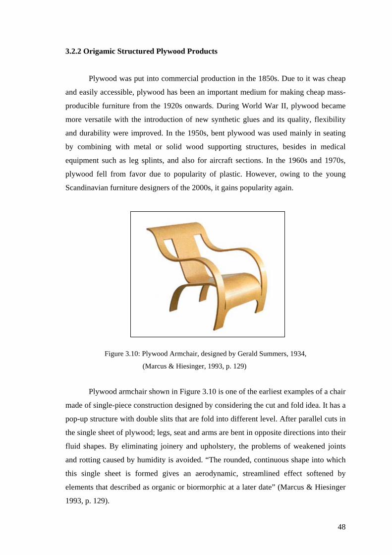
48
3.2.2 Origamic Structured Plywood Products
Plywood was put into commercial production in the 1850s. Due to it was cheap
and easily accessible, plywood has been an important medium for making cheap mass-
prod me
more vers lexibility
t plywood was used mainly in seating
y combining with metal or solid wood supporting structures, besides in medical
equipm
Figure 3.10: Ply rs, 1934,
Plywood arm ples of a chair
made of single-piece constructi
the single sh s into their
fluid shapes. By eliminating joinery and upholstery, the problems of weakened joints
and rotting caused by humidity is avoided. “The rounded, continuous shape into which
this si
ucible furniture from the 1920s onwards. During World War II, plywood beca
atile with the introduction of new synthetic glues and its quality, f
and durability were improved. In the 1950s, ben
b
ent such as leg splints, and also for aircraft sections. In the 1960s and 1970s,
plywood fell from favor due to popularity of plastic. However, owing to the young
Scandinavian furniture designers of the 2000s, it gains popularity again.
wood Armchair, designed by Gerald Summe
(Marcus & Hiesinger, 1993, p. 129)
chair shown in Figure 3.10 is one of the earliest exam
on designed by considering the cut and fold idea. It has a
pop-up structure with double slits that are fold into different level. After parallel cuts in
eet of plywood; legs, seat and arms are bent in opposite direction
ngle sheet is formed gives an aerodynamic, streamlined effect softened by
elements that described as organic or biormorphic at a later date” (Marcus & Hiesinger
1993, p. 129).

Non-flat packables but impressively stockables
Due to the nature of the bent plywood, the product made from plywood has
strength rigidity. Consequently, in order to get advantage in packaging or transporting,
it should better considering to design it stockable or modular. In this regard, it can be
said that the modular structure shown in Figure 3.11 is almost flat foldable, and the
others shown in Figure 3.12 and Figure 3.13 are impressively stockable.
Figure 3.11:
The stool'
"fingers" ma an
ingeniously stable and rem
Figure 3.12: Bend Table, designed by Mehmet Ermiyagil, 2000
(http://www.derindesign.com)
Capelli Stool, IDEA Industrial Design Excellence Award 2002: Silver, designed by
Carol Catalano, 2002, (http://www.idsa.org)
s design consists of two identical bent plywood pieces with undulating
tched at the top. The pieces interlock without tools or fasteners to form
arkably strong structure. It unfolds and the two halves stack
together conveniently for easy shipping and storage.
49

(a) Eco chair, iF Ecology
(b) Tri chair
Figure 3.13: Voxia Series, d ttp://www.scandinaviandesign.com)
Eco ch l of the bent
lywood. To constitute this pop-up structure, two parallel slits cut to form thin back
es at near right angles. Tri
chair creates origam
ously in the public’s
be made from
products need minimal investment in tooling. As a result it has become extensively used
processes that can be used to give this material endless potential to create new forms for
everyday products. (Lefteri C., 2001; pp. 45-50)
Design Award 2000: Best of category
esigned by Peter Karpf 2000, (h
air is an image of the ecological and economical potentia
p
legs, and then this single piece of plywood is folded three tim
i-like space and depth out of a curved surface.
3.2.3 Origamic Structured Plastic Sheet Products
Polyprophlene sheets have been around virtually anonym
knowledge since 1950s. As sheet it has provided the opportunity for plastic products to
paper process like folding, cutting and creasing with the result that
in all forms of packaging. Polypropylene sheets offer a range of colors and printing
50
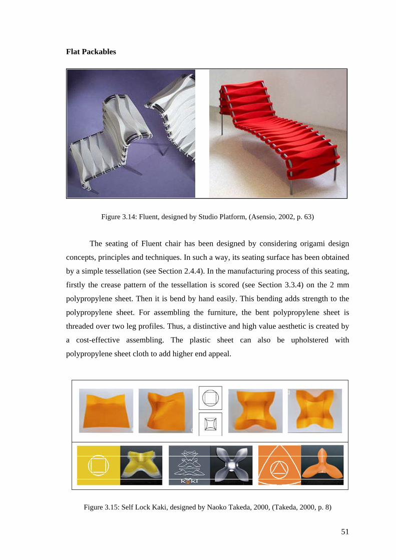
Flat Pa
The seating of Fluent chair has been designed by considering origami design
Figure 3.15: Self Lock Kaki, designed by Naoko Takeda, 2000, (Takeda, 2000, p. 8)
ckables
Figure 3.14: Fluent, designed by Studio Platform, (Asensio, 2002, p. 63)
concepts, principles and techniques. In such a way, its seating surface has been obtained
by a simple tessellation (see Section 2.4.4). In the manufacturing process of this seating,
firstly the crease pattern of the tessellation is scored (see Section 3.3.4) on the 2 mm
polypropylene sheet. Then it is bend by hand easily. This bending adds strength to the
polypropylene sheet. For assembling the furniture, the bent polypropylene sheet is
threaded over two leg profiles. Thus, a distinctive and high value aesthetic is created by
a cost-effective assembling. The plastic sheet can also be upholstered with
polypropylene sheet cloth to add higher end appeal.
51

The ‘Self Lock Kaki’ shown in Figure 3.15 is a self lock container made from
polypropylene sheet .The principle behind it lies in the variation in the dimension of the
curves, the length of the straight lines and the number of lines that make the unit, thus
obtaining greater efficiency in the lock. The Self-lock Kaki responds when the curve
and the straight folds intersect each other, even in an imaginary way, for example on a
aper, the Self-lock Kaki can be obtained with a curve and a straight line acting as a
chord. If the straight line is not chord of the curve, there will be no self-hold. The effect
is also dependent on the radius of the curve, the position with respect to the straight line
and the material employed. Taking this as a pattern, and activating the folds, the
following sequence results in the kaki container. If a force is applied in a well
distributed manner across its surface, the self hold is reaffirmed, but if a vertical force is
applied in the center of the folds, the Self-lock Kaki lose their effect, and the material
returns to its original state The result is a self-locking, hinge and clip structure. Curved
folding bends toward the opposite direction against the straight folding. Once folded,
e structure converts into clip and hinge. By simply pressing the two extremes of the
hinge . As
the rad
p
th
with fingers, the clip opens and by loosening it returns to the original position
ius of the curve turns smaller, the container will be deeper. It doesn’t require any
type of slit or utilize any technique of joint, such as adhesive or glue, thermal sealing,
soldering or any other extra elements like staple, screw, nails, rivet, etc. (Takeda, 2000,
pp. 2-10).
The City Knife II shown in Figure 3.16 and the flat foldable sandal shown in
Figure 3.17 are other examples of flat packable products. These products express how
the flat packability concept is find application in two distinct manners.
Figure 3.16: City Knife II, designed by Kirsten Schambra, 1998, Manufacturer: Nike
(http://www.metropolismag.com/html/content_1203/nik/htm)
52
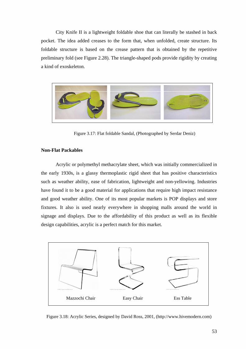
City Knife II is a lightweight foldable shoe that can literally be stashed in back
pocket. The idea added creases to the form that, when unfolded, create structure. Its
foldabl
Figure 3.17: Flat foldable Sandal, (Photographed by Serdar Deniz)
Non-Flat Packables
Acrylic o mercialized in
the ear
e structure is based on the crease pattern that is obtained by the repetitive
preliminary fold (see Figure 2.28). The triangle-shaped pods provide rigidity by creating
a kind of exoskeleton.
r polymethyl methacrylate sheet, which was initially com
ly 1930s, is a glassy thermoplastic rigid sheet that has positive characteristics
such as weather ability, ease of fabrication, lightweight and non-yellowing. Industries
have found it to be a good material for applications that require high impact resistance
and good weather ability. One of its most popular markets is POP displays and store
fixtures. It also is used nearly everywhere in shopping malls around the world in
signage and displays. Due to the affordability of this product as well as its flexible
design capabilities, acrylic is a perfect match for this market.
Mazzochi Chair Easy Chair Ess Table
Figure 3.18: Acrylic Series, designed by David Ross, 2001, (http://www.hivemodern.com)
53

This clear acrylic furniture embody the minimalist aesthetic most purely due to
the severe reduction of form and structure. Each piece is completely transparent and
derived from one solid piece of material by one axis hot line bending (see Section
3.3.3).
Arnstein Sarset, 002
Mirzat Koç, 2003, (http://www.flov.com)
ed with
surface m out of the
bathroom
001, p. 55)
3.2.4 Origamic Structured Paper Based Sheet Products
new materials and the im
were thrust into the forefront by the oil crisis of 1973, which underscored the urgent
Figur able, de ullum & 2e 3.19: Folder Coffeet signed by Ole Petter W
(http://www.sarsetdesign.com)
Figure 3.20: Flov Series, designed by
Corian is another engineered thermoplastic sheets that can easily be form
hot line bending. Its traditional use as a kitchen work surface actually. Its non-porus
eans it is also hygienic. But recently this sheet material has come
and kitchen and on to the industrial product design scene. Folder coffee table
and Flov Series are products made from Corian sheet by hot line bending. (Lefteri,
2
A sensitivity to the use of plications of those choices
54

need to conserve the earth's dwindling natural resources. In a search for practical
alternat certain
esigners focused on readily available materials such as cardboard and other recyclable
industr
ives to complex, high-energy materials and industrial processes,
d
ial wastes.
Figure 3.21: Spotty child's chair, designed by Peter Murdoch, 1963, Manufacturer: International
Paper Corporation, New York, (Marcus, 1993, p. 228)
eter Murdoc’S Spotty chield’s chair was the first piece of commercial furniture
made of paper. Inexpensive and durable, the chair sold as flat, brightly ornamented, and
laminated sheets in supermarkets and department stores to be assembled at home simply
by folding along ‘pre-scored’ (see Section 3.3.4) lines and inserting the tabs to make a
solid form.
P
Figure 3.22: Sturdy paper pot, designed by Tomoko Fuse, (Cipra, 2001, p. 2)
55

The sturdy paper pot shown in Figure 3.22 can be made from a single sheet of
paper without the use of any glue. In the illustration, the dashed lines in this case are
guidelines only. The solid lines are alternately mountain and valley folded. A key
concept is that the folds creating the sides of the pot do not radiate directly from the
center the paper pot must flex as it’s being folded and, ultimately, “snaps” into position.
The pot easily unfolded by pulling outward on one edge of its rim, but as that section of
the pot unfolds, portions of other sections must flex slightly inward. When the pot is
filled with a liquid, an outward force is applied equally in all directions and the sides
stiffen because they are unable to flex inward. Large, sturdy, and glueless paper pots
coated with a synthetic resin film or other water-repellent material could be an
economically viable and environmentally friendly solution to the problem of disposable
containers (Cipra, 2001, p. 2).
3.3 Form
ormed in a solid state. Conceptually it may be useful to
ink of one-axis sheet bending as being somewhat similar to bending paper. Bending
creates simple
apes and gives the sheet some rigidity and strength. (Lesko, 1999, p. 50)
ing Two Dimensional Material Into Origami-Like product
Materials are formed in three different states such as liquid state, plastic state
and solid state. In a liquid state forming, raw materials are melted completely and then
injected into a mould. In a plastic state forming, pre-shaped materials are heated below
the melting point in order to form them easily. Plastic state forming process is often
labor intensive, but the advantages of this process is the enhanced strength achieved in
the part. Solid state forming process, normally limited to sheet, rod, and tube, is done at
room temperature, and also by means of technological developments, it can be fully
automated. In this regard, solid state forming brings about the opportunity of productive
and sustainable manufacturing process. The two dimensional materials such as plywood
and thick plastic sheets are formed in a plastic state; whereas sheet metals, paper and
thin polypropylene sheets are f
th
sheet material along one plane is a fairly inexpensive operation that
sh
3.3.1 Sheet Metal Bending Process
A sheet is normally defined as metal that is less than 6 mm -0.25 inch- thick (T).
A sheet thicker than 6mm is generally called a plate.
56
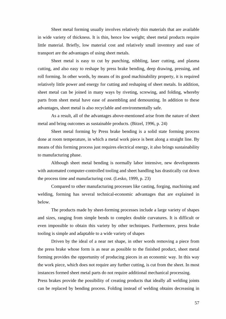
Sheet metal forming usually involves relatively thin materials that are available
in wide variety of thickness. It is thin, hence low weight; sheet metal products require
little material. Briefly, low material cost and relatively small inventory and ease of
transport are the advantages of using sheet metals.
Sheet metal is easy to cut by punching, nibbling, laser cutting, and plasma
cutting, and also easy to reshape by press brake bending, deep drawing, pressing, and
roll forming. In other words, by means of its good machinability property, it is required
relatively little power and energy for cutting and reshaping of sheet metals. In addition,
sheet metal can be joined in many ways by riveting, screwing, and folding, whereby
arts from sheet metal have ease of assembling and demounting. In addition to these
ble and environmentally safe.
As a result, all of the advantages above-mentioned arise from the nature of sheet
metal a
is a solid state forming process
done a
labor intensive, new developments
with au
. It is difficult or
even im
es not require any further cutting, is cut from the sheet. In most
instanc
ng obtains decreasing in
p
advantages, sheet metal is also recycla
nd bring outcomes as sustainable products. (Bitzel, 1996, p. 24)
Sheet metal forming by Press brake bending
t room temperature, in which a metal work piece is bent along a straight line. By
means of this forming process just requires electrical energy, it also brings sustainability
to manufacturing phase.
Although sheet metal bending is normally
tomated computer-controlled tooling and sheet handling has drastically cut down
the process time and manufacturing cost. (Lesko, 1999, p. 23)
Compared to other manufacturing processes like casting, forging, machining and
welding, forming has several technical-economic advantages that are explained in
below.
The products made by sheet-forming processes include a large variety of shapes
and sizes, ranging from simple bends to complex double curvatures
possible to obtain this variety by other techniques. Furthermore, press brake
tooling is simple and adaptable to a wide variety of shapes
Driven by the ideal of a near net shape, in other words removing a piece from
the press brake whose form is as near as possible to the finished product, sheet metal
forming provides the opportunity of producing pieces in an economic way. In this way
the work piece, which do
es formed sheet metal parts do not require additional mechanical processing.
Press brakes provide the possibility of creating products that ideally all welding joints
can be replaced by bending process. Folding instead of weldi
57

produc
etal bending, it is also possible to use the same pieces despite different
functio
way that final products in desired shape and appearance can be quickly and easily
press brakes allow high production rates by
widely being employed in almost all industrial fields. (Bitzel, 1996, p. 24)
Sheet metal process chain is described as the manufacturing process of a sheet
metal part from its design to its completion as a finished product. Producing the high-
machine technology and a productive sheet metal processing chain from the design
phase to the time the product is delivered to the costumer.
tion time. In addition, because of there is always the danger of distortion in
welding; folding instead of welding also prevents the material casualty. By means of
sheet m
ns. Thus, it is obtained the decreasing in the piece numbers and simplified
storage (Bitzel, 1996, p. 110).
Figure 3.23: The same pieces despite different functions, (Bitzel, 1996, p. 24)
Besides these advantages, the dimensional accuracy of sheet metal parts ensures
their exchangeability in assembly, and also the mechanical properties of formed very
light sheet metal parts are increased by strain hardening
Consequently, because of its economic efficiency in mass production, in such a
quality product quickly and economically is achieved by the using of fully developed
produced with relatively simple tool set, and also automated and numeric controlled
fast operation, sheet metal forming is
Figure 3.24: Sheet Metal forming process, (Bitzel, 1996, p. 16)
58
The process chain for sheet metal forming is divided into three areas that are
ideally linked the each other, such as designing, flat processing and bending.
he final form decided on is
converted into a developed view in the end of the design process. This 3D developed
view is unfolded automatically into 2D drawing by a 3D CAD system. And then this 2D
drawing is developed automatically into 3D models again by taking the available tools
and folding sequence into consideration. Thus, it possible to determine the problems
such as cross section, overlapping, or missing cutouts beforehand production. The 2D
drawing of the faultless unfolded state is passed on to the programming system for flat
processing (Bitzel, 1996, p. 16).
rged. Only
by considering the characteristic of sheet metal and the advantages afforded by modern
e design process, a functional and economically
anufactured product is obtained (Bitzel, 1996, p. 22).
with stand scratching, and toughness; that is the ability
to with
material is to reduce the sheet
thickness. This results not only in less weight, but also in reduced production times.
3.3.1.1 Designing Sheet Metal
The process chain begins with the design. Sophisticated design systems support
the designer by providing photo realistic 3D models. T
In principle, designing sheet metal is not different from other semi-finished
products such as solid stocks, metal profiles, or parts that have been cast or fo
sheet metal processing in th
m
Some characteristics and mechanical properties of sheet metal, which should be
considered in material selection and also which affect on the bendability, are plasticity;
that is the ability for metal to be permanently deformed and to hold the new shape
without breaking, elasticity; that refers the resiliency of a metal to return to its original
shape when a stress is removed after being deformed, machinability; that is the ease
with machining or cutting by machine tools, ductility; that is the ability of a material to
withstand plastic deformation without rupture, brittleness; that refers to how easily a
metal will break with little or no bending, in this way, opposite of ductility, hardness;
that is the ability of a material to
stand sudden shocks without breaking. In such a way that tough materials could
bend without breaking, on the contrary very hard materials will become brittle and
break easily (Lesko, 1999, pp. 7-8).
There are also lots of fundamental hints to be considered on sheet metal design
process. For instance, the most effective way to save
59
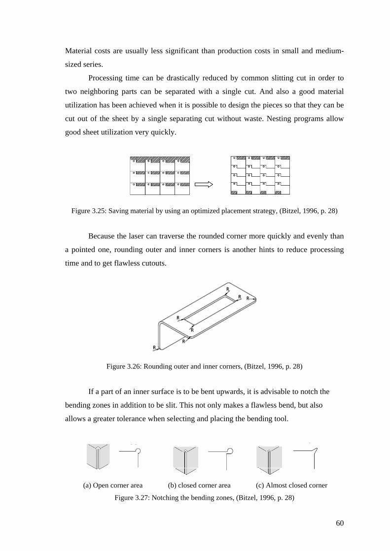
Materi
Figur
et fl
Figure 3.26: Rounding outer and inner corners, (Bitzel, 1996, p. 28)
bending zones in addition to be slit. This not only makes a flawless bend, but also
al
(a) Open corner area (b) closed corner area (c) Almost closed corner Figure 3.27: Notching the bending zones, (Bitzel, 1996, p. 28)
al costs are usually less significant than production costs in small and medium-
sized series.
Processing time can be drastically reduced by common slitting cut in order to
two neighboring parts can be separated with a single cut. And also a good material
utilization has been achieved when it is possible to design the pieces so that they can be
cut out of the sheet by a single separating cut without waste. Nesting programs allow
good sheet utilization very quickly.
e 3.25: Saving material by using an optimized placement strategy, (Bitzel, 1996, p. 28)
Because the laser can traverse the rounded corner more quickly and evenly than
a pointed one, rounding outer and inner corners is another hints to reduce processing
time and to g awless cutouts.
If a part of an inner surface is to be bent upwards, it is advisable to notch the
lows a greater tolerance when selecting and placing the bending tool.
60
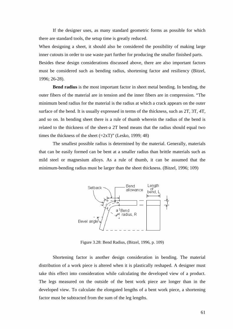
If the designer uses, as many standard geometric forms as possible for which
there are standard tools, the setup time is greatly reduced.
When designing aking large
inner cutouts in order to use waste part further for producing the sm
1996; 26-28).
Bend radius is the most important factor in sheet metal bending. In bending, the
outer fibers of the material are in tension and the inner fibers are in compression. “The
minimum bend radius for the material is the radius at which a crack appears on the outer
and so on. In b of the bend is
related to the thickness of the sheet-a 2T bend means that the radius should equal two
times t
aterial. Generally, materials
a sheet, it should also be considered the possibility of m
aller finished parts.
Besides these design considerations discussed above, there are also important factors
must be considered such as bending radius, shortening factor and resiliency (Bitzel,
surface of the bend. It is usually expressed in terms of the thickness, such as 2T, 3T, 4T,
ending sheet there is a rule of thumb wherein the radius
he thickness of the sheet (=2xT)” (Lesko, 1999; 48)
The smallest possible radius is determined by the m
that can be easily formed can be bent at a smaller radius than brittle materials such as
mild steel or magnesium alloys. As a rule of thumb, it can be assumed that the
minimum-bending radius must be larger than the sheet thickness. (Bitzel, 1996; 109)
Figure 3.28: Bend Radius, (Bitzel, 1996, p. 109)
ct.
The legs measured on the outside of the bent work piece are longer than in the
developed view. To calculate the elongated lengths of a bent work piece, a shortening
factor must be subtracted from the sum of the leg lengths.
Shortening factor is another design consideration in bending. The material
distribution of a work piece is altered when it is plastically reshaped. A designer must
take this effect into consideration while calculating the developed view of a produ
61

Angles smaller than 65° can even have a negative shortening factor. The
designer must be informed of the empirically calculated shortening factor that depends
on material thickness. (Bitzel, 1996, p. 105)
L = a+b- x whereby L= elongated length and x = shortening factor
ncy of the sheet to bend back
into its
tered. Thicker sheets are less resilient than
thinne itzel,
1996, p. 102)
Figure 3.29: Elongated length L = a+b- x, (Bitzel, 1996, p. 105)
Resiliency, in other words spring back is the tende
original shape once pressure has been removed from the punch. In practical
terms, the sheet must be bent at angle smaller than the angle desired. The more the sheet
is bent, the fewer resiliencies will be encoun
r ones; and also stronger materials less resilient than weaker materials. (B
Figure 3.30: Resiliency (spring back), (http://nsmwww.eng.ohio-state.edu/html/stamping.html)
3.3.1.2 Flat Processing (Shearing Process
)
The production phase of a work piece always begins with flat processing. The
blanks are the first pieces to be manufactured from the raw sheet, which are then folded.
The goal is to create the final form in as few steps as possible. That’s why it is
62

preferable to have the entire flat processing done on a single machine. Modern multi-
function machines offer this ability. The press brake does not come into action until flat
processing has been completed. The quality of the bent part can be improved by
straightening the blanks beforehand. By programming the bending process with the
simulation of bending results and determining the tools to be used, setup and processing
times are reduced during production. (Bitzel, 1996, p. 19)
Before a sheet metal part is formed, the work piece so-called “blank” that will be
formed into the final part is removed from sheet metal stock. Sheet metal cutting
processes includes a number of techniques. Common types of sheet metal cutting are
cutting has also become an important process, so that it is used with computer-
s consistently.
Various shearing operations shown in Figure 3.31 can be classified as blanking,
punchi
menet.umn.edu/)
ple,
oblong holes arranged in a star shape, thes
machine equipped with tool rotation. If the vents are designed as lower slits, the formed
electrical discharge machining, laser cutting, water jet and abrasive cutting. Laser
controlled equipment to cut a variety of shape
ng, and die cutting. In blanking the slug is the blank to be further processed
whereas, the slug removed from the blank is not used to form the part in punching.
Die cutting is used to produce more complex blanks that might be the final part.
This kind of shearing consists of the following operations: Perforation -punching a
number of holes in a sheet-; parting -shearing the sheet into two or more pieces-;
notching -removing pieces of various shapes from the edge-; lancing and slitting -
leaving a tab without removing any material.
Figure 3.31: Various shearing operations, (http://www.
If the construction drawing has a large number of free geometric forms with
many rounded corners and tangential crossovers, the part is manufacture with laser
beam. If the vents are designed with simple standard geometric forms, for exam
e forms could be processed with a punching
areas can be created with punching machine and appropriate tools. (Bitzel, 1996, p. 18)
63

3.3.1.3 Sheet Metal Bending
Sheet metal forming by press brake bending is a process that a metal work piece
is bent along a straight line. The major devices used for bending are presses and dies.
Sheet metal bending operations involve placing sheet metal on a die up against a back
gage to precisely locate the part. At this
gap between the punches and die until the part
time, the machine is commanded to close the
is bent into the cavity of the die (Wang
& Bourne, 1997, pp. 281-294).
Figure 3.32: Bending process phases, (Wang & Bourne, 1997, p. 290)
The most common types of sheet metal bending are discussed in below with a
comparative approach.
Air V Three-point U-die Wiping die Rotary
Figure 3.33: Special punch and dies for sheet metal bending
(http://nsmwww.eng.ohio-state.edu/html/)
Air bending, also known as free bending, is a process which a punch bends a
work p
ss tonnage. However accurate control of the punch stroke is
necessary to obtain the desired bend angle. In air bending, there is no need to change
iece without pressing it to the bottom of the die. This process requires a
relatively quite low pre
64
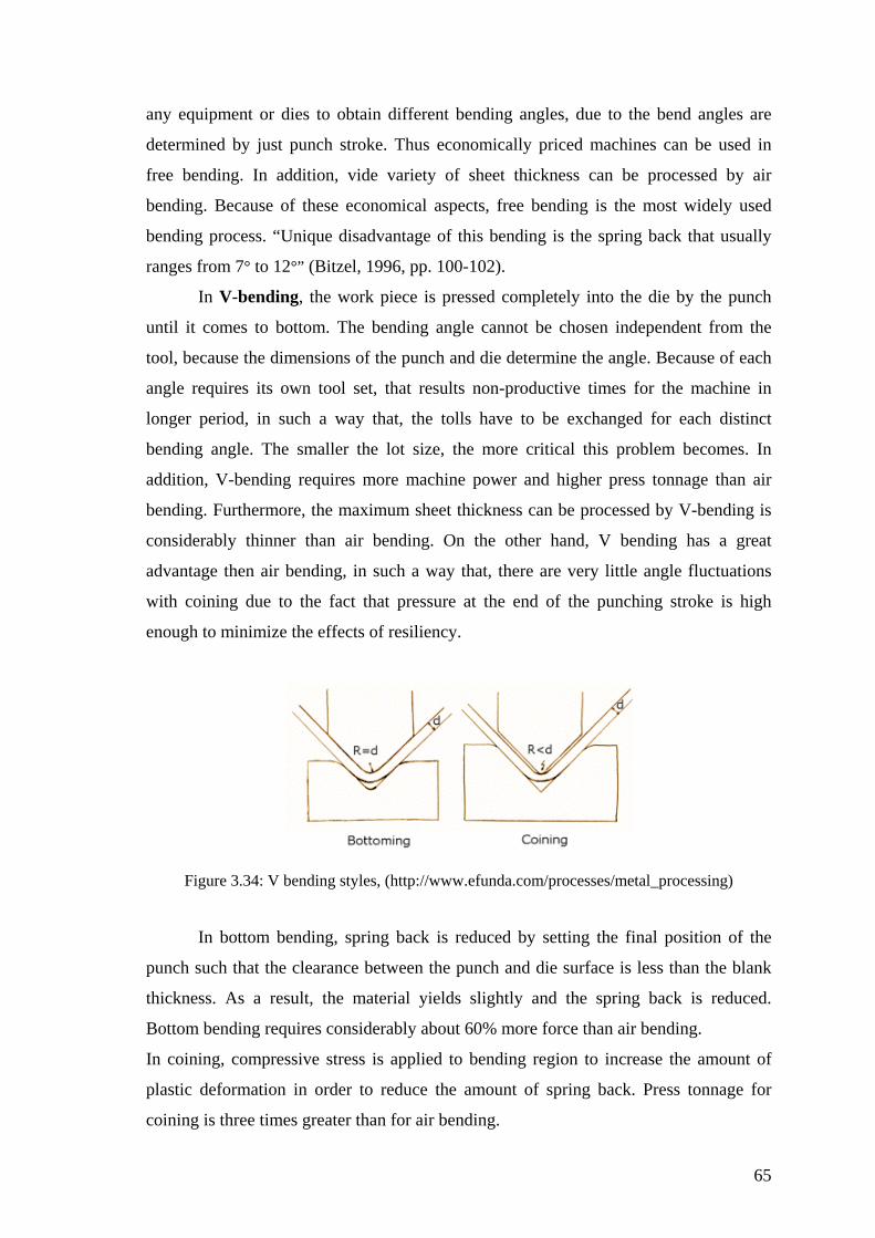
any equipment or dies to obtain different bending angles, due to the bend angles are
determined by just punch stroke. Thus economically priced machines can be used in
free bending. In addition, vide variety of sheet thickness can be processed by air
bending. Because of these economical aspects, free bending is the most widely used
ranges from 7° to 12
In V-bending, the w he die by the punch
until it comes to bottom. The bending angle cannot be chosen independent from the
tool, be
bending process. “Unique disadvantage of this bending is the spring back that usually
°” (Bitzel, 1996, pp. 100-102).
ork piece is pressed completely into t
cause the dimensions of the punch and die determine the angle. Because of each
angle requires its own tool set, that results non-productive times for the machine in
longer period, in such a way that, the tolls have to be exchanged for each distinct
bending angle. The smaller the lot size, the more critical this problem becomes. In
addition, V-bending requires more machine power and higher press tonnage than air
bending. Furthermore, the maximum sheet thickness can be processed by V-bending is
considerably thinner than air bending. On the other hand, V bending has a great
advantage then air bending, in such a way that, there are very little angle fluctuations
with coining due to the fact that pressure at the end of the punching stroke is high
enough to minimize the effects of resiliency.
Figure 3.34: V bending styles, (http://www.efunda.com/processes/metal_processing)
In bottom bending, spring back is reduced by setting the final position of the
punch such that the clearance between the punch and die surface is less than the blank
thickness. As a result, the material yields slightly and the spring back is reduced.
Bottom ending requires considerably about 60% more force than air bending.
In coining, compressive stress is applied to bending region to increase the amount of
plastic deformation in order to reduce the amount of spring back. Press tonnage for
coining is three times greater than for air bending.
b
65
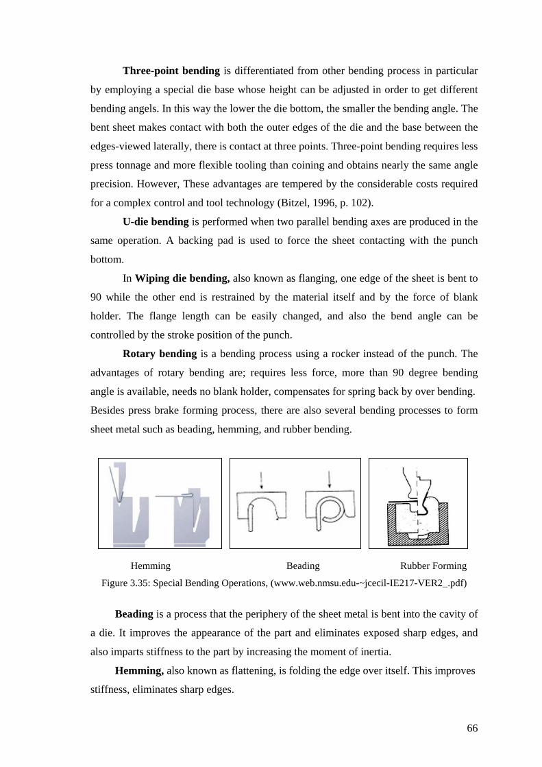
66
Three-point bending is differentiated from other bending process in particular
by employing a special die base whose height can be adjusted in order to get different
bending angels. In this way the lower the die bottom, the smaller the bending angle. The
bent sheet makes contact with both the outer edges of the die and the base between the
edges-viewed laterally, there is contact at three points. Three-point bending requires less
press tonnage and more flexible tooling than coining and obtains nearly the same angle
preci ired
for a complex control and tool technology (Bitzel, 1996, p. 102).
bent to
the sheet metal is bent into the cavity of
a die. I
stiffness, eliminates sharp edges.
sion. However, These advantages are tempered by the considerable costs requ
U-die bending is performed when two parallel bending axes are produced in the
same operation. A backing pad is used to force the sheet contacting with the punch
bottom.
In Wiping die bending, also known as flanging, one edge of the sheet is
90 while the other end is restrained by the material itself and by the force of blank
holder. The flange length can be easily changed, and also the bend angle can be
controlled by the stroke position of the punch.
Rotary bending is a bending process using a rocker instead of the punch. The
advantages of rotary bending are; requires less force, more than 90 degree bending
angle is available, needs no blank holder, compensates for spring back by over bending.
Besides press brake forming process, there are also several bending processes to form
sheet metal such as beading, hemming, and rubber bending.
Hemming Beading Rubber Forming
Figure 3.35: Special Bending Operations, (www.web.nmsu.edu-~jcecil-IE217-VER2_.pdf)
Beading is a process that the periphery of
t improves the appearance of the part and eliminates exposed sharp edges, and
also imparts stiffness to the part by increasing the moment of inertia.
Hemming, also known as flattening, is folding the edge over itself. This improves
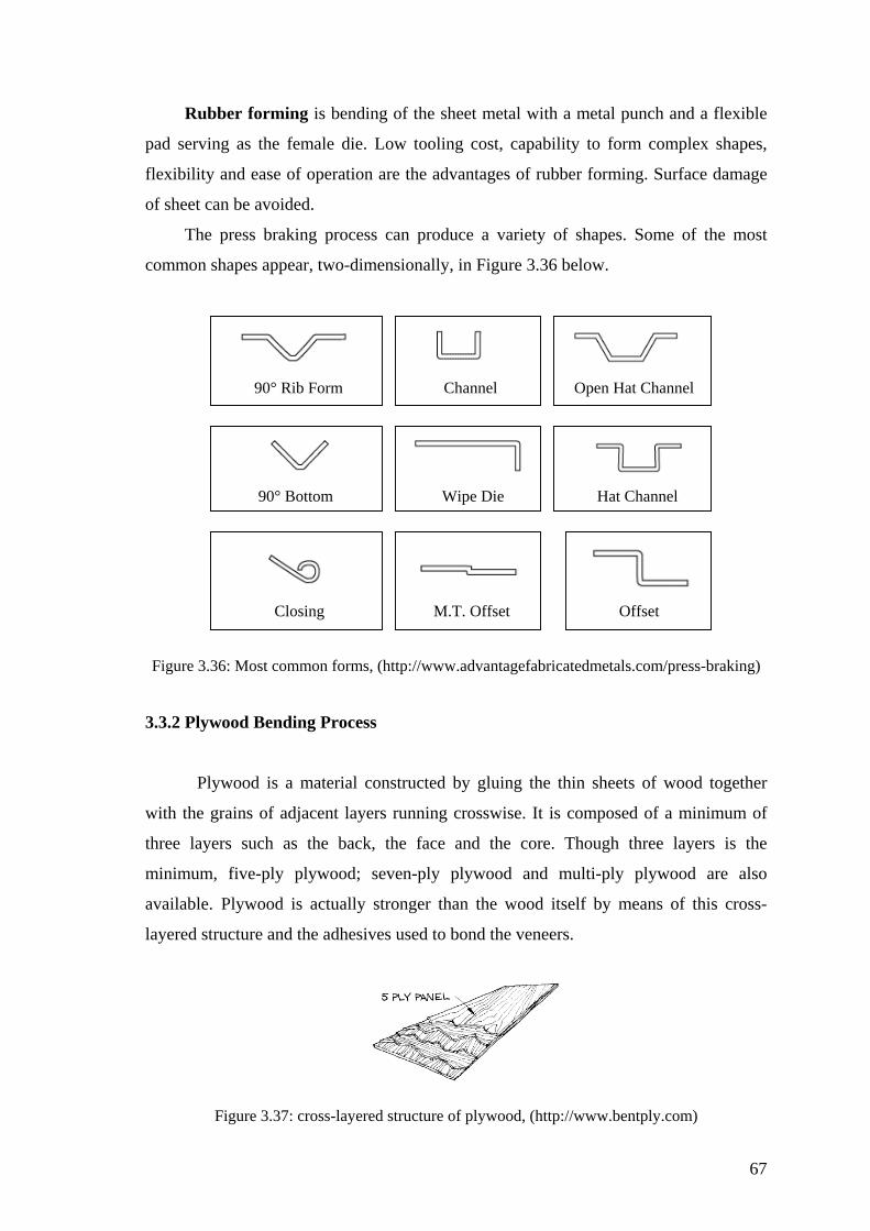
Rubber forming is bending of the sheet metal with a metal punch and a flexible
pad serving as the female die. Low tooling cost, capability to form complex shapes,
exibility and ease of operation are the advantages of rubber forming. Surface damage
of sheet can be avoided.
The press braking process can produce a variety of shapes. Some of the most
common shapes appear, two-dimensionally, in Figure 3.36 below.
fl
90° Rib Form Channel Open Hat Channel
90° Bottom Wipe Die Hat Channel
Closing M.T. Offset Offset
Figure 3.36: Most common forms, (http://www.advantagefabricatedmetals.com/press-braking)
3.3.2
Plywood is a material constructed by gluing the thin sheets of wood together
with the grains of adjacent layers running crosswise. It is composed of a minimum of
such as the ba face and the core. Though three layers is the
also
vailable. Plywood is actually stronger than the wood itself by means of this cross-
layered structure and the adhesives used to bond the veneers.
Figure 3.37: cross-layered structure of plywood, (http://www.bentply.com)
Plywood Bending Process
three layers ck, the
minimum, five-ply plywood; seven-ply plywood and multi-ply plywood are
a
67
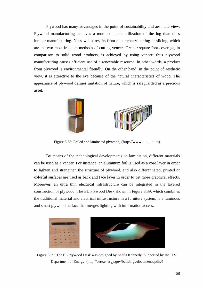
Plywood has many advantages in the point of sustainability and aesthetic view.
Plywood manufacturing achieves a more complete utilization of the log than does
st results from either rotary cutting or slicing, which
re the two most frequent methods of cutting veneer. Greater square foot coverage, in
compa
art plywood surface that merges lighting with information access.
lumber manufacturing. No sawdu
a
rison to solid wood products, is achieved by using veneer; thus plywood
manufacturing causes efficient use of a renewable resource. In other words, a product
from plywood is environmental friendly. On the other hand, in the point of aesthetic
view, it is attractive to the eye because of the natural characteristics of wood. The
appearance of plywood defines imitation of nature, which is safeguarded as a precious
asset.
Figure 3.38: Foiled and laminated plywood, (http://www.cinal.com)
By means of the technological developments on lamination, different materials
can be used as a veneer. For instance, an aluminum foil is used as a core layer in order
to lighten and strengthen the structure of plywood, and also differentiated, printed or
colorful surfaces are used as back and face layer in order to get more graphical effects.
Moreover, an ultra thin electrical infrastructure can be integrated in the layered
construction of plywood. The EL Plywood Desk shown in Figure 3.39, which combines
the traditional material and electrical infrastructure in a furniture system, is a luminous
and sm
Figure 3.39 y the U.S.
Department of Energy, (http://eere.energy.gov/buildings/documents/pdfs/)
: The EL Plywood Desk was designed by Sheila Kennedy, Supported b
68
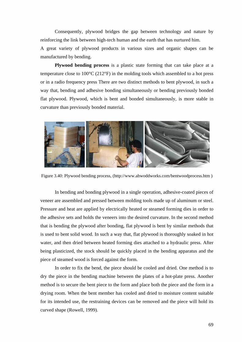
Consequently, plywood bridges the gap between technology and nature by
reinforcing the link between high-tech human and the earth that has nurtured him.
A great variety of plywood products in various sizes and organic shapes can be
manufactured by bending.
Plywood bending process is a plastic state forming that can take place at a
temperature close to 100°C (212°F) in the molding tools which assembled to a hot press
or in a radio frequency press There are two distinct methods to bent plywood, in such a
way that, bending and adhesive bonding simultaneously or bending previously bonded
flat plywood. Plywood, which is bent and bonded simultaneously, is more stable in
curvature than previously bonded material.
Figure 3.40: Plywood bending process, (http://www.ahwoddworks.com/bentwoodprocess.htm )
ing plywood in a single operation, adhesive-coated pieces of
veneer
After
being plasticized, the stock should be quickly placed in the bending apparatus and the
piece of steamed wood is forced against the form.
In order to fix the bend, the piece should be cooled and dried. One method is to
dry the piece in the bending machine between the plates of a hot-plate press. Another
method is to secure the bent piece to the form and place both the piece and the form in a
drying room. When the bent member has cooled and dried to moisture content suitable
r its intended use, the restraining devices can be removed and the piece will hold its
In bending and bond
are assembled and pressed between molding tools made up of aluminum or steel.
Pressure and heat are applied by electrically heated or steamed forming dies in order to
the adhesive sets and holds the veneers into the desired curvature. In the second method
that is bending the plywood after bonding, flat plywood is bent by similar methods that
is used to bent solid wood. In such a way that, flat plywood is thoroughly soaked in hot
water, and then dried between heated forming dies attached to a hydraulic press.
fo
curved shape (Rowell, 1999).
69
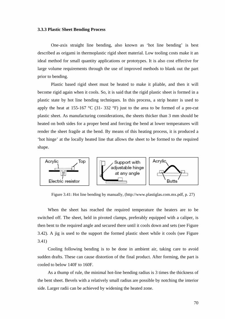
3.3.3 Plastic Sheet Bending Process
is process, a strip heater is used to
apply t
W
s a thump of rule, the minimal hot-line bending radius is 3 times the thickness of
the bent sheet. Bevels with a relatively small radius are possible by notching the interior
side. Larger radii can be achieved by widening the heated zone.
One-axis straight line bending, also known as ‘hot line bending’ is best
described as origami in thermoplastic rigid sheet material. Low tooling costs make it an
ideal method for small quantity applications or prototypes. It is also cost effective for
large volume requirements through the use of improved methods to blank out the part
prior to bending.
Plastic based rigid sheet must be heated to make it pliable, and then it will
become rigid again when it cools. So, it is said that the rigid plastic sheet is formed in a
plastic state by hot line bending techniques. In th
he heat at 155-167 °C (31- 332 °F) just to the area to be formed of a pre-cut
plastic sheet. As manufacturing considerations, the sheets thicker than 3 mm should be
heated on both sides for a proper bend and forcing the bend at lower temperatures will
render the sheet fragile at the bend. By means of this heating process, it is produced a
‘hot hinge’ at the locally heated line that allows the sheet to be formed to the required
shape.
Figure 3.41: Hot line bending by manually, (http://www.plastiglas.com.mx.pdf, p. 27)
hen the sheet has reached the required temperature the heaters are to be
switched off. The sheet, held in pivoted clamps, preferably equipped with a caliper, is
then bent to the required angle and secured there until it cools down and sets (see Figure
3.42). A jig is used to the support the formed plastic sheet while it cools (see Figure
3.41)
Cooling following bending is to be done in ambient air, taking care to avoid
sudden drafts. These can cause distortion of the final product. After forming, the part is
cooled to below 140F to 160F.
A
70

Figure 3.42: Hot line bending with bending machine, (www.plastiglas.com.mx.pdf, p. 26)
The line that will be scored on the polypropylene sheets are formed by the
techniques known as ‘hot stamping’, which is similar to scoring of paper or cardboard
(see Section 3.3.4). The stamping process of polypropylene sheets does not require
heated material, but heated tools for working temperatures at 100-130°C (212-266°F).
(Palsun technical manual, 2004, pp. 23-26)
3.3.4 Paper Sheet Folding Process
Scoring prior to folding reduces the stress ness that folding puts on paper, it may
be scored before being folded. Scoring also helps to reduce the risk of crocking, and for
some types of board scoring is even necessary to create a clean, well-defined fold.
Whil
such a way, a rounded rule pressing the paper into a channel. The width of the rule and
channe
any types of board are used. Because if the weight of the paper increases so does its
tendency to crack.
e three or several types of scoring devices, all work on a common principle. In
l will depend on the thickness of the paper. There is a thump of rule that the rule
should never be thinner than the paper.
Scoring should be considered if a job requires multiple folds, if a thick paper or
71

Figure 3.43: The principle of scoring, (Withers, 2002, p. 10).
Folding
Standard folding machines can make four separate folds in one go. Furthermore,
with ad
t the same time as they fold. A successful fold is determined in two
ways; fold quality and fold strength. The quality of the fold refers to its appearance,
while the strength is measured by how many times a piece of paper can be folded back
and forth before breaking.
ditional folding machine extensions, the number of folds that can be completed
automatically is considerable. In addition, there are folding machines that can score,
perforate and glue a
(a) (b) (c)
Figure 3.44: Working principle of ‘Buckler’ Folding Machine, (Withers, 2002, p. 8)
Figure 3.45: Working principle of ‘Knife’ Folding Machine, (Withers, 2002, p. 8)
72
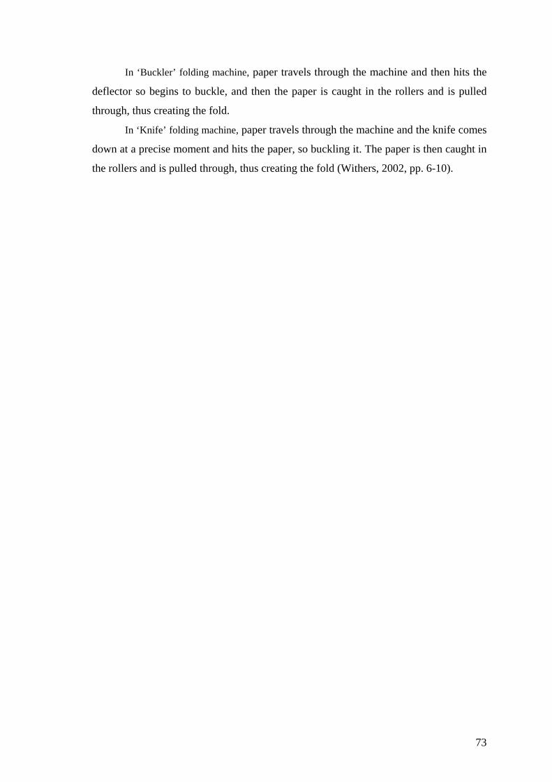
In ‘Buckler’ folding machine, paper travels through the machine and then hits the
deflector so begins to buckle, and then the paper is caught in the rollers and is pulled
through, thus creating the fold.
In ‘Knife’ folding machine, paper travels through the machine and the knife comes
down at a precise moment and hits the paper, so buckling it. The paper is then caught in
the rollers and is pulled through, thus creating the fold (Withers, 2002, pp. 6-10).
73

CHAPTER 4
CASE STUDIES
In this chapter, it is purposed to attain a synthesis by considering the analysis
in previous chapters, which are on origami design and origamic structured industrial
products. With this intention, the industrial products designed by my own throughout
my industrial design education have been discussed in detail in order to throw light
on how these products were structured by considering origami design.
“Every form described in two ways: from the point of view of what it is, and
from the point of view of what it does. What it is sometimes called the formal
description. What it does, when it is put in contact with other things, is sometimes
called the functional description” (Alexander, 1964, p. 89).
By regarding this quoting from influential design methodologist C. Alexander,
the products have been described as either formal or functional in order to evaluate
the appropriateness of their forms and contexts.
All the product proposals have been designed to solve the certain problems
defined in below by considering the unity, modularity, and simplicity concepts. The
forms of all of them have been constituted by using symmetry, isometry and
repetition principles that had been discussed in Chapter Two. Furthermore, all the
proposals have been made from sheet materials and formed by considering one-axis
bending process that had been discussed in Chapter Three.
4.1 Base
Figure 4.1: Product Proposal 1: Base
74
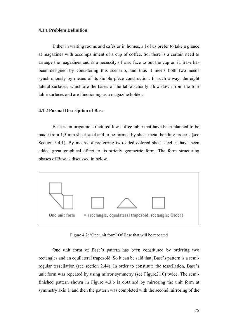
4.1.1 Problem Definition
Either in waiting rooms and cafés or in homes, all of us prefer to take a glance
at magazines with accompaniment of a cup of coffee. So, there is a certain need to
arrange the magazines and is a necessity of a surface to put the cup on it. Base has
been designed by considering this scenario, and thus it meets both two needs
synchronously by means of its simple piece construction. In such a way, the eight
lateral surfaces, which are the bases of the table actually, flow down from the four
table surfaces and are functioning as a magazine holder.
4.1.2 Formal Description of Base
Base is an origamic structured low coffee table that have been planned to be
made from 1,5 mm sheet steel and to be formed by sheet metal bending process (see
Section 3.4.1). By means of preferring two-sided colored sheet steel, it have been
added great graphical effect to its strictly geometric form. The form structuring
phases of Base is discussed in below.
Figure 4.2: ‘One unit form’ Of Base that will be repeated
One unit form of Base’s pattern has been constituted by ordering two
rectangles and an equilateral trapezoid. So it can be said that, Base’s pattern is a semi-
regular tessellation (see section 2.44). In order to constitute the tessellation, Base’s
unit form was repeated by using mirror symmetry (see Figure2.10) twice. The semi-
finished pattern shown in Figure 4.3.b is obtained by mirroring the unit form at
symmetry axis 1, and then the pattern was completed with the second mirroring of the
75

semi-finished pattern at symmetry axis 2. On the basis of the symmetry groups that
were discussed in Section 2.3, it can be said that Base is labeled with the ‘cm’
symmetry group (see. Figure 2.14).
Figure 4.3: Constituting the pattern by considering symmetry principle
Figure 4.4: Crease pattern of Base
The crease pattern of Base shown in Figure 4.4 was determined in order to
clarify how to fold each vertex. Base has been formed by considering this
combination of ‘valley’ and ‘mountain’ folds (see Section 2.4.1). The four bases of
76

Base have been formed by the valley folds illustrated with the doted lines. This
creased pattern had been used to determine the bending sequence.
Figure 4.5: Bending Sequence Of Base
77

The certain shape of ‘blank’ (see Section 3.3.1.2) has been designed by
considering ‘the large inner cutouts’ (see Section 3.3.1.1). In figure illustrated above,
‘a’ represents the flat processing and the line illustrated in red color represent the
slitting (see Figure 3.31); ‘b’, ‘c’, ‘d’, ‘g’ and ‘h’ represents V-die bending process
with 97 degree; ‘e’ and ‘f’ represents V-die bending process with 14 degree.
Figure 4.6: Technical Drawings Of Base (measures: mm, scale: 1/20)
78
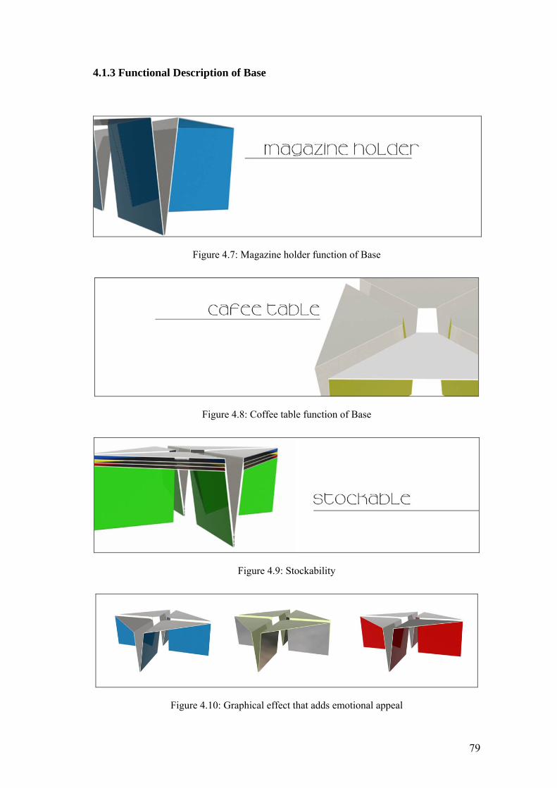
4.1.3 Functional Description of Base
Figure 4.7: Magazine holder function of Base
Figure 4.8: Coffee table function of Base
Figure 4.9: Stockability
Figure 4.10: Graphical effect that adds emotional appeal
79

Figure 4.11: Perspective Preview 1 of Base
Figure 4.12: Perspective Preview 2 of Base
80

4.2 Pure
Figure 4.13: Product Proposal 2: Pure
4.2.1 Problem Definition
Pure has been designed to solve the ‘visual mess’ problem. Herein the term
‘visual mess’ has been used to define the untidiness that results from the ‘objects’ on
the table surface. It has been indented to solve this problem in an unusual way by
creating an area for stocking on the surface of the Pure. In such a way that, when four
units of Pure are brought together at the same point, a concave volume in 20 mm
depth takes shape by means of its concave lateral surface bended with an obtuse
angle. In the event of it is used as a single unit at the corner of the room, because of
its two vertexes contact with the wall, it is also possible to obtain the concave
stocking volume, but in a quarter. Consequently, Pure has been designed as a hobby
table for adults, and also as a play table for their children or as a low table for who
favors tidiness. By means of its simple structure, Pure causes to manufacturer to earn
in manufacturing cost, and also it has ease of assembly and maintenance. Besides, it
also wins in transporting cost by means of its impressive stockability. Moreover, its
simple structure enables it to be mass-produced by automatic CNC press brake
bending. Consequently, besides Pure satisfies the certain needs defined above, it is
also solve the cost problem.
4.2.2 Formal Description Of Pure
Pure is an origamic structured table that have been planned to be made from
1,5 mm sheet steel and to be formed by press brake bending. One unit form of Pure
81

shown in Figure 4.14 has been based on a quarter of circle. Thus the completed form
of Pure shown in Figure 4.14.b has been constitute by considering four fold symmetry
(see Figure 2.11.c).
(a) One Unit Form (b) Four Unit Forms
Figure 4.14: Unit Forms of Pure
Figure 4.15: Crease pattern of Pure
82
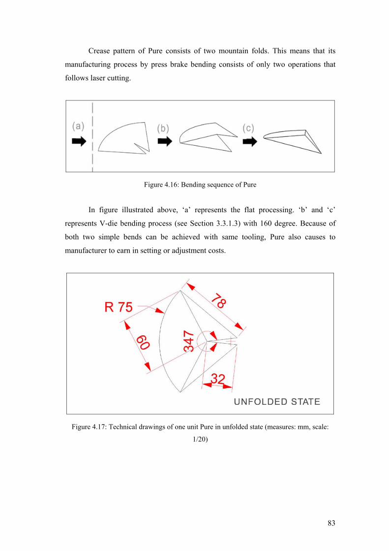
Crease pattern of Pure consists of two mountain folds. This means that its
manufacturing process by press brake bending consists of only two operations that
follows laser cutting.
Figure 4.16: Bending sequence of Pure
In figure illustrated above, ‘a’ represents the flat processing. ‘b’ and ‘c’
represents V-die bending process (see Section 3.3.1.3) with 160 degree. Because of
both two simple bends can be achieved with same tooling, Pure also causes to
manufacturer to earn in setting or adjustment costs.
Figure 4.17: Technical drawings of one unit Pure in unfolded state (measures: mm, scale:
1/20)
83

Figure 4.18: Technical Drawings Of Pure in folded state (measures: mm, scale: 1/20)
84
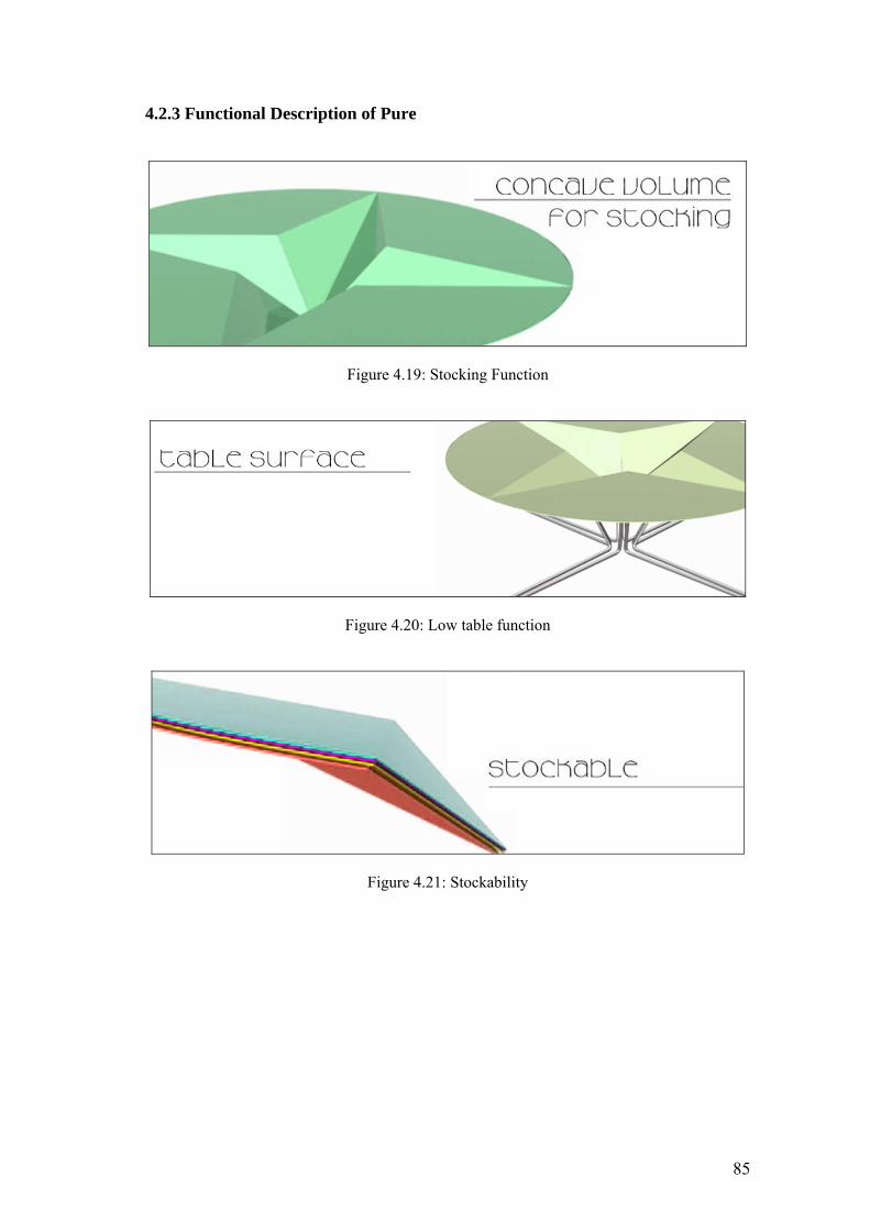
4.2.3 Functional Description of Pure
Figure 4.19: Stocking Function
Figure 4.20: Low table function
Figure 4.21: Stockability
85
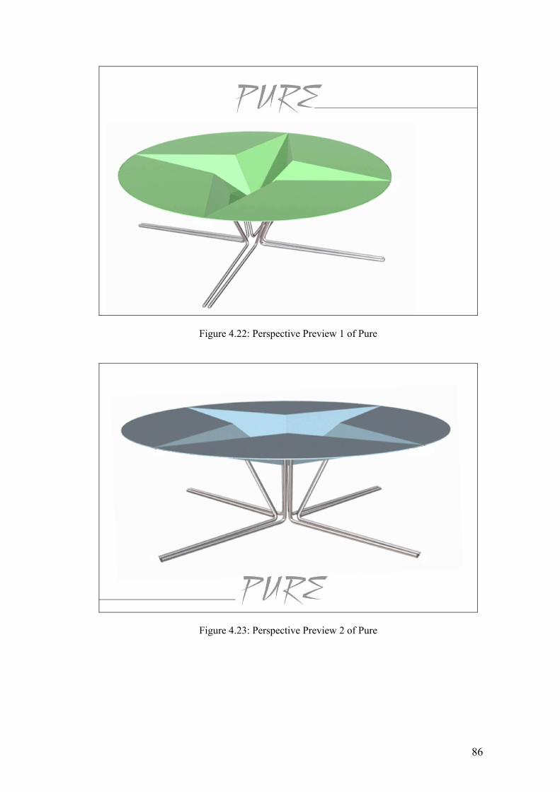
Figure 4.22: Perspective Preview 1 of Pure
Figure 4.23: Perspective Preview 2 of Pure
86

4.3 Leaf
Figure 4.24: Product Proposal 3: Leaf
4.3.1 Problem Definition
Leaf is the result of analyzing the bare essentials of common working space,
people and the objects within and proposes a synthesis of open office system solution.
It intends to satisfy the staff by enabling the team working whereas creating a
personal space at the same time. In such a way it uses the transition between objects
to redefine the working space by unifying a desk surface and a storage system into a
one plane. So, Leaf brings in an evolutionary solution for common working space by
creating its own microenvironment. In other words, instead of merely supplementing
the office landscape, Leaf innovate it.
4.3.2 Formal Description Of Leaf
One Leaf unit is a structured by considering the ‘biomimetic folding patterns’
that had been discussed in detail in Section 2.5.1.2. It consists of a corrugated surface
of alternating mountain and valley folds, meeting the midrib at an angle 60 degree.
(see Figure 4.25.a).
The tripled pattern shown in Figure 4.25.b is obtained by applying the three-
fold rotational symmetry (see Figure 2.11). This structure has a leaf-out pattern (see
Figure 2.37.a), because it is directed away from the center of the polygon.
The patterns shown in Figure 4.25.c, d, f, g are derived by considering isometries (see
Figure 2.13). The pattern shown in Figure 4.25.e is constituted by repeating the
pattern shown in Figure 4.25.d at the point ‘x’.
87
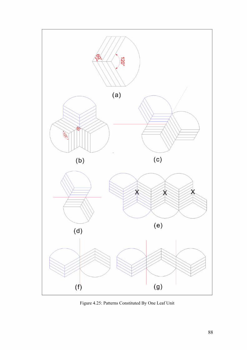
Figure 4.25: Patterns Constituted By One Leaf Unit
88

Figure 4.26: Crease pattern of one Leaf unit
The corrugated storage surfaces of Leaf are formed by alternating four
mountain folds and four valley folds. The bending sequence of one unit leaf is
determined by the crease pattern shown in Figure 4.26.
In Figure 4.27, (a) represents flat processing; (b) and (c) represents V-die
bending at angle 135 ; (d), (e), (f), and (g) reprsents V-die bending at angle 90.
The lateral surfaces that flow down from the desk surface are bend with
process (b) and (c ), and it separates the working space and storage space. Other
corrugated lateral surfaces complete the storage system.
89

Figure 4.27: Bending Sequence Of One Leaf Unit
90
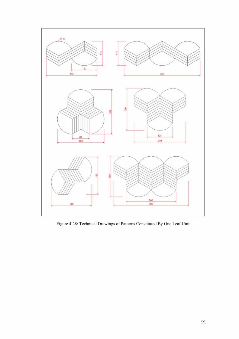
Figure 4.28: Technical Drawings of Patterns Constituted By One Leaf Unit
91

Figure 4.29: Technical Drawings Of one Leaf unit (measures: mm, scale: 1/20)
92

4.3.3 Functional Description Of Leaf
Figure 4.30: Stockability
Figure 4.31: Multipurpose of Leaf unit
Figure 4.32: Perspective Previews of Three Leaf Units (first alternative)
93

Figure 4.33: Perspective Previews of Two Leaf Units (first alternative)
Figure 4.34: Perspective Previews of Two Leaf Units (second alternative)
Figure 4.35: Perspective Previews of Three Leaf Units (second alternative)
94
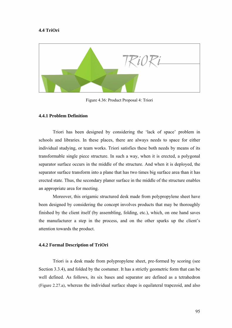
4.4 TriOri
Figure 4.36: Product Proposal 4: Triori
4.4.1 Problem Definition
Triori has been designed by considering the ‘lack of space’ problem in
schools and libraries. In these places, there are always needs to space for either
individual studying, or team works. Triori satisfies these both needs by means of its
transformable single piece structure. In such a way, when it is erected, a polygonal
separator surface occurs in the middle of the structure. And when it is deployed, the
separator surface transform into a plane that has two times big surface area than it has
erected state. Thus, the secondary planer surface in the middle of the structure enables
an appropriate area for meeting.
Moreover, this origamic structured desk made from polypropylene sheet have
been designed by considering the concept involves products that may be thoroughly
finished by the client itself (by assembling, folding, etc.), which, on one hand saves
the manufacturer a step in the process, and on the other sparks up the client’s
attention towards the product.
4.4.2 Formal Description of TriOri
Triori is a desk made from polypropylene sheet, pre-formed by scoring (see
Section 3.3.4), and folded by the costumer. It has a strictly geometric form that can be
well defined. As follows, its six bases and separator are defined as a tetrahedron
(Figure 2.27.a), whereas the individual surface shape is equilateral trapezoid, and also
95
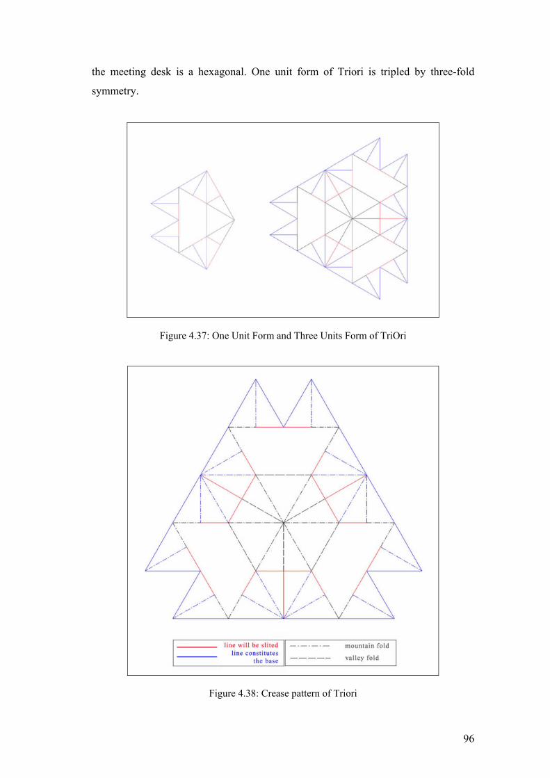
the meeting desk is a hexagonal. One unit form of Triori is tripled by three-fold
symmetry.
Figure 4.37: One Unit Form and Three Units Form of TriOri
Figure 4.38: Crease pattern of Triori
96

Figure 4.39: Technical Drawings Of TriOri (measures: mm, scale: 1/20)
97

4.4.3 Functional Description Of TriOri
Figure 4.40: Multipurpose of Triori in erected state
Figure 4.41: Multipurpose of Triori in unerected state
Figure 4.42: Flat packaging of Triori
98

Figure 4.43: Perspective Preview 1 of TriOri
Figure 4.44: Perspective Preview 2 of TriOri
99

4.5 ModulOri
Figure 4.45: Product Proposal 5: Modulori
4.5.1 Problem Definition
Modulorı is a working desk fabricated from sheet steel by bending process.
The design adds to the strength of the material; and also the shape itself solves
functional and structural issues. With its single piece construction and its continuous
surface, the spaces for writing, shelving and separating spontaneously take shape.
Tubular cd and dossier holder could be assembled to the small holes on the shelf
surface. Pencil case and also a vase can be hanged for obtaining friendlier
environment.
4.5.2 Formal Description of ModulOri
Figure 4.46: Crease Pattern Of ModulOri
100

Figure 4.47: Bending sequence of ModulOri
Figure 4.48: Technical Drawings of One unit ModulOri in unfolded state
101
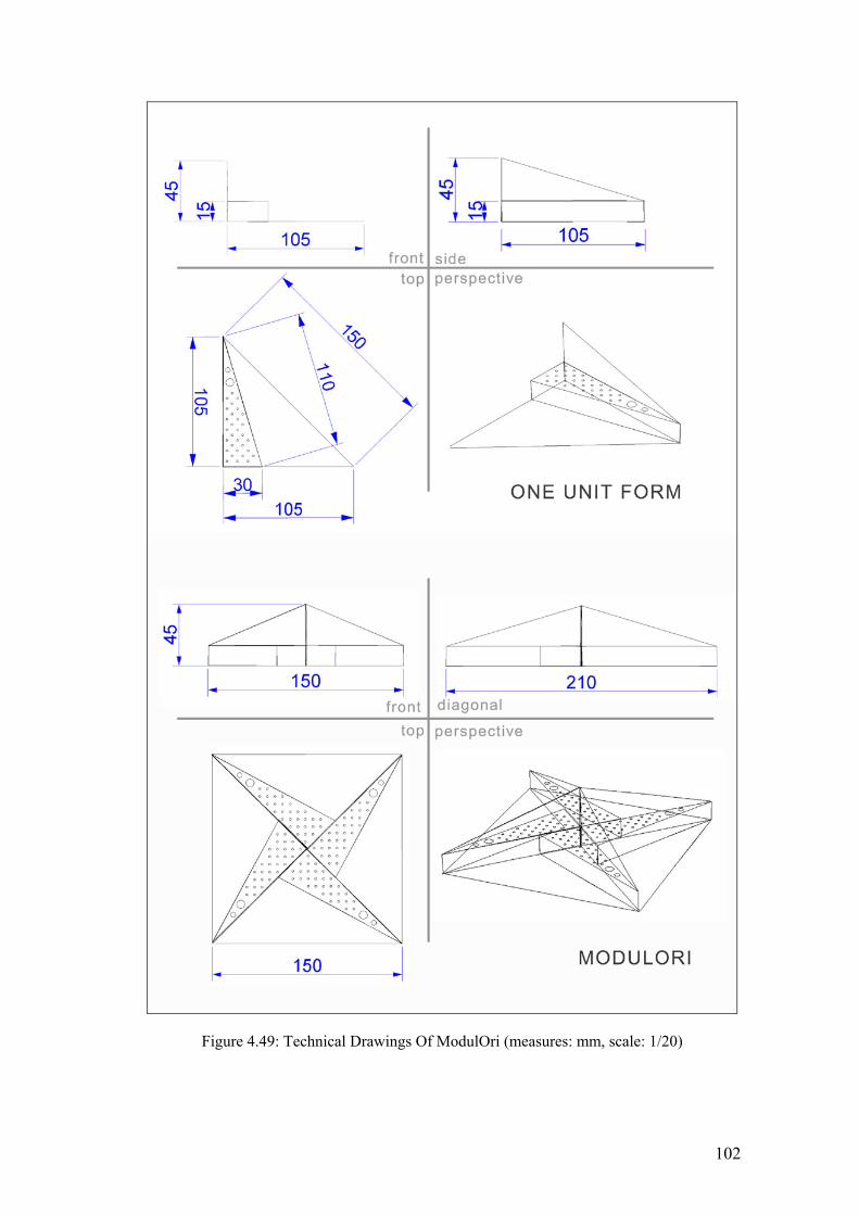
Figure 4.49: Technical Drawings Of ModulOri (measures: mm, scale: 1/20)
102

4.5.3 Functional Description of ModulOri
Figure 4.50: Multipurpose of ModulOri
Figure 4.51: Four Units Form Of ModulOri (first alternative)
Figure 4.52: Four Units Form Of ModulOri (second alternative)
103
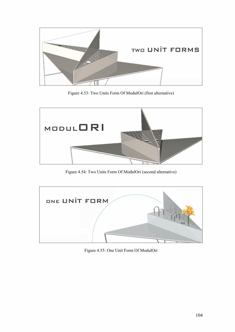
Figure 4.53: Two Units Form Of ModulOri (first alternative)
Figure 4.54: Two Units Form Of ModulOri (second alternative)
Figure 4.55: One Unit Form Of ModulOri
104

Figure 4.56: Perspective Previews of ModulOri
4.6 WindRose
Figure 4.57: Product Proposal 6: Windrose
4.6.1 Problem Definition
Windrose is a working desk fabricated from sheet steel by bending process.
The design adds to the strength of the material; and also the shape itself solves
functional and structural issues. With its single piece construction and its continuous
surface, the spaces for writing, shelving and separating spontaneously take shape.
105

4.6.2 Formal Description of Windrose
Figure 4.58: Crease Pattern Of Windrose
Figure 4.59: Bending sequence of Windrose
Figure 4.60: Technical Drawings of One unit Windrose in unfolded state
106

Figure 4.61: Technical Drawings of Windrose
107
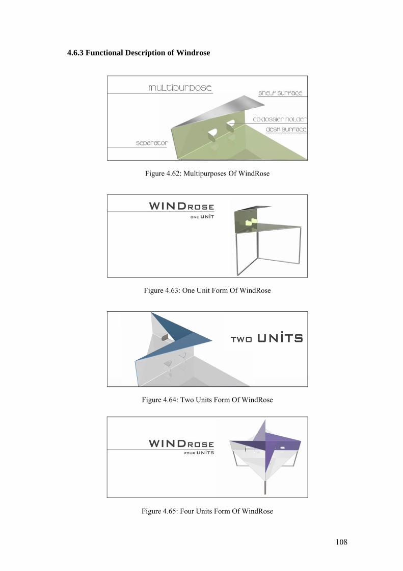
4.6.3 Functional Description of Windrose
Figure 4.62: Multipurposes Of WindRose
Figure 4.63: One Unit Form Of WindRose
Figure 4.64: Two Units Form Of WindRose
Figure 4.65: Four Units Form Of WindRose
108

Figure 4.66: Perspective Previews of WindRose
4.7 Radius
Figure 4.67: Radius Office Systems, Delta Office Systems Design Competition 2003:
Honorable Mention, designed by Nergiz Yiğit, 2003
109

4.7.1 Problem Definition
Radius is a open office system fabricated from plywood by single plywood
bending process (see Section 3.3.2.). The design adds to the strength of the material;
and also the shape itself solves functional and structural issues. With its single piece
construction and its continuous surface, the spaces for writing, shelving and
separating spontaneously take shape.
4.7.2 Formal Description of Radius
Figure 4.68: Bending of Radius
Figure 4.69: Technical Drawings of Radius
4.7.3 Functional Description of Radius
Tubular cd and dossier holder could be assembled to the small holes on the
lateral shelf surface. Pencil case or a vase can be hanged for obtaining friendlier
110
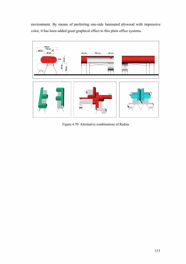
environment. By means of preferring one-side laminated plywood with impressive
color, it has been added great graphical effect to this plain office systems.
Figure 4.70: Alternative combinations of Radius
111
CHAPTER 5
CONCLUSION
The abstract forms given to sheets by applying straight, curved or combination
of these folds give way to amazing and motivating results. The products, which are
originated by using this method, are rich in design as well as function, and also they
have added value of a low production cost with the use of conventional technology.
Moreover, the nature of the material, a flat sheet is sufficiently rigid to structure
the work piece, however flexible enough to allow it to bend easily. By means of this
characteristic, origamic-structured products give way a low cost, functional and
aesthetic alternative for small and medium companies to develop high quality products.
Using simplified solutions as well as economical manufacturing processes, which do
not rely on high investments, will lead to producing internationally competitive
products through the design of new forms. On one hand, the concept about the product
that thoroughly finished by the client itself saves the manufacturer a step in the process,
and on the other hand these products spark up the client’s attention towards the product.
Besides, origamic-structured products have a single piece, simple, light and mostly free
standing construction, which is produced by simple bending operations. Thus these
products are easy to manufacture, easy to maintain and easy to construct (because
mostly they need no joints owing to their single piece construction from mono-
material). Moreover, they have ease of functioning, and also have multifunction. In the
event of origamic-structured products are made from thin sheets, by means of the
elasticity of these materials, the products are self-lockable or flat foldable, consequently
flat packable. In the case of the products are made from thick sheets, it is also possible
to design it stackable. These characteristics bring about the ease of transportation and
packaging.
If all of these characteristics and its form are evaluated by considering good
design principles, it is clearly perceived that, nearly all of these principles have been
applied to origamic-structured product. In such a way, it enhances the quality of the user
experiences. Real enhancement often can be achieved through designing and
implementing small, evolutionary adaptations. The important consideration is that any
enhancement must be related to the whole concept and process. From the this point of
view, the perforating strategy on sheet material forming makes the rigid sheet material
112
easy to bend by hand, or the products designed by considering the springy effect of thin
sheets are self locked by hand. The consumer buys such products in a flat packing state,
and then built it oneself. Thus the assembly is converted to an interactive event, and the
consumer is transformed into a designer, who forms the objects.
It is honest, because it is comprehensible and self-confident. It does not appear
more than it does, and it expresses the material, which it was created from. In other
words it is honest, because its form and its context are compromised.
It is aesthetic. If it is considered that an aesthetic appeal is a cultural construct,
there is no doubt that an origamic-structured product is a cultural construct, which is
constituted by mediating with Western materials and Eastern traditional culture.
Besides, the aesthetic experience refers to the feelings of pleasure that result from an
interaction with an artifact. Aesthetics involve the psychological and physiological
effects of line, shape, color, texture, tone, composition, context, and etc. Because of the
origamic-structured product is constituted by considering geometry, order, and
polygonal shapes, the aesthetic of this product has a universal meaning. Moreover, the
integrity and harmony of the whole are spontaneously achieved in the aesthetic of the
origamic-structured product. Especially in the event of considering the modular origami
design, it is possible to achieve impressive graphical effects by using two sides colored,
printed or laminated sheet materials.
It is innovative. Innovation involves a fashioning of existing materials, methods
and processes into new or adapted forms to meet the needs of a changing environment.
Innovation often becomes confused with originality that is genuinely new, radical, and
revolutionary. Innovation is more evolutionary. In this context, thanks to the
experimental studies on plywood and plastic sheets, the material itself is converted to an
innovation, and also by means of the developments on laminating technology,
especially plywood products gains added value in the context of emotional appeal. On
the other hand, although the sheet metal is traditional material, by means of the
technological development on tooling, unexpected forms are achieved by using a
traditional material.
Its form follows its functions, in such a way that, its form is the resolution of its
function, and it displays its logical structure.
It is minimal. In designing the origamic-structured product, the ‘unimportant’ is
omited in order to emphasize the ‘important’. This product is characterized by
simplicity that is governed by order and clarity, and also elegance and spare use of
113
detail (because the small details often ruin the potentiality of good design by disturbing
the wholeness). The origamic-structured product itself minimal because it is designed
by considering origami design, which has the minimalism concept in itself. This
minimalism results from the abstraction concept. Furthermore it is minimal in material
and also packaging. In addition, by means of the technological development on CNC
machinery and tooling technology, especially the whole sheet metal manufacturing
process can be fully automated. So, in the event of the product produced by automated
press brake bending, it is minimal in waste of time and energy, and eventually it is
maximal in productivity, thus it is minimal in cost.
It is sustainable, because it fulfills the necessity of sustainable design either in
regarding the necessities on material and construction, or regarding the necessities on
functioning such as minimization of joints, flat packing, ease of maintaining,
monomaterial, lightness, simplicity, and multipurpose.
When the origamic-structured industrial products are evaluated by in the point of
‘integrity’, which is the most important criteria to judge a design, there is no doubt that
these products inevitably has integrity in material, integrity in form, integrity in
manufacturing and integrity in functioning. By means of these integrities, the
appearance of an origamic-structured product is integrated into a pleasant whole.
Furthermore in tooling, production, packaging and transportation, it is low in cost and it
has ease of maintenance. Moreover, in the point of ‘utility’, its each feature is shaped so
that it communicates its function to the user.
Consequently, origami design is recommended to the designer as a design tool in
‘concept creating phase’ (in the context of its concepts), in ‘form creating phase’ (in the
context of its design principles), and also manufacturing phase (in the context of its
techniques). Although a product to be considered aesthetically acceptable depends on
culture and personal taste, there is no doubt that considering origami design provides a
rich source of useful forms for the design of industrial products, all which can be
obtained by the simple process of bending a sheet material.
114

REFERENCES Alexander, C., Notes On The Synthesis of Form, Harvard University Press, Cambridge,
Massachusetts, 1964 Andersen, E. M., ”What Is Origami” 2004
website: http://www.paperfolding.com/history/index.php
Asensio, P., Product Design, teNeues Publishing Company, NewYork, USA, 2002
Bender, M. A., Demaine E. D., and Demaine M.L., “When Can You Fold a Map?” in ArXiv, Vol. 3 - No. 31, Aug 2003, http://lanl.gov/PS_cache/cs/pdf/0011-0011026.pdf
Bain, I., “The Miura-Ori Map” in New Scientist, London, UK, issue of 23/10/1980 Beatty, V., “Origami Origins”
website: http://www.lib.utexas.edu/Exhibits/origami/history/origins.html
Bitzel, H., and Borcherdt J., The Fascinating World of Sheet Metal, Trumpf GmbH+Co., Stuttgart, Germany, 1996
Byars, M., Design In Steel, Laurence Kings Publishing, London, UK, 2003 Cho, J. R., Moon, S. J., Moon, Y. H., and Kang, S.S., “Finite element investigation on
spring-back characteristics in sheet metal U-bending process”, in Journal of Materials Processing Technology, Number 141- January 2003, pp. 109–116
Cipra, B. A, “In the Fold: Origami Meets Mathematics”, in SIAM News, USA, Vol. 34 -
No. 8, 2001, pp. 2-3 Comish, E.H., Materials and The Designer, Cambridge University Press, Cambridge,
1987 Crankshaw, E., “The East And West of Origami”, 2001
website: http://fly.hiwaay.net/~ejcranks/arth193b.html Critchlow, K., Order In Space, Thames & Hudson, Great Britain, 1969 David Mitchell's Origami Heaven, website: http://www.mizushobai.freeserve.co.uk Demaine, E. D., Demaine, M. L., and Lubiw, A., “Folding and Cutting Paper”, Japan
Conference on Discrete and Computational Geometry (JCDCG'98), Dec. 1998, Tokyo, Japan, pp. 104-117
Demaine, E. D., “Folding and Unfolding”, A Doctorate Thesis of Philosophy in
Computer Science, University of Waterloo, Canada, 2001 Encarta & Microsoft Online Encyclopedia, website: http://encarta.msn.com
115

Engineering Technical Manual, website: http://www.efunda.com Guest, S. D., De Focatiis S.A., “Deployable membranes designed from folding tree
leaves”, FirstCite e-publishing, UK, 2002 website: http://civ.eng.cam.ac.uk/dsl/leaves.pdf
Gurkewiz, R. and Arnstein, B., 3-D Geometric Origami Modular Polyhedra, Dover Publications, Toronto, Canada, 1995
Hatori, K., “History of Origami”
website: http://www.jade.dti.ne.jp/~hatori/library/index.html Honda, I., The World Of Origami, Japan Publications, Inc., Tokyo, Japan, 1965 Johnson, P. A., The Theory Of Architecture: Concepts, Themes, and Practices, Van
Nostrand Reinhold, New York, USA, 1994 Kasahara, K. and Takahama T., Origami For The Connoisseur, Japan Publications,
Tokyo, Japan, 1998 Kenneway, E., Complete Origami, St. Martin’s Press, USA, 1997 Kleiman, P., “A Guide To the Principles Of Good Design”
website: http://www.lancs.ac.uk/palatine/design_for_learning.html Kobayashi, H., Kresling, B., and Vincent, J. F. “The Geometry of Unfolding Tree
Leaves”, in The Royal Society, No. 265, 1998, pp.147-154 website: www.bath.ac.uk/mech/eng/biomimetics/LeafGeometry.pdf
Lang, R. J., “Origami Diagramming Conventions: A Historical Perspective”, 2000 www.origami.kvi.nl-articles-diagram.pdf
Lang, R. J., “TreeMaker 4.0: A Program for Origami Design”, 1998. website: http://origami.kvi.nl/programs/TreeMaker/trmkr40.pdf
Lefteri, C., “Plastic Materials For Inspritional Design”, Rotovision SA, Switzerland 2001
Leonardi, R., “A brief history of Origami”, 1997. Translated by Silvia Biondi,
website: http://www.origami-cdo.it/articoli/storigen.htm Lesko, J., Industrial Design Materials and Manufacturing, John Wiley & Sons, Inc.,
New York, USA, 1999 Liapi, K. A., “Transformable Architecture Inspired by the Origami Art: Computer
Visualization as a Tool for Form Exploration”, 2002 http://archmedia.yonsei.ac.kr/research/acadia2002_proceedings/acadia2002/7/S7_1.pdf
116

Lister, D., “Two Miscellancous Collections Of Jotting On The History Of Origami”, 1998, website: http://www.paperfolding.com/history
Marcus, G. H., and Hiesinger B., Landmarks of Twentieth- Century Design: An
Illustrated Handbook, Abbeville Publishing Group, New York, USA, 1993 Muyan C., “An analytical approach to the concept of Topography in Architecture”, A
Master Thesis In Architecture, IYTE, September 2003 Nolan, J.C., Creating Origami, Alexander Blace & Co, USA, 1995 Guest S.D., and Pellegrino S. "Inextensional Wrapping of Flat Membranes." First
International Conference on Structural Morphology, Montpellier, 7-11 September 1992, pp. 203-215
Palsun technical manual, website: http://www.param.com Pelegrino S, “Katlanan Geometriler” translated by Kaan Atalay, in Domus M, No. 9,
Mart 2001, İstanbul, Türkiye, pp. 144-149 Pellegrino S., and Vincent. J., “How To Fold A Membrane”, Centre for Biomimetics,
U.K. 1998 website: www.bath.ac.uk/mech/eng/biomimetics/FoldMembrane
Randerson J.,“Space antennas take a tip from Mother Nature” in New Scientist, London,
UK, Vol. 173 – No. 2329, 09/02/2002, p. 20 Schwartzman S., “The Words of Mathematics” 1994, website: http://mathforum.org Simon L, Arnstein B, Gurkewitz R, Modular Origami Polyhedra, Dover Publications,
Toronto, Canada, 1999 Smith J.S., “Notes on the History of Origami” 1996, Norwich, England
website: http://www.paperfolding.com/history/ Takeda N. “ Studies of curved and straight fold of sheet and its application to
products.”, A Master Study In Industrial Design, Instituto Tecnológico y de Estudios Superiores, de Monterrey, 2000
Takahashi Hidekazu, “Origami Programming Environment” Tsukuba, Japan, 2002
website: http://www.score.is.tsukuba.ac.jp-~ida-Ida2004.pdf The Geometry Center, website: http://www.scienceu.com Tor* S. B., Mak* K. W., and Lee Y. T., “A Study on the Boundary Conditions of 90°
Paper Pop-up Structures” Singapore, 2003 website: http:// www.dspace.mit.edu/retrieve/3847/IMST020.pdf
Wang C. H. and Bourne D. A., “Design and Manufacturing of Sheet Metal Parts: Using
117

Features to Aid Process Planning and Resolve Manufacturability Problems”, in Robotics and Computer-Integrated Manufacturing, Vol. 13 - No. 3, 1997, pp. 281-294
Wertheim M., “Cones, Curves, Shells, Towers: He Made Paper Jump to Life”,in The
New York Times Science, June 22nd, 2004, website: http://www.NYTimes.com Whitford F., Bauhaus, Thames and Hudson Ltd, London, 1995 Wingler, H. M., Das Bauhaus, Verlag Gebr. Rash&Co., Bramsche, Germany, 1975 Withers L.K., Folding Patterns For Display & Publicity, The Pepin Press, Amsterdam,
The Netherlands, 2002
118