Industrial PC SIMATIC Panel PC 677 - EFES OTOMASYONSafety Guidelines This manual contains notices...
317
SIMATIC Industrial PC SIMATIC Panel PC 677 DOCUMENTATION DOCUMENTATION Panel PC 677 simatic Industrial PC Operating Instructions Edition 07/2006
Transcript of Industrial PC SIMATIC Panel PC 677 - EFES OTOMASYONSafety Guidelines This manual contains notices...
SIMATIC Industrial PC SIMATIC Panel PC 677
DOCUMENTATIONDOCUMENTATION
Panel PC 677
simatic
Industrial PC
Operating Instructions Edition 07/2006

Foreword 1
Safety information 2
Description 3
Application planning 4
Installation 5
Connecting 6
Integration into an automation system
7
Commissioning 8
Operation and Configuration 9
Operating 10
Functions 11
Maintenance and service 12
Alarm, error and system messages
13
Troubleshooting/FAQs 14
Technical data 15
Dimensional drawings 16
Detailed descriptions 17
Appendix A
ESD directives B
List of abbreviations C
SIMATIC
Industrial PC SIMATIC Panel PC 677
Operating instructions
Release 07/2006 A5E00877769-01
Safety Guidelines This manual contains notices you have to observe in order to ensure your personal safety, as well as to prevent damage to property. The notices referring to your personal safety are highlighted in the manual by a safety alert symbol, notices referring only to property damage have no safety alert symbol. These notices shown below are graded according to the degree of danger.
Danger
indicates that death or severe personal injury will result if proper precautions are not taken.
Warning
indicates that death or severe personal injury may result if proper precautions are not taken.
Caution
with a safety alert symbol, indicates that minor personal injury can result if proper precautions are not taken.
Caution
without a safety alert symbol, indicates that property damage can result if proper precautions are not taken.
Notice
indicates that an unintended result or situation can occur if the corresponding information is not taken into account.
If more than one degree of danger is present, the warning notice representing the highest degree of danger will be used. A notice warning of injury to persons with a safety alert symbol may also include a warning relating to property damage.
Qualified Personnel The device/system may only be set up and used in conjunction with this documentation. Commissioning and operation of a device/system may only be performed by qualified personnel. Within the context of the safety notes in this documentation qualified persons are defined as persons who are authorized to commission, ground and label devices, systems and circuits in accordance with established safety practices and standards.
Prescribed Usage Note the following:
Warning
This device may only be used for the applications described in the catalog or the technical description and only in connection with devices or components from other manufacturers which have been approved or recommended by Siemens. Correct, reliable operation of the product requires proper transport, storage, positioning and assembly as well as careful operation and maintenance.
Trademarks All names identified by ® are registered trademarks of the Siemens AG. The remaining trademarks in this publication may be trademarks whose use by third parties for their own purposes could violate the rights of the owner.
Disclaimer of Liability We have reviewed the contents of this publication to ensure consistency with the hardware and software described. Since variance cannot be precluded entirely, we cannot guarantee full consistency. However, the information in this publication is reviewed regularly and any necessary corrections are included in subsequent editions.
Siemens AG Automation and Drives Postfach 48 48 90437 NÜRNBERG GERMANY
Order No.: A5E00877769-01 Edition 07/2006
Copyright © Siemens AG 2006. Technical data subject to change

SIMATIC Panel PC 677 Operating instructions, Release 07/2006, A5E00877769-01 iii
Table of contents 1 Foreword ................................................................................................................................................ 1-1
1.1 Overview .................................................................................................................................... 1-1 2 Safety information................................................................................................................................... 2-1
2.1 Safety information ...................................................................................................................... 2-1 2.2 General information ................................................................................................................... 2-4
3 Description.............................................................................................................................................. 3-1 3.1 Design ........................................................................................................................................ 3-1 3.2 Technical features...................................................................................................................... 3-3 3.3 Accessories................................................................................................................................ 3-5
4 Application planning................................................................................................................................ 4-1 4.1 Overview .................................................................................................................................... 4-1 4.2 Unpacking and checking the delivery ........................................................................................ 4-2 4.3 Device identification data ........................................................................................................... 4-3 4.4 Mounting Positions and Fastening............................................................................................. 4-4 4.4.1 Installation guidelines................................................................................................................. 4-4 4.4.2 Installation information stainless steel front ............................................................................... 4-6 4.4.3 Permitted mounting positions..................................................................................................... 4-7 4.4.4 Type of fixation........................................................................................................................... 4-8 4.4.5 Stainless steel front type of fixation ........................................................................................... 4-9 4.4.6 Protection against dust and water ........................................................................................... 4-10 4.5 Mounting cut-out ...................................................................................................................... 4-11 4.5.1 Preparing the mounting cut-out................................................................................................ 4-11 4.5.2 Mounting Depth of the Device.................................................................................................. 4-13 4.6 EMC directive........................................................................................................................... 4-14
5 Installation .............................................................................................................................................. 5-1 5.1 Securing the Device with Clamps .............................................................................................. 5-1 5.2 Securing the Device with Screws............................................................................................... 5-3 5.3 Fix the device with stainless steel front using clamps ............................................................... 5-6
6 Connecting ............................................................................................................................................. 6-1 6.1 Connection and Operator Control Components ........................................................................ 6-1 6.2 Connecting the 100 V to 240 V AC power supply...................................................................... 6-3 6.3 Connecting the 24 V DC power supply...................................................................................... 6-5 6.4 Connecting the equipotential bonding circuit ............................................................................. 6-6 6.5 Connecting Ethernet strain relief................................................................................................ 6-7 6.6 Connecting the power plug locking mechanism ........................................................................ 6-8
Table of contents
SIMATIC Panel PC 677 iv Operating instructions, Release 07/2006, A5E00877769-01
7 Integration into an automation system .................................................................................................... 7-1 7.1 Overview .................................................................................................................................... 7-1 7.2 Device in a SIMATIC S7 configuration....................................................................................... 7-2 7.2.1 MPI/PROFIBUS-DP network...................................................................................................... 7-2 7.2.2 Connecting an S7 automation system ....................................................................................... 7-3 7.3 Networking via Industrial Ethernet ............................................................................................. 7-4
8 Commissioning ....................................................................................................................................... 8-1 8.1 Overview .................................................................................................................................... 8-1 8.2 Switch on the device .................................................................................................................. 8-2 8.3 Setting up the Microsoft Windows operating system ................................................................. 8-3 8.4 Installing applications and drivers .............................................................................................. 8-4 8.5 BIOS settings ............................................................................................................................. 8-9 8.6 Microsoft Windows operating systems..................................................................................... 8-10 8.6.1 Approvals ................................................................................................................................. 8-10 8.6.2 Windows 2000 Professional..................................................................................................... 8-11 8.7 USB.......................................................................................................................................... 8-12
9 Operation and Configuration................................................................................................................... 9-1 9.1 Normal operation........................................................................................................................ 9-1 9.1.1 Switch on the device .................................................................................................................. 9-1 9.1.2 Logging on to the operating system via the onscreen keyboard (OSK) .................................... 9-3 9.1.3 Switching off the device ............................................................................................................. 9-4 9.2 Additional drivers and applications ............................................................................................ 9-5 9.2.1 Overview .................................................................................................................................... 9-5 9.2.2 Calibrating the touch screen, UPDD.......................................................................................... 9-6 9.2.3 Enable/disable touch functionality.............................................................................................. 9-8 9.2.4 Windows Security Center (Windows XP Professional only) .................................................... 9-10 9.2.5 KeyTools (for key panel devices only) ..................................................................................... 9-12 9.2.6 Screen keyboard (for touch panel device only)........................................................................ 9-13 9.2.7 Setbrightness ........................................................................................................................... 9-14 9.2.8 CheckLanguageID ................................................................................................................... 9-15 9.2.9 Multilingual settings for the operating system.......................................................................... 9-16 9.2.10 DVD ROM/CD RW ................................................................................................................... 9-17 9.2.11 USB keyboard controller .......................................................................................................... 9-18
10 Operating.............................................................................................................................................. 10-1 10.1 Status displays ......................................................................................................................... 10-1 10.2 General control elements ......................................................................................................... 10-2 10.3 Device with key panel .............................................................................................................. 10-3 10.3.1 Overview .................................................................................................................................. 10-3 10.3.2 Using the keyboard .................................................................................................................. 10-4 10.3.3 Using the direct control key module....................................................................................... 10-10 10.3.4 Labelling function keys and softkeys ..................................................................................... 10-14 10.3.5 Using the integrated mouse ................................................................................................... 10-16 10.4 Device with touch screen ....................................................................................................... 10-17 10.4.1 Using the touch screen .......................................................................................................... 10-18 10.5 Transferring authorizations .................................................................................................... 10-19
Table of contents
SIMATIC Panel PC 677 Operating instructions, Release 07/2006, A5E00877769-01 v
11 Functions .............................................................................................................................................. 11-1 11.1 Overview .................................................................................................................................. 11-1 11.2 Safecard on Motherboard (SOM)............................................................................................. 11-2 11.3 Temperature monitoring........................................................................................................... 11-4 11.4 Watchdog (WD)........................................................................................................................ 11-5 11.5 Fan monitoring ......................................................................................................................... 11-6
12 Maintenance and service...................................................................................................................... 12-1 12.1 Servicing .................................................................................................................................. 12-1 12.2 Maintenance and care of devices with stainless steel front..................................................... 12-3 12.3 Chemical resistance of stainless steel fronts........................................................................... 12-5 12.4 Handling of stainless steel surfaces ........................................................................................ 12-6 12.5 Spare parts............................................................................................................................... 12-7 12.6 Separating the control unit from the computer unit.................................................................. 12-8 12.7 Removing and installing hardware components .................................................................... 12-12 12.7.1 Repairs................................................................................................................................... 12-12 12.7.2 Open the device..................................................................................................................... 12-13 12.7.3 Removing/Installing Memory Module..................................................................................... 12-15 12.7.4 PCI cards ............................................................................................................................... 12-18 12.7.4.1 Notes on the modules ............................................................................................................ 12-18 12.7.4.2 Installing / removing expansion modules............................................................................... 12-19 12.7.5 Drives ..................................................................................................................................... 12-21 12.7.5.1 Options of installing disk drives.............................................................................................. 12-21 12.7.5.2 Installing/removing a drive bay module ................................................................................. 12-23 12.7.5.3 Installing and removing DVD-ROM/CD-RW drives................................................................ 12-24 12.7.5.4 Installing / removing hard disks.............................................................................................. 12-25 12.7.6 Installing/removing a Compact Flash card............................................................................. 12-26 12.7.7 Replacing the backup battery ................................................................................................ 12-30 12.7.8 Removing/Installing the Power Supply .................................................................................. 12-34 12.7.9 Installing / removing the bus board........................................................................................ 12-36 12.7.10 Installing / removing the motherboard ................................................................................... 12-38 12.7.11 Installing / removing the equipment fan ................................................................................. 12-40 12.7.12 Installing / removing the power supply fan............................................................................. 12-42 12.7.13 Installing / removing the processor ........................................................................................ 12-44 12.8 Installing the software ............................................................................................................ 12-47 12.8.1 General installation procedure............................................................................................... 12-47 12.8.2 Setting up the partitions for Windows operating systems...................................................... 12-48 12.8.3 Compatibility of the Restore DVD .......................................................................................... 12-50 12.8.4 Restoring the factory state of the software using the Restore DVD ...................................... 12-51 12.8.5 Installing Microsoft Windows operating systems ................................................................... 12-53 12.8.5.1 Operating system not installed............................................................................................... 12-53 12.8.5.2 Booting from the Recovery CD .............................................................................................. 12-54 12.8.5.3 Installing the Microsoft Windows operating system (not for RAID)........................................ 12-55 12.8.5.4 Installing the Microsoft Windows operating system (for RAID).............................................. 12-56 12.8.6 Installing individual drivers ..................................................................................................... 12-58 12.8.7 Operation of two hard disks ................................................................................................... 12-59 12.8.7.1 2 HDD system........................................................................................................................ 12-60 12.8.7.2 RAID system .......................................................................................................................... 12-61 12.8.8 Installing burner and DVD software ....................................................................................... 12-65 12.8.9 Backing up the hard disk........................................................................................................ 12-66
Table of contents
SIMATIC Panel PC 677 vi Operating instructions, Release 07/2006, A5E00877769-01
13 Alarm, error and system messages ...................................................................................................... 13-1 13.1 Boot error messages................................................................................................................ 13-1 13.2 Introduction to the BIOS beep codes ....................................................................................... 13-3 13.3 BIOS beep codes ..................................................................................................................... 13-5
14 Troubleshooting/FAQs.......................................................................................................................... 14-1 14.1 General problems..................................................................................................................... 14-1 14.2 Problems when using modules of third-party manufacturers................................................... 14-2 14.3 Temperature limits ................................................................................................................... 14-3
15 Technical data ...................................................................................................................................... 15-1 15.1 General technical data ............................................................................................................. 15-1 15.2 Power requirements of the components .................................................................................. 15-8 15.3 Device with AC voltage supply................................................................................................. 15-9 15.4 Device with DC voltage supply .............................................................................................. 15-10 15.5 Keyboard table ....................................................................................................................... 15-11
16 Dimensional drawings........................................................................................................................... 16-1 16.1 Panel PC 677 dimensional drawing ......................................................................................... 16-1 16.2 Panel PC 677 dimensional drawing with stainless steel front.................................................. 16-3 16.3 Dimensional drawings for the installation of expansion modules ............................................ 16-4
17 Detailed descriptions ............................................................................................................................ 17-1 17.1 Motherboard............................................................................................................................. 17-1 17.1.1 Structure and functions of the motherboard............................................................................. 17-1 17.1.2 Technical features of the motherboard .................................................................................... 17-2 17.1.3 Position of the ports on the motherboard................................................................................. 17-4 17.1.4 External interfaces ................................................................................................................... 17-5 17.1.5 Front interfaces ...................................................................................................................... 17-11 17.1.6 Internal interfaces................................................................................................................... 17-17 17.2 Bus board............................................................................................................................... 17-21 17.2.1 Layout and principle of operation........................................................................................... 17-21 17.2.2 Interrupt assignment (PCI-IRQ) ............................................................................................. 17-22 17.2.3 Exclusive PCI hardware interrupt........................................................................................... 17-23 17.2.4 PCI slot pin assignment ......................................................................................................... 17-24 17.2.5 Pin assignment 12V power supply connection for WinAC module........................................ 17-26 17.3 System resources .................................................................................................................. 17-27 17.3.1 Currently allocated system resources.................................................................................... 17-27 17.3.2 System resources used by the BIOS/DOS ............................................................................ 17-28 17.3.2.1 I/O address allocation ............................................................................................................ 17-28 17.3.2.2 Interrupt assignment .............................................................................................................. 17-31 17.3.2.3 Memory address assignments ............................................................................................... 17-33 17.4 Operating system licenses..................................................................................................... 17-34 17.5 Dual Display mode ................................................................................................................. 17-35 17.6 Extended Display mode ......................................................................................................... 17-37
Table of contents
SIMATIC Panel PC 677 Operating instructions, Release 07/2006, A5E00877769-01 vii
17.7 BIOS Setup ............................................................................................................................ 17-39 17.7.1 Overview ................................................................................................................................ 17-39 17.7.2 Starting BIOS Setup............................................................................................................... 17-40 17.7.3 BIOS setup menus................................................................................................................. 17-41 17.7.4 Main menu ............................................................................................................................. 17-43 17.7.5 Advanced menu ..................................................................................................................... 17-55 17.7.6 Security menu ........................................................................................................................ 17-61 17.7.7 Boot menu.............................................................................................................................. 17-62 17.7.8 Version menu......................................................................................................................... 17-63 17.7.9 Exit menu ............................................................................................................................... 17-64 17.7.10 BIOS setup default settings ................................................................................................... 17-65
A Appendix.................................................................................................................................................A-1 A.1 Certificates and guidelines.........................................................................................................A-1 A.1.1 Guidelines and declarations.......................................................................................................A-1 A.1.2 Certificates and approvals .........................................................................................................A-3 A.1.3 Further support...........................................................................................................................A-5
B ESD directives ........................................................................................................................................B-1 B.1 ESD directives............................................................................................................................B-1 B.2 Electrostatic charging of individuals...........................................................................................B-3
C List of abbreviations................................................................................................................................C-1 C.1 Abbreviations .............................................................................................................................C-1
Glossary ..................................................................................................................................... Glossary-1 Index................................................................................................................................................ Index-1
Tables
Table 4-1 Dimensions for the mounting cut-out in mm ............................................................................ 4-12 Table 10-1 Keyboard codes ..................................................................................................................... 10-11 Table 13-1 Converting the beep codes in a Hex display ........................................................................... 13-3 Table 16-1 Panel PC 677 dimensions in mm............................................................................................. 16-2

Table of contents
SIMATIC Panel PC 677 viii Operating instructions, Release 07/2006, A5E00877769-01
SIMATIC Panel PC 677 Operating instructions, Release 07/2006, A5E00877769-01 1-1
Foreword 11.1 1.1 Overview
Purpose of this manual These operating instructions contain all the information you need for commissioning and using the SIMATIC Panel PC 677. It is intended both for programming and testing personnel who commission the device and connect it with other units (automation systems, programming devices), as well as for service and maintenance personnel who install add-ons or carry out fault/error analyses.
Basic knowledge required A solid background in personal computers and Microsoft operating systems is required to understand this manual. General knowledge in the field of automation control engineering is recommended.
Scope of this manual This manual applies to devices with order numbers 6AV780.…
Approvals For more information, please refer to the chapter "Certificates and Guidelines" in the appendix.
CE marking For more information, please refer to "Directives and Declarations" in the "Certificates and Guidelines" section of the appendix.
Standards Please refer to sections "Application planning" and "Technical data".
Foreword 1.1 Overview
SIMATIC Panel PC 677 1-2 Operating instructions, Release 07/2006, A5E00877769-01
Position in the information landscape The documentation for the Panel PC includes the following sections: • SIMATIC Panel PC 677, Operating Instructions (compact) with the following information:
– Commissioning – Legal information
• SIMATIC Panel PC 677, Operating Instructions The documentation is supplied with the Panel PC in electronic form as a PDF file on the "Documentation and Drivers" CD. The documentation is available in German, English, French, Italian and Spanish. Additional information about the Windows operating system is available in the Internet at the Microsoft homepage, "http://www.microsoft.com".
Conventions The following text notation will facilitate reading this manual:
Representation Validity "File" • Terminology that occurs in the user interface, e.g., dialog
names, tabs, buttons, menu commands • Required parameters such as limit values, tag values • Path information
"File > Edit" Operational sequences, e.g., menu commands/shortcut menu commands.
<F1>, <Shift>+<F1> Keys and key combinations
The term "Panel PC 677", "control unit" and "computer unit" is uniformly referred to as the "device" in these operating instructions. The full term is only used when a concrete reference is necessary.
Note A note is important information about the product, handling the product or a reference to specific sections of the documentation that require special consideration.
Trademarks All names labeled with ® symbol are registered trademarks of Siemens AG. Other names used in this documentation may be trademarks, the use of which by third parties for their own purposes could violate the rights of the owner.
HMI® SIMATIC® SIMATIC HMI® SIMATIC WinCC® SIMATIC WinCC flexible® Panel PC 677®

SIMATIC Panel PC 677 Operating instructions, Release 07/2006, A5E00877769-01 2-1
Safety information 22.1 2.1 Safety information
Warning Emergencies In the event of a device fault, interrupt the power supply immediately. Inform the customer service personnel responsible. Malfunctions can occur when the operator controls or power cable are damaged or when liquids or foreign objects penetrate the device.
Warning Following the results of a risk analysis, additional protection equipment on the machine or the system is necessary to avoid endangering persons. With this, especially the programming, configuration and wiring of the inserted I/O modules have to be executed, in accordance with the necessary risk analysis identified safety performance (SIL, PL or Cat.). The intended use of the device has to be ensured. The proper use of the device has to be verified with a function test on the system. With this programming, configuration and wiring errors can be identified. The test results have to be documented and if necessary inserted into the relevant inputs.
Note This device corresponds to the regulations of the EU low-voltage directive and the GPSG, verified by conformity with national and international standards (DIN EN, IEC) by a UL approval (cULuc). Please comply with all the information in these operating instructions when assembling the device.
Safety information 2.1 Safety information
SIMATIC Panel PC 677 2-2 Operating instructions, Release 07/2006, A5E00877769-01
Electrical connection
Warning Disconnect the device from the mains before every intervention. Do not touch power lines or data transmission lines during electrical storms and do not connect any cables.
System expansions Only install system expansion devices designed for this device. If you install other expansions, you may damage the system or violate the safety requirements and regulations for radio frequency interference suppression. Contact your technical support team or where you purchased your PC to find out which system expansion devices may safely be installed.
Caution If you install or exchange system expansions and damage your device, the warranty becomes void.
High frequency radiation
Caution Unintentional operating situations High frequency radiation, e.g. from cell phones, can cause unintentional operating situations under some circumstances. Further information is available in the section "EMC requirements" of the "Technical data" chapter.
Safety information 2.1 Safety information
SIMATIC Panel PC 677 Operating instructions, Release 07/2006, A5E00877769-01 2-3
Handling and disposal of lithium batteries
Warning Danger of explosion and the release of harmful substances! Do not throw lithium batteries into fire, do not solder onto the cell body, do not open, do not short circuit, do not reverse pole, do not heat above 100 °C, dispose of according to regulations, and protect from direct sunlight, moisture and condensation. Replace lithium batteries with the same brand or a brand recommended by the manufacturer. Dispose of used lithium batteries as hazardous waste, individually, in accordance with the local regulations.
Repairs Only authorized personnel are permitted to repair the device.
Warning Unauthorized opening of and improper repairs to the device may result in substantial damage to equipment or endanger the user.
Safety information 2.2 General information
SIMATIC Panel PC 677 2-4 Operating instructions, Release 07/2006, A5E00877769-01
2.2 2.2 General information
Overview
Caution The device is approved for operation in closed rooms only. The guarantee is void if this stipulation is ignored.
Avoid extreme environmental operating conditions. Protect your device against dust, moisture and heat. For additional information, refer to the Technical data. Do not place the device in direct sunlight.
Transport Unpack the device at its installation location. Transport the device only in the original packaging. Do not transport the device when it is mounted.
Notice Adhere to these stipulations each time the device is transported, otherwise the guarantee is void.
Caution Condensation When transporting the device at low temperatures, ensure that no moisture gets on or into the device. This also applies if the device is subjected to extreme changes in temperature. Commissioning Allow the device to slowly adjust to room temperature before commissioning the device. Do no place the device near heat radiation. If moisture condensation occurs, wait at least 12 hours before you switch on the device. Vibration Optical drives are sensitive to vibration. Inadmissible vibration during operation may result in loss of data or damage to the drive or data medium. Before transporting the device, wait at least 20 seconds to allow the drive to stop completely.
Safety information 2.2 General information
SIMATIC Panel PC 677 Operating instructions, Release 07/2006, A5E00877769-01 2-5
Tools & downloads Please check regularly if updates and hotfixes are available for download to your device. Downloads are available on the Internet at http://www.siemens.com/asis under "Support". Click on "Software Tools & Downloads" on "Overview Panel PCs" Using the global search function, you can then also search for any downloads you require.
Processor and optical drive
Notice An optical drive should only be operated in a mechanically undisturbed environment without vibrations and shock.
Safety-relevant applications
Warning Maloperation Do not perform safety-relevant functions of the user software with the touch screen.
Chemical stability
Caution Adhere to the information regarding chemical resistance of the panel front. Please go to http://www.siemens.com/asis under "Tools & Downloads" for more information. Enter the article ID 16532108 as the search term. The available articles are displayed.
Safety information 2.2 General information
SIMATIC Panel PC 677 2-6 Operating instructions, Release 07/2006, A5E00877769-01
Sources of light
Notice Position the screen so that it is not subject to direct sunlight or other strong sources of light.
Defective pixels in the display At present, the manufacturing process of modern displays does not guarantee that all pixels of the display will be perfect. A small number of defective pixels in the display is therefore unavoidable. This does not present a functional problem as long as the defective pixels are not bunched in one location. Further information is available in the section "General technical data" of the "Technical data" chapter.
Burn-in dffect on TFT displays A permanent picture with bright images can lead to a burn-in effect on the TFT LCD. If a screen saver is activated, please observe the following: • The liquid crystals in screen savers which actuate active black when the backlighting is
on, e.g. flying stars "starfield simulation," renew themselves. Pay attention to the length of time the backlighting is activated
• The following applies to screen savers which turn off the the backlighting: Each time the backlighting is turned on, its life is reduced by 50 minutes.
Consider the following carefully: • Screen saver • Switch off the backlighting regularly • Permanent display of the customer application
SIMATIC Panel PC 677 Operating instructions, Release 07/2006, A5E00877769-01 3-1
Description 33.1 3.1 Design
Design
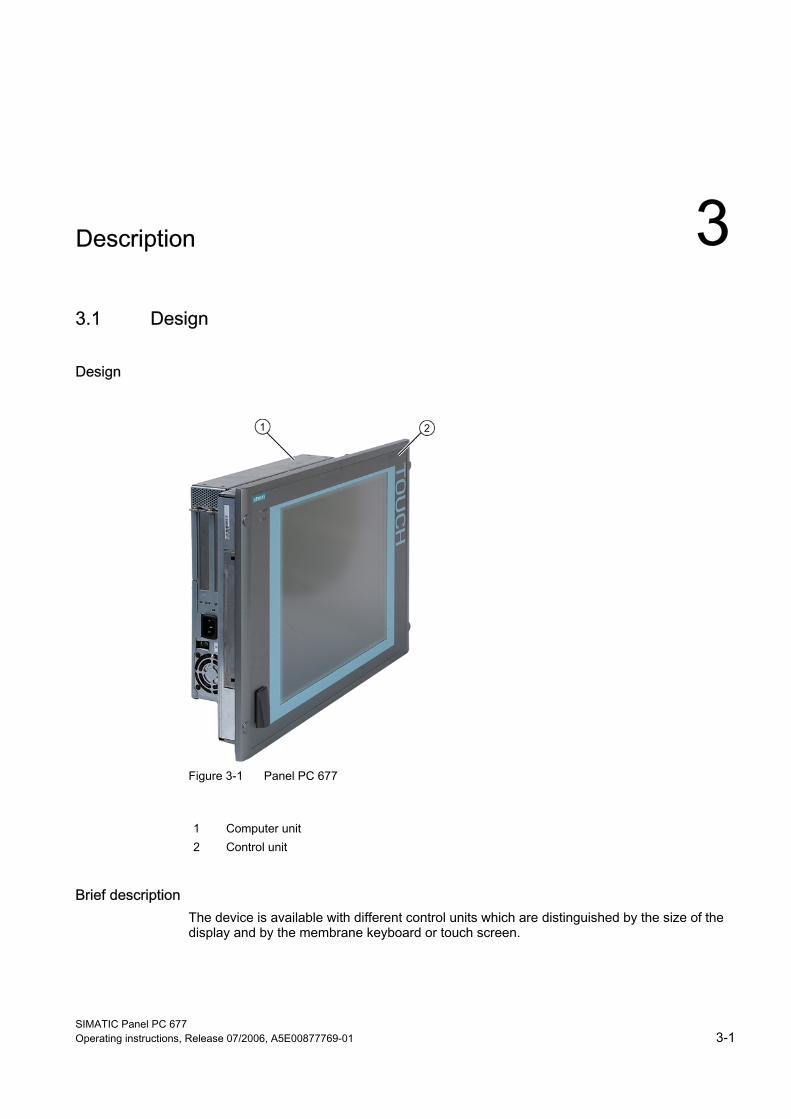
Figure 3-1 Panel PC 677
1 Computer unit 2 Control unit
Brief description The device is available with different control units which are distinguished by the size of the display and by the membrane keyboard or touch screen.
Description 3.1 Design
SIMATIC Panel PC 677 3-2 Operating instructions, Release 07/2006, A5E00877769-01
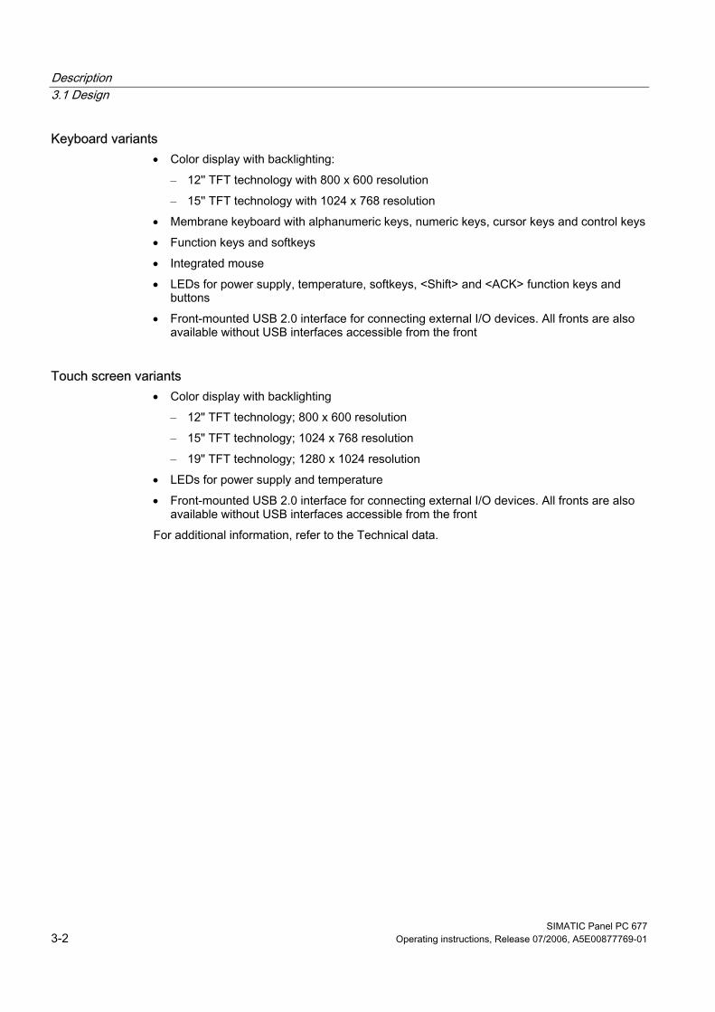
Keyboard variants • Color display with backlighting:
– 12'' TFT technology with 800 x 600 resolution – 15'' TFT technology with 1024 x 768 resolution
• Membrane keyboard with alphanumeric keys, numeric keys, cursor keys and control keys • Function keys and softkeys • Integrated mouse • LEDs for power supply, temperature, softkeys, <Shift> and <ACK> function keys and
buttons • Front-mounted USB 2.0 interface for connecting external I/O devices. All fronts are also
available without USB interfaces accessible from the front
Touch screen variants • Color display with backlighting
– 12" TFT technology; 800 x 600 resolution – 15" TFT technology; 1024 x 768 resolution – 19" TFT technology; 1280 x 1024 resolution
• LEDs for power supply and temperature • Front-mounted USB 2.0 interface for connecting external I/O devices. All fronts are also
available without USB interfaces accessible from the front For additional information, refer to the Technical data.
Description 3.2 Technical features
SIMATIC Panel PC 677 Operating instructions, Release 07/2006, A5E00877769-01 3-3
3.2 3.2 Technical features
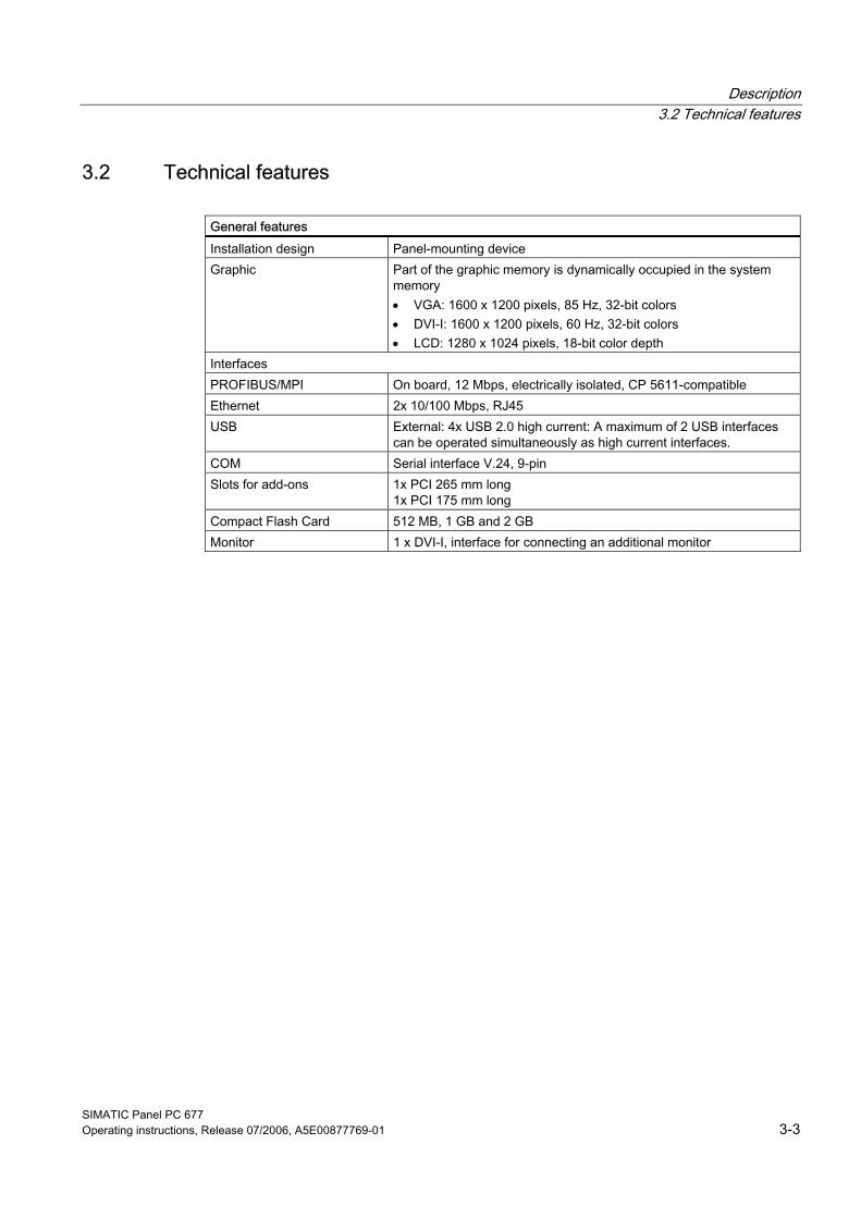
General features Installation design Panel-mounting device Graphic Part of the graphic memory is dynamically occupied in the system
memory • VGA: 1600 x 1200 pixels, 85 Hz, 32-bit colors • DVI-I: 1600 x 1200 pixels, 60 Hz, 32-bit colors • LCD: 1280 x 1024 pixels, 18-bit color depth
Interfaces PROFIBUS/MPI On board, 12 Mbps, electrically isolated, CP 5611-compatible Ethernet 2x 10/100 Mbps, RJ45 USB External: 4x USB 2.0 high current: A maximum of 2 USB interfaces
can be operated simultaneously as high current interfaces. COM Serial interface V.24, 9-pin Slots for add-ons 1x PCI 265 mm long
1x PCI 175 mm long Compact Flash Card 512 MB, 1 GB and 2 GB Monitor 1 x DVI-I, interface for connecting an additional monitor
Description 3.2 Technical features
SIMATIC Panel PC 677 3-4 Operating instructions, Release 07/2006, A5E00877769-01
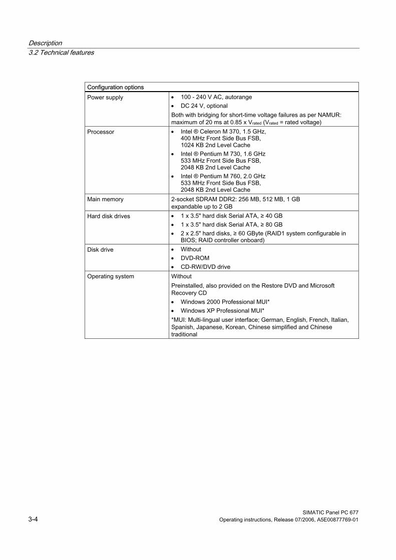
Configuration options Power supply • 100 - 240 V AC, autorange
• DC 24 V, optional Both with bridging for short-time voltage failures as per NAMUR: maximum of 20 ms at 0.85 x Vrated (Vrated = rated voltage)
Processor • Intel ® Celeron M 370, 1.5 GHz, 400 MHz Front Side Bus FSB, 1024 KB 2nd Level Cache
• Intel ® Pentium M 730, 1.6 GHz 533 MHz Front Side Bus FSB, 2048 KB 2nd Level Cache
• Intel ® Pentium M 760, 2.0 GHz 533 MHz Front Side Bus FSB, 2048 KB 2nd Level Cache
Main memory 2-socket SDRAM DDR2: 256 MB, 512 MB, 1 GB expandable up to 2 GB
Hard disk drives • 1 x 3.5" hard disk Serial ATA, ≥ 40 GB • 1 x 3.5" hard disk Serial ATA, ≥ 80 GB • 2 x 2.5" hard disks, ≥ 60 GByte (RAID1 system configurable in
BIOS; RAID controller onboard) Disk drive • Without
• DVD-ROM • CD-RW/DVD drive
Operating system Without Preinstalled, also provided on the Restore DVD and Microsoft Recovery CD • Windows 2000 Professional MUI* • Windows XP Professional MUI* *MUI: Multi-lingual user interface; German, English, French, Italian, Spanish, Japanese, Korean, Chinese simplified and Chinese traditional
Description 3.3 Accessories
SIMATIC Panel PC 677 Operating instructions, Release 07/2006, A5E00877769-01 3-5
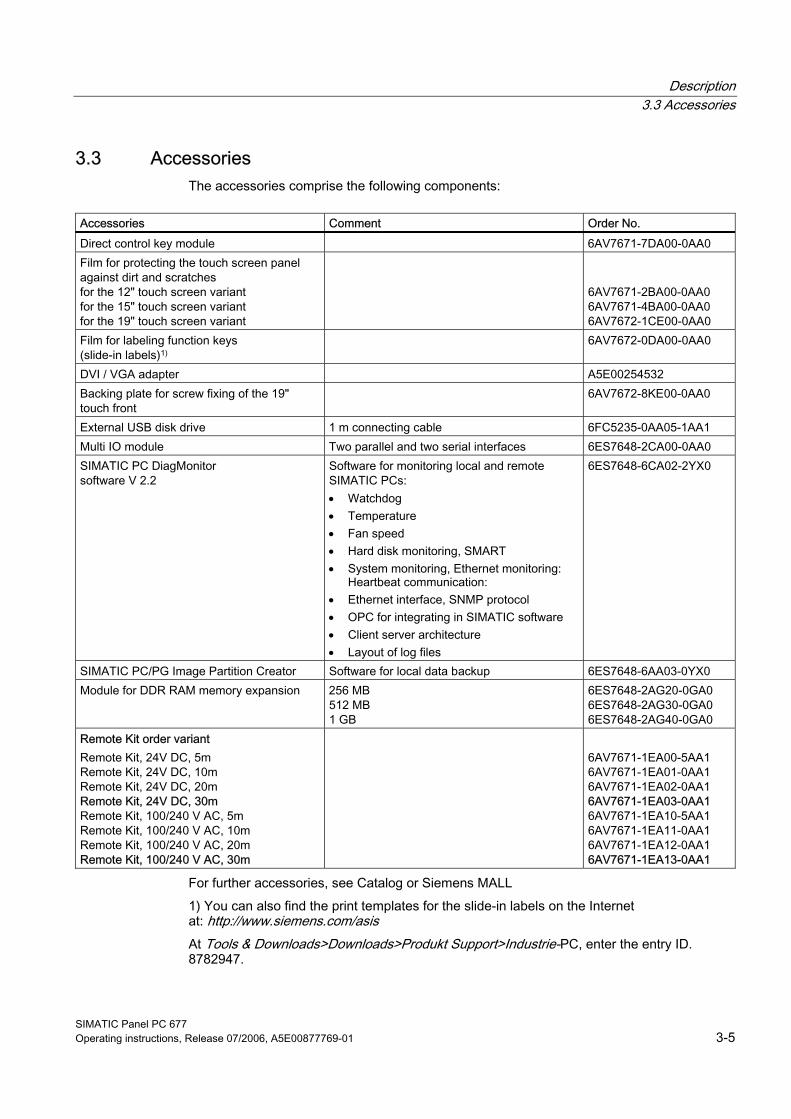
3.3 3.3 Accessories The accessories comprise the following components:
Accessories Comment Order No. Direct control key module 6AV7671-7DA00-0AA0 Film for protecting the touch screen panel against dirt and scratches for the 12" touch screen variant for the 15" touch screen variant for the 19" touch screen variant
6AV7671-2BA00-0AA0 6AV7671-4BA00-0AA0 6AV7672-1CE00-0AA0
Film for labeling function keys (slide-in labels)1)
6AV7672-0DA00-0AA0
DVI / VGA adapter A5E00254532 Backing plate for screw fixing of the 19" touch front
6AV7672-8KE00-0AA0
External USB disk drive 1 m connecting cable 6FC5235-0AA05-1AA1 Multi IO module Two parallel and two serial interfaces 6ES7648-2CA00-0AA0 SIMATIC PC DiagMonitor software V 2.2
Software for monitoring local and remote SIMATIC PCs: • Watchdog • Temperature • Fan speed • Hard disk monitoring, SMART • System monitoring, Ethernet monitoring:
Heartbeat communication: • Ethernet interface, SNMP protocol • OPC for integrating in SIMATIC software • Client server architecture • Layout of log files
6ES7648-6CA02-2YX0
SIMATIC PC/PG Image Partition Creator Software for local data backup 6ES7648-6AA03-0YX0 Module for DDR RAM memory expansion 256 MB
512 MB 1 GB
6ES7648-2AG20-0GA0 6ES7648-2AG30-0GA0 6ES7648-2AG40-0GA0
Remote Kit order variant Remote Kit, 24V DC, 5m Remote Kit, 24V DC, 10m Remote Kit, 24V DC, 20m Remote Kit, 24V DC, 30m Remote Kit, 100/240 V AC, 5m Remote Kit, 100/240 V AC, 10m Remote Kit, 100/240 V AC, 20m Remote Kit, 100/240 V AC, 30m
6AV7671-1EA00-5AA1 6AV7671-1EA01-0AA1 6AV7671-1EA02-0AA1 6AV7671-1EA03-0AA1 6AV7671-1EA10-5AA1 6AV7671-1EA11-0AA1 6AV7671-1EA12-0AA1 6AV7671-1EA13-0AA1
For further accessories, see Catalog or Siemens MALL 1) You can also find the print templates for the slide-in labels on the Internet at: http://www.siemens.com/asis At Tools & Downloads>Downloads>Produkt Support>Industrie-PC, enter the entry ID. 8782947.

SIMATIC Panel PC 677 Operating instructions, Release 07/2006, A5E00877769-01 4-1
Application planning 44.1 4.1 Overview
Introduction This section describes the first steps after unpackaging, the permitted mounting positions and the fixation. This section describes the necessary considerations for EMC.
Field of application The Panel PC is an industry-standard PC platform for demanding tasks in the field of PC-based automation. The Panel PC is designed for on-site use on the machine, installed for example in: • Switchgear cabinet installation • Swivel arm installation • Rack installation
Note In the following, the term "switchgear cabinet" also refers to rack, mounting rack, switchboard, operator panel and console. The term "device" represents the Panel PC and its variants.
Application planning 4.2 Unpacking and checking the delivery
SIMATIC Panel PC 677 4-2 Operating instructions, Release 07/2006, A5E00877769-01
4.2 4.2 Unpacking and checking the delivery
Procedure 1. Please check the packaging material for transport damage upon delivery. 2. If any transport damage is present at the time of delivery, lodge a complaint at the
shipping company in charge. Have the shipper confirm the transport damage immediately.
3. Unpack the device.
Caution Do not lie the device on its back. This will avoid any damage to an optical drive which may be present. Lie the front side on a soft surface to avoid damaging the front panel USB port.
4. Keep the packaging material in case you have to transport the unit again.
Notice The packaging protects the device during transport and storage. Therefore, never dispose of the original packaging material!
5. Please keep the enclosed documentation in a safe place. You will need the documentation when you start up the device for the first time.
6. Check the package contents for completeness and any visible transport damage. Check for completeness using the enclosed scope of delivery list.
7. Should the contents of the package be incomplete or damaged, please inform the responsible supply service immediately and fax us the enclosed form "SIMATIC IPC/PG quality control report".
Warning
Make sure that a damaged device is not installed nor put into operation.
8. Note the identification information as described in the chapter "Identification data of the device".
Application planning 4.3 Device identification data
SIMATIC Panel PC 677 Operating instructions, Release 07/2006, A5E00877769-01 4-3
4.3 4.3 Device identification data
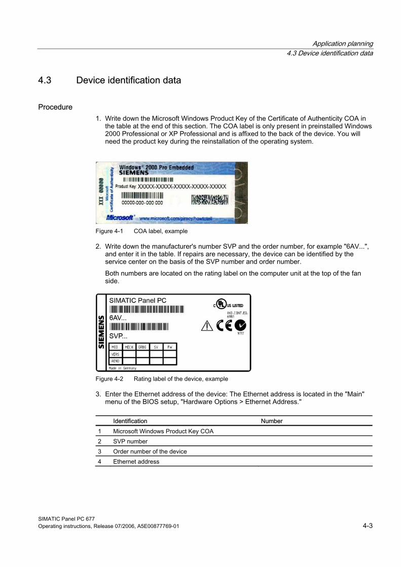
Procedure 1. Write down the Microsoft Windows Product Key of the Certificate of Authenticity COA in
the table at the end of this section. The COA label is only present in preinstalled Windows 2000 Professional or XP Professional and is affixed to the back of the device. You will need the product key during the reinstallation of the operating system.
Figure 4-1 COA label, example
2. Write down the manufacturer's number SVP and the order number, for example "6AV...", and enter it in the table. If repairs are necessary, the device can be identified by the service center on the basis of the SVP number and order number. Both numbers are located on the rating label on the computer unit at the top of the fan side.
Figure 4-2 Rating label of the device, example
3. Enter the Ethernet address of the device: The Ethernet address is located in the "Main" menu of the BIOS setup, "Hardware Options > Ethernet Address."
Identification Number 1 Microsoft Windows Product Key COA 2 SVP number 3 Order number of the device 4 Ethernet address
Application planning 4.4 Mounting Positions and Fastening
SIMATIC Panel PC 677 4-4 Operating instructions, Release 07/2006, A5E00877769-01
4.4 4.4 Mounting Positions and Fastening
4.4.1 Installation guidelines
Before installing the device, read the following general notes relating to installation.
Warning Danger, high voltage Isolate the power supply to the switchgear cabinet before opening it. Ensure that the power to the switchgear cabinet cannot be turned on accidentally.
Caution The device is approved for operation in closed rooms only.
• Ensure that the protective contact socket of the building installation is easily accessible and that there is a mains disconnect switch in switchgear cabinet installations.
• Position the screen in an ergonomic position favorable to the user. Choose a suitable installation height.
• Position the screen so that it is not subject to direct sunlight or other strong sources of light.
• Optical drives are susceptible to shock. Shocks during operation can lead to the loss of data or damage to the drive or data carrier. Optical drives are not only suitable for continuous operation.
• Applies to devices which are installed in swivel arm housings: Avoid rapid or jerky movements of the swivel arm during operation. The ensuing forces could lead to possible irreversible damage of the hard disk. The stops of the swivel arm must be damped in order to avoid any mechanical shock effect to the Panel PC on attachment.
• Applies to devices which are installed in cabinet doors: Prevent the doors being slammed shut. The ensuing forces could lead to possible irreversible damage of the hard disk.
• The device with DC power supply applies in the area of the computer unit and above all the power supply connection in accordance with the UL approval as "open type" or "open equipment". For this reason, the device must be installed in a control cabinet or housing that complies with fire-proofing requirements
Application planning 4.4 Mounting Positions and Fastening
SIMATIC Panel PC 677 Operating instructions, Release 07/2006, A5E00877769-01 4-5
Note The computer unit with AC power supply satisfies fire protection requirements to EN60950-1. It may therefore be installed without additional fire-proofing measures.
• Provide adequate volume in the switchgear cabinet for air circulation and heat transport. Keep at least 10 cm distance between the device and switchgear cabinet.
• Ensure that the maximum air intake temperature, measured 10 cm before the air intake opening on the fan, does not exceed 45°C. The maximum air intake temperature must be accounted for especially when sizing closed switchgear cabinets.
• The minimum distance between the device and the housing is 10 cm on the air output side at the fan.
• Position the device in such a way that the air vents of the housing are not covered up following mounting.
• Ensure there is enough free space in the switchgear cabinet to allow the sheet metal cover to be removed. You will otherwise have to remove the device from the switchgear cabinet or swivel arm when replacing memory or the battery.
• Provide enough free space to add on to the device. • Equip the switchgear cabinet with struts for stabilizing the mounting cut-out. Install struts
where necessary. • Avoid extreme environmental operating conditions. Protect your device against dust,
moisture and heat. • Install the device in such a way (see ChapterTechnical specifications) that it poses no
danger, e.g. by falling over. • During assembly, please comply with the approved installation positions.
Notice If you mount the device in an impermissible installation position or you do not observe the environmental conditions (see ChapterTechnical specifications), you endanger the product safety provided by the UL-approval and compliance with the low-voltage directive (via EN 60950-1). In additional, the functionality of the device is no longer guaranteed.
For additional information, refer to the dimension diagrams in the appendix.
Application planning 4.4 Mounting Positions and Fastening
SIMATIC Panel PC 677 4-6 Operating instructions, Release 07/2006, A5E00877769-01
4.4.2 Installation information stainless steel front Before you install the device, read the additional installation guidelines below: • Make sure that you can access the device from the rear. • The installation cut-out should be deburred. • When operating the device in a switch cabinet, ensure compliance with permitted ambient
conditions and, in particular, that permitted ambient temperatures are not exceeded. Make allowances for the fact that the thermal conductivity of switch cabinets made of stainless steel is not as good as that of an aluminum cabinet.
• Check the flat seal on the device. Always install the device with this flat seal. • Always use the included clamping frame and clamps to mount the device.
Application planning 4.4 Mounting Positions and Fastening
SIMATIC Panel PC 677 Operating instructions, Release 07/2006, A5E00877769-01 4-7
4.4.3 Permitted mounting positions
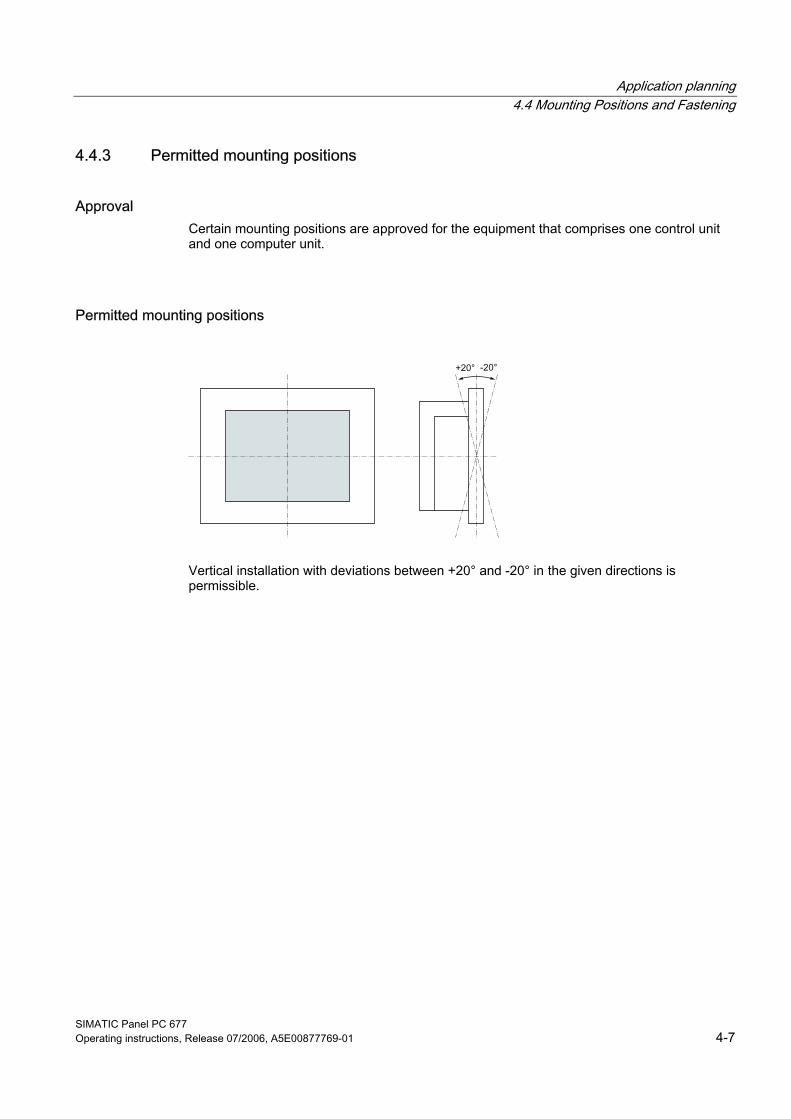
Approval Certain mounting positions are approved for the equipment that comprises one control unit and one computer unit.
Permitted mounting positions
Vertical installation with deviations between +20° and -20° in the given directions is permissible.
Application planning 4.4 Mounting Positions and Fastening
SIMATIC Panel PC 677 4-8 Operating instructions, Release 07/2006, A5E00877769-01
4.4.4 Type of fixation The computer unit is secured in the mounting cut-out either with clamps or screws.
Notice Securing with screws is not possible with the 12" touch screen variant.
Select the type of fixation suitable to your requirements for the degree of protection (see Section Protection against dust and water) .
Application planning 4.4 Mounting Positions and Fastening
SIMATIC Panel PC 677 Operating instructions, Release 07/2006, A5E00877769-01 4-9
4.4.5 Stainless steel front type of fixation
Type of fixation The device is fastened with the included clamps. Additional fastening bore holes or threaded bolts are not required for the control panel.
Type of protection
Caution Degree of protection IP66 is only ensured if the flat gasket of the device is correctly positioned and evenly pressed on the control panel. Refer to the "Installation" section for more information.

Application planning 4.4 Mounting Positions and Fastening
SIMATIC Panel PC 677 4-10 Operating instructions, Release 07/2006, A5E00877769-01
4.4.6 Protection against dust and water
Principle The degree of protection provided at the front is assured when the mounting seal lies completely against the mounting cut-out.
Caution Please ensure that the material strength at the mounting cut-out is a maximum of 6 mm. Please follow the specifications for the dimensions in the "Mounting cut-out" section. The degrees of protection are only guaranteed when the following is observed: • The material strength at the mounting cut-out is at least 2 mm. • The surface plane deviation of the mounting cut-out in relation to the external dimensions
of the control unit amounts to ≤ 0.5 mm when the control unit is mounted.
IP65 degree of protection and NEMA4 IP65 degree of protection and compliance with the NEMA4 regulations are only ensured when clamp mounting together with a ring seal.
IP54 degree of protection This degree of protection is achieved for screw fixing of all operator control units with a key front panel and the 15" and 19" operator control units with a touch front panel. This degree of protection is assured for the 19" operator control unit with a touch front panel when the mounting components for 19" rack accessories are used.
Note For screw fixing of the 19" touch panel front, a backing plate is available as an accessory. For further information, see "http://mall.ad.siemens.com/".
Application planning 4.5 Mounting cut-out
SIMATIC Panel PC 677 Operating instructions, Release 07/2006, A5E00877769-01 4-11
4.5 4.5 Mounting cut-out
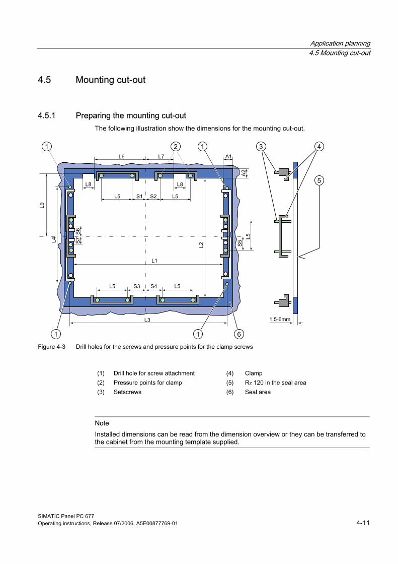
4.5.1 Preparing the mounting cut-out The following illustration show the dimensions for the mounting cut-out.
Figure 4-3 Drill holes for the screws and pressure points for the clamp screws
(1) Drill hole for screw attachment (4) Clamp (2) Pressure points for clamp (5) RZ 120 in the seal area (3) Setscrews (6) Seal area
Note Installed dimensions can be read from the dimension overview or they can be transferred to the cabinet from the mounting template supplied.
Application planning 4.5 Mounting cut-out
SIMATIC Panel PC 677 4-12 Operating instructions, Release 07/2006, A5E00877769-01
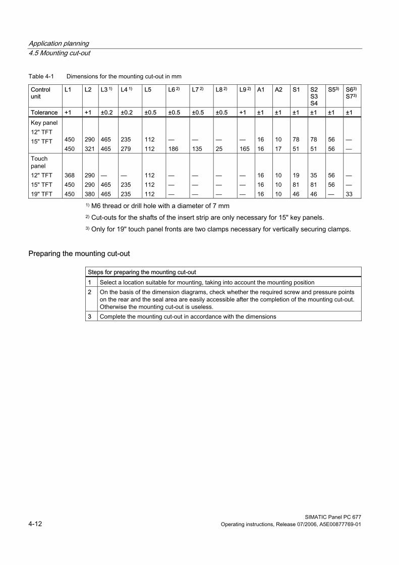
Table 4-1 Dimensions for the mounting cut-out in mm
Control unit
L1 L2 L3 1) L4 1) L5 L6 2) L7 2) L8 2) L9 2) A1 A2 S1 S2 S3 S4
S53) S63)
S73)
Tolerance +1 +1 ±0.2 ±0.2 ±0.5 ±0.5 ±0.5 ±0.5 +1 ±1 ±1 ±1 ±1 ±1 ±1 Key panel 12" TFT 15" TFT
450 450
290 321
465 465
235 279
112 112
— 186
— 135
— 25
— 165
16 16
10 17
78 51
78 51
56 56
— —
Touch panel 12" TFT 15" TFT 19" TFT
368 450 450
290 290 380
— 465 465
— 235 235
112 112 112
— — —
— — —
— — —
— — —
16 16 16
10 10 10
19 81 46
35 81 46
56 56 —
— — 33
1) M6 thread or drill hole with a diameter of 7 mm 2) Cut-outs for the shafts of the insert strip are only necessary for 15" key panels. 3) Only for 19" touch panel fronts are two clamps necessary for vertically securing clamps.
Preparing the mounting cut-out
Steps for preparing the mounting cut-out 1 Select a location suitable for mounting, taking into account the mounting position 2 On the basis of the dimension diagrams, check whether the required screw and pressure points
on the rear and the seal area are easily accessible after the completion of the mounting cut-out. Otherwise the mounting cut-out is useless.
3 Complete the mounting cut-out in accordance with the dimensions
Application planning 4.5 Mounting cut-out
SIMATIC Panel PC 677 Operating instructions, Release 07/2006, A5E00877769-01 4-13
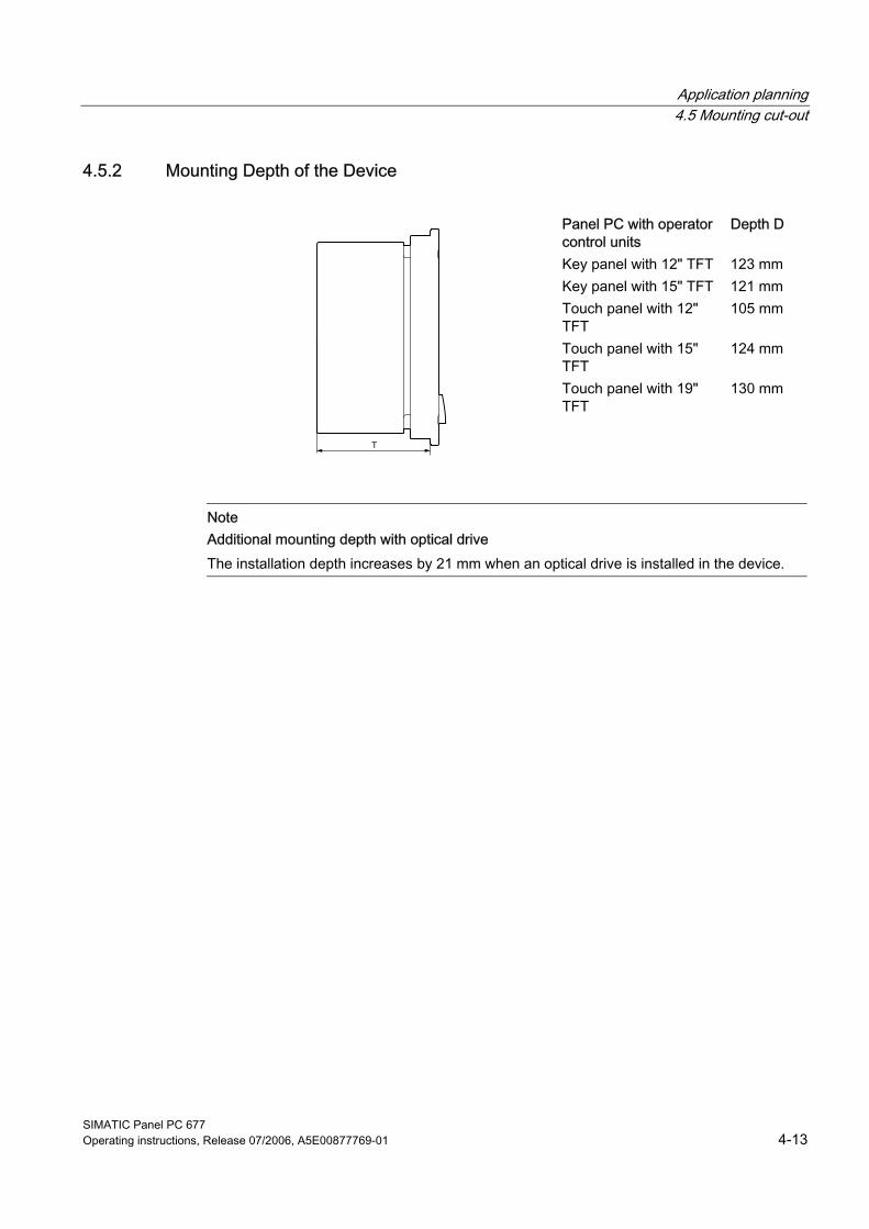
4.5.2 Mounting Depth of the Device
Panel PC with operator control units
Depth D
Key panel with 12" TFT 123 mm Key panel with 15" TFT 121 mm Touch panel with 12" TFT
105 mm
Touch panel with 15" TFT
124 mm
Touch panel with 19" TFT
130 mm
Note Additional mounting depth with optical drive The installation depth increases by 21 mm when an optical drive is installed in the device.
Application planning 4.6 EMC directive
SIMATIC Panel PC 677 4-14 Operating instructions, Release 07/2006, A5E00877769-01
4.6 4.6 EMC directive
Electromagnetic compatibility The device fulfills the requirements of the EMC law of the Federal Republic of Germany as well as the EMC directive of the Single European Market. The device is designed as a built-in device. You ensure compliance with the EN 61000-4-2 (ESD) EMC standard by installing the device in grounded metal cabinets (e.g. 8 MC cabinets, Siemens catalog NV21).
Note For additional information about EMC requirements, refer to the Specifications section.
Installing the device according to EMC directive Basics for interference-free operation: • Install the controller according to EMC directive • Use interference immune cable
Note The instructions "Guidelines for the assembly of interference immune programmable logic controllers" with the article ID 1064706 and the manual "PROFIBUS networks" with the article ID 1971286, which also applies to the installation of the device, is located on the "Documentation and Drivers" CD.

SIMATIC Panel PC 677 Operating instructions, Release 07/2006, A5E00877769-01 5-1
Installation 55.1 5.1 Securing the Device with Clamps
You require 6 clamps in order to mount the device with a 12"/15" display. A device with a 19" display must be mounted with 8 clamps. The required number of clamps is included in your Panel PC delivery package. Required tool for fastening the clamps: 2.5 mm hexagonal spanner
Figure 5-1 Clamp assembly
Rack mounting
Steps for fastening the device with clamps 1 Isolate the device from power supply. 2 Working from the front, insert the device into the 19" rack 3 Fasten the control unit in the rack from the rear using the clamps. Tighten the setscrews to a
torque of 0.4-0.5 Nm
Swivel arm mounting
Steps for fastening the device with clamps 1 Isolate the device from power supply. 2 Working from the front, place the device onto the swivel arm 3 Fasten the control unit on the swivel arm from the rear using the clamps. Tighten the setscrews
to a torque of 0.4-0.5 Nm
Control cabinet installation
Steps for fastening the device with clamps 1 Isolate the device from power supply. 2 Working from the front, insert the device into the mounting cut-out 3 Secure the control unit in the mounting cut-out from behind with the clamps, as shown in the
mounting cut-out in the dimensions. Tighten the setscrews to a torque of 0.4-0.5 Nm
Installation 5.1 Securing the Device with Clamps
SIMATIC Panel PC 677 5-2 Operating instructions, Release 07/2006, A5E00877769-01
IP65 degree of protection The plant builder is responsible for the correct installation of the device. The degree of protection IP65 is only guaranteed for the front of the device if the ring seal is properly applied with the correct size of cutout, the unit has been clamped in place, and the instructions below are observed.
Notice Control cabinet installation: Material strength at the mounting cut-out Please ensure that the material strength at the mounting cut-out is a maximum of 6 mm. Please follow the specifications for the dimensions in the "Preparing the mounting cut-out" section. The degree of protection can only be guaranteed when the following requirements are met: 1. The material strength at the mounting cut-out must be at least 2 mm. 2. The deviation from the plane in relation to the external dimensions for an installed HMI device is ≤ 0.5 mm
Installation 5.2 Securing the Device with Screws
SIMATIC Panel PC 677 Operating instructions, Release 07/2006, A5E00877769-01 5-3
5.2 5.2 Securing the Device with Screws
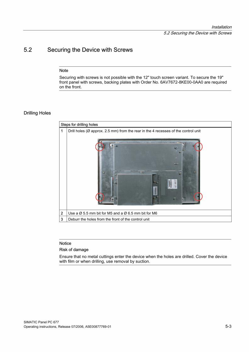
Note Securing with screws is not possible with the 12" touch screen variant. To secure the 19" front panel with screws, backing plates with Order No. 6AV7672-8KE00-0AA0 are required on the front.
Drilling Holes
Steps for drilling holes 1 Drill holes (Ø approx. 2.5 mm) from the rear in the 4 recesses of the control unit
2 Use a Ø 5.5 mm bit for M5 and a Ø 6.5 mm bit for M6 3 Deburr the holes from the front of the control unit
Notice Risk of damage Ensure that no metal cuttings enter the device when the holes are drilled. Cover the device with film or when drilling, use removal by suction.
Installation 5.2 Securing the Device with Screws
SIMATIC Panel PC 677 5-4 Operating instructions, Release 07/2006, A5E00877769-01
Rack mounting
Steps for fastening the device with screws 1 Make drill holes at the prepared mounting cut-out in accordance with the specifications for L4
and L5, as shown at the dimensions in the mounting cut-out 2 Working from the front, insert the device into the 19" rack 3 Secure the control unit by inserting suitable screws through the holes and attaching nuts
Swivel arm mounting
Steps for fastening the device with screws 1 Make drill holes at the prepared mounting cut-out in accordance with the specifications for L4
and L5, as shown at the dimensions in the mounting cut-out 2 Working from the front, place the device onto the swivel arm 3 Secure the control unit by inserting suitable screws through the holes and attaching nuts
Control cabinet installation
Steps for fastening the device with screws 1 Make drill holes at the prepared mounting cut-out in accordance with the specifications for L4
and L5, as shown at the dimensions in the mounting cut-out 2 Carefully drill the respective holes in the control unit at the designated location from the rear 3 Working from the front, insert the device into the mounting cut-out 4 Secure the control unit by inserting suitable screws through the holes and attaching nuts
Installation 5.2 Securing the Device with Screws
SIMATIC Panel PC 677 Operating instructions, Release 07/2006, A5E00877769-01 5-5
IP54 degree of protection The IP54 degree of protection is guaranteed for mounting together with the ring seal.
Caution Observe the panel seal when mounting Ensure you do not damage the panel seal when mounting the device.
Notice Control cabinet installation: Material strength at the mounting cut-out Please ensure that the material strength at the mounting cut-out is a maximum of 6 mm. Please follow the specifications for the dimensions in the "Preparing the mounting cut-out" section. The degree of protection can only be guaranteed when the following requirements are met: 1. The material strength at the mounting cut-out must be at least 2 mm. 2. The deviation from the plane in relation to the external dimensions for an installed HMI device is ≤ 0.5 mm

Installation 5.3 Fix the device with stainless steel front using clamps
SIMATIC Panel PC 677 5-6 Operating instructions, Release 07/2006, A5E00877769-01
5.3 5.3 Fix the device with stainless steel front using clamps
Introduction This section describes how to mount the device in a control panel.
Caution Mount the device as intended. This will avoid damage to the device and loss of warranty. Follow the installation instructions.
Procedure 1. Ensure that the flat gasket does not become twisted during mounting, otherwise the
mounting cut-out may not be correctly sealed. 2. Working from the front, insert the device into the prepared and deburred mounting cut-
out. Take the necessary precautions to ensure the device cannot drop out of the control panel before it has been secured in place.
3. Place the clamping frame with the centering bore holes onto the device. Make sure that the flat side of the frame makes contact with the back of the control panel.
Figure 5-2 Clamping frame with flat seal
Installation 5.3 Fix the device with stainless steel front using clamps
SIMATIC Panel PC 677 Operating instructions, Release 07/2006, A5E00877769-01 5-7
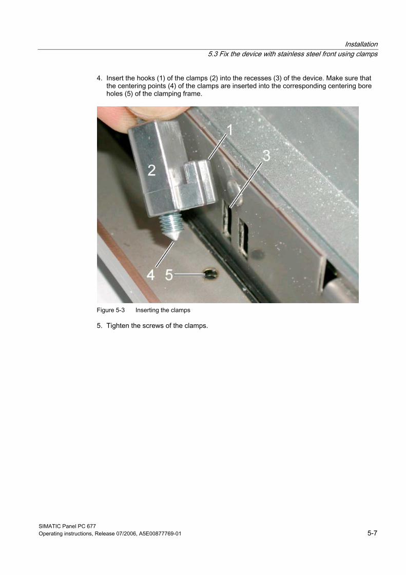
4. Insert the hooks (1) of the clamps (2) into the recesses (3) of the device. Make sure that the centering points (4) of the clamps are inserted into the corresponding centering bore holes (5) of the clamping frame.
Figure 5-3 Inserting the clamps
5. Tighten the screws of the clamps.
Installation 5.3 Fix the device with stainless steel front using clamps
SIMATIC Panel PC 677 5-8 Operating instructions, Release 07/2006, A5E00877769-01
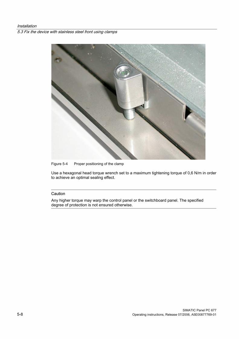
Figure 5-4 Proper positioning of the clamp
Use a hexagonal head torque wrench set to a maximum tightening torque of 0,6 N/m in order to achieve an optimal sealing effect.
Caution Any higher torque may warp the control panel or the switchboard panel. The specified degree of protection is not ensured otherwise.
Installation 5.3 Fix the device with stainless steel front using clamps
SIMATIC Panel PC 677 Operating instructions, Release 07/2006, A5E00877769-01 5-9
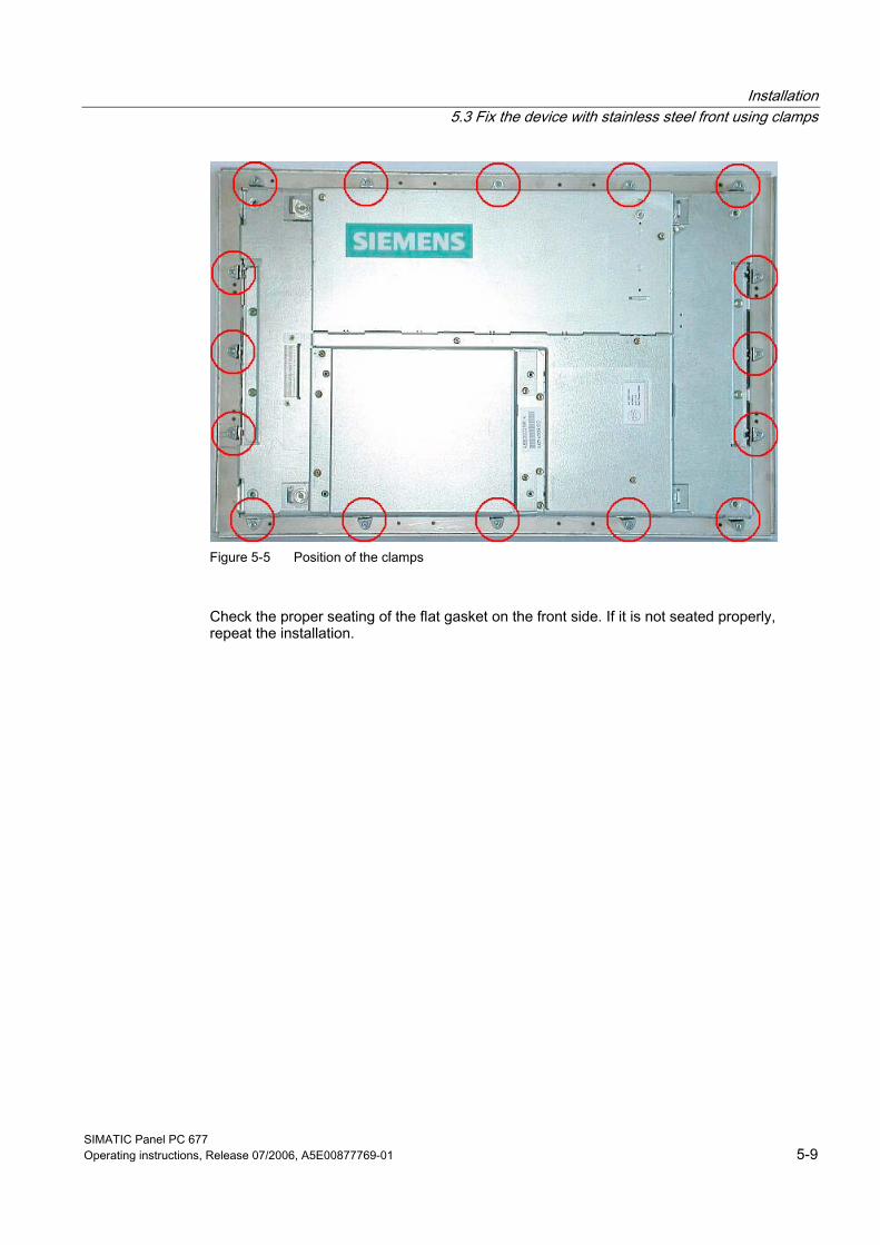
Figure 5-5 Position of the clamps
Check the proper seating of the flat gasket on the front side. If it is not seated properly, repeat the installation.
Installation 5.3 Fix the device with stainless steel front using clamps
SIMATIC Panel PC 677 5-10 Operating instructions, Release 07/2006, A5E00877769-01
SIMATIC Panel PC 677 Operating instructions, Release 07/2006, A5E00877769-01 6-1
Connecting 66.1 6.1 Connection and Operator Control Components
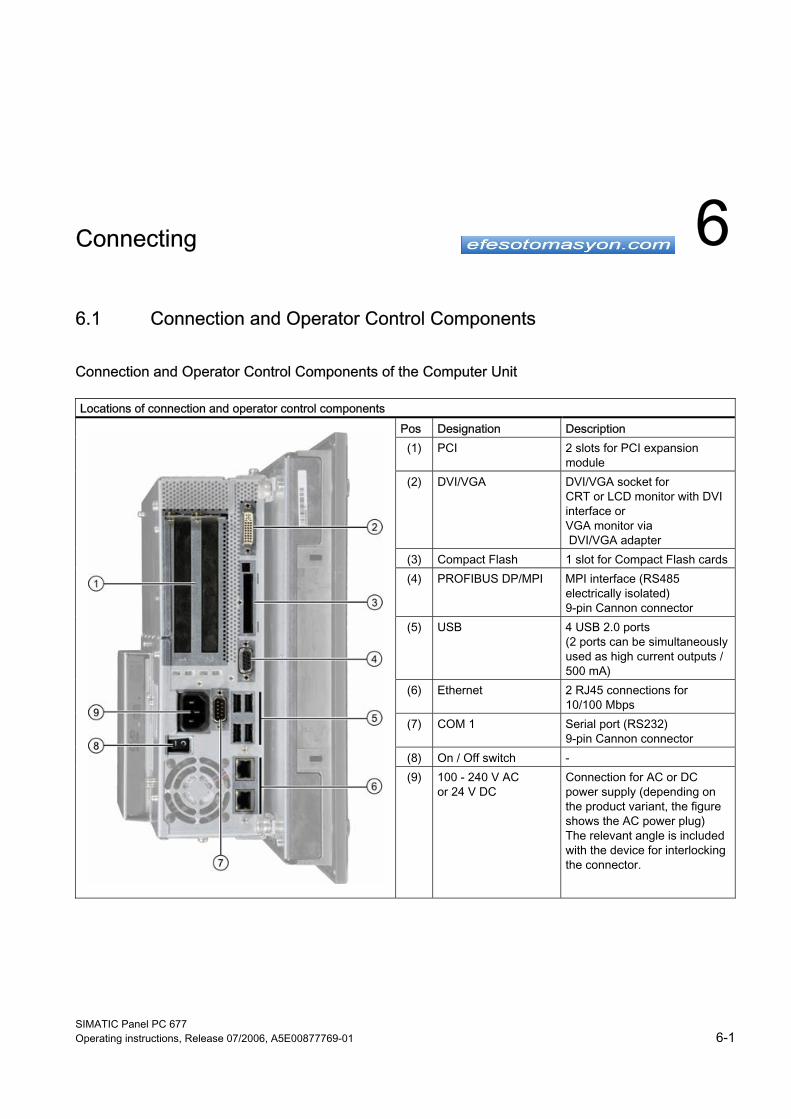
Connection and Operator Control Components of the Computer Unit Locations of connection and operator control components
Pos Designation Description (1) PCI 2 slots for PCI expansion
module (2) DVI/VGA DVI/VGA socket for
CRT or LCD monitor with DVI interface or VGA monitor via DVI/VGA adapter
(3) Compact Flash 1 slot for Compact Flash cards (4) PROFIBUS DP/MPI MPI interface (RS485
electrically isolated) 9-pin Cannon connector
(5) USB 4 USB 2.0 ports (2 ports can be simultaneously used as high current outputs / 500 mA)
(6) Ethernet 2 RJ45 connections for 10/100 Mbps
(7) COM 1 Serial port (RS232) 9-pin Cannon connector
(8) On / Off switch -
(9) 100 - 240 V AC or 24 V DC
Connection for AC or DC power supply (depending on the product variant, the figure shows the AC power plug) The relevant angle is included with the device for interlocking the connector.
Connecting 6.1 Connection and Operator Control Components
SIMATIC Panel PC 677 6-2 Operating instructions, Release 07/2006, A5E00877769-01
Notice On / Off switch The On / Off switch does not disconnect the device from mains. When the switch is in the 0 position, the device is still connected to the auxiliary voltage.
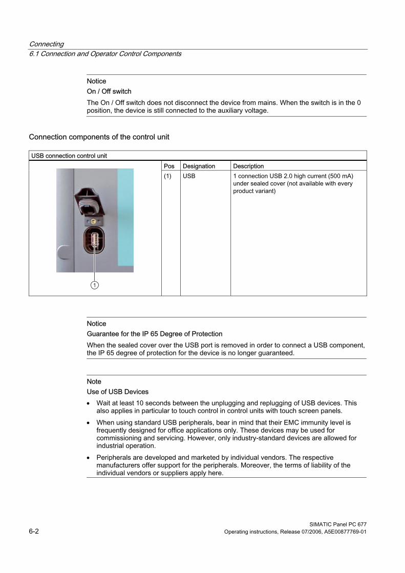
Connection components of the control unit USB connection control unit
Pos Designation Description
(1) USB 1 connection USB 2.0 high current (500 mA) under sealed cover (not available with every product variant)
Notice Guarantee for the IP 65 Degree of Protection When the sealed cover over the USB port is removed in order to connect a USB component, the IP 65 degree of protection for the device is no longer guaranteed.
Note Use of USB Devices • Wait at least 10 seconds between the unplugging and replugging of USB devices. This
also applies in particular to touch control in control units with touch screen panels. • When using standard USB peripherals, bear in mind that their EMC immunity level is
frequently designed for office applications only. These devices may be used for commissioning and servicing. However, only industry-standard devices are allowed for industrial operation.
• Peripherals are developed and marketed by individual vendors. The respective manufacturers offer support for the peripherals. Moreover, the terms of liability of the individual vendors or suppliers apply here.
Connecting 6.2 Connecting the 100 V to 240 V AC power supply
SIMATIC Panel PC 677 Operating instructions, Release 07/2006, A5E00877769-01 6-3
6.2 6.2 Connecting the 100 V to 240 V AC power supply
General connection information Note the following in order to operate the device safely and according to regulation:
Note Voltage Range The power supply is designed for 100 - 240 V AC networks. The device adjusts automatically to the voltage.
Notice Risk of damage Do not connect or disconnect power and data cables during a thunderstorm.
Notice Power Supply Network The device is designed for operation on grounded power supply networks (TN systems to VDE 0100, Part 300, or IEC 60364-3). It is not permissible for operation on ungrounded or impedance-grounded power networks (IT networks).
Notice Permitted Mains Voltage The local rated voltage must be within the voltage range of the device.
Notice Power Disconnection The built-in switch does not disconnect the device from mains. The mains connector on the device must be disconnected to fully isolate the device from mains. The mains connector must be easily accessible. If this cannot be guaranteed, in cabinet installation, for example, or the mains connector clamp is used, an easily accessible power switch must be built into the device.

Connecting 6.2 Connecting the 100 V to 240 V AC power supply
SIMATIC Panel PC 677 6-4 Operating instructions, Release 07/2006, A5E00877769-01
Power Factor Correction The power supply contains an active PFC (Power Factor Correction) circuit to conform to the EMC guidelines. Uninterruptible AC power systems (UPS) must supply a sinusoidal output voltage in the normal and buffered mode when used with SIMATIC PCs with an active PFC. UPS characteristics are described and classified in the standards EN 50091-3 and IEC 62040-3. Devices with sinusoidal output voltage in the normal and buffered mode are identified with the classification “VFI-SS-....” or “VI-SS-....”.
Notice Risk of damage Operation of the device on a non-sinusoidal mains voltage can cause damage to the power supply unit.
Country-specific Connection Information For the USA and Canada For the United States and Canada, a CSA or UL-listed power cord must be used. The connector must be compliant with NEMA 5-15. Country-specific power cables are available as accessories. • 120 V supply voltage
Use a flexible power cord with UL approval and with CSA label, and with the following features: Type SJT with three leads, min. 18 AWG conductor cross-section, max. 4.5 m in length and parallel ground contact connector 15 A, min. 125 V
• 230 V AC power supply To be used is a flexible power cord approved to UL and with CSA label, and which has the following features: Type SJT with three leads, min. 18 AWG conductor cross-section, max. 4.5 m long and tandem ground contact connector 15 A, min. 250 V
For countries other than the USA and Canada • Please observe the country-specific supply voltage
This device is equipped with a safety-tested power cord which may only be connected to ground contact power outlet. If you choose not to use this cable, you must use a flexible cable of the following type: Min 18 AWG conductor cross-section and 15-A / 250-V shockproof connector. The cable set must be compliant with the safety regulations and stipulated IDs of the country where the system is to be installed.
Connecting the power supply
Steps for connecting the device to the 100 - 240 V AC power supply 1 Switch off the AC power source 2 Connect the power supply using the connector
Power consumption Depending on the size of the display and taking into account 15 W per PCI slot, the power consumption for devices with 12" and 15" operator control units is max. 140 W, and with 19" operator control units it is max. 163 W.
Connecting 6.3 Connecting the 24 V DC power supply
SIMATIC Panel PC 677 Operating instructions, Release 07/2006, A5E00877769-01 6-5
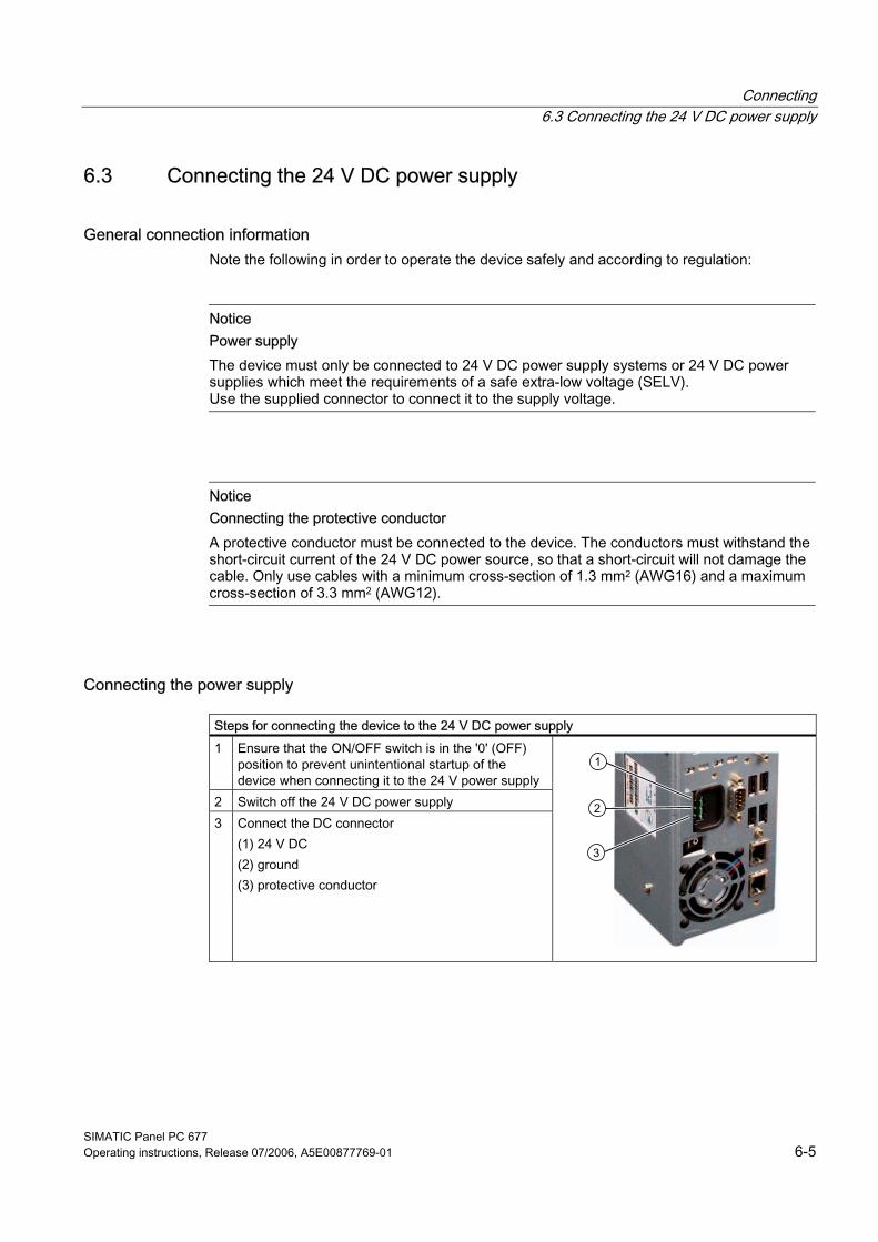
6.3 6.3 Connecting the 24 V DC power supply
General connection information Note the following in order to operate the device safely and according to regulation:
Notice Power supply The device must only be connected to 24 V DC power supply systems or 24 V DC power supplies which meet the requirements of a safe extra-low voltage (SELV). Use the supplied connector to connect it to the supply voltage.
Notice Connecting the protective conductor A protective conductor must be connected to the device. The conductors must withstand the short-circuit current of the 24 V DC power source, so that a short-circuit will not damage the cable. Only use cables with a minimum cross-section of 1.3 mm2 (AWG16) and a maximum cross-section of 3.3 mm2 (AWG12).
Connecting the power supply
Steps for connecting the device to the 24 V DC power supply 1 Ensure that the ON/OFF switch is in the '0' (OFF)
position to prevent unintentional startup of the device when connecting it to the 24 V power supply
2 Switch off the 24 V DC power supply 3 Connect the DC connector
(1) 24 V DC (2) ground (3) protective conductor
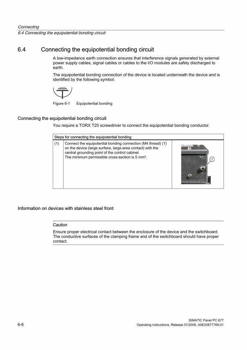
Connecting 6.4 Connecting the equipotential bonding circuit
SIMATIC Panel PC 677 6-6 Operating instructions, Release 07/2006, A5E00877769-01
6.4 6.4 Connecting the equipotential bonding circuit A low-impedance earth connection ensures that interference signals generated by external power supply cables, signal cables or cables to the I/O modules are safely discharged to earth. The equipotential bonding connection of the device is located underneath the device and is identified by the following symbol:
Figure 6-1 Equipotential bonding
Connecting the equipotential bonding circuit You require a TORX T20 screwdriver to connect the equipotential bonding conductor.
Steps for connecting the equipotential bonding (1) Connect the equipotential bonding connection (M4 thread) (1)
on the device (large surface, large-area contact) with the central grounding point of the control cabinet. The minimum permissible cross-section is 5 mm2.
Information on devices with stainless steel front
Caution Ensure proper electrical contact between the enclosure of the device and the switchboard. The conductive surfaces of the clamping frame and of the switchboard should have proper contact.
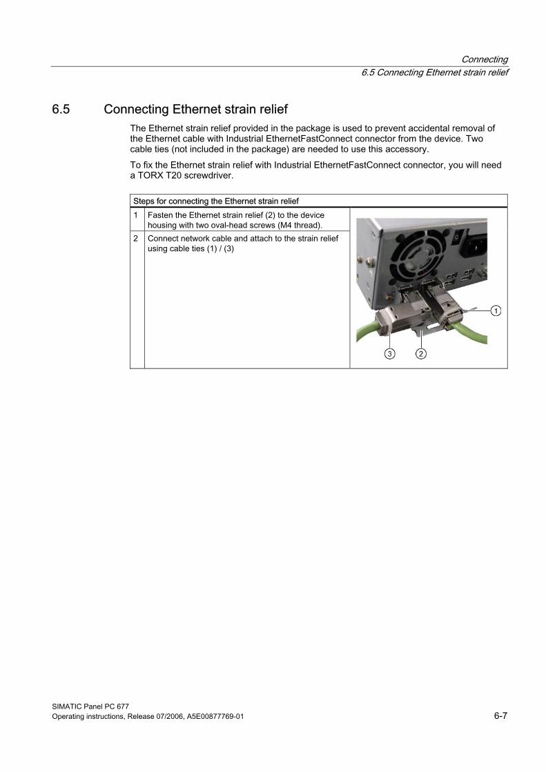
Connecting 6.5 Connecting Ethernet strain relief
SIMATIC Panel PC 677 Operating instructions, Release 07/2006, A5E00877769-01 6-7
6.5 6.5 Connecting Ethernet strain relief The Ethernet strain relief provided in the package is used to prevent accidental removal of the Ethernet cable with Industrial EthernetFastConnect connector from the device. Two cable ties (not included in the package) are needed to use this accessory. To fix the Ethernet strain relief with Industrial EthernetFastConnect connector, you will need a TORX T20 screwdriver.
Steps for connecting the Ethernet strain relief 1 Fasten the Ethernet strain relief (2) to the device
housing with two oval-head screws (M4 thread). 2 Connect network cable and attach to the strain relief
using cable ties (1) / (3)
Connecting 6.6 Connecting the power plug locking mechanism
SIMATIC Panel PC 677 6-8 Operating instructions, Release 07/2006, A5E00877769-01
6.6 6.6 Connecting the power plug locking mechanism
The power plug locking mechanism is part of the scope of supply and prevents the power plug from being pulled out accidentally. The power plug locking mechanism is a metal bracket that is screwed onto the computer housing. You require a TORX T20 screwdriver for attaching it to the housing. The power plug locking mechanism is a safety-relevant part. To completely disconnect the device from mains see Chapter AC power supply (AC 100 / 240 V), section Power disconnection.
SIMATIC Panel PC 677 Operating instructions, Release 07/2006, A5E00877769-01 7-1
Integration into an automation system 77.1 7.1 Overview
Introduction The following options are available for integrating the device in existing or planned system environments and networks.
Ethernet The integrated Ethernet interface can be used for communication and for data exchange with automation devices such as SIMATIC S7. You require suitable software for this: STEP7, WinCC, WinCC flexible, WinAC, SIMATIC NET.
PROFIBUS / MPI The potentially isolated Profibus interface can be used to connect distributed field devices or to couple with SIMATIC S7. You require suitable software for this: STEP7, WinCC, WinCC flexible, WinAC, SIMATIC NET.
Additional information For further information, refer to the catalog and to the online ordering system of Siemens A&D. Internet address: https://mall.ad.siemens.com
Integration into an automation system 7.2 Device in a SIMATIC S7 configuration
SIMATIC Panel PC 677 7-2 Operating instructions, Release 07/2006, A5E00877769-01
7.2 7.2 Device in a SIMATIC S7 configuration
7.2.1 MPI/PROFIBUS-DP network You can connect the device to a SIMATIC S7 automation system or a PROFIBUS DP network via the MPI/DP interface. You can connect up to 32 PC, PG, or AS devices to one network segment. The use of repeaters allows you to interconnect several MPI/PROFIBUS DP network segments. The complete MPI/PROFIBUS DP network consists of a maximum of 127 stations. The device is physically connected to the MPI/PROFIBUS DP network via an electrically isolated RS485 interface on the PC motherboard. The potential is isolated within the safety low voltage circuit (SELV). The transmission rate is limited to 187.5 Kbps with the 5-meter MPI cable for connecting to the SIMATIC S7-CPU. To achieve baud rates over 1.5 Mbps, you require a 12 Mbps PROFIBUS cable with the order number 6ES7901-4BD00-0XA0. In the PROFIBUS DP MPI network, you can achieve data transmission rates of 9.6 Kbps to 12 Mbps.
Integration into an automation system 7.2 Device in a SIMATIC S7 configuration
SIMATIC Panel PC 677 Operating instructions, Release 07/2006, A5E00877769-01 7-3
7.2.2 Connecting an S7 automation system
Coupling The device is coupled via the MPI/DP interface as follows: • With MPI networks S7-200, S7-300, and S7-400 • PROFIBUS DP networks with DP components
Hardware requirements You can use the following components for coupling or networking with PROFIBUS: • RS 485 interface, MPI/DP interface, onboard • PROFIBUS cable
Note Refer to the SIMATIC Net catalog IK PI for more information about SIMATIC Net PC cards.
Procedure 1. Disconnect the device from mains.
Caution Risk of damage to the device! Neutralize the static charge of your body, the device, and the connecting cables. You can do this by briefly touching the metal housing with the cable in your hand.
2. Insert the PROFIBUS cable in the MPI/DP socket. 3. Reconnect the device to the electrical power system.
Integration into an automation system 7.3 Networking via Industrial Ethernet
SIMATIC Panel PC 677 7-4 Operating instructions, Release 07/2006, A5E00877769-01
7.3 7.3 Networking via Industrial Ethernet You can establish a network between the device and other computers via Industrial Ethernet. The on-board LAN is a Twisted-Pair (TP) interface for data transfer rates of 10/100 Mbit/s. The interface is Plug and Play-ready and is automatically detected in Windows. Protocol settings are made in the Windows control panel.
Notice A Class 5, CAT 5 Ethernet cable is required for 100 Mbit/s operation.
SIMATIC Panel PC 677 Operating instructions, Release 07/2006, A5E00877769-01 8-1
Commissioning 88.1 8.1 Overview
Check list Before starting up the device for the first time, go through the following checklist: • Have you taken into account the proper ambient and environmental conditions for the
device, as described in the Technical data? • Have you connected the equipotential bonding if required? • Have you checked that the power supply is connected correctly and that the values are
appropriate? • Read over this information in the respective "Connecting" chapter of the operating
instructions. Please follow all guidelines
Caution Condensation When transporting the device at low temperatures, ensure that no moisture gets on or into the device. This also applies if the device is subjected to extreme changes in temperature. Wait 12 hours before switching the device on. Allow the device to slowly adjust to room temperature before commissioning the device. Do not subject the device to direct heat radiation from devices such as heaters.
Requirement • The equipotential bonding is connected. • The cables are correctly plugged in • A USB keyboard and a USB mouse are connected
Commissioning 8.2 Switch on the device
SIMATIC Panel PC 677 8-2 Operating instructions, Release 07/2006, A5E00877769-01
8.2 8.2 Switch on the device
Procedure 1. Switch on the external AC or DC supply. 2. Connect the external keyboard and mouse. 3. Switch on the equipment using the switch next to the supply connector. 4. The "POWER" LED will light up: The device starts up and boots.
Self-test After switching on, the device performs a self test. During the self test, the message "Press <F2> to enter SETUP" appears briefly. Do not press this key during this first start up. When the self-test is finished, the operating system will be loaded. You will see this from the screen display.
5. Before you install additional hardware in the SIMATIC Panel PC, such as a PCI card, please start up the equipment once without it.
Commissioning 8.3 Setting up the Microsoft Windows operating system
SIMATIC Panel PC 677 Operating instructions, Release 07/2006, A5E00877769-01 8-3
8.3 8.3 Setting up the Microsoft Windows operating system
Introduction The setup wizard appears immediately following the startup of the device. The wizard is used to set the parameters of the operating system.
Note The dialogs of the setup wizards differ slightly in some places for the Windows 2000 Professional and Windows XP Professional operating systems. In order to change to the next dialog, click on the ">>" button. In order to change the entry in the previous dialog, click on the "<<" button.
Procedure 1. Accept the Microsoft licensing agreement. 2. Leave the regional settings of the operating system unchanged. If required, adjust the
regional settings of the operating system only after commissioning. 3. Enter the company names and user names. 4. If this PC name is already in use as you attempt to connect the device to a network: Enter
a new PC name for identification. The operating system will restart automatically.
The system settings are updated. The desktop is set up. The setup of the operating system is complete.
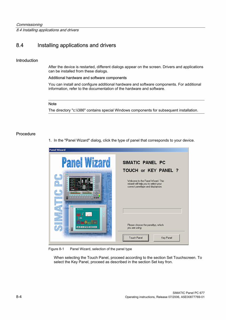
Commissioning 8.4 Installing applications and drivers
SIMATIC Panel PC 677 8-4 Operating instructions, Release 07/2006, A5E00877769-01
8.4 8.4 Installing applications and drivers
Introduction After the device is restarted, different dialogs appear on the screen. Drivers and applications can be installed from these dialogs. Additional hardware and software components You can install and configure additional hardware and software components. For additional information, refer to the documentation of the hardware and software.
Note The directory "c:\i386" contains special Windows components for subsequent installation.
Procedure 1. In the "Panel Wizard" dialog, click the type of panel that corresponds to your device.
Figure 8-1 Panel Wizard, selection of the panel type
When selecting the Touch Panel, proceed according to the section Set Touchscreen. To select the Key Panel, proceed as described in the section Set key fron.
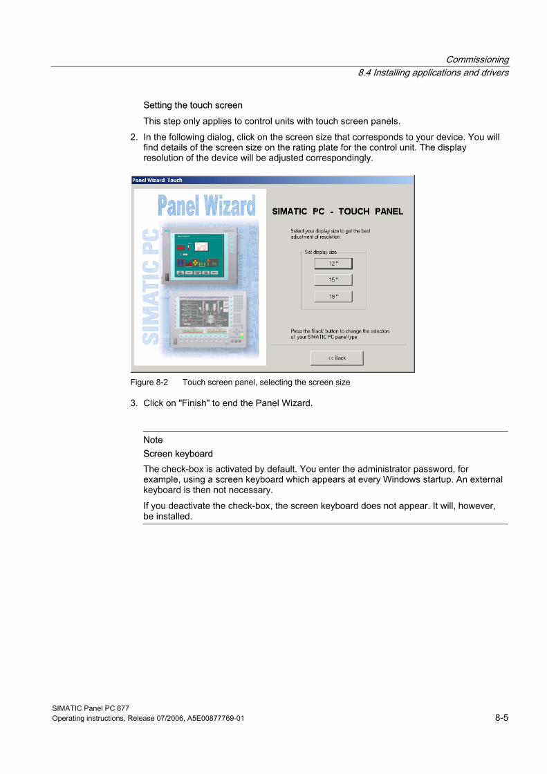
Commissioning 8.4 Installing applications and drivers
SIMATIC Panel PC 677 Operating instructions, Release 07/2006, A5E00877769-01 8-5
Setting the touch screen This step only applies to control units with touch screen panels.
2. In the following dialog, click on the screen size that corresponds to your device. You will find details of the screen size on the rating plate for the control unit. The display resolution of the device will be adjusted correspondingly.
Figure 8-2 Touch screen panel, selecting the screen size
3. Click on "Finish" to end the Panel Wizard.
Note Screen keyboard The check-box is activated by default. You enter the administrator password, for example, using a screen keyboard which appears at every Windows startup. An external keyboard is then not necessary. If you deactivate the check-box, the screen keyboard does not appear. It will, however, be installed.
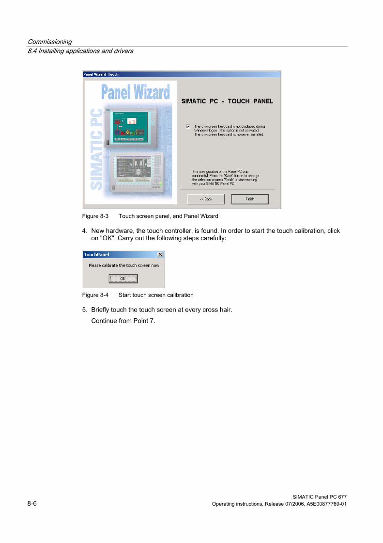
Commissioning 8.4 Installing applications and drivers
SIMATIC Panel PC 677 8-6 Operating instructions, Release 07/2006, A5E00877769-01
Figure 8-3 Touch screen panel, end Panel Wizard
4. New hardware, the touch controller, is found. In order to start the touch calibration, click on "OK". Carry out the following steps carefully:
Figure 8-4 Start touch screen calibration
5. Briefly touch the touch screen at every cross hair. Continue from Point 7.
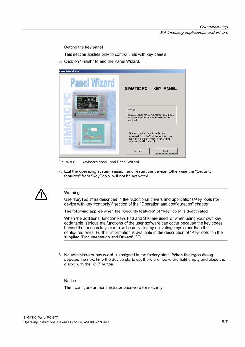
Commissioning 8.4 Installing applications and drivers
SIMATIC Panel PC 677 Operating instructions, Release 07/2006, A5E00877769-01 8-7
Setting the key panel This section applies only to control units with key panels.
6. Click on "Finish" to end the Panel Wizard.
Figure 8-5 Keyboard panel, end Panel Wizard
7. Exit the operating system session and restart the device. Otherwise the "Security features" from "KeyTools" will not be activated.
Warning
Use "KeyTools" as described in the "Additional drivers and applications/KeyTools (for device with key front only)" section of the "Operation and configuration" chapter. The following applies when the "Security features" of "KeyTools" is deactivated: When the additional function keys F13 and S16 are used, or when using your own key code table, serious malfunctions of the user software can occur because the key codes behind the function keys can also be activated by activating keys other than the configured ones. Further information is available in the description of "KeyTools" on the supplied "Documentation and Drivers" CD.
8. No administrator password is assigned in the factory state. When the logon dialog appears the next time the device starts up, therefore, leave the field empty and close the dialog with the "OK" button.
Notice Then configure an administrator password for security.
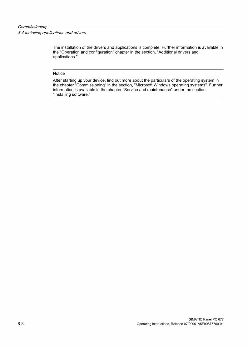
Commissioning 8.4 Installing applications and drivers
SIMATIC Panel PC 677 8-8 Operating instructions, Release 07/2006, A5E00877769-01
The installation of the drivers and applications is complete. Further information is available in the "Operation and configuration" chapter in the section, "Additional drivers and applications."
Notice After starting up your device, find out more about the particulars of the operating system in the chapter "Commissioning" in the section, "Microsoft Windows operating systems". Further information is available in the chapter "Service and maintenance" under the section, "Installing software."
Commissioning 8.5 BIOS settings
SIMATIC Panel PC 677 Operating instructions, Release 07/2006, A5E00877769-01 8-9
8.5 8.5 BIOS settings The BIOS setting "USB legacy Support" is enabled by default. Thus, the complete functionality of a USB keyboard is available prior to starting up Windows. You can also adjust the BIOS settings with the USB keyboard.
Note To edit the BIOS on an operator device equipped with a touch screen, connect a USB keyboard.

Commissioning 8.6 Microsoft Windows operating systems
SIMATIC Panel PC 677 8-10 Operating instructions, Release 07/2006, A5E00877769-01
8.6 8.6 Microsoft Windows operating systems
8.6.1 Approvals The device is approved for use with the following operating systems:
Approvals • Windows 2000 Professional Multi-Language SP4 and higher, German, English, French,
Italian, Spanish, Japanese, Korean, Chinese Simplified and Chinese Traditional • Windows XP Professional Multi-Language, German, English, French, Italian, Spanish,
Japanese, Korean, Chinese Simplified and Chinese Traditional Windows XP Professional is only approved as of Service Pack 2. The operating system is provided with the Windows function modes "Hibernate" and "Standby" deactivated when shutting down the operating system and with "Fast User Switch" (Windows XP Professional) deactivated.

Commissioning 8.6 Microsoft Windows operating systems
SIMATIC Panel PC 677 Operating instructions, Release 07/2006, A5E00877769-01 8-11
8.6.2 Windows 2000 Professional
Service pack After a new installation of Windows 2000 Professional, install at least Service Pack 4. Service Pack 4 is supplied in the product package.
Note If you are using SIMATIC WinCC or SIMATIC WinCC flexible, pay heed to the operating system releases and hotfixes. For additional information, refer to the SIMATIC WinCC and SIMATIC WinCC flexible documentation.
Automatic logon When automatic logon is used, a defined user is automatically logged on with a defined password. No logon dialog appears when starting the operating system. For additional information, refer to the Windows help.
Automatic updates The "Automatic updates" function is deactivated when installing Service Pack 3 or later.
Call Start menu "Start", command "Settings > Control panel > Automatic Updates" So that updates are automatically installed on the device via the Internet, activate "Keep my computer up to date" in the "Automatic Updates" dialog. With this setting enabled, …".
Notice When the check box is activated, updates will be installed automatically on the device even when they have not be released by Siemens AG.
Commissioning 8.7 USB
SIMATIC Panel PC 677 8-12 Operating instructions, Release 07/2006, A5E00877769-01
8.7 8.7 USB
Introduction Commercially available USB peripherals can be easily and flexibly connected via the USB interface. For example, you can connect an external USB keyboard and a USB mouse. If the USB keyboard has a USB interface, you can connect other USB peripherals, such as a USB mouse, directly to the keyboard.
USB interface There are several types of USB peripherals: • Low power devices: maximum 100 mA power consumption, e.g. mouse and keyboard • High power devices maximum 500 mA power consumption, e.g. hard disk and floppy
drive
Note The general USB specifications apply to the USB interfaces on the computer unit. The USB interface on the front panel has been approved for a maximum of one additional USB hub.
Using USB peripherals
Notice When installing a USB device for the first time, make sure you have the required device driver. Before removing an intelligent USB device, deactivate the device in the operating system using the dialog "Unplug or Eject Hardware". For additional information, refer to the documentation for the operating system.
SIMATIC Panel PC 677 Operating instructions, Release 07/2006, A5E00877769-01 9-1
Operation and Configuration 99.1 9.1 Normal operation
9.1.1 Switch on the device
Requirements • The peripheral devices are connected.
Caution To comply with the EMC guideline of the device with I/O, ensure that the manufacturer or supplier of the components used guarantees compliance with the regulations. Connect the I/O devices via shielded cables with metal connectors. In doing so, the shield must be connected over a wide area with the metal connector and the connector must be firmly connected with the device housing.
• The operating system and the service packs have been installed and set up on the hard disk of the device. Refer to the "Commissioning" chapter for more information.
• The pre-installed drivers and applications have been set up appropriately. Further information is available in the "Operation and configuration" chapter in the section, "Additional drivers and applications."
• The proper ambient and environmental conditions according to the specifications for the device and the connected I/O modules have been observed.
Operation and Configuration 9.1 Normal operation
SIMATIC Panel PC 677 9-2 Operating instructions, Release 07/2006, A5E00877769-01
Procedure
Warning Danger of incorrect operations! The following applies to external input devices or combinations of external input devices and control units with key panels: Ambiguous key codes can cause serious malfunctions of the application program. Always activate the "Security features" of "KeyTools." Please note the applicable safety information in the "Operation and configuration" chapter in the section, "Additional drivers and applications."
Caution The device must not be switched on if there is condensation. Switch it on only after it has been stored in a (heated) room for at least 12 hours for temperature adjustment.
9. Connect the AC device to a sockeet with protective conductor with a cable suitable for the application. You connect the DC device to your 24 V DC power supply using the supplied special connector.
10. Switch on the power switch of the device. The "POWER" LED will light up. The device is now in operation and booting.
Caution Risk of data loss! Do not switch off the power supply when the device is in operation. Disconnect the power only after the device has been correctly shut down.
After switching on the power supply, the device performs a self-test. During the self-test, the message "Press <F2> to enter SETUP" appears briefly. When the self-test is finished, the operating system will be loaded and the desktop will be displayed.
The booting process has been completed successfully.
Operation and Configuration 9.1 Normal operation
SIMATIC Panel PC 677 Operating instructions, Release 07/2006, A5E00877769-01 9-3
9.1.2 Logging on to the operating system via the onscreen keyboard (OSK) The logon dialog is displayed when you have assigned an administrator password.
Note A screen keyboard appears for devices with touch screen panels. You can enter the administrator password directly on the touch screen using the screen keyboard or using the mouse. For additional information, refer to the Microsoft help on screen keyboards.
Operation and Configuration 9.1 Normal operation
SIMATIC Panel PC 677 9-4 Operating instructions, Release 07/2006, A5E00877769-01
9.1.3 Switching off the device
Introduction To turn off the device, shut it down and disconnect the device from the power supply.
Procedure 1. Exit the operating system session of the device properly.
Caution When using the operating systems Windows 2000 Proofessional and Windows XP Professional, wait until the display has turned dark.
2. Switch the device off using the On/Off switch. 3. In order to isolate the power supply completely, turn off the power at the power supply
switch and pull out the plug from the device.
Warning
Always pull out the plug to isolate the device from the mains. In the case of the direct key module, make sure the keys of the membrane keyboard that are configured as direct control keys remain operable until the voltage of the entire device has been switched off.
Operation and Configuration 9.2 Additional drivers and applications
SIMATIC Panel PC 677 Operating instructions, Release 07/2006, A5E00877769-01 9-5
9.2 9.2 Additional drivers and applications
9.2.1 Overview
The necessary drivers and applications are contained in the supplied "Documentation and Drivers" CD.
Note The supplied drivers and applications have been system-tested and are approved for this device. No warranty can be provided for other software. Press the "Help" button to obtain information concerning the buttons of a dialog.
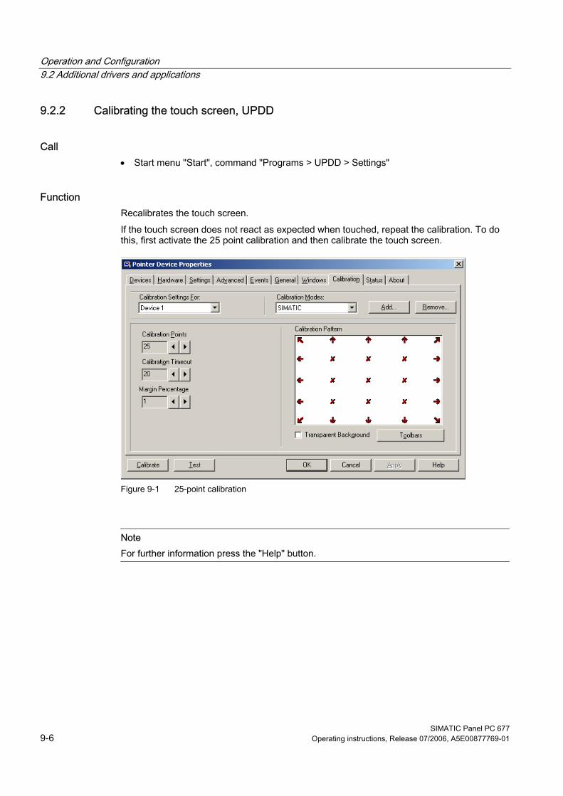
Operation and Configuration 9.2 Additional drivers and applications
SIMATIC Panel PC 677 9-6 Operating instructions, Release 07/2006, A5E00877769-01
9.2.2 Calibrating the touch screen, UPDD
Call • Start menu "Start", command "Programs > UPDD > Settings"
Function Recalibrates the touch screen. If the touch screen does not react as expected when touched, repeat the calibration. To do this, first activate the 25 point calibration and then calibrate the touch screen.
Figure 9-1 25-point calibration
Note For further information press the "Help" button.
Operation and Configuration 9.2 Additional drivers and applications
SIMATIC Panel PC 677 Operating instructions, Release 07/2006, A5E00877769-01 9-7
Warning Maloperation If you touch the touch screen while the screen saver is active, the SIMATIC process visualization software, e.g. WinCC, will carry out the functions which happen to be behind it.
Caution Only touch one point on the touch screen and not several points at one time. You may otherwise trigger unintended reactions. Do not touch the screen in the following situations: — When the device is booting until the boot process is completed — When plugging or unplugging USB components — While Scandisk is running
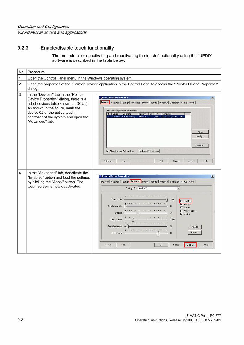
Operation and Configuration 9.2 Additional drivers and applications
SIMATIC Panel PC 677 9-8 Operating instructions, Release 07/2006, A5E00877769-01
9.2.3 Enable/disable touch functionality The procedure for deactivating and reactivating the touch functionality using the "UPDD" software is described in the table below.
No. Procedure 1 Open the Control Panel menu in the Windows operating system 2 Open the properties of the "Pointer Device" application in the Control Panel to access the "Pointer Device Properties"
dialog. 3 In the "Devices" tab in the "Pointer
Device Properties" dialog, there is a list of devices (also known as DCUs). As shown in the figure, mark the device 02 or the active touch controller of the system and open the "Advanced" tab.
4 In the "Advanced" tab, deactivate the "Enabled" option and load the settings by clicking the "Apply" button. The touch screen is now deactivated.
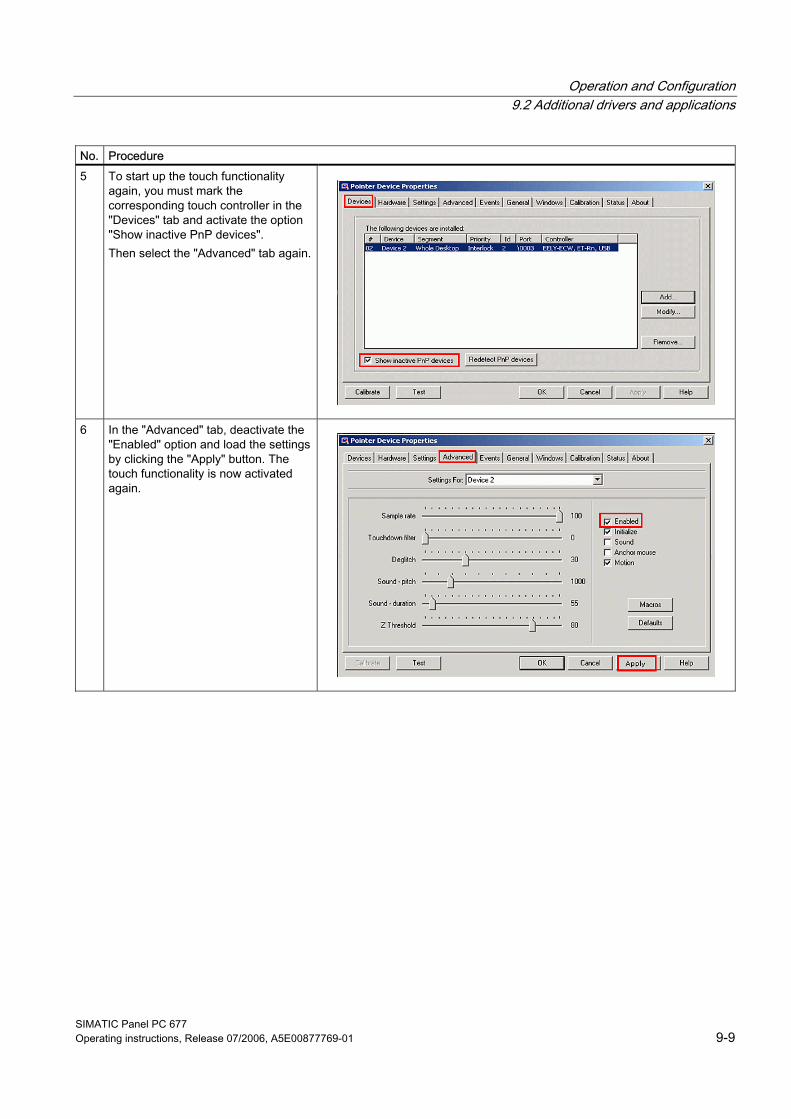
Operation and Configuration 9.2 Additional drivers and applications
SIMATIC Panel PC 677 Operating instructions, Release 07/2006, A5E00877769-01 9-9
No. Procedure 5 To start up the touch functionality
again, you must mark the corresponding touch controller in the "Devices" tab and activate the option "Show inactive PnP devices". Then select the "Advanced" tab again.
6 In the "Advanced" tab, deactivate the "Enabled" option and load the settings by clicking the "Apply" button. The touch functionality is now activated again.
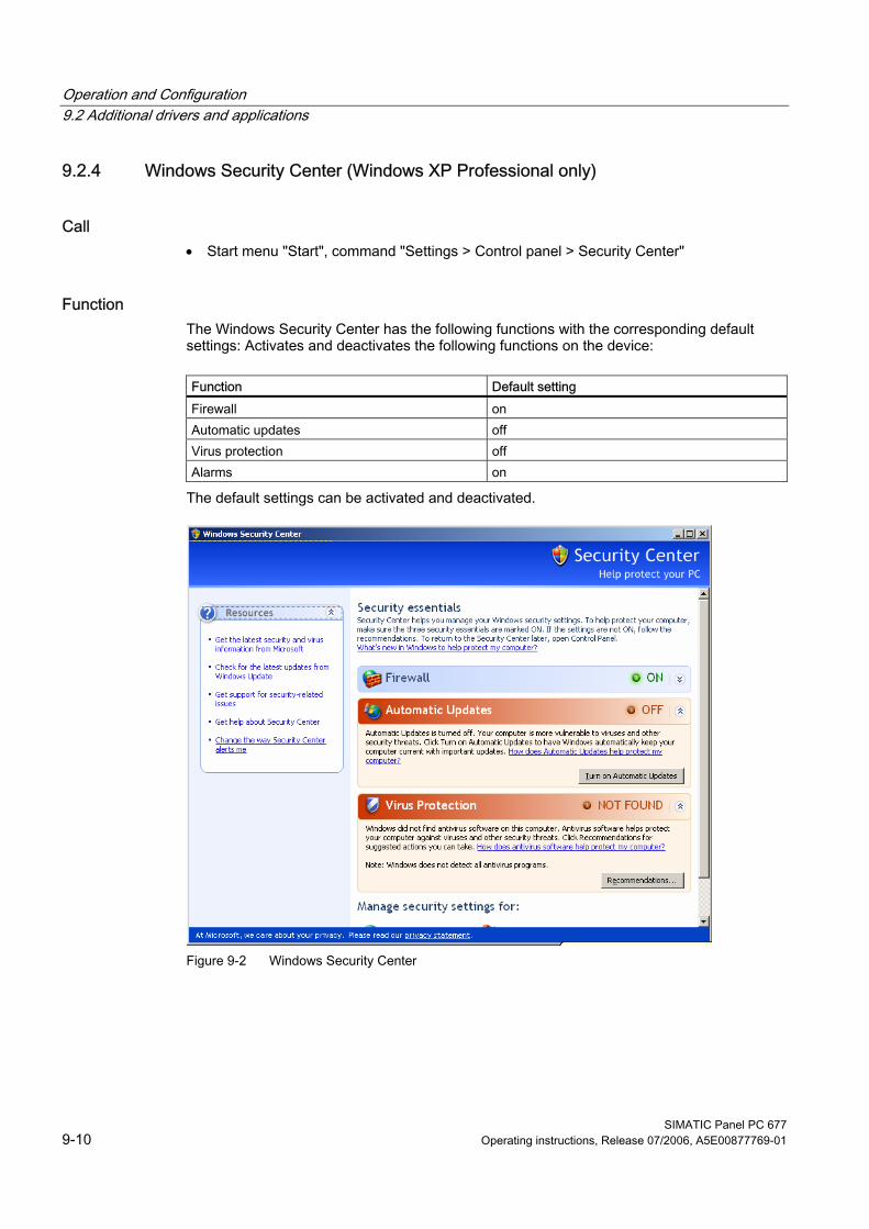
Operation and Configuration 9.2 Additional drivers and applications
SIMATIC Panel PC 677 9-10 Operating instructions, Release 07/2006, A5E00877769-01
9.2.4 Windows Security Center (Windows XP Professional only)
Call • Start menu "Start", command "Settings > Control panel > Security Center"
Function The Windows Security Center has the following functions with the corresponding default settings: Activates and deactivates the following functions on the device:
Function Default setting Firewall on Automatic updates off Virus protection off Alarms on
The default settings can be activated and deactivated.
Figure 9-2 Windows Security Center
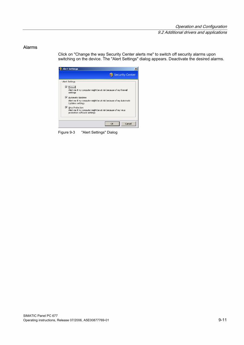
Operation and Configuration 9.2 Additional drivers and applications
SIMATIC Panel PC 677 Operating instructions, Release 07/2006, A5E00877769-01 9-11
Alarms Click on "Change the way Security Center alerts me" to switch off security alarms upon switching on the device. The "Alert Settings" dialog appears. Deactivate the desired alarms.
Figure 9-3 "Alert Settings" Dialog
Operation and Configuration 9.2 Additional drivers and applications
SIMATIC Panel PC 677 9-12 Operating instructions, Release 07/2006, A5E00877769-01
9.2.5 KeyTools (for key panel devices only) SIMATIC KeyTools is one selection of the applications for your Panel PC. These applications allow you to adapt key codes that are sent by the key panel of the control unit. SIMATIC KeyTools consists of the following applications: • Key code table: Loading and editing of key code tables • WinCC hotkey function: WinCC hotkey function activation and deactivation • Security features: Lock function that prevents two function keys from being activated
simultaneously. This prevents incorrect operations and undefined states of the user program.
Note For a detailed description of the SIMATIC KeyTools please refer to the help menu and the application description on the "Documentation and Drivers" CD.
Calling up KeyTools 1. Call KeyTools using the "Start" menu and command "Settings > Control Panel > SIMATIC KeyTools" 2. Select the desired application and follow the instructions on the screen.
Notice Malfunctions of the user software For security reasons always use the "Security features". If you deactivate it nevertheless, serious malfunctions of the user software may occur when the additional function keys and softkeys F11 to F20 and S1 to S16 are used or if own key code tables are used.
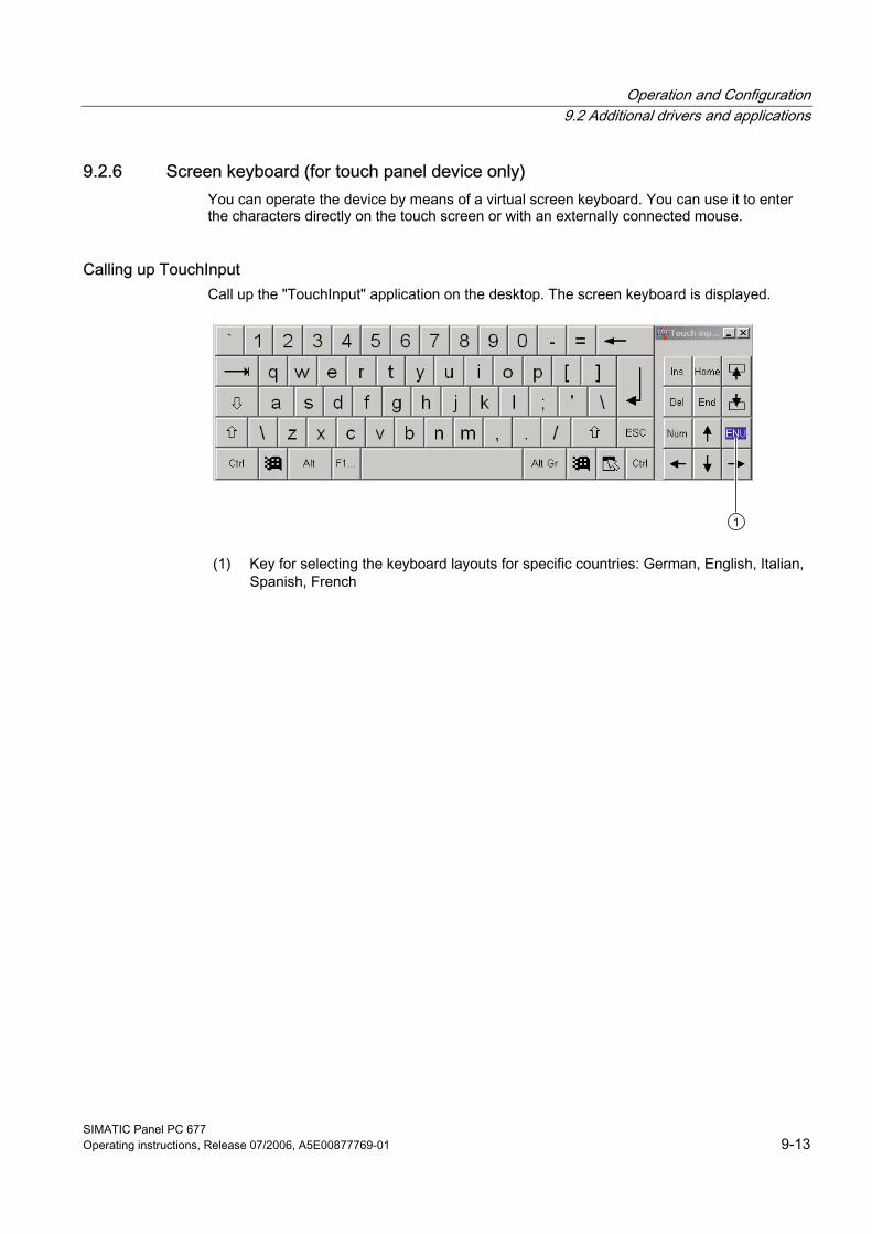
Operation and Configuration 9.2 Additional drivers and applications
SIMATIC Panel PC 677 Operating instructions, Release 07/2006, A5E00877769-01 9-13
9.2.6 Screen keyboard (for touch panel device only) You can operate the device by means of a virtual screen keyboard. You can use it to enter the characters directly on the touch screen or with an externally connected mouse.
Calling up TouchInput Call up the "TouchInput" application on the desktop. The screen keyboard is displayed.
(1) Key for selecting the keyboard layouts for specific countries: German, English, Italian, Spanish, French
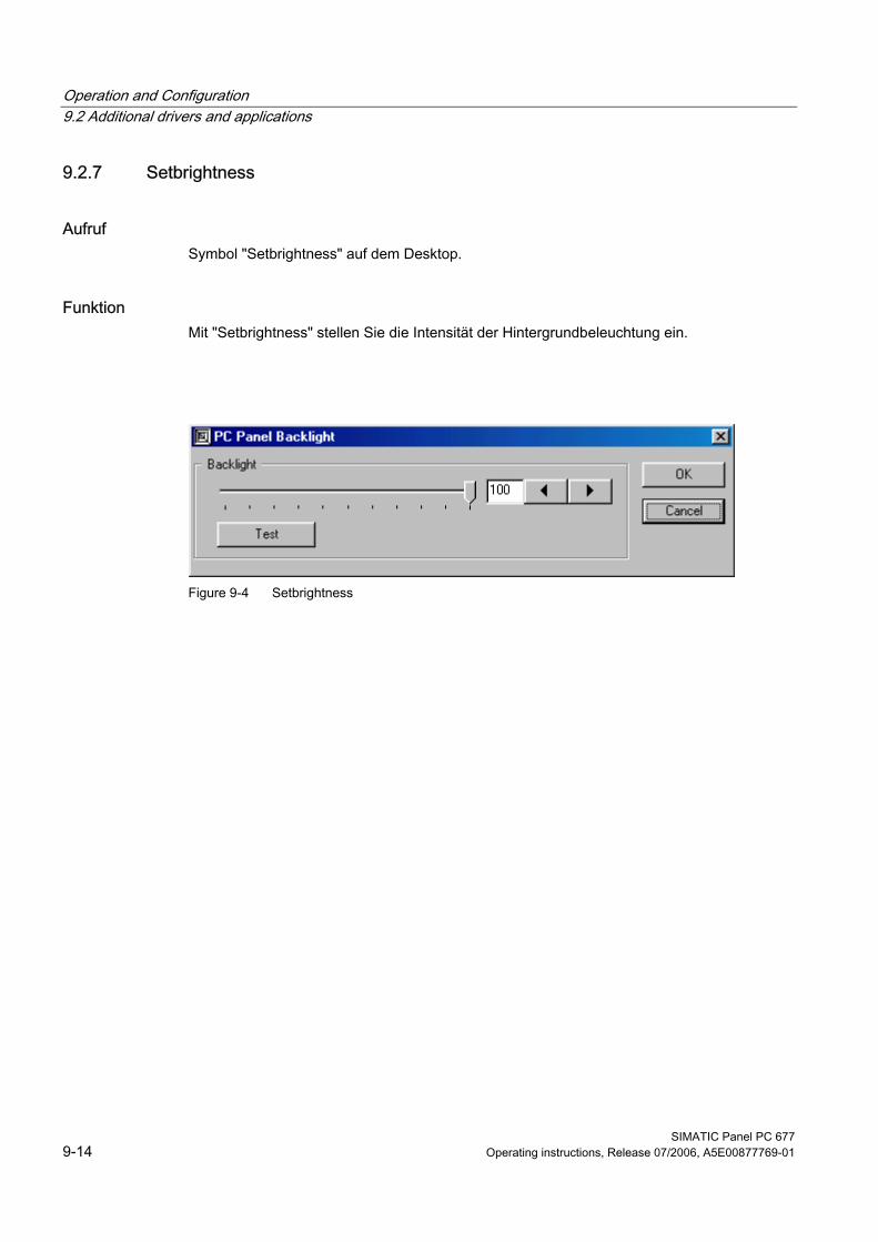
Operation and Configuration 9.2 Additional drivers and applications
SIMATIC Panel PC 677 9-14 Operating instructions, Release 07/2006, A5E00877769-01
9.2.7 Setbrightness
Aufruf Symbol "Setbrightness" auf dem Desktop.
Funktion Mit "Setbrightness" stellen Sie die Intensität der Hintergrundbeleuchtung ein.
Figure 9-4 Setbrightness
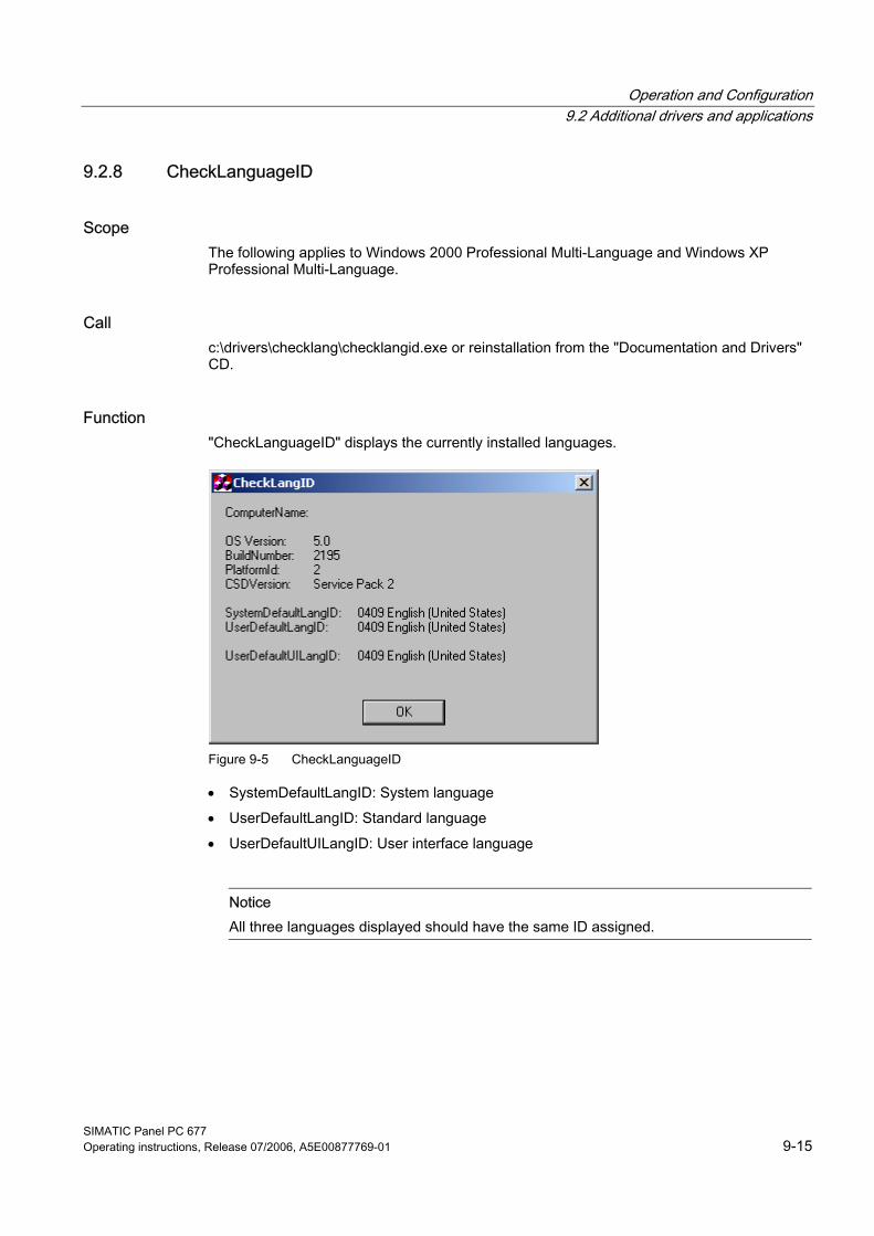
Operation and Configuration 9.2 Additional drivers and applications
SIMATIC Panel PC 677 Operating instructions, Release 07/2006, A5E00877769-01 9-15
9.2.8 CheckLanguageID
Scope The following applies to Windows 2000 Professional Multi-Language and Windows XP Professional Multi-Language.
Call c:\drivers\checklang\checklangid.exe or reinstallation from the "Documentation and Drivers" CD.
Function "CheckLanguageID" displays the currently installed languages.
Figure 9-5 CheckLanguageID
• SystemDefaultLangID: System language • UserDefaultLangID: Standard language • UserDefaultUILangID: User interface language
Notice All three languages displayed should have the same ID assigned.
Operation and Configuration 9.2 Additional drivers and applications
SIMATIC Panel PC 677 9-16 Operating instructions, Release 07/2006, A5E00877769-01
9.2.9 Multilingual settings for the operating system Windows MultiLanguage MUI operating system enables users to set the language of the GUI to their individual preference. Some elements are not localized, however, and remain in the original language of the system - English. You should therefore always install English language service packs. Further information about the language of the GUI, regional settings and inputs is available in the Internet at http://support.microsoft.com.
Setting up the language selection for Windows 2000 Professional The Multilanguage User Interface (MUI) allows you to set up the Windows 2000 Professional menus and dialogs for additional languages. To set the required languages for the Windows 2000 Professional menus, dialogs and keyboard layout, select:
Start > Settings > Control Panel > Regional Options > General tab, Setting for current user field and Language settings for the system field and the Keyboard layout field in the Input locales tab.
In addition to the menu and dialog language settings, you also need to set the default language by selecting Set Default... from the Regional Options dialog box. The default language setting of your Windows 2000 Professional installation is English and a US keyboard layout. To change to another language and keyboard layout, open the Control Panel and select:
Start > Settings > Control Panel > Regional Options >General tab, Setting for current user field and Language settings for the system field and the Input language field in the Input Locales tab.
Setting up the language selection for Windows XP Professional The Multilanguage User Interface (MUI) allows you to set up the Windows XP Professional menus and dialogs for additional languages. Default language of your Windows XP Professional MUI installation is English and a US keyboard layout. You can change the language in the Control Panel. Select:
Start > Control Panel > Date, Time, Language, and Regional Options > Add other languages > Languages tab,Language used in menus and dialogs field.
For the Date, Time, Language and Regional Options set the default as non-Unicode programs under Advanced in addition to the language for menus and dialogs.
Operation and Configuration 9.2 Additional drivers and applications
SIMATIC Panel PC 677 Operating instructions, Release 07/2006, A5E00877769-01 9-17
9.2.10 DVD ROM/CD RW
The DVD-ROM/CD-RW drive is an optional feature. Recording methods supported by the disk drive: Disc at once, Track at once, Session at once, Packet writing, whereby Disc at once und Track at once are recommended due to their compatibility to other optical drives. DVD-ROM, CD-ROM, CD-R and Video CDs can be read.
Burner/DVD player software To utilize the full functionality of our DVD-ROM/CD-RW drive, you need to install additional software (burning or DVD player software). This software is included on the CD supplied with the device. Insert the CD in the drive, run setup and follow the instructions on the screen.
Information on burning CD-Rs/CD-RWs
Caution Data may be corrupted when burning CD-R or CD-RW! Burning is permissible only in an undisturbed environment, i.e. shock and vibration stress must be avoided. Because of heavy fluctuation in the quality of CD-Rs, data may be corrupted in a burning session, even if no error message is initially displayed. The written data can only be verified by comparing these with the source. To be on the safe side, data should be verified after every burning session. When backing up an image, the data should be restored to the hard disk and the system should be rebooted from the hard disk.
Operation and Configuration 9.2 Additional drivers and applications
SIMATIC Panel PC 677 9-18 Operating instructions, Release 07/2006, A5E00877769-01
9.2.11 USB keyboard controller The USB keyboard controller supports the following additional functions for key models: • Keyboard programming with the "KeyTools" application • Adjustment of the backlighting brightness with the application "SetBrightness." • Control of the key LEDs The USB keyboard controller must be installed before this function can be used. For installation instructions, see the description on the "Documentation and Drivers" CD.
SIMATIC Panel PC 677 Operating instructions, Release 07/2006, A5E00877769-01 10-1
Operating 1010.1 10.1 Status displays
The two LEDs on the upper left hand side of the front panel display the operating status: • LED "POWER" green: Active voltage • LED "TEMP" orange: The temperature threshold has been exceeded; the maximum value
is preset and cannot be changed. Refer to the "Functions" chapter for more information.
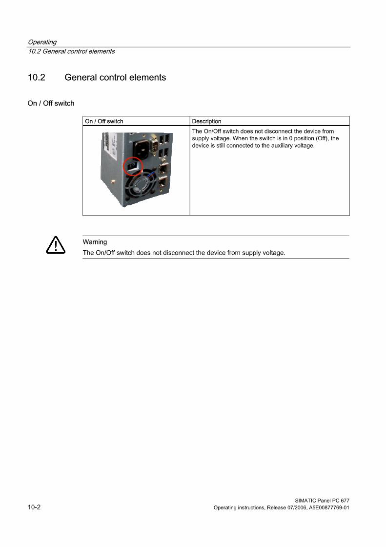
Operating 10.2 General control elements
SIMATIC Panel PC 677 10-2 Operating instructions, Release 07/2006, A5E00877769-01
10.2 10.2 General control elements
On / Off switch
On / Off switch Description
The On/Off switch does not disconnect the device from supply voltage. When the switch is in 0 position (Off), the device is still connected to the auxiliary voltage.
Warning The On/Off switch does not disconnect the device from supply voltage.
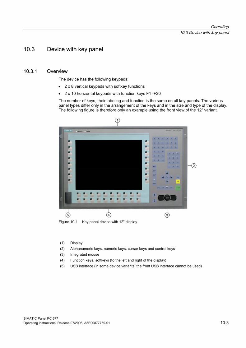
Operating 10.3 Device with key panel
SIMATIC Panel PC 677 Operating instructions, Release 07/2006, A5E00877769-01 10-3
10.3 10.3 Device with key panel
10.3.1 Overview The device has the following keypads: • 2 x 8 vertical keypads with softkey functions • 2 x 10 horizontal keypads with function keys F1 -F20 The number of keys, their labeling and function is the same on all key panels. The various panel types differ only in the arrangement of the keys and in the size and type of the display. The following figure is therefore only an example using the front view of the 12" variant.
Figure 10-1 Key panel device with 12" display
(1) Display (2) Alphanumeric keys, numeric keys, cursor keys and control keys (3) Integrated mouse (4) Function keys, softkeys (to the left and right of the display) (5) USB interface (in some device variants, the front USB interface cannot be used)
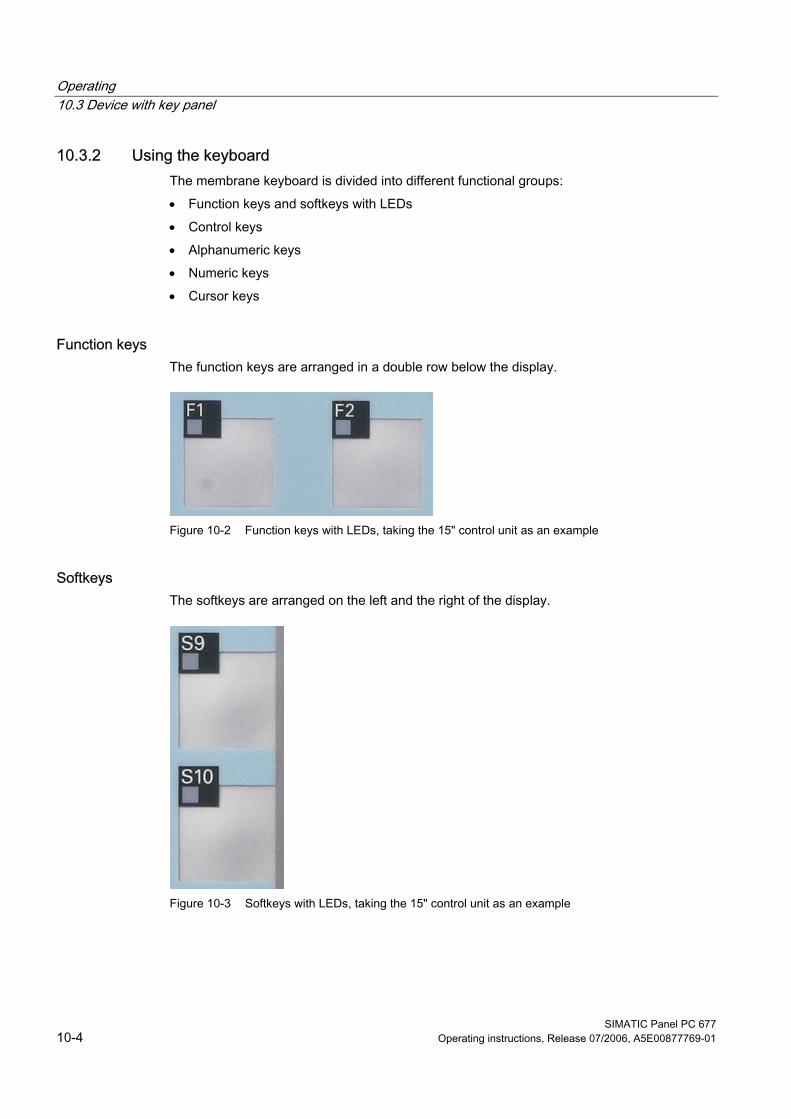
Operating 10.3 Device with key panel
SIMATIC Panel PC 677 10-4 Operating instructions, Release 07/2006, A5E00877769-01
10.3.2 Using the keyboard The membrane keyboard is divided into different functional groups: • Function keys and softkeys with LEDs • Control keys • Alphanumeric keys • Numeric keys • Cursor keys
Function keys The function keys are arranged in a double row below the display.
Figure 10-2 Function keys with LEDs, taking the 15" control unit as an example
Softkeys The softkeys are arranged on the left and the right of the display.
Figure 10-3 Softkeys with LEDs, taking the 15" control unit as an example
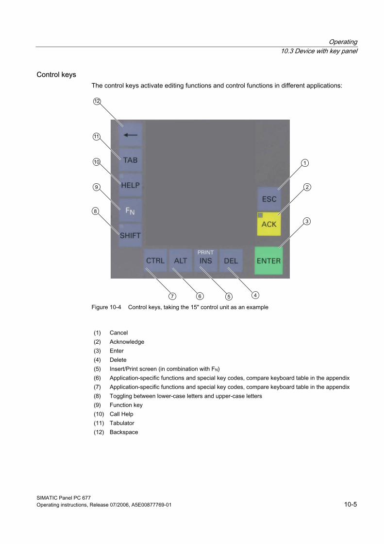
Operating 10.3 Device with key panel
SIMATIC Panel PC 677 Operating instructions, Release 07/2006, A5E00877769-01 10-5
Control keys The control keys activate editing functions and control functions in different applications:
Figure 10-4 Control keys, taking the 15" control unit as an example
(1) Cancel (2) Acknowledge (3) Enter (4) Delete (5) Insert/Print screen (in combination with FN) (6) Application-specific functions and special key codes, compare keyboard table in the appendix (7) Application-specific functions and special key codes, compare keyboard table in the appendix (8) Toggling between lower-case letters and upper-case letters (9) Function key (10) Call Help (11) Tabulator (12) Backspace
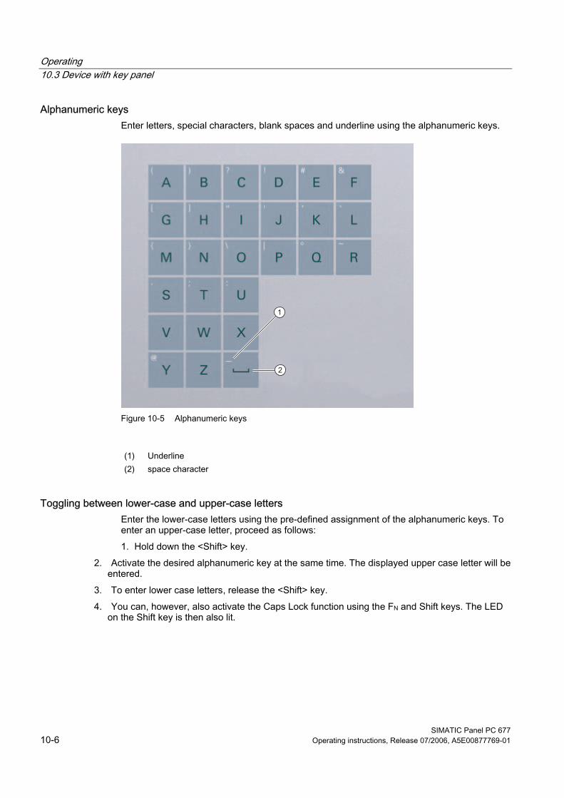
Operating 10.3 Device with key panel
SIMATIC Panel PC 677 10-6 Operating instructions, Release 07/2006, A5E00877769-01
Alphanumeric keys Enter letters, special characters, blank spaces and underline using the alphanumeric keys.
Figure 10-5 Alphanumeric keys
(1) Underline (2) space character
Toggling between lower-case and upper-case letters Enter the lower-case letters using the pre-defined assignment of the alphanumeric keys. To enter an upper-case letter, proceed as follows: 1. Hold down the <Shift> key.
2. Activate the desired alphanumeric key at the same time. The displayed upper case letter will be entered.
3. To enter lower case letters, release the <Shift> key. 4. You can, however, also activate the Caps Lock function using the FN and Shift keys. The LED
on the Shift key is then also lit.
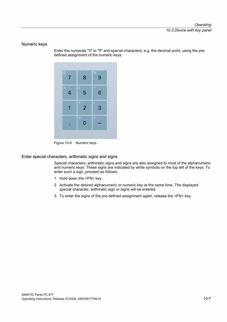
Operating 10.3 Device with key panel
SIMATIC Panel PC 677 Operating instructions, Release 07/2006, A5E00877769-01 10-7
Numeric keys Enter the numerals "0" to "9" and special characters, e.g. the decimal point, using the pre-defined assignment of the numeric keys.
Figure 10-6 Numeric keys
Enter special characters, arithmetic signs and signs Special characters, arithmetic signs and signs are also assigned to most of the alphanumeric and numeric keys. These signs are indicated by white symbols on the top left of the keys. To enter such a sign, proceed as follows: 1. Hold down the <FN> key. 2. Activate the desired alphanumeric or numeric key at the same time. The displayed
special character, arithmetic sign or signs will be entered. 3. To enter the signs of the pre-defined assignment again, release the <FN> key.
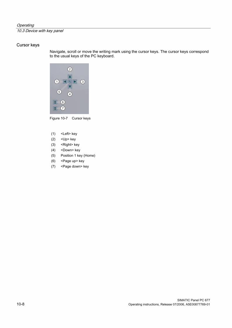
Operating 10.3 Device with key panel
SIMATIC Panel PC 677 10-8 Operating instructions, Release 07/2006, A5E00877769-01
Cursor keys Navigate, scroll or move the writing mark using the cursor keys. The cursor keys correspond to the usual keys of the PC keyboard.
Figure 10-7 Cursor keys
(1) <Left> key (2) <Up> key (3) <Right> key (4) <Down> key (5) Position 1 key (Home) (6) <Page up> key (7) <Page down> key
Operating 10.3 Device with key panel
SIMATIC Panel PC 677 Operating instructions, Release 07/2006, A5E00877769-01 10-9
External keyboards The keyboard layout has been set to "English/USA international." If you use a keyboard with a layout other than the "English/USA international" layout, the key codes of the internal and external keyboards might no longer correspond.
Notice Maloperation If you activate several keys simultaneously, a malfunction on the device cannot be excluded. Activate function keys and softkeys only in sequence!
Notice Malfunctions of the user software For security reasons, always use "Security features" of the KeyTools. If you deactivate it nevertheless, serious malfunctions of the user software may occur when the additional function keys and softkeys F13 to S16 are used or if own key code tables are used.
Notice Risk of damage Activating a key using a hard or pointed object, e.g. a screwdriver, reduces the life of the key or can damage it.
Operating 10.3 Device with key panel
SIMATIC Panel PC 677 10-10 Operating instructions, Release 07/2006, A5E00877769-01
10.3.3 Using the direct control key module The direct control key module is a module that is intended for use with the SIMATIC Panel PC 677 (exclusively for variants with an integral membrane keyboard). Digital events can be assigned to the function keys and softkeys (F1-F20 and S1-S16) of the membrane keyboard via this module. This means that a digital input of a PLC can be activated at the press of a key over PROFIBUS. The module is implemented as a PROFIBUS DP slave.
Functionality The direct control key module is used to expand the functional scope of the SIMATIC Panel PC 677 with the following features: • Up to 32 function keys/softkeys on the membrane keyboard of the Panel PC can be
scanned over PROFIBUS as direct keys. • Up to 16 additional keys from an external operator panel can be connected if required. • There are 16 digital outputs for activating checkback signal lamps (by the PLC over
PROFIBUS DP) in external operator panels. All direct control keys can be scanned over PROFIBUS DP from the PLC.
Software control At the Panel PC end, the direct control keys are programmed using the "Key pad" software tool. The codes for all keys of the Panel PC 677 can be changed using this tool. Furthermore, direct key functions can be assigned to all function and control keys. As of start of delivery, the Key-Pad software is supplied on diskette with the direct control key module and on the Documentation and Drivers CD with all Panel PC 677.
Assembly The direct control key module can be ordered separately from the Panel PC. It can be retrofitted in the immediate vicinity of the Panel PC: Either on a standard mounting rail (the mounting equipment required is included in the package with the direct control key module) or directly using 4 screws on a wall /front panel / control panel. Detailed mounting instructions are included with every direct control key module on paper and with every Panel PC 677 on the "Documentation & Drivers" CD.
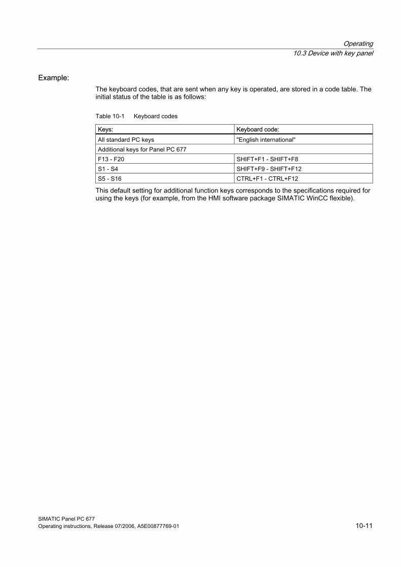
Operating 10.3 Device with key panel
SIMATIC Panel PC 677 Operating instructions, Release 07/2006, A5E00877769-01 10-11
Example: The keyboard codes, that are sent when any key is operated, are stored in a code table. The initial status of the table is as follows:
Table 10-1 Keyboard codes
Keys: Keyboard code: All standard PC keys "English international" Additional keys for Panel PC 677 F13 - F20 SHIFT+F1 - SHIFT+F8 S1 - S4 SHIFT+F9 - SHIFT+F12 S5 - S16 CTRL+F1 - CTRL+F12
This default setting for additional function keys corresponds to the specifications required for using the keys (for example, from the HMI software package SIMATIC WinCC flexible).
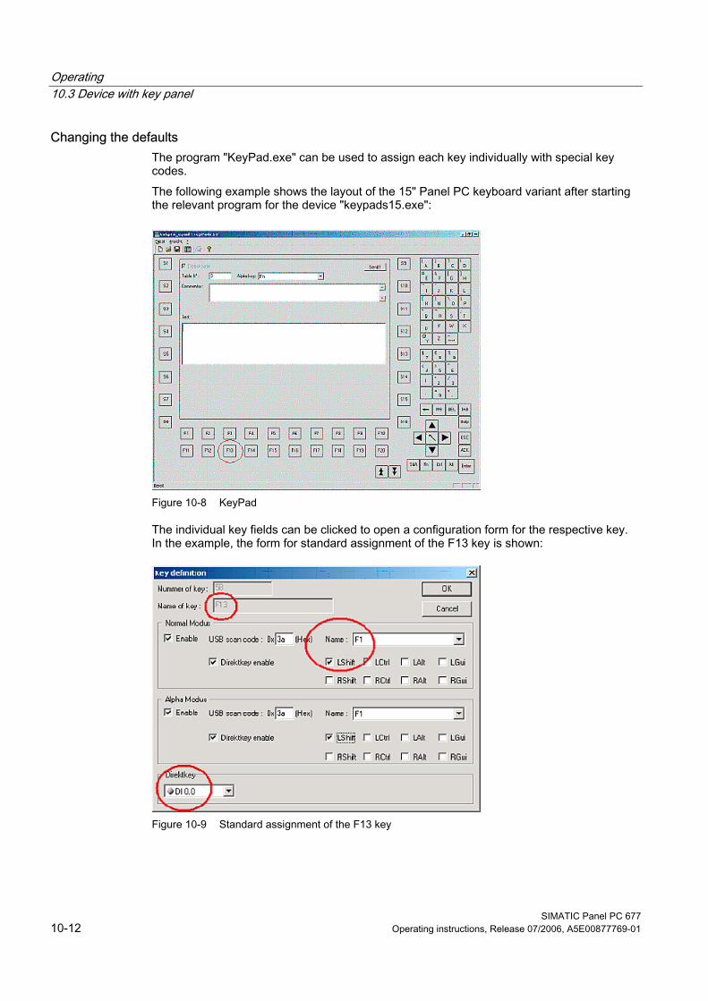
Operating 10.3 Device with key panel
SIMATIC Panel PC 677 10-12 Operating instructions, Release 07/2006, A5E00877769-01
Changing the defaults The program "KeyPad.exe" can be used to assign each key individually with special key codes. The following example shows the layout of the 15" Panel PC keyboard variant after starting the relevant program for the device "keypads15.exe":
Figure 10-8 KeyPad
The individual key fields can be clicked to open a configuration form for the respective key. In the example, the form for standard assignment of the F13 key is shown:
Figure 10-9 Standard assignment of the F13 key
Operating 10.3 Device with key panel
SIMATIC Panel PC 677 Operating instructions, Release 07/2006, A5E00877769-01 10-13
Explanation: The key labelled F13 outputs the key code LSHIFT+F1 and sets digital input DI 0.0 when the direct key module is used. For further information about using the tool, visit the Internet page http://www.siemens.com/asis. Search here under "Download" using the term "Keypad". The self-unpacking file F_KEY_Total.exe contains extensive information (description in English and German, examples) on using the additional function keys of the Panel PC 677.
Operating 10.3 Device with key panel
SIMATIC Panel PC 677 10-14 Operating instructions, Release 07/2006, A5E00877769-01
10.3.4 Labelling function keys and softkeys
Area of application This section applies only to control units with key panels.
Introduction The control unit has two horizontal and two vertical keypads Assign user specific functions to the keys as needed. Label the keys with labelling strips from the options. DIN A4 film is available for the production and insertion of the labeling strips, as described in chapter 3 "Description".
Warning Labeling Label the function keys and softkeys to conform with the project. Labeling without reference to a project leads to incorrect operations on the system to be observed.
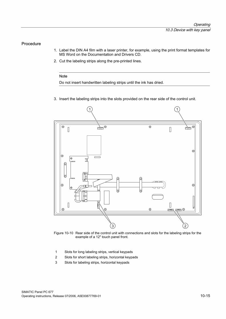
Operating 10.3 Device with key panel
SIMATIC Panel PC 677 Operating instructions, Release 07/2006, A5E00877769-01 10-15
Procedure 1. Label the DIN A4 film with a laser printer, for example, using the print format templates for
MS Word on the Documentation and Drivers CD. 2. Cut the labeling strips along the pre-printed lines.
Note Do not insert handwritten labeling strips until the ink has dried.
3. Insert the labeling strips into the slots provided on the rear side of the control unit.
Figure 10-10 Rear side of the control unit with connections and slots for the labeling strips for the
example of a 12" touch panel front.
1 Slots for long labeling strips, vertical keypads 2 Slots for short labeling strips, horizontal keypads 3 Slots for labeling strips, horizontal keypads
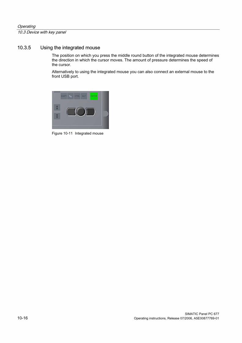
Operating 10.3 Device with key panel
SIMATIC Panel PC 677 10-16 Operating instructions, Release 07/2006, A5E00877769-01
10.3.5 Using the integrated mouse The position on which you press the middle round button of the integrated mouse determines the direction in which the cursor moves. The amount of pressure determines the speed of the cursor. Alternatively to using the integrated mouse you can also connect an external mouse to the front USB port.
Figure 10-11 Integrated mouse
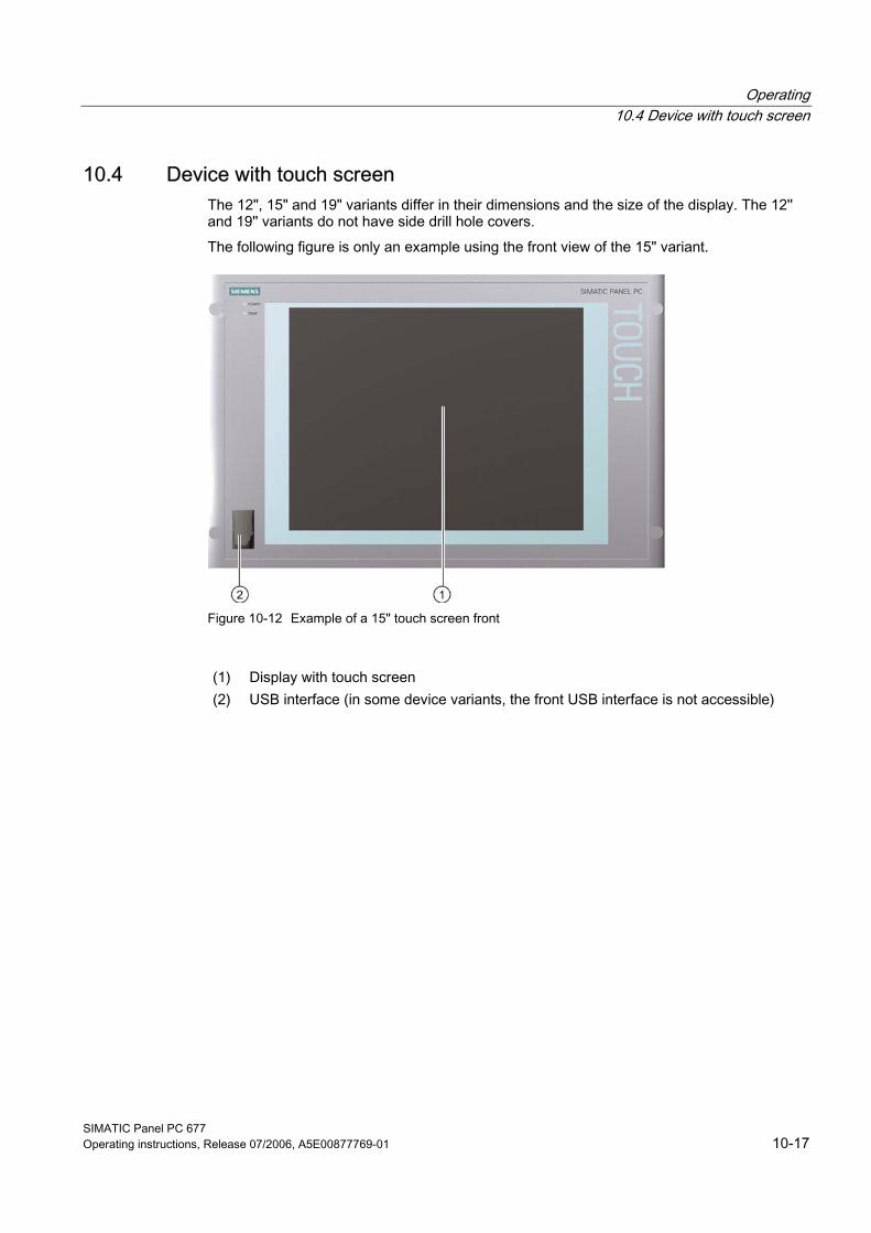
Operating 10.4 Device with touch screen
SIMATIC Panel PC 677 Operating instructions, Release 07/2006, A5E00877769-01 10-17
10.4 10.4 Device with touch screen The 12", 15" and 19" variants differ in their dimensions and the size of the display. The 12'' and 19'' variants do not have side drill hole covers. The following figure is only an example using the front view of the 15" variant.
Figure 10-12 Example of a 15" touch screen front
(1) Display with touch screen (2) USB interface (in some device variants, the front USB interface is not accessible)
Operating 10.4 Device with touch screen
SIMATIC Panel PC 677 10-18 Operating instructions, Release 07/2006, A5E00877769-01
10.4.1 Using the touch screen On the display that is touch-sensitive due to the touch sensor, application-specific user interface elements, for example buttons, are displayed. When you tap the command button with your finger, the function assigned to the button is activated. The following types of pressure are permissible: • Using a plastic pen with a 1 mm radius at the point: 25 g. • Using a silicone finger with a diameter of 1.6 cm: 50 g.
Caution Only touch one point on the touch screen and not several points at one time. You may otherwise trigger unintended reactions. Do not touch the screen in the following situations: - During the booting process - When plugging or unplugging USB components - While Scandisk is running
Notice Touching the touch screen with hard or pointed objects can damage the screen and thus impair its functionality. Only operate the touch screen with your fingers (even with gloves) or approved touch pens.
Operating 10.5 Transferring authorizations
SIMATIC Panel PC 677 Operating instructions, Release 07/2006, A5E00877769-01 10-19
10.5 10.5 Transferring authorizations
Note The device has no floppy disk drive. Therefore, where necessary, transfer the authorizations for SIMATIC HMI software from a USB floppy disk drive.
The following devices have been tested: SINUMERIK FLOPPY DISK DRIVE, order number 6FC5235-0AA05-1AA2
Caution The USB floppy disk drive is only suitable when mounted in a switchgear cabinet.

Operating 10.5 Transferring authorizations
SIMATIC Panel PC 677 10-20 Operating instructions, Release 07/2006, A5E00877769-01
SIMATIC Panel PC 677 Operating instructions, Release 07/2006, A5E00877769-01 11-1
Functions 1111.1 11.1 Overview
The following individual functions are implemented: • Temperature monitoring and over/under temperature indication • Watchdog • Fan monitoring Messages can be output from the monitoring modules to the applications. The SOM software (Safecard On Motherboard) and DiagMonitor software are provided on the devices for this. The "DiagMonitor Software" CD contains the monitoring software, the software for the stations to be monitored, and a library for creating user-specific applications. The DiagMonitor software can be ordered as an accessory with a separate order number. The description of the driver and the SOM program are available on the "Documentation and Drivers" CD.
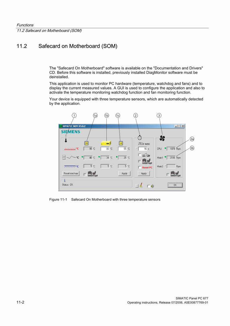
Functions 11.2 Safecard on Motherboard (SOM)
SIMATIC Panel PC 677 11-2 Operating instructions, Release 07/2006, A5E00877769-01
11.2 11.2 Safecard on Motherboard (SOM)
The "Safecard On Motherboard" software is available on the "Documentation and Drivers" CD. Before this software is installed, previously installed DiagMonitor software must be deinstalled. This application is used to monitor PC hardware (temperature, watchdog and fans) and to display the current measured values. A GUI is used to configure the application and also to activate the temperature monitoring watchdog function and fan monitoring function. Your device is equipped with three temperature sensors, which are automatically detected by the application.
Figure 11-1 Safecard On Motherboard with three temperature sensors
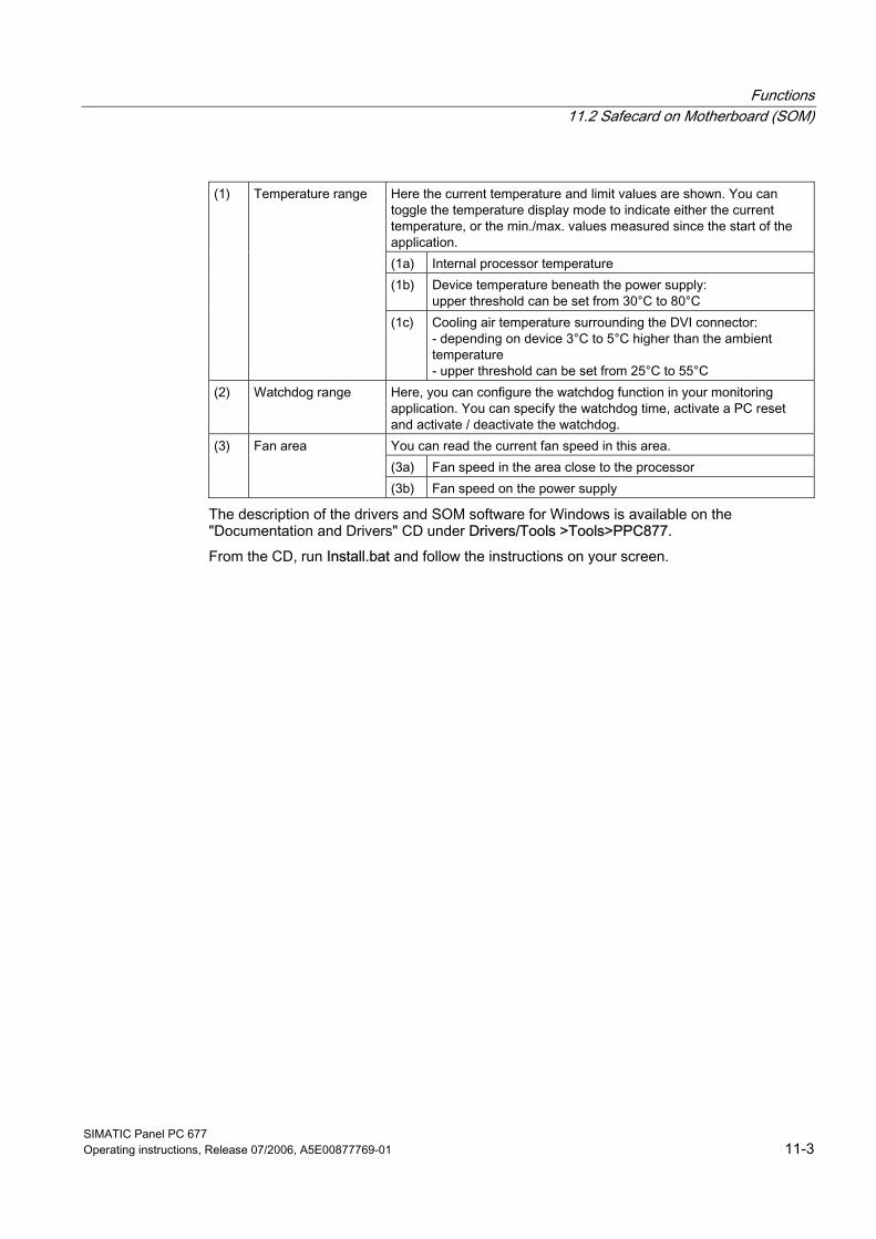
Functions 11.2 Safecard on Motherboard (SOM)
SIMATIC Panel PC 677 Operating instructions, Release 07/2006, A5E00877769-01 11-3
Here the current temperature and limit values are shown. You can toggle the temperature display mode to indicate either the current temperature, or the min./max. values measured since the start of the application. (1a) Internal processor temperature (1b) Device temperature beneath the power supply:
upper threshold can be set from 30°C to 80°C
(1) Temperature range
(1c) Cooling air temperature surrounding the DVI connector: - depending on device 3°C to 5°C higher than the ambient temperature - upper threshold can be set from 25°C to 55°C
(2) Watchdog range Here, you can configure the watchdog function in your monitoring application. You can specify the watchdog time, activate a PC reset and activate / deactivate the watchdog. You can read the current fan speed in this area. (3a) Fan speed in the area close to the processor
(3) Fan area
(3b) Fan speed on the power supply
The description of the drivers and SOM software for Windows is available on the "Documentation and Drivers" CD under Drivers/Tools >Tools>PPC877. From the CD, run Install.bat and follow the instructions on your screen.
Functions 11.3 Temperature monitoring
SIMATIC Panel PC 677 11-4 Operating instructions, Release 07/2006, A5E00877769-01
11.3 11.3 Temperature monitoring
Temperature monitoring The temperature is recorded by means of three thermocouples. One thermocouple monitors the processor temperature, another the temperature in the area near the power supply, and a third the air intake temperature next to the DVI interface. When the temperature is out of the range of one of the three set temperature thresholds, the following error reactions are triggered:
Response Option Device and CPU fans accelerate to maximum speed.
None
SOM or DiagMonitor software is activated None
The temperature error is retained until the temperatures have fallen below the thresholds and are reset by one of the following measures: • Error acknowledgement in the SOM program (manually by means of the broom icon) • Restart of the device.
Notice When an error occurs, the "TEMP" LED also illuminates with the status indicators.
Functions 11.4 Watchdog (WD)
SIMATIC Panel PC 677 Operating instructions, Release 07/2006, A5E00877769-01 11-5
11.4 11.4 Watchdog (WD)
Function The watchdog monitors the program execution and reports a program crash to the user by means of various reactions. The watchdog is idle when the PC is switched on or after a HW-RESET(cold restart), i.e., no reaction of the WD is triggered.
WD reactions If the WD is not triggered again within the set time (by driver or SOM program), the following reactions are initiated:
Response Option WD acknowledgement None Trigger a PC reset Configurable SOM or DiagMonitor software is activated None
WD monitor times (TWD) The TWD are adjustable in increments of one second in a range from 3 to 255 seconds.
Note If the watchdog time is changed after the watchdog was enabled (i.e., while the watchdog is running), the watchdog is retriggered!
Functions 11.5 Fan monitoring
SIMATIC Panel PC 677 11-6 Operating instructions, Release 07/2006, A5E00877769-01
11.5 11.5 Fan monitoring
The function monitors operation of the enclosure and power supply fans. When a fan fails, the following reactions are triggered:
Response Option SOM or DiagMonitor software is activated None
The temperature error is retained until the cause of the fan failure has been rectified and the error is reset in one of the following ways: • Acknowledgement of the error message by means of the SOM program • Restart of the device
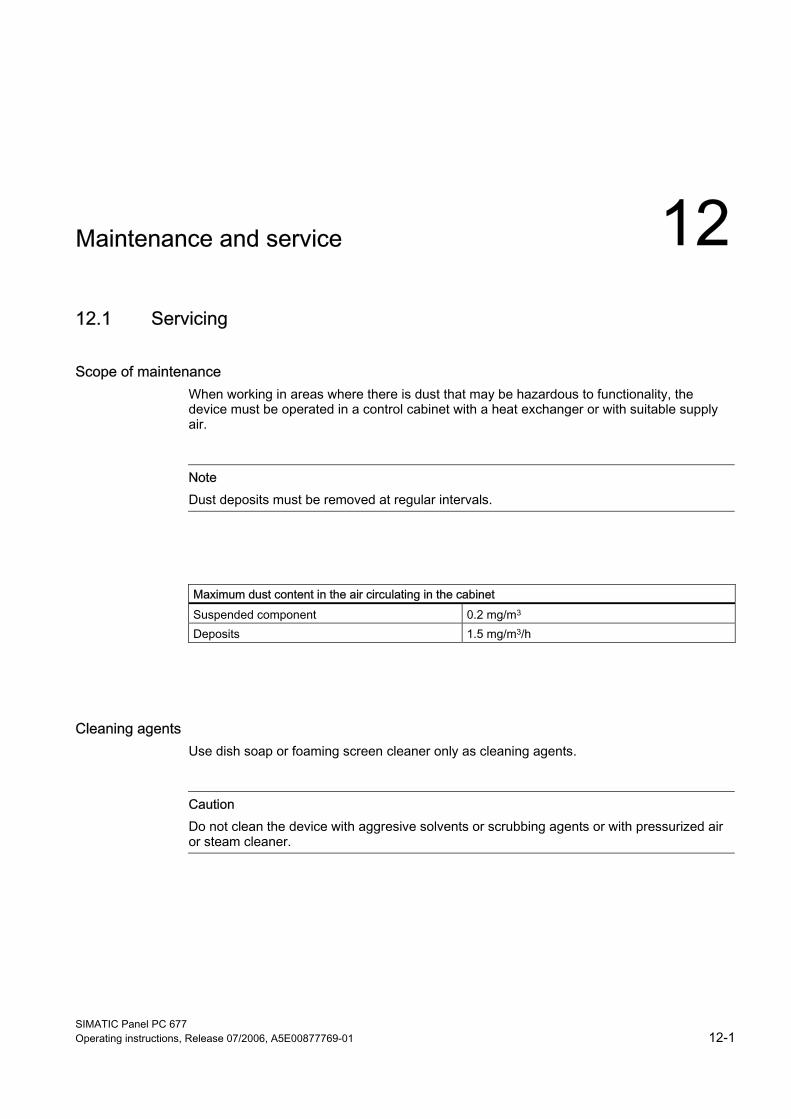
SIMATIC Panel PC 677 Operating instructions, Release 07/2006, A5E00877769-01 12-1
Maintenance and service 1212.1 12.1 Servicing
Scope of maintenance When working in areas where there is dust that may be hazardous to functionality, the device must be operated in a control cabinet with a heat exchanger or with suitable supply air.
Note Dust deposits must be removed at regular intervals.
Maximum dust content in the air circulating in the cabinet Suspended component 0.2 mg/m3 Deposits 1.5 mg/m3/h
Cleaning agents Use dish soap or foaming screen cleaner only as cleaning agents.
Caution Do not clean the device with aggresive solvents or scrubbing agents or with pressurized air or steam cleaner.
Maintenance and service 12.1 Servicing
SIMATIC Panel PC 677 12-2 Operating instructions, Release 07/2006, A5E00877769-01
Chemical stability
Caution Adhere to the information regarding chemical resistance of the panel front. Please go to http://www.siemens.com/asis under "Tools & Downloads" for more information. Enter the article ID 16532108 as the search term. The available articles are displayed.
Procedure for cleaning the device 1. Switch off the device. This prevents the accidental triggering of functions when the screen
is touched. 2. Dampen the cleaning cloth. 3. Spray the cleaning agent on the cloth and not directly on the device. 4. Clean the device with the cleaning cloth.
Maintenance and service 12.2 Maintenance and care of devices with stainless steel front
SIMATIC Panel PC 677 Operating instructions, Release 07/2006, A5E00877769-01 12-3
12.2 12.2 Maintenance and care of devices with stainless steel front
Scope of maintenance The device is designed for low-maintenance operation. You should nonetheless clean the screen and the control panel at regular intervals. These measures and proper handling of the device increase the useful life of the front membrane and of the stainless steel front panel.
General information on cleaning
Caution Do not clean the device using aggressive cleaners or detergents, greasing or abrasive detergents, concentrated acids or caustic solutions, leather, scratching or rough rags and equipment. For further information, refer to the section "Chemical resistance." Do not clean the device with chlorine or chloride, for example, active chlorine, with laser or ultrasonic equipment, or with cardice. You damage the control panel if you clean it with high pressure equipment. Do not clean the device thermally, for example, using hot steam equipment, because this would inevitably damage the control panel and, in particular, the touch sensor system.
The front panel is protected in accordance with the degree of protection against the ingress of water which is directed towards the device at a defined jet force. Observe the permitted ambient temperatures. For additional information, refer to the chapters: • Application planning, Section Mounting positions and fastening • Technical data, Section General technical data and Permissible temperature ranges
depending on the type of installation
Cleaning the front membrane Clean the front membrane using the equipment described below: • Soft, non-abrasive window wipers or a soft, clean rag • Rubber window wipers • Liquid glass cleaners • Kitchen or household paper For further information, refer to the section Chemical resistance of stainless steel fronts.
Cleaning the stainless steel front For information, refer to the section "Handling of stainless steel surfaces."
Maintenance and service 12.2 Maintenance and care of devices with stainless steel front
SIMATIC Panel PC 677 12-4 Operating instructions, Release 07/2006, A5E00877769-01
Procedure
Warning Always switch off the device before you clean it, or set it to a defined state, for example, by activating a cleaning screen. This avoids the risk of triggering unwanted functions when you touch the screen or when a water jet contacts the screen.
Caution Do not rub off the front membrane in dry state. Always avoid the return of food stuff splashes to the production process. Follow the general cleaning guidelines.
5. Switch off the device. When the system is in operation, you can also activate a cleaning screen on the touch screen.
6. Always dilute glass cleaners with water before you apply these. Use clean water. 7. Use a window wiper or a cloth to wipe off the front membrane. Work from top to bottom.
Rinse off the dirt particles when doing so. 8. Rinse the window wiper or cloth several times. 9. Clean the edges with a cloth or household paper. 10. Moisten the front membrane once again. 11. Strip off the moisture with the window wiper, working from top to bottom and without
leaving any streaks. After each pass, wipe off the window wiper with soft household paper. Wipe off any water accumulating on the bottom edge of the front membrane using soft household paper.
12. Wipe off the edges using household paper. 13. Clean the stainless steel surface with a neutral, alkaline cleaner or, if necessary, with a
caustic cleaner which does not contain active chlorine. For further information, refer to the section Handling of stainless steel surfaces.
Maintenance and service 12.3 Chemical resistance of stainless steel fronts
SIMATIC Panel PC 677 Operating instructions, Release 07/2006, A5E00877769-01 12-5
12.3 12.3 Chemical resistance of stainless steel fronts
Front membrane The resistance of the front membrane to various chemicals was tested to DIN 42 115, section 2. The front membrane is resistant to the chemicals listed below: • Alcohol • Diluted acids • Diluted caustic solutions • Ester • Hydrocarbons • Household cleaners
Maintenance and service 12.4 Handling of stainless steel surfaces
SIMATIC Panel PC 677 12-6 Operating instructions, Release 07/2006, A5E00877769-01
12.4 12.4 Handling of stainless steel surfaces
Resistance Information on the resistance of stainless steel: • The stainless steel surface is not fully resistant against the chemicals listed below:
– Hydrochloric acid – Sulphuric acid – Caustic soda – Chlorine – Chloride
Do not clean the stainless steel surface with these chemicals or with similar acids or caustic solutions. • Acid steam develops, for example, when tiles are cleaned with hydrochloric acid, and is
also harmful to the stainless steel. If the stainless steel parts are unintentionally contaminated with hydrochloric acid, rinse these off immediately with plenty of water.
• Clean the stainless steel surface with a neutral, alkaline cleaner or, if necessary, with a caustic cleaner which does not contain active chlorine.
Cleaning guidelines Further information on stainless steel surfaces: • The surface should be properly ventilated. • Keep the surface clean. Remove cleaners and food residue immediately. Always avoid
the return of food stuff splashes to the production process. • If mechanical cleaning is necessary, do not use cleaning equipment made of metal.
– Use brushes made of plastic or natural materials, or a microfiber pad. – Use plenty of water to clean the surface. – Remove cleaners without leaving any residue, including corners and confined areas.
• Make sure surface is not damaged: Do not damage the device during operation, or by cleaning or repairing it using hard tools, in particular tools made of corrosive materials.
• Avoid an contact of the surface with corrosive parts: Auxiliary rust of water lines, file chips, residue of wire brushes or steel wool and rust films have a corrosive effect on parts made of stainless steel. – Remove any stains or auxiliary rust immediately. – Remove new rust spots with a mild abrasive detergent in order to prevent any further
corrosion. – Rinse the part thoroughly after you cleaned it.
Maintenance and service 12.5 Spare parts
SIMATIC Panel PC 677 Operating instructions, Release 07/2006, A5E00877769-01 12-7
12.5 12.5 Spare parts The device has the following replacement parts:
Replacement part Order No. Key panel 12''-TFT 15''-TFT Touch panel 12''-TFT 15''-TFT 19''-TFT
6AV7672-1AB00-0AA0 6AV7672-1AD00-0AA0 6AV7672-1AA00-0AA0 6AV7672-1AC00-0AA0 6AV7672-1AE00-0AA0
Key front, without front USB interface*) 12'' TFT 15'' TFT Touch front, without front USB interface*) 12'' TFT 15'' TFT 19'' TFT
6AV7672-1AB10-0AA0 6AV7672-1AD10-0AA0 6AV7672-1AA10-0AA0 6AV7672-1AC10-0AA0 6AV7672-1AE10-0AA0
Set of clamps 6FC5248-0AF06-0AA0 Plastic cap USB interface A5E00378392 Lithium battery A5E00331143
*) For more information, please refer to the chapter "Description." Use only Siemens spare parts or spare parts released by Siemens, otherwise the warranty, CE declaration of conformity and UL approval will be invalidated.
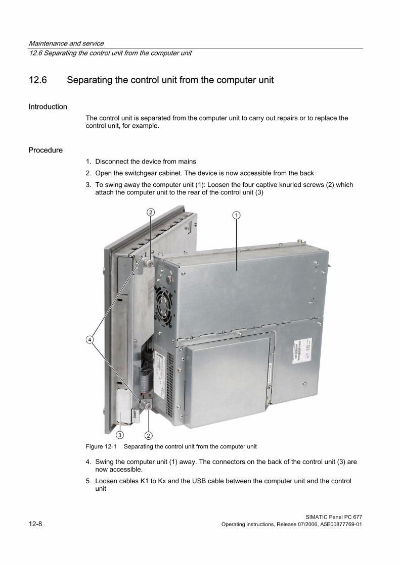
Maintenance and service 12.6 Separating the control unit from the computer unit
SIMATIC Panel PC 677 12-8 Operating instructions, Release 07/2006, A5E00877769-01
12.6 12.6 Separating the control unit from the computer unit
Introduction The control unit is separated from the computer unit to carry out repairs or to replace the control unit, for example.
Procedure 1. Disconnect the device from mains 2. Open the switchgear cabinet. The device is now accessible from the back 3. To swing away the computer unit (1): Loosen the four captive knurled screws (2) which
attach the computer unit to the rear of the control unit (3)
Figure 12-1 Separating the control unit from the computer unit
4. Swing the computer unit (1) away. The connectors on the back of the control unit (3) are now accessible.
5. Loosen cables K1 to Kx and the USB cable between the computer unit and the control unit
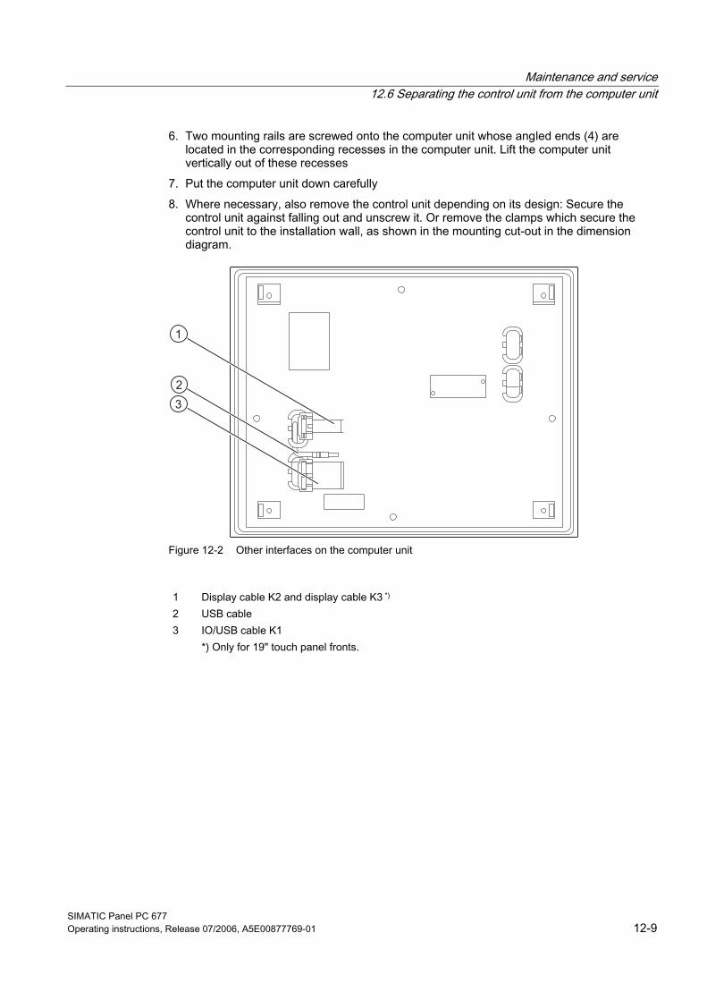
Maintenance and service 12.6 Separating the control unit from the computer unit
SIMATIC Panel PC 677 Operating instructions, Release 07/2006, A5E00877769-01 12-9
6. Two mounting rails are screwed onto the computer unit whose angled ends (4) are located in the corresponding recesses in the computer unit. Lift the computer unit vertically out of these recesses
7. Put the computer unit down carefully 8. Where necessary, also remove the control unit depending on its design: Secure the
control unit against falling out and unscrew it. Or remove the clamps which secure the control unit to the installation wall, as shown in the mounting cut-out in the dimension diagram.
Figure 12-2 Other interfaces on the computer unit
1 Display cable K2 and display cable K3 *) 2 USB cable 3 IO/USB cable K1 *) Only for 19" touch panel fronts.
Maintenance and service 12.6 Separating the control unit from the computer unit
SIMATIC Panel PC 677 12-10 Operating instructions, Release 07/2006, A5E00877769-01
Separating the device in an uninstalled state As an alternative, dismount the device completely and separate the control unit and computer unit from one another in an uninstalled state. So that the processing unit, which is swung away from the control unit, does not bend the lugs (4), place a surface under the processing unit.
Mounting operator control unit on computer unit To mount the operator control unit on the computer unit, perform the steps in reverse:
Caution When you swing the control unit and processing unit together, make sure that the flatband cables are correctly folded together and do not get squished.
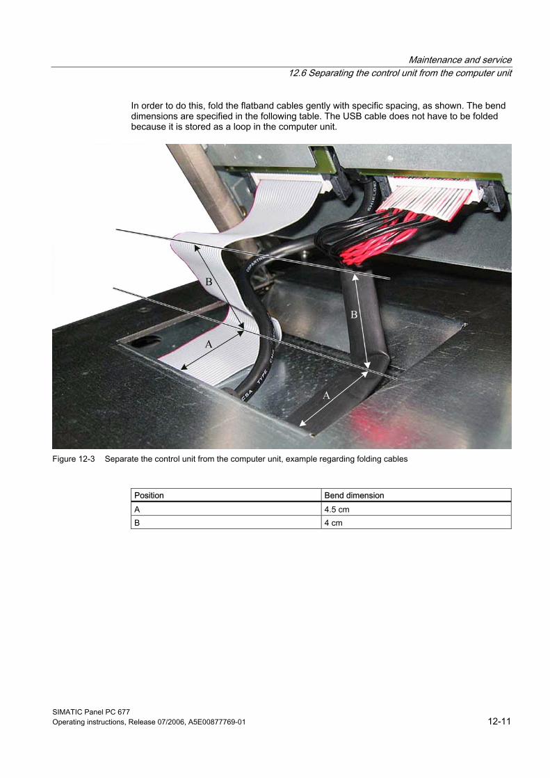
Maintenance and service 12.6 Separating the control unit from the computer unit
SIMATIC Panel PC 677 Operating instructions, Release 07/2006, A5E00877769-01 12-11
In order to do this, fold the flatband cables gently with specific spacing, as shown. The bend dimensions are specified in the following table. The USB cable does not have to be folded because it is stored as a loop in the computer unit.
Figure 12-3 Separate the control unit from the computer unit, example regarding folding cables
Position Bend dimension A 4.5 cm B 4 cm
Maintenance and service 12.7 Removing and installing hardware components
SIMATIC Panel PC 677 12-12 Operating instructions, Release 07/2006, A5E00877769-01
12.7 12.7 Removing and installing hardware components
12.7.1 Repairs
Notice Similar to figure The images presented below deviate slightly from the actual device in some respects.
Carrying out repairs Only authorized personnel are permitted to repair the device.
Warning Unauthorized opening and improper repairs on the device may result in substantial damage to equipment or endanger the user.
• Before you open the device, always disconnect the power plug. • Install only system upgrades designated for this computer and released by SIEMENS. All
technical data and licenses apply only to upgrades approved by SIEMENS. Installation of unsuitable components violates the regulations for UL approval and EMC. Impermissible expansions can damage the system. Contact your technical support team or your sales outlet to find out which system upgrades are suitable for installation.
If you install or exchange system expansions that damage your device, or if you use unsuitable components, the warranty becomes void.
Notice Note the ESD instructions.
Limitation of Liability No liability can be accepted for impairment of functions caused by the use of third-party devices or components.
Tools You can perform all installation tasks on the device using Torx T6, Torx T10, and Torx T20 screwdrivers and a Philips screwdriver.
Maintenance and service 12.7 Removing and installing hardware components
SIMATIC Panel PC 677 Operating instructions, Release 07/2006, A5E00877769-01 12-13
12.7.2 Open the device
Caution Work on the open device may only be carried out by authorized and qualified personnel. Within the warranty time, you are only allowed to install expansions for memory and expansion card modules.
Caution The device contains electronic components which may be destroyed by electrostatic charge.You therefore need to take precautionary measures before you open the device. Refer to the (ESD) directives for handling components which are sensitive to electrostatic charge.
Tools All mechanical installation tasks on the device can be carried out with Torx T6, T10 and T25 screwdrivers.
Preparation Disconnect the device from mains.
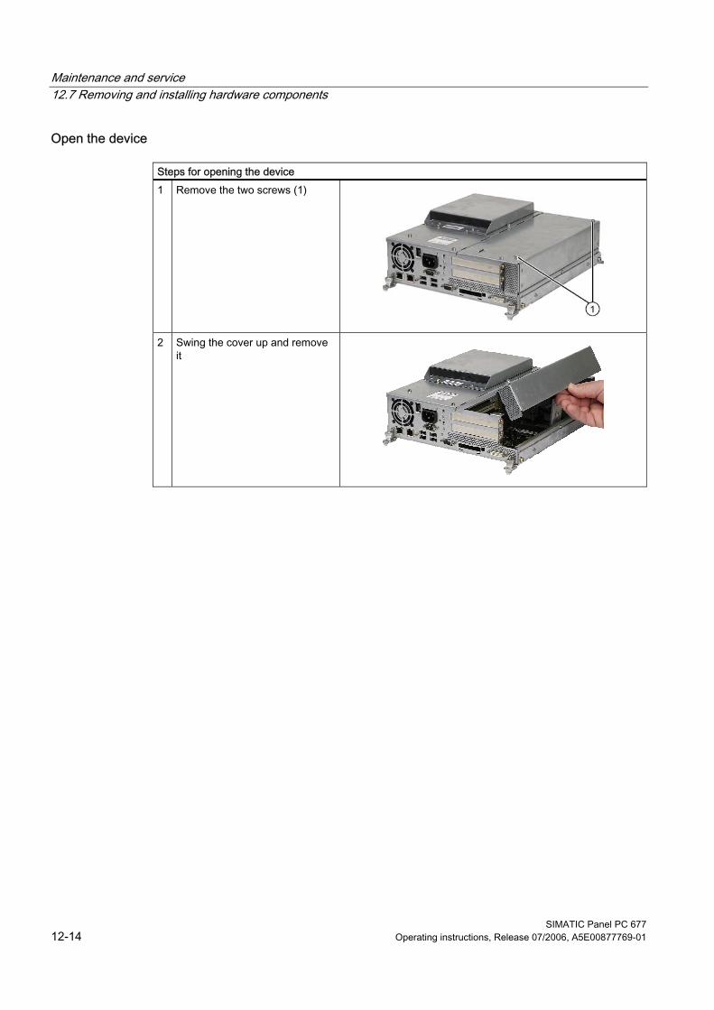
Maintenance and service 12.7 Removing and installing hardware components
SIMATIC Panel PC 677 12-14 Operating instructions, Release 07/2006, A5E00877769-01
Open the device
Steps for opening the device 1 Remove the two screws (1)
2 Swing the cover up and remove it

Maintenance and service 12.7 Removing and installing hardware components
SIMATIC Panel PC 677 Operating instructions, Release 07/2006, A5E00877769-01 12-15
12.7.3 Removing/Installing Memory Module
Memory expansion options The motherboard is equipped with 2 slots for memory modules. For 184-pin DDR2 RAM chips, unbuffered, no ECC. This allows you to expand the memory capacity of your PC to a maximum of 2 GB. One or two modules can be installed.
Combination Slot X1 Slot X2 Maximum
expansion 1 256 MB/512 MB/1 GB 1 GB 2 256 MB/512 MB/1 GB 256 MB/512 MB/1 GB 2 GB
Note Any module can be plugged into any slot.
Preparation Disconnect the device from mains and unplug all cables.
Caution The electronic components on the PCBS are highly sensitive to electrostatic discharge. It is therefore vital to take precautionary measures when handling these components. Refer to the directives for handling electrostatic sensitive components.
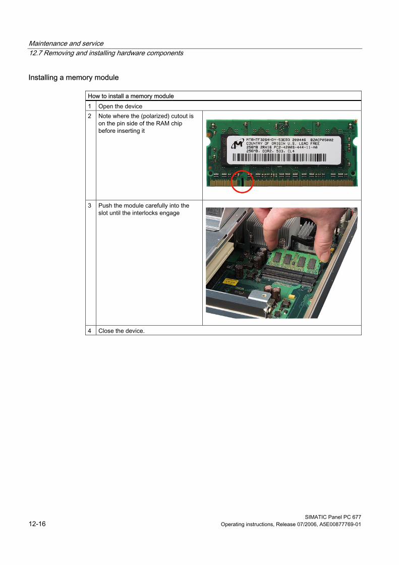
Maintenance and service 12.7 Removing and installing hardware components
SIMATIC Panel PC 677 12-16 Operating instructions, Release 07/2006, A5E00877769-01
Installing a memory module
How to install a memory module 1 Open the device 2 Note where the (polarized) cutout is
on the pin side of the RAM chip before inserting it
3 Push the module carefully into the
slot until the interlocks engage
4 Close the device.
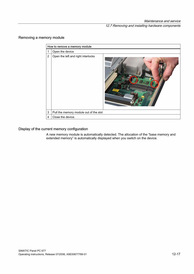
Maintenance and service 12.7 Removing and installing hardware components
SIMATIC Panel PC 677 Operating instructions, Release 07/2006, A5E00877769-01 12-17
Removing a memory module
How to remove a memory module 1 Open the device 2 Open the left and right interlocks
3 Pull the memory module out of the slot 4 Close the device.
Display of the current memory configuration A new memory module is automatically detected. The allocation of the ”base memory and extended memory” is automatically displayed when you switch on the device.
Maintenance and service 12.7 Removing and installing hardware components
SIMATIC Panel PC 677 12-18 Operating instructions, Release 07/2006, A5E00877769-01
12.7.4 PCI cards
12.7.4.1 Notes on the modules
The device is designed for use with modules conforming to PCI specifications V 2.2. PCI modules with 5 V and 3.3 V supply voltage can be operated. The permitted dimensions of the modules are found in the dimensional drawings section.
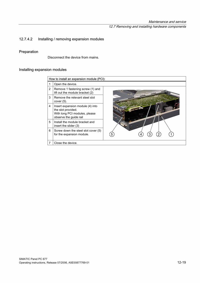
Maintenance and service 12.7 Removing and installing hardware components
SIMATIC Panel PC 677 Operating instructions, Release 07/2006, A5E00877769-01 12-19
12.7.4.2 Installing / removing expansion modules
Preparation Disconnect the device from mains.
Installing expansion modules
How to install an expansion module (PCI): 1 Open the device. 2 Remove 1 fastening screw (1) and
lift out the module bracket (2) 3 Remove the relevant steel slot
cover (5). 4 Insert expansion module (4) into
the slot provided. With long PCI modules, please observe the guide rail
5 Install the module bracket and insert the slider (3)
6 Screw down the steel slot cover (5) for the expansion module.
7 Close the device.
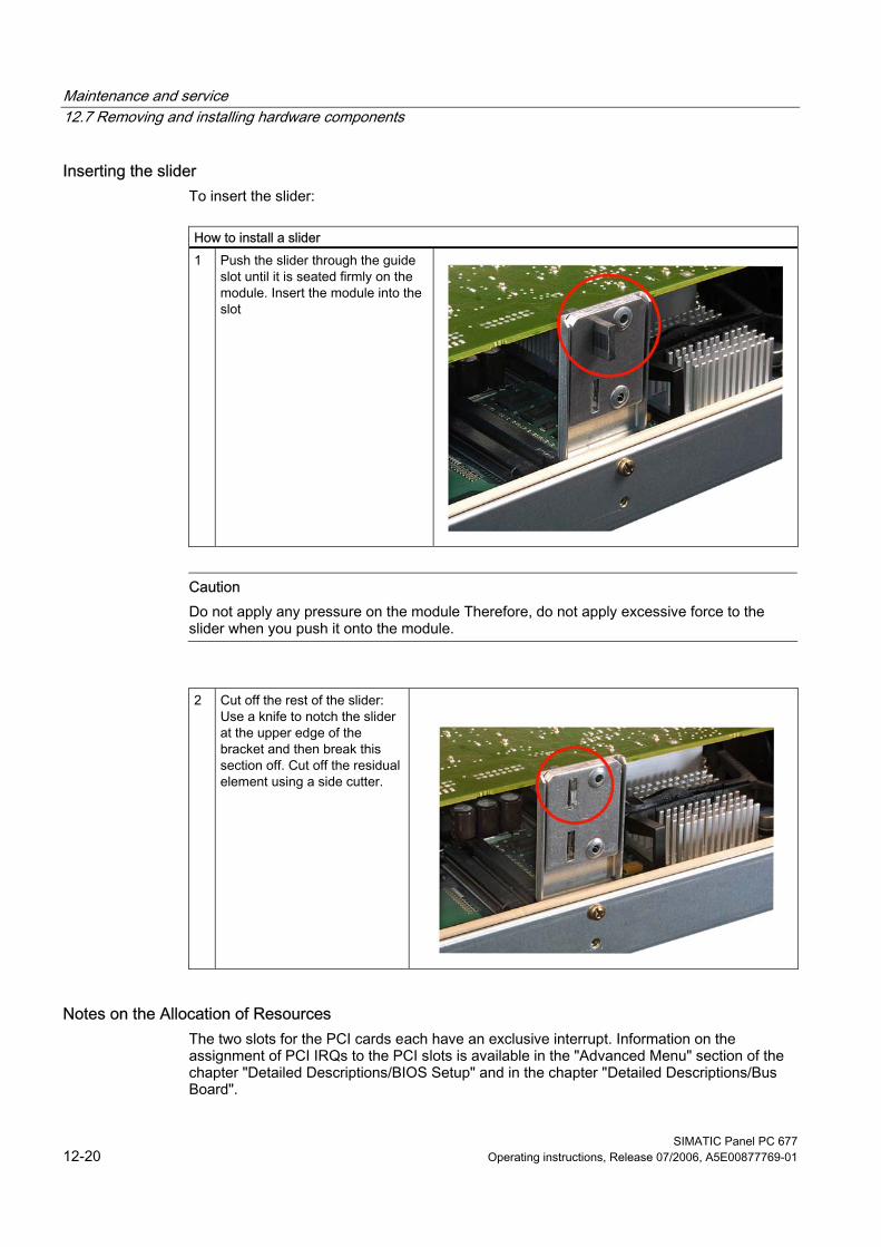
Maintenance and service 12.7 Removing and installing hardware components
SIMATIC Panel PC 677 12-20 Operating instructions, Release 07/2006, A5E00877769-01
Inserting the slider To insert the slider:
How to install a slider 1 Push the slider through the guide
slot until it is seated firmly on the module. Insert the module into the slot
Caution
Do not apply any pressure on the module Therefore, do not apply excessive force to the slider when you push it onto the module.
2 Cut off the rest of the slider: Use a knife to notch the slider at the upper edge of the bracket and then break this section off. Cut off the residual element using a side cutter.
Notes on the Allocation of Resources The two slots for the PCI cards each have an exclusive interrupt. Information on the assignment of PCI IRQs to the PCI slots is available in the "Advanced Menu" section of the chapter "Detailed Descriptions/BIOS Setup" and in the chapter "Detailed Descriptions/Bus Board".
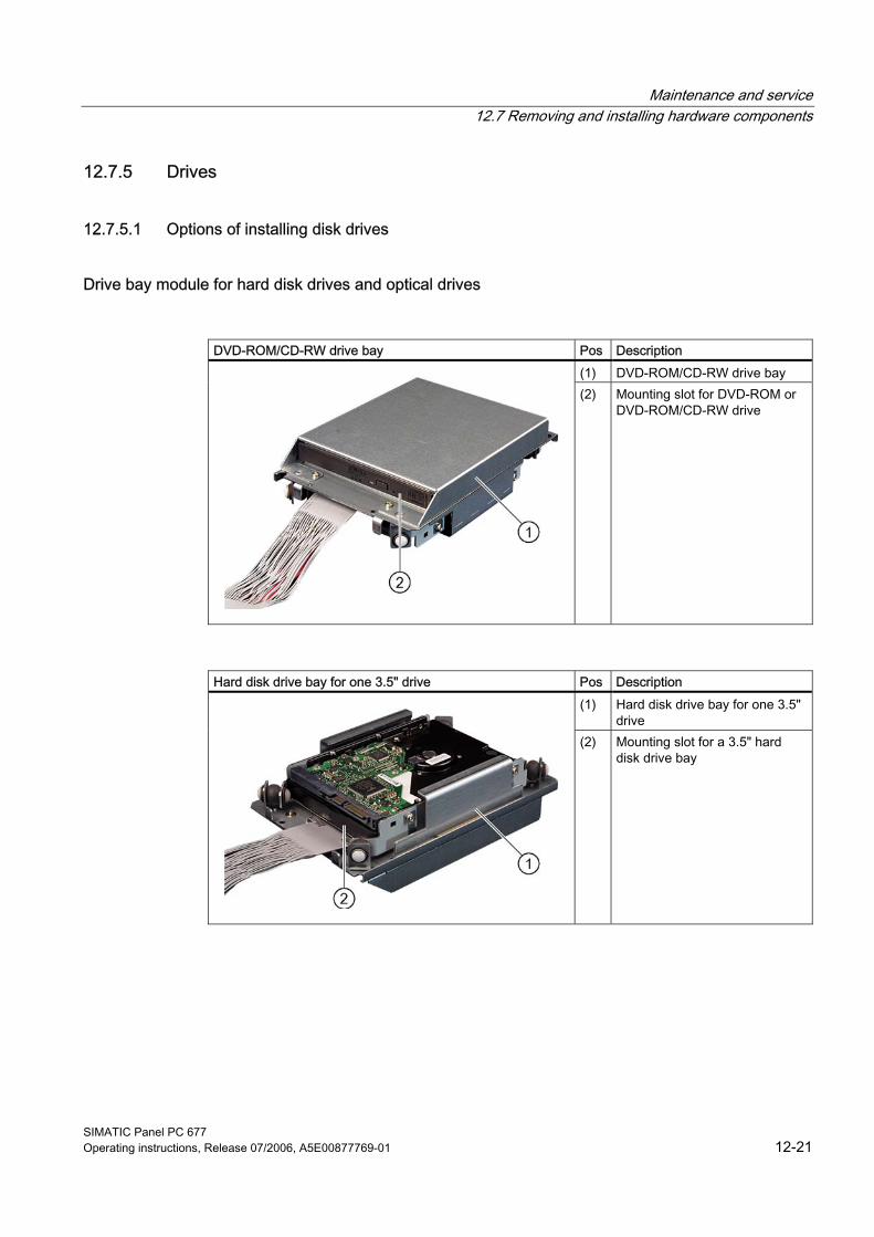
Maintenance and service 12.7 Removing and installing hardware components
SIMATIC Panel PC 677 Operating instructions, Release 07/2006, A5E00877769-01 12-21
12.7.5 Drives
12.7.5.1 Options of installing disk drives
Drive bay module for hard disk drives and optical drives
DVD-ROM/CD-RW drive bay Pos Description
(1) DVD-ROM/CD-RW drive bay
(2) Mounting slot for DVD-ROM or DVD-ROM/CD-RW drive
Hard disk drive bay for one 3.5" drive Pos Description (1) Hard disk drive bay for one 3.5"
drive
(2) Mounting slot for a 3.5" hard disk drive bay
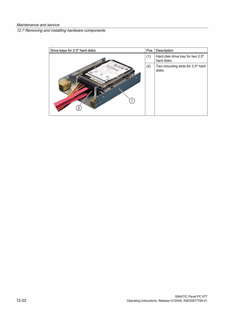
Maintenance and service 12.7 Removing and installing hardware components
SIMATIC Panel PC 677 12-22 Operating instructions, Release 07/2006, A5E00877769-01
Drive bays for 2.5" hard disks Pos Description
(1) Hard disk drive bay for two 2.5" hard disks
(2) Two mounting slots for 2.5" hard disks
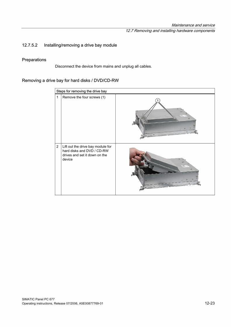
Maintenance and service 12.7 Removing and installing hardware components
SIMATIC Panel PC 677 Operating instructions, Release 07/2006, A5E00877769-01 12-23
12.7.5.2 Installing/removing a drive bay module
Preparations Disconnect the device from mains and unplug all cables.
Removing a drive bay for hard disks / DVD/CD-RW
Steps for removing the drive bay 1 Remove the four screws (1)
2 Lift out the drive bay module for hard disks and DVD / CD-RW drives and set it down on the device
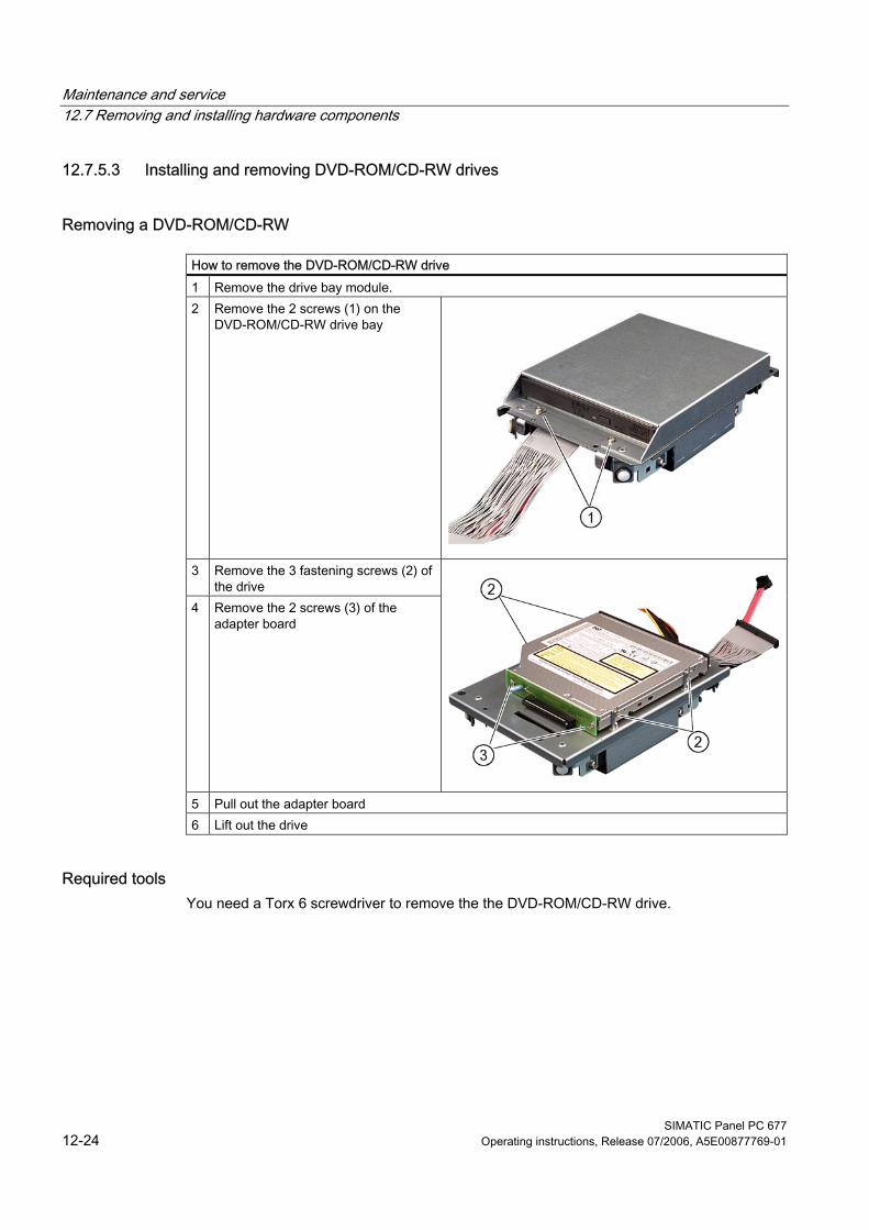
Maintenance and service 12.7 Removing and installing hardware components
SIMATIC Panel PC 677 12-24 Operating instructions, Release 07/2006, A5E00877769-01
12.7.5.3 Installing and removing DVD-ROM/CD-RW drives
Removing a DVD-ROM/CD-RW
How to remove the DVD-ROM/CD-RW drive 1 Remove the drive bay module. 2 Remove the 2 screws (1) on the
DVD-ROM/CD-RW drive bay
3 Remove the 3 fastening screws (2) of
the drive 4 Remove the 2 screws (3) of the
adapter board
5 Pull out the adapter board 6 Lift out the drive
Required tools You need a Torx 6 screwdriver to remove the the DVD-ROM/CD-RW drive.
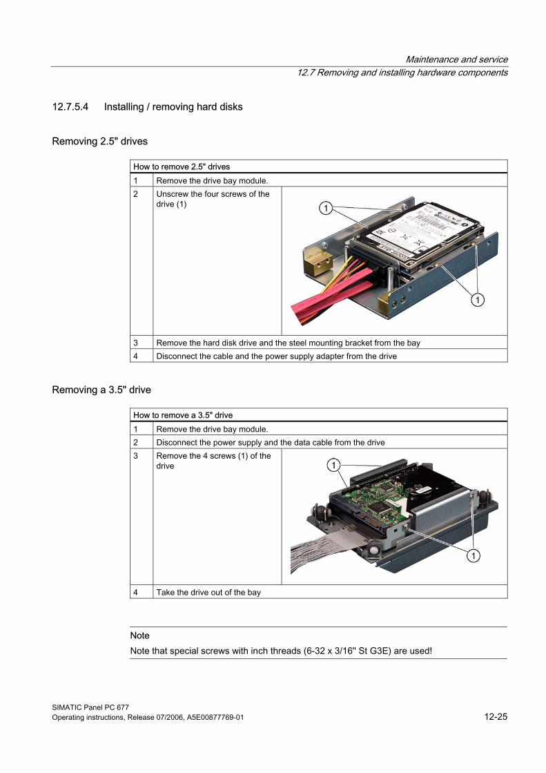
Maintenance and service 12.7 Removing and installing hardware components
SIMATIC Panel PC 677 Operating instructions, Release 07/2006, A5E00877769-01 12-25
12.7.5.4 Installing / removing hard disks
Removing 2.5" drives
How to remove 2.5" drives 1 Remove the drive bay module. 2 Unscrew the four screws of the
drive (1)
3 Remove the hard disk drive and the steel mounting bracket from the bay 4 Disconnect the cable and the power supply adapter from the drive
Removing a 3.5" drive
How to remove a 3.5" drive 1 Remove the drive bay module. 2 Disconnect the power supply and the data cable from the drive 3 Remove the 4 screws (1) of the
drive
4 Take the drive out of the bay
Note Note that special screws with inch threads (6-32 x 3/16'' St G3E) are used!
Maintenance and service 12.7 Removing and installing hardware components
SIMATIC Panel PC 677 12-26 Operating instructions, Release 07/2006, A5E00877769-01
12.7.6 Installing/removing a Compact Flash card
Memory expansion options The device features a card reader slot for Compact Flash cards (types I / II). We recommend Compact Flash cards for industrial application (industrial grade cards from the company SANDISK, for example). These have distinguished themselves with especially good data security, a long life and excellent data transmissions rates.
Notice This slot is not hot-plug capable. The Compact Flash card must be installed before the PC is switched on and should only be removed when the device is switched off.
Preparation Disconnect the PC from mains.
Caution The electronic components on the PCBS are highly sensitive to electrostatic discharge. It is therefore vital to take precautionary measures when handling these components. Refer to the directives for handling electrostatic sensitive components.
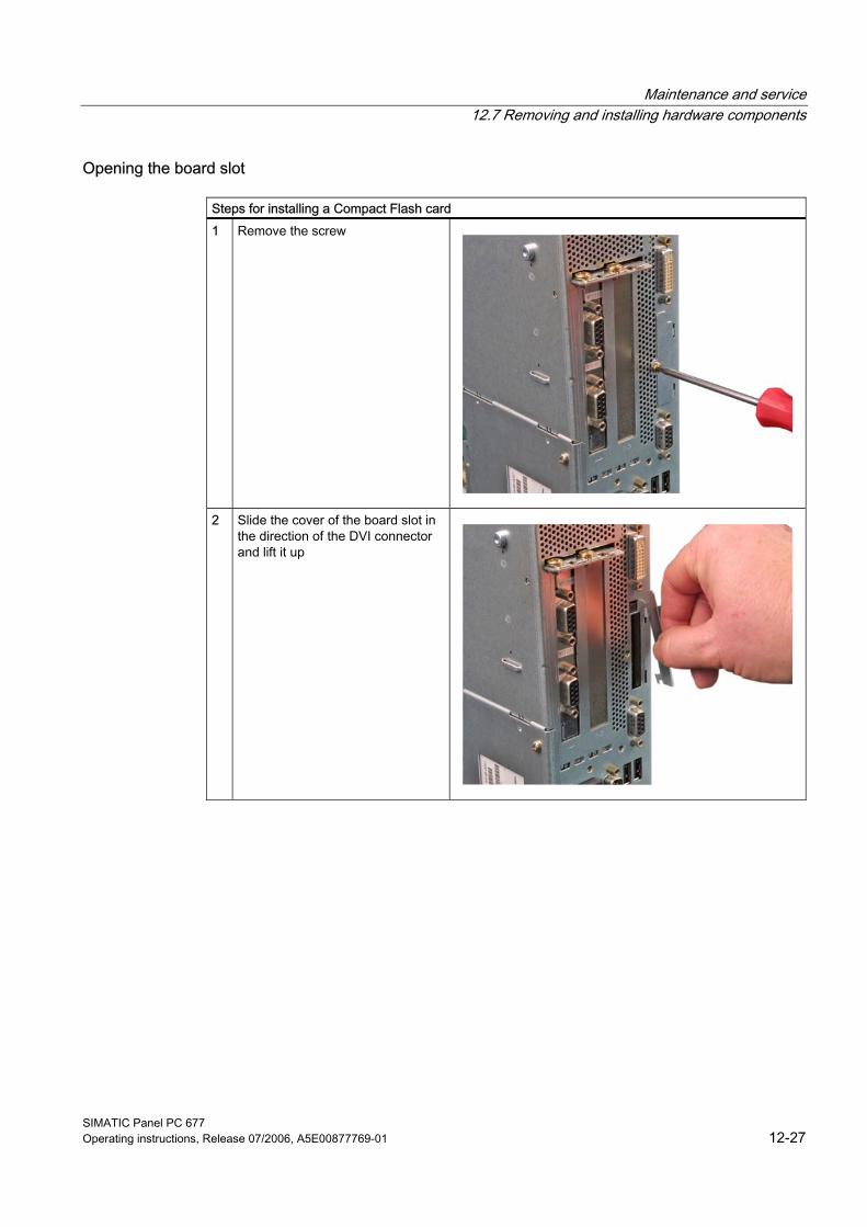
Maintenance and service 12.7 Removing and installing hardware components
SIMATIC Panel PC 677 Operating instructions, Release 07/2006, A5E00877769-01 12-27
Opening the board slot
Steps for installing a Compact Flash card 1 Remove the screw
2 Slide the cover of the board slot in
the direction of the DVI connector and lift it up
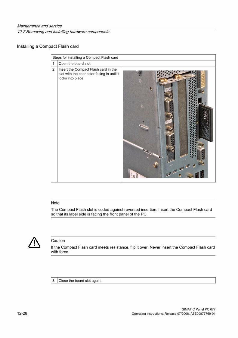
Maintenance and service 12.7 Removing and installing hardware components
SIMATIC Panel PC 677 12-28 Operating instructions, Release 07/2006, A5E00877769-01
Installing a Compact Flash card
Steps for installing a Compact Flash card 1 Open the board slot. 2 Insert the Compact Flash card in the
slot with the connector facing in until it locks into place
Note The Compact Flash slot is coded against reversed insertion. Insert the Compact Flash card so that its label side is facing the front panel of the PC.
Caution If the Compact Flash card meets resistance, flip it over. Never insert the Compact Flash card with force.
3 Close the board slot again.
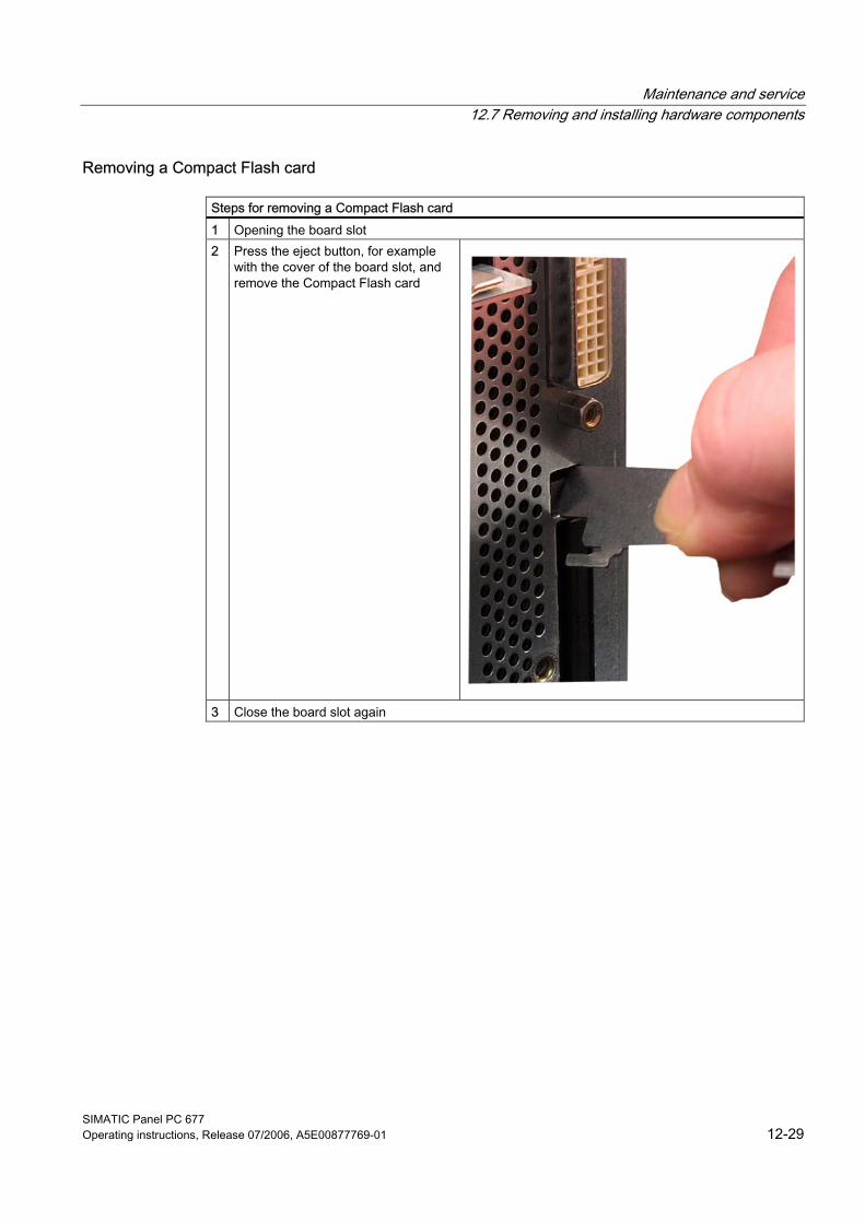
Maintenance and service 12.7 Removing and installing hardware components
SIMATIC Panel PC 677 Operating instructions, Release 07/2006, A5E00877769-01 12-29
Removing a Compact Flash card
Steps for removing a Compact Flash card 1 Opening the board slot 2 Press the eject button, for example
with the cover of the board slot, and remove the Compact Flash card
3 Close the board slot again
Maintenance and service 12.7 Removing and installing hardware components
SIMATIC Panel PC 677 12-30 Operating instructions, Release 07/2006, A5E00877769-01
12.7.7 Replacing the backup battery
Note Batteries are wearing parts and should be replaced every five years in order to ensure proper functioning of the PC.
To be noted before you replace the battery
Caution Risk of damage! The lithium battery may only be replaced with an identical battery or with a type recommended by the manufacturer (Order No.: A5E00331143).
Warning Risk of explosion and release of harmful substances! Therefore, do not throw Lithium batteries into an open fire, do not solder or open the cell body, do not short-circuit or reverse polarity, do not heat up above 100° C, dispose as regulated and protected against direct exposure to sunlight, humidity and dewing.
Disposal
Caution Batteries must be disposed of in accordance with local regulations.
Maintenance and service 12.7 Removing and installing hardware components
SIMATIC Panel PC 677 Operating instructions, Release 07/2006, A5E00877769-01 12-31
Preparation
Note For the BIOS setting "Profile: Standard" the configuration data of the device is deleted when the battery is replaced. For the BIOS setting "Profile: User" the configuration data of the device is retained; only the date and time has to be reconfigured.
9. Note down the current settings of the BIOS setup. A list in which you can note down your entries is found in the BIOS manual.
10. Disconnect the device from mains and unplug all cables.
Notice The battery can also be exchanged when the device is operating. However, we recommend switching off the device, beforehand.
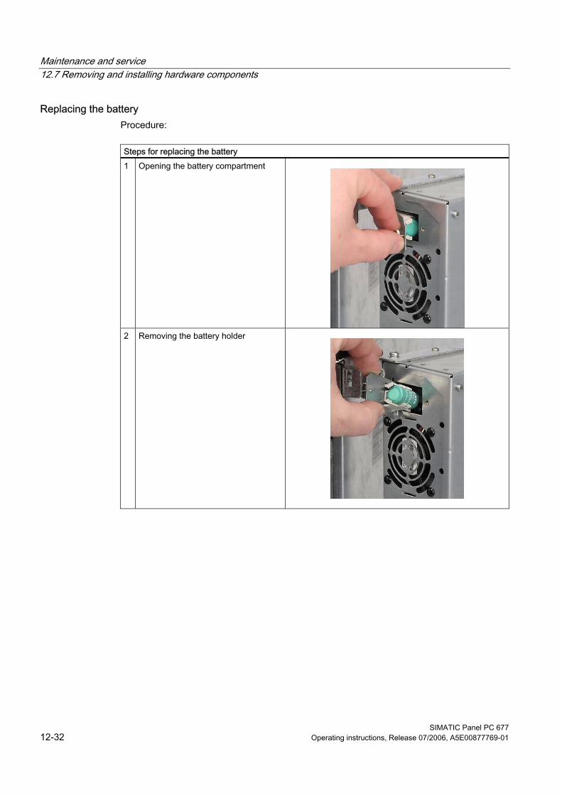
Maintenance and service 12.7 Removing and installing hardware components
SIMATIC Panel PC 677 12-32 Operating instructions, Release 07/2006, A5E00877769-01
Replacing the battery Procedure:
Steps for replacing the battery 1 Opening the battery compartment
2 Removing the battery holder
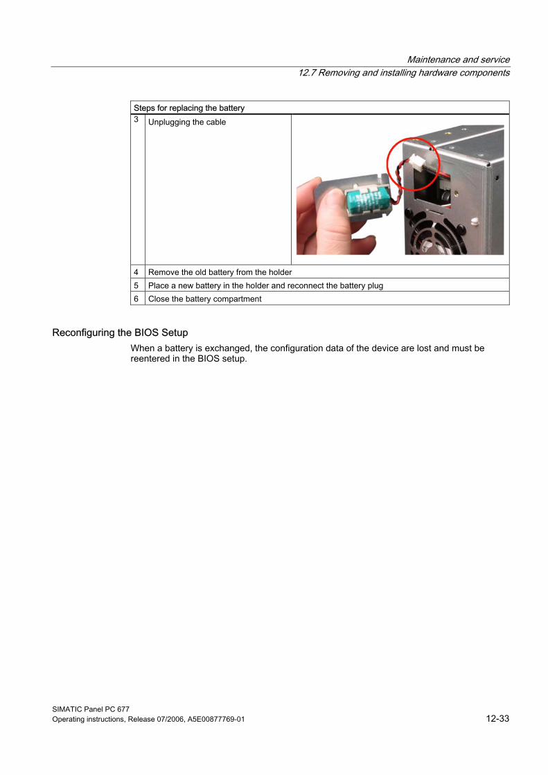
Maintenance and service 12.7 Removing and installing hardware components
SIMATIC Panel PC 677 Operating instructions, Release 07/2006, A5E00877769-01 12-33
Steps for replacing the battery 3 Unplugging the cable
4 Remove the old battery from the holder 5 Place a new battery in the holder and reconnect the battery plug 6 Close the battery compartment
Reconfiguring the BIOS Setup When a battery is exchanged, the configuration data of the device are lost and must be reentered in the BIOS setup.
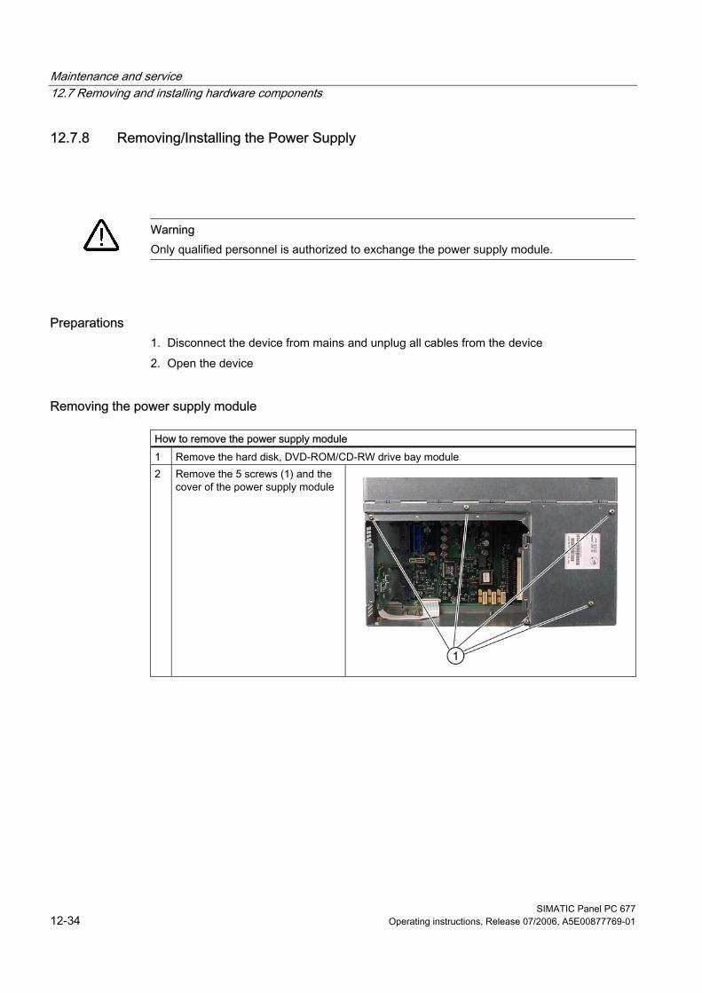
Maintenance and service 12.7 Removing and installing hardware components
SIMATIC Panel PC 677 12-34 Operating instructions, Release 07/2006, A5E00877769-01
12.7.8 Removing/Installing the Power Supply
Warning Only qualified personnel is authorized to exchange the power supply module.
Preparations 1. Disconnect the device from mains and unplug all cables from the device 2. Open the device
Removing the power supply module
How to remove the power supply module 1 Remove the hard disk, DVD-ROM/CD-RW drive bay module 2 Remove the 5 screws (1) and the
cover of the power supply module
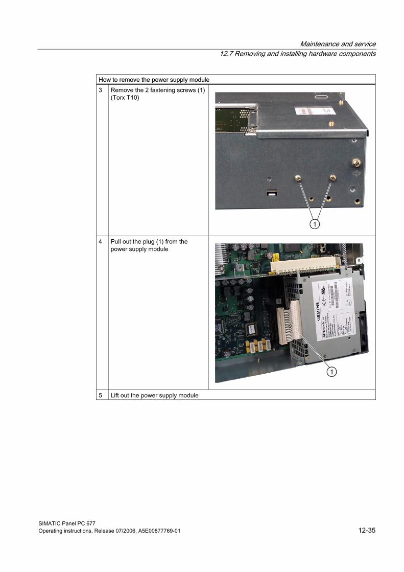
Maintenance and service 12.7 Removing and installing hardware components
SIMATIC Panel PC 677 Operating instructions, Release 07/2006, A5E00877769-01 12-35
How to remove the power supply module 3 Remove the 2 fastening screws (1)
(Torx T10)
4 Pull out the plug (1) from the power supply module
5 Lift out the power supply module

Maintenance and service 12.7 Removing and installing hardware components
SIMATIC Panel PC 677 12-36 Operating instructions, Release 07/2006, A5E00877769-01
12.7.9 Installing / removing the bus board
Preparation 1. Disconnect the device from mains and unplug all cables. 2. Open the device.
Removing the bus board
How to remove the bus board 1 Remove all modules from their slots 2 Remove the drive bay module for hard disks and DVD-ROM/CD-RW 3 Remove the power supply cover:
Remove the seven screws (1)
4 Remove the power supply module. 5 Remove the 3 screws (1) on the bus
board
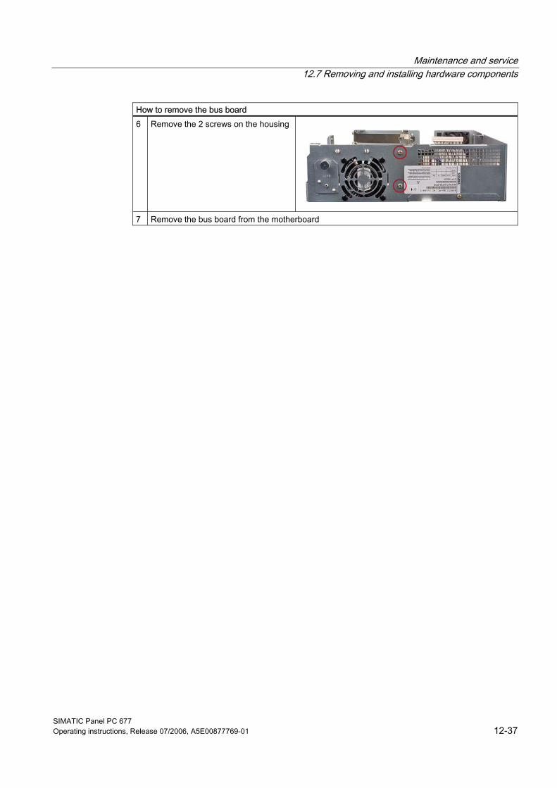
Maintenance and service 12.7 Removing and installing hardware components
SIMATIC Panel PC 677 Operating instructions, Release 07/2006, A5E00877769-01 12-37
How to remove the bus board 6 Remove the 2 screws on the housing
7 Remove the bus board from the motherboard
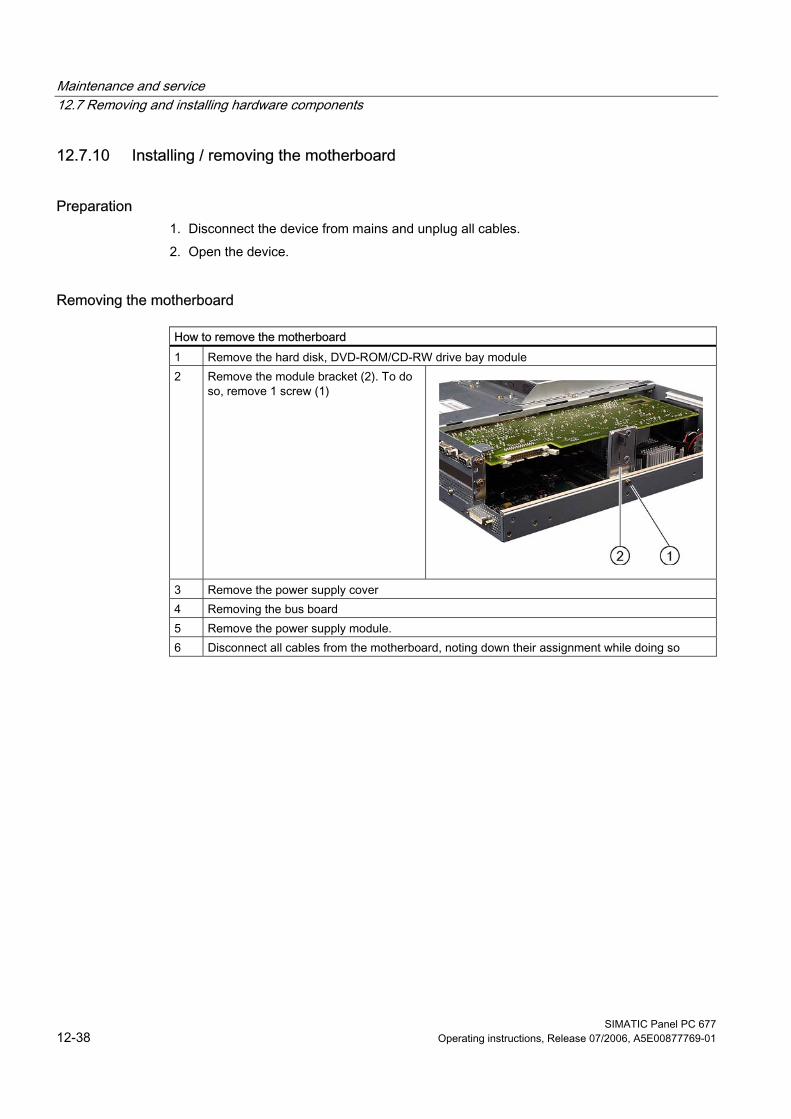
Maintenance and service 12.7 Removing and installing hardware components
SIMATIC Panel PC 677 12-38 Operating instructions, Release 07/2006, A5E00877769-01
12.7.10 Installing / removing the motherboard
Preparation 1. Disconnect the device from mains and unplug all cables. 2. Open the device.
Removing the motherboard
How to remove the motherboard 1 Remove the hard disk, DVD-ROM/CD-RW drive bay module 2 Remove the module bracket (2). To do
so, remove 1 screw (1)
3 Remove the power supply cover 4 Removing the bus board 5 Remove the power supply module. 6 Disconnect all cables from the motherboard, noting down their assignment while doing so
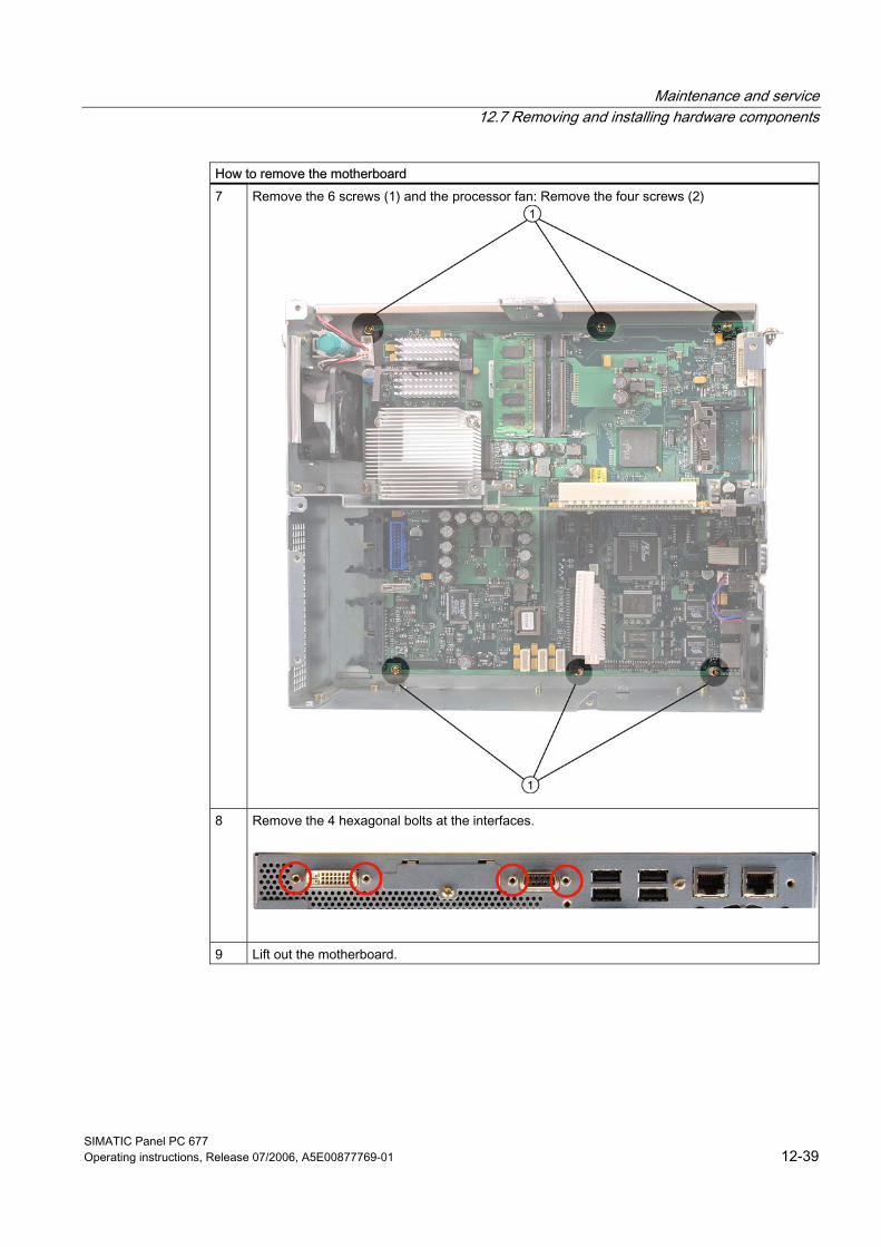
Maintenance and service 12.7 Removing and installing hardware components
SIMATIC Panel PC 677 Operating instructions, Release 07/2006, A5E00877769-01 12-39
How to remove the motherboard 7 Remove the 6 screws (1) and the processor fan: Remove the four screws (2)
8 Remove the 4 hexagonal bolts at the interfaces.
9 Lift out the motherboard.
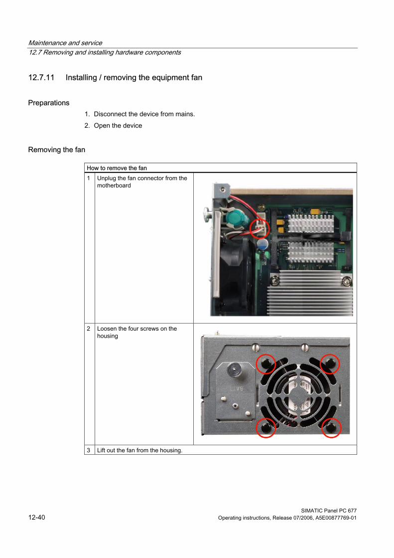
Maintenance and service 12.7 Removing and installing hardware components
SIMATIC Panel PC 677 12-40 Operating instructions, Release 07/2006, A5E00877769-01
12.7.11 Installing / removing the equipment fan
Preparations 1. Disconnect the device from mains. 2. Open the device
Removing the fan
How to remove the fan 1 Unplug the fan connector from the
motherboard
2 Loosen the four screws on the
housing
3 Lift out the fan from the housing.
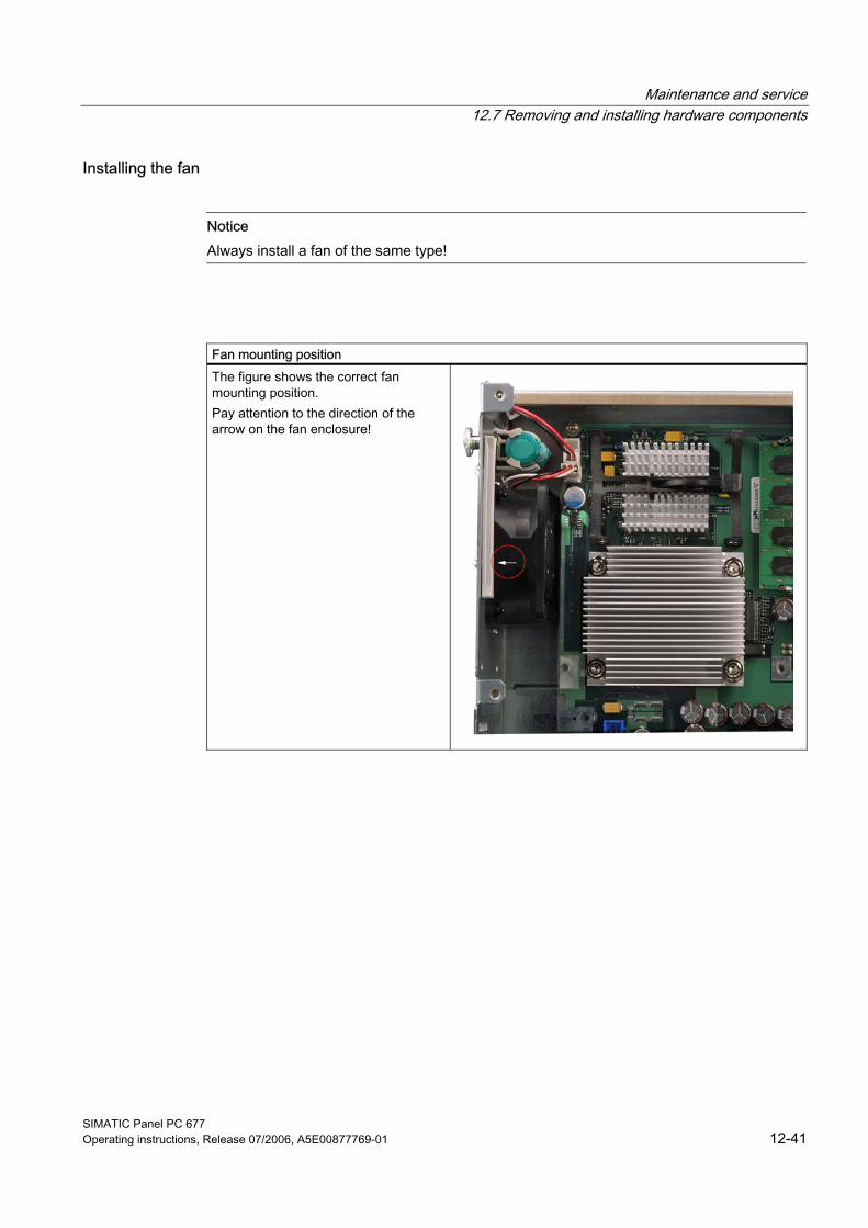
Maintenance and service 12.7 Removing and installing hardware components
SIMATIC Panel PC 677 Operating instructions, Release 07/2006, A5E00877769-01 12-41
Installing the fan
Notice Always install a fan of the same type!
Fan mounting position The figure shows the correct fan mounting position. Pay attention to the direction of the arrow on the fan enclosure!
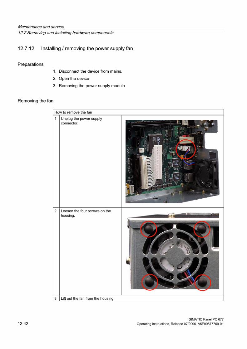
Maintenance and service 12.7 Removing and installing hardware components
SIMATIC Panel PC 677 12-42 Operating instructions, Release 07/2006, A5E00877769-01
12.7.12 Installing / removing the power supply fan
Preparations 1. Disconnect the device from mains. 2. Open the device 3. Removing the power supply module
Removing the fan
How to remove the fan 1 Unplug the power supply
connector.
2 Loosen the four screws on the housing.
3 Lift out the fan from the housing.
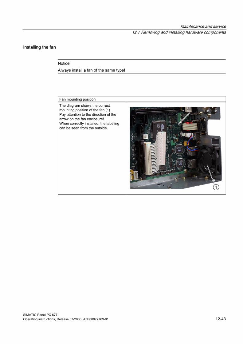
Maintenance and service 12.7 Removing and installing hardware components
SIMATIC Panel PC 677 Operating instructions, Release 07/2006, A5E00877769-01 12-43
Installing the fan
Notice Always install a fan of the same type!
Fan mounting position The diagram shows the correct mounting position of the fan (1). Pay attention to the direction of the arrow on the fan enclosure! When correctly installed, the labeling can be seen from the outside.
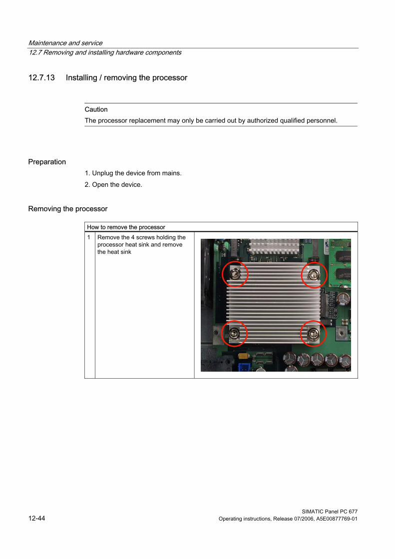
Maintenance and service 12.7 Removing and installing hardware components
SIMATIC Panel PC 677 12-44 Operating instructions, Release 07/2006, A5E00877769-01
12.7.13 Installing / removing the processor
Caution The processor replacement may only be carried out by authorized qualified personnel.
Preparation 1. Unplug the device from mains. 2. Open the device.
Removing the processor
How to remove the processor 1 Remove the 4 screws holding the
processor heat sink and remove the heat sink
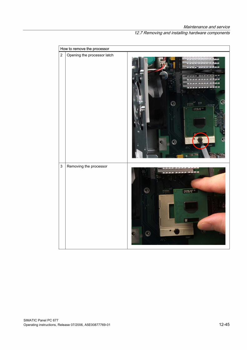
Maintenance and service 12.7 Removing and installing hardware components
SIMATIC Panel PC 677 Operating instructions, Release 07/2006, A5E00877769-01 12-45
How to remove the processor 2 Opening the processor latch
3 Removing the processor
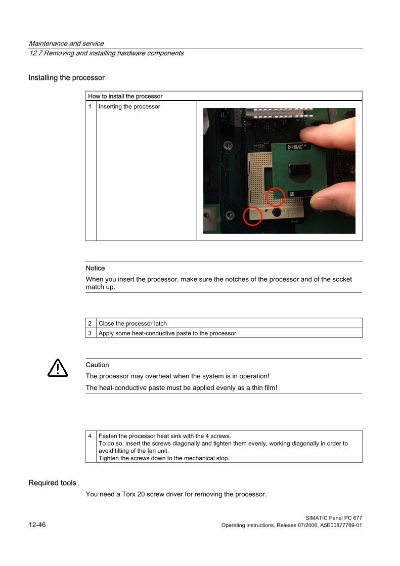
Maintenance and service 12.7 Removing and installing hardware components
SIMATIC Panel PC 677 12-46 Operating instructions, Release 07/2006, A5E00877769-01
Installing the processor
How to install the processor 1 Inserting the processor
Notice When you insert the processor, make sure the notches of the processor and of the socket match up.
2 Close the processor latch 3 Apply some heat-conductive paste to the processor
Caution The processor may overheat when the system is in operation! The heat-conductive paste must be applied evenly as a thin film!
4 Fasten the processor heat sink with the 4 screws. To do so, insert the screws diagonally and tighten them evenly, working diagonally in order to avoid tilting of the fan unit. Tighten the screws down to the mechanical stop.
Required tools You need a Torx 20 screw driver for removing the processor.
Maintenance and service 12.8 Installing the software
SIMATIC Panel PC 677 Operating instructions, Release 07/2006, A5E00877769-01 12-47
12.8 12.8 Installing the software
12.8.1 General installation procedure
If the system is unstable or if the operating system reports errors, the delivery status of the device can be easily restored using the Restore DVD. You can re-install the operating system and relevant drivers using the Recovery CD and the "Documentation and Drivers" CD.
Recovery CD: The new recovery procedure is based on Windows PE (Preinstalled Environment). The CD contains a Windows PE user interface with tools for configuring the hard drives and the operating system.
Documentation and Drivers CD: Contains the documentation and the hardware drivers.
Restore DVD: Contains a hard disk image file with the original software (operating system with installed hardware drivers).
Maintenance and service 12.8 Installing the software
SIMATIC Panel PC 677 12-48 Operating instructions, Release 07/2006, A5E00877769-01
12.8.2 Setting up the partitions for Windows operating systems After you have installed a new hard disk, or if partitions are faulty, or when you wish to change the partitioning on your hard disk, you need to create or reconfigure partitions on the hard disk
Caution When you delete or create partitions or logical DOS partitions, you lose all data on the hard disk. All partitions on the hard disk will be deleted.
With the Windows 2000 Professional and Windows XP Professional operating systems, the factory state features two partitions with an NTFS file system on the hard disk. To restore the partitions to factory state, proceed as follows:
Setting up partitions 1. Boot from the Recovery CD and then follow the screen instructions until the Recovery
functions window is displayed. 2. Start the DiskPart program in the "Siemens SIMATIC Recovery“ window and enter the
following commands in the displayed command interface:
list disk Displays all available hard disks. select disk 0 Selects the disk where you wish to change the configuration. 0
selects the first hard disk. list partition Displays all partitions on the selected hard disk 1) clean Completely wipes the selected hard disk. All information stored there
is lost. create partition primary size=n Creates a primary partition with the n MB on the selected hard disk.
Factory state values: n = 10000 for Windows 2000 Professional or XP Professional
select partition 1 Select the primary partition active Activates the selected partition 1) exit Closes DiskPart. 1) The active partition is identified with a *.
Additional DiskPart functions:
Help Shows all available DiskPart commands. When a command is
supplemented with other parameters, the command is described with additional information. Example: create partition help
Maintenance and service 12.8 Installing the software
SIMATIC Panel PC 677 Operating instructions, Release 07/2006, A5E00877769-01 12-49
Note Once you have changed the configuration of your hard disk with DiskPart, you will need to reboot the PC for the changes to go into effect. Boot again from the Recovery CD to format the partitions.
Format primary partition 1. Boot from the Recovery CD to format the partitions. Follow the screen instructions until
the Recovery functions window is displayed. 2. Select "Start command prompt" in the Recovery functions window. In the command
interface that opens, enter the following command: format DL:/FS:File System DL = Drive letter of the partition to be formatted. Valid values: C, D, E, F etc. File system = Specifies the type of file system. Valid values: FAT, FAT32, NTFS.
NTFS is the factory setting for all Windows operating systems. Example for a master hard disk on the IDE bus: format C:/FS:NTFS
Note Parameter overview format /? shows all parameters of the command.
Maintenance and service 12.8 Installing the software
SIMATIC Panel PC 677 12-50 Operating instructions, Release 07/2006, A5E00877769-01
12.8.3 Compatibility of the Restore DVD
Caution Use only the supplied Restore DVDs for the device. Verify that the order number of the Restore DVD matches that of the device. You can find the order number of the device on the rating plate. Do not use the supplied images for any other device. The chipsets and drivers differ.
Maintenance and service 12.8 Installing the software
SIMATIC Panel PC 677 Operating instructions, Release 07/2006, A5E00877769-01 12-51
12.8.4 Restoring the factory state of the software using the Restore DVD You can restore the software to the original factory state using the Restore CD (not included in all package variants). The DVD contains the necessary images and tools for transferring the factory software to the hard disk of your PC. You can restore the entire hard disk with drive C: (system) and drive D: or only drive C:. at the command line input. This allows you to retain any user data on drive D.
Recovering authorizations or license keys for SIMATIC software from the hard disk • If you have installed SIMATIC software with a license key or authorization on the PC,
please check if you can recover the license key or authorization on the hard disk. The transfer of license keys or authorizations is described in the Help of the Automation License Manager program.
• If it is not possible to backup your authorization, please contact the Customer Support Hotline. There you can obtain information necessary for your software authorization.
Caution With the option "Restore system partition only", all data on drive C: (System) will be deleted. All data, user settings and all authorizations or license keys on drive C: will be lost in the process! All data on drive C: of your hard disk will be deleted. Setup formats the hard disk partition and reinstalls the original factory software. When you select the "Restore entire hard disk" option, ALL the data, user settings and authorizations or license keys will be lost on the hard disk.
Restoring the factory state with the installed drive To restore the factory state, proceed as follows: 1. Make the following setting in the BIOS Setup:
Menu Exit > Get Default Values 2. Insert the Restore DVD in the drive and reboot the device. When the BIOS message
”Press <F2> to enter Setup or <ESC> to show Boot Menu" appears, press the ESC key. After initialization, a "Boot Menu" is displayed.
3. Select the optical drive with the cursor keys. 4. Now follow the instructions on the screen.
Caution All existing data, programs, user settings and authorizations or License Keyswill bedeleted from the hard disk and are therefore lost.
Maintenance and service 12.8 Installing the software
SIMATIC Panel PC 677 12-52 Operating instructions, Release 07/2006, A5E00877769-01
Restoring the factory state with an external USB CD/DVD ROM Procedure: 1. Connect the external USB CD/DVD ROM to the Panel PC and reboot the device. 2. Enter the external CD/DVD ROm in the "Boot priority order"
– Press <F2> when the BIOS message "Press <F2> to enter Setup" appears. – Select Advanced". – Add the external CD/DVD ROM by marking the external CD/DVD ROM with the cursor
keys. – Press the "include" key <x> to include the external CD/DVD ROM in the "Boot priority
order" list. – Save the settings and exit the BIOS with Save Changes & Exit – Switch off the Panel PC
3. Restoring the factory state – Place the Restore DVD into the external drive and restart the device using the on/off
switch (min. 15s). – During the self-test phase, press < ESC >. After initialization, a boot menu is
displayed. – Select the external optical drive with the cursor keys. – Now follow the instructions on the screen
Caution All existing data, programs, user settings and authorizations or License Keyswill bedeleted from the hard disk and are therefore lost.
For information on the functions, refer to the README.TXT file on the Restore DVD.
Maintenance and service 12.8 Installing the software
SIMATIC Panel PC 677 Operating instructions, Release 07/2006, A5E00877769-01 12-53
12.8.5 Installing Microsoft Windows operating systems
12.8.5.1 Operating system not installed The device can be optionally purchased without an operating system. If you want to install the operating system yourself, read the information available in the Internet at http://www.siemens.com/asis
Notice You must integrate the required software components yourself if you install an operating system not offered by Siemens AG. Note the following in this regard: — The device has features that a standard PC does not, for example, a touch screen and front panel function keys. — Siemens AG can only guarantee the availability of these features for operating systems that have been released. — Siemens AG only provides support within a strictly defined framework.
Maintenance and service 12.8 Installing the software
SIMATIC Panel PC 677 12-54 Operating instructions, Release 07/2006, A5E00877769-01
12.8.5.2 Booting from the Recovery CD Please use the Recovery CD to install Windows to meet your special requirements. The operating system used is Windows Preinstall Environment (WinPE). You will also need the supplied Documentation and Drivers CD. Booting with the Recovery CD: 1. Insert the Recovery CD in the drive and reboot the device. When the BIOS message
”Press <F2> to enter Setup or <ESC> to show Boot Menu" appears, press the ESC key. After initialization, a "Boot Menu" is displayed.
2. Select the optical drive with the cursor keys. 3. Please follow the on-screen instructions until the "Siemens SIMATIC Recovery" window
appears.
Maintenance and service 12.8 Installing the software
SIMATIC Panel PC 677 Operating instructions, Release 07/2006, A5E00877769-01 12-55
12.8.5.3 Installing the Microsoft Windows operating system (not for RAID) The recovery CD contains encrypted data that can only be transferred to this system.
Please use the Recovery CD to install Windows to meet your special requirements. The operating system used is Windows Preinstall Environment (WinPE). You will also need the supplied Documentation and Drivers CD. Booting with the Recovery CD 1. Boot from the Recovery CD and when the BIOS message
”Press <F2> to enter Setup or <ESC> to show Boot Menu" appears, press the ESC key. After initialization, a "Boot Menu" is displayed.
2. Select the optical drive with the cursor keys. 3. Please follow the on-screen instructions until the "Siemens SIMATIC Recovery" window
appears. 4. After copying the Windows installation files, return to the Siemens SIMATIC Recovery
main menu (click "Back"). 5. Select "Start command prompt" in the Recovery functions window. 6. Enter the following command in the displayed command prompt interface:
DL: cd \I386 Winnt32.bat DL: Drive letter of the folder containing the I386 directory.
7. The preparation of the Windows installation is displayed. 8. When this is completed, close the command prompt with the exit command. 9. Close the Siemens SIMATIC Recovery window with the "Finish" button. 10. The Windows installation is completed following an automatic restart of the system. 11. Follow the instructions on the screen.
Note If you are using Microsoft Windows 2000 Professional or Windows XP Professional, you should have the following manuals at your disposal (not included in the product package):Microsoft Windows 2000 Professional Resource Kit (MS Press No. 24) or Microsoft Windows XP Professional, The Technical Reference" (MS Press No. 934). These manuals contain special information for administrators involved in installing, managing and integrating Windows in networks or multi-user environments.
Maintenance and service 12.8 Installing the software
SIMATIC Panel PC 677 12-56 Operating instructions, Release 07/2006, A5E00877769-01
12.8.5.4 Installing the Microsoft Windows operating system (for RAID)
Notes on RAID systems (Optional) Since the device does not feature an internal floppy disk drive, you cannot use a diskette to install the drivers required for the RAID system during the installation with the Recovery CD. The RAID system therefore has to be temporarily removed. 1. When the device starts up press <Ctrl> + <I> to enter into the BIOS setup of the
RAID controller. 2. Select "Delete Volume" and follow the instructions that appear on screen.
Note Please ensure that the function "Reset Disk to NON RAID" is not selected, since this function would delete the master boot record and all partitions. Then proceed as described in "Setting up the partition for Windows operating systems".
3. Restart the system 4. Make the following setting in the BIOS Setup:
Menu Exit -> Get Default Values 5. BIOS-> Advanced SATA/Pata configuration; change SATA Controller mode to
"Compatible"; save BIOS and exit; reset; change boot sequence in BIOS (include hard disk in boot sequence).
Maintenance and service 12.8 Installing the software
SIMATIC Panel PC 677 Operating instructions, Release 07/2006, A5E00877769-01 12-57
RAID Recovery 1. Boot from the Recovery CD and follow the screen instructions until the Recovery
functions window is displayed 2. Select "Recovery Windows ..." in the "Siemens SIMATIC Recovery" window. 3. Follow the instructions on the screen
Note After copying the Windows installation files, return to the "SIEMENS Simatic Recovery" main menu
4. Select "Start command prompt" in the Recovery functions window. 5. Set the appropriate drive letter in folder I386 and start "Winnt32.bat" from this folder. 6. Following completion of the Windows installation, BIOS must run through the following
points: Create: – Change the following setting in the BIOS Setup:
SATA Controller Mode-> activate enhanced Menu Advanced > SATA Configuration > RAID support = Enabled
Notice Do not change the setting in the RAID option ROM. The configuration of the RAID system is made entirely in the supplied program, "Intel Matrix Storage Manager".
– Restart the system – Start the installation program in the start menu "Intel Application Accelerator"
7. The preparation of the Windows installation is displayed. 8. When this is completed, close the command prompt with the "Exit" command. 9. Close the Siemens SIMATIC Recovery window with the "Finish" button. 10. The Windows installation is completed following an automatic restart of the system. 11. Follow the instructions on the screen.
Maintenance and service 12.8 Installing the software
SIMATIC Panel PC 677 12-58 Operating instructions, Release 07/2006, A5E00877769-01
12.8.6 Installing individual drivers
Introduction The "Documentation and Drivers" CD contains the required drivers for the device.
Procedure 1. Start "Start.exe" in the root directory of the CD. 2. Follow the instructions displayed on the screen.
Note For further information on reinstalling the drivers, go to http://www.siemens.com/asis, under "Support".
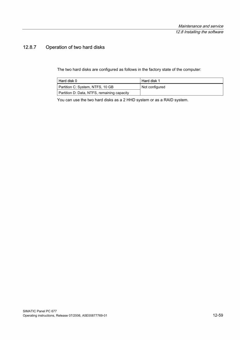
Maintenance and service 12.8 Installing the software
SIMATIC Panel PC 677 Operating instructions, Release 07/2006, A5E00877769-01 12-59
12.8.7 Operation of two hard disks
The two hard disks are configured as follows in the factory state of the computer:
Hard disk 0 Hard disk 1 Partition C: System, NTFS, 10 GB Partition D: Data, NTFS, remaining capacity
Not configured
You can use the two hard disks as a 2 HHD system or as a RAID system.
Maintenance and service 12.8 Installing the software
SIMATIC Panel PC 677 12-60 Operating instructions, Release 07/2006, A5E00877769-01
12.8.7.1 2 HDD system Two 2.5" hard disks are installed in the device depending on the device features. The two hard disks are connected to the SATA ports 0 and 2. The hard disk on SATA port 2 is not configured. This gives you the option of backing up your data to this hard disk. For information on hard disk capacities, refer to your order documentation.
Booting from the slave hard disk The system boots by default from the hard disk on SATA port 0. You can also configure the system to boot from the disk on SATA port 2. In order to allow booting from the second hard disk, you need to configure it as the primary boot device. Make the following settings in your BIOS Setup: Select Boot > Hard Drive > <Drive name> e.g. FUJITSU MHT2060BH - SATA2, then press the "+" key to move it up in the boot order.
Notice The drive letters for the partitions on both drives are assigned by the operating system used. You can change these in the Control Panel as required.
Maintenance and service 12.8 Installing the software
SIMATIC Panel PC 677 Operating instructions, Release 07/2006, A5E00877769-01 12-61
12.8.7.2 RAID system
RAID 0 system A RAID 0 system (Stripe) enables you to increase the read/write speed of your hard disk system. This configuration reduces the reliability of the drive system, however. RAID 0 is therefore not recommended and is omitted from the installation instructions.
RAID 1 system A RAID 1 system (mirroring) enables you to increase the data security of your hard disk system. It involves copying (mirroring) the data to a second hard disk. Each hard disk is operated on a separate SATA channel. The system can continue to operate even when a problem is detected on one of the hard disks. The data backed up on the RAID 1 network is retained. This data would be lost on a single drive or without RAID 1. RAID 1 therefore increases the availability of the system.
Configuring a RAID 1 system
Prerequisites • Two identical SATA hard disks; the primary hard disk contains the operating system and
data (boot drive), the second hard disk is empty. • If DiagMonitor was installed, the DiagMonitor agent must be stopped. To exit the
DiagMonitor agent, enter the command "NET STOP SNMP" in the DOS box. • The Windows XP Professional or Windows 2000 Professional operating system installed
in the factory state already includes the required drivers and the unconfigured RAID software (Intel Matrix Storage Console).
Note Re-starting the DiagMonitor agent After the RAID 1 volume has been sucessfully created, you must start the DiagMonitor agent again. Enter the "NET START SNMP" commands in the DOS box.
Note The screen shots shown below may not correspond to the actual layout of the application.
If the primary hard disk does not have an operating system installed, follow the instructions provided by the section "Restoring the factory state of the software using the Restore DVD".
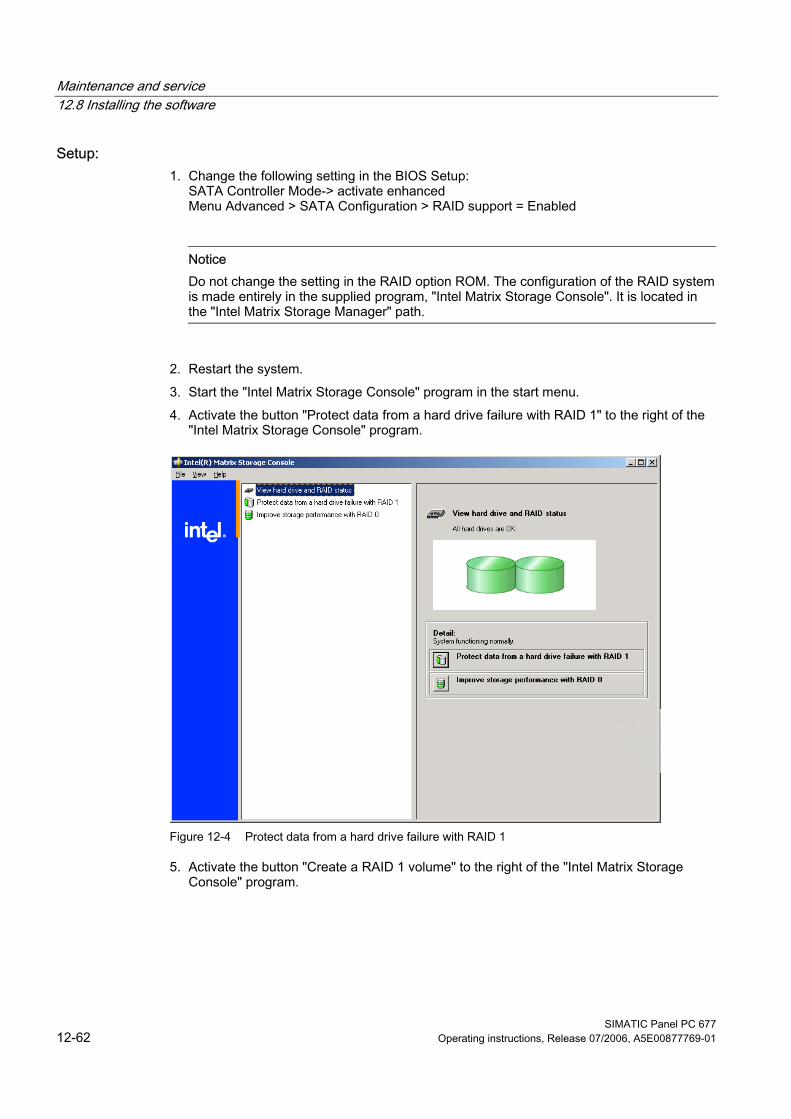
Maintenance and service 12.8 Installing the software
SIMATIC Panel PC 677 12-62 Operating instructions, Release 07/2006, A5E00877769-01
Setup: 1. Change the following setting in the BIOS Setup:
SATA Controller Mode-> activate enhanced Menu Advanced > SATA Configuration > RAID support = Enabled
Notice Do not change the setting in the RAID option ROM. The configuration of the RAID system is made entirely in the supplied program, "Intel Matrix Storage Console". It is located in the "Intel Matrix Storage Manager" path.
2. Restart the system. 3. Start the "Intel Matrix Storage Console" program in the start menu. 4. Activate the button "Protect data from a hard drive failure with RAID 1" to the right of the
"Intel Matrix Storage Console" program.
Figure 12-4 Protect data from a hard drive failure with RAID 1
5. Activate the button "Create a RAID 1 volume" to the right of the "Intel Matrix Storage Console" program.
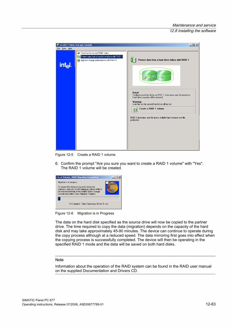
Maintenance and service 12.8 Installing the software
SIMATIC Panel PC 677 Operating instructions, Release 07/2006, A5E00877769-01 12-63
Figure 12-5 Create a RAID 1 volume
6. Confirm the prompt "Are you sure you want to create a RAID 1 volume" with "Yes". The RAID 1 volume will be created.
Figure 12-6 Migration is in Progress
The data on the hard disk specified as the source drive will now be copied to the partner drive. The time required to copy the data (migration) depends on the capacity of the hard disk and may take approximately 45-90 minutes. The device can continue to operate during the copy process although at a reduced speed. The data mirroring first goes into effect when the copying process is successfully completed. The device will then be operating in the specified RAID 1 mode and the data will be saved on both hard disks.
Note Information about the operation of the RAID system can be found in the RAID user manual on the supplied Documentation and Drivers CD.
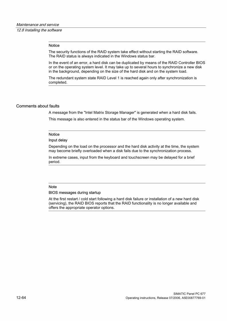
Maintenance and service 12.8 Installing the software
SIMATIC Panel PC 677 12-64 Operating instructions, Release 07/2006, A5E00877769-01
Notice The security functions of the RAID system take effect without starting the RAID software. The RAID status is always indicated in the Windows status bar. In the event of an error, a hard disk can be duplicated by means of the RAID Controller BIOS or on the operating system level. It may take up to several hours to synchronize a new disk in the background, depending on the size of the hard disk and on the system load. The redundant system state RAID Level 1 is reached again only after synchronization is completed.
Comments about faults A message from the "Intel Matrix Storage Manager" is generated when a hard disk fails. This message is also entered in the status bar of the Windows operating system.
Notice Input delay Depending on the load on the processor and the hard disk activity at the time, the system may become briefly overloaded when a disk fails due to the synchronization process. In extreme cases, input from the keyboard and touchscreen may be delayed for a brief period.
Note BIOS messages during startup At the first restart / cold start following a hard disk failure or installation of a new hard disk (servicing), the RAID BIOS reports that the RAID functionality is no longer available and offers the appropriate operator options.
Maintenance and service 12.8 Installing the software
SIMATIC Panel PC 677 Operating instructions, Release 07/2006, A5E00877769-01 12-65
12.8.8 Installing burner and DVD software The supplied CD provides information about installation of the burner and DVD software.
Maintenance and service 12.8 Installing the software
SIMATIC Panel PC 677 12-66 Operating instructions, Release 07/2006, A5E00877769-01
12.8.9 Backing up the hard disk The device's hard disk is divided into two partitions, volumes C and D. The operating system is installed on volume C. Volume D can be used for user data. Back up the complete hard disk regularly, for example, using "SIMATIC PC/PG Image Partition Creator". This software can be purchased as an accessory, Order No. 6ES7648-6AA03-0YX0.
Caution Date errors writing to CD-RW The quality of raw disc differs considerably. Data errors cannot, therefore, be entirely excluded. To be on the safe side, verify the data after writing it.
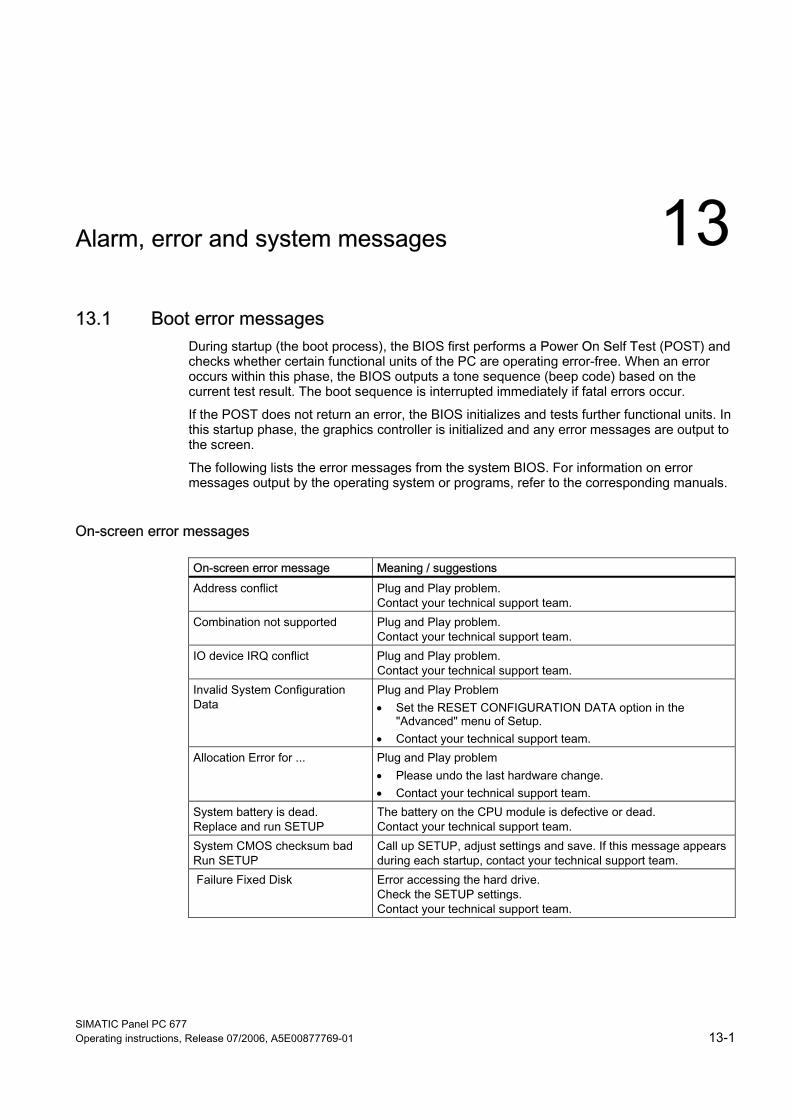
SIMATIC Panel PC 677 Operating instructions, Release 07/2006, A5E00877769-01 13-1
Alarm, error and system messages 1313.1 13.1 Boot error messages
During startup (the boot process), the BIOS first performs a Power On Self Test (POST) and checks whether certain functional units of the PC are operating error-free. When an error occurs within this phase, the BIOS outputs a tone sequence (beep code) based on the current test result. The boot sequence is interrupted immediately if fatal errors occur. If the POST does not return an error, the BIOS initializes and tests further functional units. In this startup phase, the graphics controller is initialized and any error messages are output to the screen. The following lists the error messages from the system BIOS. For information on error messages output by the operating system or programs, refer to the corresponding manuals.
On-screen error messages
On-screen error message Meaning / suggestions Address conflict Plug and Play problem.
Contact your technical support team. Combination not supported Plug and Play problem.
Contact your technical support team. IO device IRQ conflict Plug and Play problem.
Contact your technical support team. Invalid System Configuration Data
Plug and Play Problem • Set the RESET CONFIGURATION DATA option in the
"Advanced" menu of Setup. • Contact your technical support team.
Allocation Error for ... Plug and Play problem • Please undo the last hardware change. • Contact your technical support team.
System battery is dead. Replace and run SETUP
The battery on the CPU module is defective or dead. Contact your technical support team.
System CMOS checksum bad Run SETUP
Call up SETUP, adjust settings and save. If this message appears during each startup, contact your technical support team.
Failure Fixed Disk Error accessing the hard drive. Check the SETUP settings. Contact your technical support team.
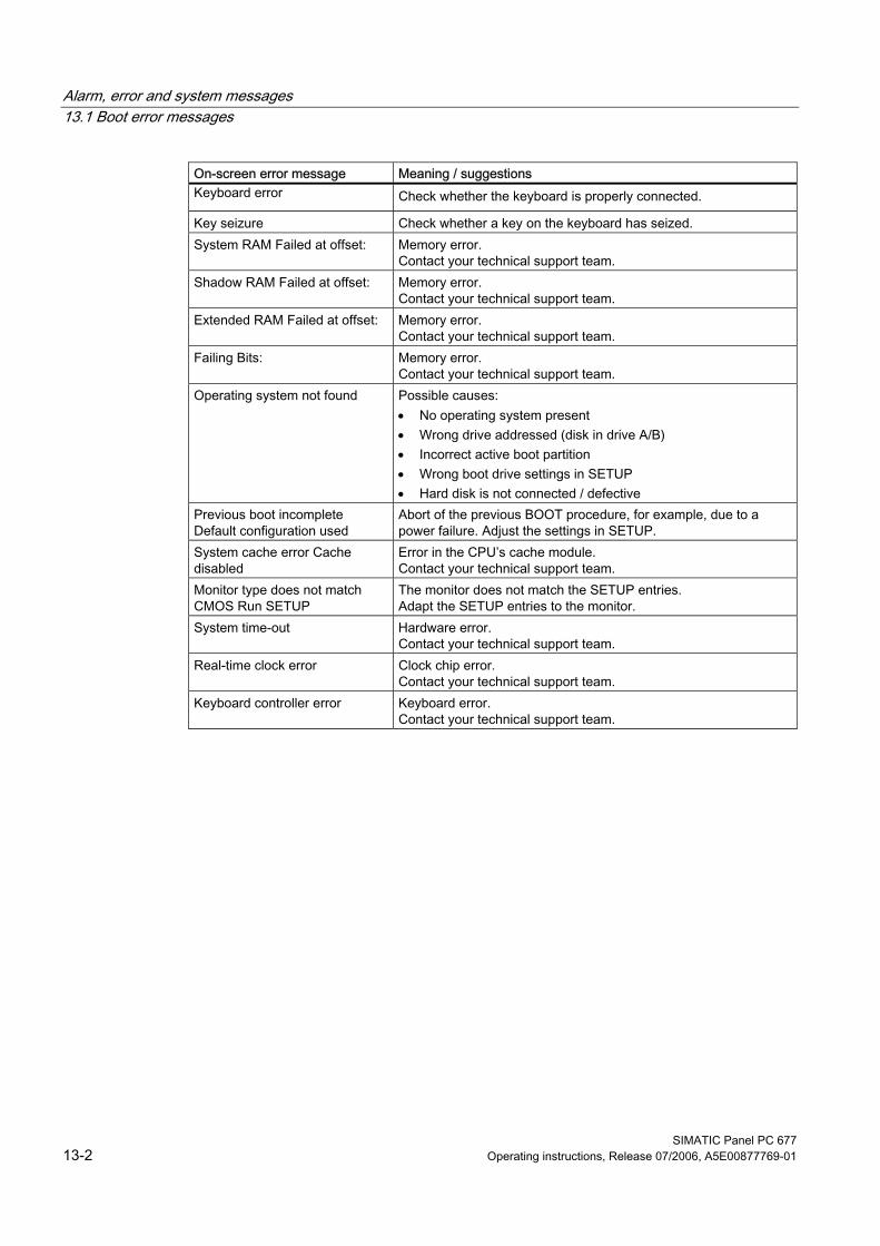
Alarm, error and system messages 13.1 Boot error messages
SIMATIC Panel PC 677 13-2 Operating instructions, Release 07/2006, A5E00877769-01
On-screen error message Meaning / suggestions Keyboard error Check whether the keyboard is properly connected.
Key seizure Check whether a key on the keyboard has seized. System RAM Failed at offset: Memory error.
Contact your technical support team. Shadow RAM Failed at offset: Memory error.
Contact your technical support team. Extended RAM Failed at offset: Memory error.
Contact your technical support team. Failing Bits: Memory error.
Contact your technical support team. Operating system not found Possible causes:
• No operating system present • Wrong drive addressed (disk in drive A/B) • Incorrect active boot partition • Wrong boot drive settings in SETUP • Hard disk is not connected / defective
Previous boot incomplete Default configuration used
Abort of the previous BOOT procedure, for example, due to a power failure. Adjust the settings in SETUP.
System cache error Cache disabled
Error in the CPU’s cache module. Contact your technical support team.
Monitor type does not match CMOS Run SETUP
The monitor does not match the SETUP entries. Adapt the SETUP entries to the monitor.
System time-out Hardware error. Contact your technical support team.
Real-time clock error Clock chip error. Contact your technical support team.
Keyboard controller error Keyboard error. Contact your technical support team.
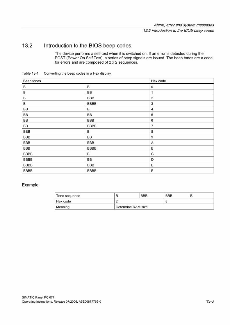
Alarm, error and system messages 13.2 Introduction to the BIOS beep codes
SIMATIC Panel PC 677 Operating instructions, Release 07/2006, A5E00877769-01 13-3
13.2 13.2 Introduction to the BIOS beep codes The device performs a self-test when it is switched on. If an error is detected during the POST (Power On Self Test), a series of beep signals are issued. The beep tones are a code for errors and are composed of 2 x 2 sequences.
Table 13-1 Converting the beep codes in a Hex display
Beep tones Hex code B B 0 B BB 1 B BBB 2 B BBBB 3 BB B 4 BB BB 5 BB BBB 6 BB BBBB 7 BBB B 8 BBB BB 9 BBB BBB A BBB BBBB B BBBB B C BBBB BB D BBBB BBB E BBBB BBBB F
Example
Tone sequence B BBB BBB B Hex code 2 8 Meaning Determine RAM size
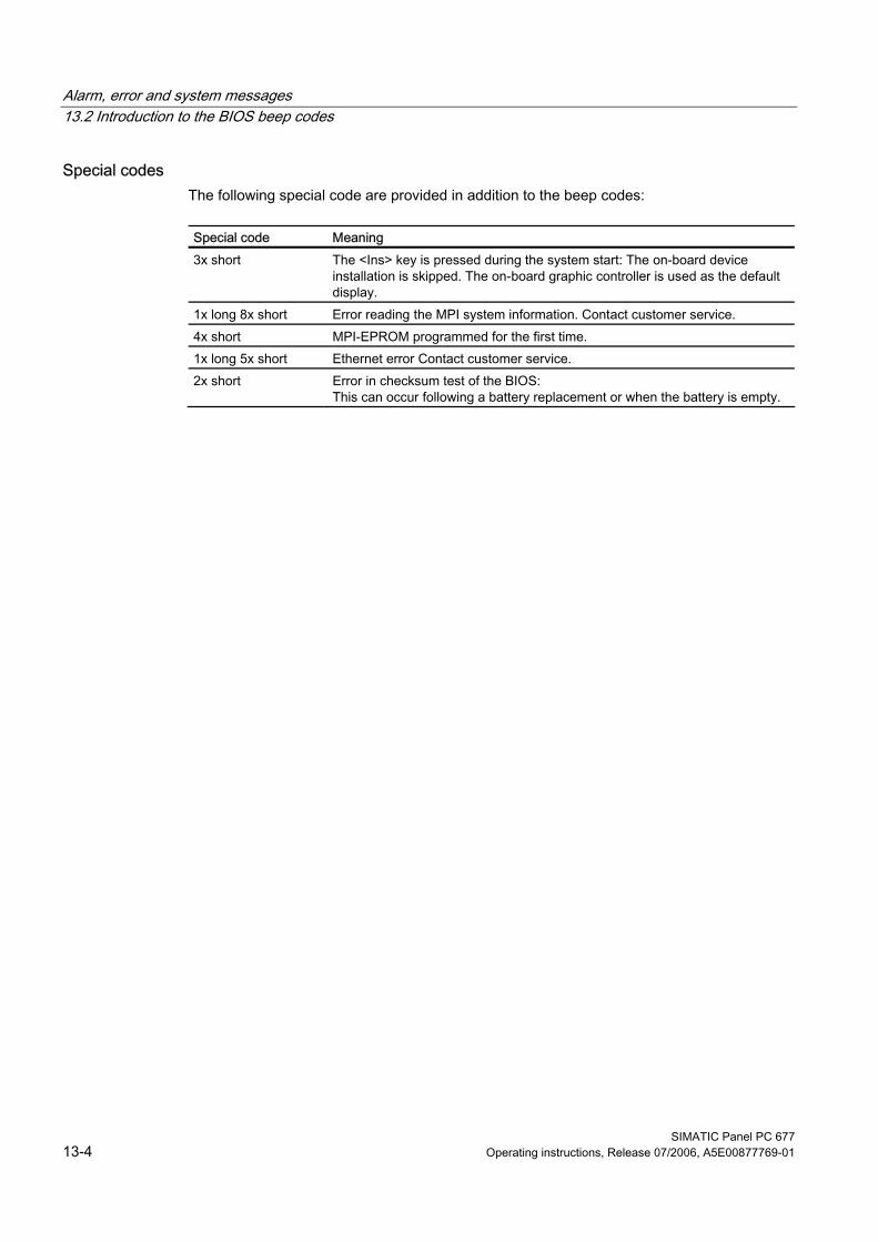
Alarm, error and system messages 13.2 Introduction to the BIOS beep codes
SIMATIC Panel PC 677 13-4 Operating instructions, Release 07/2006, A5E00877769-01
Special codes The following special code are provided in addition to the beep codes:
Special code Meaning 3x short The <Ins> key is pressed during the system start: The on-board device
installation is skipped. The on-board graphic controller is used as the default display.
1x long 8x short Error reading the MPI system information. Contact customer service. 4x short MPI-EPROM programmed for the first time. 1x long 5x short Ethernet error Contact customer service. 2x short Error in checksum test of the BIOS:
This can occur following a battery replacement or when the battery is empty.
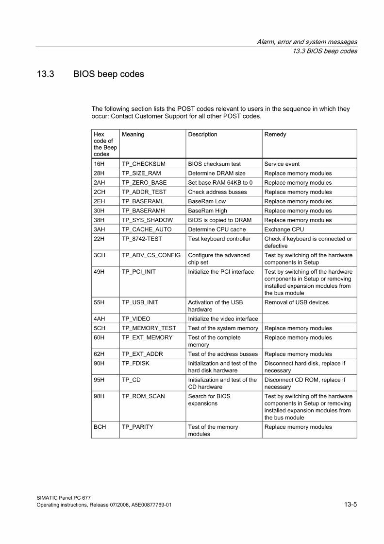
Alarm, error and system messages 13.3 BIOS beep codes
SIMATIC Panel PC 677 Operating instructions, Release 07/2006, A5E00877769-01 13-5
13.3 13.3 BIOS beep codes
The following section lists the POST codes relevant to users in the sequence in which they occur: Contact Customer Support for all other POST codes.
Hex code of the Beep codes
Meaning Description Remedy
16H TP_CHECKSUM BIOS checksum test Service event 28H TP_SIZE_RAM Determine DRAM size Replace memory modules 2AH TP_ZERO_BASE Set base RAM 64KB to 0 Replace memory modules 2CH TP_ADDR_TEST Check address busses Replace memory modules 2EH TP_BASERAML BaseRam Low Replace memory modules 30H TP_BASERAMH BaseRam High Replace memory modules 38H TP_SYS_SHADOW BIOS is copied to DRAM Replace memory modules 3AH TP_CACHE_AUTO Determine CPU cache Exchange CPU 22H TP_8742-TEST Test keyboard controller Check if keyboard is connected or
defective 3CH TP_ADV_CS_CONFIG Configure the advanced
chip set Test by switching off the hardware components in Setup
49H TP_PCI_INIT Initialize the PCI interface Test by switching off the hardware components in Setup or removing installed expansion modules from the bus module
55H TP_USB_INIT Activation of the USB hardware
Removal of USB devices
4AH TP_VIDEO Initialize the video interface 5CH TP_MEMORY_TEST Test of the system memory Replace memory modules 60H TP_EXT_MEMORY Test of the complete
memory Replace memory modules
62H TP_EXT_ADDR Test of the address busses Replace memory modules 90H TP_FDISK Initialization and test of the
hard disk hardware Disconnect hard disk, replace if necessary
95H TP_CD Initialization and test of the CD hardware
Disconnect CD ROM, replace if necessary
98H TP_ROM_SCAN Search for BIOS expansions
Test by switching off the hardware components in Setup or removing installed expansion modules from the bus module
BCH TP_PARITY Test of the memory modules
Replace memory modules
Alarm, error and system messages 13.3 BIOS beep codes
SIMATIC Panel PC 677 13-6 Operating instructions, Release 07/2006, A5E00877769-01
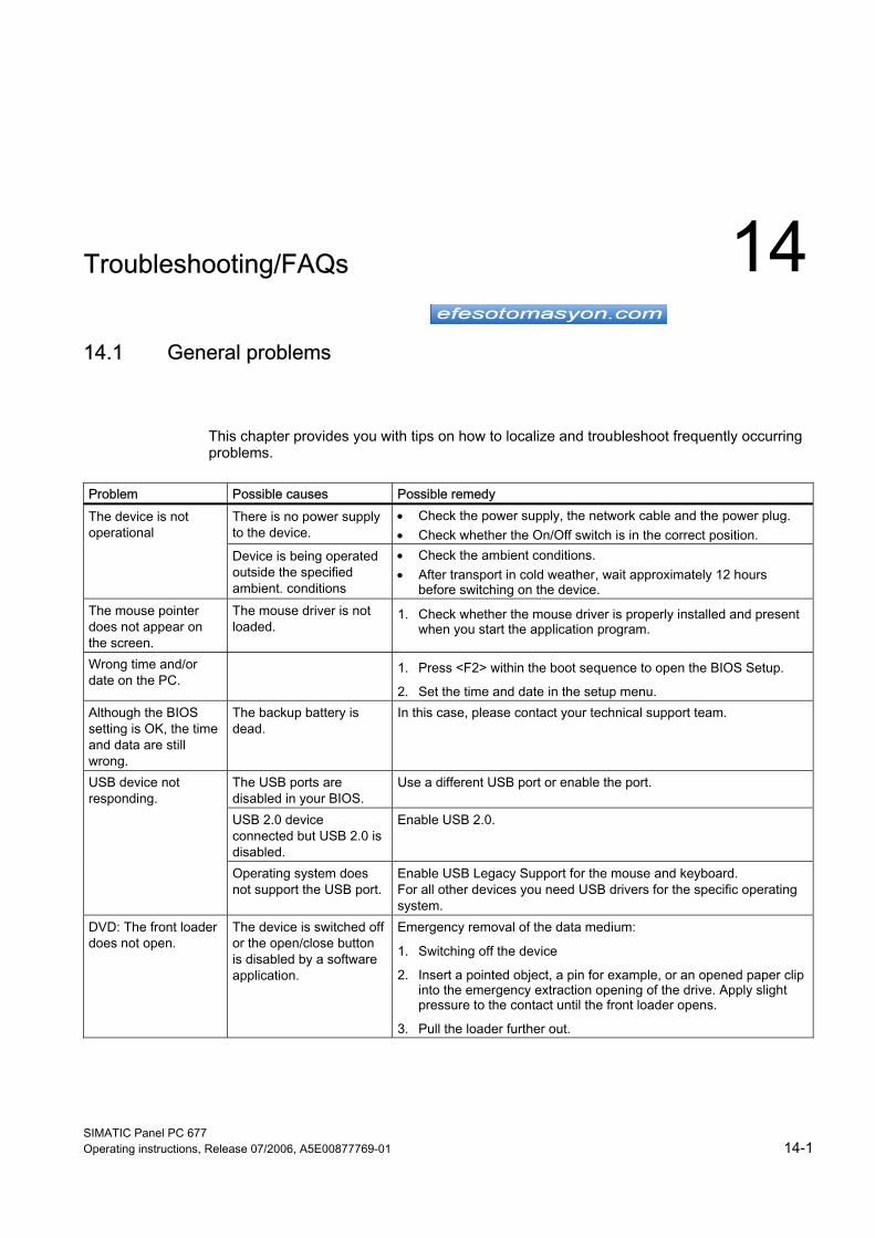
SIMATIC Panel PC 677 Operating instructions, Release 07/2006, A5E00877769-01 14-1
Troubleshooting/FAQs 1414.1 14.1 General problems
This chapter provides you with tips on how to localize and troubleshoot frequently occurring problems.
Problem Possible causes Possible remedy
There is no power supply to the device.
• Check the power supply, the network cable and the power plug. • Check whether the On/Off switch is in the correct position.
The device is not operational
Device is being operated outside the specified ambient. conditions
• Check the ambient conditions. • After transport in cold weather, wait approximately 12 hours
before switching on the device. The mouse pointer does not appear on the screen.
The mouse driver is not loaded.
1. Check whether the mouse driver is properly installed and present when you start the application program.
Wrong time and/or date on the PC.
1. Press <F2> within the boot sequence to open the BIOS Setup.
2. Set the time and date in the setup menu. Although the BIOS setting is OK, the time and data are still wrong.
The backup battery is dead.
In this case, please contact your technical support team.
The USB ports are disabled in your BIOS.
Use a different USB port or enable the port.
USB 2.0 device connected but USB 2.0 is disabled.
Enable USB 2.0.
USB device not responding.
Operating system does not support the USB port.
Enable USB Legacy Support for the mouse and keyboard. For all other devices you need USB drivers for the specific operating system.
DVD: The front loader does not open.
The device is switched off or the open/close button is disabled by a software application.
Emergency removal of the data medium:
1. Switching off the device
2. Insert a pointed object, a pin for example, or an opened paper clip into the emergency extraction opening of the drive. Apply slight pressure to the contact until the front loader opens.
3. Pull the loader further out.
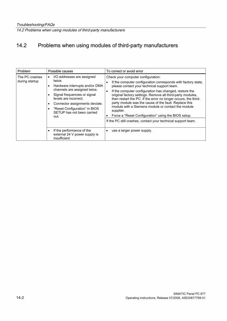
Troubleshooting/FAQs 14.2 Problems when using modules of third-party manufacturers
SIMATIC Panel PC 677 14-2 Operating instructions, Release 07/2006, A5E00877769-01
14.2 14.2 Problems when using modules of third-party manufacturers
Problem Possible causes To correct or avoid error
Check your computer configuration: • If the computer configuration corresponds with factory state,
please contact your technical support team. • If the computer configuration has changed, restore the
original factory settings. Remove all third-party modules, then restart the PC. If the error no longer occurs, the third-party module was the cause of the fault. Replace this module with a Siemens module or contact the module supplier.
• Force a “Reset Configuration” using the BIOS setup.
• I/O addresses are assigned twice.
• Hardware interrupts and/or DMA channels are assigned twice.
• Signal frequencies or signal levels are incorrect.
• Connector assignments deviate. • “Reset Configuration” in BIOS
SETUP has not been carried out.
If the PC still crashes, contact your technical support team.
The PC crashes during startup
• If the performance of the external 24 V power supply is insufficient
• use a larger power supply.
Troubleshooting/FAQs 14.3 Temperature limits
SIMATIC Panel PC 677 Operating instructions, Release 07/2006, A5E00877769-01 14-3
14.3 14.3 Temperature limits
Cause If the device is used for its intended purpose, the temperature threshold values are not exceeded or fallen below. When the LED "Temp" on the upper left side of the operator control unit lights up, check the following: • Are the fan apertures covered? • Has the fan failed (check speed display in the SOM or on the DiagMonitor)? • Is the ambient temperature higher than the allowed value (see "Technical data")? • Is the total output of the power supply within the specified limit? • Are the heatsinks inside the PC covered with dust?
Remedy The temperature error is retained until the temperatures have fallen below the thresholds and you have acknowledged the error alarm in the SOM program. Click on the button with the "small broom" icon. When the error alarm has been acknowledged, the "TEMP" LED on the devices goes off and the title bar and "SOM" icon in the status bar of the SOM program changes from red to green. If you have not installed the SOM program or DiagMonitor, you must restart the PC.

Troubleshooting/FAQs 14.3 Temperature limits
SIMATIC Panel PC 677 14-4 Operating instructions, Release 07/2006, A5E00877769-01
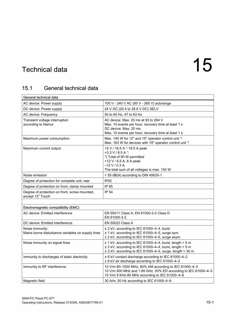
SIMATIC Panel PC 677 Operating instructions, Release 07/2006, A5E00877769-01 15-1
Technical data 1515.1 15.1 General technical data General technical data AC device: Power supply 100 V - 240 V AC (85 V - 265 V) autorange DC device: Power supply 24 V DC (20.4 to 28.8 V DC) SELV AC device: Frequency 50 to 60 Hz, 47 to 63 Hz Transient voltage interruption according to Namur
AC device: Max. 20 ms at 93 to 264 V Max. 10 events per hour; recovery time at least 1 s DC device: Max. 20 ms Max. 10 events per hour; recovery time at least 1 s
Maximum power consumption Max. 140 W for 12" and 15" operator control unit 1) Max. 163 W for devices with 19" operator control unit 1)
Maximum current output +5 V / 16.5 A *), 18.5 A peak +3.3 V / 8.5 A *) *) Total of 90 W permitted +12 V / 6.5 A, 8 A peak –12 V / 0.3 A The total sum of all voltages is max. 150 W
Noise emission < 55 dB(A) according to DIN 45635-1 Degree of protection for complete unit, rear IP20 Degree of protection on front, clamp mounted IP 65 Degree of protection on front, screw mounted, except 12" Touch
IP 54
Electromagnetic compatibility (EMC) AC device: Emitted interference EN 55011 Class A, EN 61000-3-2 Class D
EN 61000-3-3 DC device: Emitted interference EN 55022 Class A Noise immunity: Mains borne disturbance variables on supply lines
± 2 kV, according to IEC 61000–4–4, burst ± 1 kV, according to IEC 61000–4–5, surge sym. ± 2 kV, according to IEC 61000–4–5, surge asym.
Noise immunity on signal lines ± 1 kV, according to IEC 61000–4–4, burst, length < 5 m ± 2 kV, according to IEC 61000–4–4, burst, length > 5 m ± 2 kV, according to IEC 61000–4–5, surge, length > 30 m
Immunity to discharges of static electricity ± 6 kV contact discharge according to IEC 61000–4–2 ± 8 kV air discharge according to IEC 61000–4–2
Immunity to RF interference 10 V/m 80–1000 MHz, 80% AM according to IEC 61000–4–3 10 V/m 900 MHz and 1.89 GHz, 50% ED according to IEC 61000–4–310 V/m 9 KHz-80 MHz according to IEC 61000–4–6
Magnetic field 30 A/m, 50 Hz according to IEC 61000–4–8
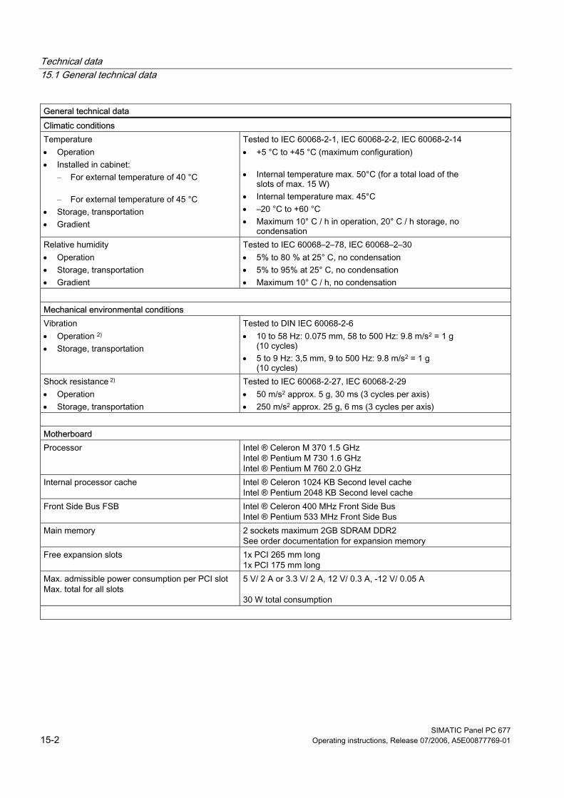
Technical data 15.1 General technical data
SIMATIC Panel PC 677 15-2 Operating instructions, Release 07/2006, A5E00877769-01
General technical data Climatic conditions Temperature • Operation • Installed in cabinet:
– For external temperature of 40 °C
– For external temperature of 45 °C • Storage, transportation • Gradient
Tested to IEC 60068-2-1, IEC 60068-2-2, IEC 60068-2-14 • +5 °C to +45 °C (maximum configuration)
• Internal temperature max. 50°C (for a total load of the
slots of max. 15 W) • Internal temperature max. 45°C • –20 °C to +60 °C • Maximum 10° C / h in operation, 20° C / h storage, no
condensation Relative humidity • Operation • Storage, transportation • Gradient
Tested to IEC 60068–2–78, IEC 60068–2–30 • 5% to 80 % at 25° C, no condensation • 5% to 95% at 25° C, no condensation • Maximum 10° C / h, no condensation
Mechanical environmental conditions Vibration • Operation 2) • Storage, transportation
Tested to DIN IEC 60068-2-6 • 10 to 58 Hz: 0.075 mm, 58 to 500 Hz: 9.8 m/s2 = 1 g
(10 cycles) • 5 to 9 Hz: 3,5 mm, 9 to 500 Hz: 9.8 m/s2 = 1 g
(10 cycles) Shock resistance 2) • Operation • Storage, transportation
Tested to IEC 60068-2-27, IEC 60068-2-29 • 50 m/s2 approx. 5 g, 30 ms (3 cycles per axis) • 250 m/s2 approx. 25 g, 6 ms (3 cycles per axis)
Motherboard Processor Intel ® Celeron M 370 1.5 GHz
Intel ® Pentium M 730 1.6 GHz Intel ® Pentium M 760 2.0 GHz
Internal processor cache Intel ® Celeron 1024 KB Second level cache Intel ® Pentium 2048 KB Second level cache
Front Side Bus FSB Intel ® Celeron 400 MHz Front Side Bus Intel ® Pentium 533 MHz Front Side Bus
Main memory 2 sockets maximum 2GB SDRAM DDR2 See order documentation for expansion memory
Free expansion slots 1x PCI 265 mm long 1x PCI 175 mm long
Max. admissible power consumption per PCI slot Max. total for all slots
5 V/ 2 A or 3.3 V/ 2 A, 12 V/ 0.3 A, -12 V/ 0.05 A 30 W total consumption
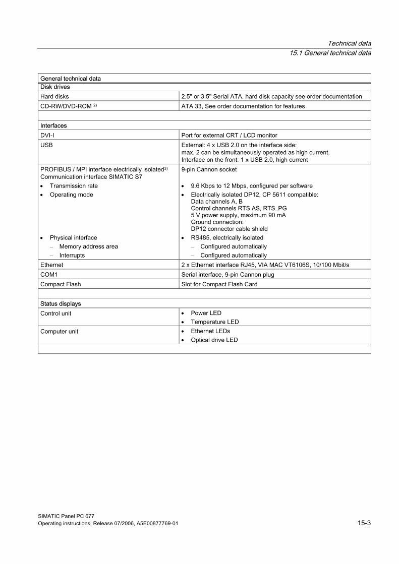
Technical data 15.1 General technical data
SIMATIC Panel PC 677 Operating instructions, Release 07/2006, A5E00877769-01 15-3
General technical data Disk drives Hard disks 2.5'' or 3.5'' Serial ATA, hard disk capacity see order documentation CD-RW/DVD-ROM 2) ATA 33, See order documentation for features Interfaces DVI-I Port for external CRT / LCD monitor USB External: 4 x USB 2.0 on the interface side:
max. 2 can be simultaneously operated as high current. Interface on the front: 1 x USB 2.0, high current
PROFIBUS / MPI interface electrically isolated3) Communication interface SIMATIC S7 • Transmission rate • Operating mode
• Physical interface – Memory address area – Interrupts
9-pin Cannon socket • 9.6 Kbps to 12 Mbps, configured per software • Electrically isolated DP12, CP 5611 compatible:
Data channels A, B Control channels RTS AS, RTS_PG 5 V power supply, maximum 90 mA Ground connection: DP12 connector cable shield
• RS485, electrically isolated – Configured automatically – Configured automatically
Ethernet 2 x Ethernet interface RJ45, VIA MAC VT6106S, 10/100 Mbit/s COM1 Serial interface, 9-pin Cannon plug Compact Flash Slot for Compact Flash Card Status displays Control unit • Power LED
• Temperature LED Computer unit • Ethernet LEDs
• Optical drive LED
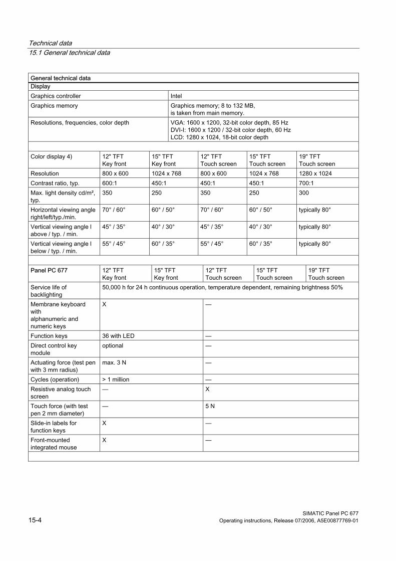
Technical data 15.1 General technical data
SIMATIC Panel PC 677 15-4 Operating instructions, Release 07/2006, A5E00877769-01
General technical data Display Graphics controller Intel Graphics memory Graphics memory; 8 to 132 MB,
is taken from main memory. Resolutions, frequencies, color depth VGA: 1600 x 1200, 32-bit color depth, 85 Hz
DVI-I: 1600 x 1200 / 32-bit color depth, 60 Hz LCD: 1280 x 1024, 18-bit color depth
Color display 4) 12" TFT
Key front 15" TFT Key front
12" TFT Touch screen
15" TFT Touch screen
19" TFT Touch screen
Resolution 800 x 600 1024 x 768 800 x 600 1024 x 768 1280 x 1024 Contrast ratio, typ. 600:1 450:1 450:1 450:1 700:1 Max. light density cd/m², typ.
350 250 350 250 300
Horizontal viewing angle right/left/typ./min.
70° / 60° 60° / 50° 70° / 60° 60° / 50° typically 80°
Vertical viewing angle l above / typ. / min.
45° / 35° 40° / 30° 45° / 35° 40° / 30° typically 80°
Vertical viewing angle l below / typ. / min.
55° / 45° 60° / 35° 55° / 45° 60° / 35° typically 80°
Panel PC 677 12" TFT
Key front 15" TFT Key front
12" TFT Touch screen
15" TFT Touch screen
19" TFT Touch screen
Service life of backlighting
50,000 h for 24 h continuous operation, temperature dependent, remaining brightness 50%
Membrane keyboard with alphanumeric and numeric keys
X —
Function keys 36 with LED — Direct control key module
optional —
Actuating force (test pen with 3 mm radius)
max. 3 N —
Cycles (operation) > 1 million — Resistive analog touch screen
— X
Touch force (with test pen 2 mm diameter)
— 5 N
Slide-in labels for function keys
X —
Front-mounted integrated mouse
X —
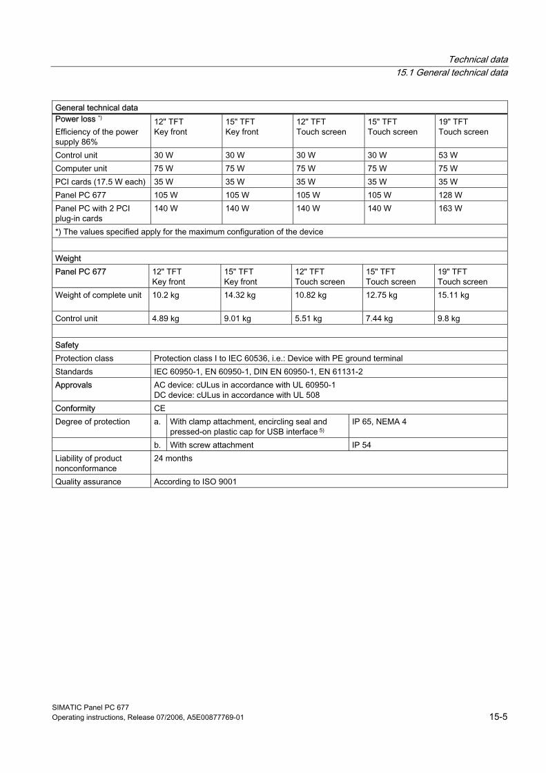
Technical data 15.1 General technical data
SIMATIC Panel PC 677 Operating instructions, Release 07/2006, A5E00877769-01 15-5
General technical data Power loss *) Efficiency of the power supply 86%
12" TFT Key front
15" TFT Key front
12" TFT Touch screen
15" TFT Touch screen
19" TFT Touch screen
Control unit 30 W 30 W 30 W 30 W 53 W Computer unit 75 W 75 W 75 W 75 W 75 W PCI cards (17.5 W each) 35 W 35 W 35 W 35 W 35 W Panel PC 677 105 W 105 W 105 W 105 W 128 W Panel PC with 2 PCI plug-in cards
140 W 140 W 140 W 140 W 163 W
*) The values specified apply for the maximum configuration of the device Weight Panel PC 677 12" TFT
Key front 15" TFT Key front
12" TFT Touch screen
15" TFT Touch screen
19" TFT Touch screen
Weight of complete unit
10.2 kg 14.32 kg 10.82 kg 12.75 kg 15.11 kg
Control unit 4.89 kg 9.01 kg 5.51 kg 7.44 kg 9.8 kg Safety Protection class Protection class I to IEC 60536, i.e.: Device with PE ground terminal Standards IEC 60950-1, EN 60950-1, DIN EN 60950-1, EN 61131-2 Approvals AC device: cULus in accordance with UL 60950-1
DC device: cULus in accordance with UL 508 Conformity CE Degree of protection a. With clamp attachment, encircling seal and
pressed-on plastic cap for USB interface 5) IP 65, NEMA 4
b. With screw attachment IP 54 Liability of product nonconformance
24 months
Quality assurance According to ISO 9001
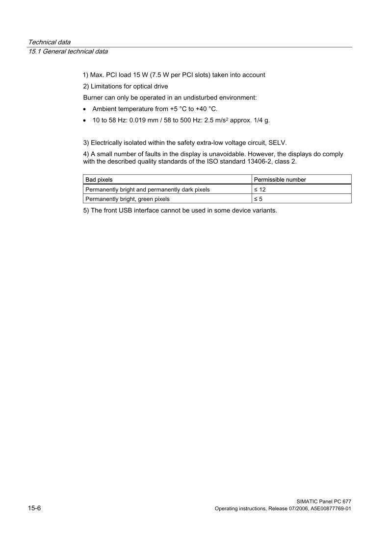
Technical data 15.1 General technical data
SIMATIC Panel PC 677 15-6 Operating instructions, Release 07/2006, A5E00877769-01
1) Max. PCI load 15 W (7.5 W per PCI slots) taken into account 2) Limitations for optical drive Burner can only be operated in an undisturbed environment: • Ambient temperature from +5 °C to +40 °C. • 10 to 58 Hz: 0.019 mm / 58 to 500 Hz: 2.5 m/s2 approx. 1/4 g. 3) Electrically isolated within the safety extra-low voltage circuit, SELV. 4) A small number of faults in the display is unavoidable. However, the displays do comply with the described quality standards of the ISO standard 13406-2, class 2.
Bad pixels Permissible number Permanently bright and permanently dark pixels ≤ 12 Permanently bright, green pixels ≤ 5
5) The front USB interface cannot be used in some device variants.
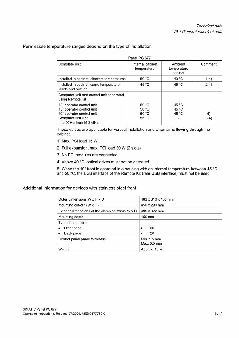
Technical data 15.1 General technical data
SIMATIC Panel PC 677 Operating instructions, Release 07/2006, A5E00877769-01 15-7
Permissible temperature ranges depend on the type of installation
Panel PC 677 Complete unit Internal cabinet
temperature Ambient
temperature cabinet
Comment
Installed in cabinet, different temperatures 50 °C 40 °C 1)4) Installed in cabinet, same temperature inside and outside
45 °C 45 °C 2)4)
Computer unit and control unit separated, using Remote Kit 12" operator control unit 15" operator control unit 19" operator control unit Computer unit 677, Intel ® Pentium M 2 GHz
50 °C 50 °C 50 °C 55 °C
45 °C 45 °C 45 °C
-
5) 3)4)
These values are applicable for vertical installation and when air is flowing through the cabinet. 1) Max. PCI load 15 W 2) Full expansion, max. PCI load 30 W (2 slots) 3) No PCI modules are connected 4) Above 40 °C, optical drives must not be operated 5) When the 19" front is operated in a housing with an internal temperature between 45 °C and 50 °C, the USB interface of the Remote Kit (rear USB interface) must not be used.
Additional information for devices with stainless steel front
Outer dimensions W x H x D 483 x 310 x 155 mm Mounting cut-out (W x H) 450 x 290 mm Exterior dimensions of the clamping frame W x H 495 x 322 mm Mounting depth 150 mm Type of protection • Front panel • Back page
• IP66 • IP20
Control panel panel thickness Min. 1.5 mm Max. 5,0 mm
Weight Approx. 15 kg
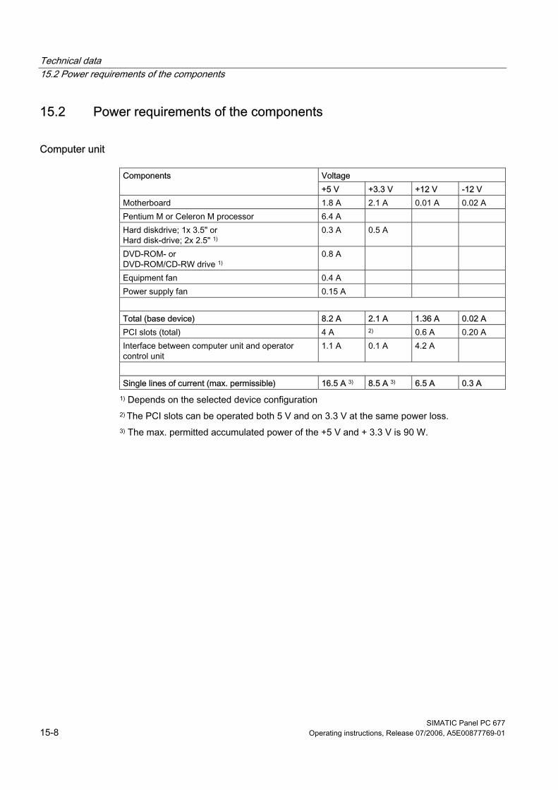
Technical data 15.2 Power requirements of the components
SIMATIC Panel PC 677 15-8 Operating instructions, Release 07/2006, A5E00877769-01
15.2 15.2 Power requirements of the components
Computer unit
Voltage Components +5 V +3.3 V +12 V -12 V
Motherboard 1.8 A 2.1 A 0.01 A 0.02 A Pentium M or Celeron M processor 6.4 A Hard diskdrive; 1x 3.5" or Hard disk-drive; 2x 2.5" 1)
0.3 A 0.5 A
DVD-ROM- or DVD-ROM/CD-RW drive 1)
0.8 A
Equipment fan 0.4 A Power supply fan 0.15 A Total (base device) 8.2 A 2.1 A 1.36 A 0.02 A PCI slots (total) 4 A 2) 0.6 A 0.20 A Interface between computer unit and operator control unit
1.1 A 0.1 A 4.2 A
Single lines of current (max. permissible) 16.5 A 3) 8.5 A 3) 6.5 A 0.3 A
1) Depends on the selected device configuration 2) The PCI slots can be operated both 5 V and on 3.3 V at the same power loss. 3) The max. permitted accumulated power of the +5 V and + 3.3 V is 90 W.
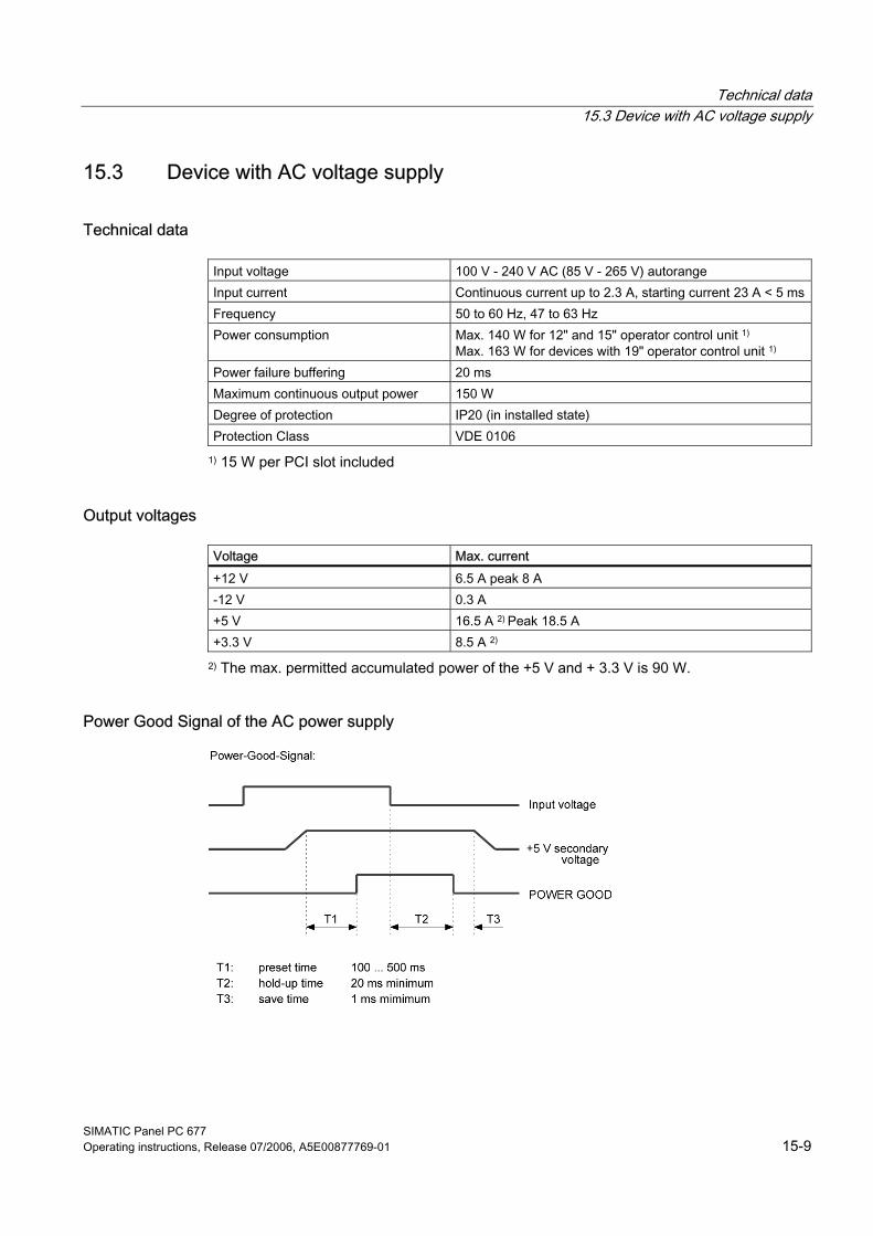
Technical data 15.3 Device with AC voltage supply
SIMATIC Panel PC 677 Operating instructions, Release 07/2006, A5E00877769-01 15-9
15.3 15.3 Device with AC voltage supply
Technical data
Input voltage 100 V - 240 V AC (85 V - 265 V) autorange Input current Continuous current up to 2.3 A, starting current 23 A < 5 msFrequency 50 to 60 Hz, 47 to 63 Hz Power consumption Max. 140 W for 12" and 15" operator control unit 1)
Max. 163 W for devices with 19" operator control unit 1) Power failure buffering 20 ms Maximum continuous output power 150 W Degree of protection IP20 (in installed state) Protection Class VDE 0106
1) 15 W per PCI slot included
Output voltages
Voltage Max. current +12 V 6.5 A peak 8 A -12 V 0.3 A +5 V 16.5 A 2) Peak 18.5 A +3.3 V 8.5 A 2)
2) The max. permitted accumulated power of the +5 V and + 3.3 V is 90 W.
Power Good Signal of the AC power supply
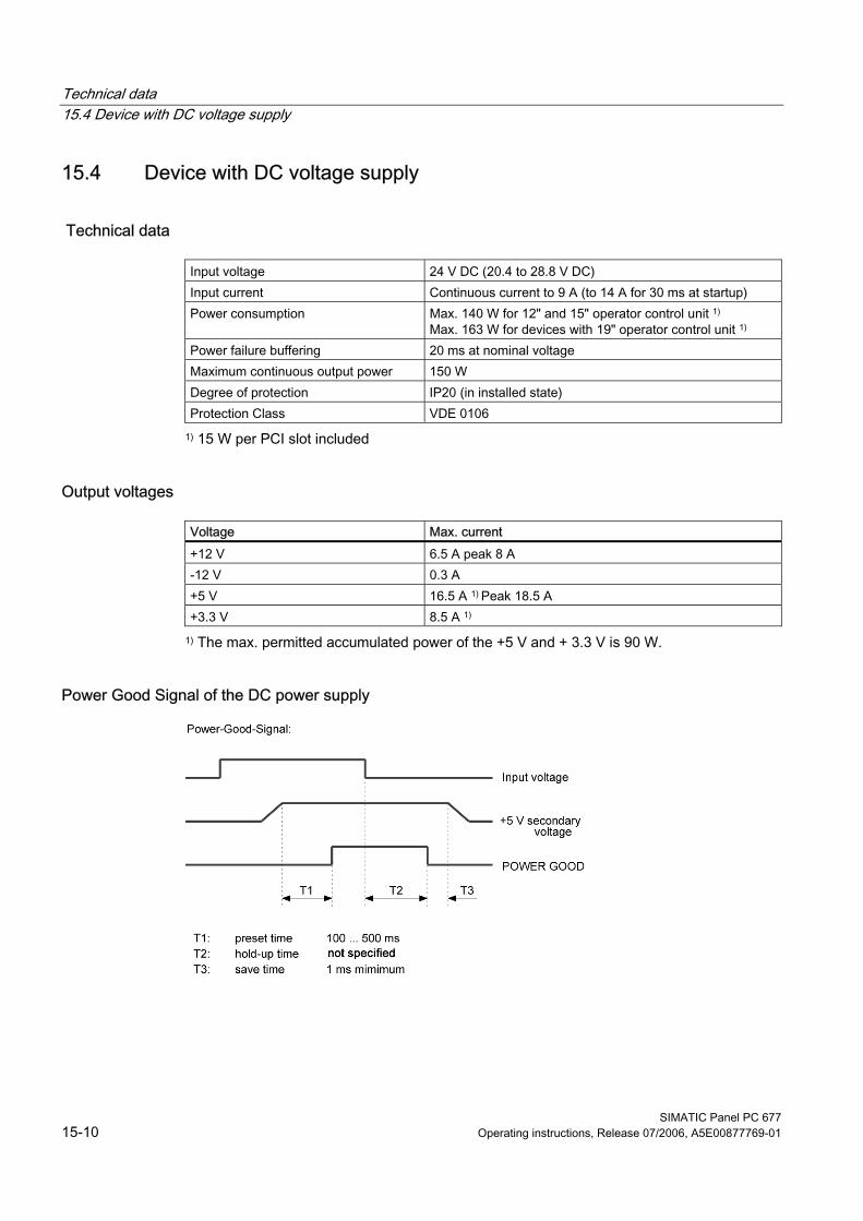
Technical data 15.4 Device with DC voltage supply
SIMATIC Panel PC 677 15-10 Operating instructions, Release 07/2006, A5E00877769-01
15.4 15.4 Device with DC voltage supply
Technical data
Input voltage 24 V DC (20.4 to 28.8 V DC) Input current Continuous current to 9 A (to 14 A for 30 ms at startup) Power consumption Max. 140 W for 12" and 15" operator control unit 1)
Max. 163 W for devices with 19" operator control unit 1) Power failure buffering 20 ms at nominal voltage Maximum continuous output power 150 W Degree of protection IP20 (in installed state) Protection Class VDE 0106
1) 15 W per PCI slot included
Output voltages
Voltage Max. current +12 V 6.5 A peak 8 A -12 V 0.3 A +5 V 16.5 A 1) Peak 18.5 A +3.3 V 8.5 A 1)
1) The max. permitted accumulated power of the +5 V and + 3.3 V is 90 W.
Power Good Signal of the DC power supply
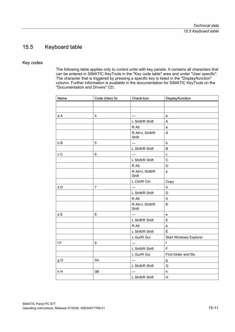
Technical data 15.5 Keyboard table
SIMATIC Panel PC 677 Operating instructions, Release 07/2006, A5E00877769-01 15-11
15.5 15.5 Keyboard table
Key codes The following table applies only to control units with key panels. It contains all characters that can be entered in SIMATIC KeyTools in the "Key code table" area and under "User specific". The character that is triggered by pressing a specific key is listed in the "Display/function" column. Further information is available in the documentation for SIMATIC KeyTools on the "Documentation and Drivers" CD.
Name Code (Hex) 0x Check-box Display/function a A 4 — a L Shift/R Shift A R Alt á R Alt+L Shift/R
Shift Á
b B 5 — b L Shift/R Shift B c C 6 — c L Shift/R Shift C R Alt © R Alt+L Shift/R
Shift ¢
L Ctrl/R Ctrl Copy d D 7 — d L Shift/R Shift D R Alt ð R Alt+L Shift/R
Shift Ð
e E 8 — e L Shift/R Shift E R Alt é L Shift/R Shift É L Gui/R Gui Start Windows Explorer f F 9 — f L Shift/R Shift F L Gui/R Gui Find folder and file g G 0A — g L Shift/R Shift G h H 0B — h L Shift/R Shift H
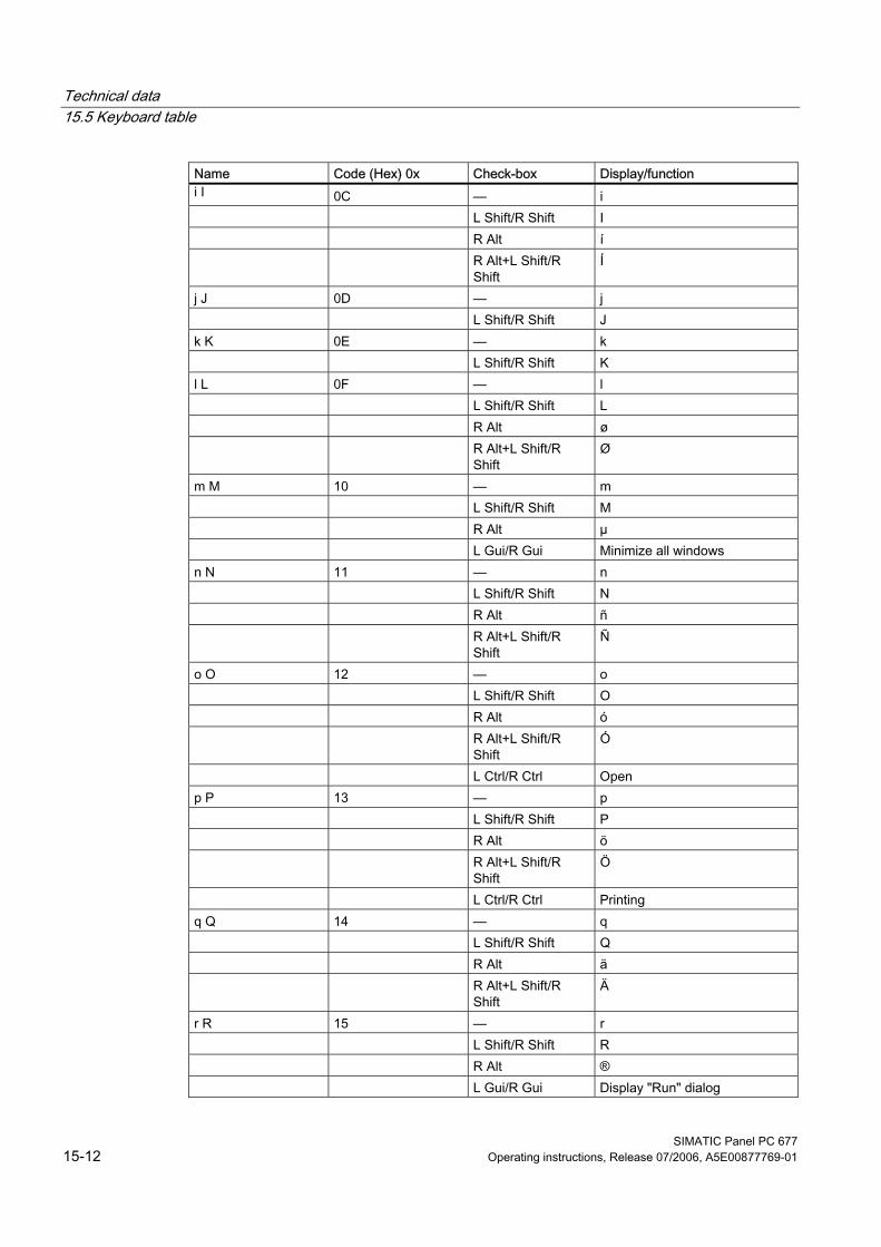
Technical data 15.5 Keyboard table
SIMATIC Panel PC 677 15-12 Operating instructions, Release 07/2006, A5E00877769-01
Name Code (Hex) 0x Check-box Display/function i I 0C — i L Shift/R Shift I R Alt í R Alt+L Shift/R
Shift Í
j J 0D — j L Shift/R Shift J k K 0E — k L Shift/R Shift K l L 0F — l L Shift/R Shift L R Alt ø R Alt+L Shift/R
Shift Ø
m M 10 — m L Shift/R Shift M R Alt µ L Gui/R Gui Minimize all windows n N 11 — n L Shift/R Shift N R Alt ñ R Alt+L Shift/R
Shift Ñ
o O 12 — o L Shift/R Shift O R Alt ó R Alt+L Shift/R
Shift Ó
L Ctrl/R Ctrl Open p P 13 — p L Shift/R Shift P R Alt ö R Alt+L Shift/R
Shift Ö
L Ctrl/R Ctrl Printing q Q 14 — q L Shift/R Shift Q R Alt ä R Alt+L Shift/R
Shift Ä
r R 15 — r L Shift/R Shift R R Alt ® L Gui/R Gui Display "Run" dialog
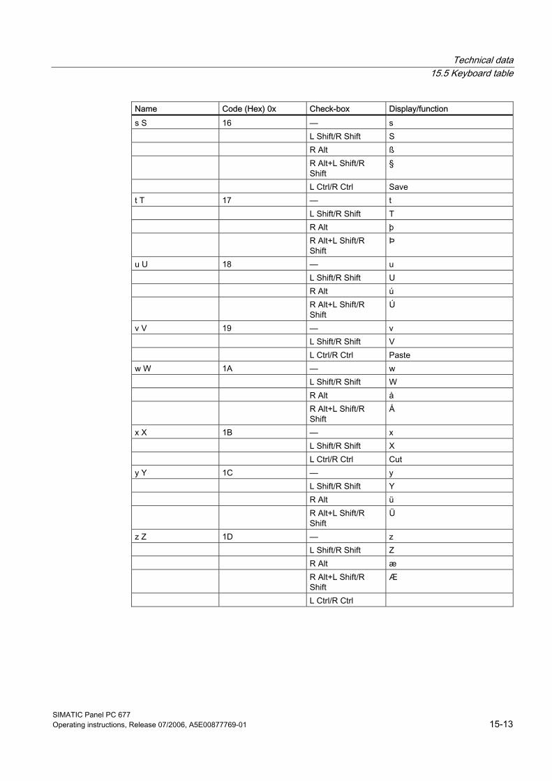
Technical data 15.5 Keyboard table
SIMATIC Panel PC 677 Operating instructions, Release 07/2006, A5E00877769-01 15-13
Name Code (Hex) 0x Check-box Display/function s S 16 — s L Shift/R Shift S R Alt ß R Alt+L Shift/R
Shift §
L Ctrl/R Ctrl Save t T 17 — t L Shift/R Shift T R Alt þ R Alt+L Shift/R
Shift Þ
u U 18 — u L Shift/R Shift U R Alt ú R Alt+L Shift/R
Shift Ú
v V 19 — v L Shift/R Shift V L Ctrl/R Ctrl Paste w W 1A — w L Shift/R Shift W R Alt å R Alt+L Shift/R
Shift Å
x X 1B — x L Shift/R Shift X L Ctrl/R Ctrl Cut y Y 1C — y L Shift/R Shift Y R Alt ü R Alt+L Shift/R
Shift Ü
z Z 1D — z L Shift/R Shift Z R Alt æ R Alt+L Shift/R
Shift Æ
L Ctrl/R Ctrl
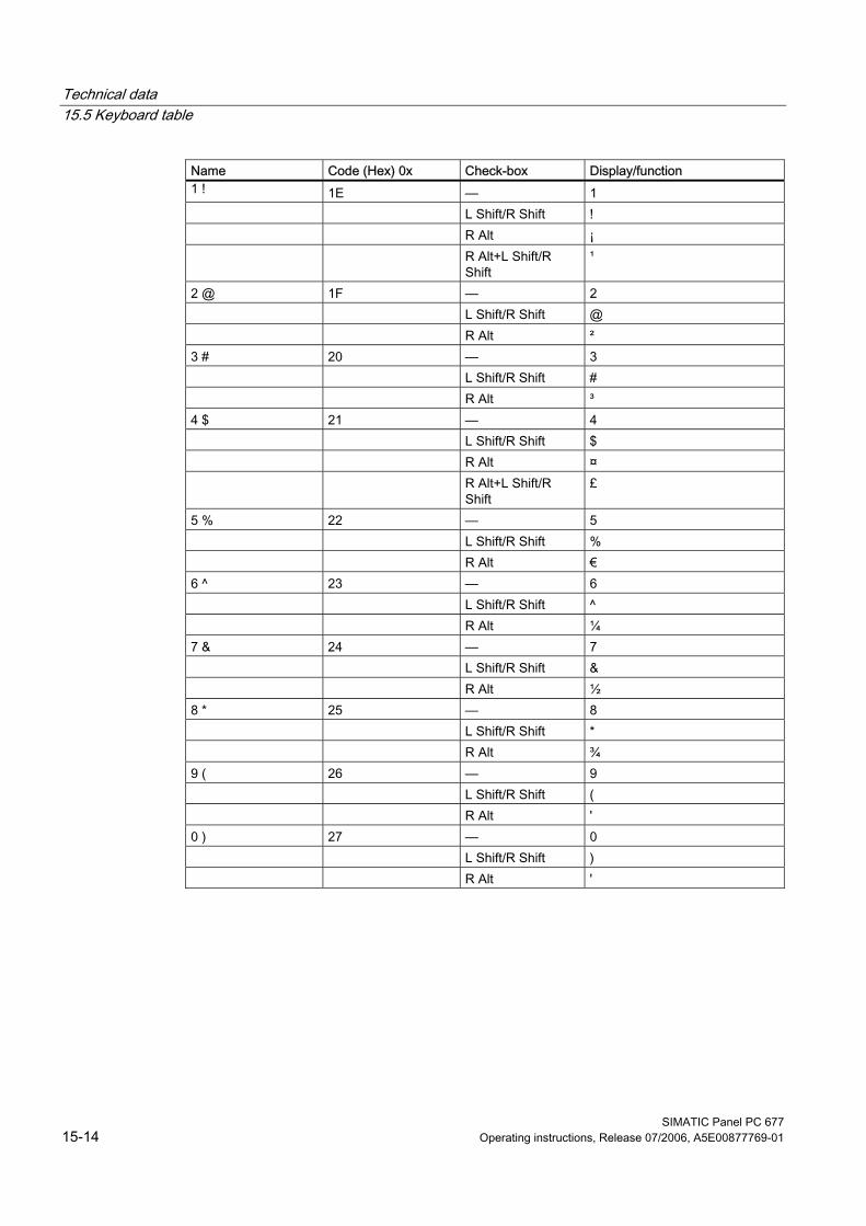
Technical data 15.5 Keyboard table
SIMATIC Panel PC 677 15-14 Operating instructions, Release 07/2006, A5E00877769-01
Name Code (Hex) 0x Check-box Display/function 1 ! 1E — 1 L Shift/R Shift ! R Alt ¡ R Alt+L Shift/R
Shift ¹
2 @ 1F — 2 L Shift/R Shift @ R Alt ² 3 # 20 — 3 L Shift/R Shift # R Alt ³ 4 $ 21 — 4 L Shift/R Shift $ R Alt ¤ R Alt+L Shift/R
Shift £
5 % 22 — 5 L Shift/R Shift % R Alt € 6 ^ 23 — 6 L Shift/R Shift ^ R Alt ¼ 7 & 24 — 7 L Shift/R Shift & R Alt ½ 8 * 25 — 8 L Shift/R Shift * R Alt ¾ 9 ( 26 — 9 L Shift/R Shift ( R Alt ' 0 ) 27 — 0 L Shift/R Shift ) R Alt '
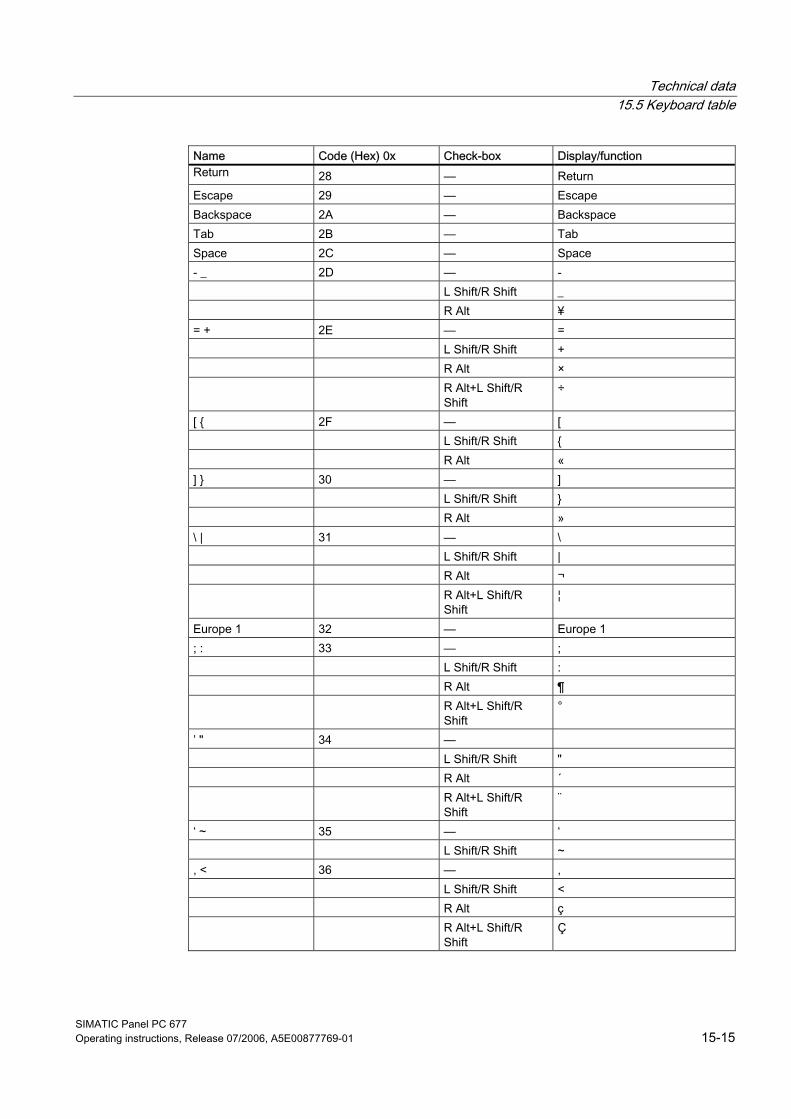
Technical data 15.5 Keyboard table
SIMATIC Panel PC 677 Operating instructions, Release 07/2006, A5E00877769-01 15-15
Name Code (Hex) 0x Check-box Display/function Return 28 — Return Escape 29 — Escape Backspace 2A — Backspace Tab 2B — Tab Space 2C — Space - _ 2D — - L Shift/R Shift _ R Alt ¥ = + 2E — = L Shift/R Shift + R Alt × R Alt+L Shift/R
Shift ÷
[ { 2F — [ L Shift/R Shift { R Alt « ] } 30 — ] L Shift/R Shift } R Alt » \ | 31 — \ L Shift/R Shift | R Alt ¬ R Alt+L Shift/R
Shift ¦
Europe 1 32 — Europe 1 ; : 33 — ; L Shift/R Shift : R Alt ¶ R Alt+L Shift/R
Shift °
’ " 34 — L Shift/R Shift " R Alt ´ R Alt+L Shift/R
Shift ¨
‘ ~ 35 — ‘ L Shift/R Shift ~ , < 36 — , L Shift/R Shift < R Alt ç R Alt+L Shift/R
Shift Ç
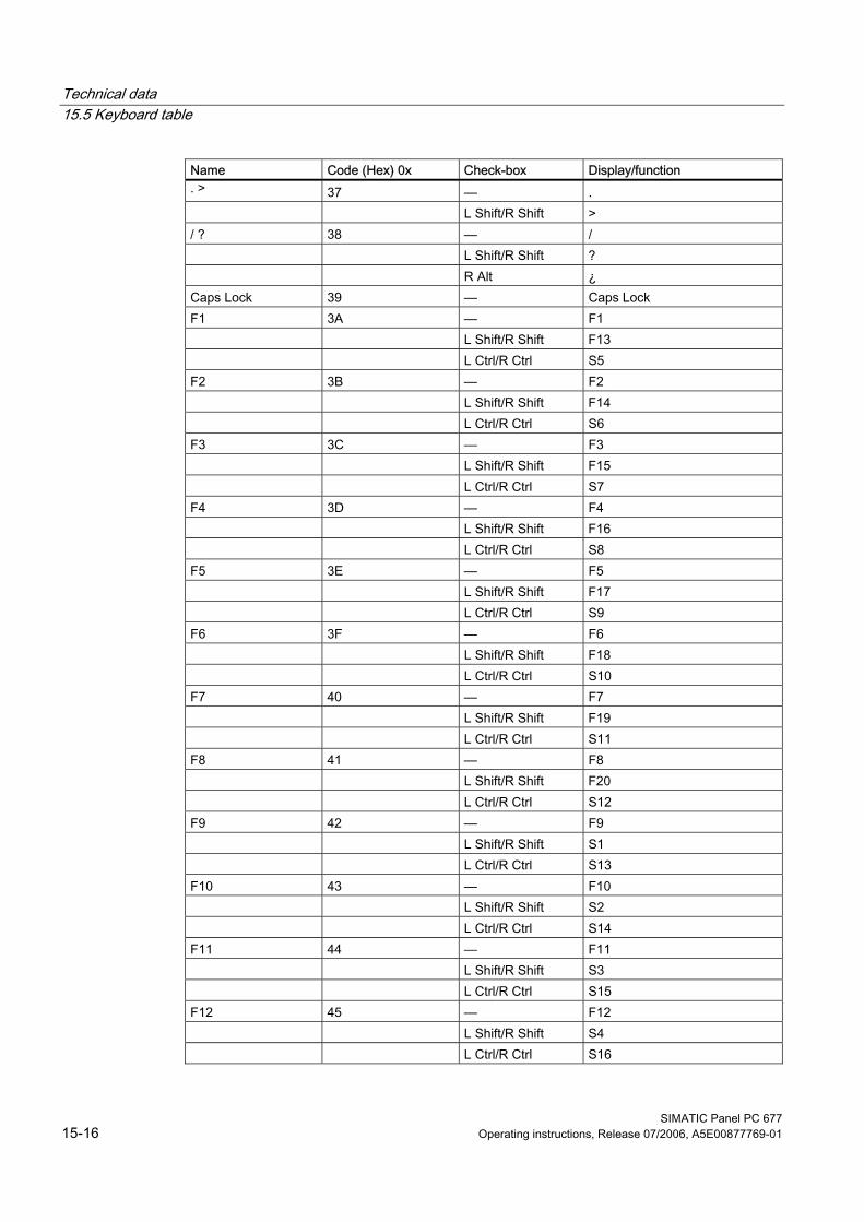
Technical data 15.5 Keyboard table
SIMATIC Panel PC 677 15-16 Operating instructions, Release 07/2006, A5E00877769-01
Name Code (Hex) 0x Check-box Display/function . > 37 — . L Shift/R Shift > / ? 38 — / L Shift/R Shift ? R Alt ¿ Caps Lock 39 — Caps Lock F1 3A — F1 L Shift/R Shift F13 L Ctrl/R Ctrl S5 F2 3B — F2 L Shift/R Shift F14 L Ctrl/R Ctrl S6 F3 3C — F3 L Shift/R Shift F15 L Ctrl/R Ctrl S7 F4 3D — F4 L Shift/R Shift F16 L Ctrl/R Ctrl S8 F5 3E — F5 L Shift/R Shift F17 L Ctrl/R Ctrl S9 F6 3F — F6 L Shift/R Shift F18 L Ctrl/R Ctrl S10 F7 40 — F7 L Shift/R Shift F19 L Ctrl/R Ctrl S11 F8 41 — F8 L Shift/R Shift F20 L Ctrl/R Ctrl S12 F9 42 — F9 L Shift/R Shift S1 L Ctrl/R Ctrl S13 F10 43 — F10 L Shift/R Shift S2 L Ctrl/R Ctrl S14 F11 44 — F11 L Shift/R Shift S3 L Ctrl/R Ctrl S15 F12 45 — F12 L Shift/R Shift S4 L Ctrl/R Ctrl S16

Technical data 15.5 Keyboard table
SIMATIC Panel PC 677 Operating instructions, Release 07/2006, A5E00877769-01 15-17
Name Code (Hex) 0x Check-box Display/function Print Screen, FN+INS 46 — Print Screen, FN+INS Scroll Lock 47 — Scroll Lock Break, Ctrl+Pause 48 — Break, Ctrl+Pause Pause 48 — Pause Insert 49 — Insert Home 4A — Home Page Up 4B — Page Up Delete 4C — Delete End 4D — End Page Down 4E — Page Down Right Arrow 4F — Right Arrow Left Arrow 50 — Left Arrow Down Arrow 51 — Down Arrow Up Arrow 52 — Up Arrow Num Lock 53 — Num Lock Keypad / 54 — Keypad / Keypad * 55 — Keypad * Keypad - 56 — Keypad - Keypad + 57 — Keypad + Keypad Enter 58 — Keypad Enter Keypad 1 End 59 — Keypad 1 End Keypad 2 Down 5A — Keypad 2 Down Keypad 3 PageDn 5B — Keypad 3 PageDn Keypad 4 Left 5C — Keypad 4 Left Keypad 5 5D — Keypad 5 Keypad 6 Right 5E — Keypad 6 Right Keypad 7 Home 5F — Keypad 7 Home Keypad 8 Up 60 — Keypad 8 Up Keypad 9 PageDn 61 — Keypad 9 PageDn Keypad 0 Insert 62 — Keypad 0 Insert Keypad . Delete 63 — Keypad . Delete Europe 2 64 — Europe 2 App 65 — App Keyboard Power 66 — Keyboard Power Keypad = 67 — Keypad =
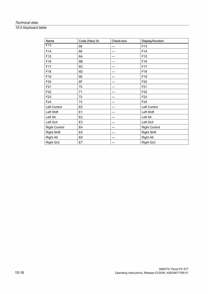
Technical data 15.5 Keyboard table
SIMATIC Panel PC 677 15-18 Operating instructions, Release 07/2006, A5E00877769-01
Name Code (Hex) 0x Check-box Display/function F13 68 — F13 F14 69 — F14 F15 6A — F15 F16 6B — F16 F17 6C — F17 F18 6D — F18 F19 6E — F19 F20 6F — F20 F21 70 — F21 F22 71 — F22 F23 72 — F23 F24 73 — F24 Left Control E0 — Left Control Left Shift E1 — Left Shift Left Alt E2 — Left Alt Left GUI E3 — Left GUI Right Control E4 — Right Control Right Shift E5 — Right Shift Right Alt E6 — Right Alt Right GUI E7 — Right GUI
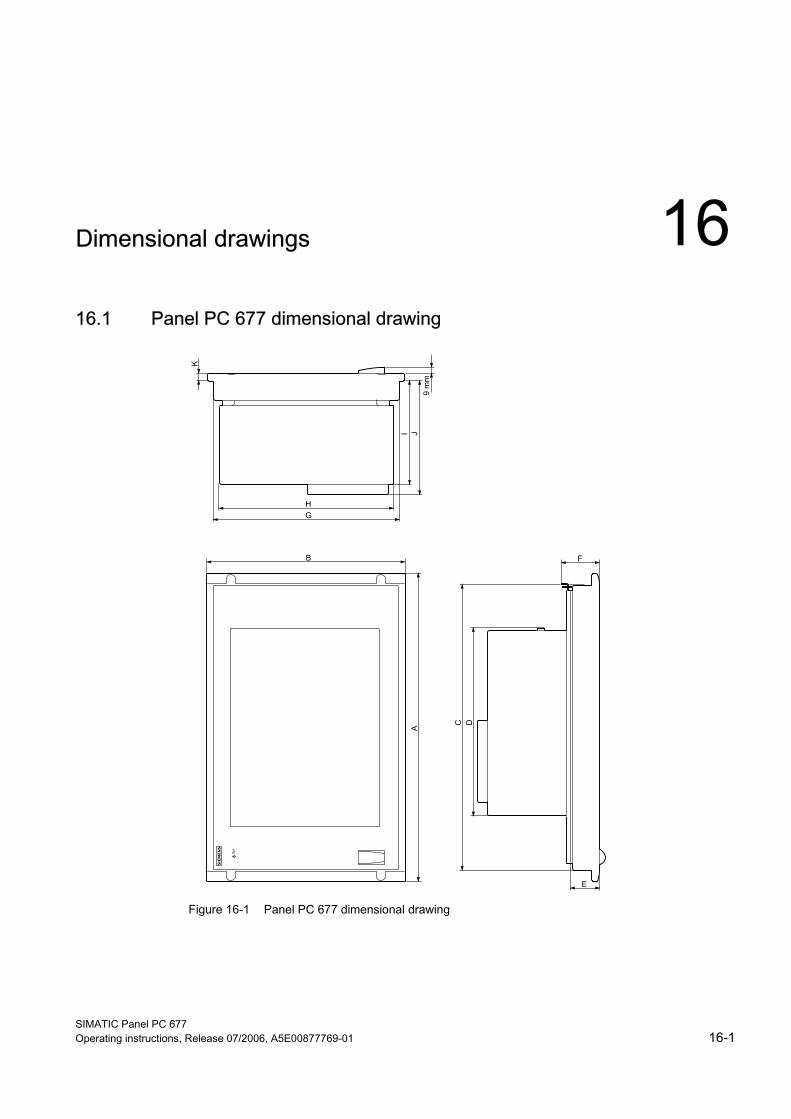
SIMATIC Panel PC 677 Operating instructions, Release 07/2006, A5E00877769-01 16-1
Dimensional drawings 1616.1 16.1 Panel PC 677 dimensional drawing
Figure 16-1 Panel PC 677 dimensional drawing
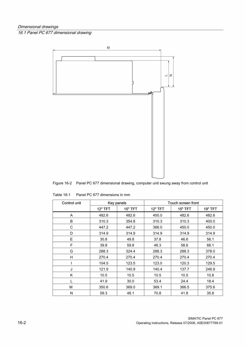
Dimensional drawings 16.1 Panel PC 677 dimensional drawing
SIMATIC Panel PC 677 16-2 Operating instructions, Release 07/2006, A5E00877769-01
Figure 16-2 Panel PC 677 dimensional drawing, computer unit swung away from control unit
Table 16-1 Panel PC 677 dimensions in mm
Key panels Touch screen front Control unit 12" TFT 15" TFT 12" TFT 15" TFT 19" TFT
A 482.6 482.6 400.0 482.6 482.6 B 310.3 354.8 310.3 310.3 400.0 C 447.2 447.2 366.0 450.0 450.0 D 314.9 314.9 314.9 314.9 314.9 E 30.8 49.8 37.8 46.6 56.1 F 39.8 59.8 48.3 58.6 68.1 G 288.3 324.4 288.3 288.3 378.0 H 270.4 270.4 270.4 270.4 270.4 I 104.5 123.5 123.0 120.3 129.5 J 121.9 140.9 140.4 137.7 246.9 K 10.5 10.5 10.5 10.5 10.8 L 41.9 30.0 53.4 24.4 18.4
M 350.6 369.0 369.1 366.5 375.6 N 59.3 48.1 70.8 41.8 35.8

Dimensional drawings 16.2 Panel PC 677 dimensional drawing with stainless steel front
SIMATIC Panel PC 677 Operating instructions, Release 07/2006, A5E00877769-01 16-3
16.2 16.2 Panel PC 677 dimensional drawing with stainless steel front
Figure 16-3 Mounting cut-out
1 Computer unit in final position 2 Computer unit swiveled by 90°
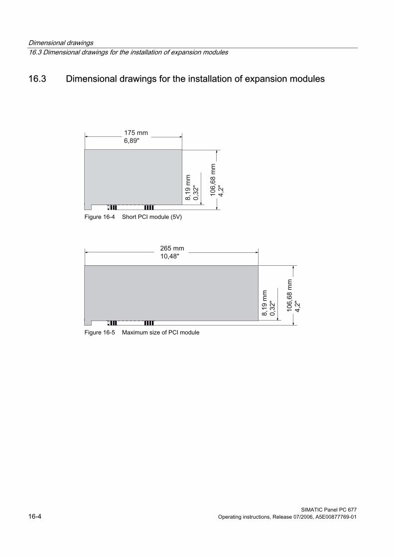
Dimensional drawings 16.3 Dimensional drawings for the installation of expansion modules
SIMATIC Panel PC 677 16-4 Operating instructions, Release 07/2006, A5E00877769-01
16.3 16.3 Dimensional drawings for the installation of expansion modules
Figure 16-4 Short PCI module (5V)
Figure 16-5 Maximum size of PCI module
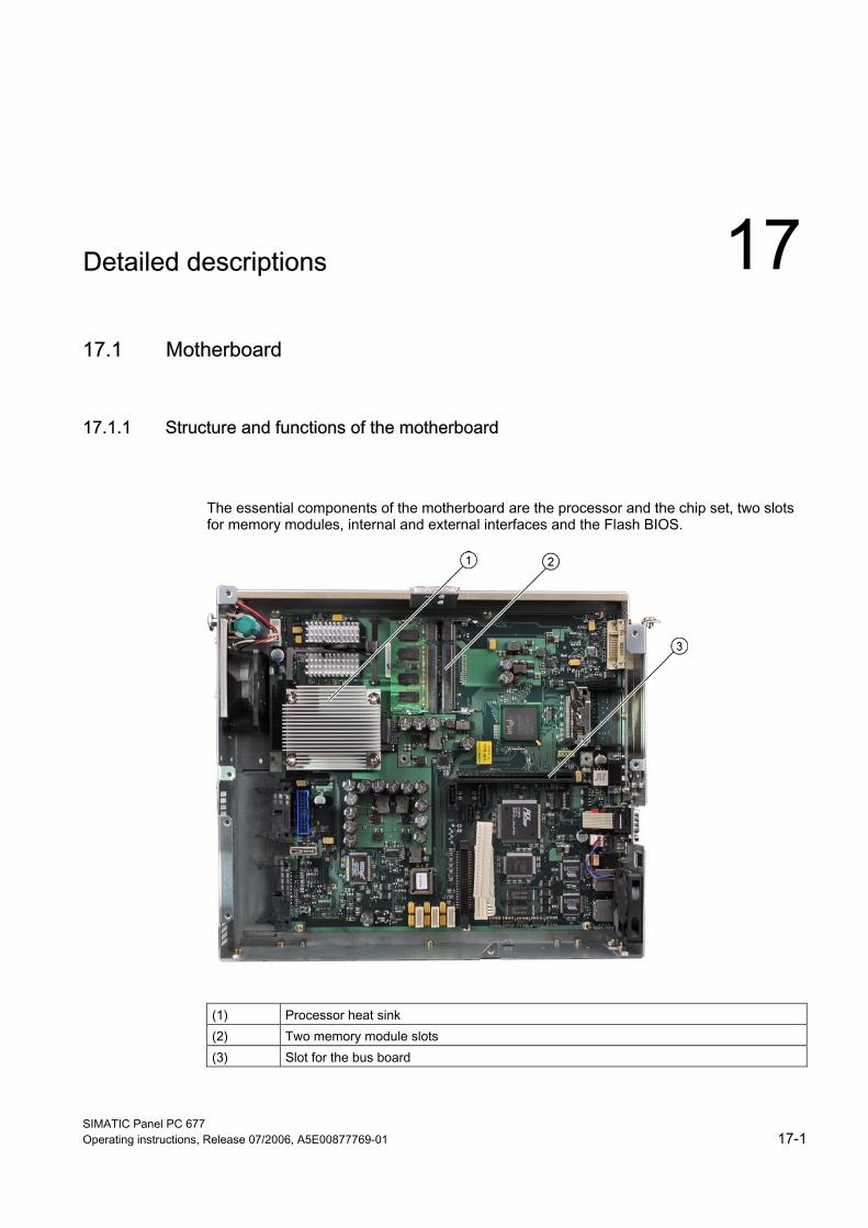
SIMATIC Panel PC 677 Operating instructions, Release 07/2006, A5E00877769-01 17-1
Detailed descriptions 1717.1 17.1 Motherboard
17.1.1 Structure and functions of the motherboard
The essential components of the motherboard are the processor and the chip set, two slots for memory modules, internal and external interfaces and the Flash BIOS.
(1) Processor heat sink (2) Two memory module slots (3) Slot for the bus board
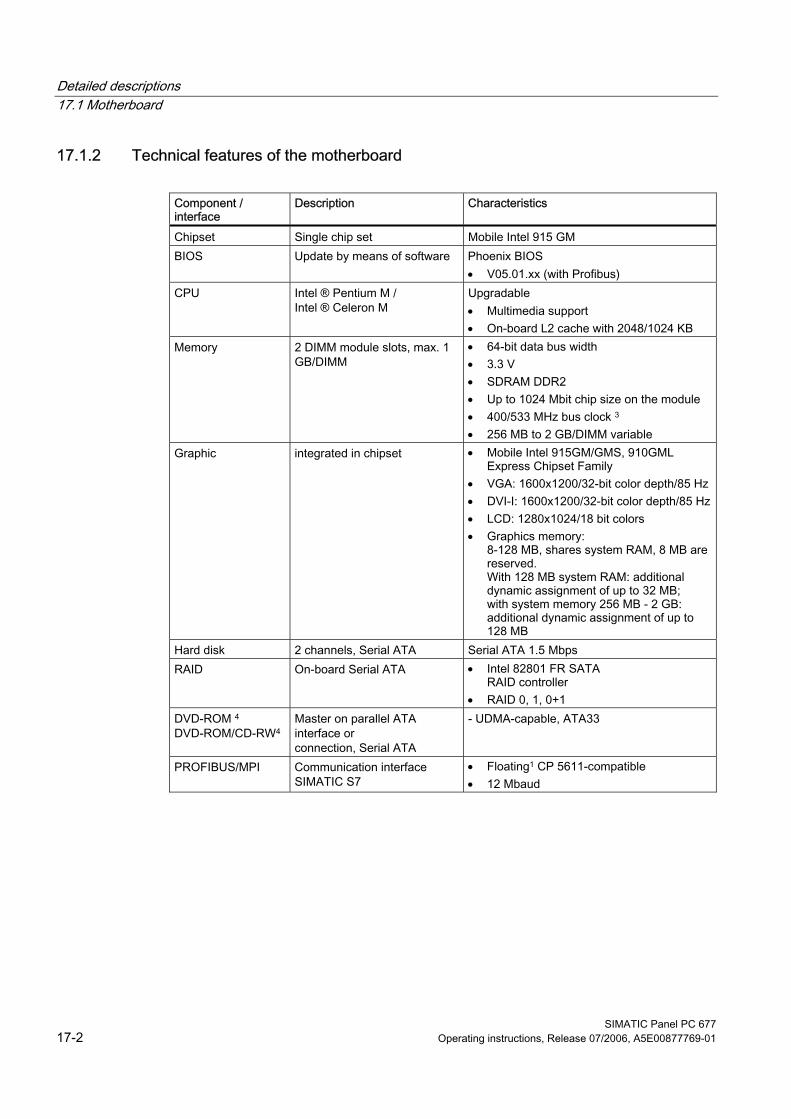
Detailed descriptions 17.1 Motherboard
SIMATIC Panel PC 677 17-2 Operating instructions, Release 07/2006, A5E00877769-01
17.1.2 Technical features of the motherboard
Component / interface
Description Characteristics
Chipset Single chip set Mobile Intel 915 GM BIOS Update by means of software Phoenix BIOS
• V05.01.xx (with Profibus) CPU Intel ® Pentium M /
Intel ® Celeron M Upgradable • Multimedia support • On-board L2 cache with 2048/1024 KB
Memory 2 DIMM module slots, max. 1 GB/DIMM
• 64-bit data bus width • 3.3 V • SDRAM DDR2 • Up to 1024 Mbit chip size on the module • 400/533 MHz bus clock 3 • 256 MB to 2 GB/DIMM variable
Graphic integrated in chipset • Mobile Intel 915GM/GMS, 910GML Express Chipset Family
• VGA: 1600x1200/32-bit color depth/85 Hz • DVI-I: 1600x1200/32-bit color depth/85 Hz• LCD: 1280x1024/18 bit colors • Graphics memory:
8-128 MB, shares system RAM, 8 MB are reserved. With 128 MB system RAM: additional dynamic assignment of up to 32 MB; with system memory 256 MB - 2 GB: additional dynamic assignment of up to 128 MB
Hard disk 2 channels, Serial ATA Serial ATA 1.5 Mbps RAID On-board Serial ATA • Intel 82801 FR SATA
RAID controller • RAID 0, 1, 0+1
DVD-ROM 4
DVD-ROM/CD-RW4 Master on parallel ATA interface or connection, Serial ATA
- UDMA-capable, ATA33
PROFIBUS/MPI Communication interface SIMATIC S7
• Floating1 CP 5611-compatible • 12 Mbaud

Detailed descriptions 17.1 Motherboard
SIMATIC Panel PC 677 Operating instructions, Release 07/2006, A5E00877769-01 17-3
Component / interface
Description Characteristics
USB Universal Serial Bus • External: 4x USB 2.0 on the interface side (max. 2 can be simultaneously operated as high current)
• Internal: 2x USB 2.0 (1x high current, 1x low current)
• Front panel ports: 1x USB 2.0 high current
Ethernet 2x 10BaseT/100Base-TX -10/100 Mbps, isolated1 1 Electrically isolated within the safety extra-low voltage circuit (SELV) 2 Optional product feature 3 Depends on the CPU type 4 Depends on the selected device configuration
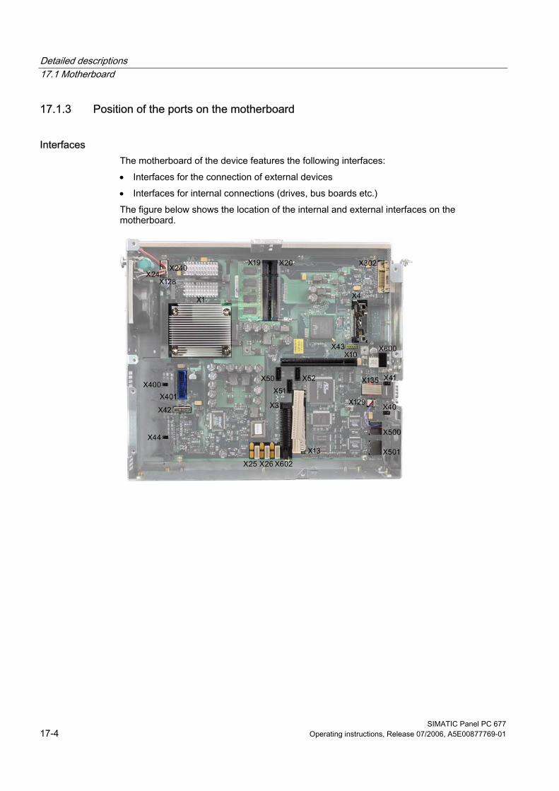
Detailed descriptions 17.1 Motherboard
SIMATIC Panel PC 677 17-4 Operating instructions, Release 07/2006, A5E00877769-01
17.1.3 Position of the ports on the motherboard
Interfaces The motherboard of the device features the following interfaces: • Interfaces for the connection of external devices • Interfaces for internal connections (drives, bus boards etc.) The figure below shows the location of the internal and external interfaces on the motherboard.
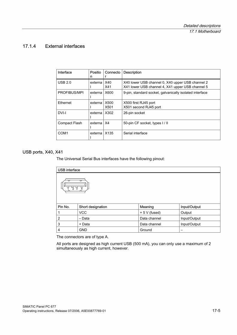
Detailed descriptions 17.1 Motherboard
SIMATIC Panel PC 677 Operating instructions, Release 07/2006, A5E00877769-01 17-5
17.1.4 External interfaces
Interface Position
Connector
Description
USB 2.0 external
X40 X41
X40 lower USB channel 0, X40 upper USB channel 2 X41 lower USB channel 4, X41 upper USB channel 5
PROFIBUS/MPI external
X600 9-pin, standard socket, galvanically isolated interface
Ethernet external
X500 X501
X500 first RJ45 port X501 second RJ45 port
DVI-I external
X302 26-pin socket
Compact Flash external
X4 50-pin CF socket, types I / II
COM1 external
X135 Serial interface
USB ports, X40, X41 The Universal Serial Bus interfaces have the following pinout:
USB interface
Pin No. Short designation Meaning Input/Output 1 VCC + 5 V (fused) Output 2 – Data Data channel Input/Output 3 + Data Data channel Input/Output 4 GND Ground –
The connectors are of type A. All ports are designed as high current USB (500 mA), you can only use a maximum of 2 simultaneously as high current, however.
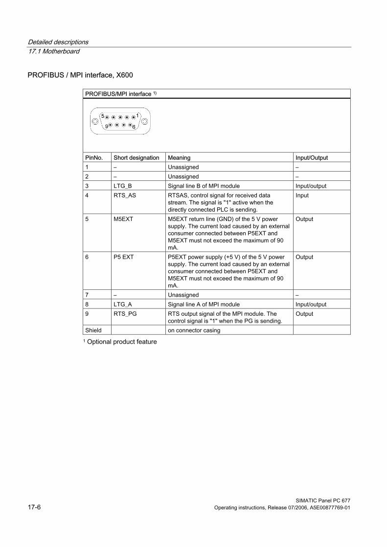
Detailed descriptions 17.1 Motherboard
SIMATIC Panel PC 677 17-6 Operating instructions, Release 07/2006, A5E00877769-01
PROFIBUS / MPI interface, X600
PROFIBUS/MPI interface 1)
PinNo. Short designation Meaning Input/Output 1 – Unassigned – 2 – Unassigned – 3 LTG_B Signal line B of MPI module Input/output 4 RTS_AS RTSAS, control signal for received data
stream. The signal is "1" active when the directly connected PLC is sending.
Input
5 M5EXT M5EXT return line (GND) of the 5 V power supply. The current load caused by an external consumer connected between P5EXT and M5EXT must not exceed the maximum of 90 mA.
Output
6 P5 EXT P5EXT power supply (+5 V) of the 5 V power supply. The current load caused by an external consumer connected between P5EXT and M5EXT must not exceed the maximum of 90 mA.
Output
7 – Unassigned – 8 LTG_A Signal line A of MPI module Input/output 9 RTS_PG RTS output signal of the MPI module. The
control signal is "1" when the PG is sending. Output
Shield on connector casing 1 Optional product feature
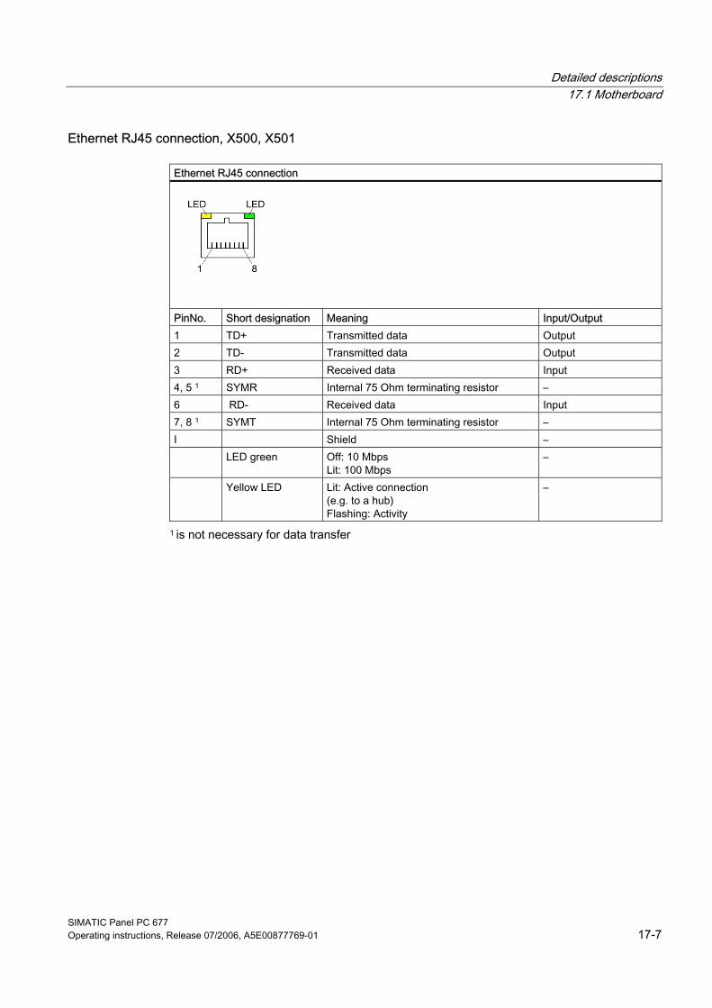
Detailed descriptions 17.1 Motherboard
SIMATIC Panel PC 677 Operating instructions, Release 07/2006, A5E00877769-01 17-7
Ethernet RJ45 connection, X500, X501
Ethernet RJ45 connection
PinNo. Short designation Meaning Input/Output 1 TD+ Transmitted data Output 2 TD- Transmitted data Output 3 RD+ Received data Input 4, 5 1 SYMR Internal 75 Ohm terminating resistor – 6 RD- Received data Input 7, 8 1 SYMT Internal 75 Ohm terminating resistor – I Shield – LED green Off: 10 Mbps
Lit: 100 Mbps –
Yellow LED Lit: Active connection (e.g. to a hub) Flashing: Activity
–
1 is not necessary for data transfer
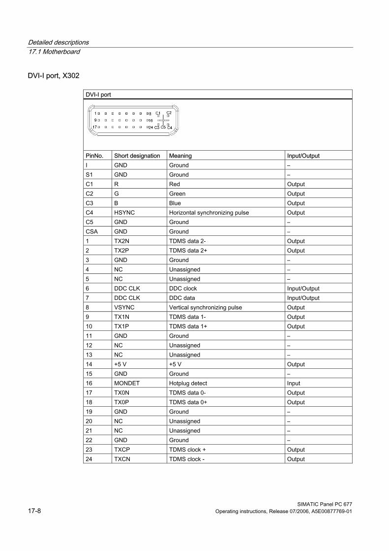
Detailed descriptions 17.1 Motherboard
SIMATIC Panel PC 677 17-8 Operating instructions, Release 07/2006, A5E00877769-01
DVI-I port, X302
DVI-I port
PinNo. Short designation Meaning Input/Output I GND Ground – S1 GND Ground – C1 R Red Output C2 G Green Output C3 B Blue Output C4 HSYNC Horizontal synchronizing pulse Output C5 GND Ground – CSA GND Ground – 1 TX2N TDMS data 2- Output 2 TX2P TDMS data 2+ Output 3 GND Ground – 4 NC Unassigned – 5 NC Unassigned – 6 DDC CLK DDC clock Input/Output 7 DDC CLK DDC data Input/Output 8 VSYNC Vertical synchronizing pulse Output 9 TX1N TDMS data 1- Output 10 TX1P TDMS data 1+ Output 11 GND Ground – 12 NC Unassigned – 13 NC Unassigned – 14 +5 V +5 V Output 15 GND Ground – 16 MONDET Hotplug detect Input 17 TX0N TDMS data 0- Output 18 TX0P TDMS data 0+ Output 19 GND Ground – 20 NC Unassigned – 21 NC Unassigned – 22 GND Ground – 23 TXCP TDMS clock + Output 24 TXCN TDMS clock - Output
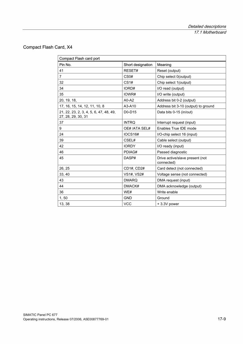
Detailed descriptions 17.1 Motherboard
SIMATIC Panel PC 677 Operating instructions, Release 07/2006, A5E00877769-01 17-9
Compact Flash Card, X4
Compact Flash card port Pin No. Short designation Meaning 41 RESET# Reset (output) 7 CS0# Chip select 0(output) 32 CS1# Chip select 1(output) 34 IORD# I/O read (output) 35 IOWR# I/O write (output) 20, 19, 18, A0-A2 Address bit 0-2 (output) 17, 16, 15, 14, 12, 11, 10, 8 A3-A10 Address bit 3-10 (output) to ground 21, 22, 23, 2, 3, 4, 5, 6, 47, 48, 49, 27, 28, 29, 30, 31
D0-D15 Data bits 0-15 (in/out)
37 INTRQ Interrupt request (input) 9 OE# /ATA SEL# Enables True IDE mode 24 IOCS16# I/O-chip select 16 (input) 39 CSEL# Cable select (output) 42 IORDY I/O ready (input) 46 PDIAG# Passed diagnostic 45 DASP# Drive active/slave present (not
connected) 26, 25 CD1#, CD2# Card detect (not connected) 33, 40 VS1#, VS2# Voltage sense (not connected) 43 DMARQ DMA request (input) 44 DMACK# DMA acknowledge (output) 36 WE# Write enable 1, 50 GND Ground 13, 38 VCC + 3.3V power
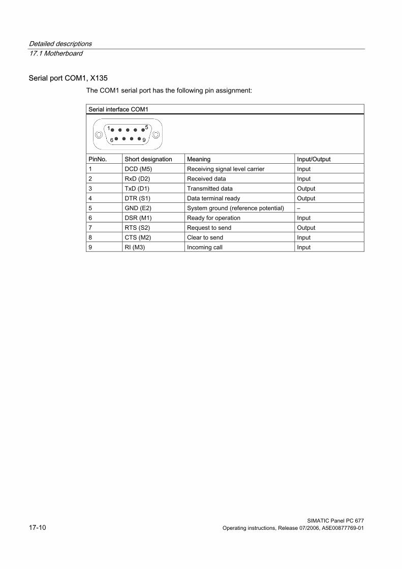
Detailed descriptions 17.1 Motherboard
SIMATIC Panel PC 677 17-10 Operating instructions, Release 07/2006, A5E00877769-01
Serial port COM1, X135 The COM1 serial port has the following pin assignment:
Serial interface COM1
PinNo. Short designation Meaning Input/Output 1 DCD (M5) Receiving signal level carrier Input 2 RxD (D2) Received data Input 3 TxD (D1) Transmitted data Output 4 DTR (S1) Data terminal ready Output 5 GND (E2) System ground (reference potential) – 6 DSR (M1) Ready for operation Input 7 RTS (S2) Request to send Output 8 CTS (M2) Clear to send Input 9 RI (M3) Incoming call Input
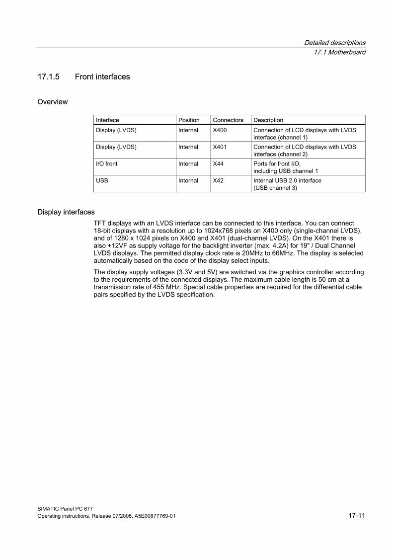
Detailed descriptions 17.1 Motherboard
SIMATIC Panel PC 677 Operating instructions, Release 07/2006, A5E00877769-01 17-11
17.1.5 Front interfaces
Overview
Interface Position Connectors Description Display (LVDS) Internal X400 Connection of LCD displays with LVDS
interface (channel 1) Display (LVDS) Internal X401 Connection of LCD displays with LVDS
interface (channel 2) I/O front Internal X44 Ports for front I/O,
including USB channel 1 USB Internal X42 Internal USB 2.0 interface
(USB channel 3)
Display interfaces TFT displays with an LVDS interface can be connected to this interface. You can connect 18-bit displays with a resolution up to 1024x768 pixels on X400 only (single-channel LVDS), and of 1280 x 1024 pixels on X400 and X401 (dual-channel LVDS). On the X401 there is also +12VF as supply voltage for the backlight inverter (max. 4.2A) for 19" / Dual Channel LVDS displays. The permitted display clock rate is 20MHz to 66MHz. The display is selected automatically based on the code of the display select inputs. The display supply voltages (3.3V and 5V) are switched via the graphics controller according to the requirements of the connected displays. The maximum cable length is 50 cm at a transmission rate of 455 MHz. Special cable properties are required for the differential cable pairs specified by the LVDS specification.
Detailed descriptions 17.1 Motherboard
SIMATIC Panel PC 677 17-12 Operating instructions, Release 07/2006, A5E00877769-01
Display interface (1st LVDS channel), X400 Pin No. Short designation Meaning Input/Output 1 P5V_D_fused +5V (fused) display VCC Output 2 P5V_D_fused +5V (fused) display VCC Output 3 RXIN0- LVDS output signal bit 0 (-) Output 4 RXIN0+ LVDS output signal bit 0 (+) Output 5 P3V3_D_fused +3.3V (fused) display VCC Output 6 P3V3_D_fused +3.3V (fused) display VCC Output 7 RXIN1- LVDS output signal bit 1 (-) Output 8 RXIN1+ LVDS output signal bit 1 (+) Output 9 GND Ground - 10 GND Ground - 11 RXIN2- LVDS output signal bit 2 (-) Output 12 RXIN2+ LVDS output signal bit 2 (+) Output 13 GND Ground - 14 GND Ground - 15 RXCLKIN- LVDS clock signal (-) Output 16 RXCLKIN+ LVDS clock signal (+) Output 17 GND Ground - 18 GND Ground - 19 NC Unassigned - 20 NC Unassigned -
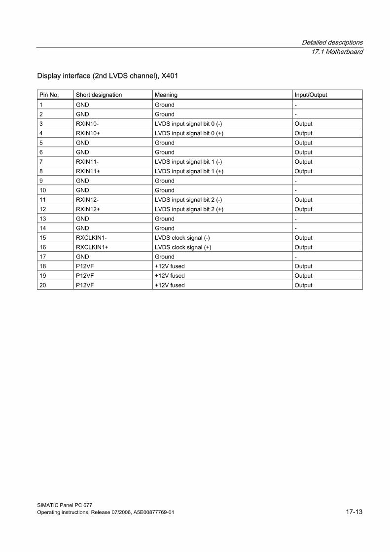
Detailed descriptions 17.1 Motherboard
SIMATIC Panel PC 677 Operating instructions, Release 07/2006, A5E00877769-01 17-13
Display interface (2nd LVDS channel), X401 Pin No. Short designation Meaning Input/Output 1 GND Ground - 2 GND Ground - 3 RXIN10- LVDS input signal bit 0 (-) Output 4 RXIN10+ LVDS input signal bit 0 (+) Output 5 GND Ground Output 6 GND Ground Output 7 RXIN11- LVDS input signal bit 1 (-) Output 8 RXIN11+ LVDS input signal bit 1 (+) Output 9 GND Ground - 10 GND Ground - 11 RXIN12- LVDS input signal bit 2 (-) Output 12 RXIN12+ LVDS input signal bit 2 (+) Output 13 GND Ground - 14 GND Ground - 15 RXCLKIN1- LVDS clock signal (-) Output 16 RXCLKIN1+ LVDS clock signal (+) Output 17 GND Ground - 18 P12VF +12V fused Output 19 P12VF +12V fused Output 20 P12VF +12V fused Output
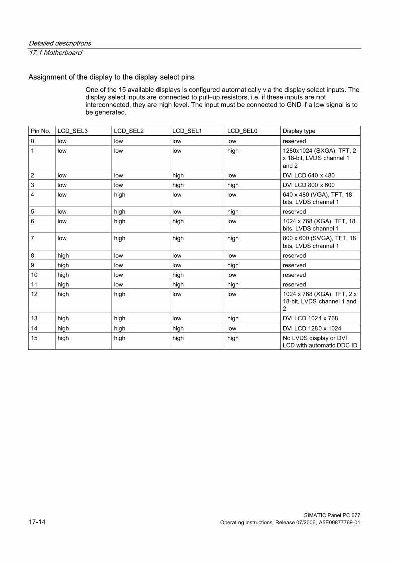
Detailed descriptions 17.1 Motherboard
SIMATIC Panel PC 677 17-14 Operating instructions, Release 07/2006, A5E00877769-01
Assignment of the display to the display select pins One of the 15 available displays is configured automatically via the display select inputs. The display select inputs are connected to pull–up resistors, i.e. if these inputs are not interconnected, they are high level. The input must be connected to GND if a low signal is to be generated.
Pin No. LCD_SEL3 LCD_SEL2 LCD_SEL1 LCD_SEL0 Display type 0 low low low low reserved 1 low low low high 1280x1024 (SXGA), TFT, 2
x 18-bit, LVDS channel 1 and 2
2 low low high low DVI LCD 640 x 480 3 low low high high DVI LCD 800 x 600 4 low high low low 640 x 480 (VGA), TFT, 18
bits, LVDS channel 1 5 low high low high reserved 6 low high high low 1024 x 768 (XGA), TFT, 18
bits, LVDS channel 1 7 low high high high 800 x 600 (SVGA), TFT, 18
bits, LVDS channel 1 8 high low low low reserved 9 high low low high reserved 10 high low high low reserved 11 high low high high reserved 12 high high low low 1024 x 768 (XGA), TFT, 2 x
18-bit, LVDS channel 1 and 2
13 high high low high DVI LCD 1024 x 768 14 high high high low DVI LCD 1280 x 1024 15 high high high high No LVDS display or DVI
LCD with automatic DDC ID
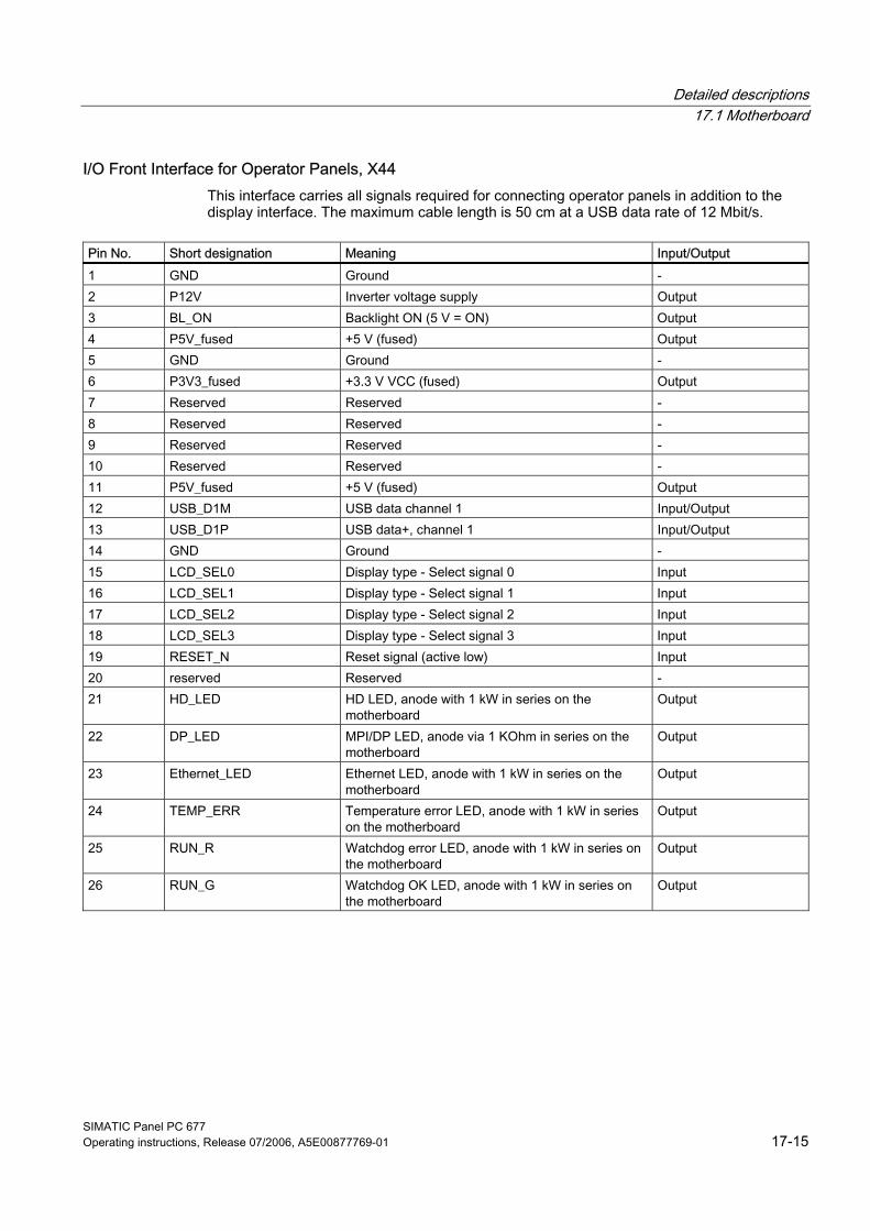
Detailed descriptions 17.1 Motherboard
SIMATIC Panel PC 677 Operating instructions, Release 07/2006, A5E00877769-01 17-15
I/O Front Interface for Operator Panels, X44 This interface carries all signals required for connecting operator panels in addition to the display interface. The maximum cable length is 50 cm at a USB data rate of 12 Mbit/s.
Pin No. Short designation Meaning Input/Output 1 GND Ground - 2 P12V Inverter voltage supply Output 3 BL_ON Backlight ON (5 V = ON) Output 4 P5V_fused +5 V (fused) Output 5 GND Ground - 6 P3V3_fused +3.3 V VCC (fused) Output 7 Reserved Reserved - 8 Reserved Reserved - 9 Reserved Reserved - 10 Reserved Reserved - 11 P5V_fused +5 V (fused) Output 12 USB_D1M USB data channel 1 Input/Output 13 USB_D1P USB data+, channel 1 Input/Output 14 GND Ground - 15 LCD_SEL0 Display type - Select signal 0 Input 16 LCD_SEL1 Display type - Select signal 1 Input 17 LCD_SEL2 Display type - Select signal 2 Input 18 LCD_SEL3 Display type - Select signal 3 Input 19 RESET_N Reset signal (active low) Input 20 reserved Reserved - 21 HD_LED HD LED, anode with 1 kW in series on the
motherboard Output
22 DP_LED MPI/DP LED, anode via 1 KOhm in series on the motherboard
Output
23 Ethernet_LED Ethernet LED, anode with 1 kW in series on the motherboard
Output
24 TEMP_ERR Temperature error LED, anode with 1 kW in series on the motherboard
Output
25 RUN_R Watchdog error LED, anode with 1 kW in series on the motherboard
Output
26 RUN_G Watchdog OK LED, anode with 1 kW in series on the motherboard
Output
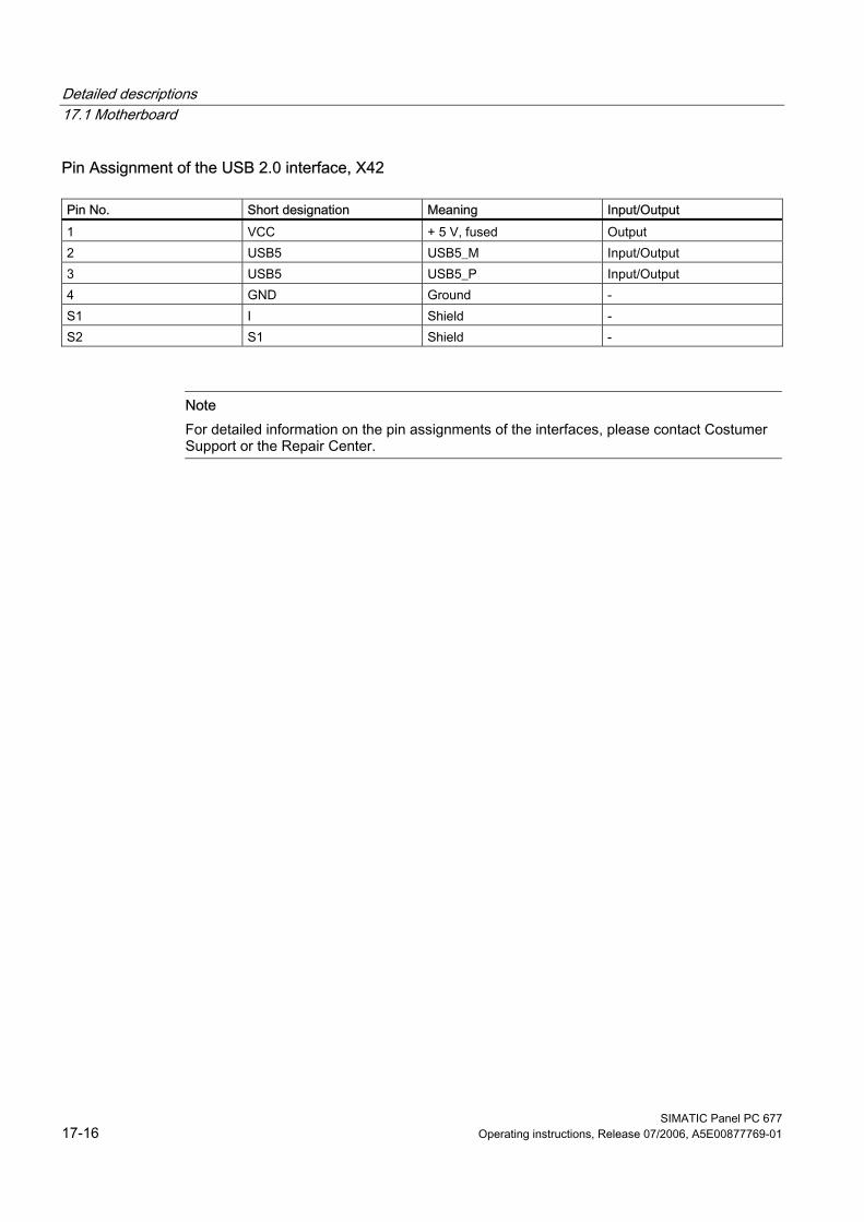
Detailed descriptions 17.1 Motherboard
SIMATIC Panel PC 677 17-16 Operating instructions, Release 07/2006, A5E00877769-01
Pin Assignment of the USB 2.0 interface, X42 Pin No. Short designation Meaning Input/Output 1 VCC + 5 V, fused Output 2 USB5 USB5_M Input/Output 3 USB5 USB5_P Input/Output 4 GND Ground - S1 I Shield - S2 S1 Shield -
Note For detailed information on the pin assignments of the interfaces, please contact Costumer Support or the Repair Center.
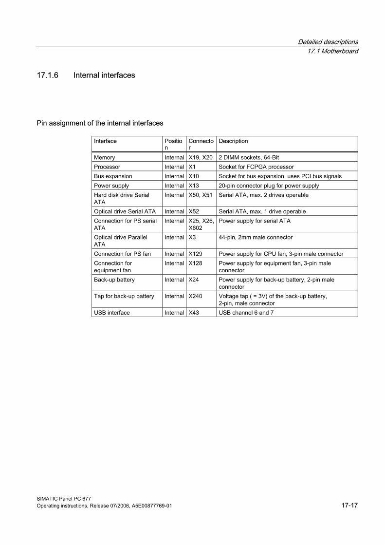
Detailed descriptions 17.1 Motherboard
SIMATIC Panel PC 677 Operating instructions, Release 07/2006, A5E00877769-01 17-17
17.1.6 Internal interfaces
Pin assignment of the internal interfaces
Interface Position
Connector
Description
Memory Internal X19, X20 2 DIMM sockets, 64-Bit Processor Internal X1 Socket for FCPGA processor Bus expansion Internal X10 Socket for bus expansion, uses PCI bus signals Power supply Internal X13 20-pin connector plug for power supply Hard disk drive Serial ATA
Internal X50, X51 Serial ATA, max. 2 drives operable
Optical drive Serial ATA Internal X52 Serial ATA, max. 1 drive operable Connection for PS serial ATA
Internal X25, X26, X602
Power supply for serial ATA
Optical drive Parallel ATA
Internal X3 44-pin, 2mm male connector
Connection for PS fan Internal X129 Power supply for CPU fan, 3-pin male connector Connection for equipment fan
Internal X128 Power supply for equipment fan, 3-pin male connector
Back-up battery Internal X24 Power supply for back-up battery, 2-pin male connector
Tap for back-up battery Internal X240 Voltage tap ( = 3V) of the back-up battery, 2-pin, male connector
USB interface Internal X43 USB channel 6 and 7
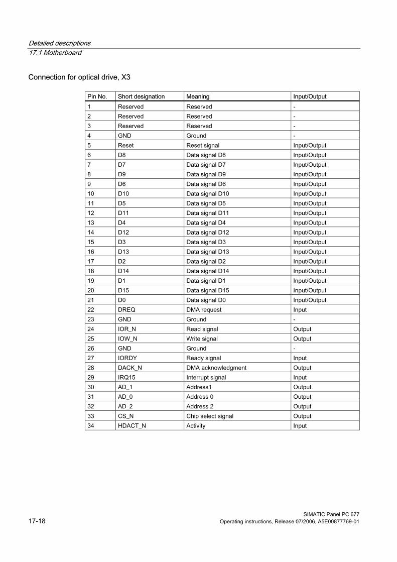
Detailed descriptions 17.1 Motherboard
SIMATIC Panel PC 677 17-18 Operating instructions, Release 07/2006, A5E00877769-01
Connection for optical drive, X3
Pin No. Short designation Meaning Input/Output 1 Reserved Reserved - 2 Reserved Reserved - 3 Reserved Reserved - 4 GND Ground - 5 Reset Reset signal Input/Output 6 D8 Data signal D8 Input/Output 7 D7 Data signal D7 Input/Output 8 D9 Data signal D9 Input/Output 9 D6 Data signal D6 Input/Output 10 D10 Data signal D10 Input/Output 11 D5 Data signal D5 Input/Output 12 D11 Data signal D11 Input/Output 13 D4 Data signal D4 Input/Output 14 D12 Data signal D12 Input/Output 15 D3 Data signal D3 Input/Output 16 D13 Data signal D13 Input/Output 17 D2 Data signal D2 Input/Output 18 D14 Data signal D14 Input/Output 19 D1 Data signal D1 Input/Output 20 D15 Data signal D15 Input/Output 21 D0 Data signal D0 Input/Output 22 DREQ DMA request Input 23 GND Ground - 24 IOR_N Read signal Output 25 IOW_N Write signal Output 26 GND Ground - 27 IORDY Ready signal Input 28 DACK_N DMA acknowledgment Output 29 IRQ15 Interrupt signal Input 30 AD_1 Address1 Output 31 AD_0 Address 0 Output 32 AD_2 Address 2 Output 33 CS_N Chip select signal Output 34 HDACT_N Activity Input
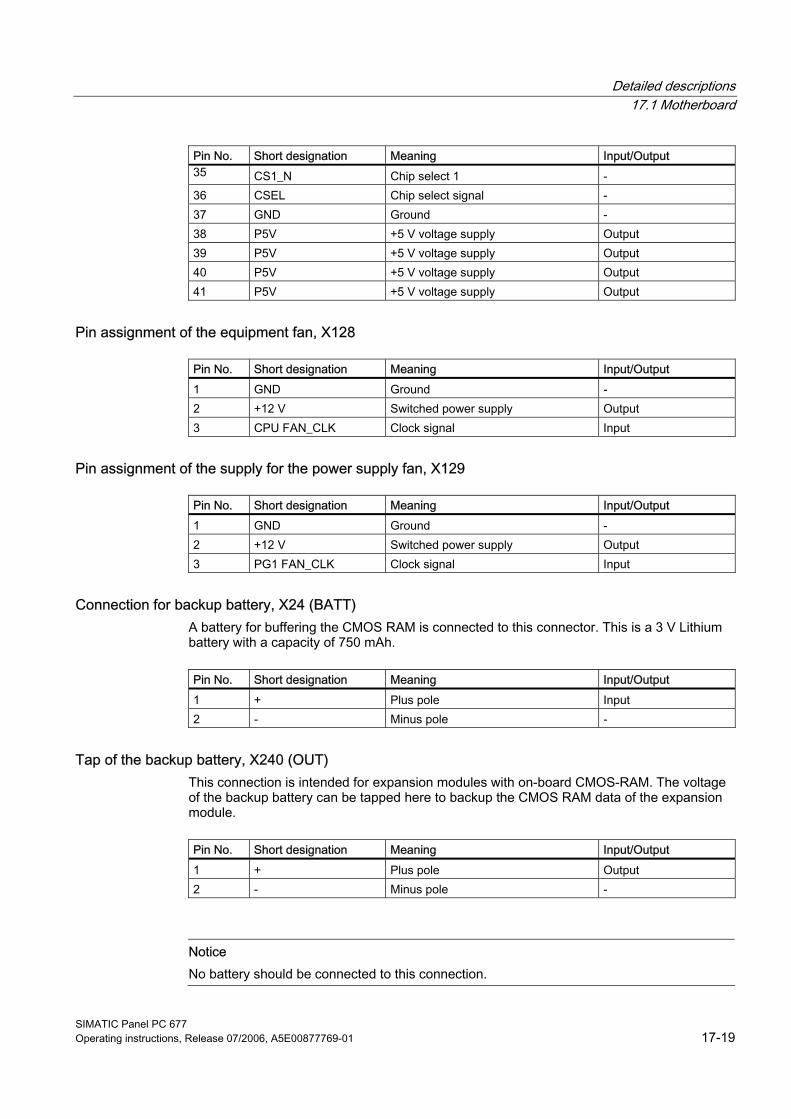
Detailed descriptions 17.1 Motherboard
SIMATIC Panel PC 677 Operating instructions, Release 07/2006, A5E00877769-01 17-19
Pin No. Short designation Meaning Input/Output 35 CS1_N Chip select 1 - 36 CSEL Chip select signal - 37 GND Ground - 38 P5V +5 V voltage supply Output 39 P5V +5 V voltage supply Output 40 P5V +5 V voltage supply Output 41 P5V +5 V voltage supply Output
Pin assignment of the equipment fan, X128
Pin No. Short designation Meaning Input/Output 1 GND Ground - 2 +12 V Switched power supply Output 3 CPU FAN_CLK Clock signal Input
Pin assignment of the supply for the power supply fan, X129
Pin No. Short designation Meaning Input/Output 1 GND Ground - 2 +12 V Switched power supply Output 3 PG1 FAN_CLK Clock signal Input
Connection for backup battery, X24 (BATT) A battery for buffering the CMOS RAM is connected to this connector. This is a 3 V Lithium battery with a capacity of 750 mAh.
Pin No. Short designation Meaning Input/Output 1 + Plus pole Input 2 - Minus pole -
Tap of the backup battery, X240 (OUT) This connection is intended for expansion modules with on-board CMOS-RAM. The voltage of the backup battery can be tapped here to backup the CMOS RAM data of the expansion module.
Pin No. Short designation Meaning Input/Output 1 + Plus pole Output 2 - Minus pole -
Notice No battery should be connected to this connection.
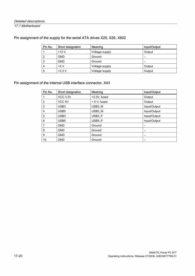
Detailed descriptions 17.1 Motherboard
SIMATIC Panel PC 677 17-20 Operating instructions, Release 07/2006, A5E00877769-01
Pin assignment of the supply for the serial ATA drives X25, X26, X602
Pin No. Short designation Meaning Input/Output 1 +12 V Voltage supply Output 2 GND Ground – 3 GND Ground – 4 +5 V Voltage supply Output 5 +3.3 V Voltage supply Output
Pin assignment of the internal USB interface connector, X43
Pin No. Short designation Meaning Input/Output 1 VCC 3.3V +3.3V, fused Output 2 VCC 5V + 5 V, fused Output 3 USB3 USB3_M Input/Output 4 USB5 USB5_M Input/Output 5 USB3 USB3_P Input/Output 6 USB5 USB5_P Input/Output 7 GND Ground – 8 GND Ground – 9 GND Ground – 10 GND Ground –
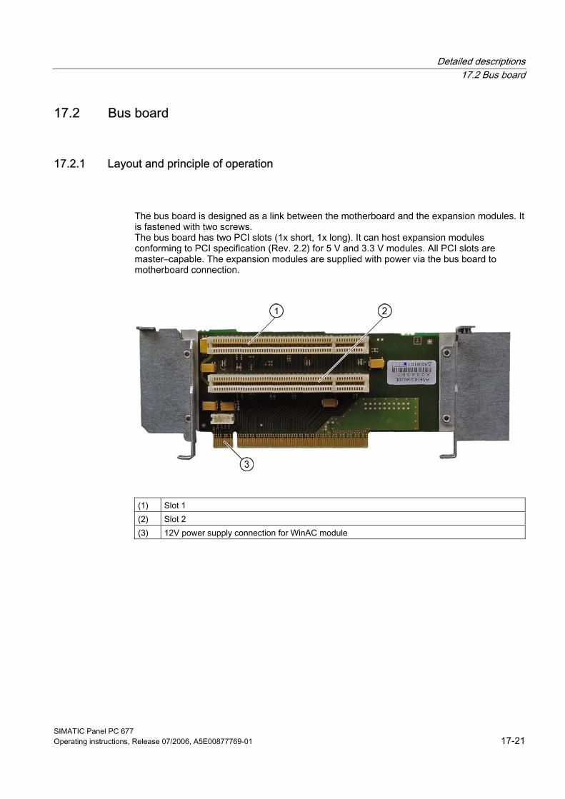
Detailed descriptions 17.2 Bus board
SIMATIC Panel PC 677 Operating instructions, Release 07/2006, A5E00877769-01 17-21
17.2 17.2 Bus board
17.2.1 Layout and principle of operation
The bus board is designed as a link between the motherboard and the expansion modules. It is fastened with two screws. The bus board has two PCI slots (1x short, 1x long). It can host expansion modules conforming to PCI specification (Rev. 2.2) for 5 V and 3.3 V modules. All PCI slots are master–capable. The expansion modules are supplied with power via the bus board to motherboard connection.
(1) Slot 1 (2) Slot 2 (3) 12V power supply connection for WinAC module
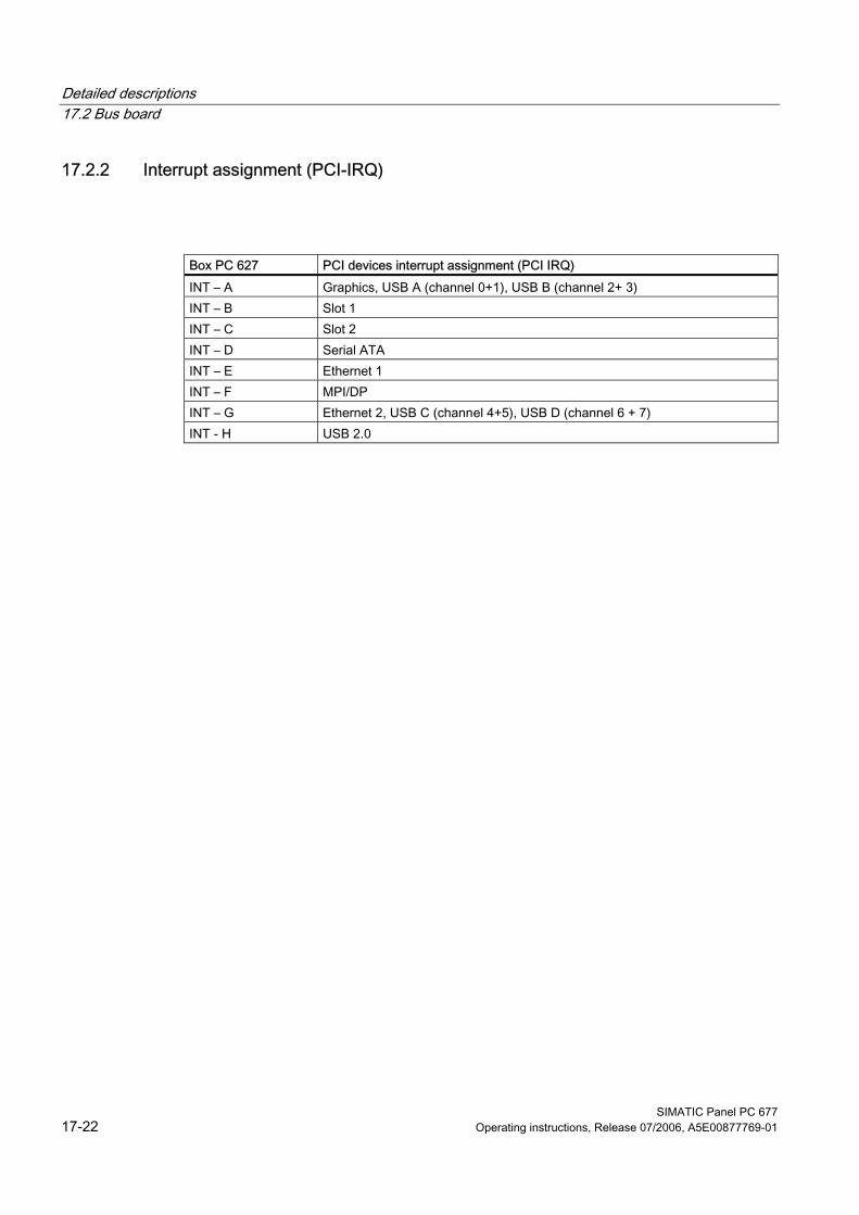
Detailed descriptions 17.2 Bus board
SIMATIC Panel PC 677 17-22 Operating instructions, Release 07/2006, A5E00877769-01
17.2.2 Interrupt assignment (PCI-IRQ)
Box PC 627 PCI devices interrupt assignment (PCI IRQ) INT – A Graphics, USB A (channel 0+1), USB B (channel 2+ 3) INT – B Slot 1 INT – C Slot 2 INT – D Serial ATA INT – E Ethernet 1 INT – F MPI/DP INT – G Ethernet 2, USB C (channel 4+5), USB D (channel 6 + 7) INT - H USB 2.0
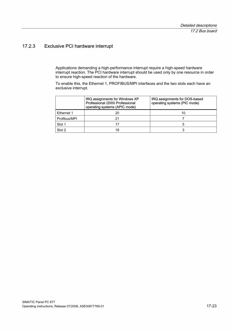
Detailed descriptions 17.2 Bus board
SIMATIC Panel PC 677 Operating instructions, Release 07/2006, A5E00877769-01 17-23
17.2.3 Exclusive PCI hardware interrupt
Applications demanding a high-performance interrupt require a high-speed hardware interrupt reaction. The PCI hardware interrupt should be used only by one resource in order to ensure high-speed reaction of the hardware. To enable this, the Ethernet 1, PROFIBUS/MPI interfaces and the two slots each have an exclusive interrupt.
IRQ assignments for Windows XP
Professional /2000 Professional operating systems (APIC mode)
IRQ assignments for DOS-based operating systems (PIC mode)
Ethernet 1 20 10 Profibus/MPI 21 7 Slot 1 17 5 Slot 2 18 3
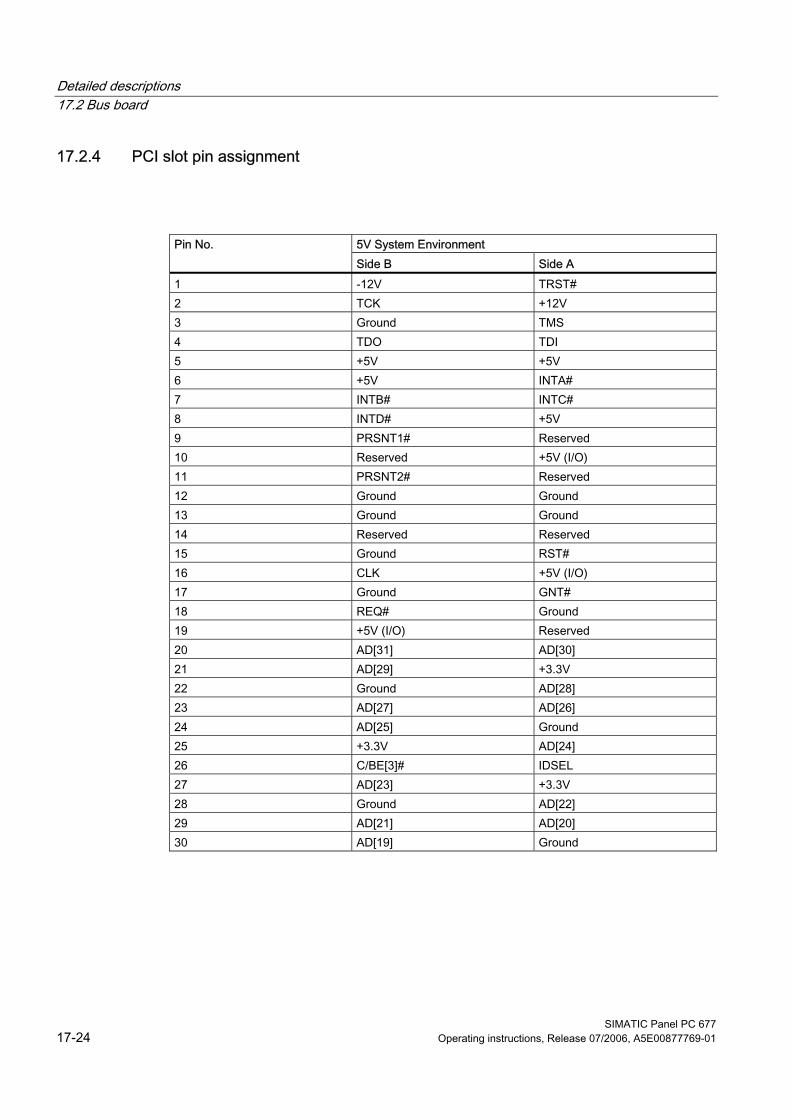
Detailed descriptions 17.2 Bus board
SIMATIC Panel PC 677 17-24 Operating instructions, Release 07/2006, A5E00877769-01
17.2.4 PCI slot pin assignment
5V System Environment Pin No. Side B Side A
1 -12V TRST# 2 TCK +12V 3 Ground TMS 4 TDO TDI 5 +5V +5V 6 +5V INTA# 7 INTB# INTC# 8 INTD# +5V 9 PRSNT1# Reserved 10 Reserved +5V (I/O) 11 PRSNT2# Reserved 12 Ground Ground 13 Ground Ground 14 Reserved Reserved 15 Ground RST# 16 CLK +5V (I/O) 17 Ground GNT# 18 REQ# Ground 19 +5V (I/O) Reserved 20 AD[31] AD[30] 21 AD[29] +3.3V 22 Ground AD[28] 23 AD[27] AD[26] 24 AD[25] Ground 25 +3.3V AD[24] 26 C/BE[3]# IDSEL 27 AD[23] +3.3V 28 Ground AD[22] 29 AD[21] AD[20] 30 AD[19] Ground

Detailed descriptions 17.2 Bus board
SIMATIC Panel PC 677 Operating instructions, Release 07/2006, A5E00877769-01 17-25
5V System Environment 31 +3.3V AD[18]
32 AD[17] AD[16] 33 C/BE[2]# +3.3V 34 Ground FRAME# 35 IRDY# Ground 36 +3.3V TRDY# 37 DEVSEL# Ground 38 Ground STOP# 39 LOCK# +3.3V 40 PERR# SDONE 41 +3.3V SBO# 42 SERR# Ground 43 +3.3V PAR 44 C/BE[1]# AD[15] 45 AD[14] +3.3V 46 Ground AD[13] 47 AD[12] AD[11] 48 AD[10] Ground 49 Ground AD[09] 50 CONNECTOR KEY 51 CONNECTOR KEY 52 AD[08] C/BE[0]# 53 AD[07] +3.3V 54 +3.3V AD[06] 55 AD[05] AD[04] 56 AD[03] Ground 57 Ground AD[02] 58 AD[01] AD[00] 59 +5V (I/O) +5V (I/O) 60 ACK64# REQ64# 61 +5V +5V 62 +5V +5V
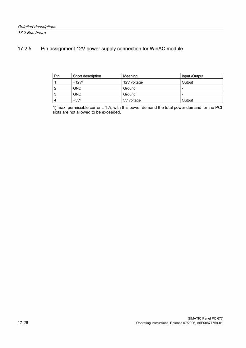
Detailed descriptions 17.2 Bus board
SIMATIC Panel PC 677 17-26 Operating instructions, Release 07/2006, A5E00877769-01
17.2.5 Pin assignment 12V power supply connection for WinAC module
Pin Short description Meaning Input /Output 1 +12V1 12V voltage Output 2 GND Ground - 3 GND Ground - 4 +5V1 5V voltage Output
1) max. permissible current: 1 A; with this power demand the total power demand for the PCI slots are not allowed to be exceeded.
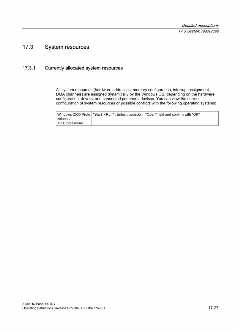
Detailed descriptions 17.3 System resources
SIMATIC Panel PC 677 Operating instructions, Release 07/2006, A5E00877769-01 17-27
17.3 17.3 System resources
17.3.1 Currently allocated system resources
All system resources (hardware addresses, memory configuration, interrupt assignment, DMA channels) are assigned dynamically by the Windows OS, depending on the hardware configuration, drivers, and connected peripheral devices. You can view the current configuration of system resources or possible conflicts with the following operating systems:
Windows 2000 Professional / XP Professional
"Start > Run" : Enter msinfo32 in "Open" field and confirm with "OK"
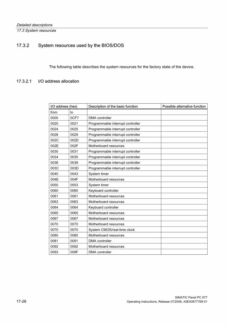
Detailed descriptions 17.3 System resources
SIMATIC Panel PC 677 17-28 Operating instructions, Release 07/2006, A5E00877769-01
17.3.2 System resources used by the BIOS/DOS
The following table describes the system resources for the factory state of the device.
17.3.2.1 I/O address allocation
I/O address (hex) Description of the basic function Possible alternative functionfrom to 0000 0CF7 DMA controller 0020 0021 Programmable interrupt controller 0024 0025 Programmable interrupt controller 0028 0029 Programmable interrupt controller 002C 002D Programmable interrupt controller 002E 002F Motherboard resources 0030 0031 Programmable interrupt controller 0034 0035 Programmable interrupt controller 0038 0039 Programmable interrupt controller 003C 003D Programmable interrupt controller 0040 0043 System timer 004E 004F Motherboard resources 0050 0053 System timer 0060 0060 Keyboard controller 0061 0061 Motherboard resources 0063 0063 Motherboard resources 0064 0064 Keyboard controller 0065 0065 Motherboard resources 0067 0067 Motherboard resources 0070 0070 Motherboard resources 0070 0070 System CMOS/real-time clock 0080 0080 Motherboard resources 0081 0091 DMA controller 0092 0092 Motherboard resources 0093 009F DMA controller
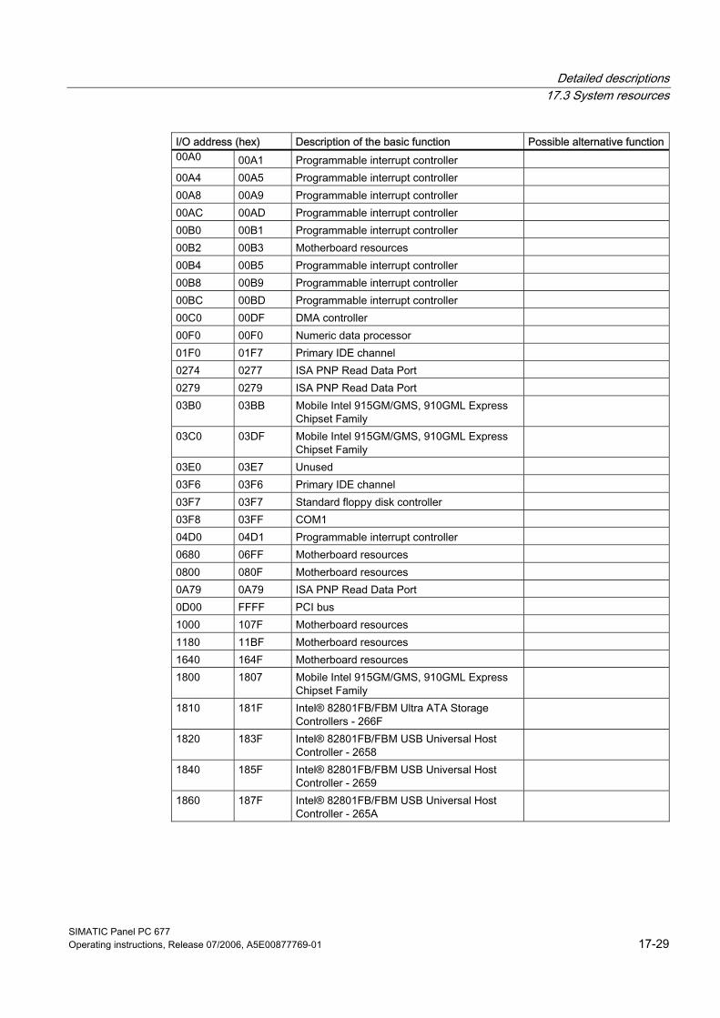
Detailed descriptions 17.3 System resources
SIMATIC Panel PC 677 Operating instructions, Release 07/2006, A5E00877769-01 17-29
I/O address (hex) Description of the basic function Possible alternative function00A0 00A1 Programmable interrupt controller 00A4 00A5 Programmable interrupt controller 00A8 00A9 Programmable interrupt controller 00AC 00AD Programmable interrupt controller 00B0 00B1 Programmable interrupt controller 00B2 00B3 Motherboard resources 00B4 00B5 Programmable interrupt controller 00B8 00B9 Programmable interrupt controller 00BC 00BD Programmable interrupt controller 00C0 00DF DMA controller 00F0 00F0 Numeric data processor 01F0 01F7 Primary IDE channel 0274 0277 ISA PNP Read Data Port 0279 0279 ISA PNP Read Data Port 03B0 03BB Mobile Intel 915GM/GMS, 910GML Express
Chipset Family
03C0 03DF Mobile Intel 915GM/GMS, 910GML Express Chipset Family
03E0 03E7 Unused 03F6 03F6 Primary IDE channel 03F7 03F7 Standard floppy disk controller 03F8 03FF COM1 04D0 04D1 Programmable interrupt controller 0680 06FF Motherboard resources 0800 080F Motherboard resources 0A79 0A79 ISA PNP Read Data Port 0D00 FFFF PCI bus 1000 107F Motherboard resources 1180 11BF Motherboard resources 1640 164F Motherboard resources 1800 1807 Mobile Intel 915GM/GMS, 910GML Express
Chipset Family
1810 181F Intel® 82801FB/FBM Ultra ATA Storage Controllers - 266F
1820 183F Intel® 82801FB/FBM USB Universal Host Controller - 2658
1840 185F Intel® 82801FB/FBM USB Universal Host Controller - 2659
1860 187F Intel® 82801FB/FBM USB Universal Host Controller - 265A
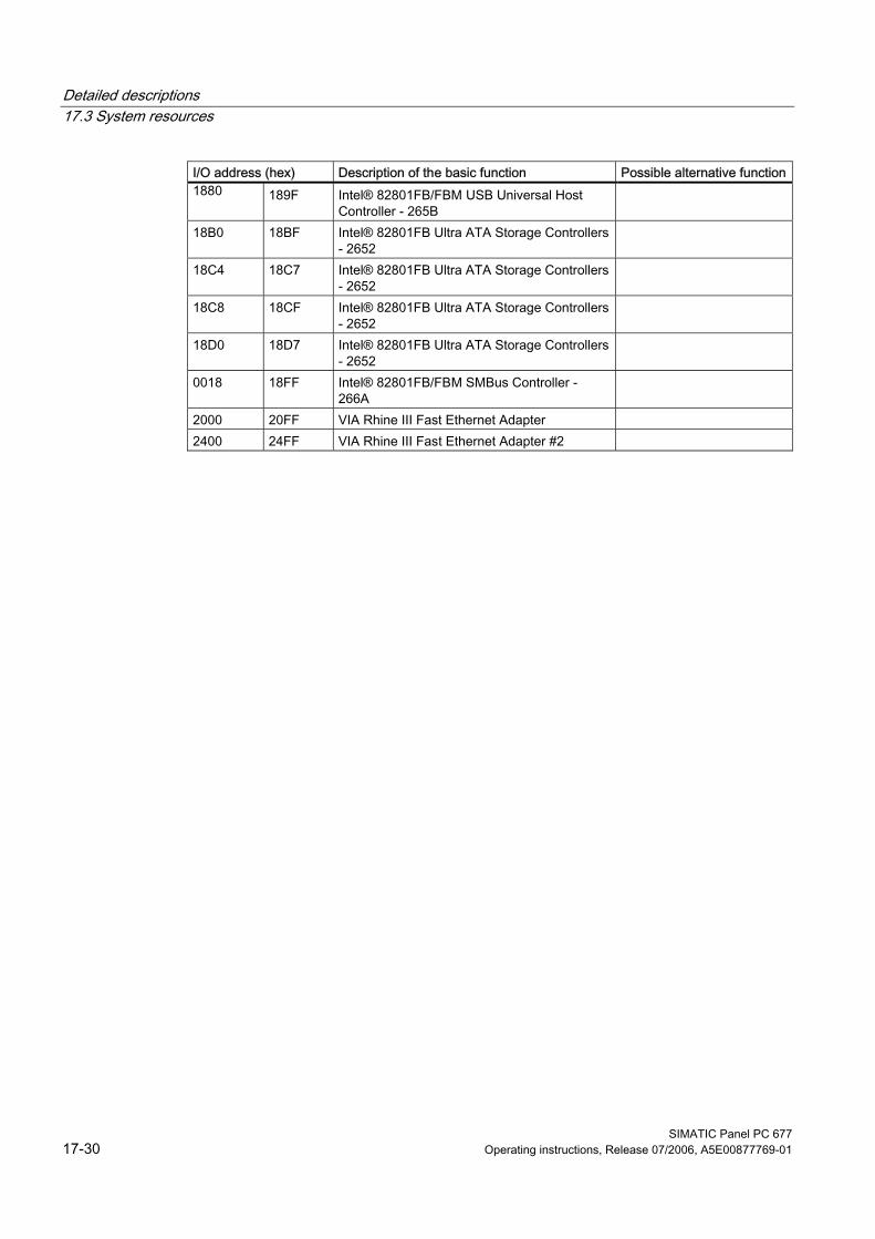
Detailed descriptions 17.3 System resources
SIMATIC Panel PC 677 17-30 Operating instructions, Release 07/2006, A5E00877769-01
I/O address (hex) Description of the basic function Possible alternative function1880 189F Intel® 82801FB/FBM USB Universal Host
Controller - 265B
18B0 18BF Intel® 82801FB Ultra ATA Storage Controllers - 2652
18C4 18C7 Intel® 82801FB Ultra ATA Storage Controllers - 2652
18C8 18CF Intel® 82801FB Ultra ATA Storage Controllers - 2652
18D0 18D7 Intel® 82801FB Ultra ATA Storage Controllers - 2652
0018 18FF Intel® 82801FB/FBM SMBus Controller - 266A
2000 20FF VIA Rhine III Fast Ethernet Adapter 2400 24FF VIA Rhine III Fast Ethernet Adapter #2
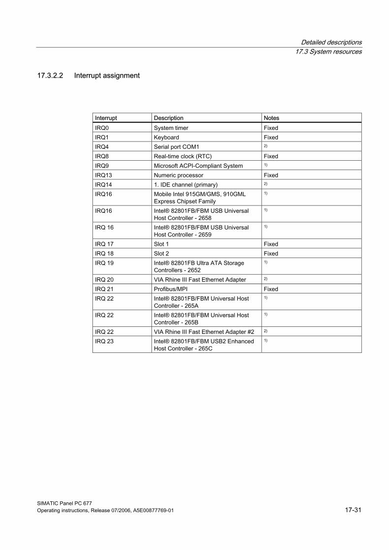
Detailed descriptions 17.3 System resources
SIMATIC Panel PC 677 Operating instructions, Release 07/2006, A5E00877769-01 17-31
17.3.2.2 Interrupt assignment
Interrupt Description Notes IRQ0 System timer Fixed IRQ1 Keyboard Fixed IRQ4 Serial port COM1 2) IRQ8 Real-time clock (RTC) Fixed IRQ9 Microsoft ACPI-Compliant System 1) IRQ13 Numeric processor Fixed IRQ14 1. IDE channel (primary) 2) IRQ16 Mobile Intel 915GM/GMS, 910GML
Express Chipset Family 1)
IRQ16 Intel® 82801FB/FBM USB Universal Host Controller - 2658
1)
IRQ 16 Intel® 82801FB/FBM USB Universal Host Controller - 2659
1)
IRQ 17 Slot 1 Fixed IRQ 18 Slot 2 Fixed IRQ 19 Intel® 82801FB Ultra ATA Storage
Controllers - 2652 1)
IRQ 20 VIA Rhine III Fast Ethernet Adapter 2) IRQ 21 Profibus/MPI Fixed IRQ 22 Intel® 82801FB/FBM Universal Host
Controller - 265A 1)
IRQ 22 Intel® 82801FB/FBM Universal Host Controller - 265B
1)
IRQ 22 VIA Rhine III Fast Ethernet Adapter #2 2) IRQ 23 Intel® 82801FB/FBM USB2 Enhanced
Host Controller - 265C 1)
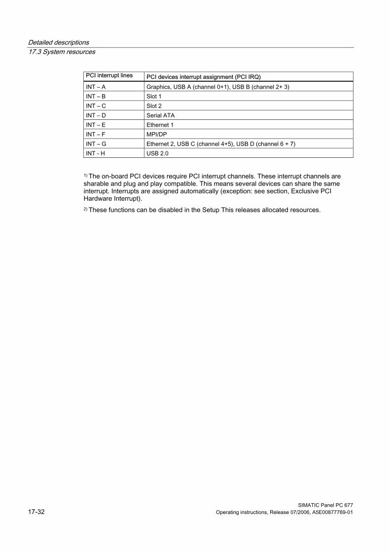
Detailed descriptions 17.3 System resources
SIMATIC Panel PC 677 17-32 Operating instructions, Release 07/2006, A5E00877769-01
PCI interrupt lines PCI devices interrupt assignment (PCI IRQ) INT – A Graphics, USB A (channel 0+1), USB B (channel 2+ 3) INT – B Slot 1 INT – C Slot 2 INT – D Serial ATA INT – E Ethernet 1 INT – F MPI/DP INT – G Ethernet 2, USB C (channel 4+5), USB D (channel 6 + 7) INT - H USB 2.0
1) The on-board PCI devices require PCI interrupt channels. These interrupt channels are sharable and plug and play compatible. This means several devices can share the same interrupt. Interrupts are assigned automatically (exception: see section, Exclusive PCI Hardware Interrupt). 2) These functions can be disabled in the Setup This releases allocated resources.
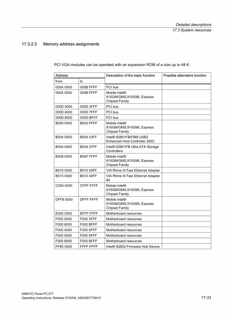
Detailed descriptions 17.3 System resources
SIMATIC Panel PC 677 Operating instructions, Release 07/2006, A5E00877769-01 17-33
17.3.2.3 Memory address assignments
PCI VGA modules can be operated with an expansion ROM of a size up to 48 K.
Address from to
Description of the basic function Possible alternative function
000A 0000 000B FFFF PCI bus 000A 0000 000B FFFF Mobile Intel®
915GM/GMS,910GML Express Chipset Family
000D 0000 000D 3FFF PCI bus 000D 4000 000D 7FFF PCI bus 000D 8000 000D BFFF PCI bus B000 0000 B003 FFFF Mobile Intel®
915GM/GMS,910GML Express Chipset Family
B004 0000 B004 03FF Intel® 82801FB/FBM USB2 Enhanced Host Controller 265C
B004 0400 B004 07FF Intel® 82801FB Ultra ATA Storage Controllers
B008 0000 B00F FFFF Mobile Intel® 915GM/GMS,910GML Express Chipset Family
B010 0000 B010 00FF VIA Rhine III Fast Ethernet Adapter B010 0400 B010 04FF VIA Rhine III Fast Ethernet Adapter
#2
C000 0000 CFFF FFFF Mobile Intel® 915GM/GMS,910GML Express Chipset Family
DFF8 0000 DFFF FFFF Mobile Intel® 915GM/GMS,910GML Express Chipset Family
E000 0000 EFFF FFFF Motherboard resources F000 0000 F000 3FFF Motherboard resources F000 8000 F000 BFFF Motherboard resources F000 4000 F000 4FFF Motherboard resources F000 5000 F000 5FFF Motherboard resources F000 8000 F000 BFFF Motherboard resources FF80 0000 FFFF FFFF Intel® 82802 Firmware Hub Device
Detailed descriptions 17.4 Operating system licenses
SIMATIC Panel PC 677 17-34 Operating instructions, Release 07/2006, A5E00877769-01
17.4 17.4 Operating system licenses Description: The supplied and installed Windows operating systems of the SIMATIC PCs are full Windows versions without any function restrictions. The additional wording "For Embedded Systems" on the accompanying operating system Recovery CD describes the contractual conditions under which Siemens AG acquires the licenses from Microsoft. The Microsoft Windows 2000 Professional MUI and Microsoft Windows XP Professional MUI operating systems supplied to Siemens AG under the license "Microsoft Operating Systems for Embedded Systems" for use with SIMATIC PG/PC products are equivalent to the relevant version from the desktop/office sales channel. This provides numerous advantages for customers in the industrial environment over the OEM licenses marketed in the office environment: • Long-term availability of operating systems up to 15 years, considerably longer than the
Microsoft marketing period for the office environment • No license for Windows XP Professional is required from Microsoft by the customer
(important when components are replaced during servicing) • In addition to the operating system CD (Recovery CD), the contract permits a Restore
DVD to be supplied (image of the operating system as delivered - including all relevant drivers and software)
• The license permits images created by a customer to be transferred to any number of SIMATIC PCs that are fitted with the relevant COA (Certificate of Authentificity) labels "for Embedded Systems"
• The COA label on the device is the only license verification required. An additional license agreement is not necessary
The license conditions in the operating system pack contain a reference to "restricted functionality". This note only refers to the application scope of this license and is defined for industrial applications, such as industrial controls, programming devices, information terminals, instruments, displays, Web panels, etc. These devices must not be primarily intended for use in domestic or office environments. The licenses "for Embedded Systems" must not be confused with the Windows embedded operating systems, such as Windows XPe (Windows XP embedded). These may also contain functional limitations that have been implemented in favor of reduced memory allocation for image generation.
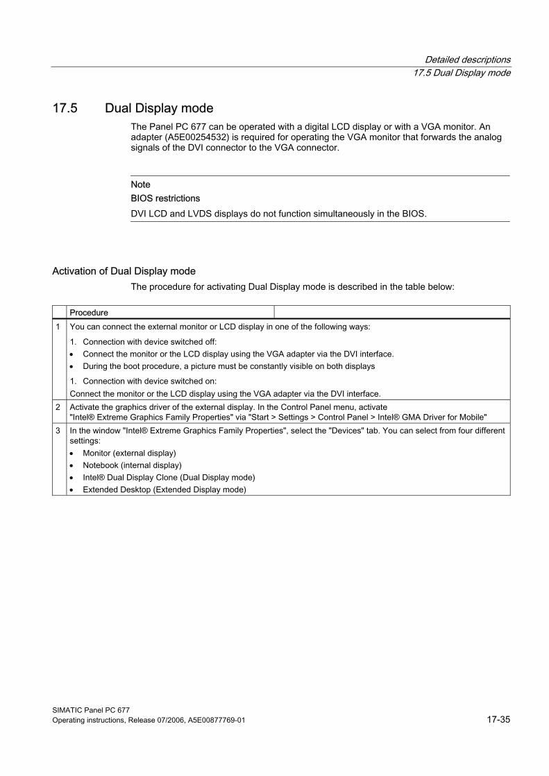
Detailed descriptions 17.5 Dual Display mode
SIMATIC Panel PC 677 Operating instructions, Release 07/2006, A5E00877769-01 17-35
17.5 17.5 Dual Display mode The Panel PC 677 can be operated with a digital LCD display or with a VGA monitor. An adapter (A5E00254532) is required for operating the VGA monitor that forwards the analog signals of the DVI connector to the VGA connector.
Note BIOS restrictions DVI LCD and LVDS displays do not function simultaneously in the BIOS.
Activation of Dual Display mode The procedure for activating Dual Display mode is described in the table below:
Procedure 1 You can connect the external monitor or LCD display in one of the following ways:
1. Connection with device switched off: • Connect the monitor or the LCD display using the VGA adapter via the DVI interface. • During the boot procedure, a picture must be constantly visible on both displays
1. Connection with device switched on: Connect the monitor or the LCD display using the VGA adapter via the DVI interface.
2 Activate the graphics driver of the external display. In the Control Panel menu, activate "Intel® Extreme Graphics Family Properties" via "Start > Settings > Control Panel > Intel® GMA Driver for Mobile"
3 In the window "Intel® Extreme Graphics Family Properties", select the "Devices" tab. You can select from four different settings: • Monitor (external display) • Notebook (internal display) • Intel® Dual Display Clone (Dual Display mode) • Extended Desktop (Extended Display mode)
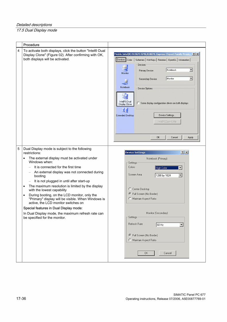
Detailed descriptions 17.5 Dual Display mode
SIMATIC Panel PC 677 17-36 Operating instructions, Release 07/2006, A5E00877769-01
Procedure 4 To activate both displays, click the button "Intel® Dual
Display Clone" (Figure 02). After confirming with OK, both displays will be activated.
5 Dual Display mode is subject to the following restrictions: • The external display must be activated under
Windows when: – It is connected for the first time – An external display was not connected during
booting – It is not plugged in until after start-up
• The maximum resolution is limited by the display with the lowest capability
• During booting, on the LCD monitor, only the "Primary" display will be visible. When Windows is active, the LCD monitor switches on
Special features in Dual Display mode: In Dual Display mode, the maximum refresh rate can be specified for the monitor.
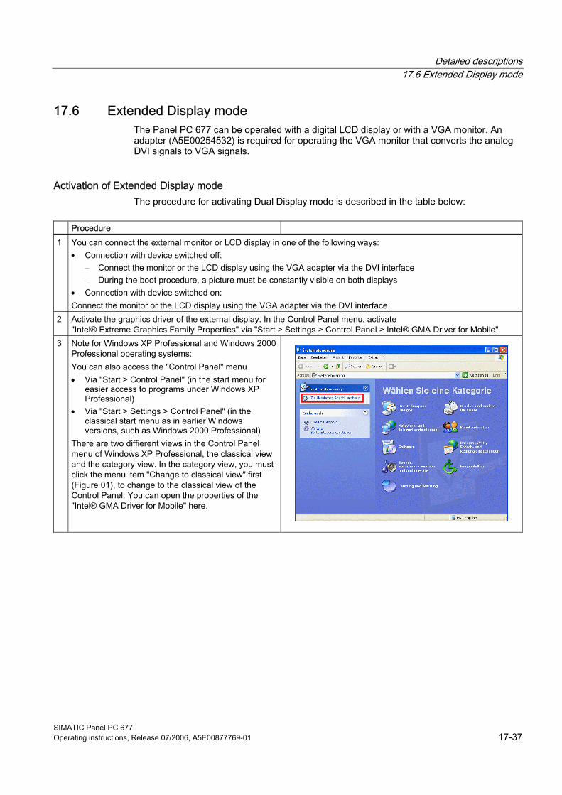
Detailed descriptions 17.6 Extended Display mode
SIMATIC Panel PC 677 Operating instructions, Release 07/2006, A5E00877769-01 17-37
17.6 17.6 Extended Display mode The Panel PC 677 can be operated with a digital LCD display or with a VGA monitor. An adapter (A5E00254532) is required for operating the VGA monitor that converts the analog DVI signals to VGA signals.
Activation of Extended Display mode The procedure for activating Dual Display mode is described in the table below:
Procedure 1 You can connect the external monitor or LCD display in one of the following ways:
• Connection with device switched off: – Connect the monitor or the LCD display using the VGA adapter via the DVI interface – During the boot procedure, a picture must be constantly visible on both displays
• Connection with device switched on: Connect the monitor or the LCD display using the VGA adapter via the DVI interface.
2 Activate the graphics driver of the external display. In the Control Panel menu, activate "Intel® Extreme Graphics Family Properties" via "Start > Settings > Control Panel > Intel® GMA Driver for Mobile"
3 Note for Windows XP Professional and Windows 2000 Professional operating systems: You can also access the "Control Panel" menu • Via "Start > Control Panel" (in the start menu for
easier access to programs under Windows XP Professional)
• Via "Start > Settings > Control Panel" (in the classical start menu as in earlier Windows versions, such as Windows 2000 Professional)
There are two diffierent views in the Control Panel menu of Windows XP Professional, the classical view and the category view. In the category view, you must click the menu item "Change to classical view" first (Figure 01), to change to the classical view of the Control Panel. You can open the properties of the "Intel® GMA Driver for Mobile" here.
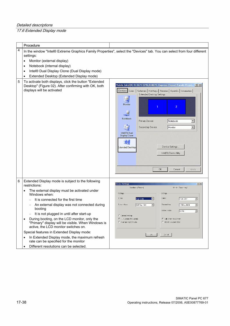
Detailed descriptions 17.6 Extended Display mode
SIMATIC Panel PC 677 17-38 Operating instructions, Release 07/2006, A5E00877769-01
Procedure 4 In the window "Intel® Extreme Graphics Family Properties", select the "Devices" tab. You can select from four different
settings: • Monitor (external display) • Notebook (internal display) • Intel® Dual Display Clone (Dual Display mode) • Extended Desktop (Extended Display mode)
5 To activate both displays, click the button "Extended Desktop" (Figure 02). After confirming with OK, both displays will be activated
6 Extended Display mode is subject to the following restrictions: • The external display must be activated under
Windows when: – It is connected for the first time – An external display was not connected during
booting – It is not plugged in until after start-up
• During booting, on the LCD monitor, only the "Primary" display will be visible. When Windows is active, the LCD monitor switches on.
Special features in Extended Display mode: • In Extended Display mode, the maximum refresh
rate can be specified for the monitor • Different resolutions can be selected.
Detailed descriptions 17.7 BIOS Setup
SIMATIC Panel PC 677 Operating instructions, Release 07/2006, A5E00877769-01 17-39
17.7 17.7 BIOS Setup
17.7.1 Overview
BIOS SETUP program The BIOS SETUP program is stored in the ROM BIOS. Information about the system configuration is stored in the battery-backed RAM of the device. You can use SETUP to set the hardware configuration (for example, the hard disk type) and define the system properties. You can also use SETUP to set the time-of-day and date.
Changing the device configuration Your device configuration is preset for working with the software supplied with the unit. You should only change the preset values if you have modified your device in any way, or if a fault occurs when the unit is powered up.
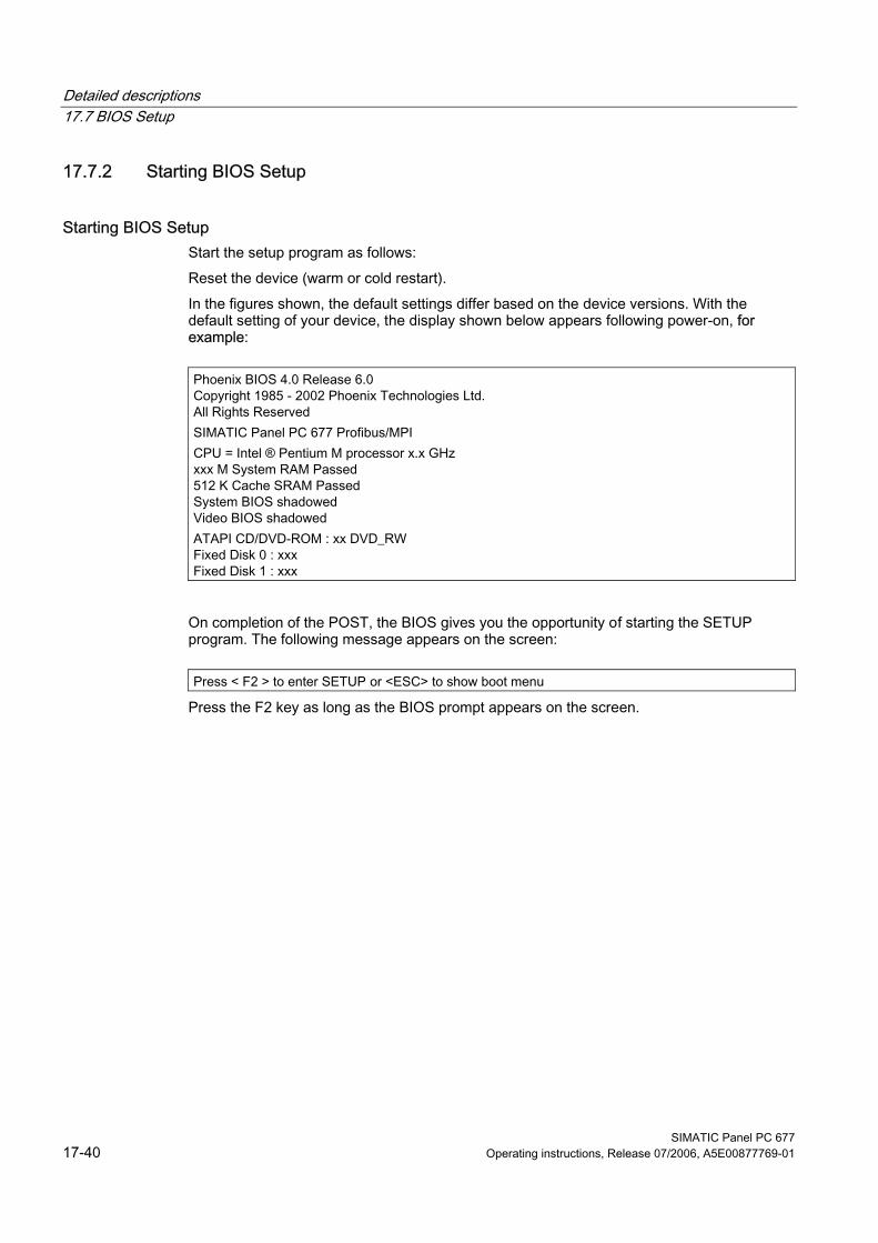
Detailed descriptions 17.7 BIOS Setup
SIMATIC Panel PC 677 17-40 Operating instructions, Release 07/2006, A5E00877769-01
17.7.2 Starting BIOS Setup
Starting BIOS Setup Start the setup program as follows: Reset the device (warm or cold restart). In the figures shown, the default settings differ based on the device versions. With the default setting of your device, the display shown below appears following power-on, for example:
Phoenix BIOS 4.0 Release 6.0 Copyright 1985 - 2002 Phoenix Technologies Ltd. All Rights Reserved SIMATIC Panel PC 677 Profibus/MPI CPU = Intel ® Pentium M processor x.x GHz xxx M System RAM Passed 512 K Cache SRAM Passed System BIOS shadowed Video BIOS shadowed ATAPI CD/DVD-ROM : xx DVD_RW Fixed Disk 0 : xxx Fixed Disk 1 : xxx
On completion of the POST, the BIOS gives you the opportunity of starting the SETUP program. The following message appears on the screen:
Press < F2 > to enter SETUP or <ESC> to show boot menu
Press the F2 key as long as the BIOS prompt appears on the screen.
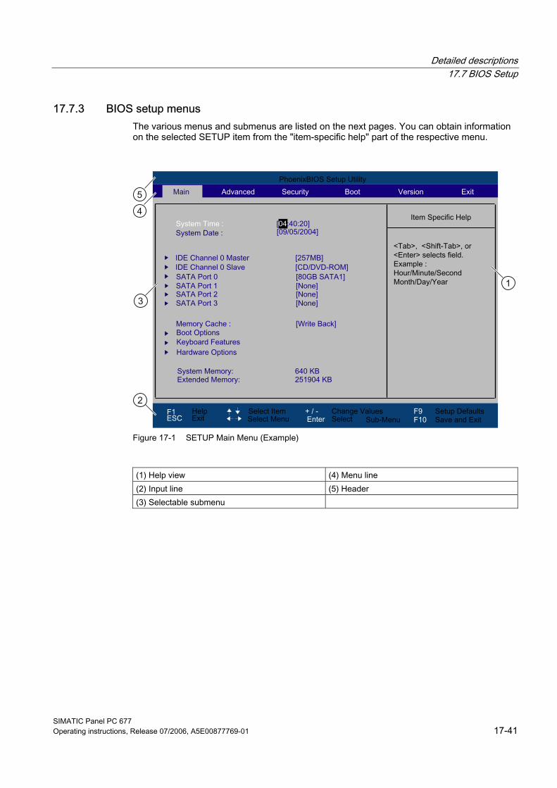
Detailed descriptions 17.7 BIOS Setup
SIMATIC Panel PC 677 Operating instructions, Release 07/2006, A5E00877769-01 17-41
17.7.3 BIOS setup menus The various menus and submenus are listed on the next pages. You can obtain information on the selected SETUP item from the "item-specific help" part of the respective menu.
Figure 17-1 SETUP Main Menu (Example)
(1) Help view (4) Menu line (2) Input line (5) Header (3) Selectable submenu
Detailed descriptions 17.7 BIOS Setup
SIMATIC Panel PC 677 17-42 Operating instructions, Release 07/2006, A5E00877769-01
Menu layout The screen is divided into four sections. In the top part (4), you can select the menu forms [Main], [Advanced], [Security], [Boot], [Version], [Exit]. In the left of the center section (3) you can select various settings or submenus. Brief help texts appear on the right (1) for the currently selected menu entry. The bottom section contains information for operator input. The figures below represent examples of specific device configurations. The screen content changes based on the supplied equipment configuration. Yellow stars to the left of the interface designation (for example, Internal COM 1) indicate a resource conflict between the interfaces managed by the BIOS. In this case you should select the default settings (F9) or eliminate the conflict. You can move between the menu forms using the cursor keys [←] left and [→] right.
Menu Meaning Main System functions are set here Advanced An extended system configuration can be set here Security Security functions are set here, for example, a password. Boot This is where the boot priority is specified. Version Information about the programming device (for example, release status) can be found
here. Exit Used for terminating and saving.
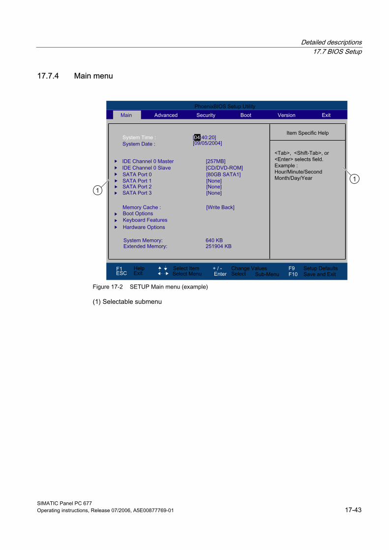
Detailed descriptions 17.7 BIOS Setup
SIMATIC Panel PC 677 Operating instructions, Release 07/2006, A5E00877769-01 17-43
17.7.4 Main menu
Figure 17-2 SETUP Main menu (example)
(1) Selectable submenu
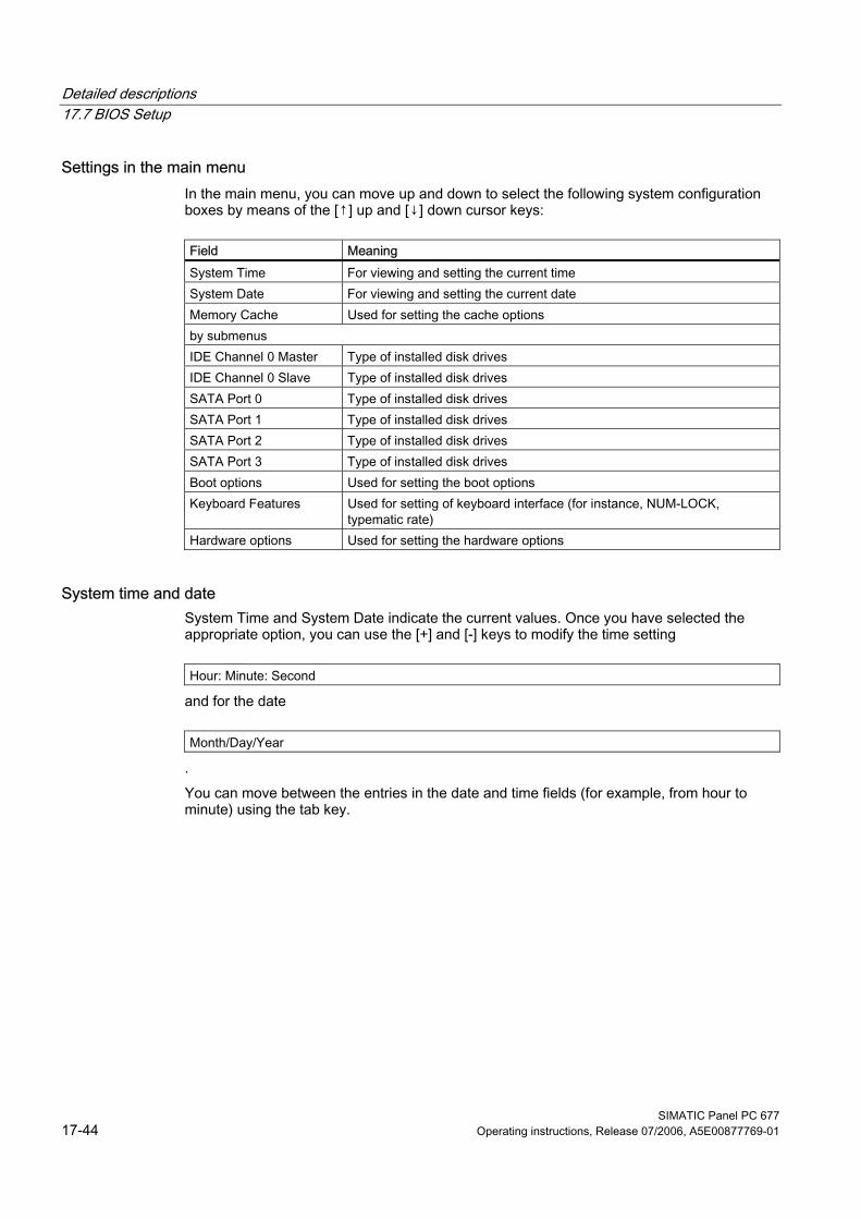
Detailed descriptions 17.7 BIOS Setup
SIMATIC Panel PC 677 17-44 Operating instructions, Release 07/2006, A5E00877769-01
Settings in the main menu In the main menu, you can move up and down to select the following system configuration boxes by means of the [↑] up and [↓] down cursor keys:
Field Meaning System Time For viewing and setting the current time System Date For viewing and setting the current date Memory Cache Used for setting the cache options by submenus IDE Channel 0 Master Type of installed disk drives IDE Channel 0 Slave Type of installed disk drives SATA Port 0 Type of installed disk drives SATA Port 1 Type of installed disk drives SATA Port 2 Type of installed disk drives SATA Port 3 Type of installed disk drives Boot options Used for setting the boot options Keyboard Features Used for setting of keyboard interface (for instance, NUM-LOCK,
typematic rate) Hardware options Used for setting the hardware options
System time and date System Time and System Date indicate the current values. Once you have selected the appropriate option, you can use the [+] and [-] keys to modify the time setting
Hour: Minute: Second
and for the date
Month/Day/Year
. You can move between the entries in the date and time fields (for example, from hour to minute) using the tab key.
Detailed descriptions 17.7 BIOS Setup
SIMATIC Panel PC 677 Operating instructions, Release 07/2006, A5E00877769-01 17-45
IDE Channel 0 Master, IDE Channel 0 Slave The system jumps to the following submenu when you select this type of menu field:
Figure 17-3 IDE Channel 0 Master (example)
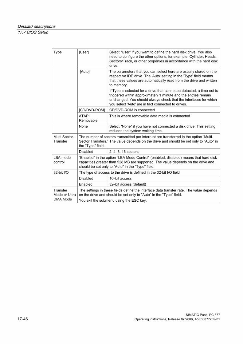
Detailed descriptions 17.7 BIOS Setup
SIMATIC Panel PC 677 17-46 Operating instructions, Release 07/2006, A5E00877769-01
[User] Select “User” if you want to define the hard disk drive. You also
need to configure the other options, for example, Cylinder, Heads, Sectors/Track, or other properties in accordance with the hard disk drive.
[Auto] The parameters that you can select here are usually stored on the respective IDE drive. The 'Auto' setting in the 'Type' field means that these values are automatically read from the drive and written to memory. If Type is selected for a drive that cannot be detected, a time-out is triggered within approximately 1 minute and the entries remain unchanged. You should always check that the interfaces for which you select 'Auto' are in fact connected to drives.
[CD/DVD-ROM] CD/DVD-ROM is connected ATAPI Removable
This is where removable data media is connected
Type
None Select "None" if you have not connected a disk drive. This setting reduces the system waiting time.
The number of sectors transmitted per interrupt are transferred in the option “Multi-Sector Transfers.” The value depends on the drive and should be set only to "Auto" in the "Type" field.
Multi Sector-Transfer
Disabled 2, 4, 8, 16 sectors LBA mode control
“Enabled” in the option “LBA Mode Control” (enabled, disabled) means that hard disk capacities greater than 528 MB are supported. The value depends on the drive and should be set only to "Auto" in the "Type" field. The type of access to the drive is defined in the 32-bit I/O field Disabled 16–bit access
32-bit I/O
Enabled 32–bit access (default) Transfer Mode or Ultra DMA Mode
The settings in these fields define the interface data transfer rate. The value depends on the drive and should be set only to "Auto" in the "Type" field. You exit the submenu using the ESC key.
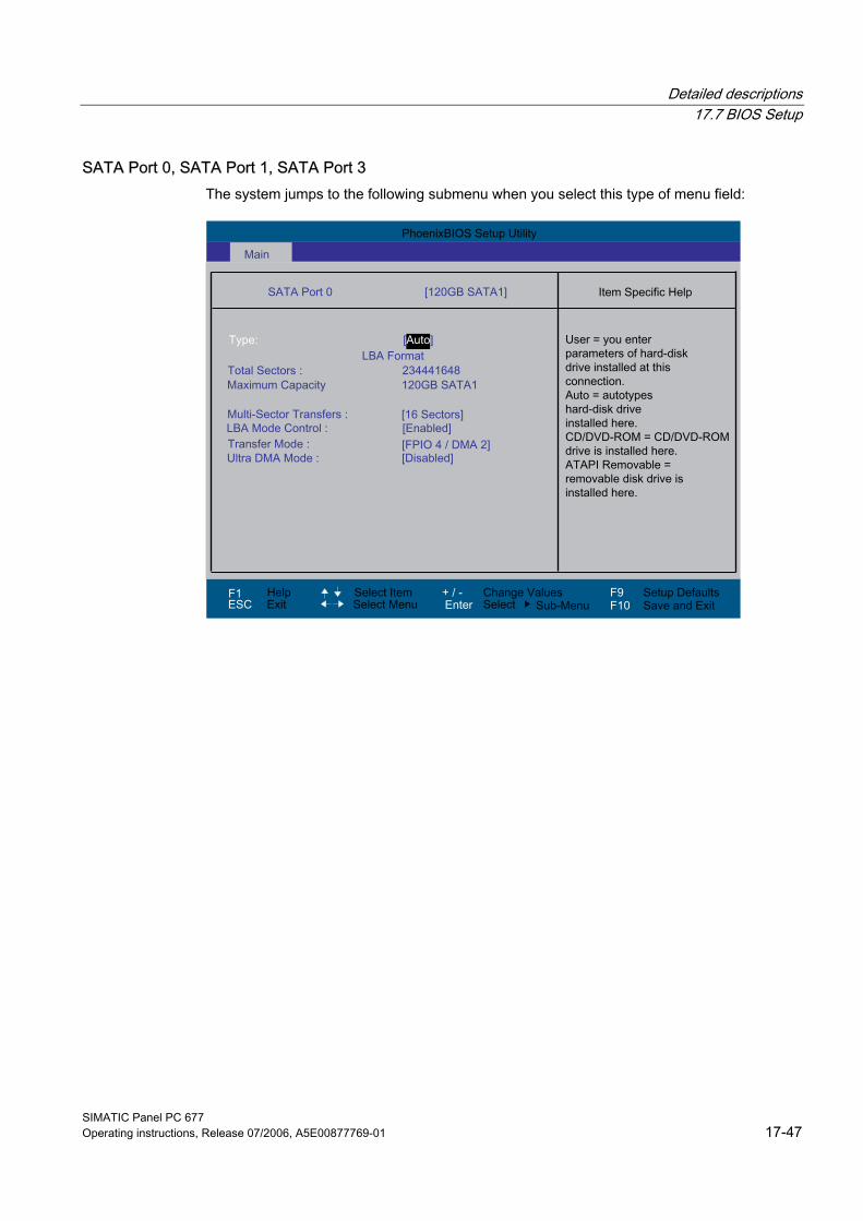
Detailed descriptions 17.7 BIOS Setup
SIMATIC Panel PC 677 Operating instructions, Release 07/2006, A5E00877769-01 17-47
SATA Port 0, SATA Port 1, SATA Port 3 The system jumps to the following submenu when you select this type of menu field:
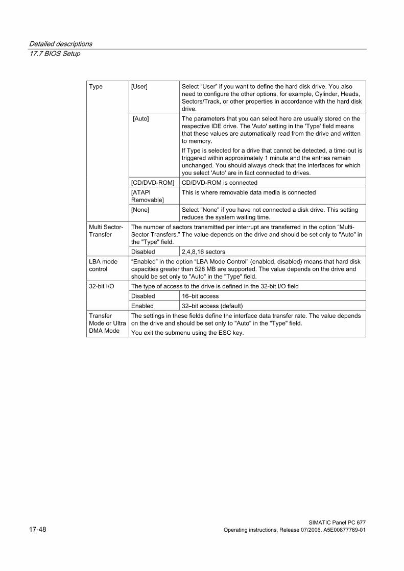
Detailed descriptions 17.7 BIOS Setup
SIMATIC Panel PC 677 17-48 Operating instructions, Release 07/2006, A5E00877769-01
[User] Select “User” if you want to define the hard disk drive. You also
need to configure the other options, for example, Cylinder, Heads, Sectors/Track, or other properties in accordance with the hard disk drive.
[Auto] The parameters that you can select here are usually stored on the respective IDE drive. The 'Auto' setting in the 'Type' field means that these values are automatically read from the drive and written to memory. If Type is selected for a drive that cannot be detected, a time-out is triggered within approximately 1 minute and the entries remain unchanged. You should always check that the interfaces for which you select 'Auto' are in fact connected to drives.
[CD/DVD-ROM] CD/DVD-ROM is connected [ATAPI Removable]
This is where removable data media is connected
Type
[None] Select "None" if you have not connected a disk drive. This setting reduces the system waiting time.
The number of sectors transmitted per interrupt are transferred in the option “Multi-Sector Transfers.” The value depends on the drive and should be set only to "Auto" in the "Type" field.
Multi Sector-Transfer
Disabled 2,4,8,16 sectors LBA mode control
“Enabled” in the option “LBA Mode Control” (enabled, disabled) means that hard disk capacities greater than 528 MB are supported. The value depends on the drive and should be set only to "Auto" in the "Type" field. The type of access to the drive is defined in the 32-bit I/O field Disabled 16–bit access
32-bit I/O
Enabled 32–bit access (default) Transfer Mode or Ultra DMA Mode
The settings in these fields define the interface data transfer rate. The value depends on the drive and should be set only to "Auto" in the "Type" field. You exit the submenu using the ESC key.
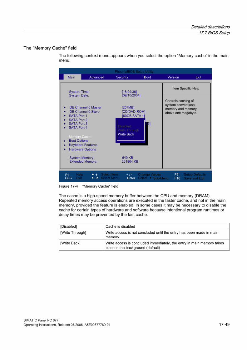
Detailed descriptions 17.7 BIOS Setup
SIMATIC Panel PC 677 Operating instructions, Release 07/2006, A5E00877769-01 17-49
The "Memory Cache" field The following context menu appears when you select the option “Memory cache” in the main menu:
Figure 17-4 "Memory Cache" field
The cache is a high-speed memory buffer between the CPU and memory (DRAM). Repeated memory access operations are executed in the faster cache, and not in the main memory, provided the feature is enabled. In some cases it may be necessary to disable the cache for certain types of hardware and software because intentional program runtimes or delay times may be prevented by the fast cache.
[Disabled] Cache is disabled [Write Through] Write access is not concluded until the entry has been made in main
memory [Write Back] Write access is concluded immediately, the entry in main memory takes
place in the background (default)

Detailed descriptions 17.7 BIOS Setup
SIMATIC Panel PC 677 17-50 Operating instructions, Release 07/2006, A5E00877769-01
"Boot options" field The following context menu appears when you select “Boot options” in the main menu:
Figure 17-5 "Boot Options" field
Quick Boot Mode Some hardware tests are skipped to speed up the boot sequence. SETUP prompt During the system load phase, the message "Press <F2> to enter Setup
or <Esc> to show boot menu" is output on the bottom of the screen. The boot sequence is stopped if an error is detected; you must press F1 to acknowledge. [Disabled] No error confirmation is required, for example, when no
keyboard is connected.
POST errors
[All, but not keyboard]
Show all errors except for keyboard errors.
Summary screen The most important system parameters are displayed when the system run-up phase completes.
Diagnostic screen Shows the diagnostics messages on the monitor during booting. Post Code/Status Specifies where the POST codes are saved.
'Enabled' means that the feature is active. 'Disabled' means that the feature is inactive.
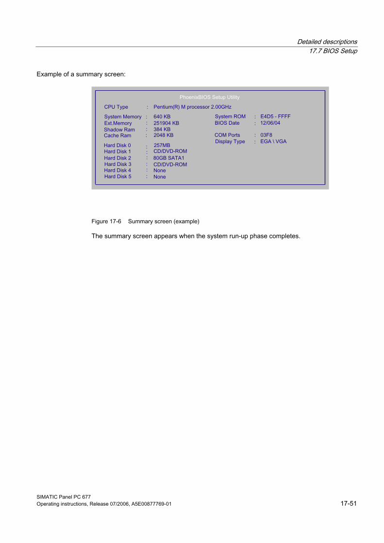
Detailed descriptions 17.7 BIOS Setup
SIMATIC Panel PC 677 Operating instructions, Release 07/2006, A5E00877769-01 17-51
Example of a summary screen:
Figure 17-6 Summary screen (example)
The summary screen appears when the system run-up phase completes.
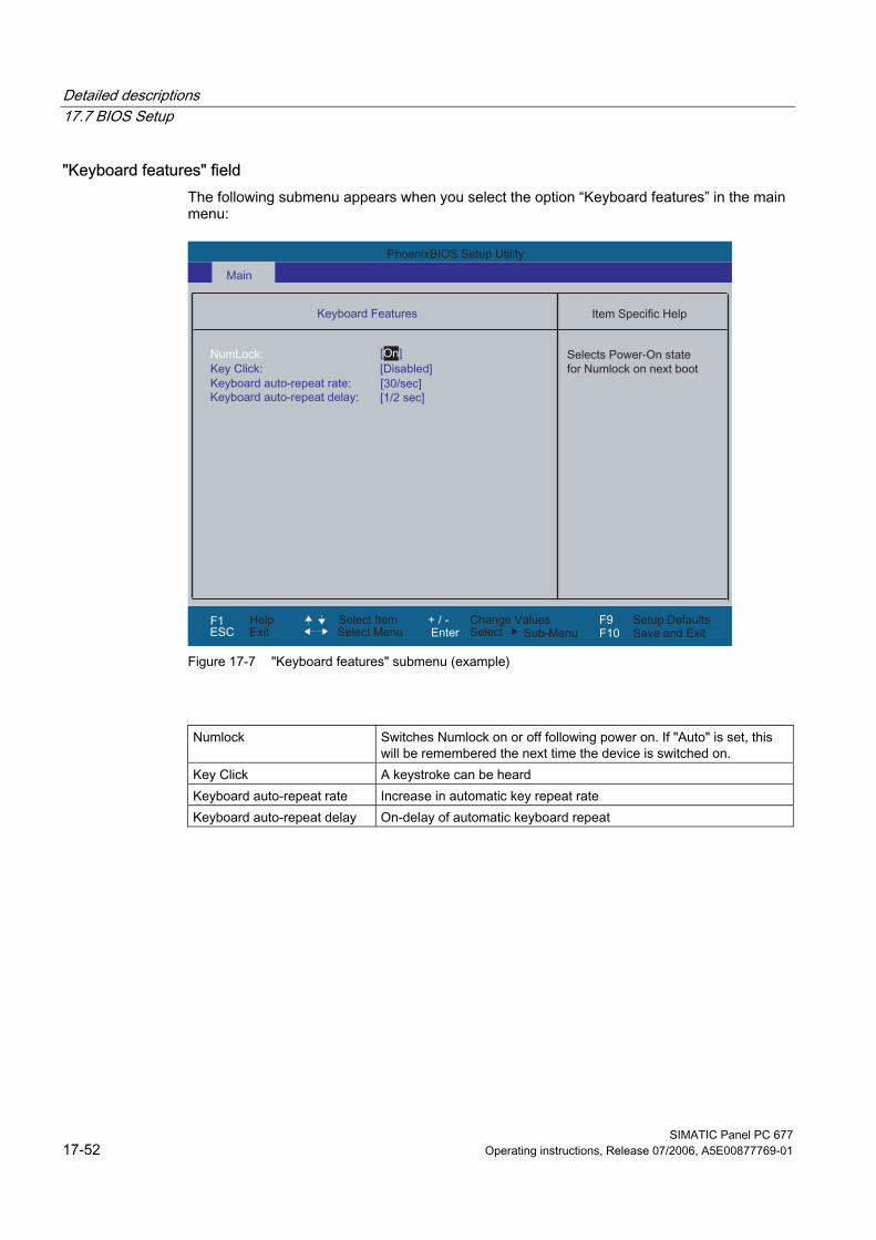
Detailed descriptions 17.7 BIOS Setup
SIMATIC Panel PC 677 17-52 Operating instructions, Release 07/2006, A5E00877769-01
"Keyboard features" field The following submenu appears when you select the option “Keyboard features” in the main menu:
Figure 17-7 "Keyboard features" submenu (example)
Numlock Switches Numlock on or off following power on. If "Auto" is set, this will be remembered the next time the device is switched on.
Key Click A keystroke can be heard Keyboard auto-repeat rate Increase in automatic key repeat rate Keyboard auto-repeat delay On-delay of automatic keyboard repeat
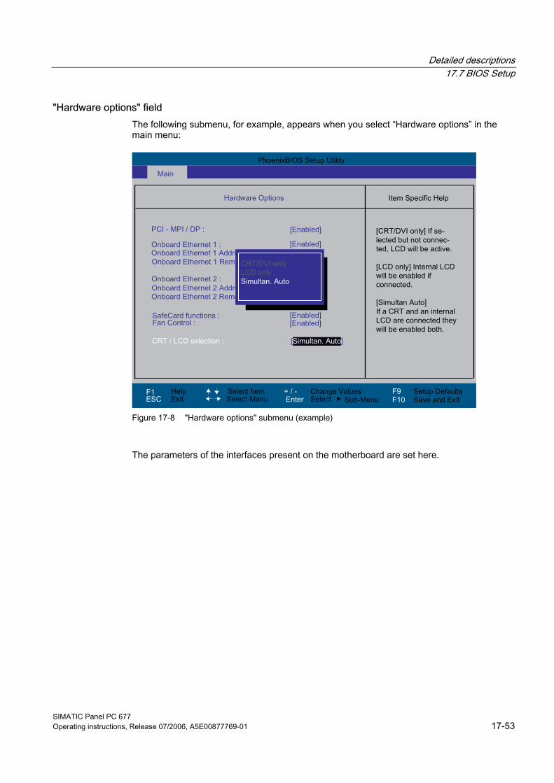
Detailed descriptions 17.7 BIOS Setup
SIMATIC Panel PC 677 Operating instructions, Release 07/2006, A5E00877769-01 17-53
"Hardware options" field The following submenu, for example, appears when you select “Hardware options” in the main menu:
Figure 17-8 "Hardware options" submenu (example)
The parameters of the interfaces present on the motherboard are set here.
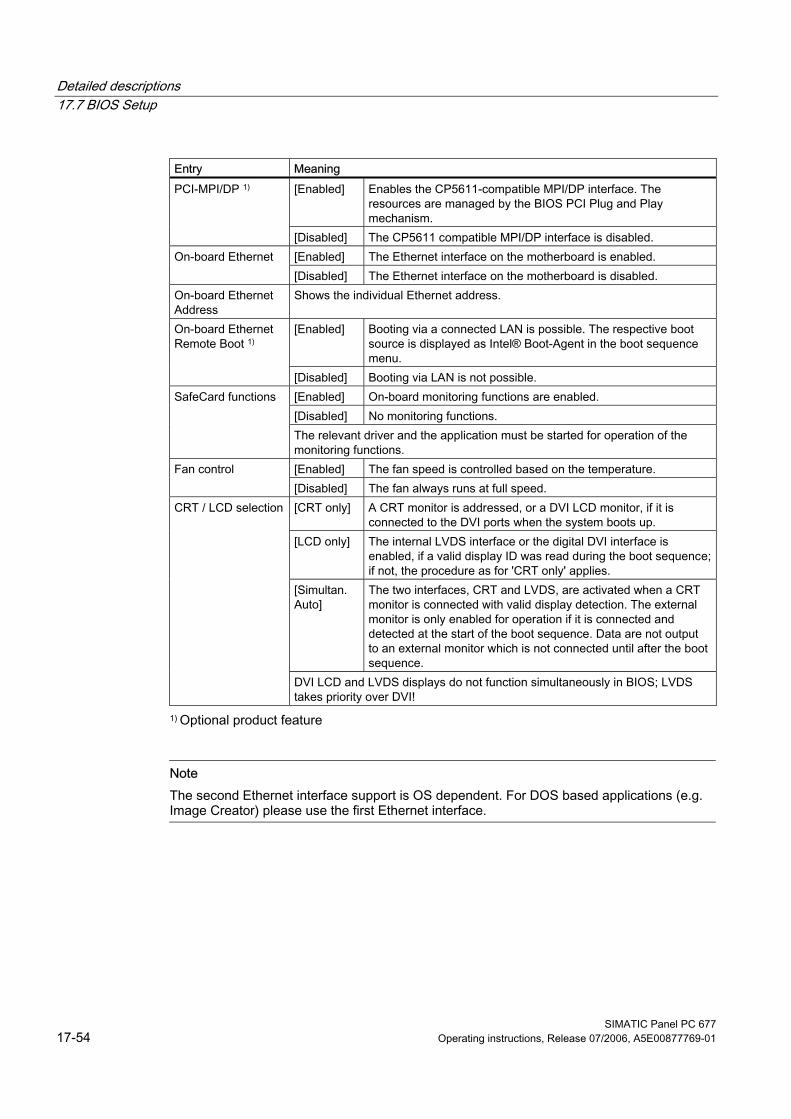
Detailed descriptions 17.7 BIOS Setup
SIMATIC Panel PC 677 17-54 Operating instructions, Release 07/2006, A5E00877769-01
Entry Meaning
[Enabled] Enables the CP5611-compatible MPI/DP interface. The resources are managed by the BIOS PCI Plug and Play mechanism.
PCI-MPI/DP 1)
[Disabled] The CP5611 compatible MPI/DP interface is disabled. [Enabled] The Ethernet interface on the motherboard is enabled. On-board Ethernet [Disabled] The Ethernet interface on the motherboard is disabled.
On-board Ethernet Address
Shows the individual Ethernet address.
[Enabled] Booting via a connected LAN is possible. The respective boot source is displayed as Intel® Boot-Agent in the boot sequence menu.
On-board Ethernet Remote Boot 1)
[Disabled] Booting via LAN is not possible. [Enabled] On-board monitoring functions are enabled. [Disabled] No monitoring functions.
SafeCard functions
The relevant driver and the application must be started for operation of the monitoring functions. [Enabled] The fan speed is controlled based on the temperature. Fan control [Disabled] The fan always runs at full speed. [CRT only] A CRT monitor is addressed, or a DVI LCD monitor, if it is
connected to the DVI ports when the system boots up. [LCD only] The internal LVDS interface or the digital DVI interface is
enabled, if a valid display ID was read during the boot sequence; if not, the procedure as for 'CRT only' applies.
[Simultan. Auto]
The two interfaces, CRT and LVDS, are activated when a CRT monitor is connected with valid display detection. The external monitor is only enabled for operation if it is connected and detected at the start of the boot sequence. Data are not output to an external monitor which is not connected until after the boot sequence.
CRT / LCD selection
DVI LCD and LVDS displays do not function simultaneously in BIOS; LVDS takes priority over DVI!
1) Optional product feature
Note The second Ethernet interface support is OS dependent. For DOS based applications (e.g. Image Creator) please use the first Ethernet interface.
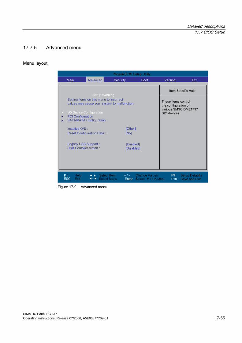
Detailed descriptions 17.7 BIOS Setup
SIMATIC Panel PC 677 Operating instructions, Release 07/2006, A5E00877769-01 17-55
17.7.5 Advanced menu
Menu layout
Figure 17-9 Advanced menu
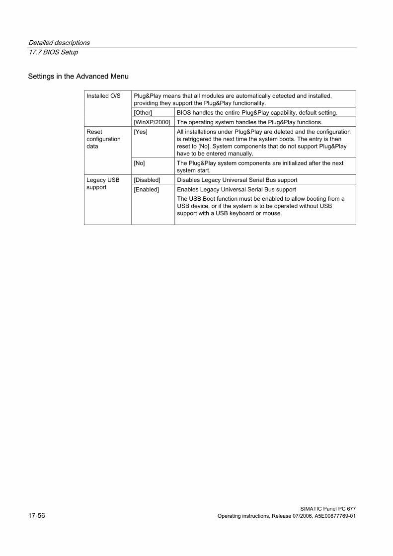
Detailed descriptions 17.7 BIOS Setup
SIMATIC Panel PC 677 17-56 Operating instructions, Release 07/2006, A5E00877769-01
Settings in the Advanced Menu
Plug&Play means that all modules are automatically detected and installed, providing they support the Plug&Play functionality. [Other] BIOS handles the entire Plug&Play capability, default setting.
Installed O/S
[WinXP/2000] The operating system handles the Plug&Play functions. [Yes] All installations under Plug&Play are deleted and the configuration
is retriggered the next time the system boots. The entry is then reset to [No]. System components that do not support Plug&Play have to be entered manually.
Reset configuration data
[No] The Plug&Play system components are initialized after the next system start.
[Disabled] Disables Legacy Universal Serial Bus support Legacy USB support [Enabled] Enables Legacy Universal Serial Bus support
The USB Boot function must be enabled to allow booting from a USB device, or if the system is to be operated without USB support with a USB keyboard or mouse.
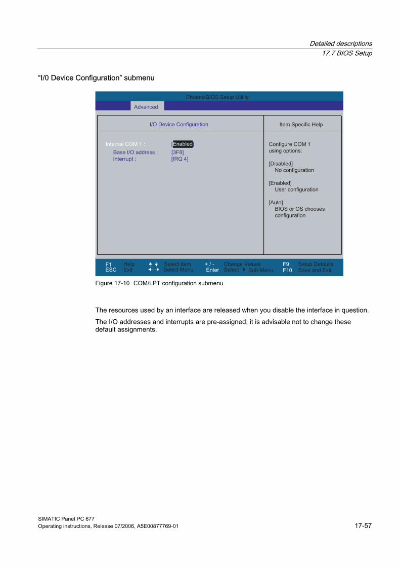
Detailed descriptions 17.7 BIOS Setup
SIMATIC Panel PC 677 Operating instructions, Release 07/2006, A5E00877769-01 17-57
“I/0 Device Configuration” submenu
Figure 17-10 COM/LPT configuration submenu
The resources used by an interface are released when you disable the interface in question. The I/O addresses and interrupts are pre-assigned; it is advisable not to change these default assignments.
Detailed descriptions 17.7 BIOS Setup
SIMATIC Panel PC 677 17-58 Operating instructions, Release 07/2006, A5E00877769-01
"PCI Configuration" submenu
Figure 17-11 PCI Configuration submenu (example)
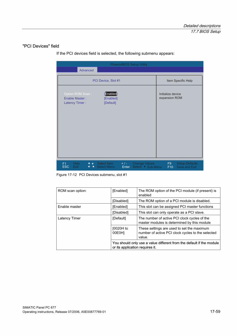
Detailed descriptions 17.7 BIOS Setup
SIMATIC Panel PC 677 Operating instructions, Release 07/2006, A5E00877769-01 17-59
"PCI Devices" field If the PCI devices field is selected, the following submenu appears:
Figure 17-12 PCI Devices submenu, slot #1
[Enabled] The ROM option of the PCI module (if present) is
enabled ROM scan option:
[Disabled] The ROM option of a PCI module is disabled. [Enabled] This slot can be assigned PCI master functions Enable master [Disabled] This slot can only operate as a PCI slave. [Default] The number of active PCI clock cycles of the
master modules is determined by this module [0020H to 00E0H]
These settings are used to set the maximum number of active PCI clock cycles to the selected value.
Latency Timer
You should only use a value different from the default if the module or its application requires it.
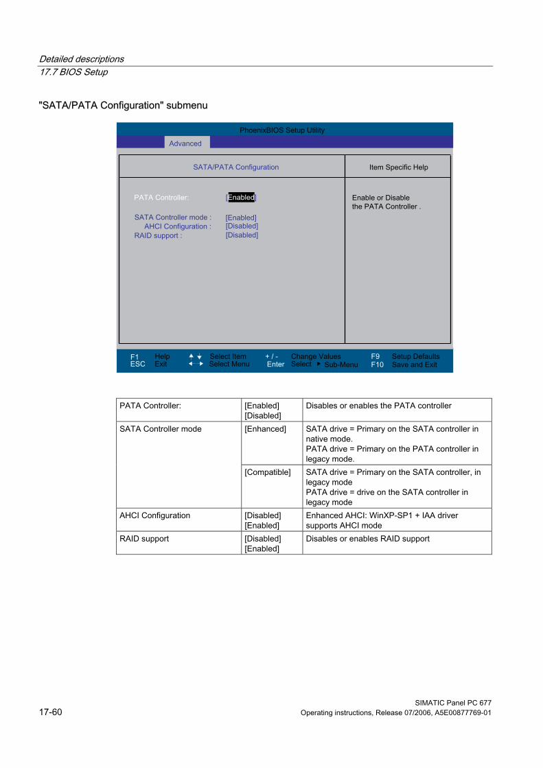
Detailed descriptions 17.7 BIOS Setup
SIMATIC Panel PC 677 17-60 Operating instructions, Release 07/2006, A5E00877769-01
"SATA/PATA Configuration" submenu
PATA Controller: [Enabled] [Disabled]
Disables or enables the PATA controller
[Enhanced] SATA drive = Primary on the SATA controller in native mode. PATA drive = Primary on the PATA controller in legacy mode.
SATA Controller mode
[Compatible] SATA drive = Primary on the SATA controller, in legacy mode PATA drive = drive on the SATA controller in legacy mode
AHCI Configuration [Disabled] [Enabled]
Enhanced AHCI: WinXP-SP1 + IAA driver supports AHCI mode
RAID support [Disabled] [Enabled]
Disables or enables RAID support
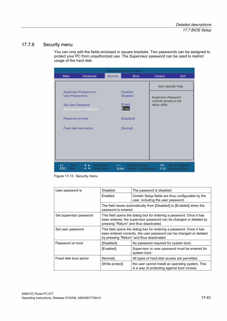
Detailed descriptions 17.7 BIOS Setup
SIMATIC Panel PC 677 Operating instructions, Release 07/2006, A5E00877769-01 17-61
17.7.6 Security menu You can only edit the fields enclosed in square brackets. Two passwords can be assigned to protect your PC from unauthorized use. The Supervisor password can be used to restrict usage of the hard disk.
Figure 17-13 Security menu
Disabled The password is disabled. Enabled Certain Setup fields are thus configurable by the
user, including the user password.
User password is
The field resets automatically from [Disabled] to [Enabled] when the password is entered.
Set supervisor password This field opens the dialog box for entering a password. Once it has been entered, the supervisor password can be changed or deleted by pressing ”Return” and thus deactivated.
Set user password This field opens the dialog box for entering a password. Once it has been entered correctly, the user password can be changed or deleted by pressing ”Return” and thus deactivated. [Disabled] No password required for system boot. Password on boot [Enabled] Supervisor or user password must be entered for
system boot. [Normal] All types of hard-disk access are permitted. Fixed disk boot sector [Write protect] the user cannot install an operating system. This
is a way of protecting against boot viruses.
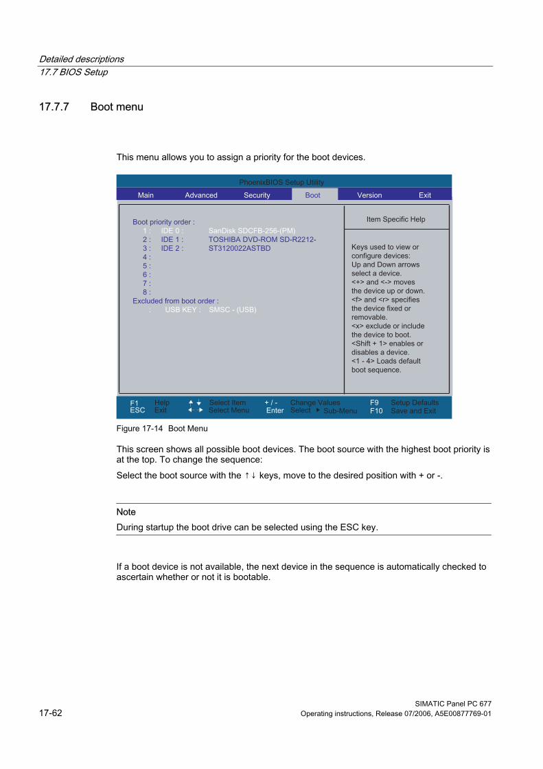
Detailed descriptions 17.7 BIOS Setup
SIMATIC Panel PC 677 17-62 Operating instructions, Release 07/2006, A5E00877769-01
17.7.7 Boot menu
This menu allows you to assign a priority for the boot devices.
Figure 17-14 Boot Menu
This screen shows all possible boot devices. The boot source with the highest boot priority is at the top. To change the sequence: Select the boot source with the ↑↓ keys, move to the desired position with + or -.
Note During startup the boot drive can be selected using the ESC key.
If a boot device is not available, the next device in the sequence is automatically checked to ascertain whether or not it is bootable.
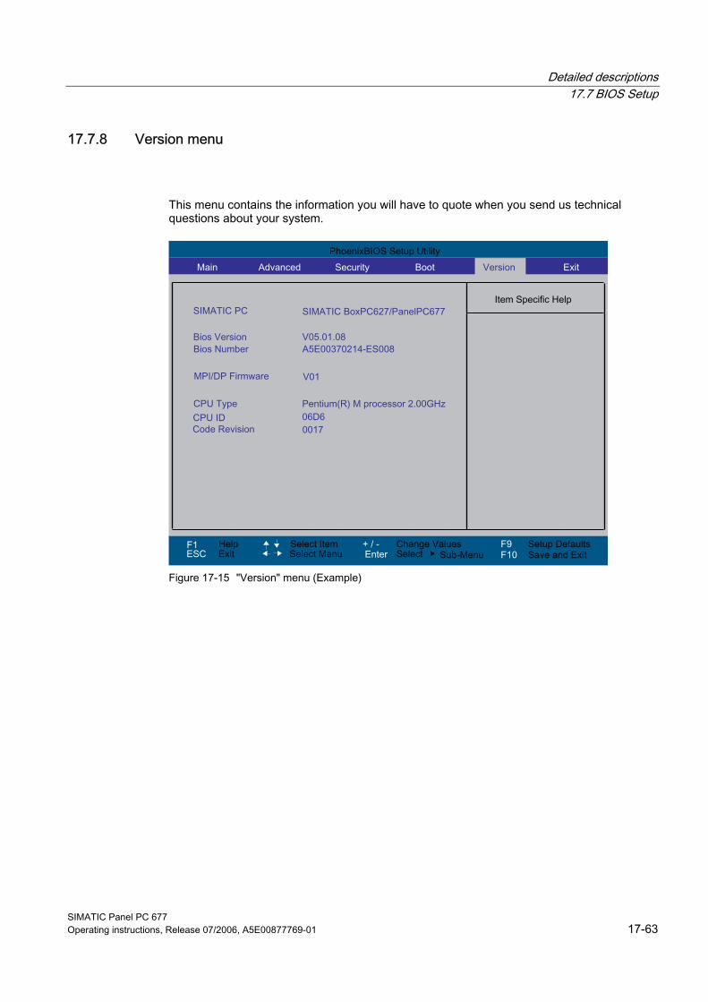
Detailed descriptions 17.7 BIOS Setup
SIMATIC Panel PC 677 Operating instructions, Release 07/2006, A5E00877769-01 17-63
17.7.8 Version menu
This menu contains the information you will have to quote when you send us technical questions about your system.
Figure 17-15 "Version" menu (Example)
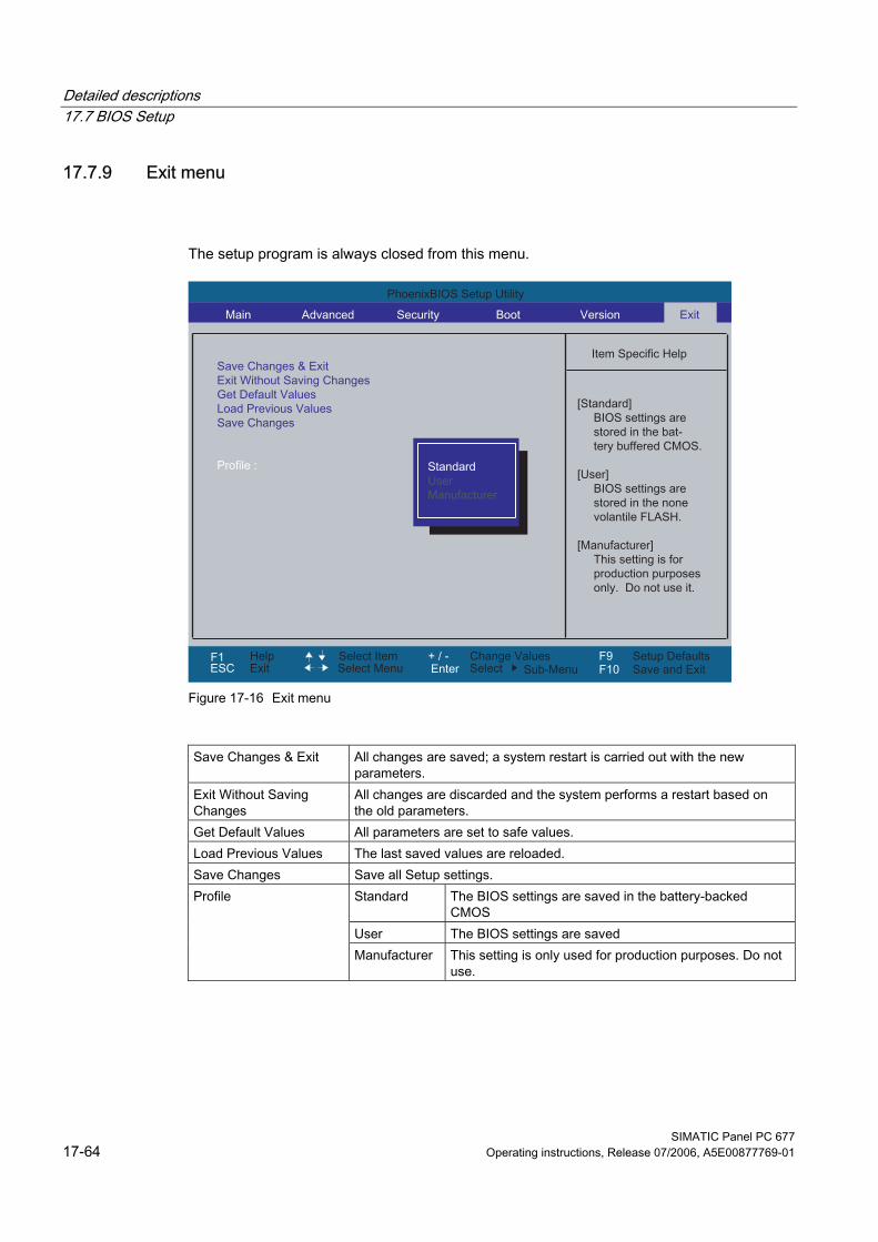
Detailed descriptions 17.7 BIOS Setup
SIMATIC Panel PC 677 17-64 Operating instructions, Release 07/2006, A5E00877769-01
17.7.9 Exit menu
The setup program is always closed from this menu.
Figure 17-16 Exit menu
Save Changes & Exit All changes are saved; a system restart is carried out with the new
parameters. Exit Without Saving Changes
All changes are discarded and the system performs a restart based on the old parameters.
Get Default Values All parameters are set to safe values. Load Previous Values The last saved values are reloaded. Save Changes Save all Setup settings.
Standard The BIOS settings are saved in the battery-backed CMOS
User The BIOS settings are saved
Profile
Manufacturer This setting is only used for production purposes. Do not use.
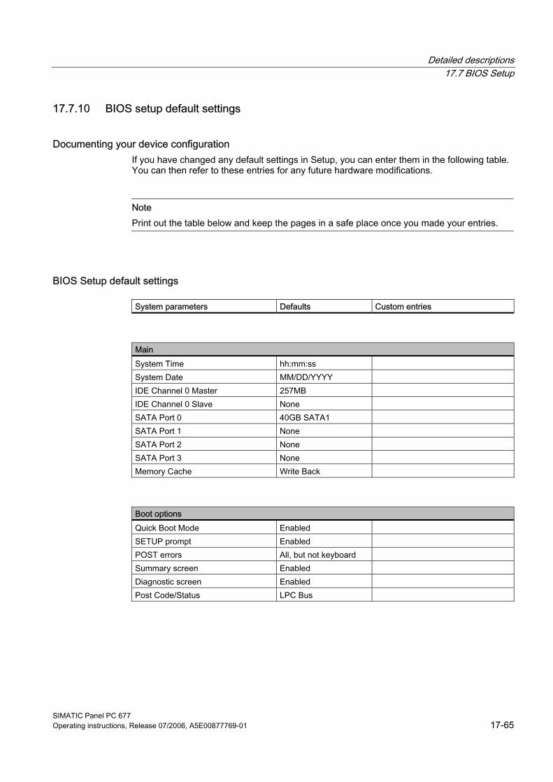
Detailed descriptions 17.7 BIOS Setup
SIMATIC Panel PC 677 Operating instructions, Release 07/2006, A5E00877769-01 17-65
17.7.10 BIOS setup default settings
Documenting your device configuration If you have changed any default settings in Setup, you can enter them in the following table. You can then refer to these entries for any future hardware modifications.
Note Print out the table below and keep the pages in a safe place once you made your entries.
BIOS Setup default settings
System parameters Defaults Custom entries
Main System Time hh:mm:ss System Date MM/DD/YYYY IDE Channel 0 Master 257MB IDE Channel 0 Slave None SATA Port 0 40GB SATA1 SATA Port 1 None SATA Port 2 None SATA Port 3 None Memory Cache Write Back
Boot options Quick Boot Mode Enabled SETUP prompt Enabled POST errors All, but not keyboard Summary screen Enabled Diagnostic screen Enabled Post Code/Status LPC Bus
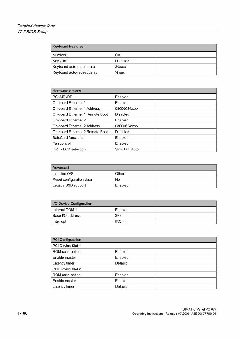
Detailed descriptions 17.7 BIOS Setup
SIMATIC Panel PC 677 17-66 Operating instructions, Release 07/2006, A5E00877769-01
Keyboard Features
Numlock On Key Click Disabled Keyboard auto-repeat rate 30/sec Keyboard auto-repeat delay ½ sec
Hardware options PCI-MPI/DP Enabled On-board Ethernet 1 Enabled On-board Ethernet 1 Address 08000624xxxx On-board Ethernet 1 Remote Boot Disabled On-board Ethernet 2 Enabled On-board Ethernet 2 Address 08000624xxxx On-board Ethernet 2 Remote Boot Disabled SafeCard functions Enabled Fan control Enabled CRT / LCD selection Simultan. Auto
Advanced Installed O/S Other Reset configuration data No Legacy USB support Enabled
I/O Device Configuration Internal COM 1 Enabled Base I/O address 3F8 Interrupt IRQ 4
PCI Configuration PCI Device Slot 1 ROM scan option: Enabled Enable master Enabled Latency timer Default PCI Device Slot 2 ROM scan option: Enabled Enable master Enabled Latency timer Default
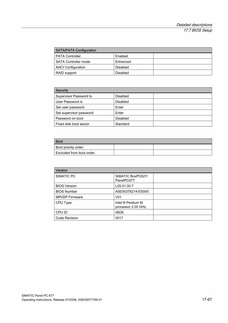
Detailed descriptions 17.7 BIOS Setup
SIMATIC Panel PC 677 Operating instructions, Release 07/2006, A5E00877769-01 17-67
SATA/PATA Configuration PATA Controller: Enabled SATA Controller mode Enhanced AHCI Configuration Disabled RAID support Disabled
Security Supervisor Password Is Disabled User Password is Disabled Set user password Enter Set supervisor password Enter Password on boot Disabled Fixed disk boot sector Standard
Boot Boot priority order: Excluded from boot order:
Version SIMATIC PC SIMATIC BoxPC627/
PanelPC677
BIOS Version L05.01.00.7 BIOS Number A5E00378214-ES000 MPI/DP Firmware V01 CPU Type Intel ® Pentium M
processor 2.00 GHz
CPU ID 06D6 Code Revision 0017
Detailed descriptions 17.7 BIOS Setup
SIMATIC Panel PC 677 17-68 Operating instructions, Release 07/2006, A5E00877769-01
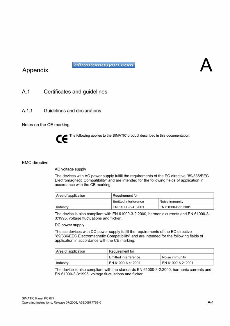
SIMATIC Panel PC 677 Operating instructions, Release 07/2006, A5E00877769-01 A-1
A Appendix AA.1 A.1 Certificates and guidelines
A.1.1 Guidelines and declarations
Notes on the CE marking
The following applies to the SIMATIC product described in this documentation:
EMC directive AC voltage supply The devices with AC power supply fulfill the requirements of the EC directive "89/336/EEC Electromagnetic Compatibility" and are intended for the following fields of application in accordance with the CE marking:
Area of application Requirement for Emitted interference Noise immunity Industry EN 61000-6-4: 2001 EN 61000-6-2: 2001
The device is also compliant with EN 61000-3-2:2000, harmonic currents and EN 61000-3-3:1995, voltage fluctuations and flicker. DC power supply Thesse devices with DC power supply fulfill the requirements of the EC directive "89/336/EEC Electromagnetic Compatibility" and are intended for the following fields of application in accordance with the CE marking:
Area of application Requirement for Emitted interference Noise immunity Industry EN 61000-6-4: 2001 EN 61000-6-2: 2001
The device is also compliant with the standards EN 61000-3-2:2000, harmonic currents and EN 61000-3-3:1995, voltage fluctuations and flicker.

Appendix A.1 Certificates and guidelines
SIMATIC Panel PC 677 A-2 Operating instructions, Release 07/2006, A5E00877769-01
Caution This is a system of Class A. The equipment may cause RF interference in residential areas. In this case, the operating company may be held liable for taking appropriate measures.
Low-voltage directive The device with AC power pack complies with the requirements of EC directive 73/23/EEC (Low-Voltage Guidelines). Compliance has been verified by a test in accordance with the EN 60950-1 standard. The device with DC power pack also complies with this standard but does not fall within the area of validity of the EU low-voltage directive.
Declaration of conformity The EC declaration of conformity and the corresponding documentation are made available to authorities in accordance with the EC directives stated above. The declaration of conformity can be downloaded at http://www.siemens.com/asis under "Support". Click on "Software Tools & Downloads" on "Overview Panel PCs" You can find the declaration under Approvals / Certificates.
Design guidelines Adhere to the installation guidelines and safety instructions given in this documentation during commissioning and operation.
Connecting peripherals The requirements regarding noise immunity to EN 61000-6-2:2001 are met when you connect a peripheral suitable for an industrial environment. Always use shielded cables to connect peripherals.
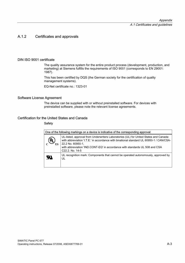
Appendix A.1 Certificates and guidelines
SIMATIC Panel PC 677 Operating instructions, Release 07/2006, A5E00877769-01 A-3
A.1.2 Certificates and approvals
DIN ISO 9001 certificate The quality assurance system for the entire product process (development, production, and marketing) at Siemens fulfills the requirements of ISO 9001 (corresponds to EN 29001: 1987). This has been certified by DQS (the German society for the certification of quality management systems). EQ-Net certificate no.: 1323-01
Software License Agreement The device can be supplied with or without preinstalled software. For devices with preinstalled software, please note the relevant license agreements.
Certification for the United States and Canada Safety
One of the following markings on a device is indicative of the corresponding approval:
UL-listed, approval from Underwriters Laboratories (UL) for United States and Canada: with abbreviation 'I.T.E.' in accordance with binational standard UL 60950-1 / CAN/CSA-22.2 No. 60950-1, with abbreviation 'IND.CONT-EQ' in accordance with standards UL 508 and CSA C22.2. No. 14-5
UL recognition mark: Components that cannot be operated autonomously, approved by UL
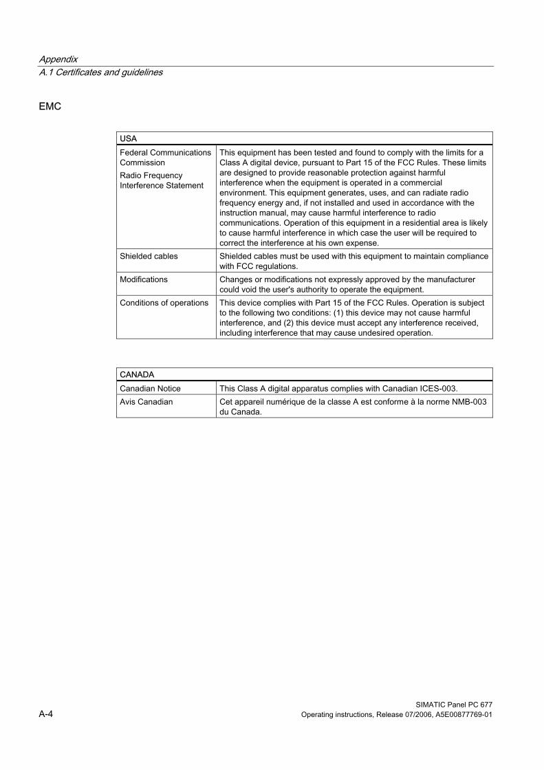
Appendix A.1 Certificates and guidelines
SIMATIC Panel PC 677 A-4 Operating instructions, Release 07/2006, A5E00877769-01
EMC
USA Federal Communications Commission Radio Frequency Interference Statement
This equipment has been tested and found to comply with the limits for a Class A digital device, pursuant to Part 15 of the FCC Rules. These limits are designed to provide reasonable protection against harmful interference when the equipment is operated in a commercial environment. This equipment generates, uses, and can radiate radio frequency energy and, if not installed and used in accordance with the instruction manual, may cause harmful interference to radio communications. Operation of this equipment in a residential area is likely to cause harmful interference in which case the user will be required to correct the interference at his own expense.
Shielded cables Shielded cables must be used with this equipment to maintain compliance with FCC regulations.
Modifications Changes or modifications not expressly approved by the manufacturer could void the user's authority to operate the equipment.
Conditions of operations This device complies with Part 15 of the FCC Rules. Operation is subject to the following two conditions: (1) this device may not cause harmful interference, and (2) this device must accept any interference received, including interference that may cause undesired operation.
CANADA Canadian Notice This Class A digital apparatus complies with Canadian ICES-003. Avis Canadian Cet appareil numérique de la classe A est conforme à la norme NMB-003
du Canada.
Appendix A.1 Certificates and guidelines
SIMATIC Panel PC 677 Operating instructions, Release 07/2006, A5E00877769-01 A-5
A.1.3 Further support Do you have additional questions regarding use of the described products, which are not answered in the documentation? Then, contact the Siemens representative or office nearest you. • Your contact:
http://www.siemens.com/automation/partner • Access to available technical documentation for individual SIMATIC products and
systems: http://www.siemens.com/simatic-tech-doku-portal
• Online catalog and online ordering system: http://mall.ad.siemens.com/
Training center To help you get started with automation technology and systems, we offer a variety of courses. Contact your regional training center or the central training center in D-90327 Nuremberg. Phone: +49 (911) 895-3200. Internet: http://www.sitrain.com
Technical Support You can access technical support for all A&D projects via the following: • Support Request form on the web:
http://www.siemens.com/automation/support-request • Phone: + 49 180 5050 222 • Fax: + 49 180 5050 223 Additional Technical Support information: http://www.siemens.com/automation/service.
Service & Support on the Internet In addition to our documentation, our complete know-how is available online on the Internet at: http://www.siemens.com/automation/service&support Here you will find: • Our newsletter containing up-to-date information on your products. • The documents you need via our Search function in Service & Support. • A forum for global information exchange by users and specialists. • You local Automation & Drives representative. • Information about on-site service, repairs, and spare parts. Much more can be found
under "Services".
Appendix A.1 Certificates and guidelines
SIMATIC Panel PC 677 A-6 Operating instructions, Release 07/2006, A5E00877769-01
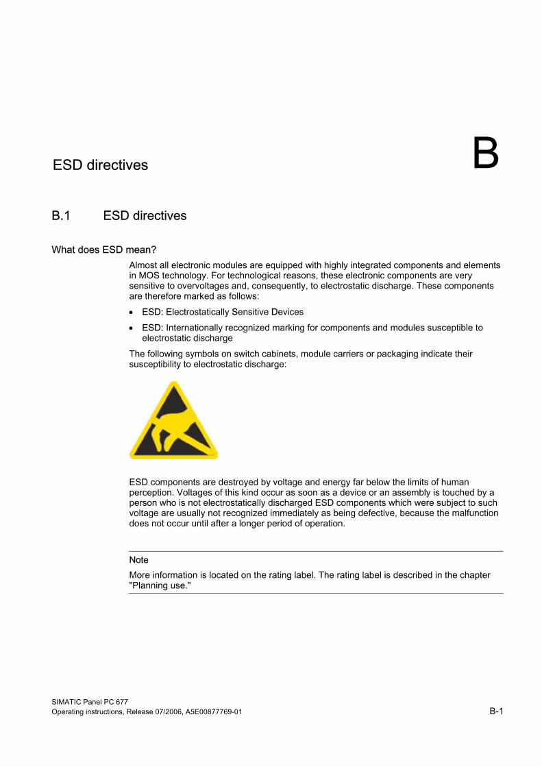
SIMATIC Panel PC 677 Operating instructions, Release 07/2006, A5E00877769-01 B-1
B ESD directives BB.1 B.1 ESD directives
What does ESD mean? Almost all electronic modules are equipped with highly integrated components and elements in MOS technology. For technological reasons, these electronic components are very sensitive to overvoltages and, consequently, to electrostatic discharge. These components are therefore marked as follows: • ESD: Electrostatically Sensitive Devices • ESD: Internationally recognized marking for components and modules susceptible to
electrostatic discharge The following symbols on switch cabinets, module carriers or packaging indicate their susceptibility to electrostatic discharge:
ESD components are destroyed by voltage and energy far below the limits of human perception. Voltages of this kind occur as soon as a device or an assembly is touched by a person who is not electrostatically discharged ESD components which were subject to such voltage are usually not recognized immediately as being defective, because the malfunction does not occur until after a longer period of operation.
Note More information is located on the rating label. The rating label is described in the chapter "Planning use."
ESD directives B.1 ESD directives
SIMATIC Panel PC 677 B-2 Operating instructions, Release 07/2006, A5E00877769-01
Precautions against electrostatic discharge Most plastics can be charged easily. Therefore, keep plastics away from ESD components! When working with electrostatically sensitive components, make sure that the person, the workstation and the packaging are properly grounded. Conduct the electrostatic charge away from your body by touching the mounting plate for the interfaces, for example.
Handling ESD modules As a rule: Only touch ESD components if unavoidable due to necessary tasks. Only touch the components when the following holds true: • You are permanently grounded by means of an ESD armband. • You are wearing ESD shoes or ESD shoes grounding protective strips in connection with
ESD floors. Before you touch an electronic assembly, your body must be discharged. Touch a conductive object immediately beforehand, e.g. a bare metal part of a switch cabinet or the water pipe. Do not allow chargeable, highly insulated materials, e.g. plastic films, insulating tabletops, synthetic clothing fibers, to come into contact with ESD components. Place ESD components only on conductive surfaces (work surfaces with ESD surface, conductive ESD foam, ESD packing bag, ESD transport container). Do not expose ESD components to visual display units, monitors or televisions. Maintain a distance of at least 10 cm to screens. Handle flat components only by their edges. Do not touch component connectors or conductors. This prevents charges from reaching and damaging sensitive components.
Measuring and modifying ESD components Measure the ESD component under the following conditions only: • The measuring device is grounded with a protective conductor, for example. • The probe on the potential-free measuring device has been discharged, e.g. by touching
the bare metal of a part of the switch cabinet. • Your body is discharged. To do so, touch a grounded metallic object. Solder only with grounded soldering irons.
Shipping ESD modules Always store or ship ESD components in conductive packaging, e.g. metallized plastic boxes or metal cans. Leave the components and parts in their packaging until installation. If the packaging is not conductive, wrap the ESD component in a conductive material, e.g. rubber foam, ESD bag, household aluminum foil, or paper, before packing. Do not wrap the ESD component in plastic bags or plastic film. In ESD components containing installed batteries, make sure that the conductive packaging does not touch the battery connectors or short circuit. Insulate the connectors with suitable material.
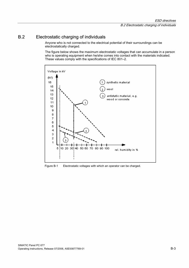
ESD directives B.2 Electrostatic charging of individuals
SIMATIC Panel PC 677 Operating instructions, Release 07/2006, A5E00877769-01 B-3
B.2 B.2 Electrostatic charging of individuals Anyone who is not connected to the electrical potential of their surroundings can be electrostatically charged. The figure below shows the maximum electrostatic voltages that can accumulate in a person who is operating equipment when he/she comes into contact with the materials indicated. These values comply with the specifications of IEC 801–2.
Figure B-1 Electrostatic voltages with which an operator can be charged.
ESD directives B.2 Electrostatic charging of individuals
SIMATIC Panel PC 677 B-4 Operating instructions, Release 07/2006, A5E00877769-01
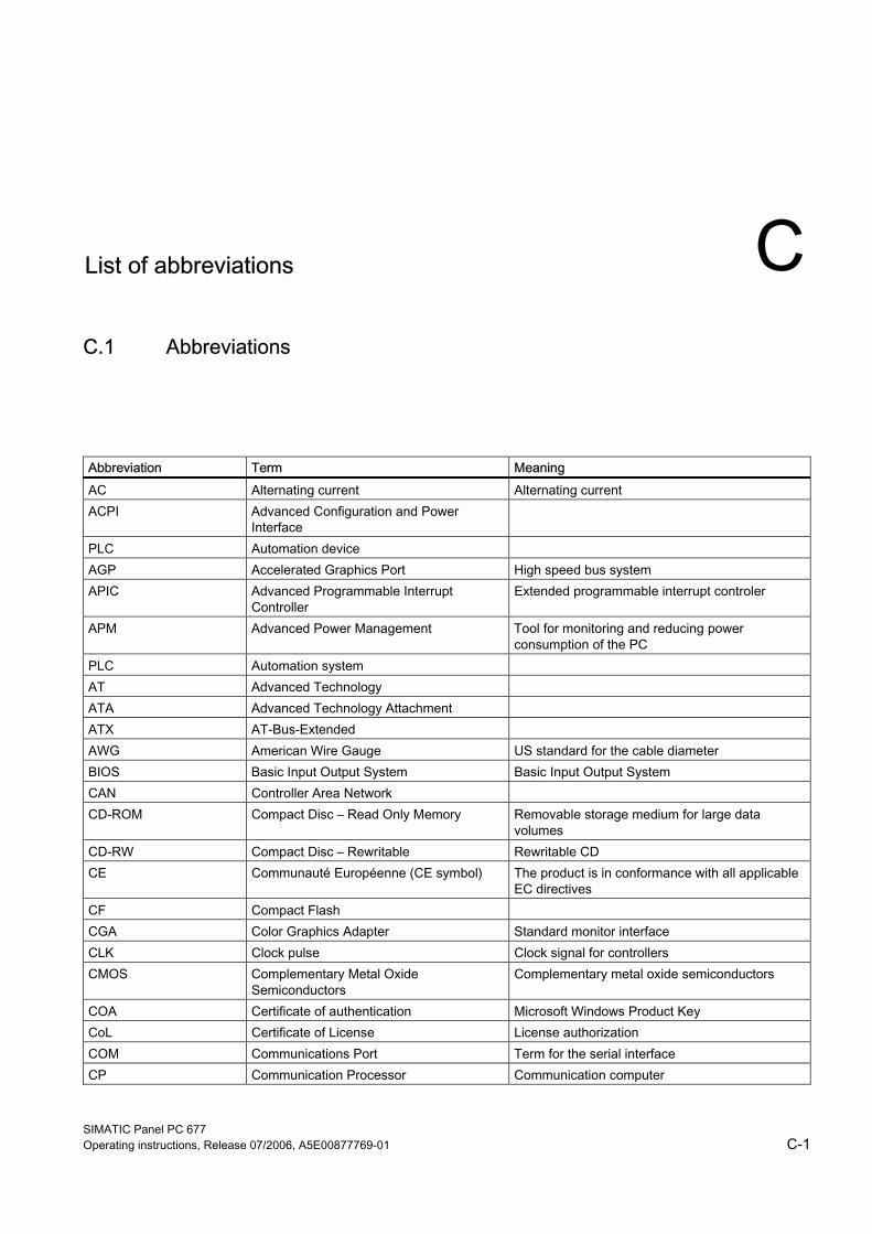
SIMATIC Panel PC 677 Operating instructions, Release 07/2006, A5E00877769-01 C-1
C List of abbreviations CC.1 C.1 Abbreviations
Abbreviation Term Meaning AC Alternating current Alternating current ACPI Advanced Configuration and Power
Interface
PLC Automation device AGP Accelerated Graphics Port High speed bus system APIC Advanced Programmable Interrupt
Controller Extended programmable interrupt controler
APM Advanced Power Management Tool for monitoring and reducing power consumption of the PC
PLC Automation system AT Advanced Technology ATA Advanced Technology Attachment ATX AT-Bus-Extended AWG American Wire Gauge US standard for the cable diameter BIOS Basic Input Output System Basic Input Output System CAN Controller Area Network CD-ROM Compact Disc – Read Only Memory Removable storage medium for large data
volumes CD-RW Compact Disc – Rewritable Rewritable CD CE Communauté Européenne (CE symbol) The product is in conformance with all applicable
EC directives CF Compact Flash CGA Color Graphics Adapter Standard monitor interface CLK Clock pulse Clock signal for controllers CMOS Complementary Metal Oxide
Semiconductors Complementary metal oxide semiconductors
COA Certificate of authentication Microsoft Windows Product Key CoL Certificate of License License authorization COM Communications Port Term for the serial interface CP Communication Processor Communication computer
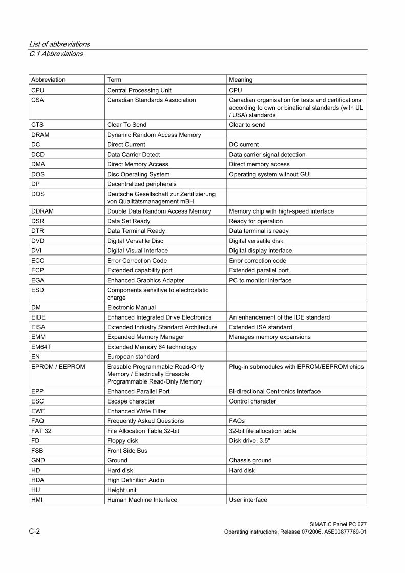
List of abbreviations C.1 Abbreviations
SIMATIC Panel PC 677 C-2 Operating instructions, Release 07/2006, A5E00877769-01
Abbreviation Term Meaning CPU Central Processing Unit CPU CSA Canadian Standards Association Canadian organisation for tests and certifications
according to own or binational standards (with UL / USA) standards
CTS Clear To Send Clear to send DRAM Dynamic Random Access Memory DC Direct Current DC current DCD Data Carrier Detect Data carrier signal detection DMA Direct Memory Access Direct memory access DOS Disc Operating System Operating system without GUI DP Decentralized peripherals DQS Deutsche Gesellschaft zur Zertifizierung
von Qualitätsmanagement mBH
DDRAM Double Data Random Access Memory Memory chip with high-speed interface DSR Data Set Ready Ready for operation DTR Data Terminal Ready Data terminal is ready DVD Digital Versatile Disc Digital versatile disk DVI Digital Visual Interface Digital display interface ECC Error Correction Code Error correction code ECP Extended capability port Extended parallel port EGA Enhanced Graphics Adapter PC to monitor interface ESD Components sensitive to electrostatic
charge
DM Electronic Manual EIDE Enhanced Integrated Drive Electronics An enhancement of the IDE standard EISA Extended Industry Standard Architecture Extended ISA standard EMM Expanded Memory Manager Manages memory expansions EM64T Extended Memory 64 technology EN European standard EPROM / EEPROM Erasable Programmable Read-Only
Memory / Electrically Erasable Programmable Read-Only Memory
Plug-in submodules with EPROM/EEPROM chips
EPP Enhanced Parallel Port Bi-directional Centronics interface ESC Escape character Control character EWF Enhanced Write Filter FAQ Frequently Asked Questions FAQs FAT 32 File Allocation Table 32-bit 32-bit file allocation table FD Floppy disk Disk drive, 3.5" FSB Front Side Bus GND Ground Chassis ground HD Hard disk Hard disk HDA High Definition Audio HU Height unit HMI Human Machine Interface User interface
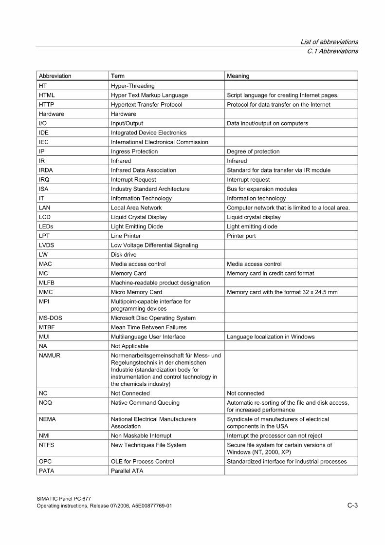
List of abbreviations C.1 Abbreviations
SIMATIC Panel PC 677 Operating instructions, Release 07/2006, A5E00877769-01 C-3
Abbreviation Term Meaning HT Hyper-Threading HTML Hyper Text Markup Language Script language for creating Internet pages. HTTP Hypertext Transfer Protocol Protocol for data transfer on the Internet Hardware Hardware I/O Input/Output Data input/output on computers IDE Integrated Device Electronics IEC International Electronical Commission IP Ingress Protection Degree of protection IR Infrared Infrared IRDA Infrared Data Association Standard for data transfer via IR module IRQ Interrupt Request Interrupt request ISA Industry Standard Architecture Bus for expansion modules IT Information Technology Information technology LAN Local Area Network Computer network that is limited to a local area. LCD Liquid Crystal Display Liquid crystal display LEDs Light Emitting Diode Light emitting diode LPT Line Printer Printer port LVDS Low Voltage Differential Signaling LW Disk drive MAC Media access control Media access control MC Memory Card Memory card in credit card format MLFB Machine-readable product designation MMC Micro Memory Card Memory card with the format 32 x 24.5 mm MPI Multipoint-capable interface for
programming devices
MS-DOS Microsoft Disc Operating System MTBF Mean Time Between Failures MUI Multilanguage User Interface Language localization in Windows NA Not Applicable NAMUR Normenarbeitsgemeinschaft für Mess- und
Regelungstechnik in der chemischen Industrie (standardization body for instrumentation and control technology in the chemicals industry)
NC Not Connected Not connected NCQ Native Command Queuing Automatic re-sorting of the file and disk access,
for increased performance NEMA National Electrical Manufacturers
Association Syndicate of manufacturers of electrical components in the USA
NMI Non Maskable Interrupt Interrupt the processor can not reject NTFS New Techniques File System Secure file system for certain versions of
Windows (NT, 2000, XP) OPC OLE for Process Control Standardized interface for industrial processes PATA Parallel ATA
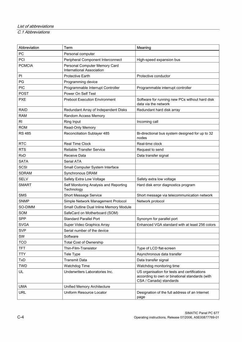
List of abbreviations C.1 Abbreviations
SIMATIC Panel PC 677 C-4 Operating instructions, Release 07/2006, A5E00877769-01
Abbreviation Term Meaning PC Personal computer PCI Peripheral Component Interconnect High-speed expansion bus PCMCIA Personal Computer Memory Card
International Association
PI Protective Earth Protective conductor PG Programming device PIC Programmable Interrupt Controller Programmable interrupt controller POST Power On Self Test PXE Preboot Execution Environment Software for running new PCs without hard disk
data via the network RAID Redundant Array of Independent Disks Redundant hard disk array RAM Random Access Memory RI Ring Input Incoming call ROM Read-Only Memory RS 485 Reconciliation Sublayer 485 Bi-directional bus system designed for up to 32
nodes RTC Real Time Clock Real-time clock RTS Reliable Transfer Service Request to send RxD Receive Data Data transfer signal SATA Serial ATA SCSI Small Computer System Interface SDRAM Synchronous DRAM SELV Safety Extra Low Voltage Safety extra low voltage SMART Self Monitoring Analysis and Reporting
Technology Hard disk error diagnostics program
SMS Short Message Service Short message via telecommunication network SNMP Simple Network Management Protocol Network protocol SO-DIMM Small Outline Dual Inline Memory Module SOM SafeCard on Motherboard (SOM) SPP Standard Parallel Port Synonym for parallel port SVGA Super Video Graphics Array Enhanced VGA standard with at least 256 colors SVP Serial number of the device SW Software TCO Total Cost of Ownership TFT Thin-Film-Transistor Type of LCD flat-screen TTY Tele Type Asynchronous data transfer TxD Transmit Data Data transfer signal TWD Watchdog Time Watchdog monitoring time UL Underwriters Laboratories Inc. US organisation for tests and certifications
according to own or binational standards (with CSA / Canada) standards
UMA Unified Memory Architecture URL Uniform Resource Locator Designation of the full address of an Internet
page
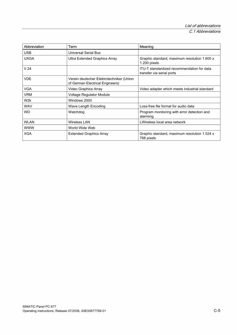
List of abbreviations C.1 Abbreviations
SIMATIC Panel PC 677 Operating instructions, Release 07/2006, A5E00877769-01 C-5
Abbreviation Term Meaning USB Universal Serial Bus UXGA Ultra Extended Graphics Array Graphic standard, maximum resolution 1.600 x
1.200 pixels V.24 ITU-T standardized recommendation for data
transfer via serial ports VDE Verein deutscher Elektrotechniker (Union
of German Electrical Engineers)
VGA Video Graphics Array Video adapter which meets industrial standard VRM Voltage Regulator Module W2k Windows 2000 WAV Wave Length Encoding Loss-free file format for audio data WD Watchdog Program monitoring with error detection and
alarming. WLAN Wireless LAN LWireless local area network WWW World Wide Web XGA Extended Graphics Array Graphic standard, maximum resolution 1.024 x
768 pixels
List of abbreviations C.1 Abbreviations
SIMATIC Panel PC 677 C-6 Operating instructions, Release 07/2006, A5E00877769-01
SIMATIC Panel PC 677 Operating instructions, Release 07/2006, A5E00877769-01 Glossary-1
Glossary
ATAPI CD–ROM Drive AT-Bus Attachment Packet Interface (connected to AT bus) CD-ROM drive
Automation device (AG) The programmable logical controllers (PLC) of the SIMATIC S5 system consist of a central controller, one or more CPUs, and various other modules (e.g. I/O modules).
Automation system (AS) The programmable logical controllers (PLC) of the SIMATIC S7 system consist of a central controller, one or more CPUs, and various I/O modules.
Backup Duplicate of a program, data carrier or database, used either for archiving purposes or for the protection of vital and non-replaceable data against loss when the working copy is corrupted. Some applications automatically generate backup copies of data files, and manage both the current and the previous versions on the hard disk.
Baud Physical unit for the step speed in signal transmission. Defines the number of transferred signal states per second. With only two states, one baud is equivalent to a transmission rate of 1 bps.
BEEP code If the BIOS detects a boot error, it outputs an audible warning based on the current test result
Boot diskette A diskette that contains a boot sector and an initial loader for the operating system. This can be used to load the operating system from the disk.
Booting Start or restart of the computer. During booting the operating system is transferred from the system data carrier to the work memory.
Glossary
SIMATIC Panel PC 677 Glossary-2 Operating instructions, Release 07/2006, A5E00877769-01
Cache High-speed access buffer for interim storage (buffering) of requested data.
CE marking Communauté Européene The CE symbol confirms the conformance of the product with all applicable EC directives, e.g. the EMC directive.
Chipset Located on the motherboard, connects the processor with the RAM, the graphic controller, the PCI bus, and the external interfaces.
Cold start A start sequence, starting when the computer is switched on. The system usually performs some basic hardware checks within the cold start sequence, and then loads the operating system from the hard disk to work memory -> boot
COM interface The COM interface is a serial V.24 interface. The interface is suitable for asynchronous data transfer.
Configuration files These are files containing data which define the configuration after restart. Examples of such files are CONFIG.SYS, AUTOEXEC.BAT and the registry files .
Configuration software The configuration software updates the device configuration when new modules are installed . This is done either by copying the configuration files supplied with the module or by manual configuration using the configuration utility.
Controller Integrated hardware and software controllers that control the functions of certain internal or peripheral devices (for example, the keyboard controller).
Device configuration The configuration of a PC or programming device contains information on hardware and device options, such as memory configuration, drive types, monitor, network address, etc. The data are stored in a configuration file and enable the operating system to load the correct device drivers and configure the correct device parameters. . If changes are made to the hardware configuration, the user can change entries in the configuration file using the SETUP program. .
Glossary
SIMATIC Panel PC 677 Operating instructions, Release 07/2006, A5E00877769-01 Glossary-3
Disc-at-once With this burning technique, data are written to a CD in a single session, and the CD is then closed. Further write access is then no longer possible.
Drivers Program parts of the operating system. They adapt user program data to the specific formats required by I/O devices such as hard disk, printers, and monitors.
EMC directive Directive concerning Electromagnetic Compatibility. Compliance is confirmed by the CE symbol and the EC certificate of conformity.
Energy management The energy management functions of a modern PC allow individual control over the current consumption of vital computer components (e.g. of the monitor, hard disk and CPU), by restricting their activity based on the current system or component load. Energy management is of particular importance for mobile PCs.
Energy options The energy options can be used to reduce energy consumption of the computer, while keeping it ready for immediate use. This can be configured in Windows by selecting Settings > Control Panel > Energy options.
ESD guidelines Directive for using electrostatic sensitive components.
Ethernet Local network (bus structure) for text and data communication with a transfer rate of 10/100 Mbps.
Formatting Basic partitioning of memory space on a magnetic data carrier into tracks and segments. Formatting deletes all data on a data carrier. All data carriers must be formatted prior to their first use.
Gender changer Using the gender changer (25-pin / 25-pin), the COM1/V24/AG interface of the SIMATIC PC family can be converted to the usual 25-pin male connector.
Glossary
SIMATIC Panel PC 677 Glossary-4 Operating instructions, Release 07/2006, A5E00877769-01
Hard disks Hard disks represent a form of magnetic disk storage medium (Winchester drives, hard disks) with integrated magnetic disks.
Hot swapping The SATA interface gives the device's hard drive system hot-swap capability. The prerequisite for this is a RAID1 system, comprising a SATA RAID controller (onboard or as a slot board, and at least two SATA swap frames. The advantage of hot swapping is that defective hard disks can be replaced without the need for rebooting.
Hub A term in network technology. In a network, a device joining communication lines at a central location, providing a common connection to all devices on the network.
Hyper Threading HT technology enables the parallel processing of tasks. HT is only effective when all relevant system components, such as processors, operating systems and applications are supported.
Image This refers to the image, for example, of hard disk partitions saved to a file in order to restore them when necessary.
Intel chip set 915 GM The chip set organizes the data traffic between the main processor, working memory, cache, slots and other interfaces. Functions of the 915 GM: Front side bus with 533 MHz, Intel® graphical media accelerator 900, support for up to 2 GB dual-channel DDR2 memories, Intel® High definition audio, Intel® display power-saving technology 2 (Intel® DPST 2)
Interface see Interface
Interface, multi-point MPI is the programming interface of SIMATIC S7/M7. Allows central access to programmable modules, text-based displays and OPs. The MPI nodes can intercommunicate.
Glossary
SIMATIC Panel PC 677 Operating instructions, Release 07/2006, A5E00877769-01 Glossary-5
LAN Local Area Network: LAN is a local network that consists of a group of computers and other devices that are distributed across a relatively restricted range and are linked with communication cables. The devices connected to a LAN are called nodes. The purpose of networks is the mutual use of files, printers or other resources.
Legacy USB support Support of USB devices (e.g. mouse, keyboard) on the USB ports without driver.
License key The license key represents the electronic license stamp of a license. Siemens provides the license keys for protected software.
License key diskette The license key diskette contains the authorizations or license keys required to enable protected SIMATIC software.
Low-voltage directive EC directive for product safety of products operated with low voltage (AC 50V to 1000V, DV 70V to 1500V) that are not governed by other directives. Compliance is confirmed by the CE symbol and the EC certificate of conformity.
LPT interface The LPT interface (Centronics interface) is a parallel interface that can be used to connect a printer.
Memory card Memory cards in credit card format. Memory for user programs and parameters, for example, for programmable modules and CPs.
Module Modules are plug-in units for PLCs, programming devices or PCs. They are available as local modules, expansion modules, interfaces or mass storage (Mass storage module).
Module bracket The module bracket is used to fasten modules and ensure safe contact and transport. Shocks and vibrations especially affect large, heavy modules. It is therefore recommended to use the module bracket for this type of module. There are also short, compact and light modules on the market. The module bracket was not designed for these modules because the standard fastening is sufficient for them.
Glossary
SIMATIC Panel PC 677 Glossary-6 Operating instructions, Release 07/2006, A5E00877769-01
Motherboard The motherboard is the core of the computer. Here, data are processed and stored, and interfaces and device I/Os are controlled and managed.
Operating system Summarizing term describing all functions for program execution, allocation of system resources to the various user programs, and for controlling and monitoring consistency of the operating mode in cooperation with the hardware (e.g. Windows XP Professional).
Packet writing The CD-RW is used as a diskette medium. The CD can then be read only by packet–writing compatible software or has to be finalized. Finalization of a CD closes the CD within an ISO9660 shell. You can still write to the CD-RW several times in spite of finalization. Not all CD drives can read packet-written CDs . There are restrictions to using this method in general data transfer.
PATA An interface for hard disk drives and optical drives with parallel data transfer of up to 100 Mbps.
PC card Trademark of the Personal Computer Memory Card International Association (PCMCIA). Designation for auxiliary cards that conform with PCMCIA specifications. A PC card that has roughly the size of a credit card can be plugged into a PCMCIA slot. Version 1 specifies cards of Type I with a thickness of 3.3 millimeters, which is conceived mainly for use as external memory. Version 2 of the PCMCIA specification also defines a card Type II with a thickness of 5 mm and a card of the Type III with a thickness of 10.5 mm. Type II cards can realize devices such as modems, fax and network interface cards. Type III cards are equipped with devices that require more space, for example wireless communication modules or rotary storage media (hard disks, for example).
PC/104 / PC/104-Plus Two bus architectures are especially fashionable today in the industrial world. PC/104 and PC/104-Plus. Both are standard in single-board computers of the PC class. The electrical and logical layout of the two bus systems is identical with ISA (PC/104) and PCI (PC/104-Plus). Software cannot usually detect a difference between them and normal desktop bus systems. Their advantage is the compact design and the resulting space they save.
PCMCIA Association consisting of approx. 450 member companies of the computer industry. Their focus is set on providing worldwide standards for miniaturization and flexible use of PC expansion cards, and thus to provide a basic technology to the market.
Glossary
SIMATIC Panel PC 677 Operating instructions, Release 07/2006, A5E00877769-01 Glossary-7
Pentium M Intel processor type: The architecture of the processor is designed for mobile computing; the processor features superior performance characteristics for computer applications and enhanced power-saving functions
Pixel PixElement (picture point). The pixel represents the smallest element that can be reproduced on-screen or on a printer.
Plug&Play Generally, a reference to the ability of a computer to automatically configure the system for communication with peripheral devices (for example monitors, modems or printers). The user can plug in a peripheral and ”play” it at once without manually configuring the system. A Plug&Play PC requires both a BIOS that supports Plug&Play and a Plug&Play expansion card.
POST Self-test performed by the BIOS after the computer is switched on. Performs a RAM test and a graphic controller test, for example. The system outputs audible signals (beep codes) if the BIOS detects any errors; the relevant message indicating cause of error is output on the screen.
PROFIBUS/MPI Process Field Bus (standard bus system for process applications)
PXE server A Preboot Execution Environment server is part of a network environment and can provide software to connected computers even before they boot. This can involve operating system installations or servicing tools, for example.
RAID Redundant Array of Independent Disks: Data storage system which is used to store data along with the error correction codes (e.g. parity bits) on at least two hard disks, in order to increase system reliability and performance. The hard disk array is controlled by management programs and a hard disk controller for error correction. The RAID system is usually implemented in network servers.
Recovery CD Contains the tools for setting up the hard disks and the Windows operating system.
Glossary
SIMATIC Panel PC 677 Glossary-8 Operating instructions, Release 07/2006, A5E00877769-01
Reset Hardware reset: Reset/restart of the PC using a button/switch.
Restart Warm start of a computer in operating state without switching off the power supply (Ctrl + Alt + Del)
Restore DVD The Restore DVD is used to restore the system partition or the entire hard disk to factory state if the system has crashed. The bootable DVD contains all the necessary image files. You can also create a boot disk allowing restoration via the network.
ROM Read-Only Memory ROM is a read-only memory in which every memory location can be addressed individually. The programs or data are permanently stored and are not lost in the event of a power failure.
SCSI interface Small Computer System Interface Interface for connecting SCSI devices (e.g. hard disk or optical drives)
Session at once In session at once, the CD can be written to both with an audio session and a data session. The two sessions are written to at once (as in disc at once).
SETUP (BIOS Setup) A program in which information about the device configuration (that is, the configuration of the hardware on the PC/PG) is defined. The device configuration of the PC/PG is preset with defaults. Changes must therefore be entered in the SETUP if a memory extension, new modules or a new drive are added to the hardware configuration.
Track-at-once In track-at-once recording, a CD can be written to in bits in several sessions if the CD was not closed.
Troubleshooting Error cause, cause analysis, remedy
Glossary
SIMATIC Panel PC 677 Operating instructions, Release 07/2006, A5E00877769-01 Glossary-9
V.24 interface The V.24 interface is a standardized interface for data transmission. Printers, modems, and other hardware modules can be connected to a V.24 interface
Warm restart The restart of a computer after a program was aborted. The operating system is loaded and restarted again. The hot key CTRL+ ALT+ DEL can be used to perform a warm start.
Windows Microsoft Windows is a multitasking graphical user interface. Windows provides a standard graphical interface based on drop-down menus, windowed regions on the screen, and allows operation with a pointer device such as a mouse.
WLAN Wireless LAN is a local network that transmits data via radio waves, infrared light or another wireless technology. Wireless LAN is mainly used in connection with mobile computers in the office or in factory environments.

Glossary
SIMATIC Panel PC 677 Glossary-10 Operating instructions, Release 07/2006, A5E00877769-01
SIMATIC Panel PC 677 Operating instructions, Release 07/2006, A5E00877769-01 Index-1
Index
< <Shift> key, 10-6
A Abbreviations, C-1 AC power supply, A-1 Accessories, 3-5 Advanced Menu
BIOS setup, 17-55 Alarms, 9-10, 9-11 Allocation of resources, 12-20 Approval, 1-1, 8-10 Approvals, A-3 Area of application, 1-1 Arithmetic symbols, 10-7
Entering, 10-7 Assignment
External interfaces, 17-5 I/O addresses, 17-28 Interrupts, 17-31 Memory addresses, 17-33 PCI IRQ channels, 17-22 Resources, 12-18
Authorization, 12-51 Automatic logon, 8-11 Automatic updates, 8-11, 9-10
B back up, 12-66
Hard disk drive, 12-66 Backlighting, 3-2 Battery replacement, 12-31 Beep codes, 13-3 BEEP codes, 13-5 BIOS, 8-9
Advanced Menu, 17-55 Beep codes, 13-5 BIOS settings, 8-9 Boot Menu, 17-62 Defaults, 17-65
Main menu, 17-44 Menu layout, 17-42 Security menu, 17-61 Setup, 17-39 Setup menus, 17-41
Boot options, 17-50 Boot sequence
Error messages, 13-1 Booting
Error messages, 13-1 Brief description, 3-1 Burning
CD-R / CD-RW, 9-17 Bus board
Design, 17-21 Removing, 12-36
C Cable connector, 12-8 Calibrating, 9-6
Touch screen, 9-6 CD-R / CD-RW
Operating notes, 9-17 CD-ROM, 15-3 CD-RW/DVD-ROM, 15-3 CE marking, 1-1, A-2 Certificates, A-3 Check list, 8-1 CheckLanguageID, 9-15 Chemical Resistance, 12-5 Clamping frame
Flat gasket, 5-6 Cleaning, 12-3
Front membrane, 12-3 Stainless steel front, 12-3
Cleaning agents, 12-1 Cleaning guidelines, 12-3, 12-6 Color display, 15-5 COM, 3-3 COM port
Interfaces, 3-3 COM/LPT configuration, 17-57 Commissioning, 2-4, 8-1
Device, 8-1
Index
SIMATIC Panel PC 677 Index-2 Operating instructions, Release 07/2006, A5E00877769-01
Compact Flash Detailed descriptions, 17-10 Installing/removing a card, 12-29 Partitioning, 12-29
Compact Flash Card, 3-3 Compatibility of the Restore DVD, 12-50 Components, 3-5 Computer unit, 12-8
Separating from the control unit, 12-8 Condensation, 2-4, 8-1 Connecting, 2-2, 7-2, 9-1, 10-9, A-2
Connecting external keyboard, 10-9 Device, 7-2 Electrical connection, 2-2 Peripherals, 9-1, A-2 S7 automation system, 7-2
Control elements, 10-3, 10-17 On the key panel, 10-3
Control unit, 3-2, 12-8 Separating from the computer unit, 12-8
Convention, 1-2 couple, 7-3
Device, 7-3 Coupling with SIMATIC S7, 7-1 Cover foil, 3-5 Cursor key, 10-8
D Dash, 10-7 Data exchange, 7-1 Date, 17-44
BIOS Setup, 17-44 DC power supply, A-1 Decimal point, 10-7 Defaults
BIOS, 17-65 Degree of protection, 4-10
IP54 degree of protection, 4-10 IP65 degree of protection, 4-10
Design, 3-2, 4-7, 4-14, 12-7, 15-5 Bus board, 17-21 Centralized configuration, 12-7 EMC compliant design, 4-14 Technical data for centralized configuration, 15-5
Design guidelines, A-2 Device, 4-14, 7-2, 7-3, 8-1, 9-1, 9-4, 12-1, 12-8, 12-10
Commissioning, 8-1 Connecting, 7-2 Connecting an S7 automation system, 7-2
couple, 7-3 EMC-compliant installation, 4-14 Interconnecting, 7-2 Interconnecting via MPI/PROFIBUS, 7-2 Maintaining, 12-1 opening, 12-14 Separating, 12-8, 12-10 Switching off, 9-4 Switching on, 9-1
Device configuration, 17-65 Device number, 4-3
Checking, 4-3 Device with stainless steel front
Installation, 5-6 DiagMonitor
Fan monitoring, 11-6 Temperature monitoring, 11-4
Diagnostics, 14-3 BIOS beep codes, 13-5 DiagMonitor, 11-1 SOM (Safecard On Motherboard), 11-1 Troubleshooting, 14-1
Dimension drawing, 16-2, 16-4 Dimensions, 4-11, 15-5, 16-2
Centralized configuration, 15-5 Panel PC 677, 16-2
Direct control key module, 3-5, 15-4 Disk drive, 3-4 Disk drives, 15-3 Display, 2-6, 3-1, 3-2
Interfaces, 17-11 TFT-LC display, 2-6
Distributed, 7-1 Download, 2-5 Drive bay module, 12-21
Removing, 12-23 Drivers, 12-58
Installing, 12-58 DVD ROM/CD RW
Removing, 12-24 DVD-ROM
Operating notes, 9-17 DVI interface, 17-8, 17-9 DVI-I, 3-3
E Electrical potential difference, 6-6 Electromagnetic compatibility, 4-14 Electrostatic charge, B-2, B-3
Precautions, B-2 Electrostatic Sensitive Components, B-1
Index
SIMATIC Panel PC 677 Operating instructions, Release 07/2006, A5E00877769-01 Index-3
Electrostatic Sensitive Devices, B-1 EMC, 4-14
Directive, 4-14 EMC compliant design, 4-14
EMC directive, A-1, A-4 AC power supply, A-1 DC power supply, A-1
Entering, 10-7 Arithmetic symbols, 10-7 Sign, 10-7 Special characters, 10-7
Equipment fan, 12-40, 12-42 Equipotential bonding, 6-6 Error, 14-3 Error messages
BIOS beep codes, 13-5 Booting, 13-1 Troubleshooting, 14-1
ESD, B-1, B-2 Directive, B-1 Electrostatic charging, B-3 Handling, B-2 Measuring, B-2 modify., B-2 Shipping, B-2
Ethernet, 3-3, 7-1 Ethernet address, 4-3 Exit, 8-8
Startup, 8-8 Expansion
Memory, 12-15 Expansion slots, 15-2 Extension
Module, 12-19 PCI/AT cards, 12-19
External interfaces, 17-5
F Factory state, 12-51 Fans
Monitoring, 11-6 Removal, 12-40, 12-42
FAQs, 14-3 Fault diagnostics, 13-3 Field devices, 7-1 Field of application, 4-1 Firewall, 9-10 Flat gasket, 5-6 Front membrane, 12-3, 12-5
Cleaning, 12-3 Function key, 3-2, 10-14
Labeling, 10-14 Function keys, 10-4
G Graphic, 3-3
H Hard disk, 3-4
Removing, 12-25 Hard disk drive, 12-66, 15-3
back up, 12-66 Hardware components, 8-4
additional hardware components, 8-4 Hardware options, 17-53
BIOS setup, 17-53 Heat-conductive paste, 12-46 Hotfix, 2-5
I I/O addresses
Assignment, 17-28 I/O front interface, 17-15 Image, 12-50 Immunity to interference, 4-14
EMC compliant design, 4-14 EMC directive, 4-14
Installation, 4-14, 15-5 Centralized configuration, 15-5 Installing the device according to EMC directive, 4-14 Memory modules, 12-16 Modules, 12-19
Installation design, 3-3 Installation information, 4-4
Stainless steel front, 4-6 Installing, 12-53, 12-58
Drivers, 12-58 Operating system, 12-53
Integration, 7-1 Ethernet, 7-1 PROFIBUS, 7-1
Interconnecting, 7-2 Device, 7-2 Interconnecting device via MPI/PROFIBUS, 7-2
Interface, 3-3, 7-2 COM, 3-3 Compact Flash Card, 3-3 DVI-I, 3-3
Index
SIMATIC Panel PC 677 Index-4 Operating instructions, Release 07/2006, A5E00877769-01
Ethernet, 3-3 MPI/DP interface, 7-2 PROFIBUS, 3-3 USB, 3-3, 8-12 VGA, 3-3
Interfaces, 15-3, 17-4 Display, 17-11 Ethernet RJ 45, 17-3 Keyboard, 17-52 LVDS, 17-12 PROFIBUS, 15-3 RJ45 Ethernet, 17-54 USB, 15-3
Internal interfaces, 17-17 Interrupts, 17-31
Assignment, 17-31 IT communication, 7-1
K Key, 10-7
Numeric key, 10-7 Key code, 15-11 Key panel, 8-7, 10-3
set, 8-7 Keyboard, 3-2, 10-9
BIOS setup, 17-52 BIOS setup, 17-52 External keyboard, 10-9 Features, 17-52
Keyboard table, 15-11 Keyboard variant, 3-2 Knurled screw, 12-8
L Labeling, 10-14
Function key, 10-14 Softkey, 10-14
Labeling strips, 3-2, 10-14, 10-15 Handwritten strips, 10-15
Language selection for Windows 2000 Professional, 9-16 Laser printer, 10-14 LEDs, 3-2, 10-1
Operating status, 3-2 POWER, 10-1 TEMP, 10-1
License key, 12-51 Lithium battery, 12-30 Lower-case letter, 10-6
Toggling to upper-case letters, 10-6 Low-voltage directive, A-2 LPT port
BIOS setup, 17-57 Lug, 12-9 LVDS
Interfaces, 17-12
M Main memory, 3-4, 15-2 Maintaining, 12-1, 12-3
Device, 12-1 Maintenance, 12-1 Mass storage, 3-4 Measuring, B-2
ESD, B-2 Membrane keyboard, 3-1, 3-2 Memory, 3-4
Expansion, 12-15 Memory addresses
Assignment, 17-33 Memory configuration, 12-17 memory modules
Removing, 12-17 Memory modules
Installation, 12-16 Messages
BIOS beep codes, 13-5 Minus sign, 10-7 modify., B-2
ESD, B-2 Modules
Installation, 12-15 Module bracket, 12-19
Monitoring DiagMonitor, 11-1 Fans, 11-6 SOM (Safecard On Motherboard), 11-2 Temperature, 11-4 Watchdog, 11-5
Motherboard, 12-38, 17-1 External interfaces, 17-5 Internal interfaces, 17-17 Location of the interfaces, 17-4 Removal, 12-38
Mounting clamps, 5-7 Mounting position, 4-7
Permitted mounting position, 4-7 Mouse, 3-2, 10-16, 15-4
Integrated mouse, 10-16 Mouse pointer, 10-16
Index
SIMATIC Panel PC 677 Operating instructions, Release 07/2006, A5E00877769-01 Index-5
Direction, 10-16 Speed, 10-16
MPI network, 7-2
N Navigation, 10-8 Notation, 1-2 Note, 2-2, 2-4, 4-4
General information, 2-4 General Information, 12-2 Installation guidelines, 4-4 Safety information, 2-2
O On / Off switch, 10-2 Online ordering system, 7-1 Open
Device, 12-14 Operating, 10-18
Touch screen, 10-18 Operating status, 3-2, 10-1 Operating system, 3-4, 12-53
Installing, 12-53 Windows 2000 Professional, 12-48, 12-55 Windows XP Professional, 12-48, 12-55
Output voltage, 15-9, 15-10
P Package contents, 4-2
Checking, 4-2 Packaging, 4-2
Checking, 4-2 Removing, 4-2
Panel PC 670, 12-8 Panel PC 677, 16-2 Parallel interface
BIOS setup, 17-57 Partitioning
Windows 2000 Professional, 12-48 Windows XP Professional, 12-48
Password Boot, 17-61 Supervisor, 17-61 User, 17-61
PCI / AT cards BIOS setup, 17-58
PCI configuration, 17-58 PCI Devices, 17-59
PCI IRQ channels Assignment, 17-22
PCI/AT cards Extension, 12-18
Peripheral, 8-12 Peripherals, 9-1, A-2
Connecting, 9-1, A-2 Pin assignment of the interfaces on the motherboard
ATX power supply, 17-11 COM2 (X31), 17-10 DVI, 17-8, 17-9 Ethernet, 17-7 PROFIBUS/MPI, 17-6 USB, 17-5
Pixel, 2-6 Defective pixel, 2-6
Plus sign, 10-7 POST, 13-3 POST codes
BIOS beep codes, 13-5 Power Good Signal, 15-9, 15-10 Power requirements, 15-8 Power supply, 3-4, 15-1
AC voltage supply, 15-9 DC voltage supply, 15-10 Power requirements of the components, 15-8
Power supply module Removing, 12-34
Primary Master, 17-45 BIOS Setup, 17-45
Primary slave BIOS setup, 17-45
Processor, 3-4, 12-44, 15-2 Latch, 12-45 Replacement, 12-44
PROFIBUS, 3-3, 7-1, 15-3 Integration, 7-1 Interfaces, 17-2
PROFIBUS/MPI interface, 17-6 PROFIBUS-DP network, 7-2
R Radiation, 2-2
High frequency radiation, 2-2 RAID Level 1, 12-64 RAID system, 12-61
Management functions, 12-63 Recovery functions, 12-55 Removing
Bus board, 12-36
Index
SIMATIC Panel PC 677 Index-6 Operating instructions, Release 07/2006, A5E00877769-01
Drive bay module, 12-23 DVD ROM/CD RW, 12-24 Fans, 12-40, 12-42 Hard disk, 12-25 memory modules, 12-17 Motherboard, 12-38 Power supply module, 12-34 Processor, 12-44
Repairs, 2-3, 12-12 Replacing
Battery, 12-30 Resistance, 12-6 Resolution, 15-4 Restore DVD, 12-50, 12-51 RJ45 Ethernet, 17-7
S Safety information, 2-2 Scope of maintenance, 12-1, 12-3 Scrolling, 10-8 Secondary master
BIOS setup, 17-45 Secondary slave
BIOS Setup, 17-45 Security menu
BIOS Setup, 17-61 Selecting the language
Windows XP, 9-16 Self test, 13-3 Self-test, 8-2, 9-2 Separating, 12-8, 12-10
Device, 12-8, 12-10 Serial interface
BIOS setup, 17-57 Service pack, 8-11 set, 8-7, 9-6
Key panel, 8-7 Touch screen front, 8-5 Touch software, 9-6
Setbrightness, 9-14 setting, 8-5 Setting up partitions, 12-48 Shipping, B-2
ESD, B-2 Sign, 10-7
Entering, 10-7 SIMATIC S7, 7-1, 7-2
Integration, 7-1 Slide-in labels, 3-5, 15-4 Slot, 3-3 Socket, 12-46
Softkey, 3-2, 10-14 Labeling, 10-14
Softkey row, 10-14 Softkeys, 10-4 Software, 2-5 Software components, 8-4
additional software components, 8-4 SOM, 10-1 SOM (Safecard On Motherboard), 11-2
Temperature monitoring, 11-2 Spare parts, 12-7 Special characters, 10-7
Entering, 10-7 Special codes, 13-4 Stainless steel front, 12-3
Cleaning, 12-3 Installation information, 4-6 Type of fixation, 4-9 Type of protection, 4-9
Stainless steel surface, 12-6 Standard, 1-1 Startup, 8-8
Exit, 8-8 State, 12-10
Uninstalled state, 12-10 Status display, 10-1 Status displays, 15-3 Steel slot cover, 12-19 Switching off, 9-4
Device, 9-4 Switching on, 9-1
Device, 9-1 System Date, 17-44
BIOS Setup, 17-44 System parameters, 17-65 System partition, 12-51 System resources, 17-27
Currently allocated system resources, 17-27 Interrupt assignment, 17-31
System Time, 17-44 BIOS Setup, 17-44
T Technical data, 15-5 Temperature
Fan monitoring, 11-6 Monitoring, 11-4
Temperature error, 14-3 Temperature threshold, 10-1 TFT technology, 3-2 Third-party modules, 14-2
Index
SIMATIC Panel PC 677 Operating instructions, Release 07/2006, A5E00877769-01 Index-7
Time of day, 17-44 BIOS Setup, 17-44
toggling, 10-6 between lower-case and upper-case letters, 10-6
Tools, 12-12, 12-24, 12-46 Touch screen
Special features, 9-7 Touch screen, 3-1, 3-2, 9-6, 9-7, 10-18
Calibrating, 9-6 Maloperation, 9-7 Operating, 10-18
Touch screen front, 8-5 set, 8-5
Touch software, 9-6, 9-7 Maloperation, 9-7 set, 9-6 Special features, 9-7
Trademark, 1-2 Transport, 2-4 Troubleshooting, 14-3 Troubleshooting/FAQs, 14-1 Type of fixation, 4-8
U Update, 2-5 Upper-case letter, 10-6
Toggling to lower-case letter, 10-6 USB, 3-3, 8-12, 15-3
Interface assignments, 17-5 Interfaces, 17-3 Technical data, 15-3
USB interface, 3-2, 10-3, 10-16 USB mouse, 10-16 USB peripheral, 8-12 User password, 17-61
V Versions Menu
BIOS Setup, 17-63 VGA, 3-3 Virus protection, 9-10
W Warranty, 2-2 Watchdog
Monitoring function, 11-5 Monitoring times, 11-5
Weight, 15-5 Windows 2000 Professional
Partitioning the hard disk, 12-48, 12-55 Windows XP
Selecting the language, 9-16 Windows XP Professional
Partitioning the hard disk, 12-48, 12-55

Index
SIMATIC Panel PC 677 Index-8 Operating instructions, Release 07/2006, A5E00877769-01

Siemens AG
Automation and DrivesIndustrial Automation SystemsPostfach 484890437 NUERNBERGFederal Republic of Germany
www.siemens.com/automation