INDUSTRIAL OIL, GAS AND DUAL FUEL BURNERS · 1866/5160 ÷7482 2900/6000÷ ... transformer Operation...
79
÷ ÷ ÷ ÷ ÷
Transcript of INDUSTRIAL OIL, GAS AND DUAL FUEL BURNERS · 1866/5160 ÷7482 2900/6000÷ ... transformer Operation...

TI SERIESINDUSTRIAL OIL, GAS AND DUAL FUELBURNERS
TS0021UK01
TI 10 3000 ÷ 5200 kWTI 11 4200 ÷ 7000 kWTI 12 6000 ÷ 8700 kWTI 13 7800 ÷ 11000 kWTI 14 8500 ÷ 12000 kW
The industrial burners TI series are designed for big civil installations and industrial processeswith a remarkable thermal demand.These series allows to realise a modular and flexible combustion system adding a preparationfuel unit (regulation pressure group set, preheating/pumping oil station), a gas train, a controlpanel and a fan.It can also be used a preheated air as in the oil diathermic generators and other heat recoverysystems.The modulating regulation, with a variable geometry head combustion, always allows toreach a wide modulation ratio and optimal fluid-dynamics conditions for a good combustion.

TECHNICAL DATAFue
l/Air D
ataEle
ctrical
Data
Emissi
onsApp
roval
Intermittent (at least one stop every 24 h) - Continuos (at least one stop every 72 h)
TI 10
1 : 6
1 : 5
1 : 4
1 : 3
870/3000÷5200
748/2580÷4472
1040/3000÷5200
894/2580÷4472
1300/3000÷5200
1118/2580÷4472
1700/3000÷5200
1462/2580÷4472
111/253÷438
152/268÷464
87/300÷520
101/349÷605
40/116÷202
Servo-motor
natural gas
LPG
light oil
heavy oil
s
kW
Mcal/h
kW
Mcal/h
kW
Mcal/h
kW
Mcal/h
°C min./max.
kWh/kg
Kcal/kg
mm2/s (cSt)
Kg/h
°C
kWh/kg
Kcal/kg
mm2/s (cSt)
Kg/h
°C
bar
kWh/Nmc
kg/Nmc
Nmc/h
kWh/Nmc
kg/Nmc
Nmc/h
kWh/Nmc
kg/Nmc
Nmc/h
type
°C max.
Ph/Hz/V
type
VA
A
IP
V1 - V2
I1 - I2
dBA
W
mg/kWh
N° Bach.
mg/kWh
mg/kWh
N° Bach.
mg/kWh
mg/kWh
mg/kWh
modulating
SQM10
42
-15/60
11,8
10200
4 ÷ 6
50
11,1÷11,3
9545÷9720
500
140
25÷28
10
0,71
8,6
0,78
25,8
2,02
Centrifugal with reverse curve blades
150
1/50-60/230 - (1/50-60/110 on request)
LFL 1.333 - LFL 1.335 (Intermittent working) - LGK 16 (Continuos working)
630
2,7 - 5,7
54
230 V - 1x8 KV
1,4A - 30 mA
--
--
< 110
< 1
< 250
Depending on the fuel amount
Depending on the fuel amount
Depending on the fuel amount
< 100
< 170
89/336 - 73/23 - 98/37 - 90/396 CEE
EN 267 - EN 676
--
TI 12
1 : 6
1 : 5
1 : 4
1 : 3
1450/6000÷8700
1247/5160÷7482
1740/6000÷5700
1496/5160÷7482
2170/6000÷8700
1866/5160÷7482
2900/6000÷8700
2494/5160÷7482
183/506÷734
259/536÷777
145/600÷870
169/698÷1012
67/233÷337
natural gas
LPG
light oil
heavy oil
TI 14
1 : 5
1 : 4
1 : 3,5
1 : 3
2400/8500÷12000
2064/7310÷10320
3000/8500÷12000
2580/7310÷10320
3400/8500÷12000
2924/7310÷10320
4000/8500÷12000
3440/7310÷10320
287/717÷1012
357/759÷1071
240/850÷1200
279/988÷1395
116/329÷465
TI 11
1 : 6
1 : 5
1 : 4
1 : 3
1160/4200÷7000
998/3612÷6020
1400/4200÷7000
1204/3612÷6020
1750/4200÷7000
1505/3612÷6020
2330/4200÷7000
2004/3612÷6020
148/354÷590
208/375÷625
116/420÷700
135/488÷814
54/163÷271
TI 13
1 : 6
1 : 5
1 : 4
1 : 3
1830/7800÷11000
1574/6708÷9460
2200/7800÷11000
1892/6708÷9460
2750/7800÷11000
2365/6708÷9460
3660/7800÷11000
3148/6708÷9460
232/658÷927
326/696÷982
183/780÷1100
213/907÷1279
85/302÷426
Heat
Output
Light
oil
Heavy
oil
G20
G25
LPG
Light
oil
Heavy
oil
G20
Model
Setting type
Modulation ratio at
max output
type
run time
Working temperature
net calorific value
viscosity at 20°C
Output
max temperature
net calorific value
viscosity at 20°C
Output
max temperature
Atomised pressure
net calorific value
Density
Output
net calorific value
Density
Output
net calorific value
Density
Output
Fan
Air temperature
Electrical supply
Control box
Auxiliary electrical power
Total current
Protection level
Ignition
transformer
Operation
Sound pressure
Sound output
CO emission
Grade of smoke indicator
NOx emission
CO emission
Grade of smoke indicator
NOx emission
CO emission
NOx emission
Reference directive
Reference norms
CertificationsReference conditions:Temperature: 20°C - Pressure: 1013.5 mbar - Altitude: 100 meters a.s.l. - Noise measured at a distance of 1 meter.Since the Company is constantly engaged in the production improvement, the aesthetic and dimensional features, the technicaldata, the equipment and the accessories can be changed.This document contains confidential and proprietary information of RIELLO S.p.A. Unless authorised, this information shall notbe divulged, nor duplicated in whole or in part.

FIRING RATES
1000 2000 3000 4000 5000 6000 7000 8000 9000 10000 11000
1000 2000 3000 4000 5000 6000 7000 8000 9000 10000 11000
0 0kW
Test conditions conforming EN 267; EN 676:Temperature: 20°CPressure: 1013.5 mbarAltitude: 100 m.s.l.
0 2000 4000 6000 8000 10000 12000
0 0kW0 2000 4000 6000 8000 10000 12000
Useful rate for the choice of the burnerModulating rate
GAS
OIL
TI 14
TI 13
TI 12
TI 11
TI 10
TI 14
TI 13
TI 12
TI 11
TI 10
Air tem
peratur
e °CAir
temper
ature °C
Mcal/h
50°C150°C
50°C150°C
50°C150°C
50°C150°C
50°C150°C
Mcal/h
50°C150°C
50°C150°C
50°C150°C
50°C150°C
50°C150°C

OIL BURNERS HYDRAULIC CIRCUIT
FUEL SUPPLY
TI 10 - 11 - 12
TI 13 TI 14
Example of oil unit TI 13
ADCLC1C2MMMRNLUPORPSMVSVSRVU
Air damperOil collectorFirst adjusting camSecond adjusting camPressure gauge on the delivery circuitPressure gauge on the return circuitOil pipeNozzleMax. oil pressure switch on the return circuitPressure regulator on the return circuitServomotorSafety oil valveSafety oil valve on the return circuitNozzle safety valve
The hydraulic circuit of industrial burner TI series is composedby two main blocks; the first one, on bord, includes theemergency and regulation units; the second, separate to theburner, constitutes the pumping group.A variable profile cam connects the regulation of the fuel andthe air guaranteeing an elevate combustion efficiency on allfiring rates.
MRSMMMVS VS
NLVU
RPC2PO
C1AD
UM
U
ADC1SM
MRPO VSRVSMM
VU UNL
RP
C2
ADC1SM
MRPO VSRVSMM VU
CLNL
RPC2

EXAMPLE OF COMPLETE SUPPLY OIL CIRCUIT
With ring distribution oil systems, the feasible drawings and dimensioning are the responsibilityof specialised engineering studios, who must check compatibility with the requirements andfeatures of each single installation.note
B R
S
Burner and fanFanPumping unit skidPreheting groupElectrical/steam oil preheaterSelfcleaning filterPump with pressure regulatorDegasing tank
BVESRELVFGPGS
GS
MAIN RING
F GP
ELV
STEAMVE
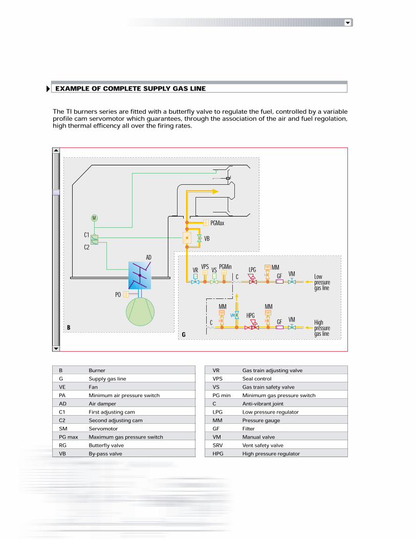
EXAMPLE OF COMPLETE SUPPLY GAS LINEThe TI burners series are fitted with a butterfly valve to regulate the fuel, controlled by a variableprofile cam servomotor which guarantees, through the association of the air and fuel regolation,high thermal efficency all over the firing rates.
BurnerSupply gas lineFanMinimum air pressure switchAir damperFirst adjusting camSecond adjusting camServomotorMaximum gas pressure switchButterfly valveBy-pass valve
BGVEPAADC1C2SMPG maxRGVB
Gas train adjusting valveSeal controlGas train safety valveMinimum gas pressure switchAnti-vibrant jointLow pressure regulatorPressure gaugeFilterManual valveVent safety valveHigh pressure regulator
VRVPSVSPG minCLPGMMGFVMSRVHPG
AD
PO
C2
MC1 VB
PGMax
B G
VR VPS VS PGMinC LPG MMGF VM Lowpressuregas line
C HPGMMGF VM Highpressuregas line
MM

Different lengths of the combustionhead can be chosen for the TI seriesof burners. The choice depends onthe thickness of the front panel andthe type of boiler.Depending on the type of generator, check that the penetration of thehead into the combustion chamber is correct.The TI burner series (except for TI 14 model), are provided with mobilehead combustion adjustable on the basis of required output, throughthe same servomotor used for the air damper regulation. This systemguarantees an optimal fuel/air mix all over the firing rates.
COMBUSTION HEAD
CHARACTERISTICS COMBUSTION HEAD CURVESGAS PRESSURE LOSSESThe following diagrams indicate the gas side losses of the combustion head and the regulatorbutterfly valve.Adding to the value of these losses the combustion chamber pressure and total gas train loss, it isobtained the minimal input pressure necessary to the gas train.
Example of TI 13 combustion head.
Butterfly valve losses
Combustion head losses
Pressure
drop
Reference conditions:Temperature: 15°CPressure: 1013.5 mbar
Reference conditions:Temperatura: 15°CPressione: 1013.5 mbar
mb
ar
10
40
20
30
50
kW
2800800 68004800
9000 11000
0
50003000 7000
8800 10800
1000
Mcal/h
G20∆P
Pressure
drop
60
70
12800
13000
TI 14
TI 1
0
TI 1
1
TI 1
2
TI 1
3
∆P
mb
ar
DN 100
DN 80
TI 10
TI 11
TI 12
TI 13
TI 14
2800800 68004800 8800 10800 Mcal/h 12800
kW9000 1100050003000 70001000 13000
G25
0
20
40
50
30
10
60
70
80
90
2
8
4
6
10
0
12
14
16 G25
0
20
10
G20
8
6
4
2
12
14
16
18

SETTING
The TI burner series can have “two stage progressive” or“modulating” setting.
On “modulating” setting,normally required in steamgenerators, in superheaterboilers or diathermic oil burners,a specific regulator and probesare required.T h e s e a r e s u p p l i e d a saccessories that must be orderedseparately.The burner can work for longperiods at intermediate outputlevels (figure B).
On “two stage progressive”setting, the burner graduallyadapts the output to therequested level, by varyingbetween two pre-set levels(figure A).
OUTPUT SETTING
Output
Control
led var
iable
Figure A
bar°C
MAX
MIN
time
time
“ Two stage progressive” setting
Output
Figure B
Control
led var
iable
AIR PRESSURE LOSSESm
ba
r
10
40
20
30
50
kW
0
Mcal/h
∆P
Pressure
drop
60
9000 1100050003000 70001000 13000 15000
2800800 68004800 8800 10800 12800
TI 14
TI 10
TI 11 TI
12
TI 13
bar°C
MAX
MIN
time
time
“ Modulating” setting
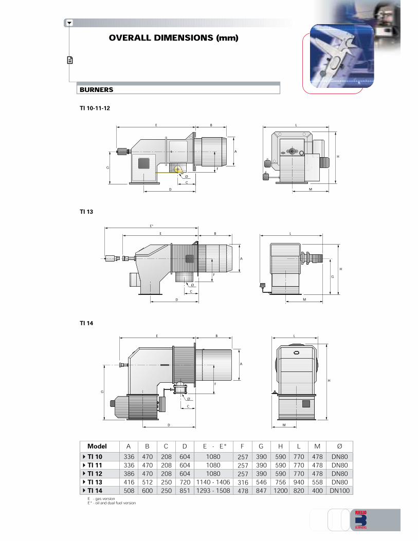
OVERALL DIMENSIONS (mm)
BURNERSTI 10-11-12
TI 13
TI 14
A
BE
CD
FGØ
Ø
A
BE
CD
F
E*
Ø
A
BE
C
D
FG
H
M
L
GH
M
L
H
M
L
Model A B DC HTI 10
TI 11
TI 12
TI 13
TI 14
470470470512600
336336386416508
5905905907561200
208208208250250
604604604720851
G390390390546847
FE - E*257257257316478
L770770770940820
M478478478558400
1080108010801140 - 14061293 - 1508
ØDN80DN80DN80DN80DN100
E - gas versionE* - oil and dual fuel version

MOUNTING FLANGE
X
ZY
TI 10-11-12
TI 13
TI 14
AIR CHANNEL FLANGE PERFORATION BOILERPLATE
AIR CHANNEL FLANGE
AIR CHANNEL FLANGE
PACKAGING
PERFORATION BOILERPLATE
PERFORATION BOILERPLATE45°
O
P
=
=
P
I
O
I
L
M
NP
O
CD
BA
EH F GQ
Q
G H
BA
E F
CD
DC
BA
EQG H F
Model
TI 10
TI 11
TI 12
TI 13
TI 14
X Y kg16801680168021002200
9609609601200940
Z93093093011501450
-----
320320320448620
Model A B DC HTI 10
TI 11
TI 12
TI 13
TI 14
300300300280452
368368368360542
280280280402562
240240240250410
340340340332510
G348348348480652
FE I240240260460-
L350350390--
220220220375390
M175175195--
O350350400430645
PM16M16M16M18M14
Q9991111
N120120130--

ACCESSORIES
High pressure flexible tubeTube code30942273094227309422730942263094226
1/2”1/2”1/2”3/4”3/4”
TubediameterTI 10TI 11TI 12TI 13TI 14
Burner
Nozzles type “ B3-30-AA” 30°
TI 10-11-12
Burner
High pressure flexible tubesIn order to facilitate the connection of the burnerto the fuel line adduction there are flexible tubesavailable according to the following table.
15001500150020002000
Tubelength (mm) 4040404040
Maximum workingpressure (bar)
Return nozzlesThe nozzles must be ordered separately. The following table shows the features and codes on thebasis of the maximum required fuel output.
Nozzles type “ B3-45-AA” 45°
150175200225250275300325350375400425450475500525550575600650700750800850900
Nozzle code3009626300962930096323009635300963830096413009644300964730096503009653300965630096593009662300966530096683009671300967430096773009680300968330096863009689300969230096953009698
Nozzle code3009625300962830096313009634300963730096403009643300964630096493009652300965530096583009661300966430096673009670300967330096763009679300968230096853009688300969130096943009697
Nominaloutput (kg/h)150175200225250275300325350375400425450475500525550575600650700750800850900
Nominaloutput (kg/h)
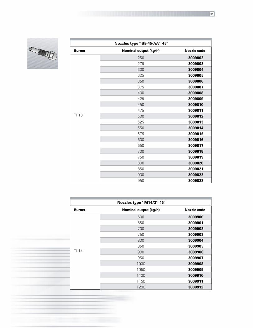
Nozzles type “ B5-45-AA” 45°
TI 13
Burner Nominal output (kg/h)250275300325350375400425450475500525550575600650700750800850900950
Nozzle code3009802300980330098043009805300980630098073009808300980930098103009811300981230098133009814300981530098163009817300981830098193009820300982130098223009823
Nozzles type “ M14/3” 45°
TI 14
Burner Nominal output (kg/h)600650700750800850900950
10001050110011501200
Nozzle code3009900300990130099023009903300990430099053009906300990730099083009909300991030099113009912

High pressure oil filterIn order to protect the hydraulic circuit of the burner from the possible presence of particles in thecombustion line, these following filters are available.
High pressure oil filter
TI 10TI 11TI 12TI 13TI 14
Burner
Circulation group (by-pass valve)If the burner is far away from the pumping group it is possible to install a circulation group that allowsthe circulates of the heated fuel during the stand-by phase.
Circulation Group (by-pass valve)
Group code
1/2”1/2”1/2”3/4”3/4”
Group diameter
TI 10TI 11TI 12TI 13TI 14
Burner
Check valveIn order to avoid fuel return, that could damage the hydraulic circuit, “check valve” are available.
Check valve
Valve code
1/2”1/2”1/2”3/4”3/4”
Valve diameter
TI 10TI 11TI 12TI 13TI 14
Burner
Potentiometer kitDepending on the servomotor fitted to the burner, a three-pole potentiometer (1000 Ω) can be installedto check the position of the servomotor. The KITS available for the various burners are listed below.
Potentiometer kit
Kit code
3010021TI 10-11-12-13-14Burner
1/2”1/2”1/2”3/4”3/4”
Filter diameter
500500500500500
Filtering degree (µ) Filter Code
In progressIn progressIn progressIn progressIn progress
In progressIn progressIn progressIn progressIn progress
In progressIn progressIn progressIn progressIn progress

A specific index guides your choice of burner fromthe various models available in the TI series.Follows a clear and detailed specification descriptionof the product.
Series : TI
SPECIFICATION
TIBASIC DESIGNATION
13 P/ M TC A-0 230/50-60EXTENDED DESIGNATION
Fuel : M Methane NM Heavy oil/MethaneG Light oil NAM Heavy oil steam atomising/MethaneN Heavy oil GM Light oil/MethaneNA Heavy oil steam atomising GP Light oil/LPGP LPG NAP Heavy oil steam atomising/LPGNP Heavy oil/LPGHead : TC Standard headTL Extended head
Air suction supply location : A-0 belowA-90 rightA-180 aboveA-270 leftFlame control system : FS1 Standard (1 stop every 24 h)FS2 Continuous working (1 stop every 72 h)
Auxiliary voltage :230/50-60 230V/50-60Hz110/50-60 110V/50-60Hz
DESIGNATION OF TI SERIES BURNERS
FS1
Size :10 - 11 - 12 - 13 - 14Setting : P/ progressive (modulating, mechanic cam)E/ electronic cam
Air suction temperature :T50 Room temperatureT150 Preheated at 150°CInstallation :I InternalO External
T50 I
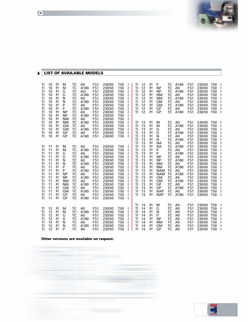
LIST OF AVAILABLE MODELSTI 10 P/ M TC A0 FS1 230/50 T50 ITI 10 P/ M TC A180 FS1 230/50 T50 ITI 10 P/ G TC AO FS1 230/50 T50 ITI 10 P/ G TC A180 FS1 230/50 T50 ITI 10 P/ N TC A0 FS1 230/50 T50 ITI 10 P/ N TC A180 FS1 230/50 T50 ITI 10 P/ P TC A0 FS1 230/50 T50 ITI 10 P/ P TC A180 FS1 230/50 T50 ITI 10 P/ NP TC A0 FS1 230/50 T50 ITI 10 P/ NP TC A180 FS1 230/50 T50 ITI 10 P/ NM TC A0 FS1 230/50 T50 ITI 10 P/ NM TC A180 FS1 230/50 T50 ITI 10 P/ GM TC A0 FS1 230/50 T50 ITI 10 P/ GM TC A180 FS1 230/50 T50 ITI 10 P/ GP TC A0 FS1 230/50 T50 ITI 10 P/ GP TC A180 FS1 230/50 T50 ITI 11 P/ M TC A0 FS1 230/50 T50 ITI 11 P/ M TC A180 FS1 230/50 T50 ITI 11 P/ G TC A0 FS1 230/50 T50 ITI 11 P/ G TC A180 FS1 230/50 T50 ITI 11 P/ N TC A0 FS1 230/50 T50 ITI 11 P/ N TC A180 FS1 230/50 T50 ITI 11 P/ P TC A0 FS1 230/50 T50 ITI 11 P/ P TC A180 FS1 230/50 T50 ITI 11 P/ NP TC A0 FS1 230/50 T50 ITI 11 P/ NP TC A180 FS1 230/50 T50 ITI 11 P/ NM TC A0 FS1 230/50 T50 ITI 11 P/ NM TC A180 FS1 230/50 T50 ITI 11 P/ GM TC A0 FS1 230/50 T50 ITI 11 P/ GM TC A180 FS1 230/50 T50 ITI 11 P/ GP TC A0 FS1 230/50 T50 ITI 11 P/ GP TC A180 FS1 230/50 T50 ITI 12 P/ M TC A0 FS1 230/50 T50 ITI 12 P/ M TC A180 FS1 230/50 T50 ITI 12 P/ G TC A0 FS1 230/50 T50 ITI 12 P/ G TC A180 FS1 230/50 T50 ITI 12 P/ N TC A0 FS1 230/50 T50 ITI 12 P/ N TC A180 FS1 230/50 T50 ITI 12 P/ P TC A0 FS1 230/50 T50 IOther versions are available on request.
TI 12 P/ P TC A180 FS1 230/50 T50 ITI 12 P/ NP TC A0 FS1 230/50 T50 ITI 12 P/ NP TC A180 FS1 230/50 T50 ITI 12 P/ NM TC A0 FS1 230/50 T50 ITI 12 P/ NM TC A180 FS1 230/50 T50 ITI 12 P/ GM TC A0 FS1 230/50 T50 ITI 12 P/ GM TC A180 FS1 230/50 T50 ITI 12 P/ GP TC A0 FS1 230/50 T50 ITI 12 P/ GP TC A180 FS1 230/50 T50 ITI 13 P/ M TC A0 FS1 230/50 T50 ITI 13 P/ M TC A180 FS1 230/50 T50 ITI 13 P/ G TC A0 FS1 230/50 T50 ITI 13 P/ G TC A180 FS1 230/50 T50 ITI 13 P/ N TC A0 FS1 230/50 T50 ITI 13 P/ N TC A180 FS1 230/50 T50 ITI 13 P/ NA TC A0 FS1 230/50 T50 ITI 13 P/ NA TC A180 FS1 230/50 T50 ITI 13 P/ P TC A0 FS1 230/50 T50 ITI 13 P/ P TC A180 FS1 230/50 T50 ITI 13 P/ NP TC A0 FS1 230/50 T50 ITI 13 P/ NP TC A180 FS1 230/50 T50 ITI 13 P/ NM TC A0 FS1 230/50 T50 ITI 13 P/ NM TC A180 FS1 230/50 T50 ITI 13 P/ NAM TC A0 FS1 230/50 T50 ITI 13 P/ NAM TC A180 FS1 230/50 T50 ITI 13 P/ GM TC A0 FS1 230/50 T50 ITI 13 P/ GM TC A180 FS1 230/50 T50 ITI 13 P/ GP TC A0 FS1 230/50 T50 ITI 13 P/ GP TC A180 FS1 230/50 T50 ITI 13 P/ NAP TC A0 FS1 230/50 T50 ITI 13 P/ NAP TC A180 FS1 230/50 T50 ITI 14 P/ M TC A0 FS1 230/50 T50 ITI 14 P/ G TC A0 FS1 230/50 T50 ITI 14 P/ N TC A0 FS1 230/50 T50 ITI 14 P/ P TC A0 FS1 230/50 T50 ITI 14 P/ NP TC A0 FS1 230/50 T50 ITI 14 P/ NM TC A0 FS1 230/50 T50 ITI 14 P/ GM TC A0 FS1 230/50 T50 ITI 14 P/ GP TC A0 FS1 230/50 T50 I
PRODUCT SPECIFICATIONSOIL BURNERCombustion head:Forced draught oil burner with two stage progressive or modulating setting, with separate supplies,fully automatic, made up of:- sheet-steel airlock painted with a cover for access to the internal elements- air damper for air setting with variable profile cam controlled by a servomotor- mobile combustion head (except for TI 14 model), that can be set on the basis of required output,fitted with:- stainless steel end cone, resistant to corrosion and high temperatures- ignition electrodes- pilot burner (TI13 - TI14 models)- flame stability disk- photocell for flame detection- minimum air pressure switch- nozzle pipe- safety nozzle valve- valves group with safety oil valves- automatic regulator of oil capacity controlled by a servomotor- maximum oil pressure switch on the return circuit- pressure gauge on the delivery circuit- pressure gauge on the return circuit- flame inspection window- shunt box with ignition transformer- IP 54 electric protection level.Reference directives and norms:- 89/336/EEC directive (electromagnetic compatibility)- 73/23/EEC directive (low voltage)- 98/37/EEC directive (machinery)- EN 267 (liquid fuel burners).Standard equipment:- screws for fixing the burner flange to the boiler- thermal screen- instruction handbook for installation, use and maintenance- spare parts catalogue.Available accessories to be ordered separately:- flexible tubes- return nozzles- high pressure oil filter- circulation group (by-pass valve)- check valve- potentiometer kit for the servomotor.
GAS BURNERCombustion Head:Forced draught gas burner with two stage progressive or modulating setting, withseparate supplies, fully automatic, made up of:- sheet-steel airlock painted with a cover for access to the internal elements- air damper for air setting with variable profile cam controlled by a servomotor- mobile combustion head (except for TI 14 model), that can be set on the basis of required output,fitted with:- stainless steel end cone, resistant to corrosion and high temperatures- ignition electrodes- pilot burner (TI13 - TI14 models)- ionisation probe- flame stability disk- minimum air pressure switch- maximum gas pressure switch- butterfly valve for the dosage of the fuel with a variable profile cam controlled by a servomotor- flame inspection window- gas pressure test point to the combustion head- shunt box with ignition transformer- IP 54 electric protection level.Reference directives and norms:- 89/336/EEC directive (electromagnetic compatibility)- 73/23/EEC directive (low voltage)- 90/396/EEC directive (gas)- EN 676 (gas burners).Standard equipment:- screws for fixing the burner flange to the boiler- thermal screen- screws for fixing the gas train flange to the burner- gas train gasket- instruction handbook for installation, use and maintenance- spare parts catalogue.Available accessories to be ordered separately:- potentiometer kit for the servomotor.
DUAL FUEL BURNER (OIL/GAS)Combustion Head:Forced draught dual fuel burner with two stage progressive or modulating setting, with separatesupplies, fully automatic, made up of:- sheet-steel airlock painted with a cover for access to the internal elements- air damper for air setting with variable profile cam controlled by a servomotor- mobile combustion head (except for TI 14 model), that can be set on the basis of required output,fitted with:- stainless steel end cone, resistant to corrosion and high temperatures- ignition electrodes- pilot burner (TI13-TI14 models)- flame stability disk- photocell for flame detection- nozzle pipe- safety nozzle valve- valves group with safety oil valves- automatic regulator of oil capacity controlled by a servomotor- maximum oil pressure switch on the return circuit- pressure gauge on the delivery circuit- pressure gauge on the return circuit- minimum air pressure switch- maximum gas pressure switch- butterfly valve for the dosage of the fuel with a variable profile cam controlled by a servomotor- flame inspection window- gas pressure test point to the combustion head- shunt box with ignition transformer- IP 54 electric protection level.Reference directives and norms:- 89/336/EEC directive (electromagnetic compatibility)- 73/23/EEC directive (low voltage)- 98/37/EEC directive (machinery)- 90/396/ECC directive (gas)- EN 267 (liquid fuel burners)- EN 676 (gas burners)Standard equipment:- screws for fixing the burner flange to the boiler- thermal screen- screws for fixing the gas train flange to the burner- gas train gasket- instruction handbook for installation, use and maintenance- spare parts catalogue.Available accessories to be ordered separately:- flexible tubes- return nozzles- high pressure oil filter- circulation group (by-pass valve)- check valve- potentiometer kit for the servomotor.

RIELLO S.p.A. - Via degli Alpini, 1 - 37045 LEGNAGO (VR) ItalyTel. ++39.0442630111 - Fax ++39.044221980Internet: http://www.rielloburners.com - E-mail: [email protected] 9001 Cert. n. 0061
Since the Company is constantly engaged in the production improvement, the aesthetic and dimensional features,the technical data, the equipment and the accessories can be changed.This document contains confidential and proprietary information of RIELLO S.p.A. Unless authorised, this informationshall not be divulged, nor duplicated in whole or in part.
Line
agra
fica
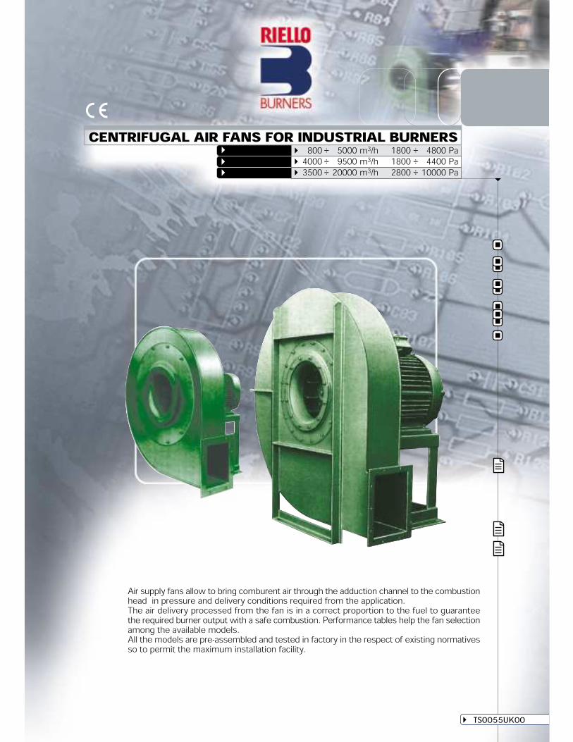
GCH SERIESCENTRIFUGAL AIR FANS FOR INDUSTRIAL BURNERS
TS0055UK00
800 ÷ 5000 m3/h 1800 ÷ 4800 Pa4000 ÷ 9500 m3/h 1800 ÷ 4400 Pa3500 ÷ 20000 m3/h 2800 ÷ 10000 Pa
Air supply fans allow to bring comburent air through the adduction channel to the combustionhead in pressure and delivery conditions required from the application.The air delivery processed from the fan is in a correct proportion to the fuel to guaranteethe required burner output with a safe combustion. Performance tables help the fan selectionamong the available models.All the models are pre-assembled and tested in factory in the respect of existing normativesso to permit the maximum installation facility.
GCM SERIESGBJ SERIES
GENERAL DESCRIPTION
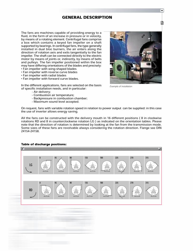
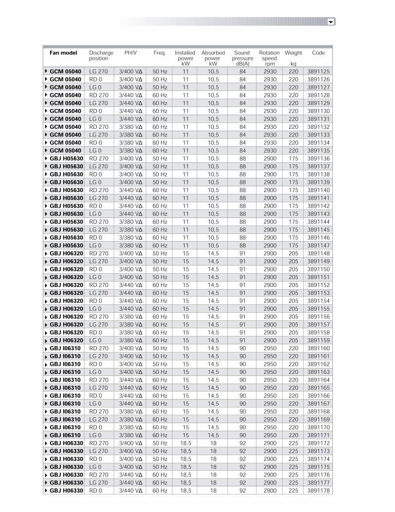
The fans are machines capable of providing energy to afluid, in the form of an increase in pressure or in velocity,by means of a rotating element. Centrifugal fans comprisea box which contains a keyed fan impeller on a shaftsupported by bearings. In centrifugal fans, the type generallyinstalled in dual bloc burners, the air enters along thedirection of rotation axis and exits tangentially to the fanimpeller. The shaft can be connected directly to the electricmotor by means of joints or, indirectly, by means of beltsand pulleys. The fan impeller positioned within the boxmay have differing orientations of the blades and precisely:• Fan impeller with wing-shaped blades• Fan impeller with reverse curve blades• Fan impeller with radial blades• Fan impeller with forward curve blades.In the different applications, fans are selected on the basisof specific installation needs, and in particular:- Air delivery;- Combustion air temperature;- Backpressure in combustion chamber;- Maximum sound level accepted.On request, fans with variable rotation speed in relation to power output can be supplied: in this casethe use of inverter allows energy saving.All the fans can be constructed with the delivery mouth in 16 different positions ( 8 in clockwiserotations RD and 8 in counterclockwise rotation LG ) as indicated on the orientation tables. Pleasenote that the direction of rotation is determined by looking at the fan from the transmission mode.Some sizes of these fans are revolvable always considering the rotation direction. Flange see DIN24154-24158.
Table of discharge positions:
Example of installation
270 31522518013590450LG
270 31522518013590450RD

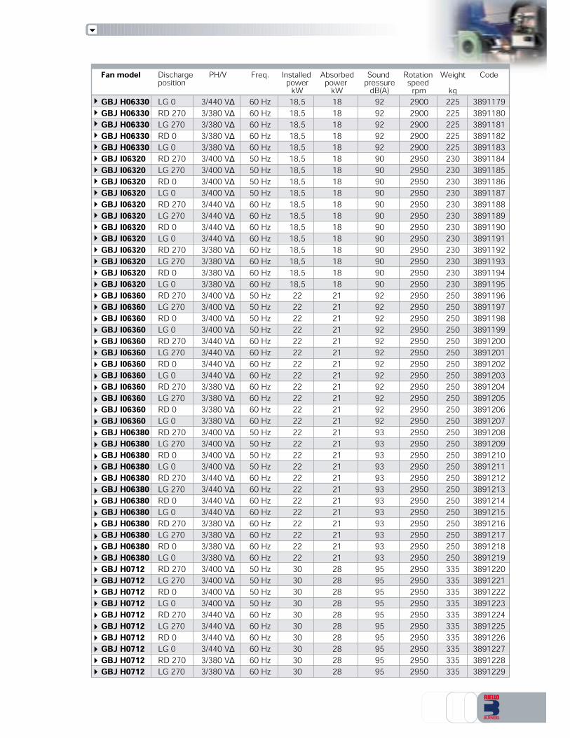
AVAILABLE MODELS
Fan model Discharge PH/V Freq. Installed Absorbed Sound Rotation Weight Codeposition power power pressure speedkW kW dB(A) rpm kgGCH 04020 RD 270 3/400 V∆ 50 Hz 1,5 1,4 72 2850 38 XXXGCH 04020 LG 270 3/400 V∆ 50 Hz 1,5 1,4 72 2850 38 XXXGCH 04020 RD 0 3/400 V∆ 50 Hz 1,5 1,4 72 2850 38 XXXGCH 04020 LG 0 3/400 V∆ 50 Hz 1,5 1,4 72 2850 38 XXXGCH 04020 RD 270 3/380 V∆ 60 Hz 1,5 1,4 72 2850 38 XXXGCH 04020 LG 270 3/380 V∆ 60 Hz 1,5 1,4 72 2850 38 XXXGCH 04020 RD 0 3/380 V∆ 60 Hz 1,5 1,4 72 2850 38 XXXGCH 04020 LG 0 3/380 V∆ 60 Hz 1,5 1,4 72 2850 38 XXXGCH 05020 RD 270 3/400 V∆ 50 Hz 5,5 5,2 78 2900 100 XXXGCH 05020 LG 270 3/400 V∆ 50 Hz 5,5 5,2 78 2900 100 XXXGCH 05020 RD 0 3/400 V∆ 50 Hz 5,5 5,2 78 2900 100 XXXGCH 05020 LG 0 3/400 V∆ 50 Hz 5,5 5,2 78 2900 100 XXXGCH 05020 RD 270 3/380 V∆ 60 Hz 5,5 5,2 78 2900 100 XXXGCH 05020 LG 270 3/380 V∆ 60 Hz 5,5 5,2 78 2900 100 XXXGCH 05020 RD 0 3/380 V∆ 60 Hz 5,5 5,2 78 2900 100 XXXGCH 05020 LG 0 3/380 V∆ 60 Hz 5,5 5,2 78 2900 100 XXXGCH 05040 RD 270 3/400 V∆ 50 Hz 7,5 7 80 2900 106 XXXGCH 05040 LG 270 3/400 V∆ 50 Hz 7,5 7 80 2900 106 XXXGCH 05040 RD 0 3/400 V∆ 50 Hz 7,5 7 80 2900 106 XXXGCH 05040 LG 0 3/400 V∆ 50 Hz 7,5 7 80 2900 106 XXXGCH 05040 RD 270 3/380 V∆ 60 Hz 7,5 7 80 2900 106 XXXGCH 05040 LG 270 3/380 V∆ 60 Hz 7,5 7 80 2900 106 XXXGCH 05040 RD 0 3/380 V∆ 60 Hz 7,5 7 80 2900 106 XXXGCH 05040 LG 0 3/380 V∆ 60 Hz 7,5 7 80 2900 106 XXXGCM 04540 RD 270 3/400 V∆ 50 Hz 7,5 7,1 82 2900 146 3891100GCM 04540 LG 270 3/400 V∆ 50 Hz 7,5 7,1 82 2900 146 3891101GCM 04540 RD 0 3/400 V∆ 50 Hz 7,5 7,1 82 2900 146 3891102GCM 04540 LG 0 3/400 V∆ 50 Hz 7,5 7,1 82 2900 146 3891103GCM 04540 RD 270 3/440 V∆ 60 Hz 7,5 7,1 82 2900 146 3891104GCM 04540 LG 270 3/440 V∆ 60 Hz 7,5 7,1 82 2900 146 3891105GCM 04540 RD 0 3/440 V∆ 60 Hz 7,5 7,1 82 2900 146 3891106GCM 04540 LG 0 3/440 V∆ 60 Hz 7,5 7,1 82 2900 146 3891107GCM 04540 RD 270 3/380 V∆ 60 Hz 7,5 7,1 82 2900 146 3891108GCM 04540 LG 270 3/380 V∆ 60 Hz 7,5 7,1 82 2900 146 3891109GCM 04540 RD 0 3/380 V∆ 60 Hz 7,5 7,1 82 2900 146 3891110GCM 04540 LG 0 3/380 V∆ 60 Hz 7,5 7,1 82 2900 146 3891111GCM 05020 RD 270 3/400 V∆ 50 Hz 9 8,7 83 2900 185 3891112GCM 05020 LG 270 3/400 V∆ 50 Hz 9 8,7 83 2900 185 3891113GCM 05020 RD 0 3/400 V∆ 50 Hz 9 8,7 83 2900 185 3891114GCM 05020 LG 0 3/400 V∆ 50 Hz 9 8,7 83 2900 185 3891115GCM 05020 RD 270 3/440 V∆ 60 Hz 9 8,7 83 2900 185 3891116GCM 05020 LG 270 3/440 V∆ 60 Hz 9 8,7 83 2900 185 3891117GCM 05020 RD 0 3/440 V∆ 60 Hz 9 8,7 83 2900 185 3891118GCM 05020 LG 0 3/440 V∆ 60 Hz 9 8,7 83 2900 185 3891119GCM 05020 RD 270 3/380 V∆ 60 Hz 9 8,7 83 2900 185 3891120GCM 05020 LG 270 3/380 V∆ 60 Hz 9 8,7 83 2900 185 3891121GCM 05020 RD 0 3/380 V∆ 60 Hz 9 8,7 83 2900 185 3891122GCM 05020 LG 0 3/380 V∆ 60 Hz 9 8,7 83 2900 185 3891123GCM 05040 RD 270 3/400 V∆ 50 Hz 11 10,5 84 2930 220 3891124
Fan model Discharge PH/V Freq. Installed Absorbed Sound Rotation Weight Codeposition power power pressure speedkW kW dB(A) rpm kgGCM 05040 LG 270 3/400 V∆ 50 Hz 11 10,5 84 2930 220 3891125GCM 05040 RD 0 3/400 V∆ 50 Hz 11 10,5 84 2930 220 3891126GCM 05040 LG 0 3/400 V∆ 50 Hz 11 10,5 84 2930 220 3891127GCM 05040 RD 270 3/440 V∆ 60 Hz 11 10,5 84 2930 220 3891128GCM 05040 LG 270 3/440 V∆ 60 Hz 11 10,5 84 2930 220 3891129GCM 05040 RD 0 3/440 V∆ 60 Hz 11 10,5 84 2930 220 3891130GCM 05040 LG 0 3/440 V∆ 60 Hz 11 10,5 84 2930 220 3891131GCM 05040 RD 270 3/380 V∆ 60 Hz 11 10,5 84 2930 220 3891132GCM 05040 LG 270 3/380 V∆ 60 Hz 11 10,5 84 2930 220 3891133GCM 05040 RD 0 3/380 V∆ 60 Hz 11 10,5 84 2930 220 3891134GCM 05040 LG 0 3/380 V∆ 60 Hz 11 10,5 84 2930 220 3891135GBJ H05630 RD 270 3/400 V∆ 50 Hz 11 10,5 88 2900 175 3891136GBJ H05630 LG 270 3/400 V∆ 50 Hz 11 10,5 88 2900 175 3891137GBJ H05630 RD 0 3/400 V∆ 50 Hz 11 10,5 88 2900 175 3891138GBJ H05630 LG 0 3/400 V∆ 50 Hz 11 10,5 88 2900 175 3891139GBJ H05630 RD 270 3/440 V∆ 60 Hz 11 10,5 88 2900 175 3891140GBJ H05630 LG 270 3/440 V∆ 60 Hz 11 10,5 88 2900 175 3891141GBJ H05630 RD 0 3/440 V∆ 60 Hz 11 10,5 88 2900 175 3891142GBJ H05630 LG 0 3/440 V∆ 60 Hz 11 10,5 88 2900 175 3891143GBJ H05630 RD 270 3/380 V∆ 60 Hz 11 10,5 88 2900 175 3891144GBJ H05630 LG 270 3/380 V∆ 60 Hz 11 10,5 88 2900 175 3891145GBJ H05630 RD 0 3/380 V∆ 60 Hz 11 10,5 88 2900 175 3891146GBJ H05630 LG 0 3/380 V∆ 60 Hz 11 10,5 88 2900 175 3891147GBJ H06320 RD 270 3/400 V∆ 50 Hz 15 14,5 91 2900 205 3891148GBJ H06320 LG 270 3/400 V∆ 50 Hz 15 14,5 91 2900 205 3891149GBJ H06320 RD 0 3/400 V∆ 50 Hz 15 14,5 91 2900 205 3891150GBJ H06320 LG 0 3/400 V∆ 50 Hz 15 14,5 91 2900 205 3891151GBJ H06320 RD 270 3/440 V∆ 60 Hz 15 14,5 91 2900 205 3891152GBJ H06320 LG 270 3/440 V∆ 60 Hz 15 14,5 91 2900 205 3891153GBJ H06320 RD 0 3/440 V∆ 60 Hz 15 14,5 91 2900 205 3891154GBJ H06320 LG 0 3/440 V∆ 60 Hz 15 14,5 91 2900 205 3891155GBJ H06320 RD 270 3/380 V∆ 60 Hz 15 14,5 91 2900 205 3891156GBJ H06320 LG 270 3/380 V∆ 60 Hz 15 14,5 91 2900 205 3891157GBJ H06320 RD 0 3/380 V∆ 60 Hz 15 14,5 91 2900 205 3891158GBJ H06320 LG 0 3/380 V∆ 60 Hz 15 14,5 91 2900 205 3891159GBJ I06310 RD 270 3/400 V∆ 50 Hz 15 14,5 90 2950 220 3891160GBJ I06310 LG 270 3/400 V∆ 50 Hz 15 14,5 90 2950 220 3891161GBJ I06310 RD 0 3/400 V∆ 50 Hz 15 14,5 90 2950 220 3891162GBJ I06310 LG 0 3/400 V∆ 50 Hz 15 14,5 90 2950 220 3891163GBJ I06310 RD 270 3/440 V∆ 60 Hz 15 14,5 90 2950 220 3891164GBJ I06310 LG 270 3/440 V∆ 60 Hz 15 14,5 90 2950 220 3891165GBJ I06310 RD 0 3/440 V∆ 60 Hz 15 14,5 90 2950 220 3891166GBJ I06310 LG 0 3/440 V∆ 60 Hz 15 14,5 90 2950 220 3891167GBJ I06310 RD 270 3/380 V∆ 60 Hz 15 14,5 90 2950 220 3891168GBJ I06310 LG 270 3/380 V∆ 60 Hz 15 14,5 90 2950 220 3891169GBJ I06310 RD 0 3/380 V∆ 60 Hz 15 14,5 90 2950 220 3891170GBJ I06310 LG 0 3/380 V∆ 60 Hz 15 14,5 90 2950 220 3891171GBJ H06330 RD 270 3/400 V∆ 50 Hz 18,5 18 92 2900 225 3891172GBJ H06330 LG 270 3/400 V∆ 50 Hz 18,5 18 92 2900 225 3891173GBJ H06330 RD 0 3/400 V∆ 50 Hz 18,5 18 92 2900 225 3891174GBJ H06330 LG 0 3/400 V∆ 50 Hz 18,5 18 92 2900 225 3891175GBJ H06330 RD 270 3/440 V∆ 60 Hz 18,5 18 92 2900 225 3891176GBJ H06330 LG 270 3/440 V∆ 60 Hz 18,5 18 92 2900 225 3891177GBJ H06330 RD 0 3/440 V∆ 60 Hz 18,5 18 92 2900 225 3891178
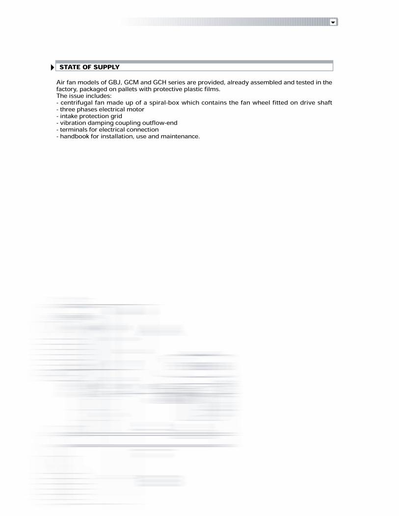
Fan model Discharge PH/V Freq. Installed Absorbed Sound Rotation Weight Codeposition power power pressure speedkW kW dB(A) rpm kgGBJ H06330 LG 0 3/440 V∆ 60 Hz 18,5 18 92 2900 225 3891179GBJ H06330 RD 270 3/380 V∆ 60 Hz 18,5 18 92 2900 225 3891180GBJ H06330 LG 270 3/380 V∆ 60 Hz 18,5 18 92 2900 225 3891181GBJ H06330 RD 0 3/380 V∆ 60 Hz 18,5 18 92 2900 225 3891182GBJ H06330 LG 0 3/380 V∆ 60 Hz 18,5 18 92 2900 225 3891183GBJ I06320 RD 270 3/400 V∆ 50 Hz 18,5 18 90 2950 230 3891184GBJ I06320 LG 270 3/400 V∆ 50 Hz 18,5 18 90 2950 230 3891185GBJ I06320 RD 0 3/400 V∆ 50 Hz 18,5 18 90 2950 230 3891186GBJ I06320 LG 0 3/400 V∆ 50 Hz 18,5 18 90 2950 230 3891187GBJ I06320 RD 270 3/440 V∆ 60 Hz 18,5 18 90 2950 230 3891188GBJ I06320 LG 270 3/440 V∆ 60 Hz 18,5 18 90 2950 230 3891189GBJ I06320 RD 0 3/440 V∆ 60 Hz 18,5 18 90 2950 230 3891190GBJ I06320 LG 0 3/440 V∆ 60 Hz 18,5 18 90 2950 230 3891191GBJ I06320 RD 270 3/380 V∆ 60 Hz 18,5 18 90 2950 230 3891192GBJ I06320 LG 270 3/380 V∆ 60 Hz 18,5 18 90 2950 230 3891193GBJ I06320 RD 0 3/380 V∆ 60 Hz 18,5 18 90 2950 230 3891194GBJ I06320 LG 0 3/380 V∆ 60 Hz 18,5 18 90 2950 230 3891195GBJ I06360 RD 270 3/400 V∆ 50 Hz 22 21 92 2950 250 3891196GBJ I06360 LG 270 3/400 V∆ 50 Hz 22 21 92 2950 250 3891197GBJ I06360 RD 0 3/400 V∆ 50 Hz 22 21 92 2950 250 3891198GBJ I06360 LG 0 3/400 V∆ 50 Hz 22 21 92 2950 250 3891199GBJ I06360 RD 270 3/440 V∆ 60 Hz 22 21 92 2950 250 3891200GBJ I06360 LG 270 3/440 V∆ 60 Hz 22 21 92 2950 250 3891201GBJ I06360 RD 0 3/440 V∆ 60 Hz 22 21 92 2950 250 3891202GBJ I06360 LG 0 3/440 V∆ 60 Hz 22 21 92 2950 250 3891203GBJ I06360 RD 270 3/380 V∆ 60 Hz 22 21 92 2950 250 3891204GBJ I06360 LG 270 3/380 V∆ 60 Hz 22 21 92 2950 250 3891205GBJ I06360 RD 0 3/380 V∆ 60 Hz 22 21 92 2950 250 3891206GBJ I06360 LG 0 3/380 V∆ 60 Hz 22 21 92 2950 250 3891207GBJ H06380 RD 270 3/400 V∆ 50 Hz 22 21 93 2950 250 3891208GBJ H06380 LG 270 3/400 V∆ 50 Hz 22 21 93 2950 250 3891209GBJ H06380 RD 0 3/400 V∆ 50 Hz 22 21 93 2950 250 3891210GBJ H06380 LG 0 3/400 V∆ 50 Hz 22 21 93 2950 250 3891211GBJ H06380 RD 270 3/440 V∆ 60 Hz 22 21 93 2950 250 3891212GBJ H06380 LG 270 3/440 V∆ 60 Hz 22 21 93 2950 250 3891213GBJ H06380 RD 0 3/440 V∆ 60 Hz 22 21 93 2950 250 3891214GBJ H06380 LG 0 3/440 V∆ 60 Hz 22 21 93 2950 250 3891215GBJ H06380 RD 270 3/380 V∆ 60 Hz 22 21 93 2950 250 3891216GBJ H06380 LG 270 3/380 V∆ 60 Hz 22 21 93 2950 250 3891217GBJ H06380 RD 0 3/380 V∆ 60 Hz 22 21 93 2950 250 3891218GBJ H06380 LG 0 3/380 V∆ 60 Hz 22 21 93 2950 250 3891219GBJ H0712 RD 270 3/400 V∆ 50 Hz 30 28 95 2950 335 3891220GBJ H0712 LG 270 3/400 V∆ 50 Hz 30 28 95 2950 335 3891221GBJ H0712 RD 0 3/400 V∆ 50 Hz 30 28 95 2950 335 3891222GBJ H0712 LG 0 3/400 V∆ 50 Hz 30 28 95 2950 335 3891223GBJ H0712 RD 270 3/440 V∆ 60 Hz 30 28 95 2950 335 3891224GBJ H0712 LG 270 3/440 V∆ 60 Hz 30 28 95 2950 335 3891225GBJ H0712 RD 0 3/440 V∆ 60 Hz 30 28 95 2950 335 3891226GBJ H0712 LG 0 3/440 V∆ 60 Hz 30 28 95 2950 335 3891227GBJ H0712 RD 270 3/380 V∆ 60 Hz 30 28 95 2950 335 3891228GBJ H0712 LG 270 3/380 V∆ 60 Hz 30 28 95 2950 335 3891229

Fan model Discharge PH/V Freq. Installed Absorbed Sound Rotation Weight Codeposition power power pressure speedkW kW dB(A) rpm kgGBJ H0712 RD 0 3/380 V∆ 60 Hz 30 28 95 2950 335 3891230GBJ H0712 LG 0 3/380 V∆ 60 Hz 30 28 95 2950 335 3891231GBJ H0717 RD 270 3/400 VD 50 Hz 37 35 95 2950 350 3891232GBJ H0717 LG 270 3/400 V∆ 50 Hz 37 35 95 2950 350 3891233GBJ H0717 RD 0 3/400 V∆ 50 Hz 37 35 95 2950 350 3891234GBJ H0717 LG 0 3/400 V∆ 50 Hz 37 35 95 2950 350 3891235GBJ H0717 RD 270 3/440 V∆ 60 Hz 37 35 95 2950 350 3891236GBJ H0717 LG 270 3/440 V∆ 60 Hz 37 35 95 2950 350 3891237GBJ H0717 RD 0 3/440 V∆ 60 Hz 37 35 95 2950 350 3891238GBJ H0717 LG 0 3/440 V∆ 60 Hz 37 35 95 2950 350 3891239GBJ H0717 RD 270 3/380 V∆ 60 Hz 37 35 95 2950 350 3891240GBJ H0717 LG 270 3/380 V∆ 60 Hz 37 35 95 2950 350 3891241GBJ H0717 RD 0 3/380 V∆ 60 Hz 37 35 95 2950 350 3891242GBJ H0717 LG 0 3/380 V∆ 60 Hz 37 35 95 2950 350 3891243GBJ I0710 RD 270 3/400 V∆ 50 Hz 37 35 94 2950 400 3891244GBJ I0710 LG 270 3/400 V∆ 50 Hz 37 35 94 2950 400 3891245GBJ I0710 RD 0 3/400 V∆ 50 Hz 37 35 94 2950 400 3891246GBJ I0710 LG 0 3/400 V∆ 50 Hz 37 35 94 2950 400 3891247GBJ I0710 RD 270 3/440 V∆ 60 Hz 37 35 94 2950 400 3891248GBJ I0710 LG 270 3/440 V∆ 60 Hz 37 35 94 2950 400 3891249GBJ I0710 RD 0 3/440 V∆ 60 Hz 37 35 94 2950 400 3891250GBJ I0710 LG 0 3/440 V∆ 60 Hz 37 35 94 2950 400 3891251GBJ I0710 RD 270 3/380 V∆ 60 Hz 37 35 94 2950 400 3891252GBJ I0710 LG 270 3/380 V∆ 60 Hz 37 35 94 2950 400 3891253GBJ I0710 RD 0 3/380 V∆ 60 Hz 37 35 94 2950 400 3891254GBJ I0710 LG 0 3/380 V∆ 60 Hz 37 35 94 2950 400 3891255GBJ I0712 RD 270 3/400 V∆ 50 Hz 45 42 94 2950 310 3891256GBJ I0712 LG 270 3/400 V∆ 50 Hz 45 42 94 2950 310 3891257GBJ I0712 RD 0 3/400 V∆ 50 Hz 45 42 94 2950 310 3891258GBJ I0712 LG 0 3/400 V∆ 50 Hz 45 42 94 2950 310 3891259GBJ I0712 RD 270 3/440 V∆ 60 Hz 45 42 94 2950 310 3891260GBJ I0712 LG 270 3/440 V∆ 60 Hz 45 42 94 2950 310 3891261GBJ I0712 RD 0 3/440 V∆ 60 Hz 45 42 94 2950 310 3891262GBJ I0712 LG 0 3/440 V∆ 60 Hz 45 42 94 2950 310 3891263GBJ I0712* RD 270 3/380 V∆ 60 Hz 45 42 94 2950 310 3891264GBJ I0712* LG 270 3/380 V∆ 60 Hz 45 42 94 2950 310 3891265GBJ I0712* RD 0 3/380 V∆ 60 Hz 45 42 94 2950 310 3891266GBJ I0712* LG 0 3/380 V∆ 60 Hz 45 42 94 2950 310 3891267GBJ I0800A RD 270 3/400 V∆ 50 Hz 55 50 95 2950 340 3891268GBJ I0800A LG 270 3/400 V∆ 50 Hz 55 50 95 2950 340 3891269GBJ I0800A RD 0 3/400 V∆ 50 Hz 55 50 95 2950 340 3891270GBJ I0800A LG 0 3/400 V∆ 50 Hz 55 50 95 2950 340 3891271GBJ I0800A RD 270 3/440 V∆ 60 Hz 55 50 95 2950 340 3891272GBJ I0800A LG 270 3/440 V∆ 60 Hz 55 50 95 2950 340 3891273GBJ I0800A RD 0 3/440 V∆ 60 Hz 55 50 95 2950 340 3891274GBJ I0800A LG 0 3/440 V∆ 60 Hz 55 50 95 2950 340 3891275GBJ I0800A* RD 270 3/380 V∆ 60 Hz 55 50 95 2950 340 3891276GBJ I0800A* LG 270 3/380 V∆ 60 Hz 55 50 95 2950 340 3891277GBJ I0800A* RD 0 3/380 V∆ 60 Hz 55 50 95 2950 340 3891278GBJ I0800A* LG 0 3/380 V∆ 60 Hz 55 50 95 2950 340 3891279* Motor size 45-55 kW voltage supply 3/380 V/60 Hz are rewinded. Other electrical supply are available on request.Noise level tolerance: + 3 dB

TECHNICAL DATADELIVERY AND STATIC PRESSURE
Static pressure (mmH2O)
Airdeliveryin m3/min10141822252831354045505663718090100112125140160180200225250280315355
Airdeliveryin m3/s0,20,20,30,40,40,50,50,60,70,80,80,91,11,21,31,51,71,92,12,32,73,03,33,84,24,75,35,9
Fanmodel 04020 05020GCH
05040 04540GCM GBJ
05020 05040 H05630 H06320 I06310 H06330 I06320 I06360 H06380 H0712 H0717 I0710 I0712 I0800A
277268254228209188162
452449447443433418396373341
489487483473463451433396
348341329311287258222176132
380373361344326298263213165
433427419396368338293250180
583568547525500455411344277
642641626606583554
656632608587551
642641626606583554518470
656632608587551522464399332
727703672646612569514457363
691681666648619583525466383
842826807764709652568
942926907864809752658562427
942926907864809752
898883855825785735684592493356
10281012995956916862789
The features listed are referred to air at the temperature of +15°C and at the barometrical pressure of 760 mmHg with specificgravity 1,226 kg/m3Capacity tolerance: ± 5 %

OVERALL DIMENSIONS (mm)
GCH SERIES
eg
df
a cb g
N° 8 bores
Fan and basement
Outlet flange
Model A B DC HGCH 04020GCH 05020GCH 05040
580735735660800800
678585400570570
230290290
G375450450
FE80100100
I215320320
M245360360
L270392392
N137250250
P182525
O604545
280355355
Model a b dcGCH 04020GCH 05020GCH 05040
219265265180224224
250294294125160160
g112112112
fe195230230
167200200
I
L M
NO P
N°4 bores
BE
A
DG
C
H
F

GCM SERIES
Fan and basement
Outlet flange
Model A B DC HGCM 04540GCM 05020GCM 05040
75084084093010101010
132148148720750820
328365365
G560630630
FE140160160
I320320425
M360360400
L392392440
N250250340
P252530
O454555
335355355
Model a b dcGCM 04540GCM 05020GCM 05040
405448448355400400
435480480250280280
g125125125
fe330360360
300332332N° 14 bores eg
df
a cb g
g
g
g
G
C
H
FB
E
AD
I
L M
NO P
N°4 bores

GBJ SERIES
Model a b dcGBJ H05630GBJ H06320GBJ H06330GBJ H06380GBJ H0712GBJ H0717GBJ I06310GBJ I06320GBJ I06360GBJ I0710GBJ I0712GBJ I0800A
332366366366405405405405405448448497
280315315315355355355355355400400450
260395395395435435435435435480480530
200224224224250250250250250280280315
g125125125125125125125125125125125125
fe280304304304330330330330330360360395
249273273273300300300300300332332366
Model A B DC HGBJ H05630GBJ H06320GBJ H06330GBJ H06380GBJ H0712GBJ H0717GBJ I06310GBJ I06320GBJ I06360GBJ I0710GBJ I0712GBJ I0800A
82593093093010001000930930930100010001120
90010001000100011201120100010001000112011201250
110120120120135135135135135150150170
6807007507758258258208208201000710750
310342342342382382322322322360360405
G500560560560630630560560560630630710
FE120135135135145145145145145160160180
I425425425470500500425425470550320320
M360400400450510510400400450565360392
L440440440500570570440440500626392320
N250340340340385385340340370425250360
P303030354040303535402525
O455555557575555565854545
400425425425475475425425425475475530
eg
df
a cb gg
N°10 bores
Fan and basement
Outlet flange
G
C
H
FB
E
A
D
I
L M
NO P
N°4 bores

ACCESSORIES
Fan silencers for GCM and GBJ modelsCylindrical silencers in zinc sheet full of circular flange for mounting on the fansaspiration mouths.
Fan silencers for GCM models
GXS B32GXS B35GXS B35
Suctionflange Lenght(m)111
Noise reduction(dBA)3-43-43-4
GCM 04540GCM 05020GCM 05040
FanmodelsGWA 0321LGWA 0361LGWA 0361L
Outletflange
Fan silencers for GBJ models
GXS B28GXS B32GXS B32GXS B32GXS B35GXS B35GXS B35GXS B35GXS B35GXS B41GXS B41GXS B50
Suctionflange Lenght(m)111111111111
Noise reduction(dBA)3-43-43-43-43-43-43-43-43-43-43-43-4
GBJ H05630GBJ H06320GBJ H06330GBJ H06380GBJ H0712GBJ H0717GBJ I06310GBJ I06320GBJ I06360GBJ I0710GBJ I0712GBJ I0800A
FanmodelsGWA 0286LGWA 0321LGWA 0321LGWA 0321LGWA 0361LGWA 0361LGWA 0361LGWA 0361LGWA 0361LGWA 0405LGWA 0405LGWA 0506P
Outletflange
GXS A 1032GXS A 1035GXS A 1035
Silencer
GXS A 1028GXS A 1032GXS A 1032GXS A 1032GXS A 1035GXS A 1035GXS A 1035GXS A 1035GXS A 1035GXS A 1040 PGXS A 1040 PGXS A 1050
Silencer

Sound proofing boxUsed to dampen the fan noise during operation. In the standard version they are provided with:- vibration-damping joints between the fan panels and the suction and delivery flanges- flexible supports between the fan and the base- silenced circulation air intakes- lifting eyebolts- self-bearing chassis- removable inspection panels.
Circular DAPO’ flow regulators for GCM and GBJ modelsFlow rate regulators are used to vary the fan flow rate, so as to keep the efficiency high even duringthe operation. Available with manual and motor-driven operation.
Circular DAPO’ flow regulators for GCM modelsWeight (kg)
192121
GCM 04540GCM 05020GCM 05040
Fan models
Circular DAPO’ flow regulators for GBJ modelsWeight (kg)
171919192121212121232326
GBJ H05630GBJ H06320GBJ H06330GBJ H06380GBJ H0712GBJ H0717GBJ I06310GBJ I06320GBJ I06360GBJ I0710GBJ I0712
GBJ I0800A
Fan models
GXH _0315GXH _0355GXH _0355
Type
GXH _0280GXH _0315GXH _0315GXH _0315GXH _0355GXH _0355GXH _0355GXH _0355GXH _0355GXH _0400GXH _0400GXH _0450
Type
888
Bores n°
888888888121212
Bores n°
For all the fan models it is possible to predispose electrical motor for the application of inverter so to have variablefan rotation speed by varying frequency.
Sound proofing boxGBJ H05630GBJ H06320GBJ H06330GBJ H06380GBJ I06310GBJ I06320GBJ I06360GBJ H0712GBJ H0717GBJ I0710GBJ I0712
GBJ I0800A
Fan modelsGXB 5HGXB 6HGXB 6HGXB 6HGXB 6IGXB 6IGXB 6IGXB 7HGXB 7HGB 7IGB 7IGXB 8I
Type1150x1110x11201250x1250x12201250x1250x12201250x1250x12201250x1250x12201250x1250x12201250x1250x12201320x1250x13401320x1250x13401320x1430x13401320x1430x13401440x1500x1470
Dimensions (mm) Noise reduction10-15 dB(A) at 2 m10-15 dB(A) at 2 m10-15 dB(A) at 2 m10-15 dB(A) at 2 m10-15 dB(A) at 2 m10-15 dB(A) at 2 m10-15 dB(A) at 2 m10-15 dB(A) at 2 m10-15 dB(A) at 2 m10-15 dB(A) at 2 m10-15 dB(A) at 2 m10-15 dB(A) at 2 m

Series : GCH, GCM, GBJ
PRODUCT SPECIFICATIONS
GBJBASIC DESIGNATION
H05630 LG 0 3Ph / 380 V∆ / 50 HzEXTENDED DESIGNATION
Electrical supply : 3Ph / 380 V∆ / 60 HzPh / 400 V∆ / 50 Hz3Ph / 440 V∆ / 60 Hz3Ph / 220 V∆ / 60 Hz3Ph / 230 V∆ / 50 Hz
Motor certification : CEEEX PROOFRINA (Naval approval)...
DESIGNATION OF AIR FANS MODELS
Model 04020 ........................................................................ I0800ADischarge position : RD 0 45 90 135 180 225 270 315LG 0 45 90 135 180 225 270 315
I CE
Installation : I IndoorO Outdoor
Air fan models of GBJ, GCM and GCH series are provided, already assembled and tested in thefactory, packaged on pallets with protective plastic films.The issue includes:- centrifugal fan made up of a spiral-box which contains the fan wheel fitted on drive shaft- three phases electrical motor- intake protection grid- vibration damping coupling outflow-end- terminals for electrical connection- handbook for installation, use and maintenance.
STATE OF SUPPLY


RIELLO S.p.A. - Via degli Alpini, 1 - 37045 LEGNAGO (VR) ItalyTel. ++39.0442630111 - Fax ++39.044221980Internet: http://www.rielloburners.com - E-mail: [email protected] 9001 Cert. n. 0061
Since the Company is constantly engaged in the production improvement, the aesthetic anddimensional features, the technical data, the equipment and the accessories can be changed.This document contains confidential and proprietary information of RIELLO S.p.A.Unless authorised, this information shall not be divulged, nor duplicated in whole or in part.
Line
agra
fica
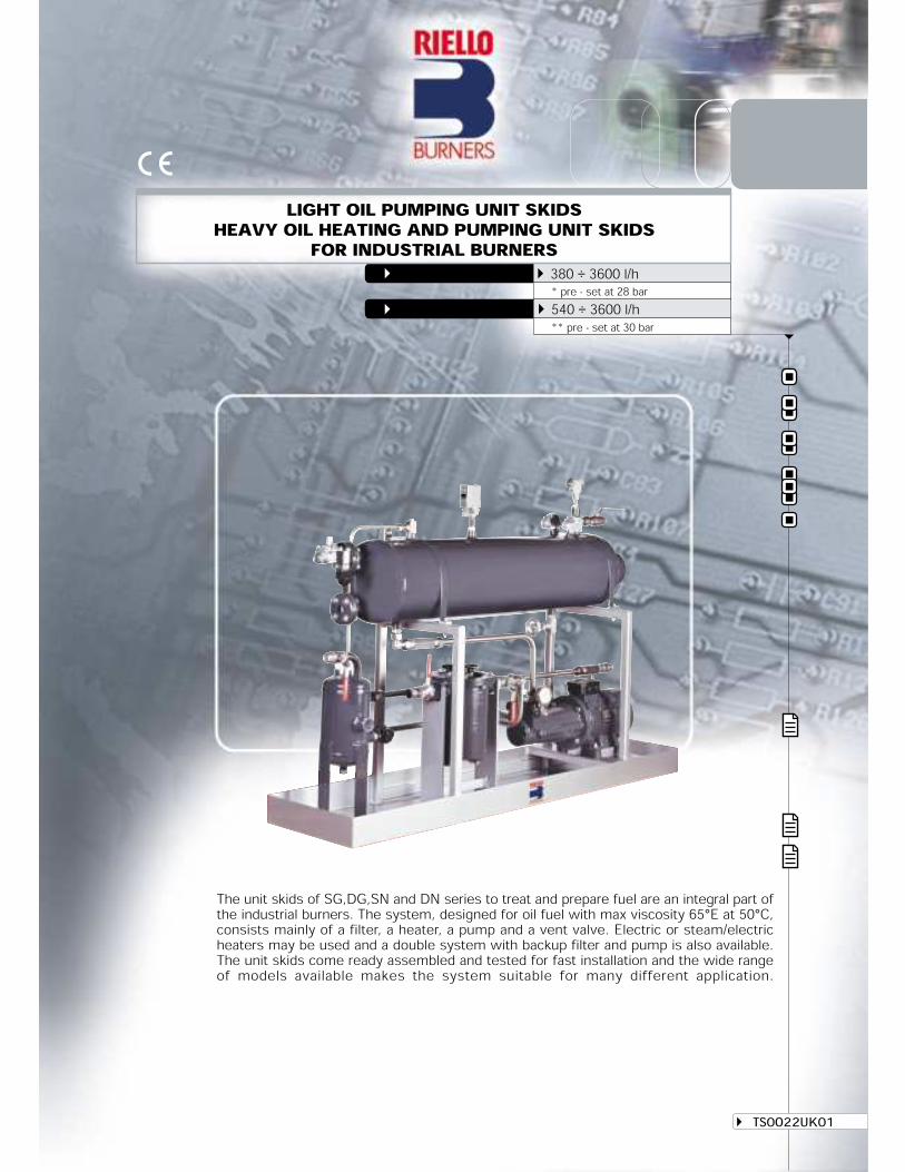
The unit skids of SG,DG,SN and DN series to treat and prepare fuel are an integral part ofthe industrial burners. The system, designed for oil fuel with max viscosity 65°E at 50°C,consists mainly of a filter, a heater, a pump and a vent valve. Electric or steam/electricheaters may be used and a double system with backup filter and pump is also available.The unit skids come ready assembled and tested for fast installation and the wide rangeof models available makes the system suitable for many different application.
TS0O22UK01
LIGHT OIL PUMPING UNIT SKIDSHEAVY OIL HEATING AND PUMPING UNIT SKIDSFOR INDUSTRIAL BURNERSSG and DG SERIES* 380 ÷ 3600 l/hSN and DN SERIES** 540 ÷ 3600 l/h
** pre - set at 30 bar * pre - set at 28 bar

GENERAL DESCRIPTIONHYDRAULIC LAY-OUTTECHNICAL DESCRIPTIONTECHNICAL DATAOVERALL DIMENSIONSLIST OF AVAILABLE MODELSSTATE OF SUPPLY
GENERAL DESCRIPTIONHYDRAULIC LAY-OUTTECHNICAL DESCRIPTIONTECHNICAL DATAOVERALL DIMENSIONSLIST OF AVAILABLE MODELSSTATE OF SUPPLY
DESIGNATION OF SERIES
AVAILABLE ACCESSORIES
INDEX OF CONTENTS
LIGHT OIL PUMPING UNIT SKIDS
Since the Company is constantly engaged in the production improvement, the aesthetic and dimensional features,the technical data, the equipment and the accessories can be changed.This document contains confidential and proprietary information of RIELLO S.p.A. Unless authorised, this informationshall not be divulged, nor duplicated in whole or in part.
The following index, divided in sections, allows search of interest arguments inside the presentbrochure.
HEAVY OIL HEATING AND PUMPING UNIT SKIDS
ACCESSORIES
SPECIFICATION
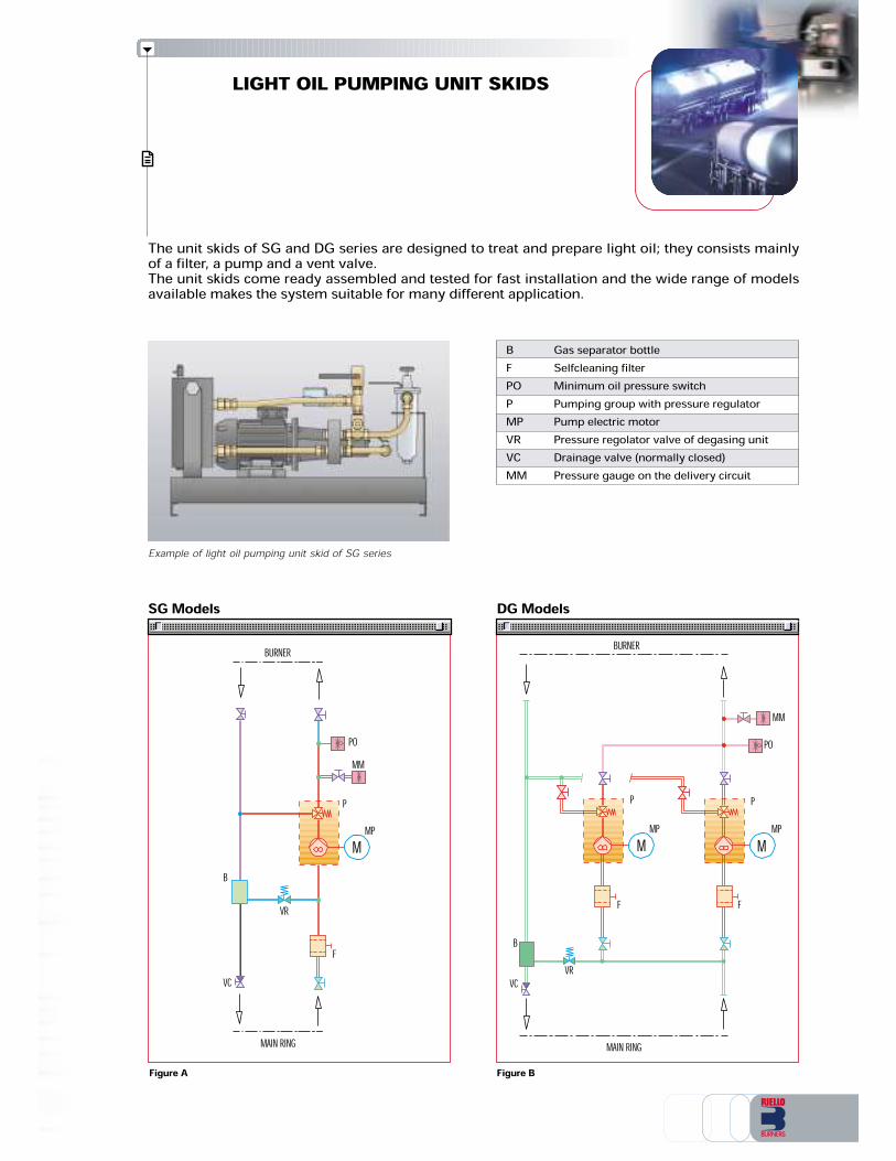
BFPOPMPVRVCMM
Gas separator bottleSelfcleaning filterMinimum oil pressure switchPumping group with pressure regulatorPump electric motorPressure regolator valve of degasing unitDrainage valve (normally closed)Pressure gauge on the delivery circuit
LIGHT OIL PUMPING UNIT SKIDS
The unit skids of SG and DG series are designed to treat and prepare light oil; they consists mainlyof a filter, a pump and a vent valve.The unit skids come ready assembled and tested for fast installation and the wide range of modelsavailable makes the system suitable for many different application.
SG Models DG Models
Figure A Figure B
BURNER
PMP
F F
MPP
MMPO
VRVCB
MAIN RING
M M
Example of light oil pumping unit skid of SG series
MM
VR
VC
MAIN RING
PO
B
F
PMPM
BURNER
LIGHT OIL PUMPING UNIT SKIDS - TECHNICAL DATA
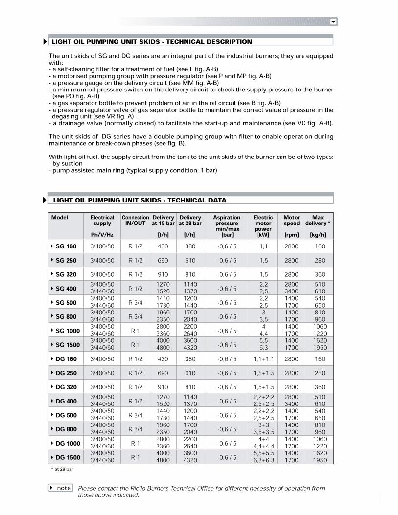
SG 160 3/400/50 R 1/2 430 380 -0,6 / 5 1,1 2800 160SG 250 3/400/50 R 1/2 690 610 -0,6 / 5 1,5 2800 280SG 320 3/400/50 R 1/2 910 810 -0,6 / 5 1,5 2800 360SG 400 3/400/50 R 1/2 1270 1140 -0,6 / 5 2,2 2800 5103/440/60 1520 1370 2,5 3400 610SG 500 3/400/50 R 3/4 1440 1200 -0,6 / 5 2,2 1400 5403/440/60 1730 1440 2,5 1700 650SG 800 3/400/50 R 3/4 1960 1700 -0,6 / 5 3 1400 810 3/440/60 2350 2040 3,5 1700 960SG 1000 3/400/50 R 1 2800 2200 -0,6 / 5 4 1400 10603/440/60 3360 2640 4,4 1700 1220SG 1500 3/400/50 R 1 4000 3600 -0,6 / 5 5,5 1400 16203/440/60 4800 4320 6,3 1700 1950DG 160 3/400/50 R 1/2 430 380 -0,6 / 5 1,1+1,1 2800 160DG 250 3/400/50 R 1/2 690 610 -0,6 / 5 1,5+1,5 2800 280DG 320 3/400/50 R 1/2 910 810 -0,6 / 5 1,5+1,5 2800 360DG 400 3/400/50 R 1/2 1270 1140 -0,6 / 5 2,2+2,2 2800 5103/440/60 1520 1370 2,5+2,5 3400 610DG 500 3/400/50 R 3/4 1440 1200 -0,6 / 5 2,2+2,2 1400 540 3/440/60 1730 1440 2,5+2,5 1700 650DG 800 3/400/50 R 3/4 1960 1700 -0,6 / 5 3+3 1400 810 3/440/60 2350 2040 3,5+3,5 1700 960DG 1000 3/400/50 R 1 2800 2200 -0,6 / 5 4+4 1400 10603/440/60 3360 2640 4,4+4,4 1700 1220DG 1500 3/400/50 R 1 4000 3600 -0,6 / 5 5,5+5,5 1400 16203/440/60 4800 4320 6,3+6,3 1700 1950
Model Electrical Connection Delivery Delivery Aspiration Electric Motor Maxsupply IN/OUT at 15 bar at 28 bar pressure motor speed delivery *min/max powerPh/V/Hz [l/h] [l/h] [bar] [kW] [rpm] [kg/h]
* at 28 bar
LIGHT OIL PUMPING UNIT SKIDS - TECHNICAL DESCRIPTIONThe unit skids of SG and DG series are an integral part of the industrial burners; they are equippedwith:- a self-cleaning filter for a treatment of fuel (see F fig. A-B)- a motorised pumping group with pressure regulator (see P and MP fig. A-B)- a pressure gauge on the delivery circuit (see MM fig. A-B)- a minimum oil pressure switch on the delivery circuit to check the supply pressure to the burner(see PO fig. A-B)- a gas separator bottle to prevent problem of air in the oil circuit (see B fig. A-B)- a pressure regulator valve of gas separator bottle to maintain the correct value of pressure in thedegasing unit (see VR fig. A)- a drainage valve (normally closed) to facilitate the start-up and maintenance (see VC fig. A-B).The unit skids of DG series have a double pumping group with filter to enable operation duringmaintenance or break-down phases (see fig. B).With light oil fuel, the supply circuit from the tank to the unit skids of the burner can be of two types:- by suction- pump assisted main ring (typical supply condition: 1 bar)
Please contact the Riello Burners Technical Office for different necessity of operation fromthose above indicated.note
OVERALL DIMENSIONS (mm)
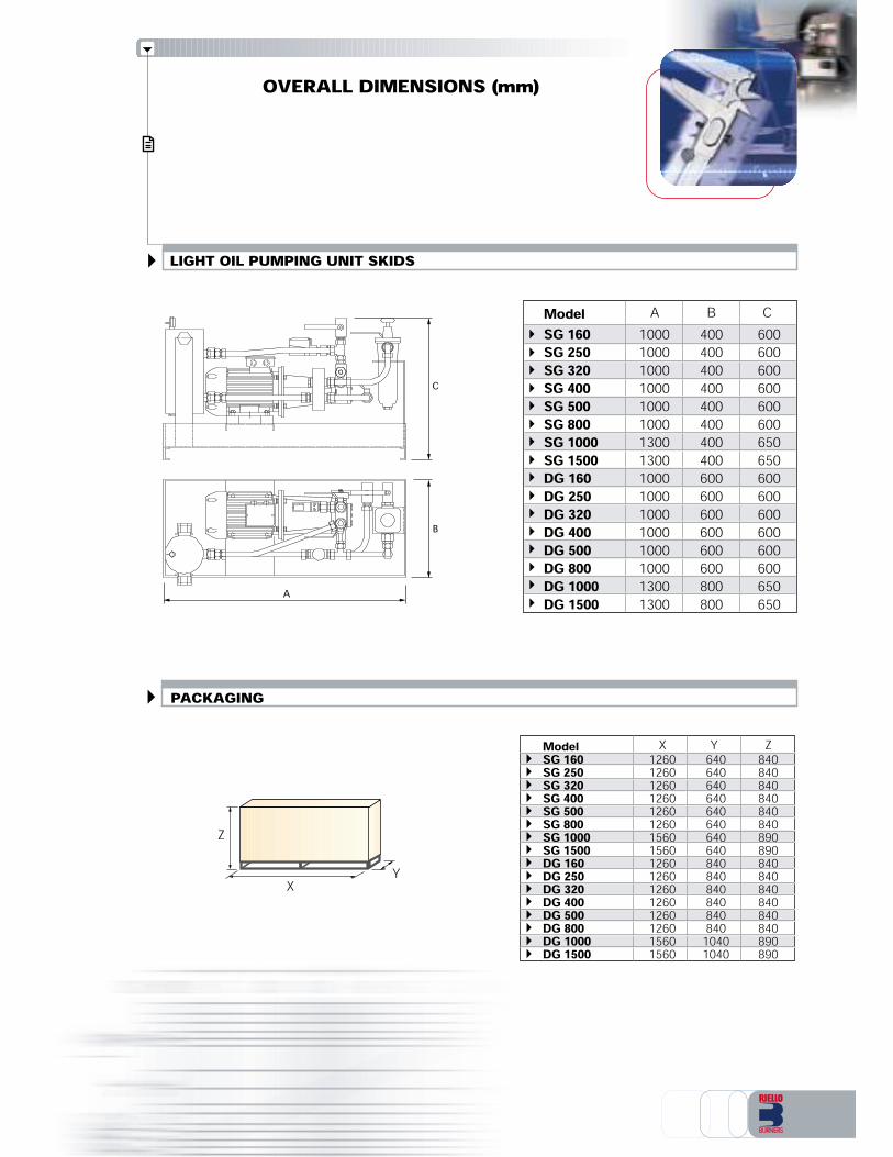
LIGHT OIL PUMPING UNIT SKIDS
ModelSG 160 1000 400 600SG 250 1000 400 600SG 320 1000 400 600SG 400 1000 400 600SG 500 1000 400 600SG 800 1000 400 600SG 1000 1300 400 650SG 1500 1300 400 650DG 160 1000 600 600DG 250 1000 600 600DG 320 1000 600 600DG 400 1000 600 600DG 500 1000 600 600DG 800 1000 600 600DG 1000 1300 800 650DG 1500 1300 800 650
X
ZY
PACKAGING
A B C
ModelSG 160 1260 640 840SG 250 1260 640 840SG 320 1260 640 840SG 400 1260 640 840SG 500 1260 640 840SG 800 1260 640 840SG 1000 1560 640 890SG 1500 1560 640 890DG 160 1260 840 840DG 250 1260 840 840DG 320 1260 840 840DG 400 1260 840 840DG 500 1260 840 840DG 800 1260 840 840DG 1000 1560 1040 890DG 1500 1560 1040 890
X Y Z
C
B
A

LIGHT OIL PUMPING UNIT SKIDS - LIST OF AVAILABLE MODELSSingle pumping unitSG 160 SB 3/400/50 230/50-60SG 250 SB 3/400/50 230/50-60SG 320 SB 3/400/50 230/50-60SG 400 SB 3/400/50-3/440/60 230/50-60SG 500 SB 3/400/50-3/440/60 230/50-60SG 800 SB 3/400/50-3/440/60 230/50-60SG 1000 SB 3/400/50-3/440/60 230/50-60SG 1500 SB 3/400/50-3/440/60 230/50-60Other versions are available on request.
Pumping unit skids supplied, in function of model, for filtering and to pressurize light oil, made upof:- Base in painted steel sheet- Manual shut off valve on the output circuit- Self-cleaning filter (double on the D version)- Gas separator group- Pressure regulator valve of gas separator bottle- Pumping group with pressure regulator (double on the D version)- Pressure gauge- Minimum oil pressure switch- Drainage valve- Shunt box.Available accessories to be ordered separately:- Pumping unit for main ring- Automatic gas separator- Line filter- Pressure regulator.(See accessories section).
Double pumping unitDG 160 SB 3/400/50 230/50-60DG 250 SB 3/400/50 230/50-60DG 320 SB 3/400/50 230/50-60DG 400 SB 3/400/50-3/440/60 230/50-60DG 500 SB 3/400/50-3/440/60 230/50-60DG 800 SB 3/400/50-3/440/60 230/50-60DG 1000 SB 3/400/50-3/440/60 230/50-60DG 1500 SB 3/400/50-3/440/60 230/50-60
LIGHT OIL PUMPING UNIT SKIDS - STATE OF SUPPLY

BFPORSPMPPSTMTmVRVCVVMMTPVS
Gas separator bottleSelfcleaning filterMinimum oil pressure switchHeating cartridgePumping group with pressure regulatorPump electric motorHeavy oil heaterMaximum thermostatMinimum thermostatPressure regolator valve of degasing unitDrainage valve (normally closed)Steam circuit solenoid valvePressure gauge on the delivery circuitTemperature probeSafety valve
HEAVY OIL HEATING ANDPUMPING UNIT SKIDS
The unit skids of SN-EP, DN-EP, SN-EV and DN-EV series are designedto treat and prepare heavy oil with max viscosity 65°E at 50°C; theyconsists mainly of a filter, a heater, a pump and a vent valve.The heater can be Electrical or Electrical/Steam type.The unit skids come ready assembled and tested for fast installation and the wide range of modelsavailable makes the system suitable for many different application.
Figure C Figure D
RS
MMP
MPMRS
MMP
MPM
RS FRS F
RSB
DN EP Models
RS
MM
RS F
RSB
SN EP Models
VR
VCMAIN RING
BURNER
TPPOTMTm
PS
VR
VC
MAIN RING
BURNER
TPPOTMTm
PS
PMPM
Example of heavy oil Heating and Pumping unit skid of SN-EV series

RS
MMP
MPMRS
MMP
MPM
RS FRS F
RSB VR
VC
MAIN RING
BURNER
TPPOTMTm
PS
VVVS
DN EV Models
RS
MM
RS F
RSB
SN EV Models
Figure E Figure F
VR
VC
MAIN RING
BURNER
TPPOTMTm
PS
VVVS
PMPM
HEAVY OIL HEATING AND PUMPING UNIT SKIDS - TECHNICAL DESCRIPTIONThe unit skids of SN-EP, DN-EP, SN-EV and DN-EV series are an integral part of the industrialburners; they are equipped with:- a self-cleaning filter, heated by electrical resistance, for a treatment of fuel (see F fig. C-D-E-F)- a motorised pumping group with pressure regulator, heated by electrical resistance (see P andMP fig. C-D-E-F)- a pressure gauge on the delivery circuit (see MM fig. C-D-E-F)- an electrical or electrical/steam heavy oil heaters (see PS fig. C-D-E-F)- a minimum and a maximum thermostat to check the oil supply temperature to the burner (seeTm and TM fig. C-D-E-F)- a minimum oil pressure switch on the delivery circuit to check the oil supply pressure to theburner (see PO fig. C-D-E-F)- a temperature probe for the electronic control (see TP fig. C-D-E-F)- a gas separator bottle, heated by electrical resistance, to prevent problem of air in the oil circuit(see B fig C-D-E-F)- a pressure regulator valve of gas separator bottle to maintain the correct value of pressure in thedegasing unit (see VR fig. C-D-E-F)- a drainage valve (normally closed) to facilitate the start-up and maintenance (see VC fig. C-D-E-F).The electrical/steam heaters of SN-EV and DN-EV series are furthermore equipped with:- a steam circuit solenoid valve to allow steam passage trough the heater- a safety valveAn electronic control device on the basis of required heat, regulates steam circuit solenoid valveopening and electrical resistances energising to maintain heavy oil temperature at the correct value.The unit skids of DN-EP and DN-EV series have a double pumping group with filter and pressuregauge to enable operation during maintenance or break-down phases (see fig. D-F).With heavy oil fuel, the supply circuit from the tank to the unit skids of the burner is a pump assistedmain ring (typical supply condition: 1,5 bar – 60°C)
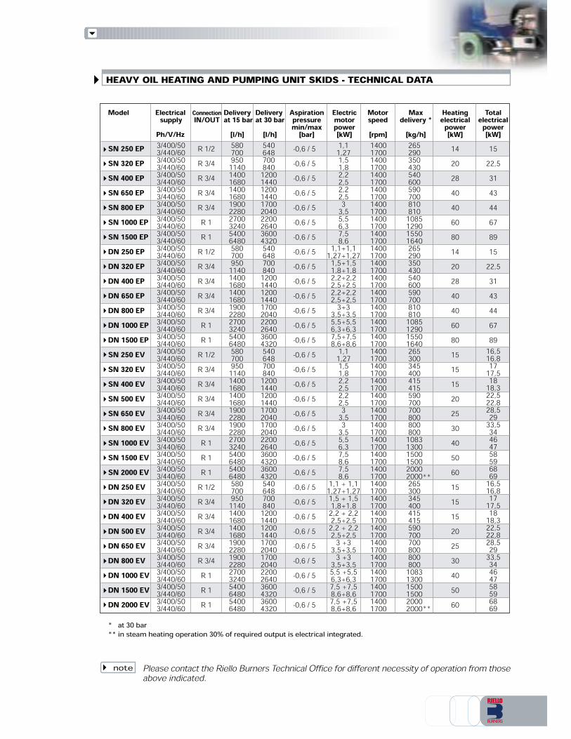
* at 30 bar** in steam heating operation 30% of required output is electrical integrated.
Please contact the Riello Burners Technical Office for different necessity of operation from thoseabove indicated.note
540648700840120014401200144017002040220026403600432054064870084012001440120014401700204022002640360043205406487008401200144012001440170020401700204022002640360043203600432054064870084012001440120014401700204017002040220026403600432036004320
26529035043054060059070081081010851290155016402652903504305406005907008108101085129015501640265300345400415415590700700800800800108313001500150020002000265300345400415415590700700800800800108313001500150020002000
1420284040608014202840406080151515202530405060151515202530405060
1522,5314344678915
22,53143446789
5807009501140140016801400168019002280270032405400648058070095011401400168014001680190022802700324054006480580700950114014001680140016801900228019002280270032405400648054006480580700950114014001680140016801900228019002280270032405400648054006480
-0,6 / 5-0,6 / 5-0,6 / 5-0,6 / 5-0,6 / 5-0,6 / 5-0,6 / 5-0,6 / 5-0,6 / 5-0,6 / 5-0,6 / 5-0,6 / 5-0,6 / 5-0,6 / 5-0,6 / 5-0,6 / 5-0,6 / 5-0,6 / 5-0,6 / 5-0,6 / 5-0,6 / 5-0,6 / 5-0,6 / 5-0,6 / 5-0,6 / 5-0,6 / 5-0,6 / 5-0,6 / 5-0,6 / 5-0,6 / 5-0,6 / 5-0,6 / 5
1,11,271,51,82,22,52,22,533,55,56,37,58,61,1+1,11,27+1,271,5+1,51,8+1,82,2+2,22,5+2,52,2+2,22,5+2,53+33,5+3,55,5+5,56,3+6,37,5+7,58,6+8,61,11,271,51,82,22,52,22,533,533,55,56,37,58,67,58,61,1 + 1,11,27+1,271,5 + 1,51,8+1,82,2 + 2,22,5+2,52,2 + 2,22,5+2,53 +33,5+3,53 +33,5+3,55,5 +5,56,3+6,37,5 +7,58,6+8,67,5 +7,58,6+8,6
1400170014001700140017001400170014001700140017001400170014001700140017001400170014001700140017001400170014001700140017001400170014001700140017001400170014001700140017001400170014001700140017001400170014001700140017001400170014001700140017001400170014001700
3/400/503/440/603/400/503/440/603/400/503/440/603/400/503/440/603/400/503/440/603/400/503/440/603/400/503/440/603/400/503/440/603/400/503/440/603/400/503/440/603/400/503/440/603/400/503/440/603/400/503/440/603/400/503/440/603/400/503/440/603/400/503/440/603/400/503/440/603/400/503/440/603/400/503/440/603/400/503/440/603/400/503/440/603/400/503/440/603/400/503/440/603/400/503/440/603/400/503/440/603/400/503/440/603/400/503/440/603/400/503/440/603/400/503/440/603/400/503/440/603/400/503/440/603/400/503/440/60
16,516,81717,51818,322,522,828,52933,53446475859686916,516,81717,51818,322,522,828,52933,534464758596869
R 1/2R 3/4R 3/4R 3/4R 3/4R 1R 1
R 1/2R 3/4R 3/4R 3/4R 3/4R 1R 1
R 1/2R 3/4R 3/4R 3/4R 3/4R 3/4R 1R 1R 1
R 1/2R 3/4R 3/4R 3/4R 3/4R 3/4R 1R 1R 1
Delivery at 30 bar [l/h]
Maxdelivery *[kg/h]
Heatingelectricalpower[kW]Totalelectricalpower[kW]
Model Delivery at 15 bar[l/h]
Aspirationpressuremin/max[bar]Electricmotorpower[kW]
Motorspeed [rpm]
ElectricalsupplyPh/V/Hz
ConnectionIN/OUT
HEAVY OIL HEATING AND PUMPING UNIT SKIDS - TECHNICAL DATA
SN 250 EPSN 320 EPSN 400 EPSN 650 EPSN 800 EPSN 1000 EPSN 1500 EPDN 250 EPDN 320 EPDN 400 EPDN 650 EPDN 800 EPDN 1000 EPDN 1500 EPSN 250 EVSN 320 EVSN 400 EVSN 500 EVSN 650 EVSN 800 EVSN 1000 EVSN 1500 EVSN 2000 EVDN 250 EVDN 320 EVDN 400 EVDN 500 EVDN 650 EVDN 800 EVDN 1000 EVDN 1500 EVDN 2000 EV
**
**

ModelSN 250 EV 1700 400 1105SN 320 EV 1700 400 1200SN 400 EV 1700 400 1200SN 500 EV 1700 400 1200SN 650 EV 1700 400 1200SN 800 EV 1700 400 1200SN 1000 EV 1900 600 1300SN 1500 EV 1900 600 1300SN 2000 EV 1900 600 1300DN 250 EV 1700 700 1105DN 320 EV 1700 700 1200DN 400 EV 1700 700 1200DN 500 EV 1700 700 1200DN 650 EV 1700 700 1200DN 800 EV 1700 700 1200DN 1000 EV 1900 900 1300DN 1500 EV 1900 900 1300DN 2000 EV 1900 900 1300
OVERALL DIMENSIONS (mm)
HEAVY OIL HEATING AND PUMPING UNIT SKIDS
ModelSN 250 EP 1400 400 985SN 320 EP 1400 400 985SN 400 EP 1500 400 1100SN 500 EP 1500 400 1100SN 650 EP 1500 400 1100SN 800 EP 1500 600 1100SN 1000 EP 1500 600 1100SN 1500 EP 1500 600 1100DN 250 EP 1400 700 985DN 320 EP 1400 700 985DN 400 EP 1500 700 1100DN 500 EP 1500 700 1100DN 650 EP 1500 700 1100DN 800 EP 1500 900 1100DN 1000 EP 1500 900 1100DN 1500 EP 1500 900 1100
Electrical heater
C
B
A B C
A B C
C
B
Electrical/steam heater
A
A
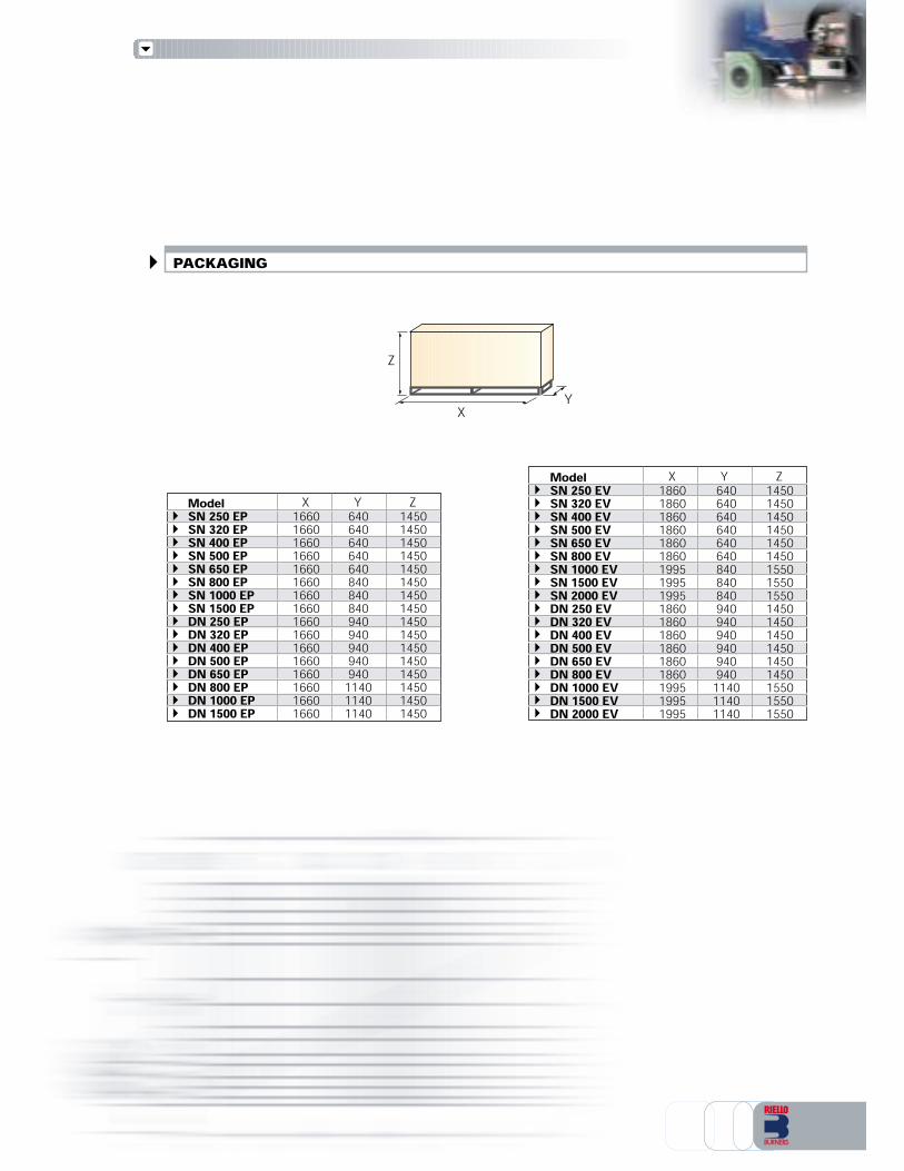
X
ZY
PACKAGING
ModelSN 250 EV 1860 640 1450SN 320 EV 1860 640 1450SN 400 EV 1860 640 1450SN 500 EV 1860 640 1450SN 650 EV 1860 640 1450SN 800 EV 1860 640 1450SN 1000 EV 1995 840 1550SN 1500 EV 1995 840 1550SN 2000 EV 1995 840 1550DN 250 EV 1860 940 1450DN 320 EV 1860 940 1450DN 400 EV 1860 940 1450DN 500 EV 1860 940 1450DN 650 EV 1860 940 1450DN 800 EV 1860 940 1450DN 1000 EV 1995 1140 1550DN 1500 EV 1995 1140 1550DN 2000 EV 1995 1140 1550
ModelSN 250 EP 1660 640 1450SN 320 EP 1660 640 1450SN 400 EP 1660 640 1450SN 500 EP 1660 640 1450SN 650 EP 1660 640 1450SN 800 EP 1660 840 1450SN 1000 EP 1660 840 1450SN 1500 EP 1660 840 1450DN 250 EP 1660 940 1450DN 320 EP 1660 940 1450DN 400 EP 1660 940 1450DN 500 EP 1660 940 1450DN 650 EP 1660 940 1450DN 800 EP 1660 1140 1450DN 1000 EP 1660 1140 1450DN 1500 EP 1660 1140 1450
X Y ZX Y Z

HEAVY OIL HEATING AND PUMPING UNIT SKIDS - LIST OF AVAILABLE MODELSElectrical heaterSingle pumping unitSN 250 EP SB 3/400/50-3/440/60 230/50-60SN 320 EP SB 3/400/50-3/440/60 230/50-60SN 400 EP SB 3/400/50-3/440/60 230/50-60SN 650 EP SB 3/400/50-3/440/60 230/50-60SN 800 EP SB 3/400/50-3/440/60 230/50-60SN 1000 EP SB 3/400/50-3/440/60 230/50-60SN 1500 EP SB 3/400/50-3/440/60 230/50-60Electrical/Steam heaterSingle pumping unitSN 250 EV SB 3/400/50-3/440/60 230/50-60SN 320 EV SB 3/400/50-3/440/60 230/50-60SN 400 EV SB 3/400/50-3/440/60 230/50-60SN 500 EV SB 3/400/50-3/440/60 230/50-60SN 650 EV SB 3/400/50-3/440/60 230/50-60SN 800 EV SB 3/400/50-3/440/60 230/50-60SN 1000 EV SB 3/400/50-3/440/60 230/50-60SN 1500 EV SB 3/400/50-3/440/60 230/50-60SN 2000 EV SB 3/400/50-3/440/60 230/50-60Other versions are available on request.
Heating and pumping unit skids supplied, in function of model, for filtering, heating and to pressurizeheavy oil, made up of:- Base in painted steel sheet- Manual shut off valve on the output circuit- Self-cleaning filter (double on the D version)- Gas separator group- Pressure regulator valve of gas separator bottle- Pumping group with pressure regulator (double on the D version)- Pressure gauge- Electrical heater (on the EP models)- Mixed heating: electrical/steam (on the EV models)- Minimum oil pressure switch- Maximum thermostat- Minimum thermostat- Shunt box- Steam circuit solenoid valve- Temperature probe- Safety valve- Heating cartridge- Drainage valve.Available accessories to be ordered separately:- Pumping unit for main ring- Automatic gas separator- Heating cartridge- Line filter- Pressure regulator.(See accessories section).
HEAVY OIL HEATING AND PUMPING UNIT SKIDS - STATE OF SUPPLY
Double pumping unitDN 250 EP SB 3/400/50-3/440/60 230/50-60DN 320 EP SB 3/400/50-3/440/60 230/50-60DN 400 EP SB 3/400/50-3/440/60 230/50-60DN 650 EP SB 3/400/50-3/440/60 230/50-60DN 800 EP SB 3/400/50-3/440/60 230/50-60DN 1000 EP SB 3/400/50-3/440/60 230/50-60DN 1500 EP SB 3/400/50-3/440/60 230/50-60
Double pumping unitDN 250 EV SB 3/400/50-3/440/60 230/50-60DN 320 EV SB 3/400/50-3/440/60 230/50-60DN 400 EV SB 3/400/50-3/440/60 230/50-60DN 500 EV SB 3/400/50-3/440/60 230/50-60DN 650 EV SB 3/400/50-3/440/60 230/50-60DN 800 EV SB 3/400/50-3/440/60 230/50-60DN 1000 EV SB 3/400/50-3/440/60 230/50-60DN 1500 EV SB 3/400/50-3/440/60 230/50-60DN 2000 EV SB 3/400/50-3/440/60 230/50-60
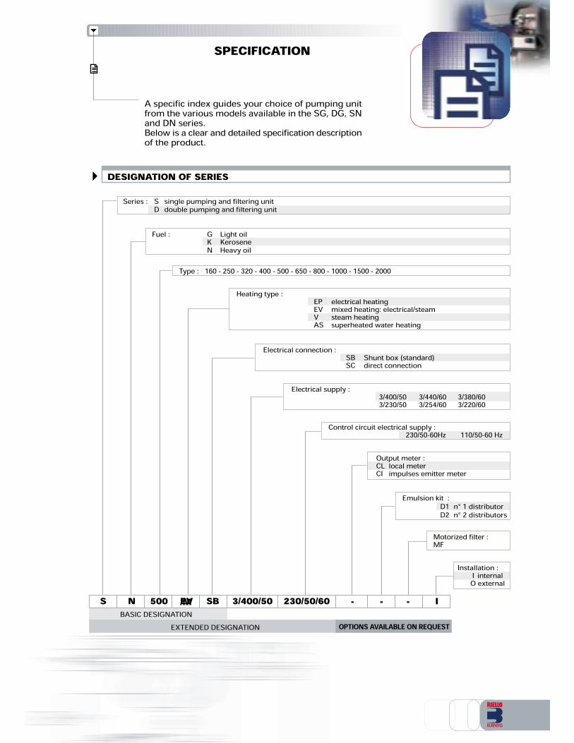
SPECIFICATION
Type : 160 - 250 - 320 - 400 - 500 - 650 - 800 - 1000 - 1500 - 2000
Fuel : G Light oilK KeroseneN Heavy oil
Motorized filter :MF
SBASIC DESIGNATION
N 500 /M 3/400/50 230/50/60EXTENDED DESIGNATION
Heating type : EP electrical heatingEV mixed heating: electrical/steamV steam heatingAS superheated water heatingElectrical connection : SB Shunt box (standard)SC direct connection
Electrical supply : 3/400/50 3/440/60 3/380/603/230/50 3/254/60 3/220/60Control circuit electrical supply : 230/50-60Hz 110/50-60 Hz
SB
Series : S single pumping and filtering unitD double pumping and filtering unit
Output meter :CL local meterCI impulses emitter meter
EV
Installation : I internalO external
OPTIONS AVAILABLE ON REQUEST- --
Emulsion kit :D1 n° 1 distributorD2 n° 2 distributors
A specific index guides your choice of pumping unitfrom the various models available in the SG, DG, SNand DN series.Below is a clear and detailed specification descriptionof the product.
DESIGNATION OF SERIES
I

Pumping unit for main ring
ACCESSORIES
HC 100HC 160HC 280
100160280
Electrical power [W]Type Code309062030906213090622
Model
Max viscosity 65° E at 50°C
Max viscosity 12° E at 50°CCode
3093220309322130932223093223309322430932253093226
RG 600RG 1000RG 1500RG 2000RG 3000RG 4500RG 6000
RGS 670RGS 1000RGS 1330RGS 2000RGS 3000RGS 4000
In progress30932273093228309322930932303093231
Motor speed[rpm]14001700140017001400170014001700140017001400170014001700950110095011009501100950110095011009501100
Electric motorpower [kW]0,370,430,550,650,750,881,11,271,51,82,22,533,50,750,881,11,271,51,82,22,533,544,8
Outputat 9 bar [l/h]6007201000120015001800200024003000360045005400600072006708001000120013301600200024003000360040004800
ConnectionIN/OUTRp 1/2Rp 3/4Rp 3/4Rp 3/4Rp 1Rp 1Rp 1
Rp 1Rp 1Rp 1Rp 1 1/4Rp 1 1/4Rp 1 1/4
Electrical supplyPh/V/Hz3/400/503/440/603/400/503/440/603/400/503/440/603/400/503/440/603/400/503/440/603/400/503/440/603/400/503/440/603/400/503/440/603/400/503/440/603/400/503/440/603/400/503/440/603/400/503/440/603/400/503/440/60
ConnectionIN/OUTType CodeGS 150GS 250
1” 1/2 x 1” 30002483010012
Max workingdelivery [l/h]100020001” 1/2 x 1” 1/2
Automatic gas separator
Heating cartridge

Motorized filterin progress
Emulsion kitin progress
Output meterin progress
Condensation drainage kitin progress
Steam pressure regulatorin progress
Minimum ring pressure switch kitin progress
Pressure regolator
BGH 3/4BGHG 1BGHG 1 1/4
Type Max output[l/h]2000600010000
Code309056930903163090852
1 - 41 - 41 - 4
Setting range[bar] ConnectionIN / OUTRp 3/4Rp 1
Rp 1 1/4
LOCF 3800SCOF 2000SCOF 4000
Cartridge filter 100 µm (light oil)Selfcleaning filter 300 µm
Type
-80
80 -300
Electrical power[W] ConnectionIN / OUTRp 1
Rp 1 1/2Rp 1 1/2
Max output[l/h]380020004000
Code
309023630007903010022
Line filter
LOBV 1/2LOBV 3/4LOBV 1
Type CodePort sizeRp 1/2Rp 3/4Rp 1
Light oil
HOBV 1/2HOBV 3/4HOBV 1HOBV 1 1/4HOBV 1 1/2
Rp 1/2Rp 3/4Rp 1
Rp 1 1/4Rp 1 1/2
Heavy oil
Manual shut off valve
in progressin progressin progressin progressin progressin progressin progressin progress

RIELLO S.p.A. - Via degli Alpini, 1 - 37045 LEGNAGO (VR) ItalyTel. ++39.0442630111 - Fax ++39.044221980Internet: http://www.rielloburners.com - E-mail: [email protected] 9001 Cert. n. 0061Since the Company is constantly engaged in the production improvement, the aesthetic anddimensional features, the technical data, the equipment and the accessories can be changed.This document contains confidential and proprietary information of RIELLO S.p.A.Unless authorised, this information shall not be divulged, nor duplicated in whole or in part.
Line
agra
fica

Pressure reduction and regulation groups allow to bring gas pressure available in the lineto values suited to the specific application.Gas trains include a series of safety and control devices for gas feeding to the burner.They are constructed and supplied with two different selection options (separated orassembled units). The selection has to be made on various considerations about the specificapplication (available pressure, installation chances,… ).This permits to reach the best flexibilty in the application using pre-assembled units, whichare also tested in the factory in the respect of existing normatives and projected for a simpleinstallation procedure.
TS0023UK00
PRESSURE REGULATING/REDUCING UNITSSAFETY/REGULATING GAS TRAINSSAFETY SHUT-OFF VALVESCB ...
from Rp 1 1/2 to DN 125 Pin 0,5÷4 barfrom Rp 1 1/2 to DN 125 Pin 0,5÷4 barfrom Rp 1 1/2 to DN 125 Pin <= 0,5 barfrom Rp 1 1/2 to DN 125 Pin <= 0,5 barHPRT ...
DMV ...LPRT ...

AVAILABLE LAYOUT FOR GAS SUPPLYThe following schemes show the main functional layout for gas supply to the combustionsystem in relation to gas pressure and project considerations.More users with high pressure feeding
Single user with high pressure feeding
Low pressure feeding - linear gas line
Low pressure feeding - branched gas line
Low pressure feeding - customized gas supply (following European normatives, a filter is necessary)
Since the Company is constantly engaged in the production improvement, the aesthetic and dimensional features,the technical data, the equipment and the accessories can be changed.This document contains confidential and proprietary information of RIELLO S.p.A. Unless authorised, this informationshall not be divulged, nor duplicated in whole or in part.
Gas inlet pressure0,5<p<4 bar
Pressure regulating/reducing unit HPRT CB Gas train Burner
Gas inlet pressure0,5<p<4 bar
Pressure regulating/reducing unit HPRT DMV valve Burner
Gas inlet pressurep<0,5 bar
Pressure regulating/reducing unit LPRT DMV valve Burner
Gas inlet pressurep<0,5 bar
BurnerCB gas train
Gas inlet pressurep<0,5 bar
Pressure regulator (accessory) DMV valve Burner
CB Gas train Burner

LOW PRESSURE REGULATING/REDUCING UNITS LPRT seriesTechnical data of available models of LPRT seriesHIGH PRESSURE REGULATING/REDUCING UNITS HPRT seriesTechnical data of available models of HPRT seriesTECHNICAL DESCRIPTION - OPERATION (LPRT - HPRT series)SELECTION DISGRAMS OF PRESSURE REGULATING/REDUCING UNITSINSTALLATION - START-UP - ADJUSTMENT (LPRT - HPRT series)OVERALL DIMENSIONSSPECIFICATIONList of available modelsProduct constructive specificationState of supply
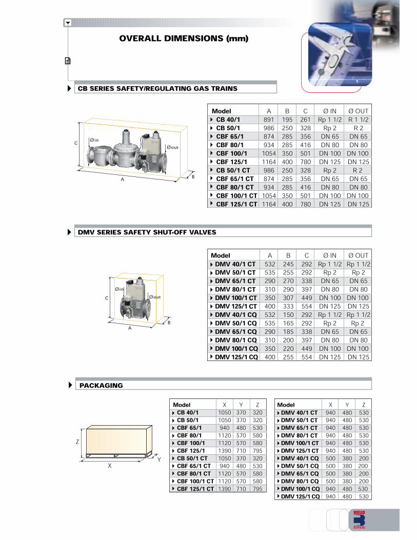
SAFETY/REGULATING GAS TRAINS CB seriesTechnical data of available models of CB seriesSAFETY SHUT-OFF VALVES DMV seriesTechnical data of available models of DMV seriesTECHNICAL DESCRIPTION - OPERATION (CB-DMV series)SELECTION DISGRAMS OF SAFETY/REGULATING GAS TRAINS (CB series) AND SAFETYSHUT-OFF VALVES (DMV series)INSTALLATION - START-UP - ADJUSTMENT (CB - DMV series)OVERALL DIMENSIONSSPECIFICATIONList of available modelsProduct constructive specificationState of supply
FOR PRESSURE REGULATING/REDUCING UNITS ACCESSORIESFOR SAFETY/REGULATING GAS TRAINS ACCESSORIESFOR SAFETY SHUT-OFF VALVES DMV ACCESSORIESSprings for gas governorConnection adaptorsManual valvesAnti-vibrating jointsFiltersPressure regulatorsPressure gauge kit + pulsing cockGas pressure switch for seal control installed on control panelSeal control kit
INDEX OF CONTENTS
PRESSURE REGULATING/REDUCING UNITS
The following index, divided in sections, allows search of arguments of interest inside the presentsheet.
SAFETY/REGULATING GAS TRAINS - SAFETY SHUT-OFF VALVES
ACCESSORIES

LOW PRESSURE REGULATING/REDUCING UNITS (Max inlet pressure = 0,5 bar) - LPRT series
6
4
5213
Low pressure regulating/reducing units of LPRT series are available in “thread ports” versions withdiameter from 3/4” to 2” and in “flanged” versions for with diameter from DN65 to DN150.
PRESSURE REGULATING/REDUCING UNITSLPRT and HPRT series units are systems for reduction and regulation of gas pressure assembledand tested in the factory to guarantee the maximum safety in operation and an easy installation.They are classified in low pressure and high pressure systems and are used when it is necessaryto regulate gas pressure available in the line to obtain values suited to the application.Pressure regulating/reducing units are integrating part of the burner and together they composea single system for gas combustion.
Regulators are equipped with BLU springs (pressure range 10-30 mbar).For higher pressure ranges, it is necessary to match springs selecting them from the ones availablein the accessories section.For industrial applications, it is advised the use of springs with pressure range of 60-110 mbar.For an inlet pressure ranges different from the ones indicated, it is necessary to contact RielloBurners Technical Department.
note
12
345
6
Manual shut-off valve (ball-valve)Gas filter GF type characterized by: Filtering degree ≤ = 50 µm Ambient temperature: -15 +80°C Gas family 1 - 2 - 3 (EN161)Filter replacement is possible without removing the armatureShut-off cockGas pressure gauge upstream to the stabilizerPressure regulator-stabilizer FRS type characterized by: Class A, group 2 (EN88) Ambient temperature: -15 +70°C Gas family 1 - 2 - 3 (EN161)Antivibrating joint
Model MAX Adjust. MAX MAX MAX MAX MAX MAX Port PortInlet range delivery delivery delivery delivery delivery delivery Ø IN Ø OUTpressure Out. press. METHANE LPG METHANE LPG METHANE LPG[mbar] [mbar] [Nmc/h] [Nmc/h] [Nmc/h] [Nmc/h] [Nmc/h] [Nmc/h]LPRT 40 500 60÷110 68 41 68 41 60 37 Rp 3/4” R 3/4”LPRT 80 500 60÷110 125 76 125 76 98 60 Rp 1” R 1”LPRT 160 500 60÷110 186 113 186 113 188 115 Rp 1” 1/2 R 1” 1/2LPRT 250 500 60÷110 310 189 310 189 305 186 Rp 2” R 2”LPRT 500 500 60÷110 500 305 500 305 441 269 DN 65 DN 65 LPRT 750 500 60÷110 600 366 600 366 567 346 DN 80 DN 80LPRT 1000 500 60÷110 1000 610 1000 610 955 583 DN 100 DN 100LPRT 1500 500 60÷110 1800 1098 1800 1098 1400 854 DN 125 DN 125LPRT 2000 500 60÷110 2800 1708 2800 1708 2100 1281 DN 150 DN 150
Inlet press. = 500 mbarOutlet press. = 100 mbar Inlet press. = 300 mbarOutlet press. = 100 mbar Inlet press. = 150 mbarOutlet press. = 100 mbarTechnical data of available models of LPRT series
GAS
OVERALL DIMENSIONS (mm)
X
ZY
C
BA
C
BA
ØoutØin
Model A B C Ø IN Ø OUTCB 40/1 891 195 261 Rp 1 1/2 R 1 1/2CB 50/1 986 250 328 Rp 2 R 2CBF 65/1 874 285 356 DN 65 DN 65CBF 80/1 934 285 416 DN 80 DN 80CBF 100/1 1054 350 501 DN 100 DN 100 CBF 125/1 1164 400 780 DN 125 DN 125CB 50/1 CT 986 250 328 Rp 2 R 2CBF 65/1 CT 874 285 356 DN 65 DN 65CBF 80/1 CT 934 285 416 DN 80 DN 80CBF 100/1 CT 1054 350 501 DN 100 DN 100CBF 125/1 CT 1164 400 780 DN 125 DN 125
ØoutØin
Model A B C Ø IN Ø OUTDMV 40/1 CT 532 245 292 Rp 1 1/2 Rp 1 1/2DMV 50/1 CT 535 255 292 Rp 2 Rp 2DMV 65/1 CT 290 270 338 DN 65 DN 65DMV 80/1 CT 310 290 397 DN 80 DN 80DMV 100/1 CT 350 307 449 DN 100 DN 100 DMV 125/1 CT 400 333 554 DN 125 DN 125DMV 40/1 CQ 532 150 292 Rp 1 1/2 Rp 1 1/2DMV 50/1 CQ 535 165 292 Rp 2 Rp 2DMV 65/1 CQ 290 185 338 DN 65 DN 65DMV 80/1 CQ 310 200 397 DN 80 DN 80DMV 100/1 CQ 350 220 449 DN 100 DN 100DMV 125/1 CQ 400 255 554 DN 125 DN 125
PACKAGING
DMV SERIES SAFETY SHUT-OFF VALVES
CB SERIES SAFETY/REGULATING GAS TRAINS
Model X Y ZCB 40/1 1050 370 320CB 50/1 1050 370 320CBF 65/1 940 480 530CBF 80/1 1120 570 580CBF 100/1 1120 570 580 CBF 125/1 1390 710 795CB 50/1 CT 1050 370 320CBF 65/1 CT 940 480 530CBF 80/1 CT 1120 570 580CBF 100/1 CT 1120 570 580CBF 125/1 CT 1390 710 795
Model X Y ZDMV 40/1 CT 940 480 530DMV 50/1 CT 940 480 530DMV 65/1 CT 940 480 530DMV 80/1 CT 940 480 530DMV 100/1 CT 940 480 530 DMV 125/1 CT 940 480 530DMV 40/1 CQ 500 380 200DMV 50/1 CQ 500 380 200DMV 65/1 CQ 500 380 200DMV 80/1 CQ 500 380 200DMV 100/1 CQ 940 480 530DMV 125/1 CQ 940 480 530

SPECIFICATION
Size : 40 - 50 - 65 - 80 - 100 - 125
Port : ... ThreadedF Flanged
CB F 65 /M 230/50-60
Regulation : /1 One stageSeal control : CT integrated... accessory (mountable)
Power supply : 230 V/ 50-60 Hz110 V/ 50-60 Hz
CT
Series : CB
/1
A specific index guides your choice of gas train and valve fromthe various models available in the CB and DMV series.A clear and detailed specification description of the productfollows.
LIST OF AVAILABLE MODELS
Seal control : CT integratedCQ Valve with additional gas pressure switch to be connected tothe seal control system installed on the control panel
Size : 40 - 50 - 65 - 80 - 100 - 125 - 150
DMV 65 230/50-60
Regulation : /1 One stage
Power supply : 230 V/ 50-60 Hz110 V/ 50-60 Hz
CT
Series : DMV
/1
CB 40/1CB 50/1CBF 65/1CBF 80/1CBF 100/1CBF 125/1CB 50/1 CTCBF 65/1 CTCBF 80/1 CTCBF 100/1 CTCBF 125/1 CT
DMV 40/1 CTDMV 50/1 CTDMV 65/1 CTDMV 80/1 CTDMV 100/1 CTDMV 125/1 CTDMV 40/1 CQDMV 50/1 CQDMV 65/1 CQDMV 80/1 CQDMV 100/1 CQDMV 125/1 CQ

1
2
34
5
6
7
Gas filter GF type: - filtering degree < = 50 µm- ambient temperature -15 ÷ 80°C- gas family 1 - 2 - 3 (EN161)- filter replacement is possible without removing the armaturePressure regulator-stabilizer FRS type: - class A, group 2 (EN88)- ambient temperature -15 ÷ 70°C- gas family 1 – 2 – 3 (EN161)Anti-dust filterSeal control VPS type: - according to EN 1643- voltage supply: ~AC 230/240V –15% + 10%, 50-60Hz; AC 110V, 50Hz;~AC 110/120 V, 60Hz; other voltage supplies available on request- ambient temperature: ~AC 50hz 230V –15 ÷ 70°C~AC 50Hz 110/120V –15 ÷ 60°C- gas family 1- 2 - 3- electrical protection degree IP 40 (IEC 529)- release time 10÷26s depending on test volumes and inlet pressure(according to EN 676 seal control is compulsory for burners with max. output more than 1200kW). Gas pressure switch at simple action GW type:- operation without outside power- temperature ranges- ambient temperature -15 ÷ 60°C- electrical protection degree IP54- adjustment tolerance ±15% switch point deviation based on the setpoint Gas safety solenoid valve normally closed DMV-DLE type:- automatic lock valve class A, group 2 EN161- ambient temperature -15 ÷ 60°C- voltage supply: AC 230/240V -15% +10%, 50-60Hz; other voltage supplies available on request- electrical protection degree IP 54- double diaphragm valve technology- slow opening with adjustable fast stroke for starting gas volume, adjustable up to approximatively 70% of total stroke- opening time of approximatively 20s at 20°C ambient temperature and without rapid stroke- fast closing (closing time <1s)- DC solenoid- compact, light-weight Gas regulating solenoid valve normally closed DMV-DLE type:- automatic lock valve class A, group 2 EN161- ambient temperature -15 ÷ 60°C- voltage supply: ~AC 220/240V -15% +10%, 50-60Hz; other voltage supplies available on request- electrical protection degree IP 54- double diaphragm valve technology- slow opening (opening time of approximatively 20s at ambient temperature of 20°C)- fast closing (closing time <1s)- DC solenoid- compact, light-weight- adjustable main volume- mountable closed position signal contact
Model MAX inlet pressure Voltage supply Port Port[mbar] [V/Hz] Ø IN Ø OUTCB 40/1 500 230/50-60 Rp 1 1/2 R 1 1/2CB 50/1 500 230/50-60 Rp 2 R 2CBF 65/1 500 230/50-60 DN 65 DN 65CBF 80/1 500 230/50-60 DN 80 DN 80CBF 100/1 500 230/50-60 DN 100 DN 100
CBF 125/1 500 230/50-60 DN 125 DN 125CB 50/1 CT 500 230/50-60 Rp 2 R 2CBF 65/1 CT 500 230/50-60 DN 65 DN 65CBF 80/1 CT 500 230/50-60 DN 80 DN 80CBF 100/1 CT 500 230/50-60 DN 100 DN 100CBF 125/1 CT 500 230/50-60 DN 125 DN 125
Regulators are equipped with BLU springs (pressure range10-30 mbar).For higher pressure ranges, springs have to be selected fromthe ones available listed in accessories section.note
Technical data available models CB series
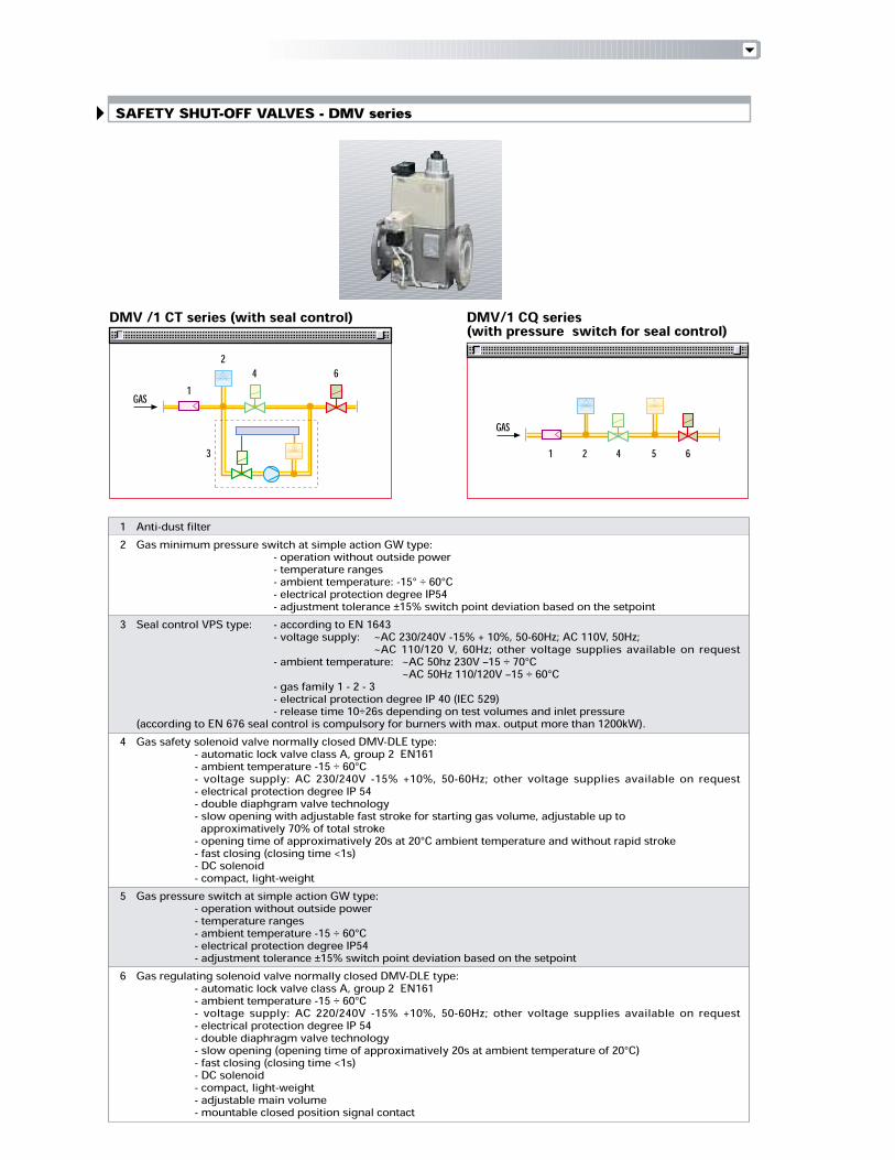
SAFETY SHUT-OFF VALVES - DMV series
DMV/1 CQ series(with pressure switch for seal control)DMV /1 CT series (with seal control)
2 5 6413
61
2 4
GASGAS
12
3
4
5
6
Anti-dust filterGas minimum pressure switch at simple action GW type:- operation without outside power - temperature ranges - ambient temperature: -15° ÷ 60°C - electrical protection degree IP54 - adjustment tolerance ±15% switch point deviation based on the setpointSeal control VPS type: - according to EN 1643- voltage supply: ~AC 230/240V -15% + 10%, 50-60Hz; AC 110V, 50Hz;~AC 110/120 V, 60Hz; other voltage supplies available on request- ambient temperature: ~AC 50hz 230V –15 ÷ 70°C~AC 50Hz 110/120V –15 ÷ 60°C- gas family 1 - 2 - 3- electrical protection degree IP 40 (IEC 529)- release time 10÷26s depending on test volumes and inlet pressure(according to EN 676 seal control is compulsory for burners with max. output more than 1200kW).Gas safety solenoid valve normally closed DMV-DLE type:- automatic lock valve class A, group 2 EN161- ambient temperature -15 ÷ 60°C- voltage supply: AC 230/240V -15% +10%, 50-60Hz; other voltage supplies available on request- electrical protection degree IP 54- double diaphgram valve technology- slow opening with adjustable fast stroke for starting gas volume, adjustable up to approximatively 70% of total stroke- opening time of approximatively 20s at 20°C ambient temperature and without rapid stroke- fast closing (closing time <1s)- DC solenoid- compact, light-weightGas pressure switch at simple action GW type:- operation without outside power- temperature ranges- ambient temperature -15 ÷ 60°C- electrical protection degree IP54- adjustment tolerance ±15% switch point deviation based on the setpointGas regulating solenoid valve normally closed DMV-DLE type:- automatic lock valve class A, group 2 EN161- ambient temperature -15 ÷ 60°C- voltage supply: AC 220/240V -15% +10%, 50-60Hz; other voltage supplies available on request- electrical protection degree IP 54- double diaphragm valve technology- slow opening (opening time of approximatively 20s at ambient temperature of 20°C)- fast closing (closing time <1s)- DC solenoid- compact, light-weight- adjustable main volume- mountable closed position signal contact
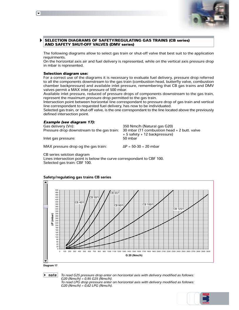
SELECTION DIAGRAMS OF SAFETY/REGULATING GAS TRAINS (CB series)AND SAFETY SHUT-OFF VALVES (DMV series)
Diagram 17
Safety/regulating gas trains CB series
The following diagrams allow to select gas train or shut-off valve that best suit to the applicationrequirments.On the horizontal axis air and fuel delivery is represented, while on the vertical axis pressure dropin mbar is represented.Selection diagram use:For a correct use of the diagrams it is necessary to evaluate fuel delivery, pressure drop referredto all the components downstream to the gas train (combustion head, butterfly valve, combustionchamber backpressure) and available inlet pressure, remembering that CB gas trains and DMVvalves permit a MAX inlet pressure of 500 mbar.Available inlet pressure, reduced of pressure drops of components downstream to the gas train,represent the maximum pressure drop permitted to the gas train.Intersection point between horizontal line correspondant to pressure drop of gas train and verticalline correspondant to requested fuel delivery, has now to be individuated.Selected gas train, or shut-off valve, is the one correspondant to the line located above the previouslydefined intersection point.Example (see diagram 17):Gas delivery (Vn): 350 Nmc/h (Natural gas G20)Pressure drop downstream to the gas train: 30 mbar (11 combustion head + 2 butt. valve+ 5 safety + 12 backpressure)Inlet gas pressure: 50 mbarMAX pressure drop og the gas train: ∆P = 50-30 = 20 mbarCB series selction diagramLines intersection point is below the curve correspondant to CBF 100.Selected gas train: CBF 100.
020406080100120140160180200220240260280300320340360380400420440460480500
0 100 200 300 400 500 600 700 800 900 1000 1100 1200 1300 1400 1500 1600 1700 1800 1900 2000 2100 2200 2300 2400 2500 2600 2700 2800 2900 3000
G 20 (Nmc/h)
∆P (mbar)
CB 40/1CB 50/1
CB 65/1
CB 80/1 CB 100/1CB 125/1
To read G25 pressure drop enter on horizontal axis with delivery modified as follows:G20 (Nmc/h) = 0,95 G25 (Nmc/h).To read LPG drop pressure enter on horizontal axis with delivery modified as follows:G20 (Nmc/h) = 0,62 LPG (Nmc/h).note

Installation of safety/regulating gas trains of CB series and safety shut-off valves of DMV series isa very simple and quick procedure because units are pre-assembled and tested in the factory.Connection to the gas distribution system takes place through threaded ports and must be realizedwith an approppriate hermetic material, so to gaurantee junctions seal (Teflon, Loctite,ect…).Connection through flanges must be effectuated with gaskets; fixing screws must be held withcrossed sequence.
Electrical connection of valves and seal control is made by means of terminals (pos. 1 fig. 19).At start-up it is necessary to verify that inlet pressure does not exceed the max. admitted to avoiddamages to the regulation devices.CB trains and DMV valves aloow regulation of opening time with adjustable fast stroke for startinggas volume, by acting on the appropriate screw (pos. 2 fig. 19) that is located at the top of the gastrain.Main delivery regulation is made by acting on adjustment knob that is also located at the top of thegas train (pos. 3 fig. 19).Pressure regulator-stabilizer in CB trains allow outlet pressure regulation by acting on adjustmentknob that is located at the top of the regulator.Regulation range of outlet pressure depends on the selected spring.VPS seal control doesn’t need any regulation; an operation check could be realized by opening thescrew of pressure port during testing time (or pumping time) so to simulate a pressure drop andverify seal control correct working.
Diagram 18
Safety shut-off valves DMV series
Diagram 19
INSTALLATION - START-UP - ADJUSTMENT (CB, DMV series)
231
DM
V 40
/1D
MV
50/1
DM
V 65
/1D
MV
80/1
DM
V 10
0/1
DM
V 12
5/1
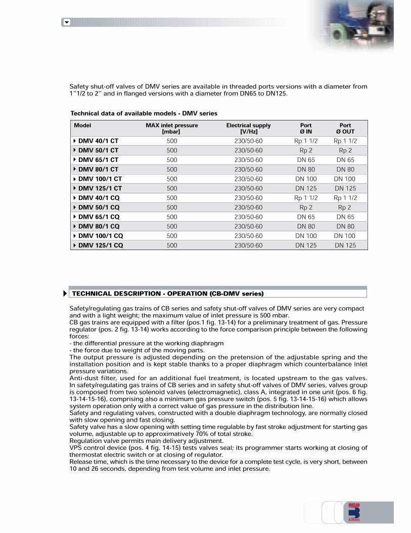
TECHNICAL DESCRIPTION - OPERATION (CB-DMV series)
Technical data of available models - DMV seriesModel MAX inlet pressure Electrical supply Port Port[mbar] [V/Hz] Ø IN Ø OUT
DMV 40/1 CT 500 230/50-60 Rp 1 1/2 Rp 1 1/2DMV 50/1 CT 500 230/50-60 Rp 2 Rp 2DMV 65/1 CT 500 230/50-60 DN 65 DN 65DMV 80/1 CT 500 230/50-60 DN 80 DN 80DMV 100/1 CT 500 230/50-60 DN 100 DN 100
DMV 125/1 CT 500 230/50-60 DN 125 DN 125DMV 40/1 CQ 500 230/50-60 Rp 1 1/2 Rp 1 1/2DMV 50/1 CQ 500 230/50-60 Rp 2 Rp 2DMV 65/1 CQ 500 230/50-60 DN 65 DN 65DMV 80/1 CQ 500 230/50-60 DN 80 DN 80DMV 100/1 CQ 500 230/50-60 DN 100 DN 100DMV 125/1 CQ 500 230/50-60 DN 125 DN 125
Safety shut-off valves of DMV series are available in threaded ports versions with a diameter from1”1/2 to 2” and in flanged versions with a diameter from DN65 to DN125.
Safety/regulating gas trains of CB series and safety shut-off valves of DMV series are very compactand with a light weight; the maximum value of inlet pressure is 500 mbar.CB gas trains are equipped with a filter (pos.1 fig. 13-14) for a preliminary treatment of gas. Pressureregulator (pos. 2 fig. 13-14) works according to the force comparison principle between the followingforces:- the differential pressure at the working diaphragm- the force due to weight of the moving parts.The output pressure is adjusted depending on the pretension of the adjustable spring and theinstallation position and is kept stable thanks to a proper diaphragm which counterbalance inletpressure variations.Anti-dust filter, used for an additional fuel treatment, is located upstream to the gas valves.In safety/regulating gas trains of CB series and in safety shut-off valves of DMV series, valves groupis composed from two solenoid valves (electromagnetic), class A, integrated in one unit (pos. 6 fig.13-14-15-16), comprising also a minimum gas pressure switch (pos. 5 fig. 13-14-15-16) which allowssystem operation only with a correct value of gas pressure in the distribution line.Safety and regulating valves, constructed with a double diaphragm technology, are normally closedwith slow opening and fast closing.Safety valve has a slow opening with setting time regulable by fast stroke adjustment for starting gasvolume, adjustable up to approximatively 70% of total stroke.Regulation valve permits main delivery adjustment.VPS control device (pos. 4 fig. 14-15) tests valves seal; its programmer starts working at closing ofthermostat electric switch or at closing of regulator.Release time, which is the time necessary to the device for a complete test cycle, is very short, between10 and 26 seconds, depending from test volume and inlet pressure.
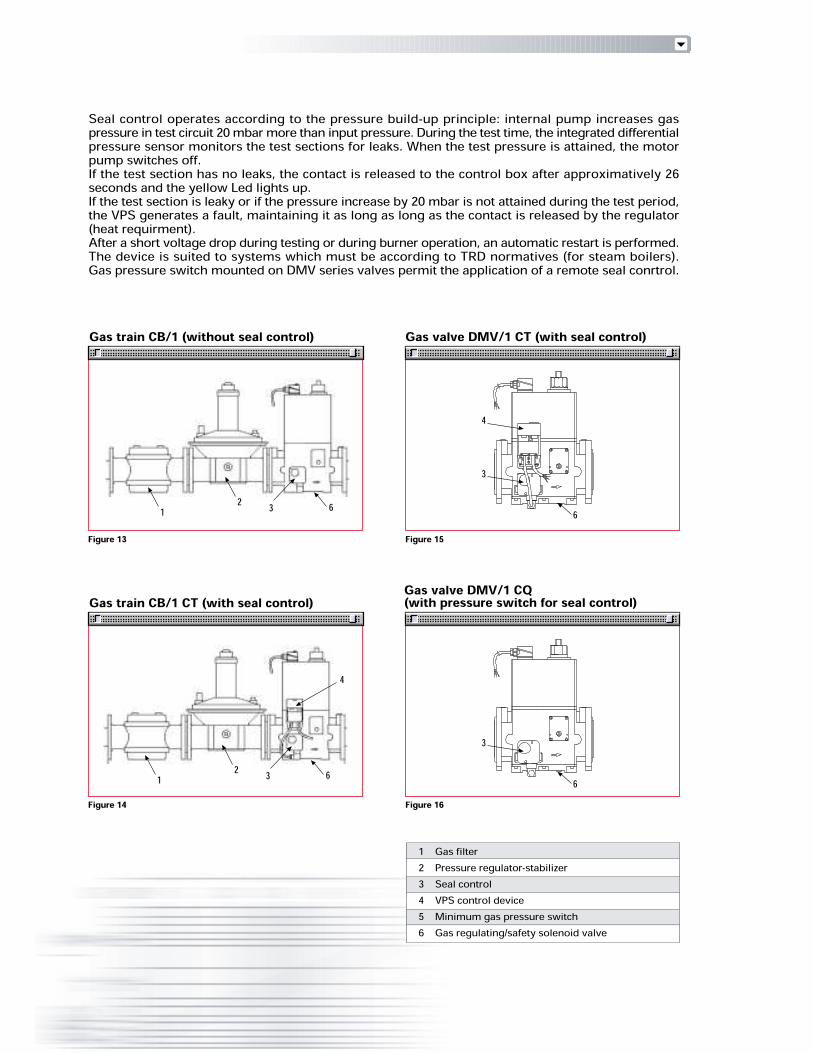
123456
Figure 13
Figure 14
Figure 15
Figure 16
Gas train CB/1 (without seal control)
Gas train CB/1 CT (with seal control) Gas valve DMV/1 CQ(with pressure switch for seal control)
Gas valve DMV/1 CT (with seal control)
Gas filterPressure regulator-stabilizerSeal controlVPS control deviceMinimum gas pressure switchGas regulating/safety solenoid valve
Seal control operates according to the pressure build-up principle: internal pump increases gaspressure in test circuit 20 mbar more than input pressure. During the test time, the integrated differentialpressure sensor monitors the test sections for leaks. When the test pressure is attained, the motorpump switches off.If the test section has no leaks, the contact is released to the control box after approximatively 26seconds and the yellow Led lights up.If the test section is leaky or if the pressure increase by 20 mbar is not attained during the test period,the VPS generates a fault, maintaining it as long as long as the contact is released by the regulator(heat requirment).After a short voltage drop during testing or during burner operation, an automatic restart is performed.The device is suited to systems which must be according to TRD normatives (for steam boilers).Gas pressure switch mounted on DMV series valves permit the application of a remote seal conrtrol.
4
3
6
3
6
3 621
3 621
4

Pressure regulating/reducing units and safety/regulating gas trainshave common accessories. The following section shows a widedescription of available accessories.Springs for pressure regulatorAccessories springs are available for varying pressure range of the regulator-stabilizer includedin the regulating/reducing unit or in CB train.In the following table, the springs are listed with their application range.
ACCESSORIES FOR PRESSUREREGULATING/REDUCING UNITS -SAFETY/REGULATING GAS TRAINS -SAFETY SHUT-OFF VALVES
Springs for pressure regulators CB and LPRT series
CB 40CB 40CB 40CB 40CB 50CB 50CB 50CB 50CBF 65/80CBF 65/80CBF 65/80CBF 65/80CBF 65/80CBF 100CBF 100CBF 100CBF 100CBF 100CBF 125CBF 125CBF 125CBF 125
Type Code
301013130101573090486301013230101583090487301013330101353090456301013430101363090489
LPRT 40LPRT 40LPRT 40LPRT 40LPRT 80LPRT 80LPRT 80LPRT 80LPRT 160LPRT 160LPRT 160LPRT 160LPRT 250LPRT 250LPRT 250LPRT 250LPRT 500/750LPRT 500/750LPRT 500/750LPRT 500/750LPRT 500/750LPRT 1000LPRT 1000LPRT 1000LPRT 1000LPRT 1000LPRT 1500LPRT 1500LPRT 1500LPRT 1500LPRT 2000LPRT 2000LPRT 2000LPRT 2000
Type Outletpressure [mbar]25÷5530÷7060÷110
90÷15025÷5530÷7060÷110
90÷15025÷5530÷7060÷11090÷15025÷5530÷7060÷11090÷15025÷5530÷7060÷11090÷150
140÷20025÷5530÷7060÷11090÷150
140÷20025÷5530÷7060÷11090÷15025÷5530÷7060÷11090÷150
PortRp 3/4”Rp 3/4”Rp 3/4”Rp 3/4”Rp 1”Rp 1”Rp 1”Rp 1”
Rp 1”1/2Rp 1”1/2Rp 1”1/2Rp 1”1/2
Rp 2”Rp 2”Rp 2”Rp 2”
DN 65/80DN 65/80DN 65/80DN 65/80DN 65/80DN 100DN 100DN 100DN 100DN 100DN 125DN 125DN 125DN 125DN 150DN 150DN 150DN 150
SpringRed
YellowBlackPinkRed
YellowBlackPinkRed
YellowBlackPinkRed
YellowBlackPinkRed
YellowBlackPinkGreyRed
YellowBlackPinkGreyRedYellow
BlackPinkRed
YellowBlackPink

123456789
Shut-off ball valveGas filterPressure regulatorAnti-vibrating jointPressure gauge upstream to the regulatorShut-off cockPressure relief valveSafety slam-shut valvePressure gauge downstream to the regulator
LPRT 40-80-160-250 LPRT 500-750-1000-1500-2000
HPRT 80-160-250-500-750 HPRT 1000-1500-2000
Figure 1
Figure 3
Figure 2
Figure 4
35
6 4
21
TECHNICAL DESCRIPTION - OPERATION (LPRT - HPRT series)Pressure regulating/reducing units of LPRT and HPRT series are equipped with a shut-off ball valve(pos.1 fig. 1-2-3-4) and a filter (pos.2 fig. 1-2-3-4) for a preliminary treatment of inlet gas.Pressure regulators installed on LPRT series units (pos.3 fig. 1-2) works according to the forcecomparison principle between the following forces:- the differential pressure at the working diaphragm- the force due to weight of the moving partsThe output pressure is adjusted depending on the pretension of the adjustable spring and theinstallation position.Pressure regulators installed on HPRT series units (pos.3 fig. 3-4) are direct action devices, controlledby a diaphragm and counterspring.Safety slam-shut valve (pos.8 fig. 3-4) is a device which blocks gas flow when the downstreampressure modifies, increasing or decreasing, up to the intervention set-point, or if it is actuatedmanually.The pressure relief valve (pos.7 fig. 3-4) is a device mounted to avoid that small leak (when thereis no flow required) or sudden and temporary overpressures (such as deriving from rapid switchingor overheating of the gas) cause intervention of the slam shut.Pressure gauges with shut-off cock mounted upstream (pos.5-6 fig.1-2-3-4) or downstream (pos.6-9 fig. 3-4) to the regulator allow pressure monitoring.Antivibrating joint (pos.4 fig. 1-2-3-4) permits to damp vibrations and a simple connection to the gasdistribution circuit.
35
6 4
21
354
21
67 9
8
6 354
216
7 986
PRODUCT CONSTRUCTIVE SPECIFICATIONCB seriesSafety/regulating gas train for gas of 1st - 2nd - 3rd family, with MAX supply pressure of 500 mbarcomposed from:- 1 gas filter with filtering degree lower than 50 µm- 1 pressure regulator-stabilizer, for stabilizing gas inlet pressure to the burner with a ±5% max.tolerance respect the fixed value- 1 valves unit composed from two automatic closing valves EN 161, class A, group 2, realized withdouble diaphragm technology, comprised in a single body and featured by:- fast closing and slow opening with adjustable fast stroke for initial gas volume- adjustable main delivery- ant-dust filter with net- 1 minimum gas pressure switch that allows system working only with a suited pressure in thegas distribution line- 1 automatic seal control with a release time of 10÷26 seconds (when equipped)- nipples (in threaded version)- gaskets (in flanged version)- fixing screws (in flanged version).DMV seriesSafety shut-off valve for gas of 1st - 2nd - 3rd family, with MAX supply pressure of 500 mbarcomposed from:- 1 valves unit composed from two automatic closing valves EN 161, class A, group 2, realized withdouble diaphragm technology, comprised in a single body and featured by:- fast closing and slow opening with adjustable fast stroke for initial gas volume- adjustable main delivery- ant-dust filter with net- 1 automatic seal control with a release time of 10÷26 seconds (when equipped)- nipples (in threaded version)- gaskets (in flanged version)- fixing screws (in flanged version).Standard equipment:- instruction handbook for installation, use and maintenance- gaskets (in flanged version)- fixing screws (in flanged version)- electrical connection terminals.Available accessories to be ordered separately (see accessories section):- spring for pressure regulator- manual shut-off valve (ball valve from 3/4” to 2”, from DN65 to DN150)- anti-vibrating joint (from 3/4” to 2”, from DN65 to DN150)- filter (1”1/2, 2”, DN65, DN100, DN125)- pressure regulator (1”1/2, 2”, DN65, DN100, DN125)- pressure gauge kit with push-button (for pressure of 60, 150, 300, 500 mbar, 1-4 bar)- connection adaptor- gas pressure switch for seal control- seal control kit
STATE OF SUPPLYSafety/regulating gas trains of CB series anf safety shut-off valves of DMV series are supplied pre-assembled and tested in the factory, packaged in carton boxes or wood cases.The supply includes:- gas train or safety shut-off valve- seal control pre-assembled (when equipped)- instruction handbook for installation, use and maintenance- gaskets (in flanged version)- fixing screws (in flanged version)- electrical connection terminals
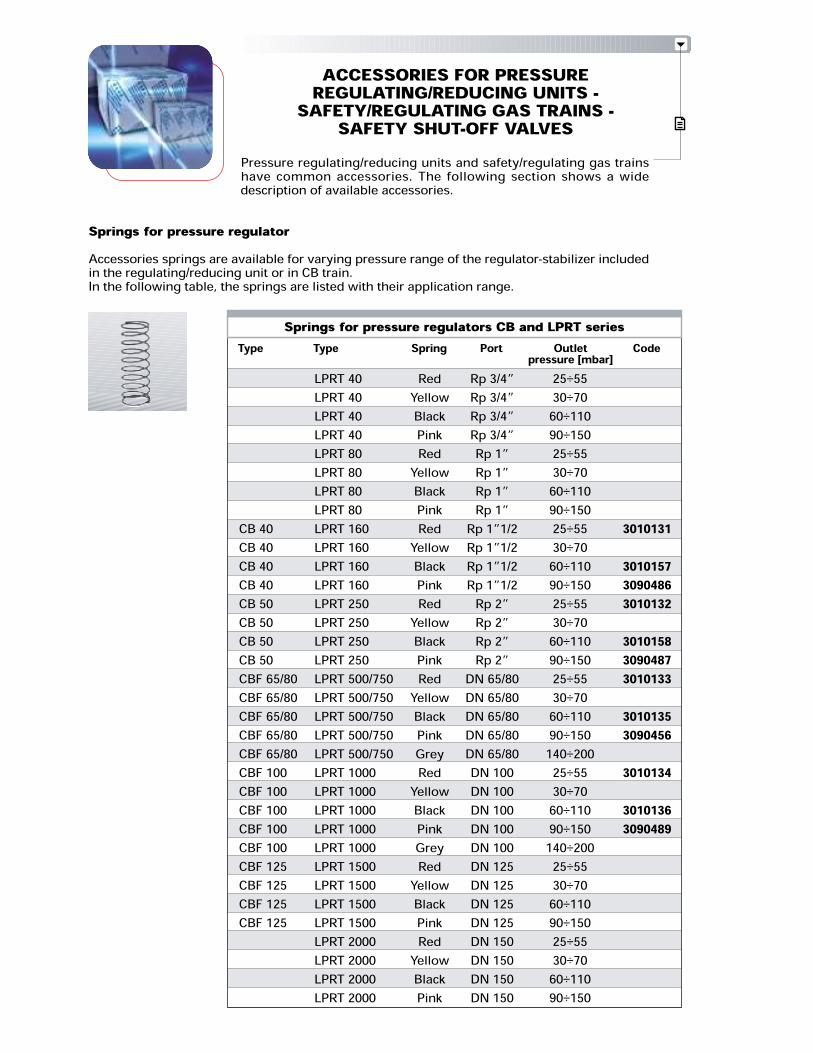
Pressure regulating/reducing units and safety/regulating gas trainshave common accessories. The following section shows a widedescription of available accessories.Springs for pressure regulatorAccessories springs are available for varying pressure range of the regulator-stabilizer includedin the regulating/reducing unit or in CB train.In the following table, the springs are listed with their application range.
ACCESSORIES FOR PRESSUREREGULATING/REDUCING UNITS -SAFETY/REGULATING GAS TRAINS -SAFETY SHUT-OFF VALVES
Springs for pressure regulators CB and LPRT series
CB 40CB 40CB 40CB 40CB 50CB 50CB 50CB 50CBF 65/80CBF 65/80CBF 65/80CBF 65/80CBF 65/80CBF 100CBF 100CBF 100CBF 100CBF 100CBF 125CBF 125CBF 125CBF 125
Type Code
301013130101573090486301013230101583090487301013330101353090456301013430101363090489
LPRT 40LPRT 40LPRT 40LPRT 40LPRT 80LPRT 80LPRT 80LPRT 80LPRT 160LPRT 160LPRT 160LPRT 160LPRT 250LPRT 250LPRT 250LPRT 250LPRT 500/750LPRT 500/750LPRT 500/750LPRT 500/750LPRT 500/750LPRT 1000LPRT 1000LPRT 1000LPRT 1000LPRT 1000LPRT 1500LPRT 1500LPRT 1500LPRT 1500LPRT 2000LPRT 2000LPRT 2000LPRT 2000
Type Outletpressure [mbar]25÷5530÷7060÷110
90÷15025÷5530÷7060÷110
90÷15025÷5530÷7060÷11090÷15025÷5530÷7060÷11090÷15025÷5530÷7060÷11090÷150
140÷20025÷5530÷7060÷11090÷150
140÷20025÷5530÷7060÷11090÷15025÷5530÷7060÷11090÷150
PortRp 3/4”Rp 3/4”Rp 3/4”Rp 3/4”Rp 1”Rp 1”Rp 1”Rp 1”
Rp 1”1/2Rp 1”1/2Rp 1”1/2Rp 1”1/2
Rp 2”Rp 2”Rp 2”Rp 2”
DN 65/80DN 65/80DN 65/80DN 65/80DN 65/80DN 100DN 100DN 100DN 100DN 100DN 125DN 125DN 125DN 125DN 150DN 150DN 150DN 150
SpringRed
YellowBlackPinkRed
YellowBlackPinkRed
YellowBlackPinkRed
YellowBlackPinkRed
YellowBlackPinkGreyRed
YellowBlackPinkGreyRedYellow
BlackPinkRed
YellowBlackPink

OVERALL DIMENSIONS (mm)
LOW PRESSURE REGULATING/REDUCING UNITS (LPRT series)
HIGH PRESSURE REGULATING/REDUCING UNITS (HPRT series)
X
ZY
PACKAGING
Model A B C Ø IN Ø OUTHPRT 80 1223 180 400 Rp 1 1/2 R 1 1/2HPRT 160 1275 180 410 Rp 1 1/2 R 2HPRT 250 1200 280 560 Rp 2 DN 65HPRT 500 1750 280 560 DN 65 DN 65HPRT 750 1890 280 560 DN 80 DN 80HPRT 1000 2070 380 560 DN 100 DN 100HPRT 1500 2120 500 650 DN 100 DN 100HPRT 2000 2150 500 650 DN 125 DN 125
Model A B C Ø IN Ø OUTLPRT 40 532 245 292 Rp 3/4 R 3/4LPRT 80 310 290 397 Rp 1 R 1LPRT 160 350 307 449 Rp 1 1/2 R 1 1/2LPRT 250 400 333 554 Rp 2 R 2LPRT 500 532 150 292 DN 65 DN 65LPRT 750 535 165 292 DN 80 DN 80LPRT 1000 290 185 338 DN 100 DN 100LPRT 1500 310 200 397 DN 125 DN 125LPRT 2000 350 220 449 DN 150 DN 150
Model X Y ZHPRT 80 1230 460 560HPRT 160 1230 460 560HPRT 250 1230 460 560HPRT 500 1300 530 590HPRT 750 1300 530 590HPRT 1000 1300 530 590HPRT 1500 1390 710 795HPRT 2000 1390 710 795
Model X Y ZLPRT 40 532 245 292LPRT 80 310 290 397LPRT 160 350 307 449LPRT 250 400 333 554LPRT 500 532 150 292LPRT 750 535 165 292LPRT 1000 290 185 338LPRT 1500 310 200 397LPRT 2000 350 220 449
C
BA
ØoutØin
C
BA
ØoutØin

SPECIFICATION
A specific index guides your choice of pressureregulating/reducing unit from the various models availablein the LPRT and HPRT series.A clear and detailed specification description of the productfollows.
PRODUCT CONSTRUCTIVE SPECIFICATIONLPRT seriesLow pressure regulating/reducing unit, for gas of 1 - 2 - 3 family, with max. inlet pressure of 500mbar composed by:- 1 manual shut-off valve (ball valve)- 1 gas filter with filtering degree lower than 50 mm- 1 gas pressure gauge, with shut-off push-button cock, located upstraem to the regulator- 1 pressure regulator-stabilizer- 1 anti-vibrating joint- nipples (in threaded version)- gaskets (in flanged version)- fixing screws (in flanged version).HPRT seriesHigh pressure regulating/reducing unit, for gas of 1 - 2 - 3 family, with max. inlet pressure of 4 barcomposed by:- 1 manual shut-off valve (ball valve)- 1 gas filter with filtering degree lower than 50 mm- 1 gas pressure gauge, with shut-off push-button cock, located upstrem to the regulator- 2 connection stubs- 1 pressure regulator-stabilizer- 1 slam-shut valve- 1 gas pressure gauge, with shut-off push-button cock, located downstrem to the regulator- 2 pipelines for sensing line- 1 vent valve- 1 antivibrating joint- nipples (in threaded version)- gaskets (in flanged version)- fixing screws (in flanged version).
Size : 40 - 80 - 160 - 250 - 500 - 750 - 1000 - 1500 - 2000
LPRT 160
Series : LPRT Low pressure regulating/reducing unitHPRT High pressure regulating/reducing unit
LIST OF AVAILABLE MODELSHPRT 80HPRT 160HPRT 250HPRT 500HPRT 750HPRT 1000HPRT 1500HPRT 2000
LPRT 40LPRT 80LPRT 160LPRT 250LPRT 500LPRT 750LPRT 1000LPRT 1500LPRT 2000

Diagram 9
Diagram 10
Diagram 11
HPRT series - Outlet pressure 60 mbar
Reference conditions:Gas temperature 20°CG20 density: 0,71 kg/m3G25 density: 0,78 kg/m3LPG density: 1,98 kg/m3
HPRT series - Outlet pressure 110 mbar
Reference conditions:Gas temperature 20°CG20 density: 0,71 kg/m3G25 density: 0,78 kg/m3LPG density: 1,98 kg/m3
HPRT series - Outlet pressure 150 mbar
Reference conditions:Gas temperature 20°CG20 density: 0,71 kg/m3G25 density: 0,78 kg/m3LPG density: 1,98 kg/m3

INSTALLATION - START UP - ADJUSTMENT (LPRT - HPRT series)
Diagram 12
HPRT series - Outlet pressure 220 mbar
Reference conditions:Gas temperature 20°CG20 density: 0,71 kg/m3G25 density: 0,78 kg/m3LPG density: 1,98 kg/m3
Pressure regulating/reducing units of LPRT and HPRT series installation is a very simple and quickprocedure because units are pre-assembled and tested in the factory.Connection to the gas distribution system takes place through threaded ports and must be realizedwith an approppriate hermetic material, so to gaurantee junctions seal (Teflon, Loctite,ect…).Connection through flanges must be effectuated with gaskets; fixing screws must be held withcrossed sequence.At start-up, keeping in close position the valves downstream to the regulating/reducing unit, openslowly the manual shut-off valve (ball valve - pos.1 fig. 1-2-3-4) and verify, through the pressuregauge upstream to the regulator, that inlet pressure do not exceed the maximum accepted fromthe regulating/reducing unit.In case of a too high pressure value, close immediately the manual shut-off valve so to avoiddamages to the regulation devices.Once inlet pressure has been found correct, it is possible to regulate outlet pressure by interveningon the regulation device which is at the top of pressure regulating/reducing unit.Outlet pressure regulation range is in relation to the selected spring.
Standard equipment:- instruction handbook for installation, use and maintenance- gaskets (in flanged version)- fixing screws (in flanged version).Available accessories to be ordered separately (see accessories section):- spring for pressure regulator- manual shut-off valve (ball valve from 3/4” to 2”, from DN65 to DN150)- anti-vibrating joint (from 3/4” to 2”, from DN65 to DN150)- filter (1”1/2, 2”, DN65, DN100, DN125)- pressure regulator (1”1/2, 2”, DN65, DN100, DN125)- pressure gauge kit with push-button (for pressure of 60, 150, 300, 500 mbar, 1-4 bar).
STATE OF SUPPLYPressure regulating/reducing units of LPRT/HPRT series are supplied pre-assembled and tested in thefactory, protected from a nylon cover and packaged in carton boxes or wood cases.The supply includes:- pressure regulating/reducing unit- gaskets (in flanged version)- fixing screws (in flanged version)- instruction handbook for installation, use and maintenance
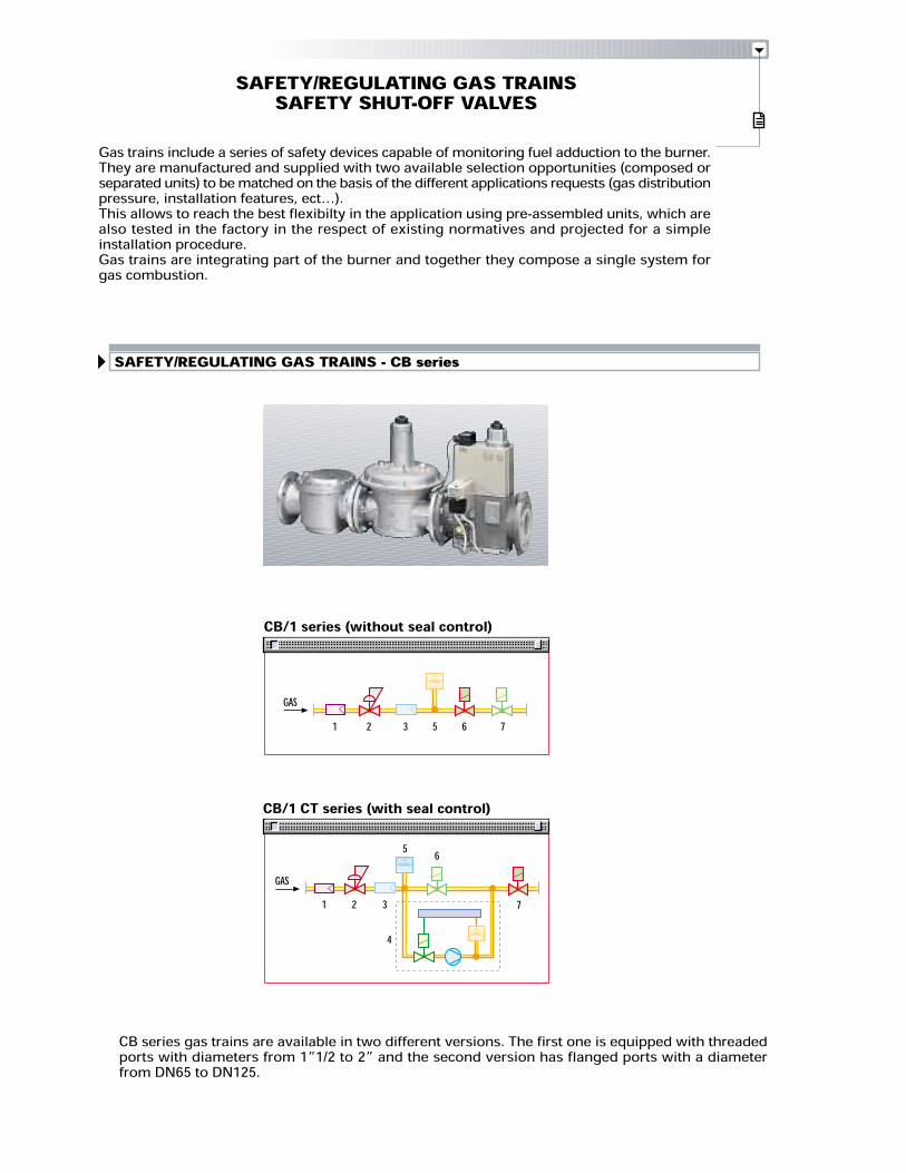
SAFETY/REGULATING GAS TRAINS - CB series
CB/1 series (without seal control)
CB/1 CT series (with seal control)
GAS
GAS
1 2 3 5 76
3
5
7
6
421
SAFETY/REGULATING GAS TRAINSSAFETY SHUT-OFF VALVESGas trains include a series of safety devices capable of monitoring fuel adduction to the burner.They are manufactured and supplied with two available selection opportunities (composed orseparated units) to be matched on the basis of the different applications requests (gas distributionpressure, installation features, ect…).This allows to reach the best flexibilty in the application using pre-assembled units, which arealso tested in the factory in the respect of existing normatives and projected for a simpleinstallation procedure.Gas trains are integrating part of the burner and together they compose a single system forgas combustion.
CB series gas trains are available in two different versions. The first one is equipped with threadedports with diameters from 1”1/2 to 2” and the second version has flanged ports with a diameterfrom DN65 to DN125.
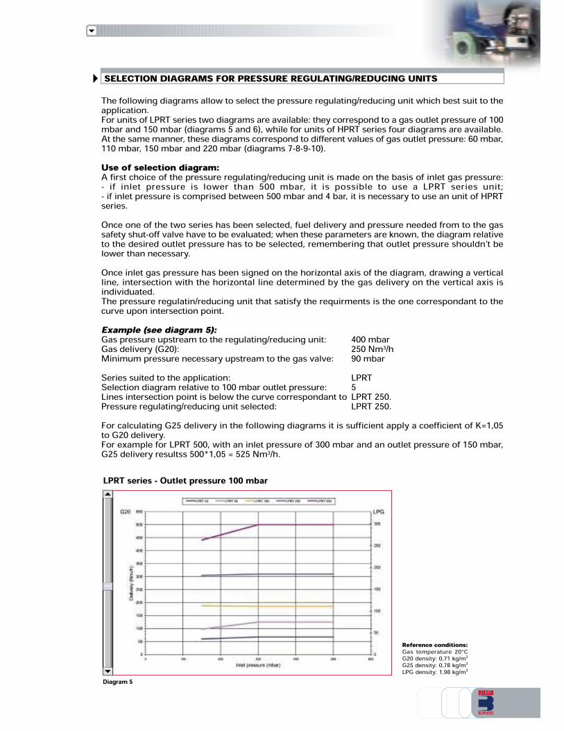
Diagram 5
Reference conditions:Gas temperature 20°CG20 density: 0,71 kg/m3G25 density: 0,78 kg/m3LPG density: 1,98 kg/m3
LPRT series - Outlet pressure 100 mbar
SELECTION DIAGRAMS FOR PRESSURE REGULATING/REDUCING UNITSThe following diagrams allow to select the pressure regulating/reducing unit which best suit to theapplication.For units of LPRT series two diagrams are available: they correspond to a gas outlet pressure of 100mbar and 150 mbar (diagrams 5 and 6), while for units of HPRT series four diagrams are available.At the same manner, these diagrams correspond to different values of gas outlet pressure: 60 mbar,110 mbar, 150 mbar and 220 mbar (diagrams 7-8-9-10).Use of selection diagram:A first choice of the pressure regulating/reducing unit is made on the basis of inlet gas pressure:- if inlet pressure is lower than 500 mbar, it is possible to use a LPRT series unit;- if inlet pressure is comprised between 500 mbar and 4 bar, it is necessary to use an unit of HPRTseries.Once one of the two series has been selected, fuel delivery and pressure needed from to the gassafety shut-off valve have to be evaluated; when these parameters are known, the diagram relativeto the desired outlet pressure has to be selected, remembering that outlet pressure shouldn’t belower than necessary.Once inlet gas pressure has been signed on the horizontal axis of the diagram, drawing a verticalline, intersection with the horizontal line determined by the gas delivery on the vertical axis isindividuated.The pressure regulatin/reducing unit that satisfy the requirments is the one correspondant to thecurve upon intersection point.Example (see diagram 5):Gas pressure upstream to the regulating/reducing unit: 400 mbarGas delivery (G20): 250 Nm3/hMinimum pressure necessary upstream to the gas valve: 90 mbarSeries suited to the application: LPRTSelection diagram relative to 100 mbar outlet pressure: 5Lines intersection point is below the curve correspondant to LPRT 250.Pressure regulating/reducing unit selected: LPRT 250.For calculating G25 delivery in the following diagrams it is sufficient apply a coefficient of K=1,05to G20 delivery.For example for LPRT 500, with an inlet pressure of 300 mbar and an outlet pressure of 150 mbar,G25 delivery resultss 500*1,05 = 525 Nm3/h.
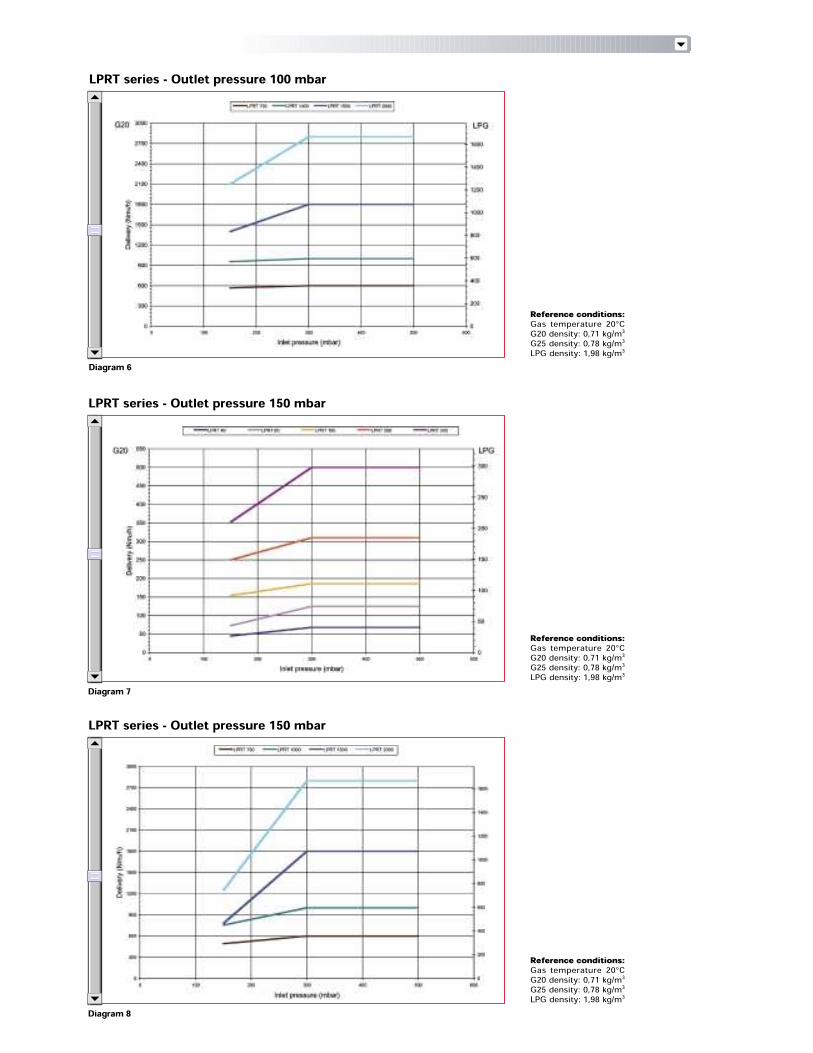
Diagram 6
Diagram 7
Diagram 8
LPRT series - Outlet pressure 100 mbar
Reference conditions:Gas temperature 20°CG20 density: 0,71 kg/m3G25 density: 0,78 kg/m3LPG density: 1,98 kg/m3
LPRT series - Outlet pressure 150 mbar
Reference conditions:Gas temperature 20°CG20 density: 0,71 kg/m3G25 density: 0,78 kg/m3LPG density: 1,98 kg/m3
LPRT series - Outlet pressure 150 mbar
Reference conditions:Gas temperature 20°CG20 density: 0,71 kg/m3G25 density: 0,78 kg/m3LPG density: 1,98 kg/m3
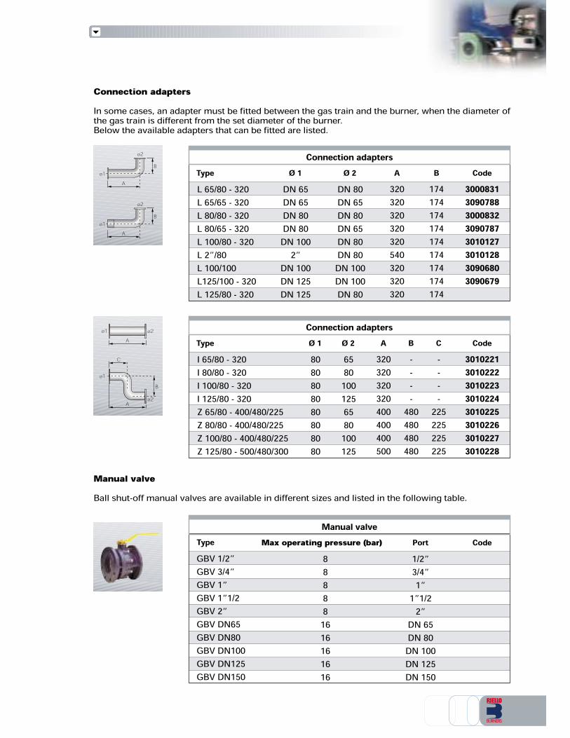
Connection adaptersL 65/80 - 320L 65/65 - 320L 80/80 - 320L 80/65 - 320L 100/80 - 320L 2”/80L 100/100L125/100 - 320L 125/80 - 320
Type Code30008313090788300083230907873010127301012830906803090679
Connection adaptersI 65/80 - 320I 80/80 - 320I 100/80 - 320I 125/80 - 320Z 65/80 - 400/480/225Z 80/80 - 400/480/225Z 100/80 - 400/480/225Z 125/80 - 500/480/300
Type Code30102213010222301022330102243010225301022630102273010228
BAØ 2Ø 1 C
B174174174174174174174174174
A320320320320320540320320320
Ø 2DN 80DN 65DN 80DN 65DN 80DN 80DN 100DN 100DN 80
DN 65DN 65DN 80DN 80DN 100
2”DN 100DN 125DN 125
Ø 1
----
480480480480
320320320320400400400500
6580
1001256580
100125
8080808080808080
----
225225225225
30102213010222301022330102243010225301022630102273010228
174174174174174174174174
320320320320320540320320
DN 80DN 65DN 80DN 65DN 80DN 80DN 100DN 100
174174174174174174174174
Manual valve888881616161616
Max operating pressure (bar) CodePort1/2”3/4”1”
1”1/22”DN 65DN 80DN 100DN 125DN 150
GBV 1/2”GBV 3/4”GBV 1”GBV 1”1/2GBV 2”GBV DN65GBV DN80GBV DN100GBV DN125GBV DN150
Type
ø2
ø1C
BA
ø2ø1A
AB
ø2ø1
AB
ø2ø1
Connection adaptersIn some cases, an adapter must be fitted between the gas train and the burner, when the diameter ofthe gas train is different from the set diameter of the burner.Below the available adapters that can be fitted are listed.
Manual valveBall shut-off manual valves are available in different sizes and listed in the following table.
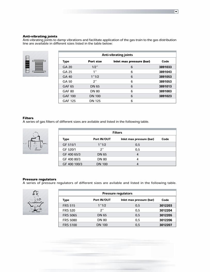
Anti-vibrating jointsAnti-vibrating joints to damp vibrations and facilitate application of the gas train to the gas distributionline are available in different sizes listed in the table below:
Filters
GF 515/1GF 520/1GF 400 65/3GF 400 80/3GF 400 100/3
Type Code
Pressure regulators
FRS 515FRS 520FRS 5065FRS 5080FRS 5100
Type Code30122033012204301220530122063012207
FiltersA series of gas filters of different sizes are avilable and listed in the following table.
Pressure regulatorsA series of pressure regulators of different sizes are avilable and listed in the following table.
Anti-vibrating joints
GA 20GA 25GA 40GA 50GAF 65GAF 80GAF 100GAF 125
Type Code3891033389104338910533891053389101338910033891023
1/2”1”1”1/22”
DN 65DN 80
DN 100DN 125
Port size66666666
Inlet max pressure (bar)
1”1/22”
DN 65DN 80DN 100
Port IN/OUT0,50,5444
Inlet max pressure (bar)
1”1/22”DN 65DN 80
DN 100
Port IN/OUT0,50,50,50,50,5
Inlet max pressure (bar)
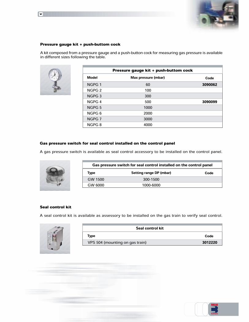
Pressure gauge kit + push-buttom cockA kit composed from a pressure gauge and a push-button cock for measuring gas pressure is availablein different sizes following the table.
Gas pressure switch for seal control installed on the control panelA gas pressure switch is available as seal control accessory to be installed on the control panel.
CodeType3012220
Seal control kitA seal control kit is available as assessory to be installed on the gas train to verify seal control.
CodeType Setting range DP (mbar)Gas pressure switch for seal control installed on the control panel
Seal control kitVPS 504 (mounting on gas train)
GW 1500GW 6000300-15001000-6000
Pressure gauge kit + push-buttom cockCodeModel
3090062
3090099
Max pressure (mbar)NGPG 1NGPG 2NGPG 3NGPG 4NGPG 5NGPG 6NGPG 7NGPG 8
601003005001000200030004000

RIELLO S.p.A. - Via degli Alpini, 1 - 37045 LEGNAGO (VR) ItalyTel. ++39.0442630111 - Fax ++39.044221980Internet: http://www.rielloburners.com - E-mail: [email protected] 9001 Cert. n. 0061Since the Company is constantly engaged in the production improvement, the aesthetic anddimensional features, the technical data, the equipment and the accessories can be changed.This document contains confidential and proprietary information of RIELLO S.p.A.Unless authorised, this information shall not be divulged, nor duplicated in whole or in part.
Line
agra
fica