Industrial Motherboard - newdata.aaeon.com.tw
53
Industrial Motherboard ATX-H310A
Transcript of Industrial Motherboard - newdata.aaeon.com.tw

Indus
trial
Mothe
rboa
rd
ATX-H310A
ii
E16949First EditionJuly 2020
Copyright Notice
This document is copyrighted, 2020. All rights are reserved. The original manufacturer reserves the right to make improvements to the products described in this manual at any time without notice.
No part of this manual may be reproduced, copied, translated, or transmitted in any form or by any means without the prior written permission of the original manufacturer. Information provided in this manual is intended to be accurate and reliable. However, the original manufacturer assumes no responsibility for its use, or for any infringements upon the rights of third parties that may result from its use.The material in this document is for product information only and is subject to change without notice. While reasonable efforts have been made in the preparation of this document to assure its accuracy, the original manufacturer assumes no liabilities resulting from errors or omissions in this document, or from the use of the information contained herein.
The original manufacturer reserves the right to make changes in the product design without notice to its users.
Acknowledgments
All other products’ name or trademarks are properties of their respective owners.
• AMI is a trademark of American Megatrends Inc.• Intel®, Core™ are trademarks of Intel® Corporation.• Microsoft Windows® is a registered trademark of Microsoft Corp.• IBM, PC/AT, PS/2, and VGA are trademarks of International Business
Machines Corporation.
The original manufacturer reserves the right to make changes in the product design without notice to its users.
All other product names or trademarks are properties of their respective owners.

iii
Contents
Chapter 1 Product overview1.1 Package contents ......................................................................... 1-11.2 Features ........................................................................................ 1-11.3 Specifications ............................................................................... 1-2
Chapter 2 Motherboard information2.1 Before you proceed ..................................................................... 2-12.2 Motherboard layout ...................................................................... 2-22.3 Screw size ..................................................................................... 2-4
2.3.1 Component side .............................................................. 2-42.3.2 Solder side ...................................................................... 2-5
2.4 Central Processing Unit (CPU) ................................................... 2-62.4.1 Installing the CPU ........................................................... 2-72.4.2 CPU heatsink and fan assembly installation ................... 2-8
2.5 System memory ......................................................................... 2-102.5.1 Installing a DIMM .......................................................... 2-10
2.6 Jumpers/Slots ............................................................................ 2-122.7 Connectors ................................................................................. 2-17
2.7.1 Rear panel connectors .................................................. 2-172.7.2 Internal connectors ....................................................... 2-19
Chapter 3 BIOS setup3.1 BIOS setup program .................................................................... 3-1
3.1.1 BIOS menu screen .......................................................... 3-23.1.2 Menu bar ......................................................................... 3-2
3.2 Main menu .................................................................................... 3-23.2.1 System Date [Day MM/DD/YYYY] .................................. 3-23.2.2 System Time [HH:MM:SS] .............................................. 3-2
3.3 Advanced menu ........................................................................... 3-33.3.1 CPUConfiguration .......................................................... 3-33.3.2 SATAConfiguration ........................................................ 3-33.3.3 USBConfiguration .......................................................... 3-43.3.4 Hardware Monitor ........................................................... 3-53.3.5 SIOConfiguration ......................................................... 3-113.3.6 PCH-FWConfiguration ................................................. 3-133.3.7 Power Management ...................................................... 3-133.3.8 DigitalIOPortConfiguration ......................................... 3-14

iv
3.4 Chipset menu ............................................................................. 3-153.4.1 SystemAgent(SA)Configuration ................................. 3-153.4.2 PCH-IOConfiguration ................................................... 3-15
3.5 Security menu ............................................................................ 3-163.5.1 Administrator Password ................................................ 3-163.5.2 User Password .............................................................. 3-16
3.6 Boot menu .................................................................................. 3-173.6.1 BootConfiguration ........................................................ 3-173.6.2 FIXED BOOT ORDER Priorities .................................. 3-17
3.7 Save & Exit menu ....................................................................... 3-18
Appendix A-1Notices .......................................................................................................A-1
1-1Chapter 1: Product overview
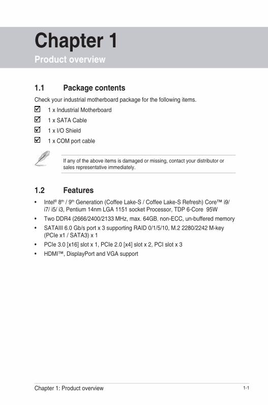
1.1 Package contentsCheck your industrial motherboard package for the following items.
1 x Industrial Motherboard
1 x SATA Cable
1 x I/O Shield
1 x COM port cable
If any of the above items is damaged or missing, contact your distributor or sales representative immediately.
1.2 Features• Intel® 8th / 9th Generation (Coffee Lake-S / Coffee Lake-S Refresh) Core™ i9/
i7/ i5/ i3, Pentium 14nm LGA 1151 socket Processor, TDP 6-Core 95W• Two DDR4 (2666/2400/2133 MHz, max. 64GB, non-ECC, un-buffered memory• SATAIII 6.0 Gb/s port x 3 supporting RAID 0/1/5/10, M.2 2280/2242 M-key
(PCIe x1 / SATA3) x 1• PCIe 3.0 [x16] slot x 1, PCIe 2.0 [x4] slot x 2, PCI slot x 3• HDMI™, DisplayPort and VGA support
Chapter 1Product overview
ATX-H310A1-2
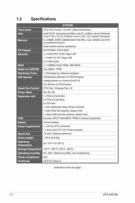
1.3 SpecificationsSYSTEM
Form factor ATX Form Factor, 12”x9.6” (305mmx244mm)
CPU Intel® 8th/9th Generation(Coffee Lake-S, Coffee Lake-S Refresh) Core™ i9/ i7/ i5 /i3, Pentium 14nm LGA 1151 socket Processor
Memory 2 x DIMM, DDR4 (2666/2400/2133 MHz, max. 64GB) non-ECC, un-buffered memory
Dual channel memory architecture
I/O Chipset NCT6793D+ F81216HD
Ethernet 1 x Intel® PHY i219V Giga LAN
1 x Intel® i211AT Giga LAN
2 x RJ45 ports
BIOS 1 x 128Mbit Flash ROM, AMI BIOS
Wake on LAN/PXE Yes (WOL / PXE)
Watchdog Timer 1~255 steps by software program
H/W Monitor Temperature Monitor on CPU/Chassis
Voltage Monitor on Vcore/5V/3.3V/12V
Fan Monitor on CPU/Chassis
Smart Fan Control CPU Fan / Chassis Fan x 2
Power State S3, S4, S5
Expansion slot 1 x PCIe 3.0 [x16] Slot
2 x PCIe 2.0 [x4] Slots
3 x PCI slots
1 x M.2 2280/2242 M-key (PCIex1/SATA3)
1 x Mini PCIe Slot (optional, default: N/A)
1 x Micro SIM card Slot (optional, default: N/A)
TPM Nuvoton NPCT750AABYX TPM2.0 onboard (optional)
Battery Lithium battery
Power requirement 1 x 24-pin ATX connector
1 x 8-pin (2x4) ATX 12V Power connector
Board size 12”x9.6” (305mmx244mm)
Gross weight 1.76 lb (0.8 Kg)
Operating temperature
32~131°F (0~55°C)
Storage temperature -40°F ~185°F (-40°C ~85°C)
Operating humidity 0%~90% relative humidity, non-condensing
Power compliance N/A
Certificate CE/FCC Class A
(continued on the next page)

1-3Chapter 1: Product overview
DISPLAY
Chipset Intel® Graphics Media Accelerator
DisplayPort Up to 4096 x 2160 @ 24 Hz / 3840 x 2160 @ 60 Hz, with Digital Audio
HDMI™ Up to 4096 x 2160 @ 30 Hz
VGA Up to 1920 x 1200 @ 60 Hz (via IT6516B)
Back I/O portsAudio 3 x Audio Jack: Line-in, Mic-in, Line-out
Ethernet 2 x RJ-45 ports
USB 2 x USB 3.2 Gen 1 ports (5 Gbps)
4 x USB 2.0 ports
PS/2 N/A
Serial port 1 x RS-232/422/485 (COM1, supports 5V/12V/RI optional)
Display 1 x DisplayPort port
1 x VGA port
1 x HDMI™ port
Internal I/O connectorsStorage 3 x SATA III (6.0Gb/s) ports support RAID 0/1/5/10
1 x M.2 2280/2242 M-key (PCIex1 / SATA3)
Serial port 5 x RS-232 headers
USB 1 x USB 3.2 Gen 1 header supports additional 2 USB ports
1 x USB 2.0 Type A (vertical) port
Audio 1 x speaker header (Line-out)
1 x AAFP header
Fan 1 x CPU Fan header (4-pin)
2 x Chassis Fan headers (4-pin)
DIO 1 x 8-bit Digital I/O interface (In/Out programmable)
Others 1 x Chassis Intrusion header
1 x AT/ATX mode select jumper
1 x Front panel header
1 x Clear CMOS jumper
1 x 3-pin ME lock header
Others
OS Support Windows® 10 64 bit
Linux Ubuntu 64 bit (18.04.3 / Kernal 5)
NOTE: Specificationsaresubjecttochangewithoutnotice.

ATX-H310A1-4
2-1Chapter 2: Motherboard information
Chapter 2Motherboard information
2.1 Before you proceedTake note of the following precautions before you install motherboard components or change any motherboard settings.
CAUTION!
• Unplug the power cord from the wall socket before touching any component.
• Before handling components, use a grounded wrist strap or touch a safely grounded object or a metal object, such as the power supply case, to avoid damaging them due to static electricity.
• Hold components by the edges to avoid touching the ICs on them.
• Whenever you uninstall any component, place it on a grounded antistatic pad or in the bag that came with the component.
• Before you install or remove any component, ensure that the ATX power supply is switched off or the power cord is detached from the power supply. Failure to do so may cause severe damage to the motherboard, peripherals, or components.

ATX-H310A2-2
ATX-H310A
PCIEX16_1
22422280
M2_
TYP
E_M
1
MIN
I_C
AR
D1
AAFP
PCIEX4_1
PCIEX4_2
PCI1
SIM1
PCI2
PCI3
F_PANEL
DIS_ME CLRTC1ATX_AT
CHASSIS
EA
TX_P
WR
1
CPU_FAN1
CHA_FAN1
CHA_FAN2
BATTERY1
SuperI/O
ALC887
ASM1442K
LGA1151
Intel®H310
Intel® i211AT
Intel® PHY i219V
DD
R4
DIM
M_A
1* (6
4bit,
288
-pin
mod
ule)
DD
R4
DIM
M_B
1* (6
4bit,
288
-pin
mod
ule)
SATA6G_1
SATA6G_3
SATA6G_2
SPI_1
AUDIO
USB20_78
DP1
HDMI1
LAN2_USB3_56
LAN1_USB3_12
24.4cm(9.6in)
128MbBIOS
EATX_PWR2
USB20_9
CO
M6
CO
M5
ASM1083
CO
M4
CO
M3
DIO COM2AMP_CON1
LED_5VSBLED_5V
M2_SSD_LED1
30.5
cm(1
2in)
USB3_34
DEBUG
BZ1
VG
A
COM1_V1
J3
J2
J4
J1
CO
M1
342 31 5 6
7
2
9
8
13 31415 10111219
20
1718 7 16
22
21
2.2 Motherboard layout
Place this side towards the rear of the chassis
NOTE: Place nine screws into the holes indicated by circles to secure the motherboard to the chassis.
CAUTION! Do not overtighten the screws! Doing so can damage the motherboard.

2-3Chapter 2: Motherboard information
Connectors/Jumpers/Slots Page1. USB2.0 port (USB20_9) 2-252. ATX power connectors (24-pin EATX_PWR1, 8-pin EATX_PWR2) 2-193. CPU and chassis fan headers (4-pin CPU_FAN1, 4-pin CHA_FAN1~2) 2-204. Intel® LGA1151 CPU socket 2-65. M.2 M-Key slot 2-246. DDR4 DIMM slots 2-107. COM Port headers (10-1 pin COM2~6) 2-238. BIOS programmable header (8-pin SPI_1) 2-199. SATA 6.0Gb/s ports (7-pin SATA6G_1~3) 2-2210. System panel header (10-1 pin F_PANEL) 2-2111. Chassis intrusion header (4-1 pin CHASSIS) 2-1412. USB 3.2 Gen 1 header (USB3_34) 2-2513. Clear RTC RAM (CLRTC1) 2-1214. Intel® ME Jumper (3-pin DIS_ME) 2-1515. AT/ATX mode jumper (3-pin ATX_AT) 2-1316. Mini PCIe slot 2-1517. Digital I/O header (10-pin DIO1) 2-2418. Front Panel Audio header (10-1 pin AAFP) 2-2219. Audioamplifierconnector(4-pinAMP_CON1) 2-2020. Micro SIM card slot 2-1621. COM1 Ring/+5V/+12V selection (COM1_V1) 2-1422. COM1 RS422/RS485 terminator (2-pin J1~4) 2-13

ATX-H310A2-4
2.3 Screw size2.3.1 Component side
304.80
243.84
161.01
201.65
260.05
280.37
27.0519.64
48.13
69.22
90.30
148.96
0.00
179.94
199.24
240.28
45.45
0.00
150.12
304.80
0.00
35.52
232.96
150.12
7.06
77.04
147.07
228.07
211.06
218.97
237.53
173.61
129.29
77.22
41.28
10.12
221.97
238.36
210.97
197.61
83.03
194.56
5.97
126.81
153.26
126.87
8.75
29.32
51.32
80.92
111.02
132.22
35.68
55.82
85.25
75.3877.22
74.55
66.5569.22
128.72
239.73
107.52
216.03
301.24
300.97
301.24
232.97
294.51
299.97
300.97
299.97
299.97
25.47
12.04
10.9111.84
5.85
16.6822.11
10.49
42.7748.09
137.03
79.25
49.59
31.20
19.59
156.08
165.23
174.37
190.63
214.74
222.25
5.25

2-5Chapter 2: Motherboard information
2.3.2 Solder side
243.84
33.02
10.16
89.31
126.81
108.81
144.81
165.10
164.31165.10
237.49 237.49
0.00
195.23
151.99
16.510.00
140.97
298.45
258.66
183.65
247.58
186.56
183.65
258.66
298.45
140.97
16.51
94.99
125.49
161.55
51.69

ATX-H310A2-6
2.4 Central Processing Unit (CPU)The motherboard comes with a surface mount LGA1151 socket designed for the Intel® 8th / 9th Generation(Coffee Lake-S / Coffee Lake-S Refresh) Core™ i9/ i7/ i5/ i3, Pentium 14nm LGA 1151 socket Processor.
LGA1151
IMPORTANT: Unplug all power cables before installing the CPU.
CAUTION!
• Upon purchase of the motherboard, ensure that the PnP cap is on the socket and the socket contacts are not bent. Contact your retailer immediately if the PnP cap is missing, or if you see any damage to the PnP cap/socket contacts/motherboard components. The manufacturer will shoulder the cost of repair only if the damage is shipment/transit-related.
• Keep the cap after installing the motherboard. The manufacturer will process Return Merchandise Authorization (RMA) requests only if the motherboard comes with the cap on the LGA1151 socket.
• The product warranty does not cover damage to the socket contacts resulting from incorrect CPU installation/removal, or misplacement/loss/incorrect removal of the PnP cap.

2-7Chapter 2: Motherboard information
2.4.1 Installing the CPU
1
A
B
2 3
CAUTION! Ensure that you install the correct CPU designed for LGA 1151 only. DO NOT install a CPU designed for LGA1155 and LGA1156 sockets on the LGA1151 socket.
A
B
C4 5

ATX-H310A2-8
2.4.2 CPU heatsink and fan assembly installation
CAUTION! Apply the Thermal Interface Material to the CPU heatsink and CPU before you install the heatsink and fan if necessary.
To install the CPU heatsink and fan assembly
B
A
A
B
1 2
3 4

2-9Chapter 2: Motherboard information
A
BB
A
To uninstall the CPU heatsink and fan assembly
2
1

ATX-H310A2-10
2.5 System memoryThis motherboard comes with two Double Data Rate 4 (DDR4) Dual Inline Memory Module (DIMM) sockets. A DDR4 module is notched differently from a DDR, DDR2, or DDR3 module. DO NOT install a DDR, DDR2, or DDR3 memory module to the DDR4 slot.
According to Intel® CPU spec, DIMM voltage below 1.2 V is recommended to protect the CPU.
DIM
M_A
1*D
IMM
_B1*
2.5.1 Installing a DIMM
1
2

2-11Chapter 2: Motherboard information
3
To remove a DIMM
A
B
ATX-H310A2-12
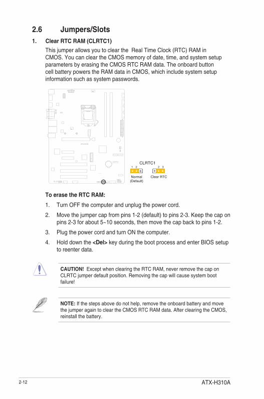
2.6 Jumpers/Slots1. Clear RTC RAM (CLRTC1)
This jumper allows you to clear the Real Time Clock (RTC) RAM in CMOS. You can clear the CMOS memory of date, time, and system setup parameters by erasing the CMOS RTC RAM data. The onboard button cell battery powers the RAM data in CMOS, which include system setup information such as system passwords.
To erase the RTC RAM:
1. Turn OFF the computer and unplug the power cord.
2. Move the jumper cap from pins 1-2 (default) to pins 2-3. Keep the cap on pins 2-3 for about 5~10 seconds, then move the cap back to pins 1-2.
3. Plug the power cord and turn ON the computer.
4. Hold down the <Del> key during the boot process and enter BIOS setup to reenter data.
CAUTION! Except when clearing the RTC RAM, never remove the cap on CLRTC jumper default position. Removing the cap will cause system boot failure!
NOTE: If the steps above do not help, remove the onboard battery and move the jumper again to clear the CMOS RTC RAM data. After clearing the CMOS, reinstall the battery.
1 2 2 3
Normal(Default)
Clear RTC
CLRTC1

2-13Chapter 2: Motherboard information
RS232 RS485/RS422 with terminator (Default)
J3J1J2J4
2. COM1 RS422/RS485 terminator (2-pin J1~4)
3. AT/ATX Mode selection (2-pin ATX_AT)
Pins
1-2 (Default) ATX mode
2-3 AT mode
21 2 3
ATX mode(Default)
AT mode
ATX_AT
NOTE: Jumper setting of ATX_AT should be consistent with the setting of Power Mode in BIOS. Refer to section 3.3.7 Power Management in Chapter 3.

ATX-H310A2-14
4. Chassis intrusion header (4-1 pin CHASSIS)This header is for a chassis-mounted intrusion detection sensor or switch. Connect one end of the chassis intrusion sensor or switch cable to this connector. The chassis intrusion sensor or switch sends a high-level signal to this connector when a chassis component is removed or replaced. The signal is then generated as a chassis intrusion event.By default, the pin labeled “Chassis Signal” and “Ground” are shorted with a jumper cap. Remove the jumper caps only when you intend to use the chassis intrusion detection feature.
PIN1
+5V
SB
_MB
Cha
ssis
Sig
nal
GN
D
CHASSIS
COM1_V1
12
34
56
+12V +5V Ring(Default)
5. COM1 Ring/+5V/+12V selector (6-pin COM1_V1)
Setting Pins
+12V 1-2
+5V 3-4
Ring (Default) 5-6

2-15Chapter 2: Motherboard information
6. Intel® ME Jumper (3-pin DIS_ME)This jumper allows you to force the Intel® Management Engine (ME) to boot from recovery mode when ME becomes corrupted.
2 2 3
ME Enable(Default)
ME Disable
DIS_ME1
7. Mini PCIe slotThis slot allows you to install a mini PCIe module into your motherboard.
MINI_CARD1

ATX-H310A2-16
8. Micro SIM card slotThis slot allows you to install a Micro SIM card.
SIM1

2-17Chapter 2: Motherboard information
2.7 Connectors2.7.1 Rear panel connectors
2 3 4 5
9 1 106 87
1
1. USB 2.0 ports. These 4-pin Universal Serial Bus (USB) ports are for USB 2.0 devices.
2. Serial port connector (10-1 pin COM). This port connects a modem, or otherdevicesthatconformwithserialspecification.
3. LAN1~2 (RJ-45) ports. These ports allow Gigabit connection to a Local Area Network (LAN) through a network hub. Refer to the table below for the LAN port LED indications.
LAN port
Speed LEDActivity Link LEDACT/LINK LED SPEED LED
Status Description Status DescriptionOFF No link OFF 10 Mbps connectionORANGE Linked ORANGE 100 Mbps connectionBLINKING Data activity GREEN 1 Gbps connection
LAN port LED indications
4. Line In port (light blue). This port connects to the tape, CD, DVD player, or other audio sources.
5. Line Out port (lime). This port connects to a headphone or a speaker. In the4.1,5.1and7.1-channelconfigurations,thefunctionofthisportbecomesFront Speaker Out.
6. DisplayPort. This port is for a DisplayPort-compatible device.
7. HDMI™ port.ThisportisforaHigh-DefinitionMultimediaInterface(HDMI™)connector, and is HDCP compliant allowing playback of HD DVD, Blu-ray, and other protected content.
8. Video Graphics Adapter (VGA) port. This 15-pin port is for a VGA monitor or other VGA-compatible devices.

ATX-H310A2-18
9. USB 3.2 Gen 1 ports (Blue, Type-A). These 9-pin Universal Serial Bus (USB) ports connect to USB 3.2 Gen 1 devices.
NOTES:
• We strongly recommend that you connect USB 3.2 Gen 1 devices to USB 3.2 Gen 1 ports for a faster and better performance from your USB 3.2 Gen 1 devices.
• Due to the design of the Intel® 300 series chipset, all USB devices connected to the USB 2.0 and USB 3.2 Gen 1 ports are controlled by the xHCIcontroller.SomelegacyUSBdevicesmustupdatetheirfirmwareforbetter compatibility.
10. Microphone port (pink). This port connects to a microphone.

2-19Chapter 2: Motherboard information
2.7.2 Internal connectors
IMPORTANT:
• Forafullyconfiguredsystem,werecommendthatyouuseapowersupplyunit(PSU)thatcomplieswithATX12VSpecification2.0(orlaterversion)and provides a minimum power of 330W.
• We recommend that you use a PSU with higher power output when configuringasystemwithmorepower-consumingdevices.Thesystemmay become unstable or may not boot up if the power is inadequate.
1. ATX power connectors (24-pin EATX_PWR1, 8-pin EATX_PWR2)These connectors are for ATX power supply plugs. The power supply plugs aredesignedtofittheseconnectorsinonlyoneorientation.Findtheproperorientationandpushdownfirmlyuntiltheconnectorscompletelyfit.
A
PIN 1
GND+5 Volts+5 Volts+5 Volts-5 VoltsGNDGNDGNDPSON#GND-12 Volts+3 Volts
+3 Volts+12 Volts+12 Volts
+5V StandbyPower OK
GND+5 Volts
GND+5 Volts
GND+3 Volts+3 Volts
B
BA
EATX_PWR1
GN
DG
ND
GN
DG
ND
+12V
DC
+12V
DC
+12V
DC
+12V
DC
PIN 1
EATX_PWR2
PIN 1
SPI_1GNDS_BIOS_CLK_1QS_BIOS_MOSI_1Q(NC)
+3V_SPIS_BIOS_CS0#_1QS_BIOS_MISO_1Q
(NC)
2. BIOS programmable header (8-pin SPI_1)Use this header to flash the BIOS ROM.

ATX-H310A2-20
CAUTION: Do not forget to connect the fan cables to the fan headers. Insufficientairflowinsidethesystemmaydamagethemotherboardcomponents. These are not jumpers! Do not place jumper caps on the fan headers!
3. CPU and chassis fan headers (4-pin CPU_FAN1, 4-pin CHA_FAN1~2)Connect the fan cables to the fan headers on the motherboard, ensuring that the black wire of each cable matches the ground pin of the header.
A
B
C
ABC
CPU_FAN1CHA_FAN1CHA_FAN2
GN
D+1
2VS
EN
SE
PW
M
4. Audioamplifierconnector(4-pinAMP_CON1)
Thisconnectorisforaninternalstereoamplifierspeakerssupport(2W/4via WtoB header).
PIN 1
RO
UT
PR
OU
TN
LOU
TN
LOU
TP
AMP_CON1

2-21Chapter 2: Motherboard information
5. System panel header (10-1 pin F_PANEL)This header supports several chassis-mounted functions.
• System power LED (2-pin P_LED)This 2-pin header is for the system power LED. Connect the chassis power LED cable to this connector. The system power LED lights up when you turn on the system power, and turns off when the system is in ACPI-S3/S4/S5 mode by default.
• Hard disk drive activity LED (2-pin +HDLED)This 2-pin header is for the HDD Activity LED. Connect the HDD Activity LED cable to this connector. The HDD LED lights up or flashes when data is read from or written to the HDD.
• ATX power button/soft-off button (2-pin PWRBTN)This 2-pin header is for the system power button. Pressing the power button turns the system on, puts the system in sleep, or soft-off mode depending on the operating system setting. Pressing the power switch for more than four seconds while the system is ON turns the system OFF.
• Reset button (2-pin RESET)This 2-pin header is for the chassis-mounted reset button for system reboot without turning off the system power.
PIN 1
PWR_BTN
P_L
ED
+P
_LE
D-
PW
RB
TN#
GN
D
HD
D_L
ED
+H
DD
_LE
D-
GN
DR
STC
ON
#_P
AN
EL
(NC
)
F_PANELPWR LED
HDD_LED RESET

ATX-H310A2-22
6. SATA 6.0Gb/s connector (7-pin SATA6G_1~3)These connectors connect to Serial ATA 6.0 Gb/s hard disk drives via Serial ATA 6.0 Gb/s signal cables.
NOTE: When using hot-plug and NCQ, set the SATA Mode Selection item in the BIOS to [AHCI]. See section 3.3.2SATAConfiguration for details.
A
C
B
A
B
C
SATA6G_1SATA6G_2
SATA6G_3
GN
DR
SA
TA_T
XP
RS
ATA
_TX
NG
ND
RS
ATA
_RX
NR
SA
TA_R
XP
GN
D
GN
DR
SA
TA_R
XP
RS
ATA
_RX
NG
ND
RS
ATA
_TX
NR
SA
TA_T
XP
GN
D
7. Front panel audio header (10-1 pin AAFP)
This header is for a chassis-mounted front panel audio I/O module that supports HD audio standard. Connect one end of the front panel audio I/O module cable to this header.
AAFP
GN
DN
CA
_JD
_MIC
2
A_J
D_L
INE
2
A_M
IC2_
LA
_MIC
2_R
A_L
INE
2_R
A_J
D_F
RO
NT
A_L
INE
2_L
PIN 1
• Werecommendthatyouconnectahigh-definitionfrontpanelaudiomoduletothisheadertoavailofthemotherboard’shigh-definitionaudiocapability.
• Ifyouwanttoconnectahigh-definitionfrontpanelaudiomoduletothisheader,settheFront Panel Type item in the BIOS setup to [HD Audio]. By default, this header is set to [HD Audio].

2-23Chapter 2: Motherboard information
8. COM Port headers (10-1 pin COM2~COM6)These headers are for serial (COM) ports. Connect the serial port module cable to any of these headers, then install the module to a slot opening at the back of the system chassis.
NOTES:
• The COM module is purchased separately.
• COM1 also supports RS-232 / RS-422 / RS-485. See the table below and section 3.3.5SIOConfiguration for details.
A A
B
C
D
E
B
C
D
PIN 1
PIN 1
DC
D#
TXD
GN
DR
TS#
Rin
g
RingRTS#GNDTXDDCD#
RX
DD
TR#
DS
R#
CTS
#(N
C)
(NC)CTS#DSR#DTR#RXD
COM2
COM6
COM5
COM4
COM3
E
Pin SignalSignal PinPin Signal
1 DCD# (422TXD-/485DATA-) 2 RXD (422TXD+/485DATA+)
3 TXD (422RXD+) 4 DTR# (422RXD-)
5 GND 6 DSR#
7 RTS# 8 CTS#
9 RI/+5V/+12V 10 N.C.

ATX-H310A2-24
9. M.2 M-key socketThe M.2 M-key socket allows you to install an M.2 SSD module.
M2_TYPE_M1
NOTES:
• The M.2 module is purchased separately.
• The M.2 M-key slot supports PCIe SSD (Ideal Speed:800MB/s) and 2280/2242 storage devices.
10. Digital I/O header (10-pin DIO1)This header includes 8 I/O lines (In/Out programmable). All of the Digital I/O lines are programmable and each I/O pin can be individually programmed to support various devices.
PIN 1
DIO
DIO
_P#1
(In_
1)D
IO_P
#3 (I
n_3)
DIO
_P#5
(Out
_1)
DIO
_P#7
(Out
_3)
+5V
DIO
_P#2
(In_
2)D
IO_P
#4 (I
n_4)
DIO
_P#6
(Out
_2)
DIO
_P#8
(Out
_4)
GN
D
2-25Chapter 2: Motherboard information
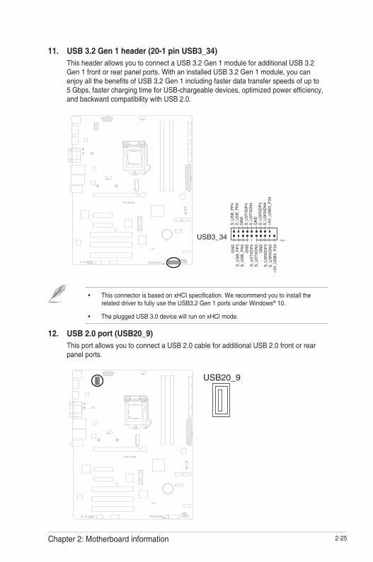
11. USB 3.2 Gen 1 header (20-1 pin USB3_34)This header allows you to connect a USB 3.2 Gen 1 module for additional USB 3.2 Gen 1 front or rear panel ports. With an installed USB 3.2 Gen 1 module, you can enjoyallthebenefitsofUSB3.2Gen1includingfasterdatatransferspeedsofupto5Gbps,fasterchargingtimeforUSB-chargeabledevices,optimizedpowerefficiency,and backward compatibility with USB 2.0.
USB20_9
• ThisconnectorisbasedonxHCIspecification.Werecommendyoutoinstalltherelated driver to fully use the USB3.2 Gen 1 ports under Windows® 10.
• The plugged USB 3.0 device will run on xHCI mode.
12. USB 2.0 port (USB20_9)This port allows you to connect a USB 2.0 cable for additional USB 2.0 front or rear panel ports.
USB3_34G
ND
S_U
SB
_PP
3S
_US
B_P
N3
GN
DS
_U3T
XD
P3
S_U
3TX
DN
3G
ND
S_U
3RX
DP
3S
_U3R
XD
N3
+5V
_US
B3_
P34
PIN 1
S_U
SB
_PP
4S
_US
B_P
N4
GN
DS
_U3T
XD
P4
S_U
3TX
DN
4G
ND
S_U
3RX
DP
4S
_U3R
XD
N4
+5V
_US
B3_
P34

3-1Chapter 3: BIOS setup
Chapter 3BIOS setup
3.1 BIOS setup programUsetheBIOSSetupprogramtoconfigureitsparameters.TheBIOSscreensinclude navigation keys and brief online help to guide you in using the BIOS Setup program.
Entering BIOS Setup at startupTo enter BIOS Setup at startup:Press <Delete> during the Power-On Self Test (POST). If you do not press <Delete>, POST continues with its routine.
Entering BIOS Setup after POSTTo enter BIOS Setup after POST:• Press <Ctrl>+<Alt>+<Del> simultaneously. • Press the reset button on the system chassis. • Press the power button to turn the system off then back on. Do this option only
ifyoufailedtoenterBIOSSetupusingthefirsttwooptions.
Using the power button, reset button, or the <Ctrl>+<Alt>+<Del> keys to reboot a running operating system can cause damage to your data or system. Always shut down the system properly from the operating system.
IMPORTANT:
• The default BIOS settings for this motherboard apply to most working conditions and ensures optimal performance. If the system becomes unstable after changing any BIOS settings, load the default settings to regain system stability. Select the option Restore Defaults under the Save & Exit Menu. See section 3.7 Save & Exit.
• The BIOS setup screens shown in this section are for reference purposes only, and may not exactly match what you see on your screen.

3-2 ATX-H310A
3.1.2 Menu bar
The menu bar on top of the screen has the following main items:
Main Forchangingthebasicsystemconfiguration.
Advanced For changing the advanced system settings.
Chipset For viewing and changing chipset settings.
Security For setting up BIOS security settings.
Boot Forchangingthesystembootconfiguration.
Save & Exit For selecting the exit options and loading default settings.
To select an item on the menu bar, press the right or left arrow key on the keyboard until the desired item is highlighted.
3.1.1 BIOS menu screen
3.2 Main menuThe Main menu provides you an overview of the basic system information, and allows you to set the system date, time, language, and security settings.
3.2.1 System Date [Day MM/DD/YYYY]
Allows you to set the system date.
3.2.2 System Time [HH:MM:SS]
Allows you to set the system time.

3-3Chapter 3: BIOS setup
3.3 Advanced menuThe Advanced menu items allow you to change the settings for the CPU and other system devices.
Be cautious when changing the settings of the Advanced menu items. Incorrect fieldvaluescancausethesystemtomalfunction.
Case Open Warning [Disabled]Allowsyoutoenableordisablethecaseopendetectingfunction.Configurationoptions: [Disable] [Enabled] [Clear]
3.3.1 CPUConfiguration
The items in this menu show CPU-related information the BIOS automatically detects.
The items shown in the submenu may be different depending on the type of CPU installed.
Hyper-threading [Enabled]The Intel Hyper-Threading Technology allows a hyper-threading processor to appear as two logical processors to the operating system, allowing the operating system to schedule two threads or processes simultaneously.[Enabled] Two threads per activated core are enabled.[Disabled] Only one thread per activated core is enabled.
Intel (VMX) Virtualization Technology [Enabled][Enabled] Allows a hardware platform to run multiple operating
systems separately and simultaneously, enabling one system to virtually function as several systems.
[Disabled] Disables this function.
3.3.2 SATAConfiguration
The BIOS automatically detects the presence of SATA devices. The Serial ATA Ports listed will display Empty if there are no Serial devices connected to the ports.
SATA Controller(s) [Enabled]Configurationoptions:[Enabled][Disabled].
The following items appear only when you set SATA Controller(s) to [Enabled].

3-4 ATX-H310A
SATA Mode Selection [AHCI]AllowsyoutosettheSATAconfiguration.[AHCI] Set to [AHCI] when you want the SATA hard disk
drives to use the AHCI (Advanced Host Controller Interface). The AHCI allows the onboard storage driver to enable advanced Serial ATA features that increases storage performance on random workloads by allowing the drive to internally optimize the order of commands.
[RAID] Set to [RAID] when you want to create a RAID configurationfromtheSATAharddiskdrives.
Port 0/1/2/3/4 [Enabled] TheseitemsbecomeconfigurablewhenyousettheSATAModeSelectionitem to [AHCI] and [RAID], and allow you to enable/disable the SATA port(s). Configurationoptions:[Disabled][Enabled]
Hot Plug [Disabled]TheseitemsbecomeconfigurablewhenyousettheSATAModeSelectionitemto [AHCI] and [RAID], and allow you to enable/disable SATA Hot Plug Support. Configurationoptions:[Disabled][Enabled]
3.3.3 USBConfiguration
The USB Devices item lists auto-detected values. If no USB device is detected, the item shows None.
Legacy USB Support [Enabled]
[Enabled] Enables the support for USB devices on legacy operating systems (OS).
[Disabled] USB devices are only available when running BIOS Setup.
[Auto] Allows the system to detect the presence of USB devices at startup. If detected, the USB controller legacy mode is enabled. If no USB device is detected, the legacy USB support is disabled.

3-5Chapter 3: BIOS setup
3.3.4 Hardware Monitor
The items in this menu provide you an overview of system status including temperature,fanspeedandvoltage,andallowyoutoconfigurethesmartfan.
SmartFanConfiguration
CPU Smart Fan Control [Enabled]AllowsyoutoenableordisableCPUSmartFanControl.Configurationoptions:[Enabled] [Disabled]
The following sub-items appear only when you set CPU Smart Fan Control to [Enabled].
Fan Control Mode [Smart Fan IV Mode]Configurationoptions:[ManualMode][ThermalCruiseMode][SmartFanIVMode]
The following item appears only when you set Fan Control Mode to [Manual Mode].
PWM/DC Voltage Output [255]Sets the voltage allocated for Fan Control. Input value range: [0~255]
The following items appear only when you set Fan Control Mode to [Thermal Cruise Mode].
Target Temperature [50]Input value range: [0~127]
Tolerance of Temperature [0]Input value range: [0~7]
Fan Out Start-Up Value [127]Input value range: [0~255]
Fan Stop Duty [Down to 0]Selectsfanstopdutymode.Configurationoptions:[Downto0][ToFanOutStop Value]
Fan Out Stop Value [100]The Fan Out value decreases to this value if the temperature reaches below the lowest temperature limit. Input value range: [0~255]
3-6 ATX-H310A
Fan Out Stop Time [60]Determines the amount of time it takes for the Fan Out value to fall from the stop value to zero. Input value range: [0~255]
Critical Temperature [75]Determines the amount of time Fan Out takes to decrease its value by one step. Input value range: [0~255]
Fan Out Step Up Time [10]Determines the amount of time Fan Out takes to increase its value by one step. Input value range: [0~255]
Fan Out Step Down Time [10]Determines the amount of time Fan Out takes to decrease its value by one step in intervals of 0.1 seconds. Input value range: [0~255]
The following items appear only when you set Fan Control Mode to [Smart Fan IV Mode].
Temperature 1 [40] / Temperature 2 [50] / Temperature 3 [60] / Temperature 4 [70] Determines the temperature value for the Smart Fan IV mode.
Fan PWM 1 [150] / Fan PWM 2 [170] / Fan PWM 3 [200] / Fan PWM 4 [220]Determines the amount of Fan PWM value for the Smart Fan IV mode
Tolerance of Temperature [0]Input value range: [0~7]
Critical Temperature [75]Input value range: [0~255]
Critical Temp Tolerance [0]Input value range: [0~7]
Fan Count Step Up [1]Input value range: [0~15]
Fan Count Step Down [1]Input value range: [0~15]

3-7Chapter 3: BIOS setup
Fan Out Step Up Time [10]Determines the amount of time Fan Out takes to increase its value by one step. Input value range: [0~255]
Fan Out Step Down Time [10]Determines the amount of time Fan Out takes to decrease its value by one step in intervals of 0.1 seconds. Input value range: [0~255]
CHA_FAN1 Smart Fan Control [Enabled]AllowsyoutoenableordisableCHA_FAN1SmartFanControl.Configurationoptions: [Enabled] [Disabled]
The following sub-items appear only when you set CHA_FAN1 Smart Fan Control to [Enabled].
Fan Control Mode [SMART FAN IV Mode]Configurationoptions:[ManualMode][ThermalCruiseMode][SMARTFANIV Mode]
The following items appear only when you set Fan Control Mode to [Manual Mode].
PWM/DC Voltage Output [255]
This item appears only when you set the previous item to [Manual Mode] and allows you to set the voltage allocated for Fan Control. Input value range: [0~255]
The following items appear only when you set Fan Control Mode to [Thermal Cruise Mode].
Target Temperature [50]Input value range: [0~127]
Tolerance of Temperature [0]Input value range: [0~7]
Fan Out Start-Up Value [127]Input value range: [0~255]
Fan Stop Duty [To Fan Out Stop Value]Selectsfanstopdutymode.Configurationoptions:[Downto0][ToFanOutStop Value]
3-8 ATX-H310A
Fan Out Stop Value [100]The Fan Out value decreases to this value if the temperature reaches below the lowest temperature limit. Input value range: [0~255]
Fan Out Stop Time [60]Determines the amount of time it takes for the Fan Out value to fall from the stop value to zero. Input value range: [0~255]
Critical Temperature [75]Determines the amount of time Fan Out takes to decrease its value by one step. Input value range: [0~255]
Fan Out Step Up Time [10]Determines the amount of time Fan Out takes to increase its value by one step. Input value range: [0~255]
Fan Out Step Down Time [10]Determines the amount of time Fan Out takes to decrease its value by one step in intervals of 0.1 seconds. Input value range: [0~255]
The following items appear only when you set Fan Control Mode to [SMART FAN IV Mode].
Temperature 1 [40] / Temperature 2 [50] / Temperature 3 [60] / Temperature 4 [70] Determines the temperature value for the Smart Fan IV mode.
Fan PWM 1 [150] / Fan PWM 2 [170] / Fan PWM 3 [200] / Fan PWM 4 [220]Determines the amount of Fan PWM value for the Smart Fan IV mode.
Tolerance of Temperature [0]Input value range: [0~7]
Critical Temperature [75]Input value range: [0~255]
Critical Temp Tolerance [0]Input value range: [0~7]
Fan Count Step Up [1]Input value range: [0~15]

3-9Chapter 3: BIOS setup
Fan Count Step Down [1]Input value range: [0~15]
Fan Out Step Up Time [10]Determines the amount of time Fan Out takes to increase its value by one step. Input value range: [0~255]
Fan Out Step Down Time [10]Determines the amount of time Fan Out takes to decrease its value by one step in intervals of 0.1 seconds. Input value range: [0~255]
CHA_FAN2 Smart Fan Control [Enabled]AllowsyoutoenableordisableCHA_FAN2SmartFanControl.Configurationoptions: [Enabled] [Disabled]
The following sub-items appear only when you set CHA_FAN2 Smart Fan Control to [Enabled].
Fan Control Mode [SMART FAN IV Mode]Configurationoptions:[ManualMode][ThermalCruiseMode][SMARTFANIV Mode]
The following item appears only when you set Fan Control Mode to [Manual Mode].
PWM/DC Voltage Output [255]Sets the voltage allocated for Fan Control. Input value range: [0~255]
The following items appear only when you set Fan Control Mode to [Thermal Cruise Mode].
Target Temperature [50]Input value range: [0~127]
Tolerance of Temperature [0]Input value range: [0~7]
Fan Out Start-Up Value [127]Input value range: [0~255]
Fan Stop Duty [Down to 0]Selectsfanstopdutymode.Configurationoptions:[Downto0][ToFanOutStop Value]

3-10 ATX-H310A
Fan Out Stop Value [100]The Fan Out value decreases to this value if the temperature reaches below the lowest temperature limit. Input value range: [0~255]
Fan Out Stop Time [60]Determines the amount of time it takes for the Fan Out value to fall from the stop value to zero. Input value range: [0~255]
Critical Temperature [75]Determines the amount of time Fan Out takes to decrease its value by one step. Input value range: [0~255]
Fan Out Step Up Time [10]Determines the amount of time Fan Out takes to increase its value by one step. Input value range: [0~255]
Fan Out Step Down Time [10]Determines the amount of time Fan Out takes to decrease its value by one step in intervals of 0.1 seconds. Input value range: [0~255]
The following items appear only when you set Fan Control Mode to [Smart Fan IV Mode].
Temperature 1 [40] / Temperature 2 [50] / Temperature 3 [60] / Temperature 4 [70] Determines the temperature value for the Smart Fan IV mode.
Fan PWM 1 [150] / Fan PWM 2 [170] / Fan PWM 3 [200] / Fan PWM 4 [220]Determines the amount of Fan PWM value for the Smart Fan IV mode
Tolerance of Temperature [0]Input value range: [0~7]
Critical Temperature [75]Input value range: [0~255]
Critical Temp Tolerance [0]Input value range: [0~7]
Fan Count Step Up [1]Input value range: [0~15]

3-11Chapter 3: BIOS setup
Fan Count Step Down [1]Input value range: [0~15]
Fan Out Step Up Time [10]Determines the amount of time Fan Out takes to increase its value by one step. Input value range: [0~255]
Fan Out Step Down Time [10]Determines the amount of time Fan Out takes to decrease its value by one step in intervals of 0.1 seconds. Input value range: [0~255]
3.3.5 SIOConfiguration
TheitemsinthismenuallowyoutoconfigureSuperIOsettings.
[*Active*] Serial Port 1
Use this device [Enabled]Allowsyoutoenableordisablethislogicaldevice.Configurationoptions:[Enabled] [Disabled]
The following two items appear only when you set Use this device to [Enabled].
Possible [Use Automatic Settings]AllowsyoutoselectanoptimalsettingforSuperI/Odevices.Configurationoptions: [Use Automatic Settings] [IO=3F8h; IRQ=4;] [IO=3E8h; IRQ=7]
Mode [RS232]AllowsyoutoselecttheSerialPortmode.Configurationoptions:[RS232][RS422] [RS485]
[*Active*] Serial Port 2
Use this device [Enabled]Allowsyoutoenableordisablethislogicaldevice.Configurationoptions:[Enabled] [Disabled]
Possible [Use Automatic Settings]This item appears only when you set Use this device to [Enabled] and allowsyoutoselectanoptimalsettingforSuperI/Odevices.Configurationoptions: [Use Automatic Settings] [IO=3E8h; IRQ=7] [IO=3F8h; IRQ=4;]

3-12 ATX-H310A
Mode [RS232]AllowsyoutoselecttheSerialPortmode.Configurationoption:[RS232]
[*Active*] Serial Port 3
Use this device [Enabled]Allowsyoutoenableordisablethislogicaldevice.Configurationoptions:[Enabled] [Disabled]
Possible [Use Automatic Settings]This item appears only when you set Use this device to [Enabled] and allowsyoutoselectanoptimalsettingforSuperI/Odevices.Configurationoptions: [Use Automatic Settings] [IO=240h; IRQ=11; DMA] [IO=248h; IRQ=11; DMA] [IO=250h; IRQ=11; DMA] [IO=258h; IRQ=11; DMA]
Mode [RS232]AllowsyoutoselecttheSerialPortmode.Configurationoption:[RS232]
[*Active*] Serial Port 4
Use this device [Enabled]Allowsyoutoenableordisablethislogicaldevice.Configurationoptions:[Enabled] [Disabled]
Possible [Use Automatic Settings]This item appears only when you set Use this device to [Enabled] and allowsyoutoselectanoptimalsettingforSuperI/Odevices.Configurationoptions: [Use Automatic Settings] [IO=248h; IRQ=11; DMA] [IO=240h; IRQ=11; DMA] [IO=250h; IRQ=11; DMA] [IO=258h; IRQ=11; DMA]
Mode [RS232]AllowsyoutoselecttheSerialPortmode.Configurationoption:[RS232]
[*Active*] Serial Port 5
Use this device [Enabled]Allowsyoutoenableordisablethislogicaldevice.Configurationoptions:[Enabled] [Disabled]
Possible [Use Automatic Settings]This item appears only when you set Use this device to [Enabled] and allowsyoutoselectanoptimalsettingforSuperI/Odevices.Configurationoptions: [Use Automatic Settings] [IO=250h; IRQ=11; DMA] [IO=240h; IRQ=11; DMA] [IO=248h; IRQ=11; DMA] [IO=258h; IRQ=11; DMA]

3-13Chapter 3: BIOS setup
Mode [RS232]AllowsyoutoselecttheSerialPortmode.Configurationoption:[RS232]
[*Active*] Serial Port 6
Use this device [Enabled]Allowsyoutoenableordisablethislogicaldevice.Configurationoptions:[Enabled] [Disabled]
Possible [Use Automatic Settings]This item appears only when you set Use this device to [Enabled] and allowsyoutoselectanoptimalsettingforSuperI/Odevices.Configurationoptions: [Use Automatic Settings] [IO=258h; IRQ=11; DMA] [IO=240h; IRQ=11; DMA] [IO=248h; IRQ=3,4,5,6,7,11,12; DMA] [IO=250h; IRQ=3,4,5,6,7,11,12; DMA] [IO=258h; IRQ=3,4,5,6,7,11,12; DMA]
3.3.6 PCH-FWConfiguration
Theitemslistedinthisscreendisplayfirmwarerelatedinformation.
FirmwareUpdateConfiguration
Me FW Image Re-Flash [Disabled]AllowsyoutoenableordisableMefirmwareImageRe-Flashfunction.Configurationoptions:[Disabled][Enabled]
Local FW Update [Enabled]AllowsyoutoenableordisabletheLocalFWUpdatefunction.Configurationoptions: [Disabled] [Enabled]
3.3.7 Power Management
Power Mode [ATX Type]Selectpowersupplymode.Configurationoptions:[ATXType][ATType]
The following items appear when you set Power Mode to [ATX Type].
Restore AC Power Loss [Last State][Last State] The system goes into either off or on state, whatever the system
state was.[Always On] The system goes into on state after an AC power loss.[Always Off] The system goes into off state after an AC power loss.

3-14 ATX-H310A
RI Wake Event [Disabled]EnableordisablesystemtowakeupfromRI#.Configurationoptions:[Enabled][Disabled]
RTC Wake system from S5 [Disabled]
[Disabled] Disables system wake up from S5.
[FixedTime] Thesystemwillwakeupatthespecifiedhr::min::sec.
[DynamicTime] Thesystemwillwakeupatthecurrenttimeplusaspecifiednumber of minutes.
The following items appear when Fixed Time is enabled.
Wake up day/hour/minute/second [0]Specify the values for day/hour/minute/second.
The following item appears when Wake System with Dynamic Time is enabled.
Wake up minute increase [1]Specify the number of minutes added to the current time before waking up system. Input value range: [1~5]
3.3.8 DigitalIOPortConfiguration
TheitemslistedinthisscreenconfigureDigitalIOsettings.
DIO Port1~DIO Port4 [Output]Configurationoptions:[Input][Output]
The following item appears only when you set DIO Port1/2/3/4 to [Output].
Output Level [High]Configurationoptions:[High][Low]
DIO Port5~DIO Port8 [Input]Configurationoptions:[Input][Output]
3-15Chapter 3: BIOS setup
3.4 Chipset menuThe Chipset menu items allow you to change the settings for the chipset.
3.4.1 SystemAgent(SA)Configuration
Max TOLUD [Dynamic]ConfiguresthemaximumvalueofTOLUD.DynamicassignmentwilladjustTOLUDautomatically based on the largest MMIO length of installed graphics controller. Configurationoptions:[Dynamic][1GB][1.25GB]~[3.5GB]
Primary Display [Auto]Allows you to decide which graphics controller to use as the primary boot device. Configurationoptions:[Auto][IGFX][PEG][PCI]
Primary IGFX Boot Display [VBIOS Default]Select the video device which will be activated during POST. This setting has no effect if an external graphics device is present. The secondary boot display selection appears based on your selection and the VGA mode is supported only on primarydisplay.Configurationoptions:[VBIOSDefault][DP][HDMI][VGA]
PCIEX16 Gen Speed [Auto]AllowsyoutoselectthePCIExpressportspeed.Configurationoptions:[Auto][Gen1][Gen2][Gen 3]
3.4.2 PCH-IOConfiguration
HD Audio [Enabled]ThisitemcontrolsthedetectionofHDAudiodevices.Configurationoptions:[Disabled] [Enabled]
PCIEX1_1 Gen Speed [Auto]ConfiguresthespeedofPCIExpressx1slot.Configurationoptions:[Auto][Gen1][Gen2] [Gen3]
PCIEX1_2 Gen Speed [Auto]ConfiguresthespeedofPCIExpressx1slot.Configurationoptions:[Auto][Gen1][Gen2] [Gen3]
PCIEX4_1 Gen Speed [Auto]ConfiguresthespeedofPCIExpressx4slot.Configurationoptions:[Auto][Gen1][Gen2] [Gen3]

3-16 ATX-H310A
3.5 Security menuThe Security menu items allow you to change the system security settings.
3.5.1 Administrator Password
If you have set an administrator password, we recommend that you enter the administrator password for accessing the system. Otherwise, you might be able to seeorchangeonlyselectedfieldsintheBIOSsetupprogram.
To set an administrator password:
1. Select the Administrator Password item and press <Enter>.
2. From the Create New Password box, key in a password, then press <Enter>.
3. Confirmthepasswordwhenprompted.
To change an administrator password:
1. Select the Administrator Password item and press <Enter>.
2. From the Enter Current Password box, key in the current password, then press <Enter>.
3. From the Create New Password box, key in a new password, then press <Enter>.
4. Confirmthepasswordwhenprompted.
To clear the administrator password, follow the same steps as in changing an administratorpassword,butpress<Enter>whenpromptedtocreate/confirmthepassword.
3.5.2 User Password
If you have set a user password, you must enter the user password for accessing the system.
To set a user password:
1. Select the User Password item and press <Enter>.
2. From the Create New Password box, key in a password, then press <Enter>.
3. Confirmthepasswordwhenprompted.

3-17Chapter 3: BIOS setup
To change a user password:
1. Select the User Password item and press <Enter>.
2. From the Enter Current Password box, key in the current password, then press <Enter>.
3. From the Create New Password box, key in a new password, then press <Enter>.
4. Confirmthepasswordwhenprompted.
To clear the user password, follow the same steps as in changing a user password,butpress<Enter>whenpromptedtocreate/confirmthepassword.Afteryou clear the password, the User Password item on top of the screen shows Not Installed.
3.6 Boot menuThe Boot menu items allow you to change the system boot options.
3.6.1 BootConfiguration
Quiet Boot [Enabled]Thisitemenables/disablesQuietBoot.Configurationoptions:[Disabled][Enabled]
Launch PXE ROM [Do not launch]ThisitemcontrolstheexecutionofUEFIandLegacyPXEOpROM.Configurationoptions: [Legacy] [UEFI] [Do not Launch]
3.6.2 FIXED BOOT ORDER Priorities
Boot Option #1~#16 Thisitemallowsyoutosetthesystembootorder.Configurationoptions:[UEFIHard Disk] [UEFI USB Key] [UEFI USB Hard Disk] [UEFI Network] [UEFI USB Lan] [UEFI CD/DVD] [UEFI USB CD/DVD] [UEFI USB Floppy] [Hard Disk] [ USB Key] [USB Hard Disk] [Network] [USB Lan] [CD/DVD] [USB CD/DVD] [USB Floppy][ Disabled]

3-18 ATX-H310A
3.7 Save & Exit menuSave Changes and ResetOnceyouarefinishedmakingyourselections,choosethisoptionfromtheSave& Exit menu to ensure the values you selected are saved. When you select this option,aconfirmationwindowappears.SelectYestosavechangesandreset.
Discard Changes and ExitThis option allows you to exit the Setup program without saving your changes. Whenyouselectthisoptionorifyoupress<Esc>,aconfirmationwindowappears.Select Yes to discard changes and exit.
Restore DefaultsSave or restore User Defaults to all setup options.

ATX-H310A A-1
AppendixNoticesFederal Communications Commission StatementThis device complies with Part 15 of the FCC Rules. Operation is subject to the following two conditions:• This device may not cause harmful interference.• This device must accept any interference received including interference that
may cause undesired operation.This equipment has been tested and found to comply with the limits for a Class A digital device, pursuant to Part 15 of the FCC Rules. These limits are designed to provide reasonable protection against harmful interference in a residential installation. This equipment generates, uses and can radiate radio frequency energy and, if not installed and used in accordance with manufacturer’s instructions, may cause harmful interference to radio communications. However, there is no guarantee that interference will not occur in a particular installation. If this equipment does cause harmful interference to radio or television reception, which can be determined by turning the equipment off and on, the user is encouraged to try to correct the interference by one or more of the following measures:• Reorient or relocate the receiving antenna.• Increase the separation between the equipment and receiver.• Connect the equipment to an outlet on a circuit different from that to which the
receiver is connected.• Consult the dealer or an experienced radio/TV technician for help.
WARNING! The use of shielded cables for connection of the monitor to the graphics card is required to assure compliance with FCC regulations. Changes ormodificationstothisunitnotexpresslyapprovedbythepartyresponsibleforcompliance could void the user’s authority to operate this equipment.
DO NOT throw the motherboard in municipal waste. This product has been designed to enable proper reuse of parts and recycling. This symbol of the crossed out wheeled bin indicates that the product (electrical and electronic equipment) should not be placed in municipal waste. Check local regulations for disposal of electronic products.
DO NOT throw the mercury-containing button cell battery in municipal waste. This symbol of the crossed out wheeled bin indicates that the battery should not be placed in municipal waste.

A-2 ATX-H310A
電子信息產品污染控制標示:圖中之數字為產品之環保使用期限。僅指電子信息產品中含有的有毒有害物質或元素不致發生外洩或突變從而對環境造成污染或對人身、財產造成嚴重損害的期限。
部件名稱
有害物質或元素
鉛 (Pb) 汞 (Hg) 鎘 (Cd)六 價 鉻 (Cr(VI))
多 溴 聯 苯 (PBB)
多 溴 二 苯 醚(PBDE)
印刷電路板及其電子組件
× ○ ○ ○ ○ ○
外部信號連接頭及線材
× ○ ○ ○ ○ ○
有毒有害物質或元素的名稱及含量說明標示:有毒有害物質或元素的名稱及含量說明標示:
○: 表示該有毒有害物質在該部件所有均質材料中的含量均在 SJ/T 11363-2006 標准規定的限
量要求以下。
×: 表示該有毒有害物質至少在該部件的某一均質材料中的含量超出 SJ/T 11363-2006 標准規
定的限量要求,然該部件仍符合歐盟指令 2002/95/EC 的規范。
備註:此產品所標示之環保使用期限,係指在一般正常使用狀況下。