Industrial Heating - Stokes Appliances Pty Ltd · 4 STOKES SYNERTEC Industrial Heating catalogue...
52
Industrial Heating C a t a l o g u e Stokes Synertec
Transcript of Industrial Heating - Stokes Appliances Pty Ltd · 4 STOKES SYNERTEC Industrial Heating catalogue...

Industrial Heating
C a t a l o g u e
StokesSynertec
HEAD OFFICE AND FACTORY
24 Palmerston Road West, Ringwood, Victoria 3134, AustraliaP.O. Box 168, Mitcham, Victoria 3132, AustraliaTel: +61 3 9845 8300 Fax: +61 3 9874 1077E-mail: [email protected] Web: www.stokessynertec.comA.C.N. 004 554 929 A.B.N. 24 004 554 929
AGENTS
International
NEW ZEALANDSTOKES (NEW ZEALAND) LIMITED41 Fairfax Avenue, Penrose, Auckland, New ZealandP.O. Box 12 - 105, Auckland, New ZealandTel: (64) 9 526 4750 Fax: (64) 9 526 4759E-mail: [email protected]
UNITED KINGDOMMRC TECHNOLOGIES LIMITEDUnit 1, Block 4 Mountjoy Research Centre,Stockton Road, Durham BH13SW, United KingdomTel: (44) 191 384 1365 Fax: (44) 191 525 0817E-mail: [email protected]@compuserve.com
SINGAPORE, INDONESIA, MALAYSIA, BRUNEIJELCO PRIVATE LIMITEDBlock 2036, Bukit Batok Industrial Park A,Street 23, #01-314, Singapore 659541P.O. Box 94 Alexandra Post Office, Singapore 911504Tel: (65) 561 1988 Fax: (65) 567 6242E-mail: [email protected]
HONG KONGEXTENSIVE TRADING CO., LTDFlat A, 8/F Chaiwan Industrial Centre Building20 Lee Chung Street, Chaiwan, Hong KongTel: (852) 2889 1681 Fax: (852) 2556 6029
Australia
NEW SOUTH WALESCONTROL DISTRIBUTIONS PTY LTD150 Bellevue Parade, Carlton, N.S.W. 2218Tel: (02) 9546 6860 Fax: (02) 9546 6927E-mail: [email protected]
QUEENSLAND, PAPUA NEW GUINEALOU J. MURRAY & CO. PTY LTD30 McKechnie Drive, Eight Mile Plains, Qld. 4113Tel: (07) 3841 0088 Fax: (07) 3841 2200E-mail: [email protected]
TASMANIATASMANIAN APPLIANCE SPARES51 Burnett Street, North Hobart, Tas. 7000Tel: (03) 6236 9799 Fax: (03) 6236 9069
SOUTH AUSTRALIA, NORTHERN TERRITORYSTOKESUnit 4, 197 Richmond Road, Richmond, S.A. 5033Tel: (08) 8354 2300 Fax: (08) 8354 2301
VICTORIATHERMAL PRODUCTS PTY LTD178-180 Holt Parade, Thomastown, Vic. 3074Tel: (03) 9464 0822 Fax: (03) 9464 0630
Stokes Hot Rod Cat-f 24/5/07 5:45 PM Page 2

ContentsElement specifi cations
Tubular Elements
Straight Length Tubular Elements with terminals
Straight Length Tubular Elements with bushes and terminals
Screw-in Immersion Heaters
Electrical Connections
Water Immersion Elements (11/4” BSP Screw-in type)
Oil Immersion Elements (Screw-in type)
Flanged Immersion Heaters
Plating Solution Immersion Heaters (Over-the-side type)
Withdrawable Tubular Heaters
Air Heating
Radiant Infra-red Heaters (Ceramic)
Types of termination ............................................................... 1Minimum Bend Radii ............................................................... 1Mounting Bushes ..................................................................... 1
Typical tubular element forms .................................................. 2
Water Immersion ..................................................................... 3Air heaters ............................................................................... 3Air/Oil heaters ......................................................................... 3
Oil and Water Immersion with brazed brass bushes (code B).. 4Water and Oil Immersion ......................................................... 4Air heating elements with staked steel bushes......................... 4
Illustration ................................................................................ 52” BSP Screw-In Type .............................................................. 62” BSP Incoloy Sheath - Triple Element ................................... 6Optional Extras ........................................................................ 6
Triple Elements, Single and Dual Element Types (illust.).......... 7Formula to calculate series wattage ........................................ 7Single Phase Type - Water Immersion Elements ..................... 7
1¼ “ Incoloy Sheath - Single and Double Loop ....................... 8Incoloy Sheath - Dual Elements .............................................. 8
1¼” BSP Series ..................................................................... 81¼” BSP Brass Lock Nut ......................................................... 8 Typical Applications ................................................................. 9Versatility ................................................................................. 9-10Flange Data ............................................................................. 11Optional Enclosure .................................................................. 11Incoloy 800 Sheath - 31 kW/m2 (20w/in2) ................................ 12Incoloy 800 Sheath - 77 kW/m2 (20w/in2) ................................ 12
Applications ............................................................................. 13Features .................................................................................. 13 Catalogue ................................................................................ 13Metal Sheathed ....................................................................... 14Additional available features .................................................... 14Quick Calculation Chart for heat requirements ........................ 14
50mm (2”) diameter Immersion Series .................................... 15Catalogue ................................................................................ 16Screw-in Heater Jacket: 2” BSP series .................................... 17General Applications ............................................................... 17Optional Terminal Cover Assembly .......................................... 17Flanged Heater Jackets ........................................................... 18General Applications (Flanged Heater Jackets) ...................... 18Multiple Jacket Flanged Immersion Heater (custom built) ....... 18
Unfi nned - Incoloy Sheath (46.5 kW Series) ........................... 19Unfi nned - Incoloy Sheath (31 kW Series) .............................. 19Finned Tubular (46.5 kW Series) ............................................. 20Finned Tubular (93 kW Series) ................................................ 20Finned Tubular 11mm “Multi Form”(46.5 kW Series) ............... 21Finned Tubular 11mm “Multi Form”(93 kW Series) .................. 21Straight Length - Finned Tubular (46.5 kW Series) ................. 21Straight Length - Finned Tubular (96 kW Series) .................... 21Finned Tubular 8mm (31 kW Series) ....................................... 22Finned Tubular 8mm (108 kW Series) ..................................... 22Terminal Boxes ........................................................................ 23Duct Heater Selection Tables .................................................. 24Finned Tubing data .................................................................. 25
Why Infra-red? ......................................................................... 26Application Data ...................................................................... 27Half Trough Elements .............................................................. 28Full Trough Elements ............................................................... 28Polished Stainless Steel Refelectors ....................................... 28Fixing Arrangements ............................................................... 29Physical dimensions ................................................................ 29Spectral Graphs ....................................................................... 29Edison Screw Elements ........................................................... 30Optional Parts .......................................................................... 31
© Stokes Synertec 2003 (last updated: 20/02/03)
Radiant Infra-red Heaters (Metal Sheathed)
Drum Heaters
Inline Water Heaters
Cubicle Heating Elements
Controls
Custom Built Products
Flame Proof Heaters
Technical Section
General Applications ............................................................... 32Applications ............................................................................. 32
Base heater ............................................................................. 33Metal Band Drum heater ......................................................... 33
General Information ................................................................. 34Sizes available ......................................................................... 34
Straight Form ........................................................................... 35“U” Form .................................................................................. 35
General Information ................................................................. 36Wiring Installation .................................................................... 37Thermostat installation ............................................................ 38Control Thermostat (Liquid Expansion) .................................. 39Control Thermostat (Weatherproof Series) ............................. 39Control Thermostat (External Calibrated Dial Series) ............. 39Thermostat Bulb Pocket .......................................................... 39RKC (RIKA Electronic Controls) .............................................. 40Thermocouples ........................................................................ 40Manual Reset (capillary type) .................................................. 41Auto Reset (contact type) ......................................................... 41Fan/Heat Sequencer & Time Delay .......................................... 41 General Information ................................................................. 42
General Information ................................................................. 43
Specifi c heats and constants ................................................... 44Suggested maximum watts density ratings .............................. 45Ohm’s Law ............................................................................... 45Conversion Factors .................................................................. 46
1STOKES SYNERTEC Industrial Heating catalogue
10 -14 mm
20 mm22 mm
32 mm
20 mm 20 mm
32 mm
14 mm
T.J. = 50 mmT.K. = 85 mm
ShrinkPlastic
“R” “R”
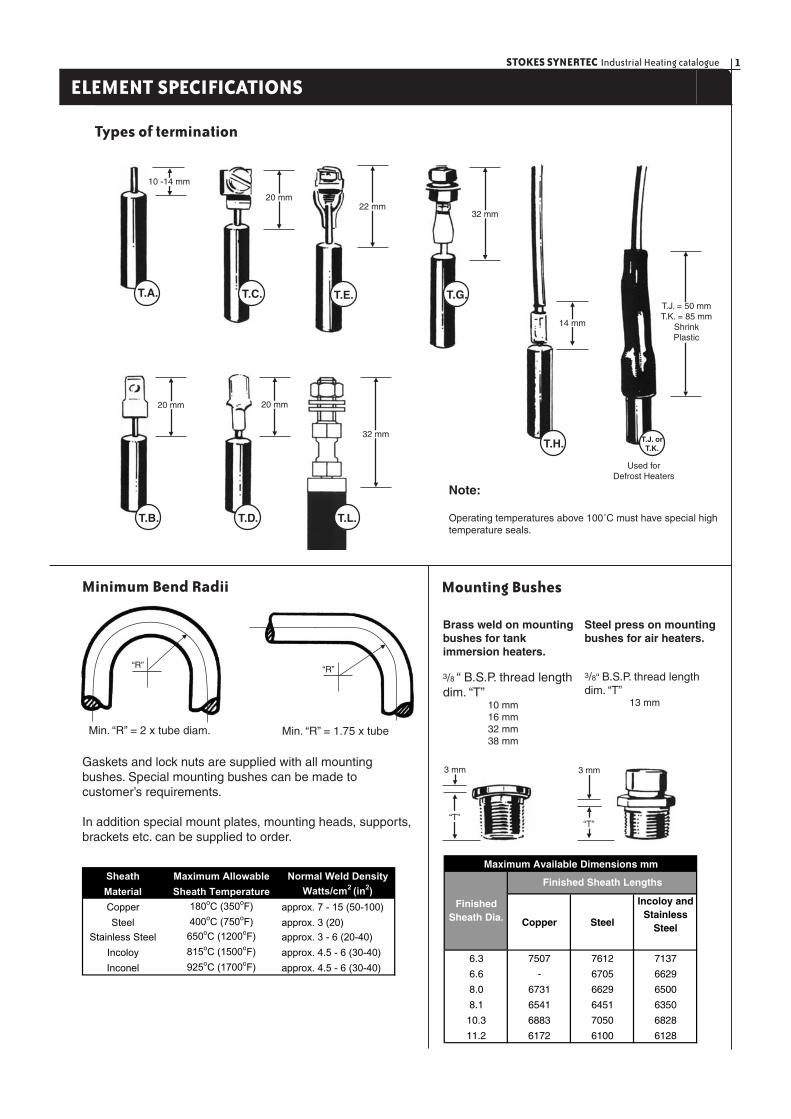
Min. “R” = 2 x tube diam. Min. “R” = 1.75 x tube
Gaskets and lock nuts are supplied with all mounting bushes. Special mounting bushes can be made to customer’s requirements.
In addition special mount plates, mounting heads, supports, brackets etc. can be supplied to order.
T.A. T.C. T.E. T.G.
T.B. T.D. T.L.
T.H. T.J. orT.K.
Used for Defrost Heaters
Brass weld on mounting bushes for tankimmersion heaters.
Steel press on mounting bushes for air heaters.
3/8 “ B.S.P. thread length dim. “T” 10 mm 16 mm 32 mm 38 mm
3/8“ B.S.P. thread length dim. “T” 13 mm
“T”
3 mm
“T”
3 mm
Maximum Available Dimensions mm
Copper Steel
Incoloy and Stainless
Steel
6.3 7507 7612 7137
6.6 - 6705 6629
8.0 6731 6629 6500
8.1 6541 6451 6350
10.3 6883 7050 6828
11.2 6172 6100 6128
Finished Sheath Lengths
Finished Sheath Dia.
Note:
Operating temperatures above 100˚C must have special high temperature seals.
Sheath Maximum Allowable Normal Weld Density
Material Sheath Temperature Watts/cm2 (in2)
Copper 180oC (350oF) approx. 7 - 15 (50-100)
Steel 400oC (750oF) approx. 3 (20)
Stainless Steel 650oC (1200oF) approx. 3 - 6 (20-40)
Incoloy 815oC (1500oF) approx. 4.5 - 6 (30-40)
Inconel 925oC (1700oF) approx. 4.5 - 6 (30-40)
ELEMENT SPECIFICATIONS
Minimum Bend Radii Mounting Bushes
Types of termination
STOKES SYNERTEC Industrial Heating catalogue2
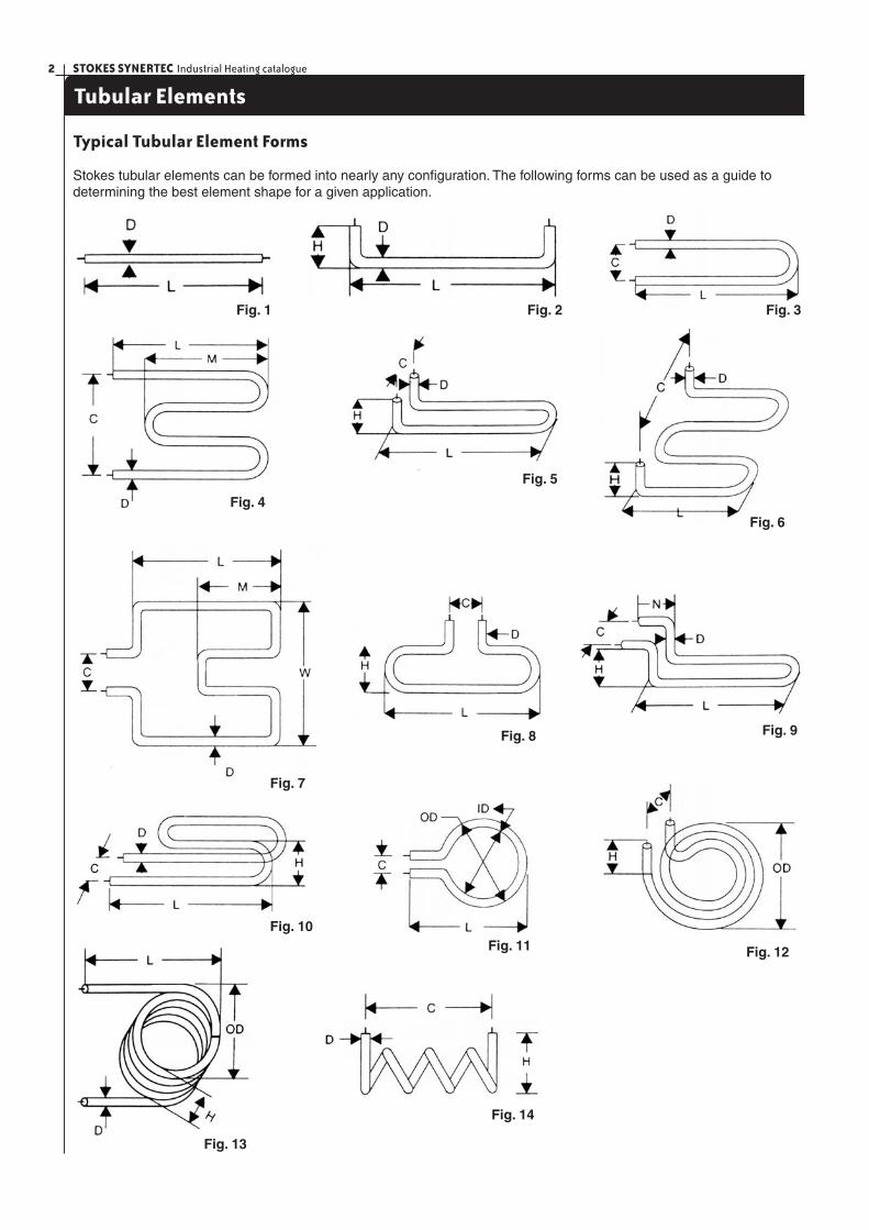
Tubular Elements
Typical Tubular Element Forms
Stokes tubular elements can be formed into nearly any confi guration. The following forms can be used as a guide to determining the best element shape for a given application.
Fig. 1 Fig. 2 Fig. 3
Fig. 4
Fig. 5
Fig. 6
Fig. 7
Fig. 8 Fig. 9
Fig. 10Fig. 11 Fig. 12
Fig. 13
Fig. 14

3STOKES SYNERTEC Industrial Heating catalogue
Straight Length Tubular Elements with Terminals
Oil, Water and Air Immersion
Stokes Synertec’s Straight Length Tubular elements are available in two sheath materials. Incoloy sheath for oil immersion, copper sheath for water and incoloy for air heating. They can be formed to suit the heating pattern that you require.
Note: Special wattages, lengths and diameters can be made to suit the customer’s requirements.
Water Immersion
Cat. No. Cat. No. Watts Volts Dim HeatedCopper Sheath Incoloy Sheath "A" Length(120 kW/sq.m) (120 kW/sq.m) "B"
2231-15 2221-15 600 240 285 2002232-15 2222-15 800 240 385 3052233-15 2223-15 1200 240 485 4052234-15 2224-15 1500 240 585 5052235-15 2225-15 1800 240 685 6052236-15 2226-15 2000 240 755 6752237-15 2227-15 2400 240 890 8102238-15 2228-15 3000 240 1090 9602239-15 2229-15 3600 240 1290 11502240-15 2230-15 4800 240 1690 1550
Copper Sheath/Incoloy Sheath (120 kW/sq.m)Cat. No. Watts Volts Dim Heated
"A" Length"B"
2380-15 600 240 436 3052381-15 800 240 586 4582382-15 1200 240 736 6052383-15 1500 240 883 7572384-15 1800 240 1036 9002385-15 2000 240 1139 10102386-15 2400 240 1339 12102387-15 3000 240 1642 15152388-15 3600 240 1944 18702389-15 4800 240 2549 2425
Incoloy Sheath (77 kW/sq.m)
Air Heaters Air/Oil Heaters
Watts Volts Dim Heated"A" Length
INC 800 S/Steel "B"2201-15 3951-15 500 240 495 3452202-15 3952-15 750 240 715 5602203-15 3953-15 1000 240 915 7602204-15 3954-15 1250 240 1135 9852205-15 3955-15 1500 240 1335 11852206-15 3956-15 1800 240 1595 14452207-15 3957-15 2000 240 1775 16202208-15 3958-15 2500 240 2195 20502209-15 3959-15 3000 240 2615 24702210-15 3960-15 4000 240 3742 3576
Incoloy Sheath (46.5 kW/sq.m)Cat. No. Watts Volts Dim Heated
"A" LengthINC 800 S/STEEL "B"2211-15 3971-15 500 240 715 5602212-15 3972-15 800 240 1035 8802213-15 3973-15 1000 240 1335 11852214-15 3974-15 1250 240 1675 15302215-15 3975-15 1500 240 1975 18302216-15 3976-15 1800 240 2355 22152217-15 3977-15 2000 240 2625 24702218-15 3978-15 2500 240 3255 3115
Incoloy Sheath (31 kW/sq.m)Cat. No.
8mmHeated length “B”
STOKES SYNERTEC Industrial Heating catalogue4
Heated length “B”
Dim “A”8 mm 3/8 BSP
Bushes40 mm‘Max’
Heated length “B”
Dim “A”8 mm 3/8 BSP
Bushes40 mm‘Max’
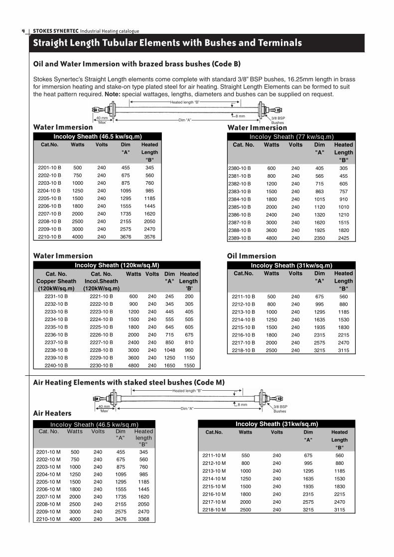
Straight Length Tubular Elements with Bushes and Terminals
Oil and Water Immersion with brazed brass bushes (Code B)
Stokes Synertec’s Straight Length elements come complete with standard 3/8” BSP bushes, 16.25mm length in brass for immersion heating and stake-on type plated steel for air heating. Straight Length Elements can be formed to suit the heat pattern required. Note: special wattages, lengths, diameters and bushes can be supplied on request.
Water Immersion
Air Heaters
Water Immersion
Cat. No. Cat. No. Watts Volts Dim HeatedCopper Sheath Incol.Sheath "A" Length (120kW/sq.m) (120kW/sq.m) 'B'
2231-10 B 2221-10 B 600 240 245 200
2232-10 B 2222-10 B 900 240 345 305
2233-10 B 2223-10 B 1200 240 445 405
2234-10 B 2224-10 B 1500 240 555 505
2235-10 B 2225-10 B 1800 240 645 605
2236-10 B 2226-10 B 2000 240 715 675
2237-10 B 2227-10 B 2400 240 850 810
2238-10 B 2228-10 B 3000 240 1048 960
2239-10 B 2229-10 B 3600 240 1250 1150
2240-10 B 2230-10 B 4800 240 1650 1550
Incoloy Sheath (120kw/sq.M)
Cat. No. Watts Volts Dim Heated"A" Length
"B"2380-10 B 600 240 405 305
2381-10 B 800 240 565 455
2382-10 B 1200 240 715 605
2383-10 B 1500 240 863 757
2384-10 B 1800 240 1015 910
2385-10 B 2000 240 1120 1010
2386-10 B 2400 240 1320 1210
2387-10 B 3000 240 1620 1515
2388-10 B 3600 240 1925 1820
2389-10 B 4800 240 2350 2425
Incoloy Sheath (77 kw/sq.m)
Air Heating Elements with staked steel bushes (Code M)
Cat.No. Watts Volts Dim Heated
"A" Length
"B"
2211-10 M 550 240 675 560
2212-10 M 800 240 995 880
2213-10 M 1000 240 1295 1185
2214-10 M 1250 240 1635 1530
2215-10 M 1500 240 1935 1830
2216-10 M 1800 240 2315 2215
2217-10 M 2000 240 2575 2470
2218-10 M 2500 240 3215 3115
Incoloy Sheath (31kw/sq.m)
Cat.No. Watts Volts Dim Heated
"A" Length
"B"
2201-10 B 500 240 455 345
2202-10 B 750 240 675 560
2203-10 B 1000 240 875 760
2204-10 B 1250 240 1095 985
2205-10 B 1500 240 1295 1185
2206-10 B 1800 240 1555 1445
2207-10 B 2000 240 1735 1620
2208-10 B 2500 240 2155 2050
2209-10 B 3000 240 2575 2470
2210-10 B 4000 240 3676 3576
Incoloy Sheath (46.5 kw/sq.m)
Cat.No. Watts Volts Dim Heated"A" Length
"B"2211-10 B 500 240 675 560
2212-10 B 800 240 995 880
2213-10 B 1000 240 1295 1185
2214-10 B 1250 240 1635 1530
2215-10 B 1500 240 1935 1830
2216-10 B 1800 240 2315 2215
2217-10 B 2000 240 2575 2470
2218-10 B 2500 240 3215 3115
Incoloy Sheath (31kw/sq.m)
Water Immersion Oil Immersion
Cat. No. Watts Volts Dim Heated"A" length
"B"2201-10 M 500 240 455 345
2202-10 M 750 240 675 560
2203-10 M 1000 240 875 760
2204-10 M 1250 240 1095 985
2205-10 M 1500 240 1295 1185
2206-10 M 1800 240 1555 1445
2207-10 M 2000 240 1735 1620
2208-10 M 2500 240 2155 2050
2209-10 M 3000 240 2575 2470
2210-10 M 4000 240 3476 3368
Incoloy Sheath (46.5 kw/sq.m)
5STOKES SYNERTEC Industrial Heating catalogue
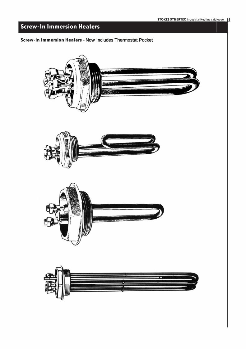
Screw-In Immersion Heaters
Screw-in Immersion Heaters - Now Includes Thermostat Pocket.
STOKES SYNERTEC Industrial Heating catalogue6
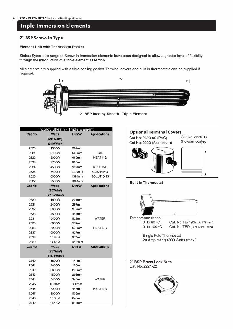
Triple Immersion Elements
2” BSP Screw-In Type
Element Unit with Thermostat Pocket
Stokes Synertec’s range of Screw-In Immersion elements have been designed to allow a greater level of fl exibilty through the introduction of a triple element assembly.
All elements are supplied with a fi bre sealing gasket. Terminal covers and built in thermostats can be supplied if required.
Optional Terminal Covers
Built-in Thermostat
Temperature range: 0 to 80 oC Cat. No.TE/7 (Dim A: 178 mm)
0 to 100 oC Cat. No.TED (Dim A: 280 mm)
Single Pole Thermostat 20 Amp rating 4800 Watts (max.)
2” BSP Brass Lock NutsCat. No. 2221-22
Cat No. 2620-14 (Powder coated)
Cat.No. Watts Dim'A' Applications
(20 W/in²)
(31kW/m²)
2620 1500W 364mm
2621 2400W 585mm OIL
2622 3000W 680mm HEATING
2623 3750W 855mm
2624 4500W 997mm ALKALINE
2625 5400W 1190mm CLEANING
2626 6000W 1320mm SOLUTIONS
2627 7500W 1640mm
Cat.No. Watts Dim'A' Applications
(50W/in²)
(77.5kW/m²)
2630 1800W 221mm
2631 2400W 297mm
2632 3600W 372mm
2633 4500W 447mm
2634 5400W 522mm WATER
2635 6000W 574mm
2636 7200W 675mm HEATING
2637 9000W 827mm
2638 10.8KW 974mm
2639 14.4KW 1282mm
Cat.No. Watts Dim'A' Applications
(75W/in²)
(116 kW/m²)
2640 1800W 144mm
2641 2400W 195mm
2642 3600W 246mm
2643 4500W 296mm
2644 5400W 346mm WATER
2645 6000W 380mm
2646 7200W 448mm HEATING
2647 9000W 553mm
2648 10.8KW 643mm
2649 14.4KW 845mm
Incoloy Sheath - Triple Element
Cat No: 2620-09 (PVC)Cat No: 2220 (Aluminium)
A
2” BSP Incoloy Sheath - Triple Element
“A”
7STOKES SYNERTEC Industrial Heating catalogue
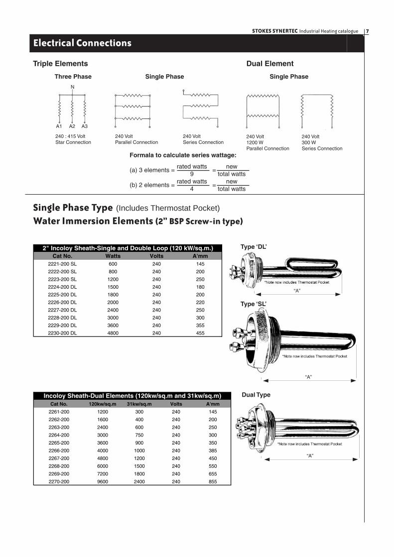
Electrical Connections
Triple Elements
Three Phase Single Phase Single Phase
Dual Element
Formala to calculate series wattage:
(a) 3 elements = =
(b) 2 elements = =
rated watts9
newtotal watts
rated watts4
newtotal watts
Single Phase Type (Includes Thermostat Pocket)
Water Immersion Elements (2” BSP Screw-in type)
Cat No. Watts Volts A'mm2221-200 SL 600 240 145
2222-200 SL 800 240 200
2223-200 SL 1200 240 250
2224-200 DL 1500 240 180
2225-200 DL 1800 240 200
2226-200 DL 2000 240 220
2227-200 DL 2400 240 250
2228-200 DL 3000 240 300
2229-200 DL 3600 240 355
2230-200 DL 4800 240 455
2" Incoloy Sheath-Single and Double Loop (120 kW/sq.m.)
Cat No. 120kw/sq.m 31kw/sq.m Volts A'mm
2261-200 1200 300 240 145
2262-200 1600 400 240 200
2263-200 2400 600 240 250
2264-200 3000 750 240 300
2265-200 3600 900 240 350
2266-200 4000 1000 240 385
2267-200 4800 1200 240 450
2268-200 6000 1500 240 550
2269-200 7200 1800 240 655
2270-200 9600 2400 240 855
Incoloy Sheath-Dual Elements (120kw/sq.m and 31kw/sq.m)
Type ‘DL’
Dual Type
N
A1 A2 A3
240 : 415 VoltStar Connection
240 VoltParallel Connection
240 VoltSeries Connection
240 Volt1200 WParallel Connection
240 Volt300 WSeries Connection
“A”
“A”
“A”
Type ‘SL’
STOKES SYNERTEC Industrial Heating catalogue8
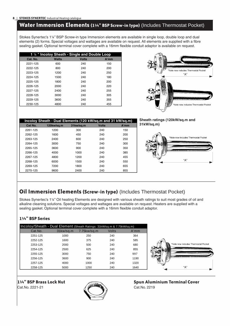
Water Immersion Elements (1¼” BSP Screw-in type) (Includes Thermostat Pocket)
Stokes Synertec’s 1¼” BSP Screw-in type Immersion elements are available in single loop, double loop and dual elements (2) forms. Special voltages and wattages are available on request. All elements are supplied with a fi bre sealing gasket. Optional terminal cover complete with a 16mm fl exible conduit adaptor is available on request.
Cat. No. Watts Volts A'mm
2221-125 600 240 150
2222-125 800 240 200
2223-125 1200 240 250
2224-125 1500 240 180
2225-125 1800 240 200
2226-125 2000 240 220
2227-125 2400 240 255
2228-125 3000 240 305
2229-125 3600 240 355
2230-125 4800 240 455
1 ¼ " Incoloy Sheath - Single and Double Loop
Cat No. 120kw/sq.m 31kw/sq.m Volts A'mm
2261-125 1200 300 240 150
2262-125 1600 450 240 200
2263-125 2400 600 240 250
2264-125 3000 750 240 300
2265-125 3600 900 240 350
2266-125 4000 1000 240 385
2267-125 4800 1200 240 455
2268-125 6000 1500 240 550
2269-125 7200 1800 240 655
2270-125 9600 2400 240 855
Incoloy Sheath - Dual Elements (120 kW/sq.m and 31 kW/sq.m) Sheath ratings (120kW/sq.m and 31kW/sq.m)
Oil Immersion Elements (Screw-in type) (Includes Thermostat Pocket)
Stokes Synertec’s 1¼” Oil heating Elements are designed with various sheath ratings to suit most grades of oil and alkaline cleaning solutions. Special voltages and wattages are available on request. Heaters are supplied with a sealing gasket. Optional terminal cover complete with a 16mm fl exible conduit adaptor.
1¼” BSP Series
Cat.No. 31kw/sq.m 7.75kw/sq.m Volts A'mm2251-125 1000 250 240 364
2252-125 1600 375 240 585
2253-125 2000 500 240 680
2254-125 2500 625 240 855
2255-125 3000 750 240 997
2256-125 3600 900 240 1190
2257-125 4000 1000 240 1320
2258-125 5000 1250 240 1640
Incoloy/Sheath - Dual Element (Sheath Ratings: 31kW/sq.m & 7.75kW/sq.m)
1¼” BSP Brass Lock NutCat.No. 2221-21
“A”
“A”
“A”
Spun Aluminium Terminal CoverCat.No. 2219
9STOKES SYNERTEC Industrial Heating catalogue
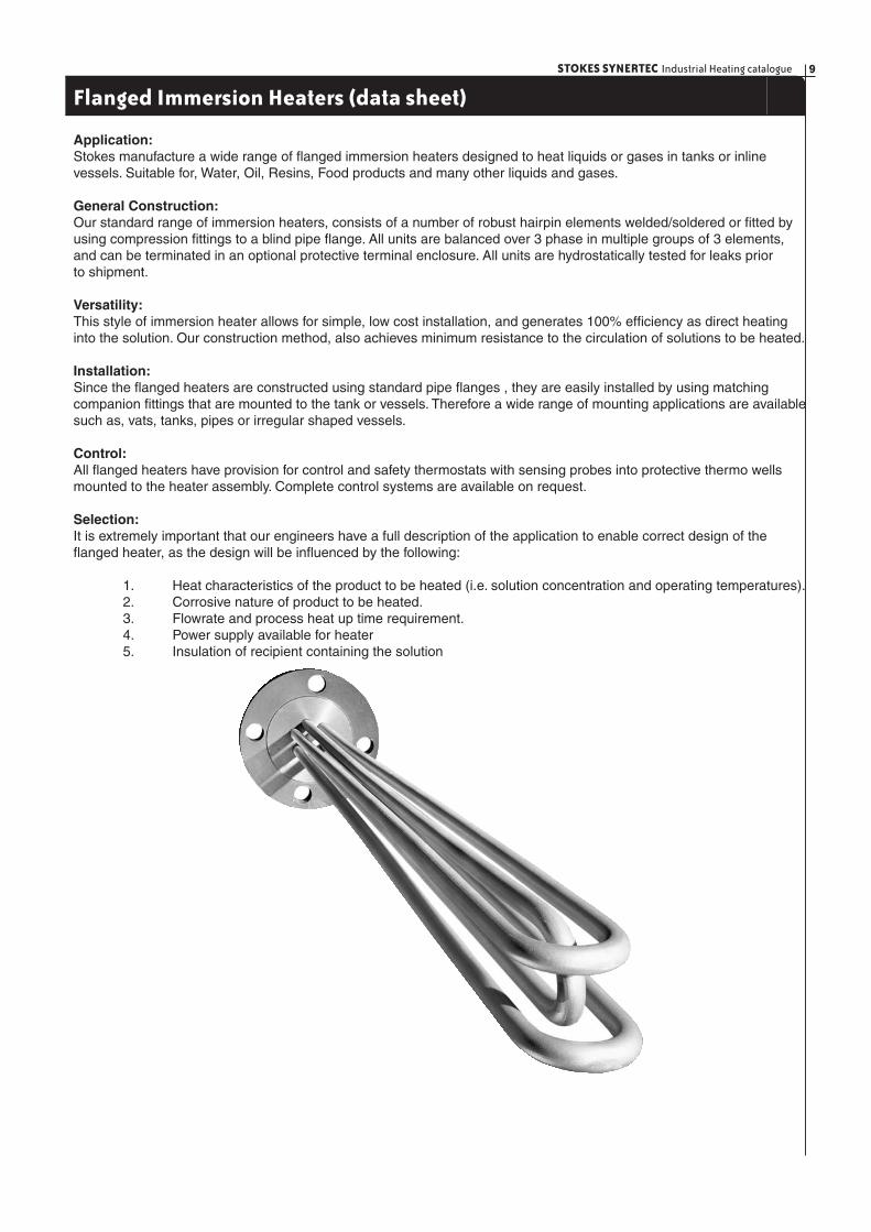
Flanged Immersion Heaters (data sheet)
Application:Stokes manufacture a wide range of fl anged immersion heaters designed to heat liquids or gases in tanks or inline vessels. Suitable for, Water, Oil, Resins, Food products and many other liquids and gases.
General Construction:Our standard range of immersion heaters, consists of a number of robust hairpin elements welded/soldered or fi tted by using compression fi ttings to a blind pipe fl ange. All units are balanced over 3 phase in multiple groups of 3 elements, and can be terminated in an optional protective terminal enclosure. All units are hydrostatically tested for leaks prior to shipment.
Versatility:This style of immersion heater allows for simple, low cost installation, and generates 100% effi ciency as direct heating into the solution. Our construction method, also achieves minimum resistance to the circulation of solutions to be heated.
Installation:Since the fl anged heaters are constructed using standard pipe fl anges , they are easily installed by using matching companion fi ttings that are mounted to the tank or vessels. Therefore a wide range of mounting applications are available such as, vats, tanks, pipes or irregular shaped vessels.
Control:All fl anged heaters have provision for control and safety thermostats with sensing probes into protective thermo wells mounted to the heater assembly. Complete control systems are available on request.
Selection:It is extremely important that our engineers have a full description of the application to enable correct design of the fl anged heater, as the design will be infl uenced by the following:
1. Heat characteristics of the product to be heated (i.e. solution concentration and operating temperatures). 2. Corrosive nature of product to be heated. 3. Flowrate and process heat up time requirement. 4. Power supply available for heater 5. Insulation of recipient containing the solution
STOKES SYNERTEC Industrial Heating catalogue10
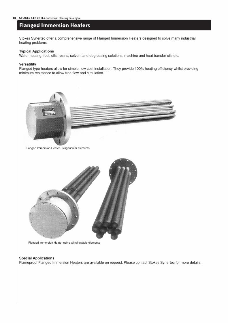
Flanged Immersion Heaters
Stokes Synertec offer a comprehensive range of Flanged Immersion Heaters designed to solve many industrial heating problems.
Typical ApplicationsWater heating, fuel, oils, resins, solvent and degreasing solutions, machine and heat transfer oils etc.
VersatilityFlanged type heaters allow for simple, low cost installation. They provide 100% heating effi ciency whilst providing minimum resistance to allow free fl ow and circulation.
Flanged Immersion Heater using withdrawable elements
Flanged Immersion Heater using tubular elements
Special ApplicationsFlameproof Flanged Immersion Heaters are available on request. Please contact Stokes Synertec for more details.
11STOKES SYNERTEC Industrial Heating catalogue
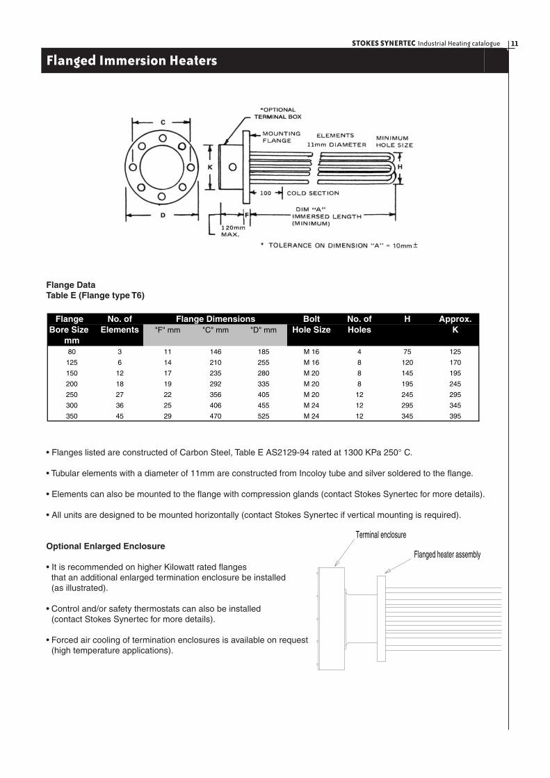
Flanged Immersion Heaters
• Flanges listed are constructed of Carbon Steel, Table E AS2129-94 rated at 1300 KPa 250° C.
• Tubular elements with a diameter of 11mm are constructed from Incoloy tube and silver soldered to the fl ange.
• Elements can also be mounted to the fl ange with compression glands (contact Stokes Synertec for more details).
• All units are designed to be mounted horizontally (contact Stokes Synertec if vertical mounting is required).
Optional Enlarged Enclosure
• It is recommended on higher Kilowatt rated fl anges that an additional enlarged termination enclosure be installed (as illustrated).
• Control and/or safety thermostats can also be installed (contact Stokes Synertec for more details).
• Forced air cooling of termination enclosures is available on request (high temperature applications).
Flange DataTable E (Flange type T6)
Flange No. of Bolt No. of H Approx.Bore Size Elements "F" mm "C" mm "D" mm Hole Size Holes K
mm80 3 11 146 185 M 16 4 75 125
125 6 14 210 255 M 16 8 120 170
150 12 17 235 280 M 20 8 145 195
200 18 19 292 335 M 20 8 195 245
250 27 22 356 405 M 20 12 245 295
300 36 25 406 455 M 24 12 295 345
350 45 29 470 525 M 24 12 345 395
Flange Dimensions
Flanged heater assembly
Terminal enclosure

STOKES SYNERTEC Industrial Heating catalogue12
Flanged Immersion Heaters
Ordering Data: quote catalogue number, watts, volts and application. Please indicate any special features that are required (i.e. 2712-36 = 54kW 415/240V)
Incoloy 800 Sheath Average watts density over sheath area - 31 kW/m2 (20w/in2)
415/240 Volt 415 Volt 80mm 125mm 150mm 200mm 250mm 300mm 350mmStar Delta
Connected ConnectedCat.No. Cat.No -3 -6 -12 -18 -27 -36 -45 Dim"A"
2711 2731 3KW 6KW 12KW 18KW 27KW 36KW 45KW 554mm
2712 2732 4.5KW 9KW 18KW 27KW 40.5KW 54KW 67.5KW 784mm
2713 2733 6KW 12KW 24KW 36KW 54KW 72KW 90KW 1014mm
2714 2734 7.5KW 15KW 30KW 45KW 67.5KW 90KW 112.4KW 1243mm
2715 2735 9KW 18KW 36KW 54KW 81KW 108KW 135KW 1473mm
2716 2736 10.5KW 21KW 42KW 63KW 94.5KW 126KW 157.5KW 1703mm
2717 2737 12KW 24KW 48KW 72KW 108KW 144KW 180KW 1932mm
2718 2738 15KW 30KW 60KW 90KW 135KW 180KW 225KW 2392mm
Voltage Flange Bore Size
Incoloy 800 Sheath Average watts density over sheath area - 77.5 kW/m2 (50w/in2)
415/240 Volt 415 VoltStar Delta 80mm 125mm 150mm 200mm 250mm 300mm 350mnm
Connected ConnectedCat.No. Cat No. -3 -6 -12 -18 -27 -36 -45 Dim"A"
2720 2740 6KW 12KW 24KW 36KW 54KW 72KW 90KW 462mm
2721 2741 7.5KW 15KW 30KW 45KW 67.5KW 90KW 112.5KW 554mm
2722 2742 9KW 18KW 36KW 54KW 81KW 108KW 135KW 646mm
2723 2743 10.5KW 21KW 42KW 63KW 94.5KW 126KW 157.5KW 738mm
2724 2744 12KW 24KW 48KW 72KW 108KW 144KW 180KW 830mm
2725 2745 13.5KW 27KW 54KW 81KW 121.5KW 162KW 202.5KW 922mm
2726 2746 15KW 30KW 60KW 90KW 135KW 180KW 225KW 1014mm
2727 2747 16.5KW 33KW 66KW 99KW 148.5KW 198KW 247.5KW 1106mm
2728 2748 18KW 36KW 72KW 108KW 162KW 216KW 270KW 1197mm
2729 2749 19.5KW 39KW 78KW 117KW 175.5KW 234KW 292.5KW 1289mm
2730 2750 21KW 42KW 84KW 126KW 189KW 252KW 315KW 1357mm
2751 24KW 48KW 96KW 144KW 216KW 288KW 360KW 1565mm
2752 27KW 54KW 108KW 162KW 243KW 324KW 405KW 1749mm
2753 30KW 60KW 120KW 180KW 270KW 360KW 450KW 1932mm
Voltage Flange Bore Size
Special Ratings:Variations in wattage and voltage can be supplied (within practical limits). Contact Stokes Synertec for more details.
Corrosion Policy:STOKES can not warrant any electrical immersion heater against failure by sheath corrosion if such failure is the result of operating conditions beyond the control of the heater design. It is the responsibility of the purchaser to make the fi nal choice of sheath material based on their knowledge of chemical composition of the corrosive solution to be used.
*Note: Terminal Covers are an optional extra
13STOKES SYNERTEC Industrial Heating catalogue
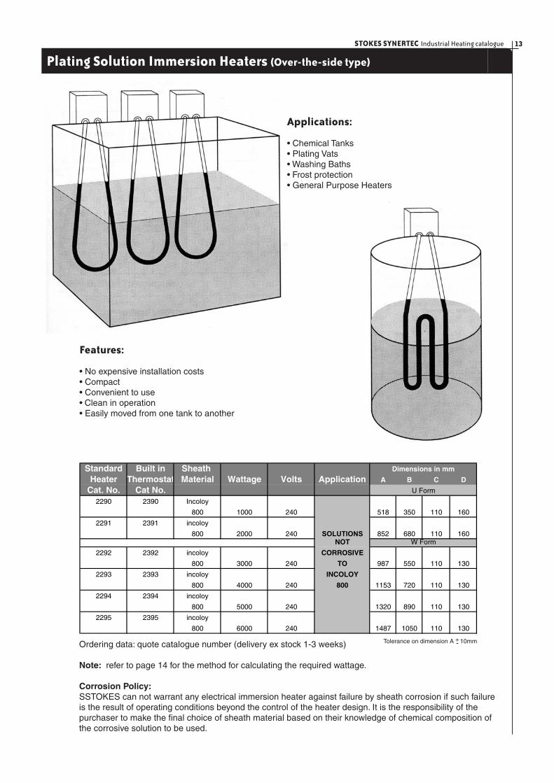
Plating Solution Immersion Heaters (Over-the-side type)
Ordering data: quote catalogue number (delivery ex stock 1-3 weeks)
Note: refer to page 14 for the method for calculating the required wattage.
Corrosion Policy:SSTOKES can not warrant any electrical immersion heater against failure by sheath corrosion if such failure is the result of operating conditions beyond the control of the heater design. It is the responsibility of the purchaser to make the fi nal choice of sheath material based on their knowledge of chemical composition of the corrosive solution to be used.
Tolerance on dimension A + 10mm-
Applications:
• Chemical Tanks• Plating Vats• Washing Baths• Frost protection• General Purpose Heaters
Features:
• No expensive installation costs• Compact• Convenient to use• Clean in operation• Easily moved from one tank to another
Standard Built in Sheath Heater Thermostat Material Wattage Volts Application A B C D
Cat. No. Cat No.2290 2390 Incoloy
800 1000 240 518 350 110 160
2291 2391 incoloy
800 2000 240 SOLUTIONS 852 680 110 160NOT
2292 2392 incoloy CORROSIVE
800 3000 240 TO 987 550 110 130
2293 2393 incoloy INCOLOY
800 4000 240 800 1153 720 110 130
2294 2394 incoloy
800 5000 240 1320 890 110 130
2295 2395 incoloy
800 6000 240 1487 1050 110 130
W Form
Dimensions in mm
U Form

STOKES SYNERTEC Industrial Heating catalogue14
Metal Sheathed
Stokes Synertec’s Over-the-side immersionheaters provide an easy means of heating solutions in tanks.
• Installation costs are signifi cantly reduced due to heaters being hung over the side of tanks. • Standard heaters are available ex- stock in the range listed. • Special shape modifi cations can be manufactured to suit shallow tanks and specifi c user requirements. • Terminations are enclosed in a moisture-proof P.V.C. box.
Additional features:
• Built in Control Thermostat 20°C to 120°C scale range (15 amp rating). • Special voltage or wattage. • Special bending confi gurations. • Different sheath materials (contact Stokes Synertec).
Orders & enquiries:
• When ordering please state the solutions to be heated, working temperature and minimum liquid level. • State dimensions and shape of heater preffered.
Plating Solution Immersion Heaters (Over- the-side type)
Fahr. 100o 110o 120o 130o 140o 150o 160o 170o 180o 190o 200o
Cent. 38o 43o 49o 55o 60o 65o 71o 77o 82o 88o 93o
Gallons Litres kW kW kW kW kW kW kW kW kW kW kW
50 227 0.5 0.75 1 1.5 1.5 2 2 2 3 3 3
75 341 1 1 1.5 1.5 2 2 3 3 3 4 4
100 455 1.5 1.5 2 3 3 3 4 4 4 5 5
125 568 1.5 2 3 3 4 4 4 5 5 5 6
150 682 2 2 3 3 4 4 5 5 6 6 7
175 796 3 3 4 4 5 5 5 6 6 7 7
200 910 3 3 4 4 5 5 6 6 7 8 9
250 1137 3 4 4 5 5 7 7 8 9 10 11
300 1365 4 5 6 6 8 9 10 10 11 11 12
350 1592 5 6 7 8 9 10 11 12 13 14 15
400 1820 6 7 8 9 10 11 12 13 14 16 17
450 2047 6 7 9 10 11 12 14 15 16 18 18
500 2275 7 8 9 11 12 13 15 17 18 20 21
Tank Capacity
Operating Temperature
Quick Calculation Chart for heat requirements
Note: • These wattages are based on an 8 hour heat-up time with an ambient temperature of 21oC (70oF). • Kilowatt ratings are calculated on tanks having a 50mm insulation and are enclosed. • To reduce heat-up time increase the wattage proportionately.
“U” Form Series
“W” Form Series
“Cold Zone”
“Cold Zone”
+-

STOKES SYNERTEC Industrial Heating catalogue16
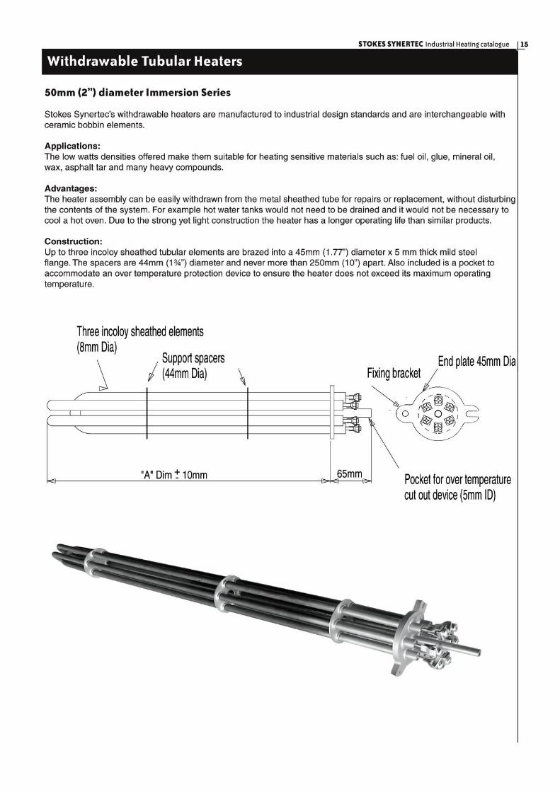
Withdrawable Tubular Heaters
Refer to technical section for suggested maximum watts density ratings.
Refer to technical section for suggested maximum watts density ratings page 45.
Heater Watts Density6.2 Kw/m2 12.4 Kw/m2 18.6 Kw/m2 31.0 Kw/m2 Heater Length
240V 415V (4 W/in2) (8 W/in2) (12 W/in2) (20 W/in2) Dim "A"
2665 600W 300mm
2666 750W 300mm
2667 600W 450mm
2668 900W 450mm
2669 1500W 450mm
2670 2770 750W 550mm
2671 2771 1000W 550mm
2672 2772 1500W 550mm
2673 2773 2500W 550mm
2674 2774 1000W 1000mm
2675 2775 2000W 1000mm
2676 2776 3000W 1000mm
2677 2777 5000W 1000mm
2678 2778 1500W 1450mm
2679 2779 3000W 1450mm
2680 2780 4500W 1450mm
2681 2781 7500W 1450mm
2682 2782 2000W 1900mm
2683 2783 4000W 1900mm
2684 2784 6000W 1900mm
2685 2785 10000W 1900mm
2686 2786 2500W 2350mm
2687 2787 5000W 2350mm
2688 2788 7500W 2350mm
2689 2789 12500W 2350mm
2690 2790 3000W 2750mm
2691 2791 6000W 2750mm
2692 2792 9000W 2750mm
2693 2793 15000W 2750mm
2694 2794 3500W 3200mm
2695 2795 7000W 3200mm
2696 2796 10500W 3200mm
2697 2797 17500W 3200mm
Assembly CatNumber
17STOKES SYNERTEC Industrial Heating catalogue
Withdrawable Tubular Heaters
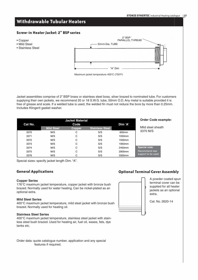
Maximum jacket temperature 400oC (750oF)
Jacket MaterialCat No. Dim 'A'
Mild Steel Copper Stainless Steel3370 M/S C S/S 600mm
3371 M/S C S/S 1050mm
3372 M/S C S/S 1500mm
3373 M/S C S/S 1950mm
3374 M/S C S/S 2450mm
3375 M/S C S/S 2900mm
3376 M/S C S/S 3300mm
CodeOrder Code example:
Mild steel sheath3370 M/S
Special note:
Recommend rear support to be used
Special sizes: specify jacket length Dim. “A”.
General Applications
Copper Series176°C maximum jacket temperature, copper jacket with bronze bush brazed. Normally used for water heating. Can be nickel-plated as an optional extra.
Mild Steel Series400°C maximum jacket temperature, mild steel jacket with bronze bush brazed. Normally used for heating oil.
Stainless Steel Series400°C maximum jacket temperature, stainless steel jacket with stain-less steel bush brazed. Used for heating air, fuel oil, waxes, fats, dye tanks etc.
Order data: quote catalogue number, application and any special features if required.
Optional Terminal Cover Assembly
A powder coated spun terminal cover can be supplied for all heater jackets as an optional extra.
Cat. No. 2620-14
Screw-in Heater Jacket: 2” BSP series
• Copper• Mild Steel• Stainless Steel
Jacket assemblies comprise of 2” BSP brass or stainless steel boss, silver brazed to nominated tube. For customers supplying their own jackets, we recommend 20 or 18 S.W.G. tube, 50mm O.D. Any metal is suitable provided it is free of grease and scale. If a welded tube is used, the welded fi n must not reduce the bore by more than 0.25mm. Includes Klingerit gasket washer.
STOKES SYNERTEC Industrial Heating catalogue18
Withdrawable Tubular Heaters
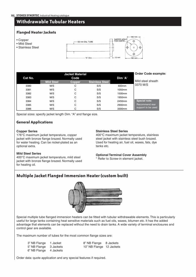
Flanged Heater Jackets
• Copper• Mild Steel• Stainless Steel
Order Code example:
Mild steel sheath3370 M/S
Special sizes: specify jacket length Dim. “A” and fl ange size.
General Applications
Copper Series176°C maximum jacket temperature, copper jacket with bronze fl ange brazed. Normally used for water heating. Can be nickel-plated as an optional extra.
Mild Steel Series400°C maximum jacket temperature, mild steel jacket with bronze fl ange brazed. Normally used for heating oil.
Stainless Steel Series400°C maximum jacket temperature, stainless steel jacket with stainless steel bush brazed. Used for heating air, fuel oil, waxes, fats, dye tanks etc.
Optional Terminal Cover Assembly* Refer to Screw-in element jacket.
Multiple Jacket Flanged Immersion Heater (custom built)
Special multiple tube fl anged immersion heaters can be fi tted with tubular withdrawable elements. This is particularly useful for large tanks containing heat sensitive materials such as fuel oils, waxes, bitumen etc. It has the added advantage that elements can be replaced without the need to drain tanks. A wide variety of terminal enclosures and control gear are available.
The maximum number of tubes for the most common fl ange sizes are:
3” NB Flange 1 Jacket 8” NB Flange 8 Jackets 5” NB Flange 3 Jackets 10” NB Flange 12 Jackets 6” NB Flange 4 Jackets
Order data: quote application and any special features if required.
Jacket MaterialCat No. Dim 'A'
Mild Steel Copper Stainless Steel3380 M/S C S/S 600mm
3381 M/S C S/S 1050mm
3382 M/S C S/S 1500mm
3383 M/S C S/S 1950mm
3384 M/S C S/S 2450mm
3385 M/S C S/S 2900mm
3386 M/S C S/S 3300mm
Code
Special note:
Recommend rear support to be used

19STOKES SYNERTEC Industrial Heating catalogue
Air Heating
Unfi nned - Incoloy Sheath ApplicationStokes Synertec Incoloy Sheathed Unfi nned elements are designed for forced air heating in ducts, comfort heaters, recirculating ovens and other industrial processing equipment and processes requiring heated air. They can also be used for radiant heat and load resistors.
InstallationFor duct mounting, bushes are designed to provide rigid leak proof support. Heaters should be evenly spaced with alternate rows staggered. For bush mounting 18 mmclearance holes are required. For temperatures exceeding 60°C, electrical connections should be made with correct heat resisting cable.
FeaturesThe Stokes Synertec Tubular element is made of a corrosion resistant alloy and has a diameter of 8.15 mm (.320”). Each element is fi tted with mounting bushes 3/8 ” BSP x 1/2 ” long,galvanised washers, locknuts and M4screwed terminals.
Note: operating temperatures above 100°C must have special high temperature seals.
46.5 kW Per Sq. Metre Series (Min. air fl ow 1.83 m/sec. Max. sheath temperature 650°C) Delivery ex stock: 1 to 3 weeks.
31 kW Per Sq. Metre Series (Min. air fl ow 1.22 m/sec. Max. sheath temperature 650°C) Delivery ex stock: 1 to 3 weeks.
Note: 200 Volt series for export only. Note: 200 Volt series for export only.
Note: 200 Volt series for export only.Note: 200 Volt series for export only.
For special wattages and lengths consult your Stokes Synertec representative.
"U" FormRating Dim "A" max. kg
240 Volt 200 Volt Watts mm2201-U 2861-U 500 215 0.15
2202-U 2862-U 750 325 0.23
2203-U 2863-U 1000 425 0.27
2204-U 2864-U 1250 535 0.36
2205-U 2865-U 1500 635 0.4
2206-U 2866-U 1800 765 0.5
2207-U 2867-U 2000 855 0.7
2208-U 2868-U 2500 1065 0.8
2209-U 2869-U 3000 1275 0.9
2210-U 2870-U 4000 1836 1
Cat No."W" Form
Rating Dim. "A" max. kg240 Volt 200 Volt Watts mm2201-W 2861-W 500 125 0.15
2202-W 2862-W 750 180 0.23
2203-W 2863-W 1000 230 0.27
2204-W 2864-W 1250 285 0.36
2205-W 2865-W 1500 335 0.4
2206-W 2866-W 1800 400 0.5
2207-W 2867-W 2000 445 0.7
2208-W 2868-W 2500 550 0.8
2209-W 2869-W 3000 635 0.9
2210-W 2870-W 4000 935 1
Cat. No.
Rating Dim "A" max. kg240 Volt 200 Volt Watts mm
2211-U 2871-U 500 325 0.23
2212-U 2872-U 800 555 0.32
2213-U 2873-U 1000 635 0.4
2214-U 2874-U 1250 805 0.7
2215-U 2875-U 1500 955 0.78
2216-U 2876-U 1800 1145 0.82
2217-U 2877-U 2000 1275 0.9
2218-U 2878-U 2500 1595 1
"U" FormCat. No. Rating Dim "A" Max. kg
240 Volt 200 Volt Watts mm2211-W 2871-W 500 180 0.23
2212-W 2872-W 800 290 0.32
2213-W 2873-W 1000 335 0.4
2214-W 2874-W 1250 420 0.7
2215-W 2875-W 1500 495 0.78
2216-W 2876-W 1800 590 0.82
2217-W 2877-W 2000 655 0.9
2218-W 2878-W 2500 815 1
"W" FormCat. No.
STOKES SYNERTEC Industrial Heating catalogue20
Air Heating
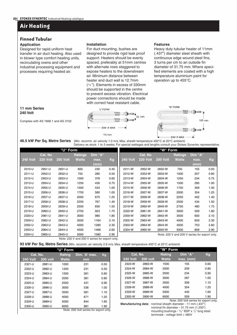
Finned TubularApplicationDesigned for rapid uniform heat transfer in air duct heating. Also used in blower type comfort heating units, recirculating ovens and other industrial processing equipment and processes requiring heated air.
InstallationFor duct mounting, bushes are designed to provide rigid leak proof support. Heaters should be evenly spaced, preferably at 51mm centres with alternate rows staggered to expose heaters to the downstream air. Minimum distance between heater and duct wall is 12.7mm (1/2 ”). Elements in excess of 330mm should be supported in the centre to prevent excess vibration. Electrical power connections should be made with correct heat resistant cable.
FeaturesHeavy duty tubular heater of 11mm(.437”) diameter steel sheath with continuous edge wound steel fi ns, 3 turns per cm to an outside fi n diameter of 31.75 mm. Where speci-fi ed elements are coated with a high temperature aluminium paint for operation up to 455°C.
11 mm Series 240 Volt
Complies with AS 1668.1 and AS 3102
Manufacturing data: nominal sheath diameter - 11 mm (.437”) nominal fi n diameter - 31.75 mm (1.250”) mounting bushings - 3/8 ” BSP x 1/2” long steel terminals - voltage limit = 480V
46.5 kW Per Sq. Metre Series (Min. recomm. air velocity 1.0 m/s. Max. sheath temperature 400°C at 20°C ambient) Delivery ex stock: 1 to 3 weeks. For special wattages and lengths consult your Stokes Synertec representative.
93 kW Per Sq. Metre Series (Min. recomm. air velocity 2.8 m/s. Max. sheath temperature 400°C at 20°C ambient)
Note: 220 V and 200 V series for export only.
Note: 200 Volt series for export only.
Note: 200 Volt series for export only.
Cat. No Ratings Dim "A"240 Volt 220 Volt 200 Volt Watts max. Kg
(mm)2310-U 2951-U 2831-U 600 230 0.40
2311-U 2952-U 2832-U 750 280 0.50
2312-U 2953-U 2833-U 1000 378 0.60
2313-U 2954-U 2834-U 1250 430 0.75
2314-U 2955-U 2835-U 1500 534 1.00
2315-U 2956-U 2836-U 1750 580 1.00
2316-U 2957-U 2837-U 2000 670 1.25
2317-U 2958-U 2838-U 2250 767 1.40
2318-U 2959-U 2839-U 2500 830 1.50
2319-U 2960-U 2840-U 2750 923 1.75
2320-U 2961-U 2841-U 3000 980 1.80
2359-U 2962-U 2842-U 3500 1164 2.10
2302-U 2963-U 2843-U 4000 1280 2.30
2303-U 2964-U 2844-U 4500 1468 2.60
2304-U 2965-U 2845-U 5000 1580 2.90
"U" FormCat. No Ratings Dim "A"
240 Volt 220 Volt 200 Volt Watts max. Kg(mm)
2311-W 2952-W 2832-W 750 155 0.50
2312-W 2353-W 2833-W 1000 207 0.60
2313-W 2954-W 2834-W 1250 234 0.75
2314-W 2955-W 2835-W 1500 285 1.00
2315-W 2956-W 2836-W 1750 309 1.00
2316-W 2957-W 2837-W 2000 354 1.25
2317-W 2958-W 2838-W 2250 402 1.40
2318-W 2959-W 2839-W 2500 434 1.50
2319-W 2960-W 2840-W 2750 480 1.75
2320-W 2961-W 2841-W 3000 509 1.80
2359-W 2962-W 2842-W 3500 600 2.10
2302-W 2963-W 2843-W 4000 659 2.30
2303-W 2964-W 2844-W 4500 753 2.60
2304-W 2965-W 2845-W 5000 809 2.90
"W" Form
Rating Dim. 'A' max. Kg
240 Volt 200 volt Watts mm2321-U 2881-U 1000 231 0.50
2322-U 2882-U 1200 231 0.50
2323-U 2883-U 1500 281 0.60
2324-U 2884-U 2000 381 0.80
2325-U 2885-U 2500 431 0.90
2326-U 2886-U 3000 536 1.00
2327-U 2887-U 3500 581 1.10
2328-U 2888-U 4000 671 1.25
2329-U 2889-U 5000 844 1.60
2305-U 2890-U 6000 981 1.90
"U" FormCat. No. Rating Dim "A" Kg
240 Volt 200 volt Watts max. (mm)2323-W 2883-W 1500 155 0.60
2324-W 2884-W 2000 209 0.80
2325-W 2885-W 2500 234 0.90
2326-W 2886-W 3000 287 1.00
2327-W 2887-W 3500 309 1.10
2328-W 2888-W 4000 354 1.25
2329-W 2889-W 5000 440 1.60
2305-W 2890-W 6000 509 1.90
"W" FormCat. No.
+10 mm-
Note: 220 V and 200 V series for export only.
55165
21STOKES SYNERTEC Industrial Heating catalogue
Air Heating
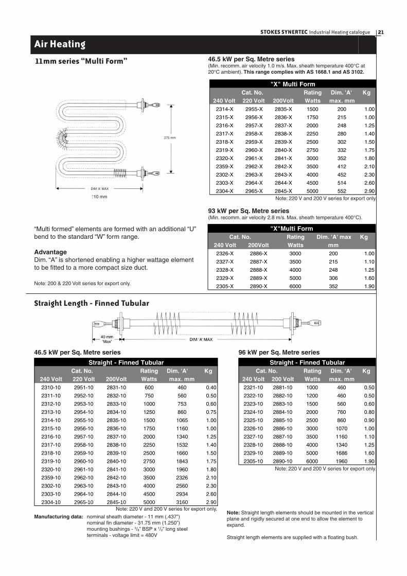
11mm series “Multi Form” 46.5 kW per Sq. Metre series (Min. recomm. air velocity 1.0 m/s. Max. sheath temperature 400°C at 20°C ambient). This range complies with AS 1668.1 and AS 3102.
93 kW per Sq. Metre series (Min. recomm. air velocity 2.8 m/s. Max. sheath temperature 400°C).
“Multi formed” elements are formed with an additional “U” bend to the standard “W” form range.
AdvantageDim. “A” is shortened enabling a higher wattage element to be fi tted to a more compact size duct.
Note: 200 & 220 Volt series for export only.
Straight Length - Finned Tubular
Note: Straight length elements should be mounted in the vertical plane and rigidly secured at one end to allow the element to expand.
Straight length elements are supplied with a fl oating bush.
Manufacturing data: nominal sheath diameter - 11 mm (.437”) nominal fi n diameter - 31.75 mm (1.250”) mounting bushings - 3/8” BSP x 1/2” long steel terminals - voltage limit = 480V
46.5 kW per Sq. Metre series 96 kW per Sq. Metre series
DIM ‘A’ MAX
275 mm
Rating Kg240 Volt 220 Volt 200Volt Watts max. mm2314-X 2955-X 2835-X 1500 200 1.00
2315-X 2956-X 2836-X 1750 215 1.00
2316-X 2957-X 2837-X 2000 248 1.25
2317-X 2958-X 2838-X 2250 280 1.40
2318-X 2959-X 2839-X 2500 302 1.50
2319-X 2960-X 2840-X 2750 332 1.75
2320-X 2961-X 2841-X 3000 352 1.80
2359-X 2962-X 2842-X 3500 412 2.10
2302-X 2963-X 2843-X 4000 452 2.30
2303-X 2964-X 2844-X 4500 514 2.60
2304-X 2965-X 2845-X 5000 552 2.90
"X" Multi FormDim. 'A' Cat. No.
Rating Kg240 Volt 200Volt Watts mm2326-X 2886-X 3000 200 1.00
2327-X 2887-X 3500 215 1.10
2328-X 2888-X 4000 248 1.25
2329-X 2889-X 5000 306 1.60
2305-X 2890-X 6000 352 1.90
Dim. 'A' maxCat. No. "X"Multi Form
Rating Kg240 Volt 220 Volt 200Volt Watts max. mm2310-10 2951-10 2831-10 600 460 0.40
2311-10 2952-10 2832-10 750 560 0.50
2312-10 2953-10 2833-10 1000 753 0.60
2313-10 2954-10 2834-10 1250 860 0.75
2314-10 2955-10 2835-10 1500 1065 1.00
2315-10 2956-10 2836-10 1750 1160 1.00
2316-10 2957-10 2837-10 2000 1340 1.25
2317-10 2958-10 2838-10 2250 1532 1.40
2318-10 2959-10 2839-10 2500 1660 1.50
2319-10 2960-10 2840-10 2750 1843 1.75
2320-10 2961-10 2841-10 3000 1960 1.80
2359-10 2962-10 2842-10 3500 2326 2.10
2302-10 2963-10 2843-10 4000 2560 2.30
2303-10 2964-10 2844-10 4500 2934 2.60
2304-10 2965-10 2845-10 5000 3160 2.90
Straight - Finned TubularDim. 'A' Cat. No. Rating Kg
240 Volt 200 Volt Watts max. mm2321-10 2881-10 1000 460 0.50
2322-10 2882-10 1200 460 0.50
2323-10 2883-10 1500 560 0.60
2324-10 2884-10 2000 760 0.80
2325-10 2885-10 2500 860 0.90
2326-10 2886-10 3000 1070 1.00
2327-10 2887-10 3500 1160 1.10
2328-10 2888-10 4000 1340 1.25
2329-10 2889-10 5000 1686 1.60
2305-10 2890-10 6000 1960 1.90
Straight - Finned TubularDim. 'A' Cat. No.
+10 mm- Note: 220 V and 200 V series for export only.
Note: 220 V and 200 V series for export only.
Note: 220 V and 200 V series for export only.

STOKES SYNERTEC Industrial Heating catalogue22
Air Heating
Finned Tubular 8mm series
31 kW per Sq. Metre Series Air heater element - fi nned tubular - painted20 Watts per square inch seriesTube diameter 8mm/ outside diameter 22mmComplies with AS 1668.1 and AS 3102
108 kW per Sq. Metre Series Air heater element - fi nned tubular - painted70 Watts per square inch seriesTube diameter 8mm/ outside diameter 22mm
50 mm
156 mm
240 Volt 220 Volt 200 Volt Watts "A" Dim. Kg
2761-U 2991-U 2921-U 500 380 0.46
2762-U 2992-U 2922-U 750 533 0.65
2763-U 2993-U 2923-U 1000 710 0.85
2764-U 2994-U 2924-U 1500 1010 1.10
2765-U 2995-U 2925-U 1800 1200 1.20
2766-U 2996-U 2926-U 2000 1327 1.50
2767-U 2997-U 2927-U 2400 1580 1.60
2761-W 2991-W 2921-W 500 200 0.46
2762-W 2992-W 2922-W 750 280 0.65
2763-W 2993-W 2923-W 1000 368 0.85
2764-W 2994-W 2924-W 1500 520 1.10
2765-W 2995-W 2925-W 1800 616 1.20
2766-W 2996-W 2926-W 2000 680 1.50
2767-W 2997-W 2927-W 2400 806 1.60
2762-X 2992-X 2922-X 750 200 0.65
2763-X 2993-X 2923-X 1000 260 0.85
2764-X 2994-X 2924-X 1500 360 1.10
2765-X 2995-X 2925-X 1800 424 1.20
2766-X 2996-X 2926-X 2000 467 1.50
2767-X 2997-X 2957-X 2400 550 1.60
2761-10 2991-10 2921-10 500 760 0.46
2762-10 2992-10 2922-10 750 1065 0.65
2763-10 2993-10 2923-10 1000 1425 0.85
2764-10 2994-10 2924-10 1500 2017 1.10
2765-10 2995-10 2925-10 1800 2398 1.20
2766-10 2996-10 2926-10 2000 2652 1.50
2767-10 2997-10 2927-10 2400 3160 1.60
Straight Elements
"X" Multi Form
Air Heating Elements-Finned Tubular
"U" Form
'W" Form
Cat. No.
240 Volt 220 Volt 200 Volt Watts "A" Dim. Kg
3321-U 2971-U 2981-U 600 210 0.26
3322-U 2972-U 2982-U 900 222 0.27
3323-U 2973-U 2983-U 1200 273 0.28
3324-U 2974-U 2984-U 1500 330 0.35
3325-U 2975-U 2985-U 1800 380 0.46
3326-U 2976-U 2986-U 2000 420 0.52
3327-U 2977-U 2987-U 2400 495 0.56
3328-U 2978-U 2988-U 3000 603 0.65
3329-U 2979-U 2989-U 3600 711 0.87
3330-U 2980-U 2990-U 4800 915 0.99
3320-U 2940-U 2950-U 6000 1175 1.30
3323-W 2973-W 2983-W 1200 153 0.28
3324-W 2974-W 2984-W 1500 180 0.35
3325-W 2975-W 2985-W 1800 200 0.46
3326-W 2976-W 2986-W 2000 222 0.52
3327-W 2977-W 2987-W 2400 260 0.26
3328-W 2978-W 2988-W 3000 315 0.65
3329-W 2979-W 2989-W 3600 368 0.81
3330-W 2980-W 2990-W 4800 476 0.99
3320-W 2940-W 2950-W 6000 600 1.30
3328-X 2978-X 2988-X 3000 220 0.65
3329-X 2979-X 2989-X 3600 260 0.81
3330-X 2980-X 2990-X 4800 329 0.99
3320-X 2940-X 2950-X 6000 417 1.30
3321-10 2971-10 2981-10 600 440 0.26
3322-10 2972-10 2982-10 900 440 0.27
3323-10 2973-10 2983-10 1200 544 0.28
3324-10 2974-10 2984-10 1500 658 0.35
3325-10 2975-10 2985-10 1800 760 0.46
3326-10 2976-10 2986-10 2000 836 0.52
3327-10 2977-10 2987-10 2400 988 0.56
3328-10 2978-10 2988-10 3000 1204 0.65
3329-10 2979-10 2989-10 3600 1420 0.87
3330-10 2980-10 2990-10 4800 1852 0.99
3320-10 2940-10 2950-10 6000 2350 1.30
Air Heating Elements-Finned Tubular
Straight Elements
'X" Multi Form
'W" Form
"U" Form
Cat. No.
DIM ‘A’ MAX
260 mm
“X” MULTI FORM
+10 mm-
+10 mm-
+10 mm-+10 mm-
Note: 220 / 200V for export only
23STOKES SYNERTEC Industrial Heating catalogue
Air Heating
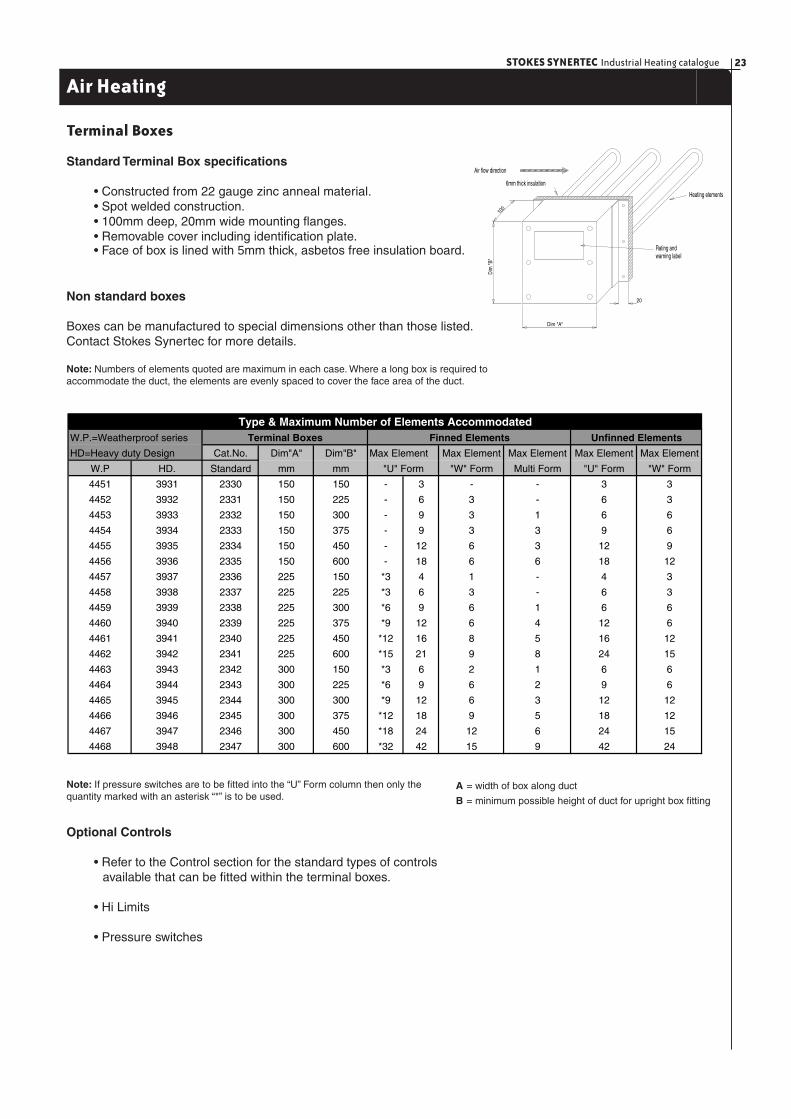
Terminal Boxes
Standard Terminal Box specifi cations
• Constructed from 22 gauge zinc anneal material. • Spot welded construction. • 100mm deep, 20mm wide mounting fl anges. • Removable cover including identifi cation plate.
• Face of box is lined with 5mm thick, asbetos free insulation board.
Non standard boxes
Boxes can be manufactured to special dimensions other than those listed. Contact Stokes Synertec for more details.
Note: Numbers of elements quoted are maximum in each case. Where a long box is required to accommodate the duct, the elements are evenly spaced to cover the face area of the duct.
Note: If pressure switches are to be fi tted into the “U” Form column then only the quantity marked with an asterisk “*” is to be used.
A = width of box along duct
B = minimum possible height of duct for upright box fi tting
Optional Controls
• Refer to the Control section for the standard types of controls available that can be fi tted within the terminal boxes.
• Hi Limits
• Pressure switches
W.P.=Weatherproof series
Cat.No. Dim"A" Dim"B" Max Element Max Element Max Element Max Element Max Element
W.P HD. Standard mm mm "W" Form Multi Form "U" Form "W" Form
4451 3931 2330 150 150 - 3 - - 3 3
4452 3932 2331 150 225 - 6 3 - 6 3
4453 3933 2332 150 300 - 9 3 1 6 6
4454 3934 2333 150 375 - 9 3 3 9 6
4455 3935 2334 150 450 - 12 6 3 12 9
4456 3936 2335 150 600 - 18 6 6 18 12
4457 3937 2336 225 150 *3 4 1 - 4 3
4458 3938 2337 225 225 *3 6 3 - 6 3
4459 3939 2338 225 300 *6 9 6 1 6 6
4460 3940 2339 225 375 *9 12 6 4 12 6
4461 3941 2340 225 450 *12 16 8 5 16 12
4462 3942 2341 225 600 *15 21 9 8 24 15
4463 3943 2342 300 150 *3 6 2 1 6 6
4464 3944 2343 300 225 *6 9 6 2 9 6
4465 3945 2344 300 300 *9 12 6 3 12 12
4466 3946 2345 300 375 *12 18 9 5 18 12
4467 3947 2346 300 450 *18 24 12 6 24 15
4468 3948 2347 300 600 *32 42 15 9 42 24
Type & Maximum Number of Elements Accommodated
HD=Heavy duty Design
"U" Form
Terminal Boxes Finned Elements Unfinned Elements
warning labelRating and
Heating elements
6mm thick insulation
Air flow direction
100
20
Dim "A"
Dim
"B"

STOKES SYNERTEC Industrial Heating catalogue24
Air Heating
Duct Heater Selection Tables
Comprising: Low Temperature Finned Elements (Commonly termed as Black Heat Elements)Maximum sheath temperature: 400°C in still air at 20°C ambient.Elements: 240 voltsIncludes: 6mm thick insulation on terminal box face.All units suitable for connection to 3 phase 415/240 volt 4 wire supply.Specifi cation delivery: 10 to 15 workings days.Maximum operating air temperature: 100°C (for higher operating temperatures contact Stokes
Synertec)
Note: non standard units manufactured to clients requirements. When ordering specify catalogue number, quantity, wattage and type of over temperature protection (if required).
This range complies with AS1668.1 and AS3102
Compact Duct Assemblies
Cat.No. Kw Min. Duct Size Elements Terminal Min. Air
Wmm x Hmm Box Flow m3/sLF 24 15.0 400 x 450 15 2312 U 2340 0.180
LF 25 22.5 560 x 450 15 2314 U 2340 0.252
LF 26 30.0 700 x 450 15 2316 U 2340 0.315
LF 27 37.5 900 x 450 15 2318 U 2340 0.405
LF 28 45.0 1000 x 450 15 2320 U 2340 0.450
LF 29 60.0 1300 x 450 15 2302 U 2340 0.585
LF 30 18.0 400 x 600 18 2312 U 2341 0.240
LF 31 27.0 560 x 600 18 2314 U 2341 0.336
LF 32 36.0 700 x 600 18 2316 U 2341 0.420
LF 33 45.0 900 x 600 18 2318 U 2341 0.540
LF 34 54.0 1000 x 600 18 2320 U 2341 0.600
LF 35 72.0 1300 x 600 18 2302 U 2341 0.780
Elements
No. of
Cat.No. Kw Min. Duct Size Elements Terminal Min. Air
Wmm x Hmm Box Flow m3/sLF 36 1 220 x 150 1 2312 W 2336 0.030
LF 37 2 220 x 225 2 2312 W 2331 0.045
LF 38 3 220 x 225 3 2312 W 2337 0.045
LF 39 6 400 x 225 3 2316 W 2337 0.090
LF 40 9 540 x 225 3 2320 W 2337 0.122
LF 41 12 400 x 300 6 2316 W 2344 0.120
LF 42 15 480 x 300 6 2318 W 2344 0.144
LF 43 18 550 x 300 6 2320 W 2344 0.165
LF 44 24 700 x 300 6 2302 W 2344 0.210
LF 45 27 550 x 450 9 2320 W 2346 0.248
Elements
No. of
Cat.No. Kw Min. Duct Size Elements Terminal Min. Air
Wmm x Hmm Box Flow m3/sLF 1 1.0 400 x 150 1 2312 U 2330 0.060
LF 2 2.0 400 x 150 2 2312 U 2330 0.060
LF 3 3.0 400 x 150 3 2312 U 2330 0.060
LF 4 4.5 560 x 150 3 2314 U 2330 0.084
LF 5 6.0 700 x 150 3 2316 U 2330 0.105
LF 6 7.5 900 x 150 3 2318 U 2330 0.135
LF 7 3.0 400 x 225 3 2312 U 2331 0.090
LF 8 6.0 400 x 225 6 2312 U 2331 0.090
LF 9 9.0 560 x 225 6 2314 U 2331 0.126
LF 10 12.0 700 x 225 6 2316 U 2331 0.158
LF 11 15.0 900 x 225 6 2318 U 2331 0.203
LF 12 5.4 250 x 300 9 2310 U 2338 0.075
LF 13 9.0 400 x 300 9 2312 U 2338 0.120
LF 14 13.5 560 x 300 9 2314 U 2338 0.168
LF 15 18.0 700 x 300 9 2316 U 2338 0.210
LF 16 22.5 900 x 300 9 2318 U 2338 0.270
LF 17 27.0 1000 x 300 9 2320 U 2338 0.300
LF 18 12.0 400 x 375 12 2312 U 2339 0.150
LF 19 18.0 560 x 375 12 2314 U 2339 0.210
LF 20 24.0 700 x 375 12 2316 U 2339 0.263
LF 21 30.0 900 x 375 12 2318 U 2339 0.340
LF 22 36.0 1000 x 375 12 2320 U 2339 0.375
LF 23 48.0 1300 x 375 12 2302 U 2339 0.488
Elements
No. of
25STOKES SYNERTEC Industrial Heating catalogue
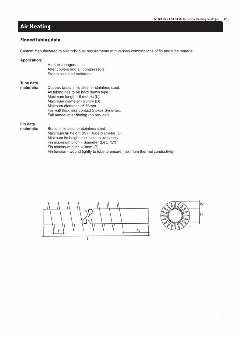
Finned tubing data
Custom manufactured to suit individual requirements with various combinations of fi n and tube material.
Application: Heat exchangers After coolers and air compressors Steam coils and radiators
Tube data materials: Copper, brass, mild steel or stainless steel. All tubing has to be hard drawn type. Maximum length - 6 metres (L) Maximum diameter - 20mm (D) Minimum diameter - 6.53mm For wall thickness contact Stokes Synertec. Full anneal after fi nning (on request)
Fin data materials: Brass, mild steel or stainless steel. Maximum fi n height (W) = tube diameter (D) Minimum fi n height is subject to availabilty Fin maximum pitch = diameter (D) x 75% Fin mimimum pitch = 3mm (P) Fin tension - wound tightly to tube to ensure maximum thermal conductivity.
Air Heating
STOKES SYNERTEC Industrial Heating catalogue26
Radiant Infra-red Heaters (Ceramic)
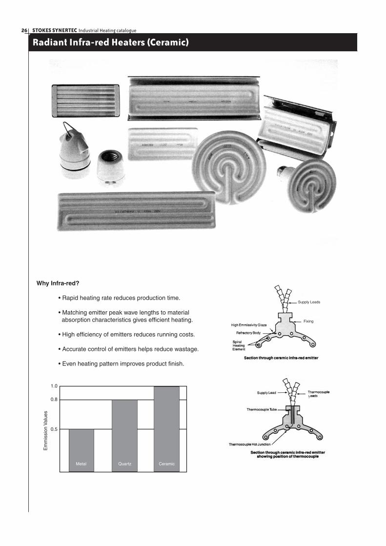
Why Infra-red?
• Rapid heating rate reduces production time.
• Matching emitter peak wave lengths to material absorption characteristics gives effi cient heating.
• High effi ciency of emitters reduces running costs.
• Accurate control of emitters helps reduce wastage.
• Even heating pattern improves product fi nish.
Em
mis
sion
Val
ues
0.5
0.8
1.0
Metal Quartz Ceramic
Supply Leads
Fixing
27STOKES SYNERTEC Industrial Heating catalogue
Radiant Infra-red Heaters (Ceramic)
Application Data
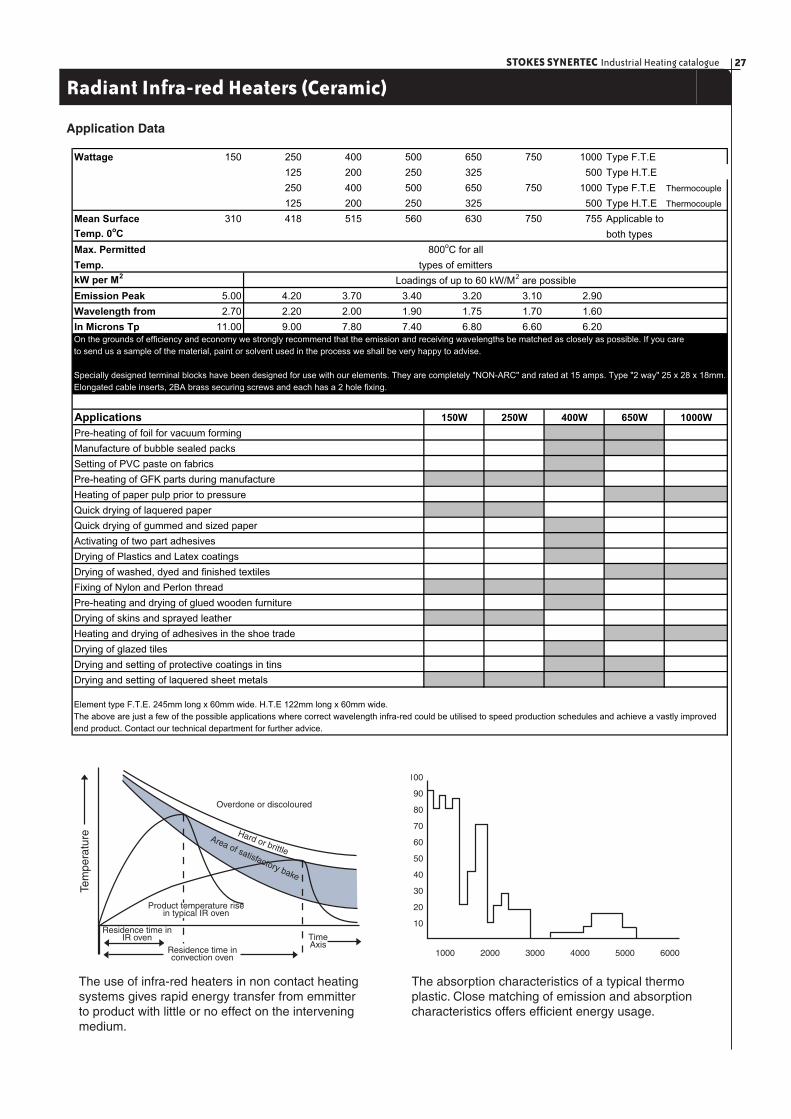
The use of infra-red heaters in non contact heating systems gives rapid energy transfer from emmitter to product with little or no effect on the intervening medium.
The absorption characteristics of a typical thermo plastic. Close matching of emission and absorption characteristics offers effi cient energy usage.
Wattage 150 250 400 500 650 750 1000 Type F.T.E
125 200 250 325 500 Type H.T.E
250 400 500 650 750 1000 Type F.T.E Thermocouple
125 200 250 325 500 Type H.T.E Thermocouple
Mean Surface 310 418 515 560 630 750 755 Applicable to
Temp. 0oC both types
Max. Permitted
Temp.
kW per M2
Emission Peak 5.00 4.20 3.70 3.40 3.20 3.10 2.90
Wavelength from 2.70 2.20 2.00 1.90 1.75 1.70 1.60
In Microns Tp 11.00 9.00 7.80 7.40 6.80 6.60 6.20
150W 250W 400W 650W 1000W
800oC for all
types of emitters
Loadings of up to 60 kW/M2 are possible
On the grounds of efficiency and economy we strongly recommend that the emission and receiving wavelengths be matched as closely as possible. If you care
to send us a sample of the material, paint or solvent used in the process we shall be very happy to advise.
Specially designed terminal blocks have been designed for use with our elements. They are completely "NON-ARC" and rated at 15 amps. Type "2 way" 25 x 28 x 18mm.
Elongated cable inserts, 2BA brass securing screws and each has a 2 hole fixing.
Applications
Pre-heating of foil for vacuum forming
Manufacture of bubble sealed packs
Setting of PVC paste on fabrics
Pre-heating of GFK parts during manufacture
Heating of paper pulp prior to pressure
Quick drying of laquered paper
Quick drying of gummed and sized paper
Activating of two part adhesives
Drying of Plastics and Latex coatings
Drying of washed, dyed and finished textiles
Fixing of Nylon and Perlon thread
Pre-heating and drying of glued wooden furniture
Drying of skins and sprayed leather
Heating and drying of adhesives in the shoe trade
The above are just a few of the possible applications where correct wavelength infra-red could be utilised to speed production schedules and achieve a vastly improved
end product. Contact our technical department for further advice.
Drying of glazed tiles
Drying and setting of protective coatings in tins
Drying and setting of laquered sheet metals
Element type F.T.E. 245mm long x 60mm wide. H.T.E 122mm long x 60mm wide.
Tem
pera
ture
Residence time inconvection oven
Residence time inIR oven Time
Axis
Overdone or discoloured
Hard or brittleArea of satisfactory bake
Product temperature risein typical IR oven
100
90
80
70
60
50
40
30
20
10
1000 2000 3000 4000 5000 6000
STOKES SYNERTEC Industrial Heating catalogue28
Radiant Infra-red Heaters (Ceramic)
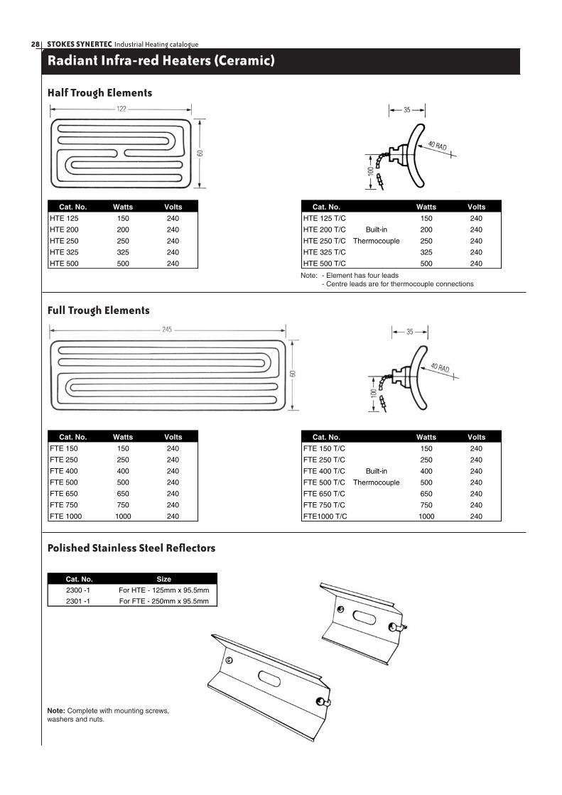
Half Trough Elements
Cat. No. Watts Volts
HTE 125 150 240
HTE 200 200 240
HTE 250 250 240
HTE 325 325 240
HTE 500 500 240
Cat. No. Watts Volts
HTE 125 T/C 150 240
HTE 200 T/C Built-in 200 240
HTE 250 T/C Thermocouple 250 240
HTE 325 T/C 325 240
HTE 500 T/C 500 240
Full Trough Elements
Cat. No. Watts Volts
FTE 150 150 240
FTE 250 250 240
FTE 400 400 240
FTE 500 500 240
FTE 650 650 240
FTE 750 750 240
FTE 1000 1000 240
Cat. No. Watts Volts
FTE 150 T/C 150 240
FTE 250 T/C 250 240
FTE 400 T/C Built-in 400 240
FTE 500 T/C Thermocouple 500 240
FTE 650 T/C 650 240
FTE 750 T/C 750 240
FTE1000 T/C 1000 240
Polished Stainless Steel Refl ectors
Note: Complete with mounting screws, washers and nuts.
Note: - Element has four leads - Centre leads are for thermocouple connections
Cat. No. Size
2300 -1 For HTE - 125mm x 95.5mm
2301 -1 For FTE - 250mm x 95.5mm
29STOKES SYNERTEC Industrial Heating catalogue
Radiant Infra-red Heaters (Ceramic)
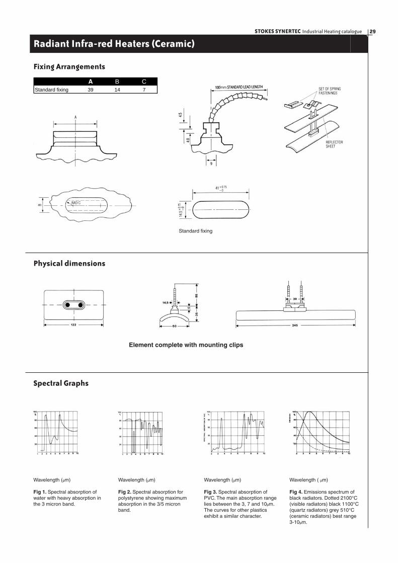
Fixing Arrangements
Standard fi xing
Physical dimensions
Element complete with mounting clips
Spectral Graphs
Wavelength (µm)
Fig 1. Spectral absorption of water with heavy absorption in the 3 micron band.
Wavelength (µm)
Fig 2. Spectral absorption for polystyrene showing maximum absorption in the 3/5 micron band.
Wavelength (µm)
Fig 3. Spectral absorption of PVC. The main absorption range lies between the 3, 7 and 10µm. The curves for other plastics exhibit a similar character.
Wavelength ( µm)
Fig 4. Emissions spectrum of black radiators. Dotted 2100°C (visible radiators) black 1100°C (quartz radiators) grey 510°C (ceramic radiators) best range 3-10µm.
40
20
60
80
100
%
40
20
60
80
100%
A B CStandard fixing 39 14 7 mm
STOKES SYNERTEC Industrial Heating catalogue30
Radiant Infra-red Heaters (Ceramic)
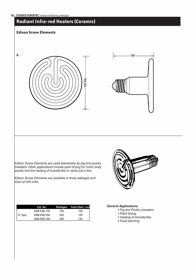
Edison Screw Elements
A
Edison Screw Elements are used extensively by pig and poultry breeders. Other applications include paint drying for motor body panels and the heating of humidicribs to name just a few.
Edison Screw Elements are available in three wattages and sizes at 240 volts.
General Applications • Pig and Poultry breeders • Paint drying • Heating of Humidicribs • Food warming
Cat. No. Wattages Face Diam. mm
2306 ESE 150 150 125
"A" type 2306 ESE 250 250 125
2306 ESE 500 500 125

31STOKES SYNERTEC Industrial Heating catalogue
Radiant Infra-red Heaters (Ceramic - Optional Parts)
Screw Holder
Suspension typeCat. No 9209
Refl ectors
Two way Ceramic Block
Cat. No 9324 Cat. No 9325
Cat. No. Size
2300-15 40mm.longx20mm.highx32mm.wide
Solid State Controls Energy Regulator
Cat. No. PN4AIC-M 0800 K0-800°C
Cat. No. PF4AIC-M 0800 K0-800°C
Non indicating type Indicating type Cat. No. TYJ6333 13 Amp. rating
Note: A complete range of Digital Temperature Controllers and Thermocouples are available on customer request. Please contact Stokes Synertecfor more details.
2 - way 15ampStainless Steel
STOKES SYNERTEC Industrial Heating catalogue32
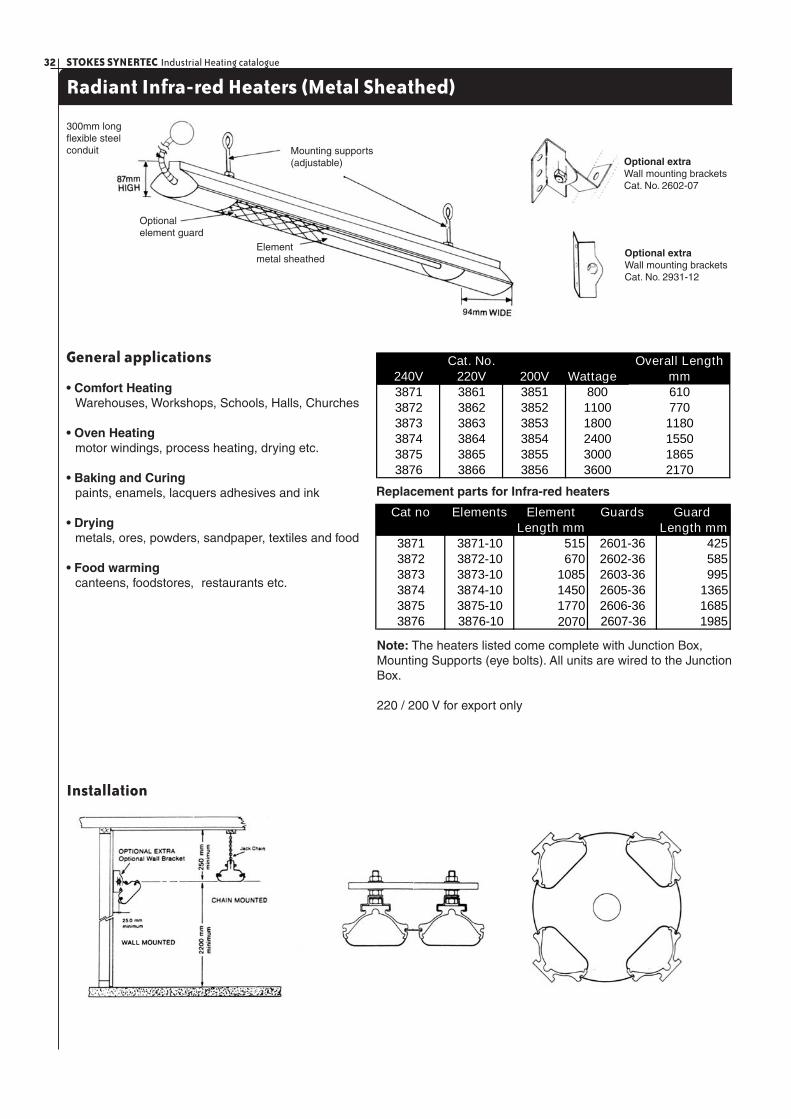
Radiant Infra-red Heaters (Metal Sheathed)
General applications
• Comfort Heating Warehouses, Workshops, Schools, Halls, Churches
• Oven Heating motor windings, process heating, drying etc.
• Baking and Curing paints, enamels, lacquers adhesives and ink
• Drying metals, ores, powders, sandpaper, textiles and food
• Food warming canteens, foodstores, restaurants etc.
240V 220V 200V3871 3861 3851 8003872 3862 3852 11003873 3863 3853 18003874 3864 3854 24003875 3865 3855 30003876 3866 3856 3600
6107701180155018652170
Cat. No.Wattage
Overall Lengthmm
Cat no Elements Element Guards Guard Length mm Length mm
3871 3871-10 515 2601-36 4253872 3872-10 670 2602-36 5853873 3873-10 1085 2603-36 9953874 3874-10 1450 2605-36 13653875 3875-10 1770 2606-36 1685
19853876 3876-10 2070 2607-36
Replacement parts for Infra-red heaters
Note: The heaters listed come complete with Junction Box, Mounting Supports (eye bolts). All units are wired to the Junction Box.
220 / 200 V for export only
Mounting supports (adjustable)
Optionalelement guard
Element metal sheathed
300mm longfl exible steelconduit
Optional extraWall mounting bracketsCat. No. 2602-07
Optional extraWall mounting bracketsCat. No. 2931-12
Installation
33STOKES SYNERTEC Industrial Heating catalogue
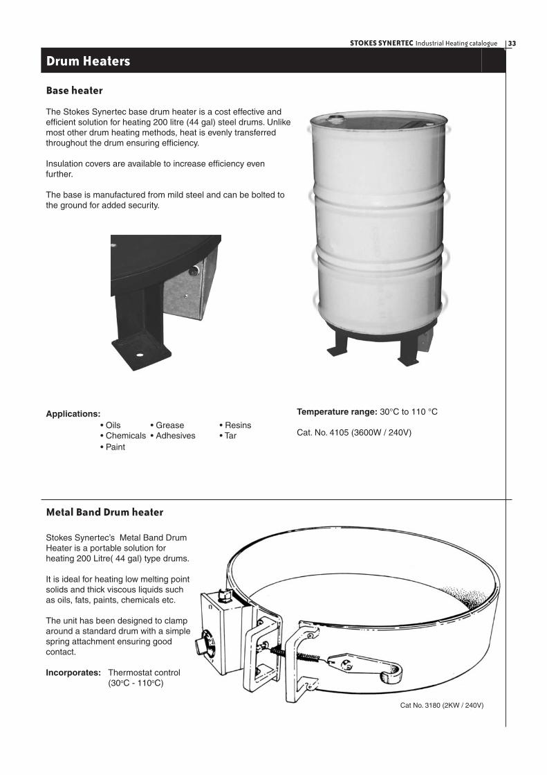
Drum Heaters
Base heater
The Stokes Synertec base drum heater is a cost effective and effi cient solution for heating 200 litre (44 gal) steel drums. Unlike most other drum heating methods, heat is evenly transferred throughout the drum ensuring effi ciency.
Insulation covers are available to increase effi ciency even further.
The base is manufactured from mild steel and can be bolted to the ground for added security.
Applications: • Oils • Grease • Resins • Chemicals • Adhesives • Tar • Paint
Temperature range: 30°C to 110 °C
Cat. No. 4105 (3600W / 240V)
Metal Band Drum heater
Stokes Synertec’s Metal Band Drum Heater is a portable solution for heating 200 Litre( 44 gal) type drums.
It is ideal for heating low melting point solids and thick viscous liquids such as oils, fats, paints, chemicals etc.
The unit has been designed to clamp around a standard drum with a simple spring attachment ensuring good contact.
Incorporates: Thermostat control (30oC - 110oC)
Cat No. 3180 (2KW / 240V)
STOKES SYNERTEC Industrial Heating catalogue34
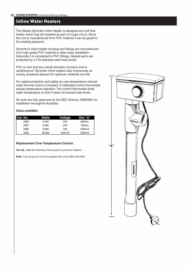
Inline Water Heaters
The Stokes Synertec Inline Heater is designed as a full fl ow heater which may be installed as part of a pipe circuit. Since the unit is manufactured from PVC material it can be glued to the existing pipework.
Synertec’s inline heater housing and fi ttings are manufactured from high grade PVC material to allow easy installation. Generally it is connected to PVC fi ttings. Heated parts are protected by a 316 stainless steel heat shield.
PVC is inert and as a result elimates corrosion and is weatherproof. Synertec inline heaters also incorporate an incoloy sheathed element for optimum reliability and life.
For added protection and safety an over-temperature manual reset thermal cutout is included. A calibrated control thermostat assists temperature selection. The control thermostat limits water temperature so that it does not exceed safe levels.
All units are fully approved by the SEC Victoria, DS8208V, for installation throughout Australia.
Sizes available:
Replacement Over Temperature Control:
Cat. No. 2360-36 Overtemp Thermostat to suit Inline Heaters.
Note: 3 pin plug and cord not supplied with units 2362 and 2363.
Cat. No. Watts Voltage Dim "A"2360 2,400 240 665mm
2361 3,000 240 730mm
2362 6,000 240 1000mm
2363 30,000 240/415 1250mm
“A”
35STOKES SYNERTEC Industrial Heating catalogue
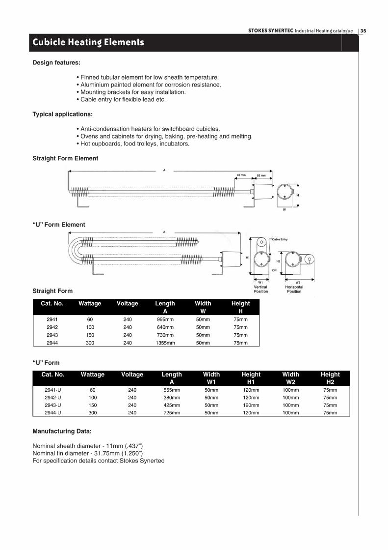
Design features:
• Finned tubular element for low sheath temperature. • Aluminium painted element for corrosion resistance. • Mounting brackets for easy installation. • Cable entry for fl exible lead etc.
Typical applications:
• Anti-condensation heaters for switchboard cubicles. • Ovens and cabinets for drying, baking, pre-heating and melting. • Hot cupboards, food trolleys, incubators.
Straight Form Element
“U” Form Element
Straight Form
Cubicle Heating Elements
Cat. No. Wattage Voltage Length Width HeightA W H
2941 60 240 995mm 50mm 75mm
2942 100 240 640mm 50mm 75mm
2943 150 240 730mm 50mm 75mm
2944 300 240 1355mm 50mm 75mm
“U” Form
Cat. No. Wattage Voltage Length Width Height Width HeightA W1 H1 W2 H2
2941-U 60 240 555mm 50mm 120mm 100mm 75mm
2942-U 100 240 380mm 50mm 120mm 100mm 75mm
2943-U 150 240 425mm 50mm 120mm 100mm 75mm
2944-U 300 240 725mm 50mm 120mm 100mm 75mm
Manufacturing Data:
Nominal sheath diameter - 11mm (.437”)Nominal fi n diameter - 31.75mm (1.250”)For specifi cation details contact Stokes Synertec
W2
W
W1
STOKES SYNERTEC Industrial Heating catalogue36
Controls - General Information
General Information
An effective control system cannot simply depend on the sensitivity of the control itself. *Three major factors infl uence the controllability of the entire system:
Temperature differences throughout the system should be minimized. Pumping or agitating a liquid, particularly a viscous one, helps reduce temperature variations. Temperature uniformity in solids is achieved by spacing elements at frequent intervals and far enough away from the working surface to allow temperatures to even out; by choosing an element shape compatible with the shape of the solid (fl at heaters for fl at surfaces, curved strip heaters for cylinders, etc.); and by insulating exposed edges.
Thermal lag - The time between energizing the heaters and a temperature increase at any point in the system can cause overshoot and undershoot of control settings. Generally, a short thermal lag is desirable in order to produce a temperature rise quickly when the elements are turned on and a quick cooling effect when they are turned off. For liquids, agitating or pumping helps reduce thermal lag. For gases, forced circulation transfers heat more rapidly than does natural convection. Lightweight heating elements also cut down thermal lag. Thus open coil elements are often preferred to enclosed elements for oven heating applications. When heating solids, the overall mass of the system should be kept to a minimum. Materials such as aluminium are preferred because of their high thermal conductivity and low specifi c heat.
Often there must be a compromise between low thermal lag and good temperature uniformity - e.g. a massive platen tends to have a more uniform temperature over its face, but responds slowly when elements are turned on and off, resulting in long warm-up and cooling peri-ods. Good distribution of the heating source and proper choice of the control (see “Choosing The Right Controller) are essential in this situation.
Heating capacity, or installed wattage, should match the system requirements as closely as possible. Too little heat will of course produce temperatures that are too low. Conversely, if the system is designed with far more wattage than required, temperatures will overshoot and undershoot the control setting substantially as the heaters cycle on and off. Multi-stage controls can help correct this situation, but from the standpoint of economy, it is always better to choose the correct wattage and control it with a simple thermostat. Systems requiring substantially more heat initially than after the system is running should be designed with two or more stages of control. Control sensitivity is the inherent ability of the switching mechanism to respond to temperature changes in the sensing medium (liquid fi ll or bimetal). In practice a system is rarely controlled to within the limits of the control’s sensitivity, due to other factors in the system.
Choosing the right control
For most industrial applications, series 2370 is used because of its rugged construction, high load-carrying capacity, and simplicity of operation. When the capacity of series 2370 is exceeded the load must be switched on and off by a magnetic contactor.
Protective devices
Thermal cut-outs are thermostatic devices used to protect product or heater overheat by opening heater circuit(s) at a pre-set temperature above the control temperature in case of malfunctioning of some component in the system. They are wired in a series with control thermostat(s) and shut down the system if overheating occurs. Equipped with reset buttons, they must be reset manually to re-energise the heaters.
* Note:After system has been checked by authorised personnel to correct any
malfunctioning.
Placement of the sensing bulb near the work protects the product against overheat. Likewise, placement of bulb near the heat source protects the heaters. In heating systems where work is distant from the heaters, two cut-outs can be used, with one bulb placed near the work and the other near the heaters.
Low-liquid cut-offs are used in conjunction with immer-sion heaters to prevent heater burn-out due to low liquid levels. After liquid level is restored, the control is reset manually to re-energise the heater.
Other methods of control
Single and three-heat switches are used to manually control heating loads. Single-heat switches provide on-off control and may be used to operate the holding coil of a contactor for single-phase loads greater than the switch capacity, or for the three-phase loads. Three-heat switches used with two heating elements or circuits of equal rating provide low, medium and high heats. Controlling heater output by manually varying input volt-age is accomplished by means of a variable transformer. This is a precise method of control and permits exact matching of heat to work requirements.

37STOKES SYNERTEC Industrial Heating catalogue
Wiring Installation
Wiring Hints
It should always be remembered that wiring may be operating at high temperatures, although the ambient temperature is relatively low. This may be the result of conducted heat from heater termi-nals or radiation from heated surfaces.
Under these circumstances, or where ambient temperatures are high, special high temperature wiring should be used. This normally consists of high temperature nickel or alloy wire and heat-resistant insulation such as silicon and/or fi breglass.
Installing Heater Wiring
(a) All heater terminal connections should be fi rmly tightened as allowed by terminal strength. Where possible, terminals should be supported while tightening connections to prevent twisting of the terminals.
(b) Where the wire and terminals may be subjected to expan sion and contraction, causing movement of the wire, stranded wire is preferred. One way to compensate for this, is to leave liberal expansion loops between points of support in solid wire or small bus bar.
(c) Seperate conduit should be provided for thermocouple circuit wiring.
(d) Do not allow thermocouple wiring or capillary tubing of thermostat to approach heater terminals.
Fig.1 Single phase heater controlled by a single pole thermostat.
Fig.2 Single phase heater controlled through a magnetic contactor by a single pole thermostat.
Fig. 3 Three phase heater controlled through a magnetic contac-tor by a single pole thermostat.
Fig. 4 Single phase a-c or d-c or 3-phase a-c heater circuit. Dotted lines and L3 indicates 3 phase.
Fig. 5 Single phase a-c circuit with Type-TYJ energy regulator.
Fig. 6 Single phase a-c or d-c heater circuit with single-pole 3-heat switch.
Fig. 7 Single phase a-c or d-c heater circuit with double-pole 3-heat switch.
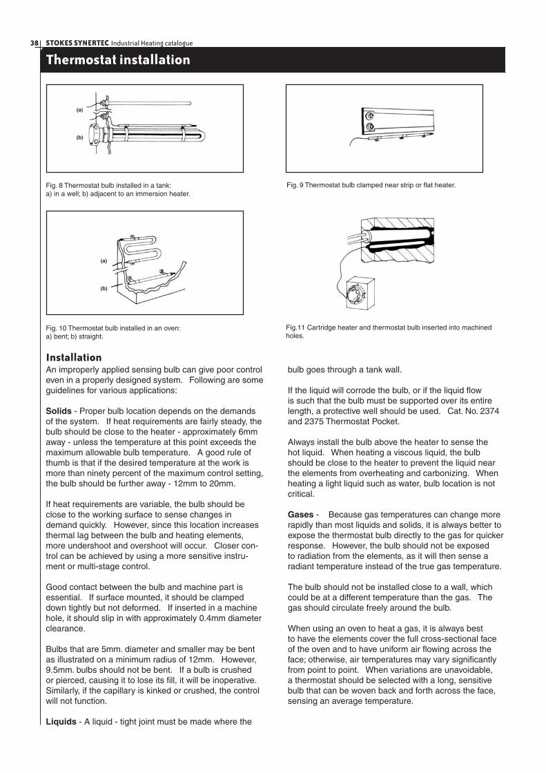
STOKES SYNERTEC Industrial Heating catalogue38
Thermostat installation
Fig. 8 Thermostat bulb installed in a tank:a) in a well; b) adjacent to an immersion heater.
Fig. 10 Thermostat bulb installed in an oven:a) bent; b) straight.
Fig. 9 Thermostat bulb clamped near strip or fl at heater.
Fig.11 Cartridge heater and thermostat bulb inserted into machined holes.
InstallationAn improperly applied sensing bulb can give poor control even in a properly designed system. Following are some guidelines for various applications:
Solids - Proper bulb location depends on the demands of the system. If heat requirements are fairly steady, the bulb should be close to the heater - approximately 6mm away - unless the temperature at this point exceeds the maximum allowable bulb temperature. A good rule of thumb is that if the desired temperature at the work is more than ninety percent of the maximum control setting, the bulb should be further away - 12mm to 20mm.
If heat requirements are variable, the bulb should be close to the working surface to sense changes in demand quickly. However, since this location increases thermal lag between the bulb and heating elements, more undershoot and overshoot will occur. Closer con-trol can be achieved by using a more sensitive instru-ment or multi-stage control.
Good contact between the bulb and machine part is essential. If surface mounted, it should be clamped down tightly but not deformed. If inserted in a machine hole, it should slip in with approximately 0.4mm diameter clearance.
Bulbs that are 5mm. diameter and smaller may be bent as illustrated on a minimum radius of 12mm. However, 9.5mm. bulbs should not be bent. If a bulb is crushed or pierced, causing it to lose its fi ll, it will be inoperative. Similarly, if the capillary is kinked or crushed, the control will not function.
Liquids - A liquid - tight joint must be made where the
bulb goes through a tank wall.
If the liquid will corrode the bulb, or if the liquid fl ow is such that the bulb must be supported over its entire length, a protective well should be used. Cat. No. 2374 and 2375 Thermostat Pocket.
Always install the bulb above the heater to sense the hot liquid. When heating a viscous liquid, the bulb should be close to the heater to prevent the liquid near the elements from overheating and carbonizing. When heating a light liquid such as water, bulb location is not critical.
Gases - Because gas temperatures can change more rapidly than most liquids and solids, it is always better to expose the thermostat bulb directly to the gas for quicker response. However, the bulb should not be exposed to radiation from the elements, as it will then sense a radiant temperature instead of the true gas temperature.
The bulb should not be installed close to a wall, which could be at a different temperature than the gas. The gas should circulate freely around the bulb.
When using an oven to heat a gas, it is always best to have the elements cover the full cross-sectional face of the oven and to have uniform air fl owing across the face; otherwise, air temperatures may vary signifi cantly from point to point. When variations are unavoidable, a thermostat should be selected with a long, sensitive bulb that can be woven back and forth across the face, sensing an average temperature.
(a)
(b)
(a)
(b)
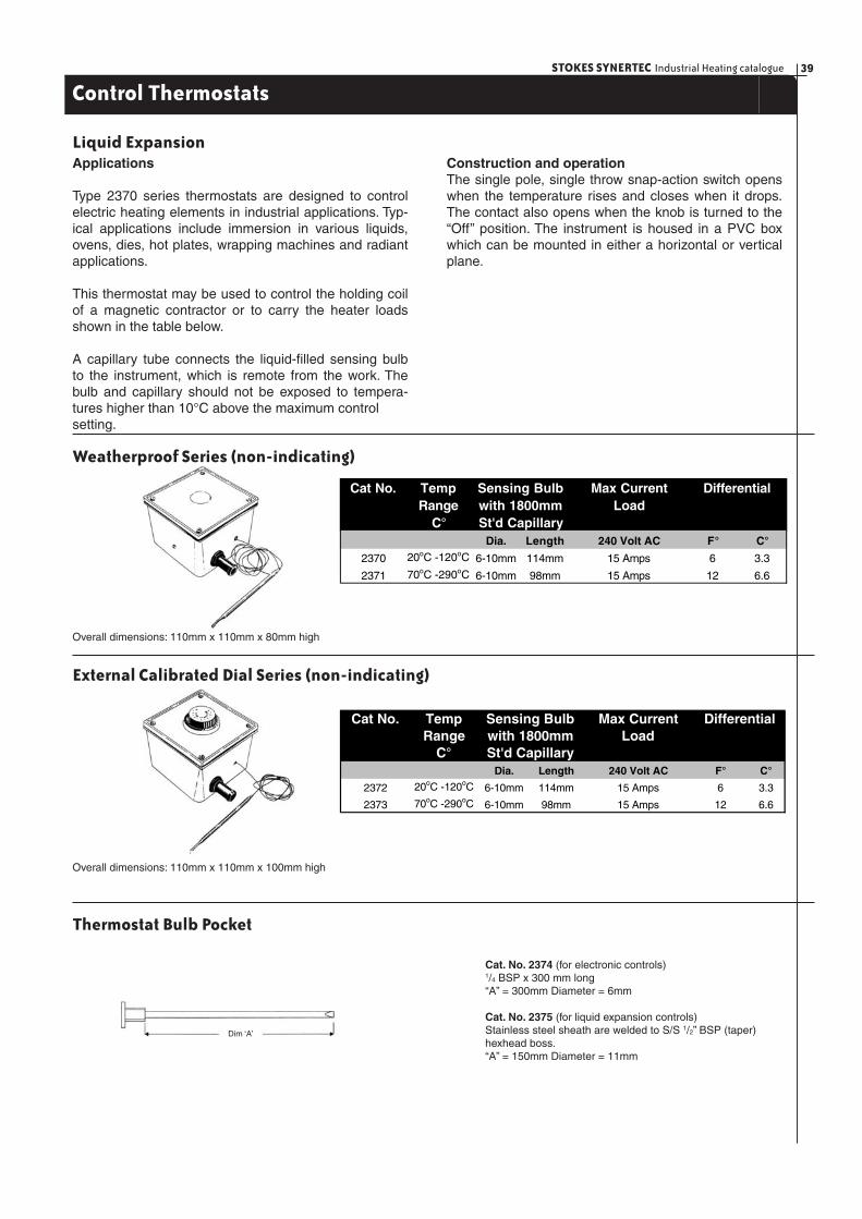
39STOKES SYNERTEC Industrial Heating catalogue
Control Thermostats
Applications
Type 2370 series thermostats are designed to control electric heating elements in industrial applications. Typ-ical applications include immersion in various liquids, ovens, dies, hot plates, wrapping machines and radiant applications.
This thermostat may be used to control the holding coil of a magnetic contractor or to carry the heater loads shown in the table below.
A capillary tube connects the liquid-fi lled sensing bulb to the instrument, which is remote from the work. The bulb and capillary should not be exposed to tempera-tures higher than 10°C above the maximum control setting.
Construction and operationThe single pole, single throw snap-action switch opens when the temperature rises and closes when it drops. The contact also opens when the knob is turned to the “Off” position. The instrument is housed in a PVC box which can be mounted in either a horizontal or vertical plane.
Liquid Expansion
Weatherproof Series (non-indicating)
Overall dimensions: 110mm x 110mm x 80mm high
External Calibrated Dial Series (non-indicating)
Overall dimensions: 110mm x 110mm x 100mm high
Thermostat Bulb Pocket
Cat. No. 2374 (for electronic controls)1/4 BSP x 300 mm long“A” = 300mm Diameter = 6mm
Cat. No. 2375 (for liquid expansion controls)Stainless steel sheath are welded to S/S 1/2” BSP (taper) hexhead boss.“A” = 150mm Diameter = 11mm
Dim ‘A’
Cat No. Temp Max CurrentRange Load
C°Dia. Length 240 Volt AC F° C°
2370 20oC -120oC 6-10mm 114mm 15 Amps 6 3.3
2371 70oC -290oC 6-10mm 98mm 15 Amps 12 6.6
St'd Capillary
DifferentialSensing Bulbwith 1800mm
Cat No. Temp Max CurrentRange Load
C°Dia. Length 240 Volt AC F° C°
2372 20oC -120oC 6-10mm 114mm 15 Amps 6 3.3
2373 70oC -290oC 6-10mm 98mm 15 Amps 12 6.6
St'd Capillary
DifferentialSensing Bulbwith 1800mm

STOKES SYNERTEC Industrial Heating catalogue40
RKC RIKA Electronic Controls
PN4 Series
Non-indicating Temperature Controllers (DIN)
72mm square non-indicating temperature controller designed for low cost and compactness. Solid state circuitry employs reliable component parts such as IC. Vibration and shock resistant construction.
The PN4 series is ideally suited for installation in small machines.
Cat No. PN-4A1C-M0400K
Standard Specifi cations
Operating principle Potentiometric type
Input CA(K), IC(J), PR10%(S), PR13%(R), Pt-100 ?
Setting accuracy Within + 1% of full scale
Scale length 120mm
Control modes On - Off, Time proportioning
Control output Relay contact, DC voltage pulse
Thermocouple break
protection circuit Standard (only for thermocouple type)
110/220V or
Power supply 120/240V AC, 50/60Hz (whichever specified)
ΩSupply variation Potentiometric type
Maximum external Up to 100 (Thermocouple type)
resistance Up to 10 (Resistance type)
Ambient temperature -10 to +60 C (14 to 140 F)
Pwer consumption 5VA
Net weight 600g (1.3 lbs)
Dimensions 72 x 72 x 111mm (2.8 x 2.8 x 4.4 in.)
ΩΩ
° °
PF4 Series
Full Indicating Compact Temperature Controllers (DIN)
72mm square full indicating temperature controller. General-purpose controller which features: • low cost • compact housing • easy operation.
The PF4 series is ideally suited for direction installation at small machines.
Cat No. PF-4AIC-M0200K, PF-4AIC-M0400K, PF-4AIC-M0800K
Standard Specifi cations
Note: a wide range of alternative controls are available on request. Contact Stokes Synertec.
Operating principle Potentiometric type
Input CA(K), IC(J), PR10%(S), PR13%(R), Pt-100 ?
Setting accuracy Within + 2% of full scale
Indicating accuracy Within + 2.5% of full scale
Scale length 120mm
Control modes On - Off, Time proportioning
Control output Relay contact, DC voltage pulse
Thermocouple break
protection circuit Standard (only for thermocouple type)
Ω110/220V or 120/240V AC,
Power supply 50/60Hz (whichever specified)
Supply variation Potentiometric type
Maximum external Up to 100 (Thermocouple type)
resistance Up to 10 (Resistance type)
Ambient temperature -10 to +60 C (14 to 140 F)
Pwer consumption 5VA
Net weight 600g (1.3 lbs)
Dimensions 72 x 72 x 111mm (2.8 x 2.8 x 4.4 in.)
ΩΩ
° °
ThermocouplesCat. No. U-TC-0039
Description: 3 to 4.8 mm S/S bulb with 2m braided lead type “K” thermocouple.
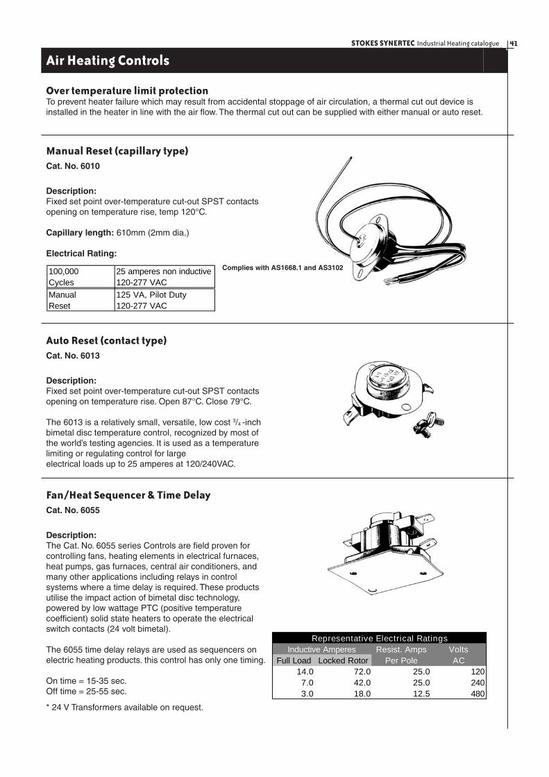
41STOKES SYNERTEC Industrial Heating catalogue
Air Heating Controls
Over temperature limit protectionTo prevent heater failure which may result from accidental stoppage of air circulation, a thermal cut out device is installed in the heater in line with the air fl ow. The thermal cut out can be supplied with either manual or auto reset.
Manual Reset (capillary type)Cat. No. 6010
Description:Fixed set point over-temperature cut-out SPST contacts opening on temperature rise, temp 120°C.
Capillary length: 610mm (2mm dia.)
Electrical Rating:
100,000 25 amperes non inductiveCycles 120-277 VACManual 125 VA, Pilot DutyReset 120-277 VAC
Complies with AS1668.1 and AS3102
Auto Reset (contact type)Cat. No. 6013
Description:Fixed set point over-temperature cut-out SPST contacts opening on temperature rise. Open 87°C. Close 79°C.
The 6013 is a relatively small, versatile, low cost 3/4 -inch bimetal disc temperature control, recognized by most of the world’s testing agencies. It is used as a temperature limiting or regulating control for large electrical loads up to 25 amperes at 120/240VAC.
Fan/Heat Sequencer & Time DelayCat. No. 6055
Description:The Cat. No. 6055 series Controls are fi eld proven for controlling fans, heating elements in electrical furnaces, heat pumps, gas furnaces, central air conditioners, and many other applications including relays in control systems where a time delay is required. These products utilise the impact action of bimetal disc technology, powered by low wattage PTC (positive temperature coeffi cient) solid state heaters to operate the electrical switch contacts (24 volt bimetal).
The 6055 time delay relays are used as sequencers on electric heating products. this control has only one timing.
On time = 15-35 sec.Off time = 25-55 sec.
Resist. Amps VoltsFull Load Locked Rotor Per Pole AC
14.0 72.0 25.0 1207.0 42.0 25.0 2403.0 18.0 12.5 480
Inductive AmperesRepresentative Electrical Ratings
* 24 V Transformers available on request.
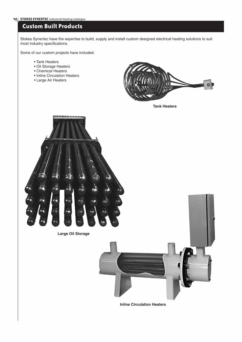
STOKES SYNERTEC Industrial Heating catalogue42
Custom Built Products
Stokes Synertec have the expertise to build, supply and install custom designed electrical heating solutions to suit most industry specifi cations.
Some of our custom projects have included:
• Tank Heaters • Oil Storage Heaters • Chemical Heaters • Inline Circulation Heaters • Large Air Heaters
Large Oil Storage
Inline Circulation Heaters
Tank Heaters
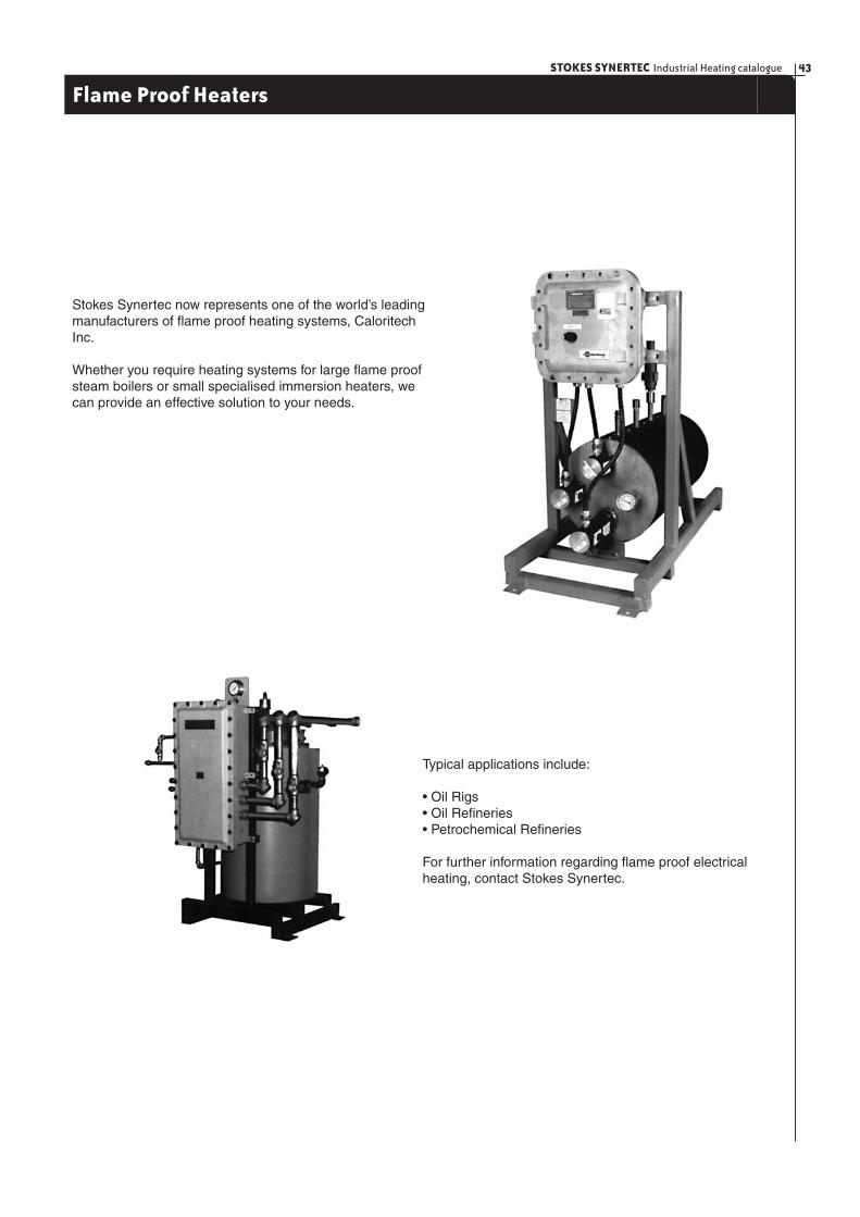
43STOKES SYNERTEC Industrial Heating catalogue
Flame Proof Heaters
Stokes Synertec now represents one of the world’s leading manufacturers of fl ame proof heating systems, Caloritech Inc.
Whether you require heating systems for large fl ame proof steam boilers or small specialised immersion heaters, we can provide an effective solution to your needs.
Typical applications include:
• Oil Rigs• Oil Refi neries• Petrochemical Refi neries
For further information regarding fl ame proof electrical heating, contact Stokes Synertec.

STOKES SYNERTEC Industrial Heating catalogue44
Technical Section (specifi c heats and constants)Heat of Weight
Specific Fusion in LB/Heat BTU/LB (°C) (° F) Cu.Ft.
Aluminium 0.23 138 657 1216 160Antimony 0.052 25 630 1166 423Asphalt 0.4 40 125+ 250+ 65Beeswax - 75 68 144 60Bismuth 0.031 23 270 520 610Brass 0.1 - 938+ 1700+ 525Brickwork and Masonry 0.22 - - - 140Carbon 0.204 - - - -Copper 0.1 75 1083 1981 550Glass 0.2 - 1204+ 2200+ 165Graphite 0.2 - - - 130Iron, Cast 0.13 - 1260+ 2300+ 450Iron,m Wrought 0.12 - 1538+ 2800+ 480Lead, Solid 0.031 10 924 621 710Lead, Melted 0.04 - - - -Nickel 0.11 - 1450 2642 550Paper 0.45 - - - 58Paraffin 0.7 63 50 133 56Pitch, hard - - 150+ 300+ 83Rubber 0.4 - - - 95+Silver 0.057 38 960 1761 655Solder (50% lead - 50% tin) 0.04 17 210 415 580Steel 0.12 - 1390 2550+ 490Sugar 0.3 - 160 320 105Sulphur 0.203 17 221 230 125Tallow - - 32+ 90+ 60Tin, solid 0.056 25 232 450 455Tin, melted 0.064 - - - -Type metal (85% lead - 15% antimony) 0.04 - 260 500 670Wood .450+ - - - 34-pineWood .450+ - - - 50-oakZinc 0.095 51 420 787 445
SubstanceMelting Point
Soli
ds
Specific Approx. WeightProduct Heat in LB. Per Cu. Ft.
at S.T.P.Acetylene 0.35 0.073Air 0.237 0.08Alcohol 0.453 -Amonia 0.52 0.048Argon 0.124 0.1037Carbon Dioxide 0.203 0.123Carbon Monoxide 0.243 0.078Chlorine 0.125 0.2Ethylene 0.4 0.0728Helium 1.25 0.0104Hydrochioric Acid 0.195 0.102Hydrogen .3.41 0.0056Methane 0.6 0.0447Methyl Chloride 0.24 0.1309Nitrig Oxide 0.231 0.0779Nitrogen 0.245 0.078Oxygen 0.218 0.09Sulphur Dioxide 0.155 0.179
Average Heat ofSpecific Vaporisation per Cubic per Imp.
Heat BTU per LB. (°C) (° F) Ft. Gal.Ethylene Glycol 0.602 - 195 387 70.5 11.2Fish Oil - - - - 53 9.3Fuel Oil -Bunker C 0.5 145-150 - - 61 9.6Gasolene 0.675 137 86-90 158-194 48.6 7.7Glue 1/8 Conc. 0.895 - - - 69 11Glycerine 0.58 - 290 554 79 12.7Kerosene 0.47 108 - - 51.5 8.24Mercury 0.0333 117 357 675 845 135.56Milk 1.0(app.) - - - 64.5 10.3Molasses 0.6 - - - 87.4 14Oil- Cottonseed 0.47 - - - 60 9.3Oil - Machine 0.4 - - - 58 9.31Oil- Olive 0.471 - 300+ 570+ 58 9.3Paraffin - Melted 0.71 - 400+ 750+ 56 8.99Petroleum 0.51 - - - 56 8.99Sulphur - Melted 0.234 652 315 601 - -Turpentine 0.41 133 160 319 54 8.66Water 1 965 100 212 62.5 10.01
MaterialBoiling Point Weight in LB.
Gas
es &
Vap
ours
Liq
uid
s
+
+
+
+
+
+
+ +
+
+
+
+
+
+
+
+
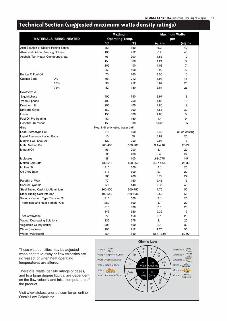
45STOKES SYNERTEC Industrial Heating catalogue
Technical Section (suggested maximum watts density ratings)
MATERIALS BEING HEATED°C (°F) sq. cm (sq.in)
Acid Solution or Electro-Plating Tanks 82 180 6.2 40
Alkali and Oakite Cleaning Solution 100 212 6.2 40
Asphalt, Tar, Heavy Compounds, etc. 95 200 1.55 10
150 300 1.24 8
205 400 1.08 7
260 500 0.93 6
Bunker C Fuel Oil 70 160 1.55 10
Casutic Soda 2% 98 212 6.97 45
10% 98 212 3.87 25
75% 82 180 3.87 25
Dowtherm A -
Liquid phase 400 750 2.97 18
Vapour phase 400 750 1.86 12
Dowtherm E 205 400 1.86 12
Ethylene Glycol 150 300 4.65 30
Freon 150 300 4.65 3
Fuel Oil Pre-heating 82 180 1.4 9
Gasoline, Kerosene 150 300 0.543 3.5
Glue
Lead-Stereotype Pot 315 600 5.42 35 on casting
Liquid Ammonia Plating Baths 10 50 3.87 25
Machine Oil. SAE-30 120 250 2.97 18
Metal Melting Pot 260-480 500-900 3.1-4.18 20-27
Mineral Oil 95 200 3.1 20
205 400 2.48 160
Molasses 38 100 .62-.775 4-5
Molten Salt Bath 430-510 800-950 3.87-4.65 25-30
Molten Tin 315 600 3.1 20
Oil Draw Bath 315 600 3.1 20
205 400 3.72 24
Paraffin or Wax 77 150 2.48 16
Sodium Cyanide 59 140 6.2 40
Steel Tubing Cast into Aluminium 260-400 500-750 7.75 50
Steel Tubing Cast into Iron 400-540 750-1000 8.52 55
Socony Vacuum Type Transfer Oil 315 600 3.1 20
Therminols and Heat Transfer Oils 260 500 3.1 20
315 600 3.1 20
345 650 2.32 15
Trichlorethylene 77 150 3.1 20
Vapour Degreasing Solutions 135 275 3.1 20
Vegetable Oil (fry kettle) 205 400 3.1 30
Water (process) 100 212 7.75 50
Water (washroom) 59 140 12.4-13.95 80-90
Heat indirectly using water bath
MaximumOperating Temp.
Maximum Wattsper
These watt densities may be adjusted when heat take-away or fl ow velocities are increased, or when heat operating temperatures are altered.
Therefore; watts, density ratings of gases, and to a large degree liquids, are dependent on the fl ow velocity and initial temperature of the product.
Visit www.stokessynertec.com for an online Ohm’s Law Calculator.
WWatts
AAmperes
VVolts
OOhms
ER W
E
EI
EW
WR
WR
2
ER
2
W
IIR
EI
WI
2
I R2
Watts =
Watts = Amperes2 x Ohms
Watts = Volts x Amperes
Volts = √Watts x Ohms
Volts =
Volts = Amperes x Ohms
WattsAmperes
Volts2
OhmsAmperes =
Amperes =
Amperes =
Ohms =
Ohms =
Ohms =
Volts2
Watts
VoltsOhmsWattsVolts
WattsOhms
VoltsAmperes
WattsAmperes2
Ohm’s Law
√
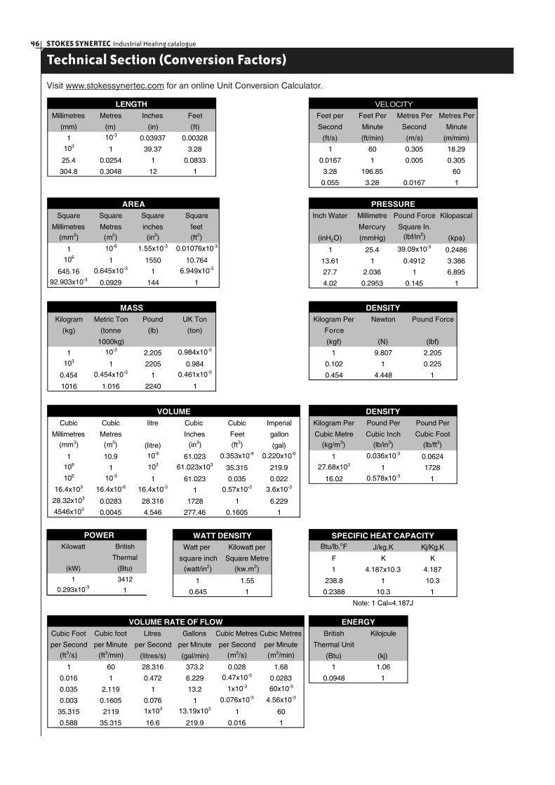
STOKES SYNERTEC Industrial Heating catalogue46
Technical Section (Conversion Factors)
Visit www.stokessynertec.com for an online Unit Conversion Calculator.
Feet per Feet Per Metres Per Metres Per
Second Minute Second Minute
(ft/s) (ft/min) (m/s) (m/mim)
1 60 0.305 18.29
0.0167 1 0.005 0.305
3.28 196.85 60
0.055 3.28 0.0167 1
VELOCITYMillimetres Metres Inches Feet
(mm) (m) (in) (ft)
1 10-3 0.03937 0.00328
103 1 39.37 3.28
25.4 0.0254 1 0.0833
304.8 0.3048 12 1
LENGTH
Square Square Square Square
Millimetres Metres inches feet
(mm2) (m2) (in2) (ft2)
1 10-6 1.55x10⁻³ 0.01076x10⁻³
106 1 1550 10.764
645.16 0.645x10⁻³ 1 6.949x10⁻³
92.903x10⁻³ 0.0929 144 1
AREAInch Water Millimetre Pound Force Kilopascal
Mercury Square In.
(inH2O) (mmHg) (lbf/in2) (kpa)
1 25.4 39.09x10⁻³ 0.2486
13.61 1 0.4912 3.386
27.7 2.036 1 6.895
4.02 0.2953 0.145 1
PRESSURE
Kilogram Metric Ton Pound UK Ton
(kg) (tonne (lb) (ton)
1000kg)
1 10-3 2.205 0.984x10⁻³
103 1 2205 0.984
0.454 0.454x10⁻³ 1 0.461x10⁻³
1016 1.016 2240 1
MASSKilogram Per Newton Pound Force
Force
(kgf) (N) (lbf)
1 9.807 2.205
0.102 1 0.225
0.454 4.448 1
DENSITY
Cubic Cubic litre Cubic Cubic Imperial
Millimetres Metres Inches Feet gallon
(mm3) (m3) (litre) (in3) (ft3) (gal)
1 10.9 10-6 61.023 0.353x10⁻⁹ 0.220x10⁻⁶
109 1 103 61.023x10³ 35.315 219.9
106 10-3 1 61.023 0.035 0.022
16.4x10³ 16.4x10⁻⁶ 16.4x10⁻³ 1 0.57x10⁻³ 3.6x10⁻³
28.32x10³ 0.0283 28.316 1728 1 6.229
4546x103 0.0045 4.546 277.46 0.1605 1
VOLUMEKilogram Per Pound Per Pound Per
Cubic Metre Cubic Inch Cubic Foot
(kg/m3) (lb/in3) (lb/ft3)
1 0.036x10⁻³ 0.0624
27.68x10³ 1 1728
16.02 0.578x10⁻³ 1
DENSITY
Kilowatt British
Thermal
(kW) (Btu)
1 3412
0.293x10⁻³ 1
POWERWatt per Kilowatt per
square inch Square Metre
(watt/in2) (kw.m2)
1 1.55
0.645 1
WATT DENSITYBtu/lb.oF J/kg.K Kj/Kg.K
F K K
1 4.187x10.3 4.187
238.8 1 10.3
0.2388 10.3 1
SPECIFIC HEAT CAPACITY
Note: 1 Cal=4.187J
Cubic Foot Cubic foot Litres Gallons Cubic Metres Cubic Metres
per Second per Minute per Second per Minute per Second per Minute
(ft3/s) (ft3/min) (litres/s) (gal/min) (m3/s) (m3/min)
1 60 28.316 373.2 0.028 1.68
0.016 1 0.472 6.229 0.47x10⁻³ 0.0283
0.035 2.119 1 13.2 1x10⁻³ 60x10-3
0.003 0.1605 0.076 1 0.076x10⁻³ 4.56x10⁻³
35.315 2119 1x10³ 13.19x10³ 1 60
0.588 35.315 16.6 219.9 0.016 1
VOLUME RATE OF FLOWBritish Kilojoule
Thermal Unit
(Btu) (kj)
1 1.06
0.0948 1
ENERGY
GUARANTEEStokes Synertec guarantee electric heating elements manufactured by it to be free from defects in workmanship and materials. Its obligations pursuant to this guarantee are limited to the repair or replacement of any such element which proves defective within the guarantee period, or at Stokes Synertec’s option refund of purchase price. The repair, replacement or refund should be effected upon the defective element being returned freight pre-paid to the Registered Office of Stokes Synertec or to the offices of its accredited Electrical Agents.
Stokes Synertec shall not be responsible for the cost of removing any defective element or reinstalling the repaired or replacement element.
(Where Stokes Synertec supplies goods not of Stokes Synertec’s manufacture the customer shall only be entitled to any such benefits as Stokes may receive under any guarantee given to it in respect thereof.)
GUARANTEE PERIODTwelve (12) months from the date of sale by Stokes Synertec or twenty-four (24) months from the date of manufacture by Stokes, whichever period shall expire first.
CONDITIONSThis guarantee shall not apply-
(a) If notice of the defect has not been given to Stokes Synertec within the guarantee period.
(b) To consequential damage arising out of the alleged failure of the elements supplied.
(c) If the heating element has been- (i) subject to misuse, abuse, negligence or accident;
(ii) subjected to conditions giving rise to sheath corrosion;
(iii) installed, maintained or operated otherwise than in the manner for which it has been designed.
(iv) operated on an electrical supply, the voltage of which varies more than 10% from the rated voltage applicable to the element.
(v) used for any duty or subjected to any abnormal operating condition varying from that for which it was supplied by Stokes Synertec.
Orders will only be accepted and all sales shall proceed subject to Stokes Synertec’s general condition of sale, copies of which are available on request.
StokesSynertec

Innovation by design