
Industrial Heat Tracing · Guide. nVent offers complete integrated service from original design, to...
60
Installation and maintenance manual for mineral insulated cable systems applied to pipes and vessels Industrial Heat Tracing
Transcript of Industrial Heat Tracing · Guide. nVent offers complete integrated service from original design, to...

Installation and maintenance manual for mineral insulated cable systems applied to pipes and vessels
Industrial Heat Tracing
ii | nVent.com
Important Safeguards and Warnings WARNING: FIRE AND SHOCK HAZARD.
nVent RAYCHEM heat-tracing systems must be installed correctly to ensure proper operation and to prevent shock and fire. Read these important warnings and carefully follow all the installation instructions.
• To minimize the danger of fire from sustained electrical arcing if the heating cable is damaged or improperly installed, and to comply with nVent requirements, agency certifications, and national electrical codes, ground-fault equipment protection must be used on each heating cable branch circuit. Arcing may not be stopped by conventional circuit breakers.
• Approvals and performance of the heat-tracing systems are based on the use of approved components and accessories.
• Cable terminations must be kept dry before, during, and after installation.
• Damaged heating cable can cause electrical arcing or fire. Use only RAYCHEM approved pipe straps or tie wire to secure the cable to the pipe.
• Damaged heating cable or terminations must be repaired or replaced. Contact factory for assistance.
• Use only fire resistant insulation which is compatible with the application and the maximum exposure temperature of the system to be traced.
• To prevent fire or explosion in hazardous locations, verify that the maximum sheath temperature of the heating cable is below the autoignition temperature of the gases in the area. For further information, see the design documentation.
• Heating cables are capable of reaching high temperatures during operation and can cause burns when touched. Avoid contact when cables are powered. Insulate the pipe before energizing the cable. Use only properly trained personnel.
• Material Safety Data Sheets (MSDSs) are available on our website: nVent.com
nVent.com | iii
Table of Contents
1 General Information 1
1.1 Use of the Manual 11.2 Safety Guidelines 21.3 Typical System 21.4 Electrical Codes 31.5 Warranty and Approvals 31.6 Heating Cable Construction 41.7 Heating Cable Identification 61.8 Heating Cable Temperature Information 71.9 General Installation Guidelines 71.10 Heating Cable Storage 9
2 Pre-Installation Checks 10
2.1 Check Materials Received 102.2 Check Piping to be Traced 102.3 Check Tools 10
3 Heating Cable Installation 11
3.1 Heating Cable Handling 113.2 Heating Cable Installation on Pipes 163.3 Temperature Sensor Installation for Pipes 233.4 Heating Cable Installation on Tanks and Vessels 243.5 Temperature Sensor Installation for Vessels 27
4 Component Installation 28
4.1 General Component Information 28
5 Control and Monitoring 30

iv | nVent.com
6 Thermal Insulation and Marking 31
6.1 Pre-Insulation Checks 316.2 Insulation Installation Hints 316.3 Marking 326.4 Post-Insulation Testing 32
7 Power Supply and Electrical Protection 33
7.1 Voltage Rating 337.2 Electrical Loading 337.3 Temperature Controller Wiring 34
8 Commissioning and Preventive Maintenance 35
8.1 Tests 358.2 Preventive Maintenance 37
9 Test Procedures 39
9.1 Visual Inspection 399.2 Insulation Resistance Test – Test 1 399.3 Continuity (Resistance) Test – Test 2 409.4 Insulation Resistance and Continuity Test 41
10 Troubleshooting Guide 44
11 Installation and Inspection Records 48
Heating Cable Installation Record 48Installation Record Required for Class I, Division 1,Hazardous Locations According to IEEE 515 50Heating Cable Commissioning Record 52Maintenance Log Record 54
1
nVent.com | 1
General Information
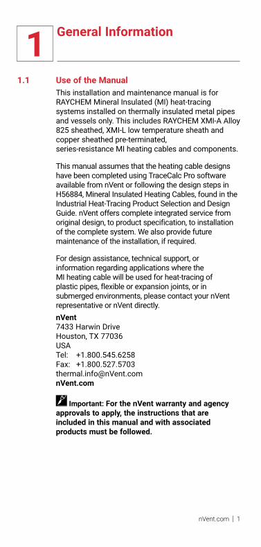
1.1 Use of the ManualThis installation and maintenance manual is for RAYCHEM Mineral Insulated (MI) heat-tracing systems installed on thermally insulated metal pipes and vessels only. This includes RAYCHEM XMI-A Alloy 825 sheathed, XMI-L low temperature sheath and copper sheathed pre-terminated, series-resistance MI heating cables and components.
This manual assumes that the heating cable designs have been completed using TraceCalc Pro software available from nVent or following the design steps in H56884, Mineral Insulated Heating Cables, found in the Industrial Heat-Tracing Product Selection and Design Guide. nVent offers complete integrated service from original design, to product specification, to installation of the complete system. We also provide future maintenance of the installation, if required.
For design assistance, technical support, or information regarding applications where the MI heating cable will be used for heat-tracing of plastic pipes, flexible or expansion joints, or in submerged environments, please contact your nVent representative or nVent directly.nVent7433 Harwin Drive Houston, TX 77036 USA Tel: +1.800.545.6258Fax: [email protected]
Important: For the nVent warranty and agency approvals to apply, the instructions that are included in this manual and with associated products must be followed.
1 General Information
2 | nVent.com
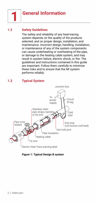
1.2 Safety GuidelinesThe safety and reliability of any heat-tracing system depends on the quality of the products selected, and on proper design, installation, and maintenance. Incorrect design, handling, installation, or maintenance of any of the system components can cause underheating or overheating of the pipe, or damage to the heating cable system, and may result in system failure, electric shock, or fire. The guidelines and instructions contained in this guide are important. Follow them carefully to minimize these risks and to ensure that the MI system performs reliably.
1.3 Typical System
Electric Heat Trace warning label
Pipe to beheated
Stainless steelpipe straps, banding,or tie wire
Tie wire
Heating cablePipe insulation
Drip loop(coil excess cold lead)
Cold lead
Junction box
CircuitID tag
Topower supply
Hot-cold joint
Figure 1: Typical Design B system

1 General Information
nVent.com | 3
1.4 Electrical CodesArticles 427 and 500 of the National Electrical Code and Sections 18 and 62 of the Canadian Electrical Code, Part 1, in particular, govern the installation of electrical heat-tracing systems in hazardous and nonhazardous locations. Installation of heat-tracing systems must comply with all national and local codes. In particular, ground-fault equipment protection is required for all electric heat-tracing installations to prevent arcing, fire, and shock if the cable is improperly installed or damaged.
1.5 Warranty and Approvals
Raychem XMI-A Alloy 825 sheath and copper sheath MI heating cables are approved for use in nonhazardous locations and Class I, Division 1 & 2 Groups A, B, C, D, Class II, Division 1 & 2, Groups E, F, G, Class III hazardous locations and Class I Zone 1 AEx e IIC for US and Ex e IIC for Canada.
Raychem XMI-L low temperature sheath heating cables are approved for use in Class I, Division 2 Groups A, B, C, D, Class II, Division 2, Groups E, F, G Class III hazardous locations and Class I Zone 1 AEx e IIC for US and Ex e IIC for Canada. Refer to specific product data sheets for details.
nVent’s limited standard warranty applies to all products. You can access the complete warranty on nVent.com. To qualify for an extended 10-year warranty, register online within 30 days of installation at nVent.com

1 General Information
4 | nVent.com
1.6 Heating Cable ConstructionThe heating cables are available as factory-terminated units in the configurations shown in Table 1.
TABlE 1: MI HEATING CABlE CONFIGURATION
MI cable design
Number of conductors Configuration
XMI-A Heating CablesA Single conductor
(XMI-A61 series)Heated length Cold lead length
B Single conductor (XMI-A61 series)
Heatedlength
Cold leadlength
Cold leadlength
D Dual conductor (XMI-A32 and XMI-A62 series)
Heated length Cold lead length
E Dual conductor (XMI-A32 and XMI-A62 series)
Heated length
Cold leadlength
Cold leadlength
XMI-l Heating CablesD Dual conductor
(XMI-L32 and XMI-L62 series)
Heated length Cold lead length
E Dual conductor (XMI-L32 and XMI-L62 series)
Heatedlength
Cold leadlength
Cold leadlength

1 General Information
nVent.com | 5
A sectional view of a Design D XMI-A Alloy 825 sheath MI heating cable is shown in Figure 2. All of the cables include both a heating section and a non-heating cold lead section. These sections are joined in the hot-cold joint where the heating element is spliced into larger bus wires. A final transition at the end of the cold lead section provides an environmental seal and tails for the electrical connection. At the opposite end of the cable, the conductors of Design D cables are joined and hermetically sealed within an end cap. XMI-L low temperature sheath cables have an additional corrugated sheath over the heated section as shown in Figures 3 and 4.
Pot
Tails(standard length
12 in (30 cm)
Bus wires Glandconnector
Hot-coldjoint
Cold leadHeated length(length as ordered)
Endcap
Heating element
Figure 2: Sectional view of Design D XMI-A MI cable
Heatingcable
Hot-cold joint Glandconnector
End cap
Corrugated sheath
Pot
Conduit plug
Heated length(length as ordered)
Cold lead
Figure 3: Sectional view of Design D XMI-l MI cable
Hot-coldjoint
Heatingcable
Hot-cold jointGlandconnector
Corrugated sheath
Cold lead Cold leadHeated length
(length as ordered)Pot
Figure 4: Sectional view of Design E XMI-l MI cable

1 General Information
6 | nVent.com
1.7 Heating Cable IdentificationEach MI heating cable is supplied with an identification tag on which the heating cable catalog number is permanently printed. In addition to its identification purposes, the catalog number provides information regarding the heating cable length, power output, and operating voltage. Also printed on the tag are the designer’s circuit identification number, serial number and the maximum temperature the cable sheath may attain along with other design information.If the cable has been designed for a hazardous location, the area classification is printed in the ‘Haz.Locations’ section of the tag.
NVENT THERMAL CANADA LTD.
CATALOGUE NO:NO. DE CATALOGUE:
DESIGN / CABLE REF. / LENGTH / WATTS / VOLTS / C.L. LENGTH / C.L. CODE /JOINT / GLANDDESSIN / REF.DU CABLE / LONGUEUR / WATTS / VOLTS / C.L. LONG / CODE C.L. / JOINT / PRESSE-E-TOUPE
ORDER NO:NO DE COMMANDE:SERIAL NO: NO DE SERIE:OUTPUT POWER:PUISSANCE DE SORTIE:MAX SHEATH TEMP:TEMP DE GAINE MAXIMALE:DESIGN METHOD:METHODE DE DESIGN:CERTIFICATION REF:NO DE CERTIFICATION:
HAZARDOUS LOCATIONS:EMPLACEMENTS DANGEREUX:
FOLLOW INSTALLATION AND OPERATION INSTRUCTIONS FOR SAFE USE IN HARARDOUS AREA! SVP VOUS REFERER AUX INSTRUCTIONS D’INSTALLATION.
CUSTOMER ORDER NO: NO DE COMMANDE DU CLIENT:CIRCUIT ID:ID. DU CIRCUIT:MAINTAIN TEMP OF:TEMP.E MAINTIEN:SHEATH REF TEMP:TEMP DE REF DE LA GAINE:USAGE CODE: CODE D’UTILISATION:T (CODE) / AIT: T (CODE DE) / TAI:
(SEE OTHER SIDE -- VOIR AUVERSO) THIS TAG MUST NOT BE REMOVED - N’ENLEVEZ PAS CETTE ETIQUETTE
727051F1-128341201
@ 130.0 V 120 W @
90ºCSTB
10ºC110ºC
PS
T2A
703862212-HELT-5152-1-01
157944
cCSAus CL I, II, III Div 1 Grp A,B,C,D,E,F,G Ex e IIC Class I Zone 1 Aex e IIC
D/32SA2275/50/120/130/7/LS23A/X/N12
Figure 5: Typical MI identification tag (front)
The heating cable catalog number may be broken out as follows:
Gland size (NPT)
Hot/cold joint type X - use for XMI-A Alloy 825 sheath C - use for XMI-L low temperature sheath Y - use for copper sheath
Cold lead code
Cold lead length (in feet) Metric: 2.1M = 2.1 meters
Heating cable voltage
Heating cable wattage
Heating cable length (in feet) Metric: 10.7M = 10.7 meters
Heating cable reference
Heating cable design configuration (A, B, D, E)
D/32SA2200/35/200/120/7/LS23A/X/N12
Figure 6: MI heating cable catalog number

1 General Information
nVent.com | 7
WARNING: Fire or explosion hazard. Ensure that the information provided in the Haz. locations and Temp. Code [Max. Sheath Temp.] fields comply with the area in which the heating cable will be installed.
1.8 Heating Cable Temperature InformationMI heating cables are available for a variety of applications, with several sheath materials to suit different temperature requirements. The maximum maintain and exposure temperatures for these sheath materials is shown in Table 2.
TABlE 2: MAXIMUM CABlE TEMPERATURE
Product family
Maximum maintain temperature
Maximum continuous exposure temperature
Maximum continuous exposure temperature for hot/cold joints and end cap
XMI-A 1022°F (550°C) 1200°F (650°C) 1022°F (550°C)
XMI-L (Note 1) 752°F (400°C) 1022°F (550°C) 1022°F (550°C)
Copper 300°F (150°C) 392°F (200°C) 300°F (150°C)
LSZH jacketed copper
158°F (70°C) 194°F (90°C) 194°F (90°C)
Note 1: 842°F/450°C if corrosives are present
1.9 General Installation GuidelinesThese guidelines are provided to assist the installer throughout the installation process and should be reviewed before the installation begins.
Avoid damage to the MI heating cable as follows:• Do not repeatedly bend and straighten the cable.• Do not bend within 6 inches (15 cm) of a splice,
the hot-cold joint, or the end cap.• Do not bend the cold lead within 6 in (15 cm) of
the termination pot seal.• Do not alter cable length.• Do not energize before installation is complete.• Do not use screw type adjustable pipe straps/
banding.• Avoid crushing and excessive bending or pulling
of cold leads during installation, testing and commissioning

1 General Information
8 | nVent.com
• Do not install so that cables are crossed, overlapped, or grouped. Grouped cables can cause localized overheating with a risk of fire or cable failure.
• Keep welding torches well clear of cable and protect against slag falling on cables below.
Important: When welding, the ground clamp must be kept as close to the welding area as possible.
• Ensure all pipes, tanks, etc., have been released by the client for tracing prior to heating cable installation.
• Heating cables must be spaced at least 1/2 in (13 mm) from any combustible surface.
• The metal sheath of XMI-A and XMI-L heating cables shall be bonded to the circuit bonding conductor, but shall not be used as the bonding means. Metallic structures or materials used for the support of, or on which the heating cables are installed, must be bonded to ground in accordance with CSA Standard C22.1, Section 10, or the National Electrical Code as applicable.
• In case of multiple tracing or spiraling, space cable(s) at least 1 inch (2.5 cm) apart, if possible (Figure 17).
• Install cable in a manner that permits removal of serviceable equipment such as valves, pumps, filters, and so on, with minimum disruption to the surrounding heating cable.
• Use stainless steel pipe straps, stainless steel banding, or 16 AWG or larger stainless steel tie wire to fasten XMI-A and XMI-L heating cables to pipes. Use stainless steel pipe straps, stainless steel banding, or 16 AWG or larger copper tie wire to fasten copper sheathed heating cables to pipes.
• Avoid bending cable to an inside radius less than 6 times the outside diameter of the cable, when installing on valves, pumps, and other irregularly shaped surfaces. On small flanges and joints where it is impractical to bend the cables tightly, metal foil or metal bridging pieces can be used to fill gaps between the heating cable and the surface to be heated.

1 General Information
nVent.com | 9
• Ensure heating cable sheath material is suitable for the maintain and continuous exposure temperatures shown in Table 2. If the anticipated maximum continuous exposure temperature of the hot-cold joint or end cap of the cable to be installed exceeds the values in Table 2, install as shown in Figure 26.
• Apply thermal insulation as soon as possible after heat-tracing to prevent mechanical damage to the heating cables. Waterproof cladding must be installed immediately after insulation is applied to prevent the insulation from becoming wet.
• Make all connections to supply cables in above grade junction boxes and keep covers on junction boxes when not working on them.
• To maintain the integrity of the epoxy seal termination, avoid the application of excessive heat to the epoxy during installation, commissioning and operation of the heating units
• The minimum installation temperature is –76°F (–60°C).
• Use a temperature controller suitable for the process temperature. nVent supplies a wide range of temperature controllers including the RAYCHEM series electronic monitoring controllers.
Important: DO NOT remove metal tags from cold lead.
Important: Repair or assembly of field-fabricated units shall be done by a person qualified to do so and in accordance with the nVent requirements.
1.10 Heating Cable Storage• Store heating cables in a clean dry location and
protect them from mechanical damage.• Temperature range –40°F to 140°F
(–40°C to 60°C)• Store heating cables in their shipping container
until they are installed.
2 Pre-Installation Checks
10 | nVent.com
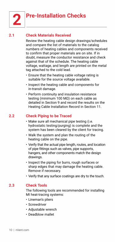
2.1 Check Materials ReceivedReview the heating cable design drawings/schedules and compare the list of materials to the catalog numbers of heating cables and components received to confirm that proper materials are on site. If in doubt, measure the conductor resistance and check against that of the schedule. The heating cable voltage, wattage, and length are printed on the metal tag attached to the cold lead.• Ensure that the heating cable voltage rating is
suitable for the source voltage available.• Inspect the heating cable and components for
in-transit damage.• Perform continuity and insulation resistance
testing (minimum 100 MΩ) on each cable as detailed in Section 9 and record the results on the Heating Cable Installation Record in Section 11.
2.2 Check Piping to be Traced• Make sure all mechanical pipe testing (i.e.
hydrostatic testing/purging) is complete and the system has been cleared by the client for tracing.
• Walk the system and plan the routing of the heating cable on the pipe.
• Verify that the actual pipe length, routes, and location of pipe fittings such as valves, pipe supports, hangers, and other components match the design drawings.
• Inspect the piping for burrs, rough surfaces or sharp edges that may damage the heating cable. Remove if necessary.
• Verify that any surface coatings are dry to the touch.
2.3 Check ToolsThe following tools are recommended for installing MI heat-tracing systems:• Lineman’s pliers• Screwdriver• Adjustable wrench• Deadblow mallet

3 Heating Cable Installation
nVent.com | 11
3.1 Heating Cable Handling• Handle heating cable with care. Take care when
bending the cable around pumps, valves, and flanges.
• Protect cold lead tails from damage by threading a short section of PVC pipe on to the gland connector as shown.
ThreadedPVC end
Gland connectorPVC pipeCold
leadHeatingcable
Figure 7: Protecting cold lead tails
• Avoid damaging heating cables by cutting or crushing.
• Uncoil heating cables along a floor or surface to avoid kinking or twisting. DO NOT pull out into a spiral.
• Handle the hot-cold joint carefully. Support the joint on both sides when moving and positioning the cold lead.
• Do not bend the cold lead using a length of pipe, placed over the tails and pot, as a fulcrum to facilitate the bend. The cold lead and/or pot will be damaged. Bend the cold lead using a bending tool designed to bend cable or conduit.
• Keep cables clean and dry.• To prevent galling of threads when using stainless
glands, a thread lubricant should be applied to the male thread mating with the female backnut.
Heating cable allowances
All parts of a heat traced system which increase the surface area of the normally insulated pipe/ vessel (e.g. valves or flanges) or metallic fins that protrude out of the insulation (e.g. supports), will increase the overall heat loss. These areas of increased heat loss require compensation, either by using higher overall design safety factors or by the addition of extra cable length. The heating cable allowances are specified in design software and documentation.
12 | nVent.com
3 Heating Cable Installation
In such cases sufficient cable should be added in such a way to at least enable removal of instruments, valves etc (“maintenance loop”). For pipes requiring more than one run of heating cable, apply the full allowance for each run of cable on each fitting or support as long as space allows. However, MI heating cables must not touch or overlap and the minimum spacing between the heating cables must be observed. The minimum spacing between cables is 1” (2.5cm). Contact nVent if more than two runs are needed or if cable spacing is less than 1” (2.5 cm). For some applications, it may be physically impossible to install all of the recommended allowance directly on the fitting or support. In this case, install the excess heating cable on the pipe on either side of the fitting or support, or distribute the additional heater length along the entire circuit length if a lower local temperature is acceptable.
This constraint may be difficult for small pipes and/or multiple cable runs. If required, contact nVent for assistance.
For further details on individual allowances please refer to the design documentation or the nVent design software (e.g. TraceCalc Pro reports).
For NPS sizes 2" and smaller (in outdoor applications where wind may be significant) it is recommended that all components are fully insulated as there is a risk of a lower maintain temperature on the components due to heat losses.

3 Heating Cable Installation
nVent.com | 13
Positioning heating cablesInstall cables around the bottom section of pipe, avoiding bottom dead center (Figure 8).For two cable runs, install between 30° and 45° on either side of bottom dead center (Figure 8).
For three cable runs (as in a three phase installation) install bottom cable about 10° to one side of bottom dead center (Figure 8). On a vertical pipe, space cables evenly around circumference of pipe.
Weatherproofjacket (typ)
Insulation(typ)Cable ‘A’
Pipe
One heating cable
Three heating cables
Cable ‘C’
Cable ‘B’Cable ‘A’
Cable ‘A’
Two heating cables
Cable ‘B’
Temperaturesensor
Temperaturesensor
TemperatureSensor
Figure 8: Cable positioning—typical cross section
Care must be taken at joints, flanges, valves or any obstructions on the pipe line to prevent damage to the heating cables during installation.

3 Heating Cable Installation
14 | nVent.com
Attaching cold leadsAttach the hot/cold joint to the pipe or vessel ensuring that it is firmly anchored to the heated surface and check that the hot/cold joint is not damaged during installation.
Important: In some instances it is not permitted to have a hot-cold joint or end cap anchored to the heated surface because of the risk of exceeding the maximum recommended exposure temperature (see Table 2). In such instances, follow the installation detail shown in Figure 26.
Cold leads should always emerge from the thermal insulation in such a way that the resultant hole in the insulation cannot admit water or other contaminants. Coil excess length of cold lead as it exits the insulation (Figure 16) and ensure that cold leads can accommodate any movement of the pipe work.
Bending the cable
6X heating cable O.D.
Heating cable O.D.
Figure 9: Minimum bend radius
3 Heating Cable Installation
nVent.com | 15
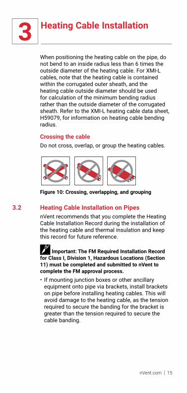
When positioning the heating cable on the pipe, do not bend to an inside radius less than 6 times the outside diameter of the heating cable. For XMI-L cables, note that the heating cable is contained within the corrugated outer sheath, and the heating cable outside diameter should be used for calculation of the minimum bending radius rather than the outside diameter of the corrugated sheath. Refer to the XMI-L heating cable data sheet, H59079, for information on heating cable bending radius.
Crossing the cableDo not cross, overlap, or group the heating cables.
Figure 10: Crossing, overlapping, and grouping
3.2 Heating Cable Installation on PipesnVent recommends that you complete the Heating Cable Installation Record during the installation of the heating cable and thermal insulation and keep this record for future reference.
Important: The FM Required Installation Record for Class I, Division 1, Hazardous locations (Section 11) must be completed and submitted to nVent to complete the FM approval process.• If mounting junction boxes or other ancillary
equipment onto pipe via brackets, install brackets on pipe before installing heating cables. This will avoid damage to the heating cable, as the tension required to secure the banding for the bracket is greater than the tension required to secure the cable banding.

3 Heating Cable Installation
16 | nVent.com
• Where feasible, uncoil the single heating cable and lay it alongside the pipe section to be traced. For shorter Design B single conductor cable which is to be installed in the form of a “hairpin,” it may be advantageous to unroll the heating cable, loop it, and then lay it alongside the pipe section so that both runs of cable can be installed simultaneously.
Endcap
Figure 11: Uncoiling heating cable
• Attach hot-cold joint to end of pipe nearest the power supply point, and other end of heating cable to the other end of the pipe. Support hot-cold joint by attaching cable with pipe straps/banding at a distance of 6 inches (15 cm) on either side of joint. Secure joint itself to pipe with a pipe strap/band as shown in Figure 16.
• Fasten middle of heating cable to the halfway point of pipe leaving equal slack on either side.
Endcap
Figure 12: Attaching hot-cold joint and end cap
• Attach heating cables to pipe with pipe straps/banding, or tie wire, at intervals of 18 inches (45 cm) or less. Tie wire should be snug, but should not cut or indent the sheath. When installing copper sheathed heating cables using tie wire, use only 16 AWG or larger copper tie wire to prevent cutting into the cable sheath.
• Allow extra cable per design specifications and drawings at all pipe fixtures.

3 Heating Cable Installation
nVent.com | 17
Stainless steel pipe strap,banding, or tie wire
Leave large bending radii (typ)
Figure 13: Allowances for valves, flanges, and pipe supports
• Use tie wire to hold cable to irregularly shaped components such as valves or pipe supports.
• In hazardous locations, when attaching heating cable to irregular shaped components such as flanges and valves, use pipe straps on either side of the component to secure the cable to the pipe.
Figure 14: Installing cable on valves and pipe supports
• Allow cable to wave along pipe as per Figure 16 and Figure 17. This allows for expansion and contraction of the heating cable as it heats up and cools down. Use up excess cable by waving along pipe and increasing amount used at each pipe support.
Important: Do not use up excess cable at one location. Distribute equally along pipe.

3 Heating Cable Installation
18 | nVent.com
Hot-cold joint
Tie wire
Figure 15: Completed MI heating cable installation
Important: For hazardous area installations any reapportioning of cable should be verified by those responsible for the system design.
Important: If tensioning tools are used, avoid over-tightening pipe straps, banding, or tie wire used to attach heating cable as this can damage the heating cable. This permits movement of heating cable during its heating cycle, as restricted movement can lead to cable failure due to fatigue.
WARNING: Fire and shock hazard. Do not install damaged cable. Heating cable must be repaired or replaced before installation.
Typical pipe installation detailsThe following illustrations show general installation methods. Actual installation configurations will vary depending on the number of heating cables being installed and the shape of the components being traced.
Stainless steel pipe straps,banding, or tie wire
Drip loop
Coldlead
Hot-coldjoint
Junction box
6"(15 cm)
6"(15 cm)
Insulation 18" max(45 cm)
Figure 16: Pipe strap spacing

3 Heating Cable Installation
nVent.com | 19
Note: Where several runs of cable are required on one pipe, prepunched strapping may aid in the installation and spacing of cables.
18" max(45 cm)
1/2" (13 mm) wide s/s banding(tighten with hand-tensioner only)
Prepunched s/s strapping
Wave cables 1" (2.5 cm) to 2" (5 cm) along pipe
Figure 17: Fastening several runs of cable
Stainless steel pipe straps,banding, or tie wire
For valve sizes 3-1/2" (9 cm) or smaller
For valve sizes larger than 3-1/2" (9 cm)
Pipe Valve body
MI heating cableSee design drawingfor specific heatingcable length needed.
MI heatingcable
Apply stainlesssteel tie wire tohold MI heatingcable in place.
Stainless steel pipe straps,banding, or tie wire
Pipe Valve body
Apply stainlesssteel tie wire tohold MI heatingcable in place.
MI heatingcableMI heating cable
See design drawingfor specific heatingcable length needed.
Figure 18: Valves
3 Heating Cable Installation
20 | nVent.com
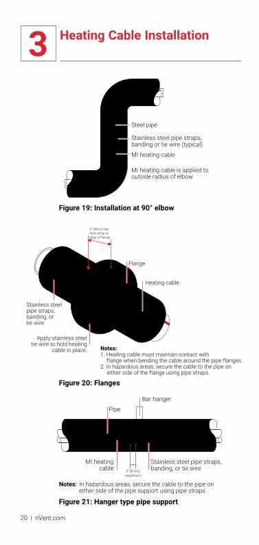
Steel pipe
Stainless steel pipe straps, banding or tie wire (typical)
MI heating cable
MI heating cable is applied tooutside radius of elbow.
Figure 19: Installation at 90° elbow
Flange
3" (8cm) max from strap to edge of flange
Heating cable
Apply stainless steeltie wire to hold heating
cable in place.
Stainless steel pipe straps,banding, or tie wire
Notes:1. Heating cable must maintain contact with flange when bending the cable around the pipe flanges.2. In hazardous areas, secure the cable to the pipe on
either side of the flange using pipe straps.
Figure 20: Flanges
MI heatingcable
Stainless steel pipe straps, banding, or tie wire
PipeBar hanger
3” (8 cm)maximum
Notes: In hazardous areas, secure the cable to the pipe on either side of the pipe support using pipe straps
Figure 21: Hanger type pipe support

3 Heating Cable Installation
nVent.com | 21
Stainless steel pipe straps, banding, or tie wire (typical)
Note: Minimum 1" (2.5 cm) spacing, if possible.
See design drawings for specificheating cable length needed.
MI heating cable Pipe
Figure 22: Shoe and sleeve type support
Stainless steel pipe straps, banding, or tie wire
Insulation
Dummy leg
Notes:1. Minimum 1" (2.5 cm) spacing.2. Check drawings for dummy leg insulation.
Pipeshoe
Heatingcable
Figure 23: Dummy supports

3 Heating Cable Installation
22 | nVent.com
Pumps should have their own heating cable, separate from the connecting pipe.
Stainless steel pipe straps,banding, or tie wire
Pumpbody
MotorStainless steel tie wire isrequired on both sides tohold heating cable in place.
Heatingcable
Junction box (series connect)
Notes: 1. Minimum 1" (2.5 cm) spacing, if possible.2. Cover heating cable with metal foil or equal before
applying insulation to ensure the cable does not become trapped in the insulation.
Figure 24: Pumps
Insulatingspacers
6" (15 cm)
6" (15 cm)
8' max (2.5 m)
2' max (60 cm)
2' max (60 cm)Insulatingspacers
Notch insulation spacers to clear heating cable(approx 3/8" (9.5 mm) x 3/8" (9.5 mm))
Section ‘A’ – ‘A’
‘A’ ‘A’
Notes: 1. When using oversize insulation to allow space for heat tracing, use insulating spacers at intervals not exceeding 8 ft (2.5 m) to reduce chimney effect between the pipe and insulation.2. Insulating spacers to be same material as oversize insulation.
Figure 25: Risers

3 Heating Cable Installation
nVent.com | 23
Stainless steel pipe straps,banding, or tie wire
Insulation
Heating cable
Detail
Split metal sleeveover hot-cold jointpartially exitinginsulation (see detail)
Hot-cold joint(keep off pipe)
Figure 26: When maximum pipe temperature exceeds cold lead or hot-cold joint and end cap capability
Heating cable
Stainless steelpipe straps,
banding,or tie wire
Pipe
Figure 27: Pressure gauge
3.3 Temperature Sensor Installation for PipesSecure the temperature sensor to the pipe using pipe straps or banding. Position the sensor element parallel to the pipe and in a location where it will not be affected by the heating cable (Figure 28). In all cases it is essential that the temperature sensor

3 Heating Cable Installation
24 | nVent.com
be positioned in accordance with the designer’s instructions.
Important: The temperature sensor must be installed so that it senses the temperature conditions within the heating zone. For example, where flow and static conditions occur within one heating zone, the temperature sensor should be located at a point of no flow and away from the end of the pipe or a component such as a pipe support.
Temperaturesensor
Heating cablehot section
Sensorlead
‘A’
Section ‘A’ – ‘A’
‘A’
Heating cablePipe
Temperaturesensor
Stainless steelpipe straps, or banding
Figure 28: Pipe-mounted temperature sensor
The temperature sensor should be strapped in good thermal contact with the pipe and protected so that insulating materials cannot become trapped between it and the heated surface. Install temperature sensor with care as damage may cause a calibration error.
3.4 Heating Cable Installation on Tanks and VesselsOn vessels, tanks, or large surfaces, the heating cable is worked onto the area to form a heating mat. Prepunched strapping, where allowable, may be spot welded to the surface of the vessel to be heated and the heating cable attached to it. When using prepunched strapping, bend the tabs on the prepunched strapping backwards over the cable as shown in Figure 29. Note that prepunched strapping will not accommodate XMI-L cables due to the larger diameter of the outer corrugated sheath. In this case, wire mesh and tie wire may be used.For irregular shaped vessels, or when installing

3 Heating Cable Installation
nVent.com | 25
XMI-L heating cables, the surface can be covered with a wire mesh and the heating cable fastened to the wire mesh using tie wire. Alternatively, the heating cable may be fastened to the wire mesh and the mesh applied to the vessel.
Consult design schedule for limits, proportions and spacing when marking out the surface area and ensure that the prepunched strapping or wire mesh is suitably located. This can be best achieved by marking out the cable run for spacing and extremities of the cable loops (Figure 29).
Use the following formula to determine cable spacing:
Cable spacing (in) = Area to be heated (ft2) x 12 Length of heating cables (ft)
Or if metric:
Cable spacing (mm) = Area to be heated (m2) x 1000 Length of heating cables (m)
Locate termination end of heating cable and attach to vessel, usually near electrical supply point. Trace over space marking and secure to vessel using previously attached prepunched strapping (Figure 29). Pay attention to minimum bending radius and heating cable spacing when forming loops.

3 Heating Cable Installation
26 | nVent.com
Looppositions
Radius of loops
Spacemarkings
Prepunchedstrapping
Heating cableTab – bend backwards over cable so smooth edge holds cable (sharp edge up)
Prepunchedstrapping
Figure 29: Cable layout using prepunched strapping
Install stainless steel banding over heating cable and strapping as shown in Figure 30. This prevents cable runs from becoming loose if they slip out from the “clip” on the strapping.
3 Heating Cable Installation
nVent.com | 27
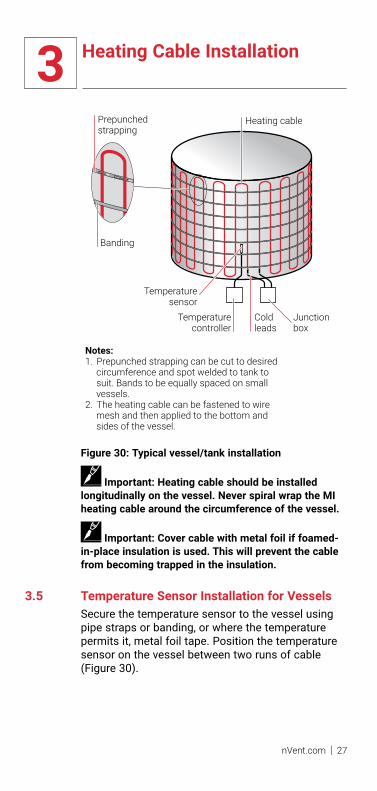
Coldleads
Junctionbox
Temperaturecontroller
Heating cable
Temperaturesensor
Banding
Prepunchedstrapping
Notes: 1. Prepunched strapping can be cut to desired
circumference and spot welded to tank to suit. Bands to be equally spaced on small vessels.
2. The heating cable can be fastened to wire mesh and then applied to the bottom and sides of the vessel.
Figure 30: Typical vessel/tank installation
Important: Heating cable should be installed longitudinally on the vessel. Never spiral wrap the MI heating cable around the circumference of the vessel.
Important: Cover cable with metal foil if foamed-in-place insulation is used. This will prevent the cable from becoming trapped in the insulation.
3.5 Temperature Sensor Installation for VesselsSecure the temperature sensor to the vessel using pipe straps or banding, or where the temperature permits it, metal foil tape. Position the temperature sensor on the vessel between two runs of cable (Figure 30).

4 Component Installation
28 | nVent.com
4.1 General Component InformationRAYCHEM heating cables must be terminated in a junction box suitable for the area classification.Select appropriate components from nVent literature number H56884, Mineral Insulated Heating Cables, found in the Industrial Heat-Tracing Product Selection and Design Guide, or by using TraceCalc Pro software.
Component installation tips• Ensure that the heating cable cold lead angles
downward as it exits the insulation to prevent water ingress (Figure 16).
• Plan the location of the power connection junction box so that the excess cold lead can be coiled before entering the box, then mount the box firmly to a beam, stanchion, or pipe using appropriate mounting brackets. For series connected heating cables, junction boxes may be installed in a similar manner.
• Cable or conduit leading to junction boxes, temperature controllers, and transformers must be installed so that water does not enter the enclosure.
• Side entries are preferred to avoid condensation in bottom of junction box.
• Do not bend the cold lead within 6 in (15 cm) of the termination pot seal.
• Perform visual inspection of glands for scratches or damage, including threads
• Ensure surface of cable where gland will seal to sheath is clean
• If gland is contaminated: disassemble, clean, and visually inspect contaminated parts
• In CID1 hazardous locations glands must have a minimum of 5 threads engaged.

4 Component Installation
nVent.com | 29
Gland connector
Pot
Glandconnector
When possible extend pot inside junction box
Figure 31: Junction box connection
• If necessary, remove the hole plug where the cold lead will enter the junction box. Screw a reducer into the junction box conduit hub if required, then insert the tails and screw the gland connector tight. Tighten the compression nut.
Important: Make sure that the tails do not become trapped between the pot and gland connector or reducer bushing, if used.
Important: The compression nut must be tightened to the torque setting indicated on the tag attached to the gland connector. This ensures that the cable sheath is properly grounded and prevents moisture from entering the junction box.
• Perform visual inspection of gland after tightening back nut and check for cracks, deformation / out-of-round.
• The torque tag on glands should not be removed (ensuring information available for future maintenance)
• Connect the cold lead tails and distribution power wires to the terminal block.
• Position the terminal block and wiring in the junction box and install the box lid. Make sure lid is watertight. Check to make sure that hole plugs are firmly tightened into any unused conduit hubs.
FM note:
When installing FM certified units, the pot must be fully recessed inside the gland body.

5 Control and Monitoring
30 | nVent.com
RAYCHEM control and monitoring products are designed for use with Mineral Insulated heat-tracing systems. Thermostats, controllers and control and monitoring systems are available. Compare features of these products in the table below. For additional information on each product, refer to the Industrial Product Selection and Design Guide or contact your nVent representative.
Refer to the installation instructions supplied with control and monitoring products. Control and Monitoring systems should be installed by a certified electrician.
TABlE 3: RAYCHEM CONTROl AND MONITORING PRODUCTS
Thermostats Controllers
AMC-1BAMC-2B-2E507S-lSE507S-2lS-2Raystat-EX03-A
RAYCHEM Series
910 920 NGC-30 NGC-40
ControlAmbient sensing • • • •line-sensing • • • •PASC • • • •
MonitoringAmbient temperature • • • • Pipe temperature • • • •Ground fault • • • •Current • • • •
locationlocal • • • •Remote • • • •Hazardous E507S • • • •
Communicationslocal display • • •Remote display • •Network to DCS • • • •
Indicates an optional component

6 Thermal Insulation and Marking
nVent.com | 31
6.1 Pre-Insulation ChecksVisually inspect the heating cable and components for possible damage or incorrect installation. Damaged cable must be repaired or replaced.
Perform continuity and insulation resistance tests on each cable following the procedure in Section 9. Confirm the results meet the minimum requirement stated in Test 1 and Test 2 and record them on the Heating Cable Installation Record in Section 11.
6.2 Insulation Installation Hints• Make sure all of the piping is insulated according
to the design specification, including valves, flanges, pipe supports, and pumps.
• Ensure thermal insulation is suitable for the temperatures involved and for the location of the pipe (i.e. outdoors or below grade).
Important: Some types of insulation may be damaged by the high operating temperature reached by some MI cables.• Ensure that heating cable does not become
trapped in the joint between the two half shells of insulation. In some cases, it may be necessary to cover the heating cable with metal foil to avoid this problem.
• Insulation must be properly installed and kept dry.• Check insulation type and thickness against the
design specification.• To minimize potential heating cable damage,
insulate as soon as possible after tracing.• Check that pipe fittings, wall penetrations, and
other irregular areas, have been completely insulated.
• When installing waterproof cladding, be sure drills, screws and sharp edges do not damage the heating cable. The cladding must be installed immediately after insulation is applied to prevent the insulation from becoming wet.

6 Thermal Insulation and Marking
32 | nVent.com
• To weatherproof the insulation, seal around all fixtures that extend through the cladding. Check around valve stems, support brackets, and thermostat capillaries and sensor leads.
• To minimize “chimney effect” on vertical lengths of piping when using oversized insulation, install baffles between the thermal insulation and the pipe at maximum 8-foot (2.5 m) intervals (Figure 25).
• To prevent localized overheating, do not allow thermal insulation or other material to become lodged between the cable and the pipe. If urethane foam insulation is applied over heating cable, special care must be taken to ensure that the urethane does not get between the MI heating cable and the pipe. This can be accomplished by banding the cable to the pipe, and applying a strip of metal foil longitudinally to the pipe over the cable.
WARNING: Use only fire-resistant insulation such as fiberglass, mineral wool or calcium silicate.
6.3 MarkingInstall “Electrically Traced,” or similar, warning labels along piping at 10-foot (3 m) intervals on alternate sides, and on equipment requiring periodic maintenance, such as valves, pumps, filters, and so on, to indicate presence of electric heating cables.
6.4 Post-Insulation TestingAfter the insulation is complete, perform a continuity and insulation resistance test on each circuit to confirm that the cable has not been damaged (refer to Section 9).

7 Power Supply and Electrical Protection
nVent.com | 33
7.1 Voltage RatingVerify that the source voltage corresponds to the heating cable voltage rating printed on the cable tag. For circuits where the heating cables are series connected, the sum of the voltages shown on the cable tags should equal the source voltage.
7.2 Electrical loadingSize the over-current protective devices according to the design specification. If devices other than those identified are used, refer to the current rating (amps) on the heating cable tag to determine the electrical load.
Ground-fault protectionUse circuit breakers with 30-mA ground-fault protection on all heating cable circuits.nVent, the U.S. National Electrical Code, and the Canadian Electrical Code require both ground-fault protection of equipment and a grounded metallic covering on all heating cables. All RAYCHEM products meet the metallic covering requirement. RAYCHEM series electronic monitoring controllers incorporate adjustable ground-fault protection, eliminating the need for separate ground-fault breakers.
WARNING: To minimize the danger of fire from sustained electrical arcing if the heating cable is damaged or improperly installed, and to comply with nVent requirements, agency certifications, and national electrical codes, ground-fault equipment protection must be used on each heating cable branch circuit. Arcing may not be stopped by conventional circuit breakers. (See code for exceptions.)
WARNING: Disconnect all power before making connections to the heating cable.
Important: Contact nVent for installation details for low voltage applications where a step-down transformer is used to provide power to the heating cable.

7 Power Supply and Electrical Protection
34 | nVent.com
7.3 Temperature Controller WiringWiring diagrams for typical temperature controllers are supplied with the controller. A contactor may be used to switch loads greater than the maximum current or voltage rating of the controller. Contact nVent for details.
Contactor current ratings: Always ensure that current ratings of the switch contacts are not exceeded. Inrush current may be higher than normal operating current, particularly with copper conductor heating cables.

8 Commissioning and Preventive Maintenance
nVent.com | 35
nVent requires a series of tests be performed on the heat-tracing system upon commissioning. These tests are also recommended at regular intervals for preventive maintenance. Record and maintain results for the life of the system, utilizing the Heating Cable Commissioning Record (refer to Section 11).
8.1 TestsA brief description of each test is found below. Detailed test procedures are found in Section 9.
Visual inspectionVisually inspect the pipe, insulation, and connections to the heating cable for physical damage. Check that no moisture is present in junction boxes, electrical connections are tight and grounded, insulation is dry and sealed, and control and monitoring systems are operational and properly set. Damaged heating cable must be repaired or replaced.
Continuity and insulation resistanceContinuity and insulation resistance testing are recommended at four stages during the installation process, and as part of regular system inspection, and after any maintenance or repair work. Continuity testing checks the integrity of the resistive heating element inside the heating cable. IR testing checks the integrity of the electrical insulating barrier between the resistive heating element and the cable sheath. IR testing is analogous to pressure testing a pipe and detects damage to the heating cable sheath or terminations. IR testing can also be used to isolate the damage to a single run of heating cable. Fault location can be used to further locate damage.
Power check
Line-sensing controlled systemsCheck circuit breaker sizing and the supply voltage to make sure that it is suitable for the heating cable voltage rating and amperage printed on the heating cable identification tag.
8 Commissioning and Preventive Maintenance
36 | nVent.com
• Turn on the main circuit breaker.• Turn on the branch circuit breakers.• Set the temperature controller or thermostat to
the desired control temperature, or to a setting high enough to turn the circuit on if the pipe temperature is above the control temperature.
• Allow the system to reach the control point and the current to stabilize. This may take several hours for some circuits.
• Measure the voltage and pipe temperature for each circuit and record the values in the Heating Cable Commissioning Record (refer to Section 11). This information is needed for future maintenance and troubleshooting.
• Measure the circuit current using a clamp-on or panel ammeter. The measured value should be approximately the number shown under “Amps” on the heating cable identification tag. Variations of 10% to 20% are possible due to deviations in measurement equipment, supply voltage, and cable resistance. Record the values in the Heating Cable Commissioning Record in Section 11.
• When the system is completely checked out, reset the temperature controller to the proper temperature.
The heating cable power (wattage) can be calculated by multiplying the measured voltage by the measured current using the following formula:
Power (W) = Volts (Vac) x Current (A)
The calculated wattage can be compared to the wattage indicated on the heating cable tag at the temperature of operation. This gives a good indication of heating cable performance.
Control and monitoring systemsRefer to the installation instructions supplied with the product for commissioning tests and records.
Important: The current and resistance of some MI heating cables can vary with temperature. Higher maintain temperatures may result in higher cable resistances and decreased current.

8 Commissioning and Preventive Maintenance
nVent.com | 37
Ground-fault testTest all ground-fault breakers per manufacturer’s instructions.
8.2 Preventive MaintenanceRecommended maintenance for nVent heat-tracing systems consists of performing the commissioning tests on a regular basis, preferably at least once a year, unless a RAYCHEM series electronic monitoring controller is used. These controllers automatically exercise and monitor the heating cable circuit for faults. Systems that use electro-mechanical thermostats for control should be checked before each winter.If the heat-tracing system is found to be defective, refer to Section 10 for troubleshooting assistance. Make the necessary repairs and replace any part of the heat-tracing system if it has been found to be defective.
De-energize all circuits that may be affected by maintenance.
Protect the heating cable from mechanical or thermal damage during maintenance work.
The recommended cable installation methods allow for extra cable at all pipe fixtures (such as valves, pumps, and pressure gauges) so that cable does not have to be cut when performing maintenance work.
Maintenance recordsnVent recommends that the Maintenance Log Record (refer to Section 11) be completed during all inspections and kept for future reference.

8 Commissioning and Preventive Maintenance
38 | nVent.com
RepairsUse only RAYCHEM MI cable and components when replacing any damaged cable. Repairs should be performed only by qualified personnel and to nVent requirements. Replace the thermal insulation to original condition or replace with new insulation, if damaged.
Retest the system after repairs.
WARNING: Damage to cables or components can cause sustained electrical arcing or fire. Do not energize cables that have been damaged. Damaged heating cable or terminations must be repaired or replaced. Damaged cable should be repaired by a qualified person.
WARNING: Heating cables are capable of reaching high temperatures during operation and can cause burns when touched. Avoid contact when cables are powered. Insulate the pipe before energiz-ing the cable. Use only properly trained personnel.

9 Test Procedures
nVent.com | 39
nVent recommends that the Heating Cable Installation Record be completed during testing and kept for future reference.
9.1 Visual Inspection• Visually inspect the pipe and connections to the
heating cable for physical damage. Damaged heating cable must be repaired or replaced.
• Check that electrical connections are tight and grounded.
• Check that the heating cable sheath temperature is appropriate for the area classification and Temperature Class (T-code).
• Ensure that the heating cable carries the correct circuit identification and that there have been no unauthorized modifications to the heating cables.
• Verify that all junction boxes are appropriate for the area classification and correctly sealed with no moisture inside. Ensure that the cable gland connectors are tight and correctly fitted into junction boxes.
• Check for damage to cold lead and inspect glands for worn or galled threads. The use of a thread lubricant on threads between gland backnut and body is recommended with stainless steel glands.
• Check for damaged or wet thermal insulation, damaged, missing or cracked lagging and weather-proofing.
• Check control and monitoring systems for moisture, corrosion, setpoint, switch operation, sensor or capillary damage, and ensure that they are operational and properly set.
• Check circuit breaker sizing and the supply voltage to make sure that it is suitable for the heating cable voltage rating printed on the cable tag.
9.2 Insulation Resistance Test – Test 1Insulation resistance is measured between the heating cable sheath and the tails. nVent recommends that the insulation resistance test be conducted using a test voltage of 1000 Vdc, however in the absence of equipment with this capability, a 500 Vdc test is suitable to detect most installation related concerns.
9 Test Procedures
40 | nVent.com
FrequencyInsulation resistance testing is recommended at four stages during the installation process and as part of regularly scheduled maintenance.• Before installing the cable – minimum 100
megohms• Before installing the thermal insulation –
minimum 20 megohms• After installing the thermal insulation – minimum
20 megohms• Prior to initial start-up (commissioning) –
minimum 10 megohms *including branch circuit wiring.
• As part of the regular system inspection• After any maintenance or repair work
* Under adverse weather conditions, or when the tails or connections have evidence of moisture, lower insulation resistances may be encountered. Refer to Section 10 for corrective actions.
Test CriteriaThe minimum insulation resistance for a clean, dry, properly installed circuit should reflect the values shown above, regardless of the heating cable length.
9.3 Continuity (Resistance) Test – Test 2Continuity testing is conducted using a standard Digital Multimeter (DMM) and measures the resistance between the cold lead tails.
Test CriteriaMeasure the resistance of the MI heating cable with the DMM. Most MI heating cable resistances are less than 100 ohms. The approximate resistance can be calculated using the formula: Resistance (ohms) = Volts2 / Watts. Voltage and wattage can be found on the heating cable identification tag.
Important: This measured value is the resistance at 20°C; the calculated value is the resistance at the operating temperature and may be higher than the measured value.

9 Test Procedures
nVent.com | 41
9.4 Insulation Resistance and Continuity Test1. De-energize the circuit.2. Disconnect the temperature controller or
thermostat if installed.3. Disconnect tails from terminal block, if installed.4. Set megohmmeter test voltage at 0 Vdc.5. Connect the positive (+) lead to the heating
cable sheath.6. Connect the negative (-) lead to both heating
cable tails simultaneously.7. Turn on the megohmmeter and set the voltage to
1000 Vdc; apply the voltage for 1 minute. Meter needle should stop moving. Rapid deflection indicates a short. Record the insulation resistance value in the Heating Cable Installation Record (Section 11).
8. Turn off the megohmmeter.9. If the megohmmeter does not self-discharge,
discharge phase connection to ground with a suitable grounding rod. Disconnect the megohmmeter.
10. Check the continuity (resistance) of the heating cable between the two tails. Record the resistance value in the Heating Cable Installation Record.
11. Disconnect the multimeter.12. Reconnect heating cable tails to terminal block.13. Reconnect the temperature controller or
thermostat.
If the heating cable fails the insulation resistance test, stop and follow the troubleshooting instructions in Section 10. If it fails the continuity (resistance) test, it is most likely defective and must be repaired.
WARNING: Fire hazard in hazardous locations. Insulation resistance tests can produce sparks. Be sure there are no flammable vapors in the area before performing this test.

9 Test Procedures
42 | nVent.com
Test 1Insulation Resistance
Tails
Test 2Continuity
Tails
Figure 32: Connecting the megohmmeter and multimeter
9 Test Procedures
nVent.com | 43

10 Troubleshooting Guide
44 | nVent.com
Symptom Probable Causes Corrective Action
Insulation resistance less than expected
1. Rain, high humidity or adverseweather conditions.
2. Nicks or cuts in heating cable sheath,with moisture present.
3. Kinked or crushed heating cable.
4. Arcing created by damage to the heating cable.
5. Physical damage to heating cable is causing a direct short.
6. Presence of moisture in terminations or connections.
7. Damaged termination.
(1) Dry tails and face of seal. Inspect power connection box for moisture or signs of tracking. Dry out connections and retest.
(2, 3, 4) Visually inspect cable for damage, especially at elbows, flanges, and around valves. If damaged, repair or replace heating cable. Inspect power connection box for moisture or signs or tracking. Dry out connections and retest.
(5) Check for visual indications of damage around the valves, pump, and any area where there may have been maintenance work. Look for crushed or damaged insulation along the pipe. Replace damaged sections of heating cable.
(6) Dry out cold lead and/or connections and replace termination if necessary.
(7) Replace termination
Circuit breaker trips 1. Circuit breaker undersized.
2. Defective circuit breaker.
3. Short circuit in electrical connections.
4. Excessive moisture in connection boxes.
5. Nicks or cuts in heating cable sheath, moisture present.
6. Kinked or crushed heating cable.
7. Ground-fault protection device (GFPD) is undersized (5mA used instead of 30mA) or miswired.
Symptom Probable Causes Corrective Action
(1) Recalculate circuit load current. Resize breaker as required.
(2) Repair or replace breaker.
(3, 4) Eliminate short circuit. Thoroughly dry connections. Install conduit drains as required.
(5, 6) Repair damaged section or replace heating cable.
(7) Replace undersized GFPD with 30mA GFPD. Check the GFPD wiring instructions.
Note: If the corrective actions above do not resolve the problem, verify that the installation is as per design.

10 Troubleshooting Guide
nVent.com | 45
Symptom Probable Causes Corrective Action
Insulation resistance less than expected
1. Rain, high humidity or adverseweather conditions.
2. Nicks or cuts in heating cable sheath,with moisture present.
3. Kinked or crushed heating cable.
4. Arcing created by damage to the heating cable.
5. Physical damage to heating cable is causing a direct short.
6. Presence of moisture in terminations or connections.
7. Damaged termination.
(1) Dry tails and face of seal. Inspect power connection box for moisture or signs of tracking. Dry out connections and retest.
(2, 3, 4) Visually inspect cable for damage, especially at elbows, flanges, and around valves. If damaged, repair or replace heating cable. Inspect power connection box for moisture or signs or tracking. Dry out connections and retest.
(5) Check for visual indications of damage around the valves, pump, and any area where there may have been maintenance work. Look for crushed or damaged insulation along the pipe. Replace damaged sections of heating cable.
(6) Dry out cold lead and/or connections and replace termination if necessary.
(7) Replace termination
Circuit breaker trips 1. Circuit breaker undersized.
2. Defective circuit breaker.
3. Short circuit in electrical connections.
4. Excessive moisture in connection boxes.
5. Nicks or cuts in heating cable sheath, moisture present.
6. Kinked or crushed heating cable.
7. Ground-fault protection device (GFPD) is undersized (5mA used instead of 30mA) or miswired.
Symptom Probable Causes Corrective Action
(1) Recalculate circuit load current. Resize breaker as required.
(2) Repair or replace breaker.
(3, 4) Eliminate short circuit. Thoroughly dry connections. Install conduit drains as required.
(5, 6) Repair damaged section or replace heating cable.
(7) Replace undersized GFPD with 30mA GFPD. Check the GFPD wiring instructions.
Note: If the corrective actions above do not resolve the problem, verify that the installation is as per design.

10 Troubleshooting Guide
46 | nVent.com
Symptom Probable Causes Corrective Action
Power output appears correct but pipe temperature is below design maintain temperature.
1. Wet or missing insulation.
2. Insufficient heating cable on valves, flanges, supports, pumps, and other components.
3. Temperature controller set incorrectly.
4. Improper thermal design used.
5. Temperature sensor in wrong location.
6. Low fluid temperature entering pipe.
(1) Remove wet insulation and replace with dry insulation and secure it with proper weather-proofing.
(2) Confirm compliance with system design. (If valve, flange, and pipe support types and quantities have changed, additional heating cable may be required.)
(3) Reset temperature controller.
(4) Contact your nVent representative to confirm the design and modify as recommended.
(5) Confirm that sensor is in the correct location.
(6) Verify temperature of fluid entering pipe.
Power output is zero or incorrect
1. No input voltage.
2. Temperature controller wired in the normally open (N.O) position.
3. Broken or damaged heating element, hot-cold joint, end cap, or broken tail.
4. Wrong cable used.
5. Improper voltage used.
Symptom Probable Causes Corrective Action
(1) Repair electrical supply lines and equipment.
(2) Confirm wiring using the normally closed (N.C.) terminals so that contacts close with falling temperature.
(3) Repair or replace heating cable.
(4) Verify installation as per design and replace cable if necessary.
(5) Verify voltage and connect to proper voltage if necessary.
Note: If the corrective actions above do not resolve the problem, verify that the installation is as per design.

10 Troubleshooting Guide
nVent.com | 47
Symptom Probable Causes Corrective Action
Power output appears correct but pipe temperature is below design maintain temperature.
1. Wet or missing insulation.
2. Insufficient heating cable on valves, flanges, supports, pumps, and other components.
3. Temperature controller set incorrectly.
4. Improper thermal design used.
5. Temperature sensor in wrong location.
6. Low fluid temperature entering pipe.
(1) Remove wet insulation and replace with dry insulation and secure it with proper weather-proofing.
(2) Confirm compliance with system design. (If valve, flange, and pipe support types and quantities have changed, additional heating cable may be required.)
(3) Reset temperature controller.
(4) Contact your nVent representative to confirm the design and modify as recommended.
(5) Confirm that sensor is in the correct location.
(6) Verify temperature of fluid entering pipe.
Power output is zero or incorrect
1. No input voltage.
2. Temperature controller wired in the normally open (N.O) position.
3. Broken or damaged heating element, hot-cold joint, end cap, or broken tail.
4. Wrong cable used.
5. Improper voltage used.
Symptom Probable Causes Corrective Action
(1) Repair electrical supply lines and equipment.
(2) Confirm wiring using the normally closed (N.C.) terminals so that contacts close with falling temperature.
(3) Repair or replace heating cable.
(4) Verify installation as per design and replace cable if necessary.
(5) Verify voltage and connect to proper voltage if necessary.
Note: If the corrective actions above do not resolve the problem, verify that the installation is as per design.

11 Installation and Inspection Records
48 | nVent.com
Heating Cable Installation Record
Location Ref. drawings(s) Project number Temp. code (from tag)
Line number Heating cable number Area classification Auto ignition temp.
Panel number Breaker number Circuit number Circuit amp/ voltage
Heating cable manufacturer Heating cable model Source voltage
Heating cable wattage unit length / voltage rating
Megohmmeter manufacturer / model Voltage setting Accuracy / full scale
Megohmmetter date of last calibration
Multimeter manufacturer / model Ohm setting Accuracy / full scale
TESTING: Test Value / Remarks Date Initials
Note: Minimum acceptable insulation resistance shall be 20 megohms.
Recommended test voltage is 1000 Vdc.
1. Receipt of material
Continuity test
Insulation resistance test
2. Before installing cable on pipe
Continuity test
Insulation resistance test
3. After installation
Continuity test
Insulation resistance test
4. Visual inspection before installing thermal insulation
Heating cable correctly installed on pipe, vessel or equipment
Heating cable correctly installed at valves, pipe supports, other components
Junction boxes correctly installed and cable terminated
Installation agrees with manufacturers instructions and circuit design
5. Thermal insulation installation complete
Continuity test
Insulation resistance test
6. Tagging and identification complete (panel, field components, pipe decal)
7. Heating cable effectively grounded
8. Temperature controls properly installed and setpoints verified
9. Thermal insulation weather tight (all penetrations sealed)
10. Covered hot-cold joints and end caps marked on insulation outer cladding
11. Drawings, documentation marked as–built
Performed by Company Date
Witnessed by Company Date
Accepted by Company Date
Approved by Company Date

11 Installation and Inspection Records
nVent.com | 49
Heating Cable Installation Record
Location Ref. drawings(s) Project number Temp. code (from tag)
Line number Heating cable number Area classification Auto ignition temp.
Panel number Breaker number Circuit number Circuit amp/ voltage
Heating cable manufacturer Heating cable model Source voltage
Heating cable wattage unit length / voltage rating
Megohmmeter manufacturer / model Voltage setting Accuracy / full scale
Megohmmetter date of last calibration
Multimeter manufacturer / model Ohm setting Accuracy / full scale
TESTING: Test Value / Remarks Date Initials
Note: Minimum acceptable insulation resistance shall be 20 megohms.
Recommended test voltage is 1000 Vdc.
1. Receipt of material
Continuity test
Insulation resistance test
2. Before installing cable on pipe
Continuity test
Insulation resistance test
3. After installation
Continuity test
Insulation resistance test
4. Visual inspection before installing thermal insulation
Heating cable correctly installed on pipe, vessel or equipment
Heating cable correctly installed at valves, pipe supports, other components
Junction boxes correctly installed and cable terminated
Installation agrees with manufacturers instructions and circuit design
5. Thermal insulation installation complete
Continuity test
Insulation resistance test
6. Tagging and identification complete (panel, field components, pipe decal)
7. Heating cable effectively grounded
8. Temperature controls properly installed and setpoints verified
9. Thermal insulation weather tight (all penetrations sealed)
10. Covered hot-cold joints and end caps marked on insulation outer cladding
11. Drawings, documentation marked as–built
Performed by Company Date
Witnessed by Company Date
Accepted by Company Date
Approved by Company Date

11 Installation and Inspection Records
50 | nVent.com
Location System/Project number Reference drawing(s)
CIRCUIT ID # Test Value / Remarks Date Initials
Area:
Auto ignition temperature
Group classification
HEATING CABLE CIRCUIT:
Heating cable type
Supply voltage
Circuit length
Design maximum pipe temperature
Heating cable temp code/sheath temp. (from tag)(T-rating)
COMPONENTS:
Junction boxes
GROUND-FAULT PROTECTION:
Make & model
Ground leakage
Trip level (ma)
INSTALLATION INSTRUCTIONS:
Correct components per manufacturer's specification
Ground-fault protection device tested
INSULATION RESISTANCE TESTING: Instrument used
Calibration dateMegohmmeter test voltage(1000 Vdc recommended)
Insulation resistance reading before thermal insulation installed(minimum insulation resistance shall be 20 megohms)
Insulation resistance reading after thermal insulation installed(minimum insulation resistance shall be 20 megohms)
CIRCUIT READY TO COMMISSION:
Prepared by Company Date
Approved by Company Date
Installation Record Required for Class I, Division 1,
Hazardous Locations According to IEEE 515

11 Installation and Inspection Records
nVent.com | 51
Location System/Project number Reference drawing(s)
CIRCUIT ID # Test Value / Remarks Date Initials
Area:
Auto ignition temperature
Group classification
HEATING CABLE CIRCUIT:
Heating cable type
Supply voltage
Circuit length
Design maximum pipe temperature
Heating cable temp code/sheath temp. (from tag)(T-rating)
COMPONENTS:
Junction boxes
GROUND-FAULT PROTECTION:
Make & model
Ground leakage
Trip level (ma)
INSTALLATION INSTRUCTIONS:
Correct components per manufacturer's specification
Ground-fault protection device tested
INSULATION RESISTANCE TESTING: Instrument used
Calibration dateMegohmmeter test voltage(1000 Vdc recommended)
Insulation resistance reading before thermal insulation installed(minimum insulation resistance shall be 20 megohms)
Insulation resistance reading after thermal insulation installed(minimum insulation resistance shall be 20 megohms)
CIRCUIT READY TO COMMISSION:
Prepared by Company Date
Approved by Company Date
Installation Record Required for Class I, Division 1,
Hazardous Locations According to IEEE 515

11 Installation and Inspection Records
52 | nVent.com
Heating Cable Commissioning Record
Location System Project number Reference (drawing(s)
Heating cable number Line number Area classification Autoignition temp.
Panel number Location Circuit number Circuit amp/ voltage
Heating cable manufacturer Heating cable model Heating cable wattage unit length / voltage rating
DESIGN INFORMATION:
Total design length Total installed length
Thermal insulation type Thermal insulation thickness
Normal pipe temperature Maintain pipe temperature
HEATING CABLE TESTING:
Continuity/Resistance value (Ohms)
Insulation Resistance value (10 megohms minimum)
Test ambient temperature
PERFORMANCE DATA: Volts AC Current in Amperes
Panel Field 1 phase 3 phase
Line A phase B phase C phase Neutral
Startup
Second test
Third test
Ambient temperature at time of test
Pipe temperature at beginning of test After final test
Calculated watts per unit length (Volt x Amp / Length) After final test
TEMPERATURE CONTROL: type
Controller Ambient sensing Pipe sensing Temperature setpoint
High limit controller Type Location Temperature setpoint
Controls calibrated
Controls operation verified
ALARMS / MONITORING: type
Temperature High setting Low setting Operation verified
Current High setting Low setting Operation verified
Ground-fault current Setting Operation verified
Loss of voltage Operation verified
Other Operation verified
GROUND-FAULT PROTECTION: type
Setting Measured current Tested for operation
Performed by Company Date
Witnessed by Company Date
Accepted by Company Date
Approved by Company Date

11 Installation and Inspection Records
nVent.com | 53
Heating Cable Commissioning Record
Location System Project number Reference (drawing(s)
Heating cable number Line number Area classification Autoignition temp.
Panel number Location Circuit number Circuit amp/ voltage
Heating cable manufacturer Heating cable model Heating cable wattage unit length / voltage rating
DESIGN INFORMATION:
Total design length Total installed length
Thermal insulation type Thermal insulation thickness
Normal pipe temperature Maintain pipe temperature
HEATING CABLE TESTING:
Continuity/Resistance value (Ohms)
Insulation Resistance value (10 megohms minimum)
Test ambient temperature
PERFORMANCE DATA: Volts AC Current in Amperes
Panel Field 1 phase 3 phase
Line A phase B phase C phase Neutral
Startup
Second test
Third test
Ambient temperature at time of test
Pipe temperature at beginning of test After final test
Calculated watts per unit length (Volt x Amp / Length) After final test
TEMPERATURE CONTROL: type
Controller Ambient sensing Pipe sensing Temperature setpoint
High limit controller Type Location Temperature setpoint
Controls calibrated
Controls operation verified
ALARMS / MONITORING: type
Temperature High setting Low setting Operation verified
Current High setting Low setting Operation verified
Ground-fault current Setting Operation verified
Loss of voltage Operation verified
Other Operation verified
GROUND-FAULT PROTECTION: type
Setting Measured current Tested for operation
Performed by Company Date
Witnessed by Company Date
Accepted by Company Date
Approved by Company Date

11 Installation and Inspection Records
54 | nVent.com
Maintenance Log Record
Location System Reference drawing(s)
CIRCUIT INFORMATION
Heating cable catalog. No. Circuit length
Breaker panel number Breaker number Cable voltage
Ground-fault protection (type) Ground-fault trip setting
Controller
VISUAL
Panel Number Circuit No.
Date
Initial
Thermal insulation
Damaged insulation/lagging
Water seal good
Insulation/lagging missing
Presence of moisture
Heating system components
Enclosures, boxes sealed
Presence of moisture
Signs of corrosion
Heating cable lead discoloration
Heating and/or high-limit controller
Operating properly
Controller setpoint
ELECTRICAL
Insulation resistance testing (bypass controller if applicable)
Test voltage
Insulation resistance value (10 megohms minimum)
Heating cable supply voltage
Value at field connection
Heating cable circuit current reading
Amp reading at first test
Amp reading after second test
Test ground fault
Comments and actions:
Prepared by Company Date
Approved by Company Date

11 Installation and Inspection Records
nVent.com | 55
Maintenance Log Record
Location System Reference drawing(s)
CIRCUIT INFORMATION
Heating cable catalog. No. Circuit length
Breaker panel number Breaker number Cable voltage
Ground-fault protection (type) Ground-fault trip setting
Controller
VISUAL
Panel Number Circuit No.
Date
Initial
Thermal insulation
Damaged insulation/lagging
Water seal good
Insulation/lagging missing
Presence of moisture
Heating system components
Enclosures, boxes sealed
Presence of moisture
Signs of corrosion
Heating cable lead discoloration
Heating and/or high-limit controller
Operating properly
Controller setpoint
ELECTRICAL
Insulation resistance testing (bypass controller if applicable)
Test voltage
Insulation resistance value (10 megohms minimum)
Heating cable supply voltage
Value at field connection
Heating cable circuit current reading
Amp reading at first test
Amp reading after second test
Test ground fault
Comments and actions:
Prepared by Company Date
Approved by Company Date

North AmericaTel +1.800.545.6258Fax [email protected]
Asia PacificTel +86.21.2412.1688Fax [email protected]
Europe, Middle East, AfricaTel +32.16.213.511Fax [email protected]
Latin AmericaTel +1.713.868.4800Fax [email protected]
©2018 nVent. All nVent marks and logos are owned or licensed by nVent Services GmbH or its affiliates. All other trademarks are the property of their respective owners. nVent reserves the right to change specifications without notice.
Raychem-IM-H57384-MIHeatTracing-EN-1811
nVent.com


