Industrial End Suction BPO Pumps · a cap and positively locked bolt. This ... 12.9 Radial Split...
16
12.1 Industrial End Suction BPO Pumps Type DS
-
Upload
nguyenthuy -
Category
Documents
-
view
219 -
download
1
Transcript of Industrial End Suction BPO Pumps · a cap and positively locked bolt. This ... 12.9 Radial Split...

12.1
Industrial End Suction BPO Pumps
Type DS

12.2

12.3
Much more than purchase price must be
considered in evaluating pumps. The total cost of a
pump includes not only purchase price, but cost of
installation, cost of operation, reliability, ease and
frequency maintenance.
Over the useful life of a pump, operation and
maintenance will represent by far the major share
of the total cost. Whenever a pump is needed, it is
worthwhile to carefully evaluate such factors as
system flexibility, operating ease and efficiency,
ruggedness of the individual components,
simplicity of the overall design and ease of
maintenance. Where a number of pumps are to be
purchased, versatility, coverage and parts
interchange ability gain in importance.
The DS pump welcomes such comparisons!
Designed and built for efficiency and dependability
– backed by years of experience with every
demanding service – DS is the pump line to choose
over a broad range of applications and operating
conditions.
Features that work for your benefit:
Radially split, end-suction design is the
optimum in versatility for medium-duty
applications in all industries.
Axial inlet with a choice of three alternate
discharge nozzle locations provides
system flexibility.
Low NPSH requirements reduce system
cost.
High pump efficiency at part load as well
as design point optimizes use of energy.
Conservative loading of the solidly
dimensioned components reduces wear,
extends reliability and operating life.
Good access to all parts, without
disturbing piping or driver, minimises cost
of maintenance.
Broad operating range of the line
facilitates its application
Four standard material combinations are
available, with options to meet varying
conditions of service.
Maximum interchange ability of
components over a range of pump sizes
reduces your spare parts stocking
requirements.
The double-volute casing of the DS pump
line minimizes radial thrust and permits
stable part-load operation. Radial
components of the hydraulic forces,
shown here as F1 and F2, act on the rotor,
opposing and essentially balancing each
other under all load conditions. This
assures smooth running and reduces
vibration as well as mechanical loading of
all parts.
DS-pumps in accordance with ISO/DP 5199, efficient,
multipurpose design for a wide variety of industrial services

12.4
Excellent hydraulic coverage across a broad working range
Capacities from 1500 to 25,000
USGPM
Total heads from 70 to 350 ft.
Power range from 75 to 2000hp
Nomenclature developed for easy identification.
The first three digits indicate the nominal size of
the discharge nozzle in millimetres; the letters
refer to the model; the next two digits indicate the
nominal maximum diameter of the impeller in
centimetres; and the last digit is the bearing
bracket size reference.
Example: 350 DS 703
Type DS pump with 350mm discharge nozzle and
700mm nominal impeller-diameter, connected to a
size 3 bearing bracket.
Maximum interchange ability of parts
The standardization of individual components
within the line simplifies spare parts stocking.
For example, only five bearing bracket assemblies
and six sizes of casing rings are required to cover
the complete line.
Casing rings
Bearing bracket assemblies of the following
components
Shaft with shaft sleeve and impeller
attachment
Bearings with bearing covers and sealing
rings
Stuffing box with packing or mechanical
seal.
ability of this comprehensive pump line:
Casing
Impeller
Casing Cover
Are separately sized for each pump size
The broad coverage and application versatility of
the DS line permit the use of a large number of DS
pumps within an industrial complex. Extensive
coverage provides a good selection at any design
point. The diagram below demonstrates the interchange

12.5
IDS pumps designed to meet requirements in every
industrial application
Well-matched flow characteristics of
pump casing and impeller assure
maximum efficiency over a broad
operating range.
The closed impeller utilizes three
dimensionally contoured blades extending
into the impeller eye. This, proven
computer design combines excellent
efficiencies with low NPSH requirements.
The closed impeller maintains its design
flow characteristics even after a long
service. A closed impeller also helps hold
design efficiency and hydraulic balance
over the entire operating temperature
range without need for adjustment of
axial clearance.
Stop pieces in the casing suction nozzle
assure good axial flow to the impeller eye
even at part-load conditions, further
reducing NPSH requirements.
The impeller is attached to the shaft with
a cap and positively locked bolt. This
arrangement assures a positive
connection without affecting fluid flow
into the impeller. Impellers are
dynamically balanced for smooth
operation.
Casing rings and impeller balance ports
minimize axial thrust.
The rigid shaft, in conjunction with the
double-volute casing, keeps shaft
deflection low over the entire operating
range, reducing radial loading and
promoting high sustained efficiency,
operating economy and long life of shaft-
seal, casing rings and bearings. Bearing life
exceeds industry specifications for heavy
duty. A further benefit of the rigid shaft:
the first critical speed is more than double
the operating speed.
A stuffing box with five rings of packing
and a split lantern ring provides an
exceptionally dependable sealing
arrangement. Flushing the lantern ring
keeps air from entering the pump at low
suction pressures and cools the packing.
The shaft sleeve is extended beyond the
stuffing-box gland and locked on the shaft
by the impeller and impeller key. A
metallic gasket on the shaft shoulder
prevents leakage under the sleeve: a
positive step towards corrosion
prevention.
A constant-level oiler maintains correct oil
level in the bearing housing and prevents
excessive churning which can lead to
premature aging of the lubricant.
A spacer type coupling allows full
inspection of the back pull-out type pump
in minimum time, without disturbing
suction and discharge connections or
driver position. All parts are easily
accessible for maintenance without the
use of special tools. The positively
centered casing cover with O-ring seal
greatly simplifies inspection.

12.6

12.7
1) For packing only
2) For mechanical seal only
Four standard material combinations are available
to meet most conditions of service, resulting in
improved production control and inventory and
fastest possible shipments. More than 90% of all
DS applications can be covered by these standard
selections.
The standard combination meets most industrial
requirements.
The all-bronze combination is used where the fluid
to be pumped is not compatible with ferrous
metals.
Other material combinations upon request
The stainless-steel combination meets most
corrosive liquid applications in the chemical
industry.
In addition to these standard combinations, other
materials of construction can be supplied to match
specific requirements. These include nodular iron
or cast steel casings for higher discharge pressures.

12.8
Dimensions and Specifications
Standard flange ratings:
Size 200 DS 401
All other pumps:
ND 16 (DIN)
Flanges can be provided up to
ND 40 (DIN), or up to 300 lb
(ANSI).
Shaft end dimensions are in accordance with IEC 72-1, equivalent to 748 (DIN). These standardized
dimensions simplify matching with the motor shaft and allow the use of stock couplings.
Spacer type coupling allows the rotor assembly and bearing bracket to be removed from the rear of
the casing, without dismantling pipe connections or changing driver position.
All dimensions in mm
12.9
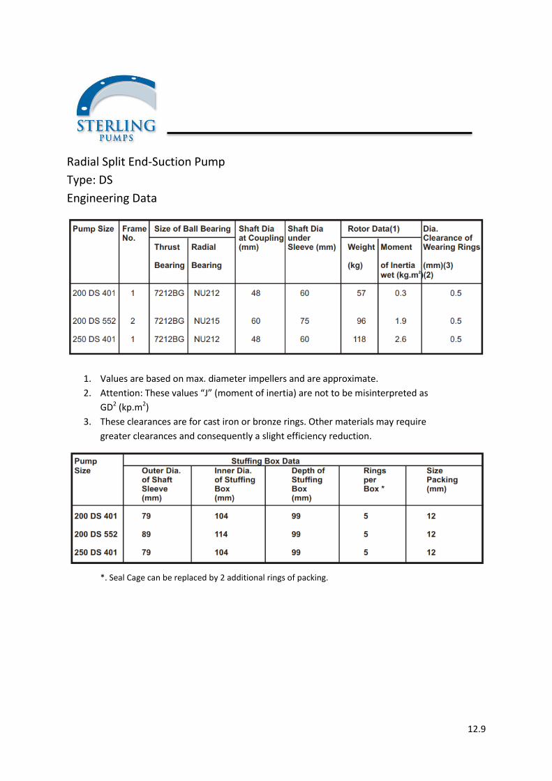
Radial Split End-Suction Pump
Type: DS
Engineering Data
1. Values are based on max. diameter impellers and are approximate.
2. Attention: These values “J” (moment of inertia) are not to be misinterpreted as
GD2 (kp.m2)
3. These clearances are for cast iron or bronze rings. Other materials may require
greater clearances and consequently a slight efficiency reduction.
*. Seal Cage can be replaced by 2 additional rings of packing.
12.10
Typical Specifications
Each pump shall be designed to pump sewage
containing solids and stringy materials with a
minimum of clogging. Each pump shall be rated at
m3/hr at total head of mtr. at rpm. In addition,
each pump shall be capable of producing not led
than m3/hr at a minimum total head of mtr at rated
speed. Minimum shut off head shall be mtr.
Variable speen pumps shall be capable of m3/hr at
a total head of mtr. at reduced speed of rpm.
Driver horsepower shall be min. so as to be non-
overloading from shutoff to minimum head
specified for full speed operation. Suction and
discharge connection shall be inches minimum and
the flanges shall be drilled in accordance with ANSI
standards for B16.5 flanges.
Casing – The pump casing shall be of the one piece
volute type with integral discharge flange and
arranged as shown on the drawings. It shall be
made of close grained cast iron and of sufficient
strength, weight and thickness to provide accurate
alignment and prevent excessive deflection.
The casing shall be designed to permit the removal
of the rotating assembly without disturbing the
suction or discharge connections and provided with
a large hand hole to permit inspection and cleaning
of the pump interior. The hand hole cover shall
match the contour of the casing. Three lifting eyes
shall be furnished to facilitate handling.
Each casing shall be hydrostatically tested to one
and one quarter times the maximum shit off
pressure and provided with three-quarter inch
vent, drain and gauge connections.
Suction Head – The suction head shall be of the
same material as the casing and designed to
provide equal flow distribution to the impeller eye.
It shall be provided with a flanged connection, a
hand hole with removable cover and a one-half
inch gauge tap connection.
Impeller – The impeller shall be single stage end
suction mixed flow enclosed type with a minimum
number of vanes and shall be designed to prevent
clogging and to pass solids, trash and stringy
materials contained in sewage.
The impellers shall be made of close grained cast
iron, accurately machined and polished to remove
hollows or projections which might encourage
cavitation. Each impeller shall be statically and
dynamically balanced prior to assembly.
The impeller shall be secured to the shaft with a
key and contoured lock nut which in turn is secured
by a locking screw. The arrangement shall be such
that the impeller cannot be loosened by torque
from either forward or reverse rotation.
Wearing rings – Removable wearing rings of unlike
hardness stainless steel shall be furnished on the
impeller and suction head and the axis of rotation.
They shall be securely fastened to prevent any
relative rotation, and designed to compensate for a
minimum of one-quarter inch wear. The impeller
ring shall be suitable chrome steel and the suction
head ring shall be chrome steel and exceed the
impeller ring hardness by not less than 50 points
Brinell hardness.
Pump Shaft and Sleeve – Pump shafts shall be of
heat treated alloy steel of sufficient size to transmit
the full driver horsepower with a liberal safety
factor and shall be accurately machined over the
entire length. The shafts shall be protected from
wear in the stuffing box by a hardened chrome
steel shaft sleeve sealed to prevent leakage
between the sleeve and the shaft.
Stuffing Box – The stuffing box shall be cast
integrally with the stuffing box head, designed for a
minimum for five rings of packing in addition to a
bronze/C.I. seal cage and suitable for clear water or
grease sealing. The stuffing box shall be readily
accessible and provided with a removable
bronze/C.I. gland to facilitate packing replacement
(or mechanical seal as specified). The stuffing box
head shall be tapped for a three-quarter inch drain
connection.

12.11
Centrifugal Pumps
Radially Split, Single Stage, Double Volute, End Suction Pump

12.12
Radially Split, Single Stage, Double Volute End Suction Pump
Product Description Pump Type DS
Pump
Type DS Pumps in standard construction are of horizontal, single stage, single suction,
double volute, foot mounted, overhung impeller design.
Spacer type couplings allow full inspection of the back pull out type pump, without
disturbing suction and discharge connections or driver position.
End suction and top discharge is the standard configuration. However, following alternative
arrangements are available:
Discharge nozzle in horizontal position, either left or right.
Centerline support for extreme conditions of service.
Vertical shaft arrangement (DSV).
Casing
The pump casing is radially split and the suction and discharge nozzles are cast integral with
the case. Double volute design for stable operation over a wide range.
Impeller
The impeller is a single suction, closed type, dynamically balanced, keyed to the shaft and
secured with a cap and positively locked bolt.
Wearing Rings
In standard construction these pumps are finished without wearing rings. If desired,
renewable wearing rings are available for the pump casing as an extra.

12.13
Radially Split, Single Stage, Double Volute End Suction Pump
Shaft
The large diameter shaft is supported by a cylindrical roller bearing at the pump end and a
pair of angular contact ball bearings at the drive end.
Lubrication
Grease lubrication is supplied as the standard. Conversion to oil lubrication can be effected.
In this case, the correct oil level would be maintained by a constant-level oiler.
Shaft Sleeve
The hook-type shaft sleeve, locked on the shaft between the impeller hub and shaft
shoulder, extends through the stuffing box and is positively driven by the impeller key.
Stuffing Box
The stuffing box with five rings of packing and a lantern ring, upon request, can be
converted to “mechanical seal”.

12.14
Radially Split, Single stage,
Double Volute End Suction Pump
PUMP MODEL 200 DS 401A
SPEED 1480 RPM
CURVES BASED ON COLD WATER CURVE SHEET NO.: TYPE DS
Eye Area total cm2 Suction Flange 300mm 12 inches
Discharge Flange 250mm 10 inches

12.15
Radially Split, Single stage,
Double Volute End Suction Pump
PUMP MODEL 200 DS 552A
SPEED 1480 RPM
CURVES BASED ON COLD WATER CURVE SHEET NO.: TYPE DS
Eye Area total cm2 Suction Flange 250mm 10 inches
Discharge Flange 250mm 8 inches

12.16
Radially Split, Single stage,
Double Volute End Suction Pump
PUMP MODEL 250 DS 401A
SPEED 1480 RPM
CURVES BASED ON COLD WATER CURVE SHEET NO.: TYPE DS
Eye Area total cm2 Suction Flange 300mm 12 inches
Discharge Flange 250mm 10 inches