Industrial DC/DC CONVERTER MGDI-100 Wide Input …gaia-converter.com/docs/ds/MGDI100W.pdf ·...
16
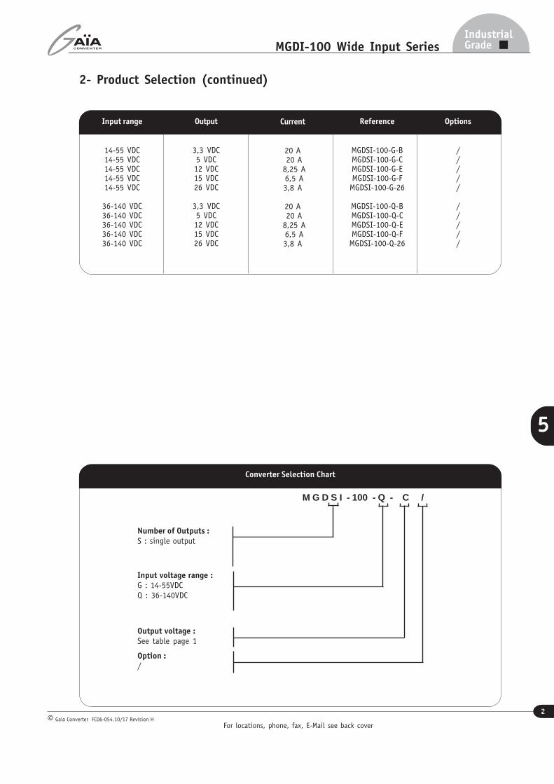
Industrial DC/DC CONVERTER MGDI-100 Wide Input : 100W POWER • Wide input range • Nominal power up to 100 W • High efficiency (typ. 88%) • Soft start • Galvanic isolation 1.500 VDC according to EN 60950 • Integrated LC input filter • Permanent short circuit protection • External synchronisation • External trim and sense adjustment : -20/+10% • No optocoupler for high reliability • RoHS process Gaia Converter FC06-054.10/17 Revision H © REDEFINING THE SOURCE OF POWER 1-General Industrial Grade For locations, phone, fax, E-Mail see back cover The MGDI-100 wide input series is a full family of DC/DC power modules designed for use in distributed power architecture where variable input voltage and transient are prevalent making them ideal particularly for transportation, railways or high-end industrial applications. These modu- les use a high frequency fixed swiching topology at 260KHz providing excellent reliability, low noise characteristics and high power density. Standard models are available with wide input voltage range of 14-55 and 36-140 volts for 24/36/72/110V bat- teries. The serie includes single output voltage choices of 2.5, 3.3, 5, 12, 15 and 26 volts (for 24Vdc applications). 4:1 & 5:1 Wide Input Single Output Metallic Case - 1 500 VDC Isolation The MGDI-100 serie is designed in conformity withsafety standards EN60950 and UL1950. All the modules are designed with LC network filters to minimize reflected input current ripple and output voltage ripple according to ease EN55022 and FCC Part 15J standard. The modules include a soft-start, an input undervoltage and overvoltage lock-out, a per- manent short circuit protection and a thermal protection to ensure efficient module protec- tions. The soft-start allows current limitation and eliminates inrush current during start-up. The short circuit protection completely protects the modules against short-circuits of any duration by a shut-down and restores to normal when the overload is removed. 5 2-Product Selection Input Voltage Range B : 3.3 VDC C : 5 VDC E : 12 VDC F : 15 VDC 26 : 26 VDC (for 24 VDC application) For lower output voltage below 3.3V please consult factory Output Permanent G : 14-55 VDC Q : 36-140 VDC Extended Range 55 VDC 175 VDC Single output model : MGDSI - 100 - input output
Transcript of Industrial DC/DC CONVERTER MGDI-100 Wide Input …gaia-converter.com/docs/ds/MGDI100W.pdf ·...
Industrial DC/DC CONVERTERMGDI-100 Wide Input : 100W POWER
• Wide input range
• Nominal power up to 100 W
• High efficiency (typ. 88%)
• Soft start
• Galvanic isolation 1.500 VDC according to EN 60950
• Integrated LC input filter
• Permanent short circuit protection
• External synchronisation
• External trim and sense adjustment : -20/+10%
• No optocoupler for high reliability
• RoHS process
Gaia Converter FC06-054.10/17 Revision H©
REDEFINING THE SOURCE OF POWER
1-General
IndustrialGrade
For locations, phone, fax, E-Mail see back cover
The MGDI-100 wide input series is a full family ofDC/DC power modules designed for use indistributed power architecture where variableinput voltage and transient are prevalent makingthem ideal particularly for transportation, railwaysor high-end industrial applications. These modu-les use a high frequency fixed swiching topologyat 260KHz providing excellent reliability, low noisecharacteristics and high power density. Standardmodels are available with wide input voltage rangeof 14-55 and 36-140 volts for 24/36/72/110V bat-teries. The serie includes single output voltagechoices of 2.5, 3.3, 5, 12, 15 and 26 volts (for24Vdc applications).
4:1 & 5:1 Wide InputSingle Output
Metallic Case - 1 500 VDC Isolation
The MGDI-100 serie is designed in conformitywithsafety standards EN60950 and UL1950.All the modules are designed with LC networkfilters to minimize reflected input current rippleand output voltage ripple according to easeEN55022 and FCC Part 15J standard.The modules include a soft-start, an inputundervoltage and overvoltage lock-out, a per-manent short circuit protection and a thermalprotection to ensure efficient module protec-tions. The soft-start allows current limitation andeliminates inrush current during start-up. Theshort circuit protection completely protects themodules against short-circuits of any durationby a shut-down and restores to normal whenthe overload is removed.
5
2-Product Selection
Input Voltage Range
B : 3.3 VDCC : 5 VDCE : 12 VDCF : 15 VDC26 : 26 VDC (for 24 VDC application)For lower output voltage below 3.3Vplease consult factory
Output
Permanent
G : 14-55 VDCQ : 36-140 VDC
Extended Range
55 VDC175 VDC
Single output model : MGDSI - 100 - input output
For locations, phone, fax, E-Mail see back cover
2
IndustrialGradeMGDI-100 Wide Input Series
Gaia Converter FC06-054.10/17 Revision H©
5
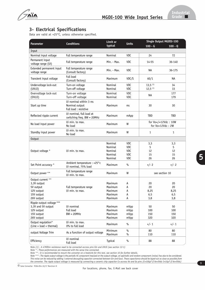
2- Product Selection (continued)
Current
20 A 20 A
8,25 A 6,5 A3,8 A
20 A 20 A
8,25 A 6,5 A3,8 A
Reference
MGDSI-100-G-BMGDSI-100-G-CMGDSI-100-G-EMGDSI-100-G-FMGDSI-100-G-26
MGDSI-100-Q-BMGDSI-100-Q-CMGDSI-100-Q-EMGDSI-100-Q-FMGDSI-100-Q-26
Output
3,3 VDC5 VDC12 VDC15 VDC26 VDC
3,3 VDC5 VDC12 VDC15 VDC26 VDC
Input range
14-55 VDC14-55 VDC14-55 VDC14-55 VDC14-55 VDC
36-140 VDC36-140 VDC36-140 VDC36-140 VDC36-140 VDC
Options
/////
/////
Converter Selection Chart
M G D S I - 100 - Q - C /
Number of Outputs :S : single output
Input voltage range :G : 14-55VDCQ : 36-140VDC
Output voltage :See table page 1
Option :/
For locations, phone, fax, E-Mail see back cover
3
IndustrialGradeMGDI-100 Wide Input Series
Gaia Converter FC06-054.10/17 Revision H©
5
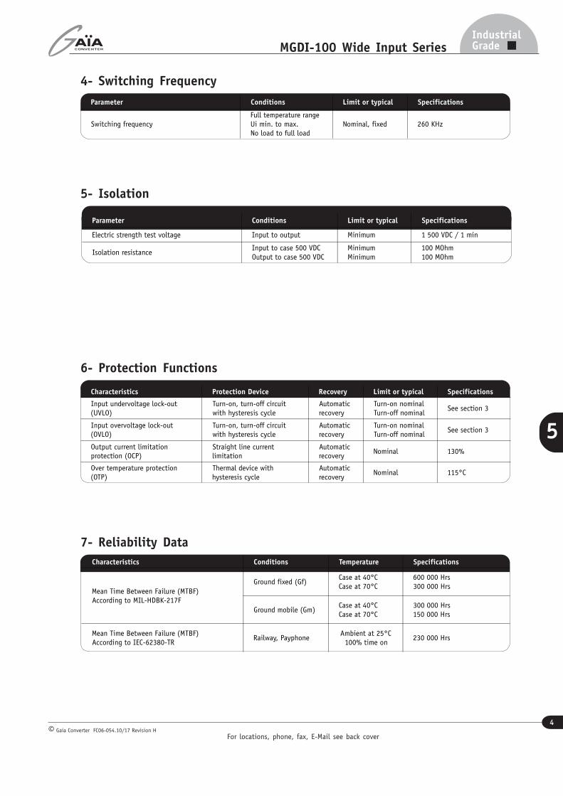
3- Electrical SpecificationsData are valid at +25°C, unless otherwise specified.
Parameter ConditionsLimit ortypical
UnitsSingle Output MGDSI-100
100 - G 100 - Q
Input
Nominal input voltage Full temperature range Nominal VDC 24 72
Permanent inputvoltage range (Ui)
Full temperature range Min. - Max. VDC 14-55 36-140
Extended permanent inputvoltage range
Full temperature range(Consult factory)
Min. - Max. VDC NA 36-175
Transient input voltageFull load(Consult factory)
Maximum VDC/S 60/1 NA
Undervoltage lock-out(UVLO)
Turn-on voltageTurn-off voltage
NominalNominal
VDCVDC
13,5 (1)
12,5 (1)
3433
Overvoltage lock-out(OVLO)
Turn-on voltageTurn-off voltage
NominalNominal
VDCVDC
NA177179
Start up timeUi nominal within 3 msNominal outputFull load : resistive
Maximum ms 30 30
Reflected ripple currentUi nominal, full load atswitching freq. BW = 20MHz
Maximum mApp TBD TBD
No load input powerUi min. to max.No load
Maximum Wfor Vo</=12Vdc : 10W
for Vo>12Vdc : 2W
Standby input powerUi min. to max.No load
Maximum W 1 1
Output
Output voltage * Ui min. to max.
NominalNominalNominalNominalNominal
VDCVDCVDCVDCVDC
3,35121526
3,35121526
Set Point accuracy *Ambient temperature : +25°cUi nominal, 75% load
Maximum % +/- 2 +/- 2
Output power **Full temperature rangeUi min. to max.
Maximum W see section 10
Output current **3,3V output5V output12V output15V output26V output
Full temperature rangeUi min. to max.
MaximumMaximumMaximumMaximumMaximum
AAAAA
2020
8,256,53,8
2020
8,256,53,8
Ripple output voltage ***3,3V and 5V output12V output15V output26V output
Ui nominalFull loadBW = 20MHz
MaximumMaximumMaximumMaximum
mVppmVppmVppmVpp
50100150320
50100150320
Output regulation*(Line + load + thermal)
Ui min. to max.0% to full load
Maximum % +/- 1 +/- 1
output Voltage Trim As a function of output voltageMinimumMaximum
%%
80110
80110
EfficiencyUi nominalFull load
Typical % 88 88
Note (1) : A 47KOhm resistance need to be connected accross pins Gin and UVLO (see section 12-1)
Note * : These performances are measured with the sense line connected.Note ** : It is recommended to mount the converter on a heatsink for this test, see section 10 for further details.
Note *** : The ripple output voltage is the periodic AC component imposed on the output voltage, an aperiodic and random component (noise) has also to be considered.
This noise can be reduced by adding 1 external decoupling capacitor connected between Gin and Gout. These capacitance should be layed-out as close as possible fromthe converter. The ripple output voltage is measured by connecting a ceramic chip capacitor Co accross Vo and Go pins (C=100µF if Vo<5Vdc C=10µF if Vo>5Vdc)
For locations, phone, fax, E-Mail see back cover
4
IndustrialGradeMGDI-100 Wide Input Series
Gaia Converter FC06-054.10/17 Revision H©
5
4- Switching Frequency
6- Protection Functions
Characteristics Protection Device Recovery Limit or typical Specifications
Input undervoltage lock-out(UVLO)
Turn-on, turn-off circuitwith hysteresis cycle
Automaticrecovery
Turn-on nominalTurn-off nominal
See section 3
Input overvoltage lock-out(OVLO)
Turn-on, turn-off circuitwith hysteresis cycle
Automaticrecovery
Turn-on nominalTurn-off nominal
See section 3
Output current limitationprotection (OCP)
Straight line currentlimitation
Automaticrecovery
Nominal 130%
Over temperature protection(OTP)
Thermal device withhysteresis cycle
Automaticrecovery
Nominal 115°C
7- Reliability Data
Parameter Conditions Limit or typical Specifications
Switching frequencyFull temperature rangeUi min. to max.No load to full load
Nominal, fixed 260 KHz
5- Isolation
Characteristics Conditions Temperature Specifications
Mean Time Between Failure (MTBF)According to MIL-HDBK-217F
Ground fixed (Gf)Case at 40°CCase at 70°C
600 000 Hrs300 000 Hrs
Ground mobile (Gm)Case at 40°CCase at 70°C
300 000 Hrs150 000 Hrs
Mean Time Between Failure (MTBF)According to IEC-62380-TR
Railway, PayphoneAmbient at 25°C100% time on
230 000 Hrs
Parameter Conditions Limit or typical Specifications
Electric strength test voltage Input to output Minimum 1 500 VDC / 1 min
Isolation resistanceInput to case 500 VDCOutput to case 500 VDC
MinimumMinimum
100 MOhm100 MOhm
For locations, phone, fax, E-Mail see back cover
5
IndustrialGradeMGDI-100 Wide Input Series
Gaia Converter FC06-054.10/17 Revision H©
5
Electromagnetic Interference according to EN55022
Conductednoise
emission
Configuration With 4 common mode capacitorsC
c = 10nF and external filter
Models
All models Class A
Radiatednoise
emission
Configuration With 4 common mode capacitors C c = 10 nFand external filterModels
All models Class B
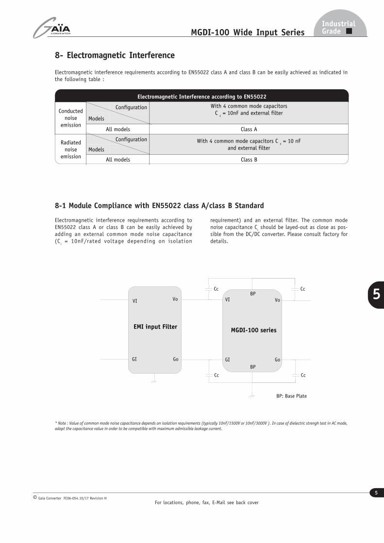
8- Electromagnetic Interference
Electromagnetic interference requirements according to EN55022 class A and class B can be easily achieved as indicated inthe following table :
Electromagnetic interference requirements according toEN55022 class A or class B can be easily achieved byadding an external common mode noise capacitance(C
C = 10nF/rated voltage depending on isolation
requirement) and an external filter. The common modenoise capacitance C
C should be layed-out as close as pos-
sible from the DC/DC converter. Please consult factory fordetails.
8-1 Module Compliance with EN55022 class A/class B Standard
* Note : Value of common mode noise capacitance depends on isolation requirements (typically 10nF/1500V or 10nF/3000V ). In case of dielectric strengh test in AC mode,
adapt the capacitance value in order to be compatible with maximum admissible leakage current.
Cc
Cc
Cc
Cc
BP
BP
MGDI-100 series
GI
VI Vo
Go
BP
BP
BP: Base Plate
EMI input Filter
Go
Vo
GI
VI
For locations, phone, fax, E-Mail see back cover
6
IndustrialGradeMGDI-100 Wide Input Series
Gaia Converter FC06-054.10/17 Revision H©
5
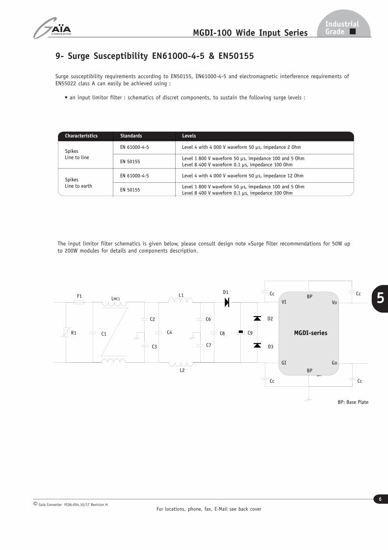
9- Surge Susceptibility EN61000-4-5 & EN50155
Surge susceptibility requirements according to EN50155, EN61000-4-5 and electromagnetic interference requirements ofEN55022 class A can easily be achieved using :
• an input limitor filter : schematics of discret components, to sustain the following surge levels :
L1LMC1
C9C1
C2
C3
C4 C8R1
C6
C7
L2
F1D1
D2
D3
C3
D2
D3
Cc
Cc
Cc
Cc
BP
BP
MGDI-series
GI
VI Vo
Go
BP
BP
BP: Base Plate
Characteristics Standards Levels
SpikesLine to line
EN 61000-4-5 Level 4 with 4 000 V waveform 50 µs, impedance 2 Ohm
EN 50155Level 1 800 V waveform 50 µs, impedance 100 and 5 OhmLevel 8 400 V waveform 0.1 µs, impedance 100 Ohm
SpikesLine to earth
EN 61000-4-5 Level 4 with 4 000 V waveform 50 µs, impedance 12 Ohm
EN 50155Level 1 800 V waveform 50 µs, impedance 100 and 5 OhmLevel 8 400 V waveform 0.1 µs, impedance 100 Ohm
The input limitor filter schematics is given below, please consult design note «Surge filter recommendations for 50W upto 200W modules for details and components description.
For locations, phone, fax, E-Mail see back cover
7
IndustrialGradeMGDI-100 Wide Input Series
Gaia Converter FC06-054.10/17 Revision H©
5
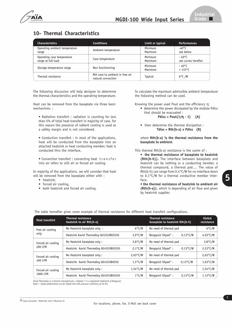
10- Thermal Characteristics
Characteristics Conditions Limit or typical Performances
Operating ambient temperaturerange
Ambient temperatureMinimumMaximum
-40°Csee below
Operating case temperaturerange at full load
Case temperatureMinimumMaximum
- 40°Csee curves herafter
Storage temperature range Non functionningMinimumMaximum
- 40°C+ 115°C
Thermal resistanceRth case to ambient in free airnatural convection
Typical 6°C /W
The following discussion will help designer to determinethe thermal characteristics and the operating temperature.
Heat can be removed from the baseplate via three basicmechanisms :
• Radiation transfert : radiation is counting for lessthan 5% of total heat transfert in majority of case, forthis reason the presence of radient cooling is used asa safety margin and is not considered.
• Conduction transfert : in most of the applications,heat will be conducted from the baseplate into anattached heatsink or heat conducting member; heat isconducted thru the interface.
• Convection transfert : convecting heat t r a n s f e rinto air refers to still air or forced air cooling.
In majority of the applications, we will consider that heatwill be removed from the baseplate either with :
• heatsink,• forced air cooling,• both heatsink and forced air cooling.
To calculate the maximum admissible ambient temperaturethe following method can be used.
Knowing the power used Pout and the efficiency η:• determine the power dissipated by the module Pdiss that should be evacuated :
Pdiss = Pout(1/ηηηηη - 1) (A)
• then determine the thermal dissipation :Tdiss = Rth(b-a) x Pdiss (B)
where Rth(b-a) is the thermal resistance from thebaseplate to ambient.
This thermal Rth(b-a) resistance is the summ of :• the thermal resistance of baseplate to heatsink(Rth(b-h)). The interface between baseplate andheatsink can be nothing or a conducting member, athermal compound, a thermal pad.... The value ofRth(b-h) can range from 0.4°C/W for no interface downto 0.1°C/W for a thermal conductive member inter-face.• the thermal resistance of heatsink to ambient air(Rth(h-a)), which is depending of air flow and givenby heatsink supplier.
The table hereafter gives some example of thermal resistance for different heat transfert configurations.
Heat transfertThermal resistanceheatsink to air Rth(h-a)
Thermal resistancebaseplate to heatsink Rth(b-h)
Globalresistance
Free air coolingonly
No Heatsink baseplate only : 6°C/W No need of thermal pad 6°C/W
Heatsink Aavid Thermalloy 824353B03250 3,9°C/W Bergquist Silpad* : 0,13°C/W 4,03°C/W
Forced air cooling200 LFM
No Heatsink baseplate only : 3,8°C/W No need of thermal pad 3,8°C/W
Heatsink Aavid Thermalloy 824353B03250 2,1°C/W Bergquist Silpad* : 0,13°C/W 2,23°C/W
Forced air cooling400 LFM
No Heatsink baseplate only : 2,63°C/W No need of thermal pad 2,63°C/W
Heatsink Aavid Thermalloy 824353B0250 1,5°C/W Bergquist Silpad* : 0,13°C/W 1,63°C/W
Forced air cooling1000 LFM
No Heatsink baseplate only : 1,54°C/W No need of thermal pad 1,54°C/W
Heatsink Aavid Thermalloy 824353B03250 1°C/W Bergquist Silpad* : 0,13°C/W 1,13°C/W
Aavid Thermalloy is a heasink manufacturers. «Silpad» © is a registered trademark of Bergquist.
Note* : Silpad performance are for Silpad 400 with pressure conditions of 50 Psi.
For locations, phone, fax, E-Mail see back cover
8
IndustrialGradeMGDI-100 Wide Input Series
Gaia Converter FC06-054.10/17 Revision H©
5
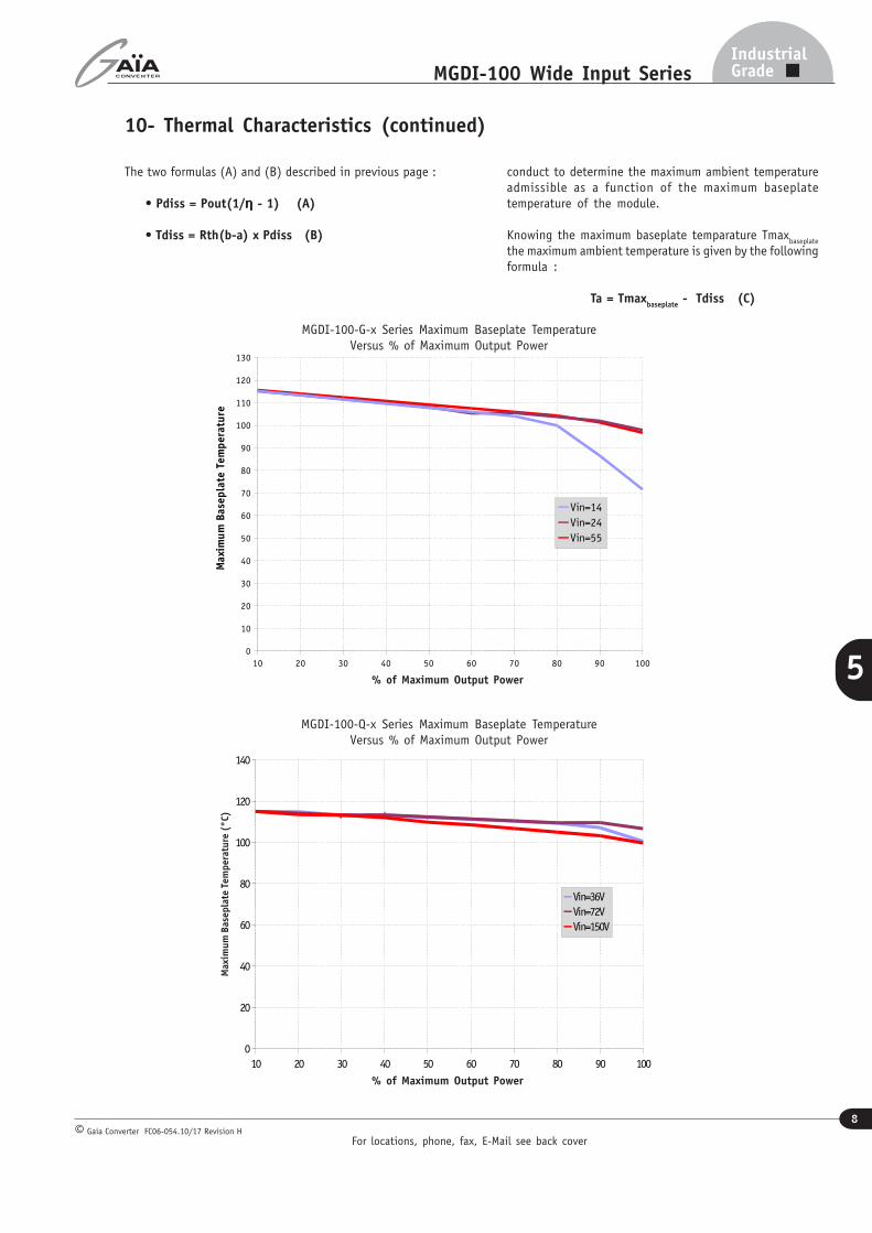
10- Thermal Characteristics (continued)
10 20 30 40 50 60 70 80 90 1000
20
40
60
80
100
120
140
Vin=36VVin=72VVin=150V
10 20 30 40 50 60 70 80 90 1000
10
20
30
40
50
60
70
80
90
100
110
120
130
Vin=14Vin=24Vin=55
Maxi
mum
Bas
epla
te T
emper
ature
Max
imum
Bas
epla
te T
emper
ature
(°C)
MGDI-100-Q-x Series Maximum Baseplate TemperatureVersus % of Maximum Output Power
MGDI-100-G-x Series Maximum Baseplate TemperatureVersus % of Maximum Output Power
The two formulas (A) and (B) described in previous page :
• Pdiss = Pout(1/ηηηηη - 1) (A)
• Tdiss = Rth(b-a) x Pdiss (B)
conduct to determine the maximum ambient temperatureadmissible as a function of the maximum baseplatetemperature of the module.
Knowing the maximum baseplate temparature Tmaxbaseplate
the maximum ambient temperature is given by the followingformula :
Ta = Tmaxbaseplate
- Tdiss (C)
% of Maximum Output Power
% of Maximum Output Power
For locations, phone, fax, E-Mail see back cover
9
IndustrialGradeMGDI-100 Wide Input Series
Gaia Converter FC06-054.10/17 Revision H©
5
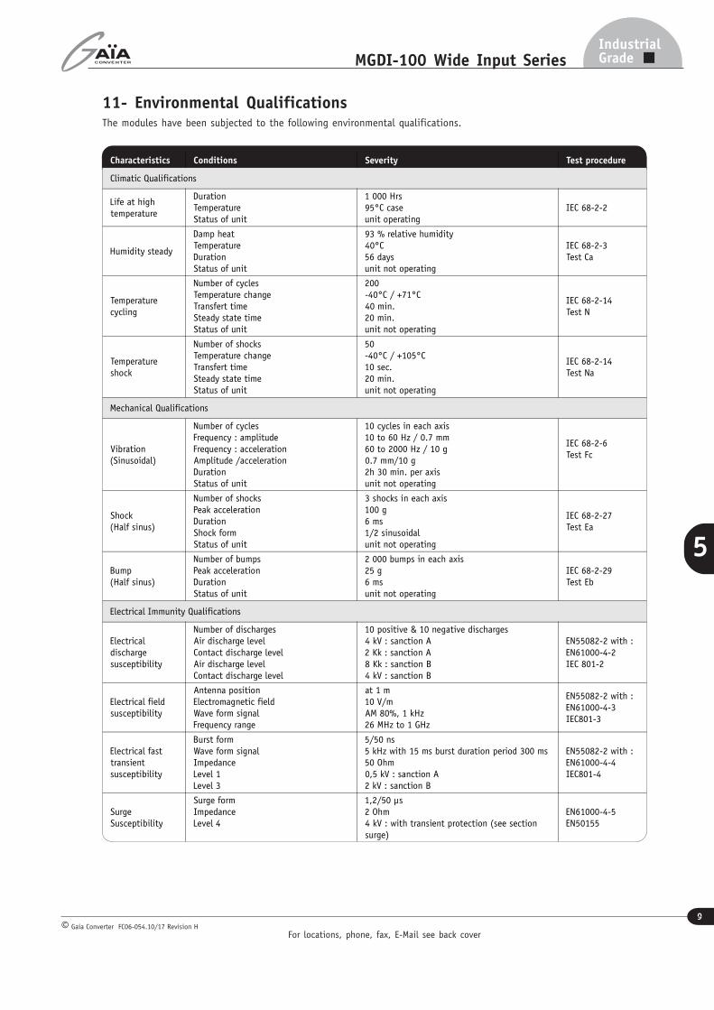
11- Environmental QualificationsThe modules have been subjected to the following environmental qualifications.
Characteristics Conditions Severity Test procedure
Climatic Qualifications
Life at hightemperature
DurationTemperatureStatus of unit
1 000 Hrs95°C caseunit operating
IEC 68-2-2
Humidity steady
Damp heatTemperatureDurationStatus of unit
93 % relative humidity40°C56 daysunit not operating
IEC 68-2-3Test Ca
Temperaturecycling
Number of cyclesTemperature changeTransfert timeSteady state timeStatus of unit
200-40°C / +71°C40 min.20 min.unit not operating
IEC 68-2-14Test N
Temperatureshock
Number of shocksTemperature changeTransfert timeSteady state timeStatus of unit
50-40°C / +105°C10 sec.20 min.unit not operating
IEC 68-2-14Test Na
Mechanical Qualifications
Vibration(Sinusoidal)
Number of cyclesFrequency : amplitudeFrequency : accelerationAmplitude /accelerationDurationStatus of unit
10 cycles in each axis10 to 60 Hz / 0.7 mm60 to 2000 Hz / 10 g0.7 mm/10 g2h 30 min. per axisunit not operating
IEC 68-2-6Test Fc
Shock(Half sinus)
Number of shocksPeak accelerationDurationShock formStatus of unit
3 shocks in each axis100 g6 ms1/2 sinusoidalunit not operating
IEC 68-2-27Test Ea
Bump(Half sinus)
Number of bumpsPeak accelerationDurationStatus of unit
2 000 bumps in each axis25 g6 msunit not operating
IEC 68-2-29Test Eb
Electrical Immunity Qualifications
Electricaldischargesusceptibility
Number of dischargesAir discharge levelContact discharge levelAir discharge levelContact discharge level
10 positive & 10 negative discharges4 kV : sanction A2 Kk : sanction A8 Kk : sanction B4 kV : sanction B
EN55082-2 with :EN61000-4-2IEC 801-2
Electrical fieldsusceptibility
Antenna positionElectromagnetic fieldWave form signalFrequency range
at 1 m10 V/mAM 80%, 1 kHz26 MHz to 1 GHz
EN55082-2 with :EN61000-4-3IEC801-3
Electrical fasttransientsusceptibility
Burst formWave form signalImpedanceLevel 1Level 3
5/50 ns5 kHz with 15 ms burst duration period 300 ms50 Ohm0,5 kV : sanction A2 kV : sanction B
EN55082-2 with :EN61000-4-4IEC801-4
SurgeSusceptibility
Surge formImpedanceLevel 4
1,2/50 µs2 Ohm4 kV : with transient protection (see sectionsurge)
EN61000-4-5EN50155
For locations, phone, fax, E-Mail see back cover
10
IndustrialGradeMGDI-100 Wide Input Series
Gaia Converter FC06-054.10/17 Revision H©
5
Baseplate Temperature
On
115˚c
Off10˚c
Vin
On
OVLO
Turn-off
Off
UVLO
Turn-on
UVLO
Turn-offOVLO
Turn-on
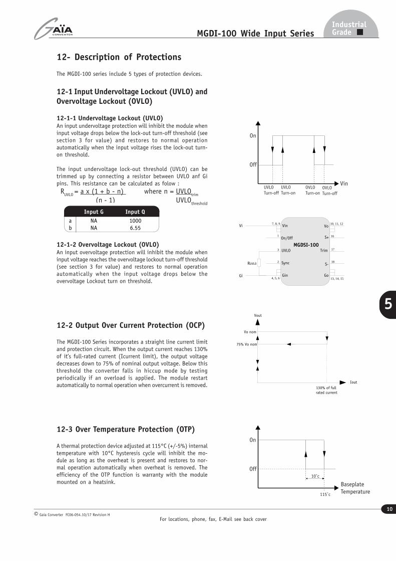
12- Description of Protections
The MGDI-100 series include 5 types of protection devices.
12-1 Input Undervoltage Lockout (UVLO) andOvervoltage Lockout (OVLO)
12-1-1 Undervoltage Lockout (UVLO)An input undervoltage protection will inhibit the module wheninput voltage drops below the lock-out turn-off threshold (seesection 3 for value) and restores to normal operationautomatically when the input voltage rises the lock-out turn-on threshold.
The input undervoltage lock-out threshold (UVLO) can betrimmed up by connecting a resistor between UVLO anf Gipins. This resistance can be calculated as folow : R
UVLO = a x (1 + b - n) where n = UVLO
trim
(n - 1) UVLOthreshold
12-1-2 Overvoltage Lockout (OVLO)An input overvoltage protection will inhibit the module wheninput voltage reaches the overvoltage lockout turn-off threshold(see section 3 for value) and restores to normal operationautomatically when the input voltage drops below theovervoltage Lockout turn on threshold.
12-2 Output Over Current Protection (OCP)
The MGDI-100 Series incorporates a straight line current limitand protection circuit. When the output current reaches 130%of it’s full-rated current (Icurrent limit), the output voltagedecreases down to 75% of nominal output voltage. Below thisthreshold the converter falls in hiccup mode by testingperiodically if an overload is applied. The module restartautomatically to normal operation when overcurrent is removed.
12-3 Over Temperature Protection (OTP)
A thermal protection device adjusted at 115°C (+/-5%) internaltemperature with 10°C hysteresis cycle will inhibit the mo-dule as long as the overheat is present and restores to nor-mal operation automatically when overheat is removed. Theefficiency of the OTP function is warranty with the modulemounted on a heatsink.
RUVLO
Gi
Vi
MGDSI-100
S-
Gin
Vin Vo
On/Off
Go
Trim
S+
Sync
UVLO
7, 8, 9
3
2
1
10, 11, 12
16
17
18
4, 5, 6 13, 14, 15
130% of fullrated current
75% Vo nom
Vo nom
Vout
Iout
Input G Input Q
a
b
NA
NA
1000
6.55
For locations, phone, fax, E-Mail see back cover
11
IndustrialGradeMGDI-100 Wide Input Series
Gaia Converter FC06-054.10/17 Revision H©
5
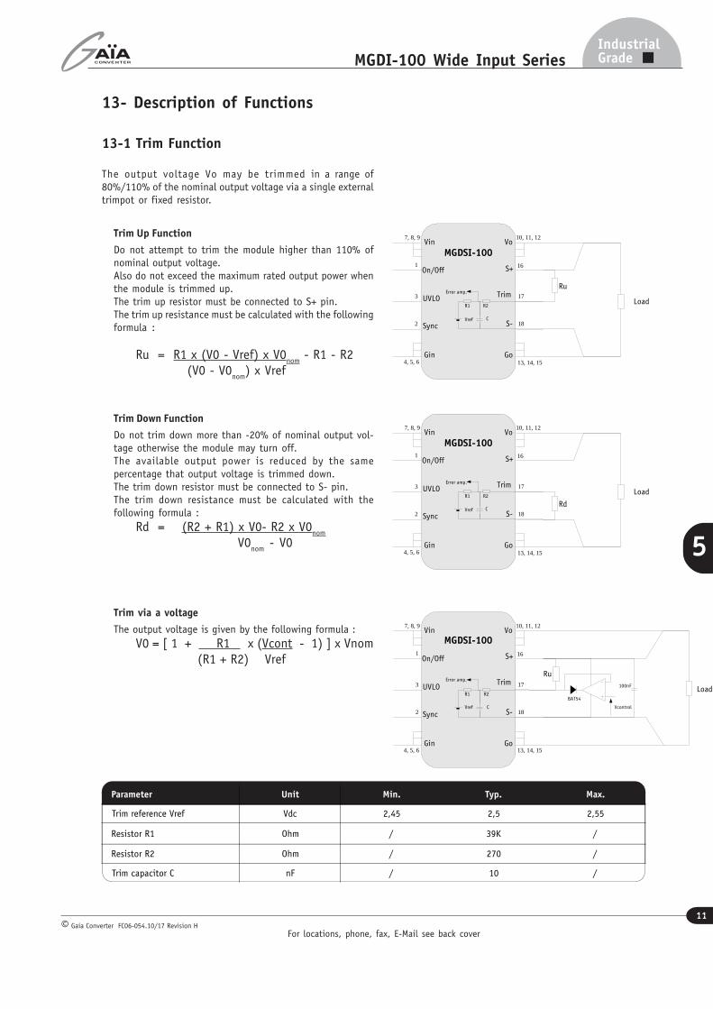
13- Description of Functions
13-1 Trim Function
The output voltage Vo may be trimmed in a range of80%/110% of the nominal output voltage via a single externaltrimpot or fixed resistor.
Trim Up Function
Do not attempt to trim the module higher than 110% ofnominal output voltage.Also do not exceed the maximum rated output power whenthe module is trimmed up.The trim up resistor must be connected to S+ pin.The trim up resistance must be calculated with the followingformula :
Ru = R1 x (V0 - Vref) x V0nom
- R1 - R2 (V0 - V0
nom) x Vref
Trim Down Function
Do not trim down more than -20% of nominal output vol-tage otherwise the module may turn off.The available output power is reduced by the samepercentage that output voltage is trimmed down.The trim down resistor must be connected to S- pin.The trim down resistance must be calculated with thefollowing formula :
Rd = (R2 + R1) x V0- R2 x V0nom
V0nom
- V0
Trim via a voltage
The output voltage is given by the following formula :V0 = [ 1 + R1 x (Vcont - 1) ] x Vnom
(R1 + R2) Vref
Parameter Unit Min. Typ. Max.
Trim reference Vref Vdc 2,45 2,5 2,55
Resistor R1 Ohm / 39K /
Resistor R2 Ohm / 270 /
Trim capacitor C nF / 10 /
MGDSI-100
S-
Gin
Vin Vo
On/Off
Go
Trim
S+
Sync
UVLO
7, 8, 9
3
2
1
10, 11, 12
16
17
18
4, 5, 6 13, 14, 15
Load
RdR1 R2
CVref
Error amp.
MGDSI-100
S-
Gin
Vin Vo
On/Off
Go
Trim
S+
Sync
UVLO
7, 8, 9
3
2
1
10, 11, 12
16
17
18
4, 5, 6 13, 14, 15
R1 R2
CVref
Error amp.
Load
Ru
Vcontrol
100nF
BAT54
MGDSI-100
S-
Gin
Vin Vo
On/Off
Go
Trim
S+
Sync
UVLO
7, 8, 9
3
2
1
10, 11, 12
16
17
18
4, 5, 6 13, 14, 15
Load
Ru
R1 R2
CVref
Error amp.
For locations, phone, fax, E-Mail see back cover
12
IndustrialGradeMGDI-100 Wide Input Series
Gaia Converter FC06-054.10/17 Revision H©
5
Load
MGDSI-100
S-
Gin
Vin Vo
On/Off
Go
Trim
S+
Sync
UVLO
7, 8, 9
3
2
1
10, 11, 12
16
17
18
4, 5, 6 13, 14, 15
13- Description of Functions (continued)
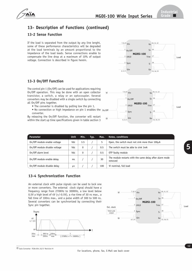
13-3 On/Off Function
The control pin 1 (On/Off) can be used for applications requiringOn/Off operation. This may be done with an open collectortransistor, a switch, a relay or an optocoupler. Severalconverters may be disabled with a single switch by connectingall On/Off pins together.
• The converter is disabled by pulling low the pin 1.• No connection or high impedance on pin 1 enables theconverter.
By releasing the On/Off function, the converter will restartwithin the start up time specifications given in table section 3
13-4 Synchronization Function
An external clock with pulse signals can be used to lock oneor more converters. The external clock signal should have afrequency range from 270KHz to 300KHz, a low level below0,5V a high level of 4V (+/-0.5V), a rise time of 30 ns max., afall time of 100ns max., and a pulse width of 300 to 500 ns.Several converters can be synchronized by connecting theirSync pin together.
Parameter Unit Min. Typ. Max. Notes, conditions
On/Off module enable voltage Vdc 3.5 / 5 Open, the switch must not sink more than 100µA
On/Off module disable voltage Vdc 0 / 0.5 The switch must be able to sink 1mA
On/Off alarm level Vdc 0 / 0.5 OTP faulty module
On/Off module enable delay ms / / 30The module restarts with the same delay after alarm mode
removed
On/Off module disable delay µs / / 100 Vi nominal, full load
t
4V
+/- 0,5
300 to
500ns
Vsync
0V
100ns
max
30ns
maxT
( 270Khz < F < 300Khz )
13-2 Sense Function
If the load is separated from the output by any line lenght,some of these performance characteristics will be degradedat the load terminals by an amount proportional to theimpedance of the load leads. Sense connections enable tocompensate the line drop at a maximum of 10% of outputvoltage. Connection is described in figure herein.
Load
On/Off
Gi
Vi
MGDSI-100
S-
Gin
Vin Vo
On/Off
Go
Trim
S+
Sync
UVLO
7, 8, 9
3
2
1
10, 11, 12
16
17
18
4, 5, 6 13, 14, 15
Load
Totem poleoutput
Gi
Vi
Ext. clock
MGDSI-100
S-
Gin
Vin Vo
On/Off
Go
Trim
S+
Sync
UVLO
7, 8, 9
3
2
1
10, 11, 12
16
17
18
4, 5, 6 13, 14, 15
For locations, phone, fax, E-Mail see back cover
13
IndustrialGradeMGDI-100 Wide Input Series
Gaia Converter FC06-054.10/17 Revision H©
5
14- Application Notes
Load
Gi
Vi
MGDSI-100
S-
Gin
Vin Vo
On/Off
Go
Trim
S+
Sync
UVLO
7, 8, 9
3
2
1
10, 11, 12
16
17
18
4, 5, 6 13, 14, 15
Load
MGDSI-100
S-
Gin
Vin Vo
On/Off
Go
Trim
S+
Sync
UVLO
7, 8, 9
3
2
1
10, 11, 12
16
17
18
4, 5, 6 13, 14, 15
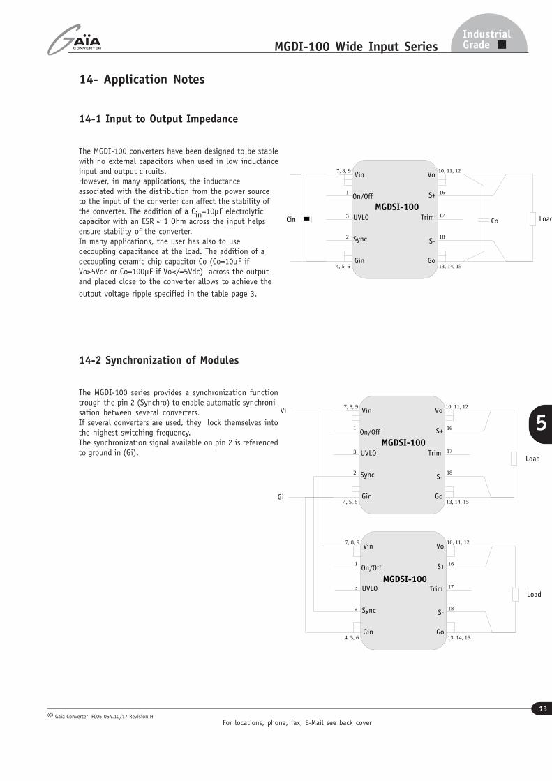
14-1 Input to Output Impedance
The MGDI-100 converters have been designed to be stablewith no external capacitors when used in low inductanceinput and output circuits.However, in many applications, the inductanceassociated with the distribution from the power sourceto the input of the converter can affect the stability ofthe converter. The addition of a Cin=10µF electrolyticcapacitor with an ESR < 1 Ohm across the input helpsensure stability of the converter.In many applications, the user has also to usedecoupling capacitance at the load. The addition of adecoupling ceramic chip capacitor Co (Co=10µF ifVo>5Vdc or Co=100µF if Vo</=5Vdc) across the outputand placed close to the converter allows to achieve the
output voltage ripple specified in the table page 3.
14-2 Synchronization of Modules
The MGDI-100 series provides a synchronization functiontrough the pin 2 (Synchro) to enable automatic synchroni-sation between several converters.If several converters are used, they lock themselves intothe highest switching frequency.The synchronization signal available on pin 2 is referencedto ground in (Gi).
Load
MGDSI-100
S-
Gin
Vin Vo
On/Off
Go
Trim
S+
Sync
UVLO
7, 8, 9
3
2
1
10, 11, 12
16
17
18
4, 5, 6 13, 14, 15
CoCin
For locations, phone, fax, E-Mail see back cover
14
IndustrialGradeMGDI-100 Wide Input Series
Gaia Converter FC06-054.10/17 Revision H©
5
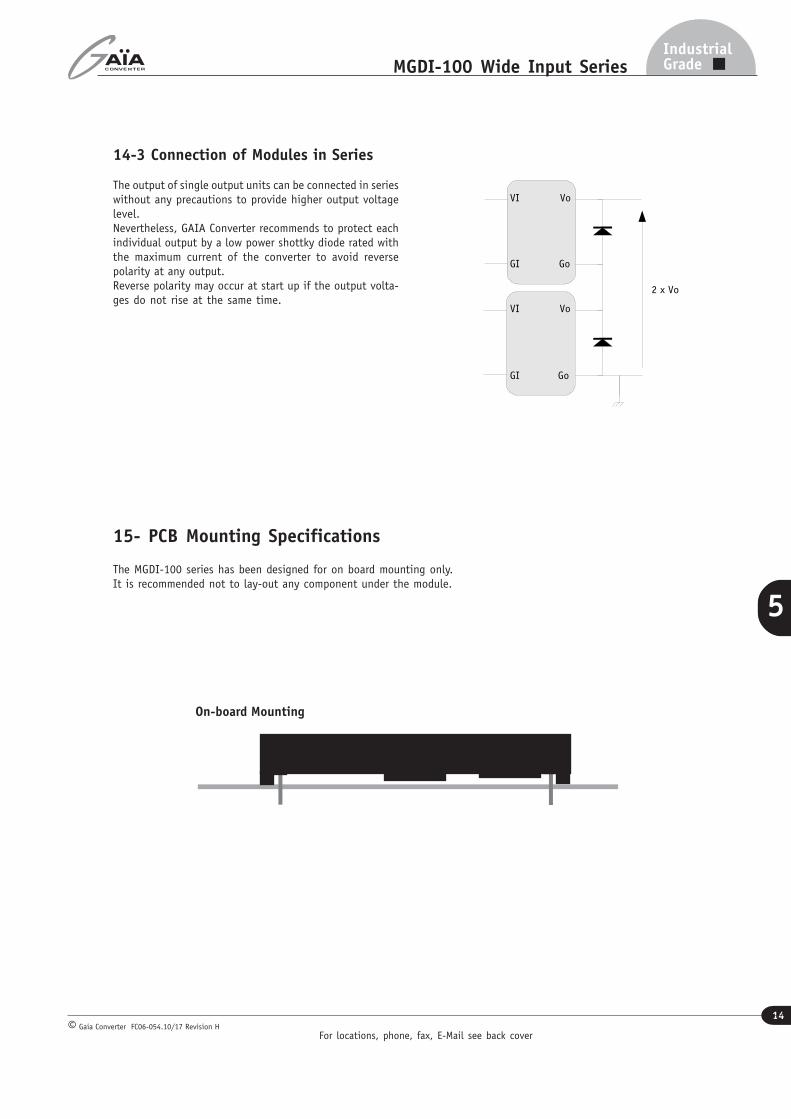
15- PCB Mounting Specifications
The MGDI-100 series has been designed for on board mounting only.It is recommended not to lay-out any component under the module.
On-board Mounting
Go
Vo
GI
VI
Go
Vo
GI
VI
2 x Vo
14-3 Connection of Modules in Series
The output of single output units can be connected in serieswithout any precautions to provide higher output voltagelevel.Nevertheless, GAIA Converter recommends to protect eachindividual output by a low power shottky diode rated withthe maximum current of the converter to avoid reversepolarity at any output.Reverse polarity may occur at start up if the output volta-ges do not rise at the same time.
For locations, phone, fax, E-Mail see back cover
15
IndustrialGradeMGDI-100 Wide Input Series
Gaia Converter FC06-054.10/17 Revision H©
5
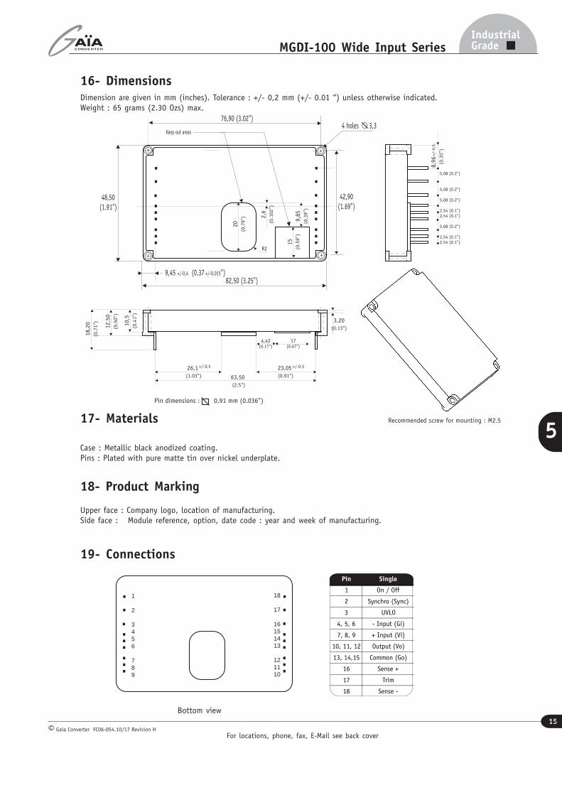
16- DimensionsDimension are given in mm (inches). Tolerance : +/- 0,2 mm (+/- 0.01 “) unless otherwise indicated.Weight : 65 grams (2.30 Ozs) max.
Pin dimensions : 0,91 mm (0.036")
10,5
(0.4
1")
12,5
0
(0.5
0")
82,50 (3.25")
76,90 (3.02")4 holes 3,3
42,90 (1.69")
48,50 (1.91")
3,20
(0.13")
18,2
0
(0.7
1")
20
(0.7
9") 2
,6
(0.1
02")
4,42 (0.17")
8,9
6
(
0.3
5")
+/-0
,5
5,08 (0.2")
5,08 (0.2")
5,08 (0.2")
2,54 (0.1") 2,54 (0.1")
5,08 (0.2")
2,54 (0.1") 2,54 (0.1")
63,50
(2.5")
23,05
(0.91")
+/-0,5 26,1
(1.03")
+/-0,5
9,45 +/-0,4 (0.37 +/-0.015")
R2
9,8
5
(0.3
9")
17 (0.67")
15
(0.5
9")
Keep out areas
19- Connections
1 2 3 4 5 6 7 8 9
18 17 16 15 14 13 12 11 10
Pin Single
1 On / Off
2 Synchro (Sync)
3 UVLO
4, 5, 6 - Input (Gi)
7, 8, 9 + Input (Vi)
10, 11, 12 Output (Vo)
13, 14,15 Common (Go)
16 Sense +
17 Trim
18 Sense -
Bottom view
17- Materials
Case : Metallic black anodized coating.Pins : Plated with pure matte tin over nickel underplate.
18- Product Marking
Upper face : Company logo, location of manufacturing.Side face : Module reference, option, date code : year and week of manufacturing.
Recommended screw for mounting : M2.5
Information given in this datasheet is believed to be accurate and reliable. However, no responsibility is assumed for the consequence of its use nor for any infringement of patents or other rights of third parties which may result from its use.These products are sold only according to GAIA Converter general conditions of sale, unless otherwise confirmed by writing. Specifications subject to change without notice.
Prin
ted
in F
ranc
e by
GAIA
Con
vert
er G
aia
Conv
erte
r F
C06-
054.
10/1
7 Re
visi
on H
. Gr
aphi
sme
: Ph
ilipp
e Cl
icq
Represented by :
For more detailed specifications and applications information, contact :
International HeadquartersGAÏA Converter - France
ZI de la Morandière33185 LE HAILLAN - FRANCETel. : + (33)-5-57-92-12-80Fax : + (33)-5-57-92-12-89
North American HeadquartersGAÏA Converter Canada, Inc4038 Le Corbusier BlvdLAVAL, QUEBEC - CANADA H7L 5R2Tel. : (514)-333-3169Fax : (514)-333-4519